course on basic hydraulics for the vanuatu rural water supply
TRANSCRIPT

COURSE ONBasic Hydraulics for the Vanuatu Rural Water Supply
3-28 April 200016 April-1 0 May 2001
Paula DaweSOPAC Water Resources Unit
May 2001 SOPAC Miscellaneous Report 419
This work has been supported by NZODA the Canadian organization CUSO

[3]
TABLE OF CONTENTS
INTRODUCTION 4
ACKNOWLEDGEMENTS 4
PARTiCiPANTS 4
HYDRAULIC TRAINING COURSE ACTIVITIES AND COURSE MATERIAL .4
RECOMMENDATIONS FOR THE ADVANCED TRAINING COURSE 5
APPENDICI ESA Hydraulic Couse NotesB Worked Hydraulic SolutionsC Material Not Covered/Material for Advanced Hydraulics CourseD Course Review by Participants
[SOPAC Miscellaneous Report 419 - Dawe]

[4]
INTRODUCTION
During a field visit to Vanuatu in September 1999 by WRU member of staff Harald Sch6elzelfor work on the NZODA funded Water Demand Management Project, groundwork for thistraining course was laid. The WRU trip coincided with a training assessment mission for theVanuatu Department of Geology, Mines and Water Resources (DGMWR) conducted byNZODA. The NZODA consultant saw good opportunities for SOPAC to provide training onbasic hydraulics for selected members of Rural Water Supply staff. Funding for the trainingwas to be provided by NZODA.
Once participants were selected a flexible training program was developed consisting of 2courses, a beginner and an advanced course that would be given to two members of theRural Water Supply.
The beginner's training course took place during two different sessions from 3-28 April 2000and 16 April-1 0 May 2001. The venue for the course was the SOPAC Headquarters, MeadRoad, Suva.
The advanced training course is yet to be conducted for either participant.
ACKNOWLEDGEMENTS
SOPAC would like to thank both trainees for their full cooperation and participation during thecourse and to NZODA for their financial support.
PARTICIPANTS
The following members of the Vanuatu Rural Water Supply (DGMWR) participated in thetraining course.
Vanuatu Rural Water SuVanuatu Rural Water SU
HYDRAULIC TRAINING COURSE ACTIVITIES AND COURSE MATERIAL
Major topics covered during the course are as follows:
• Review of Mathematical Relationships• Properties of Fluids• Hydrostatics• Hydrodynamics• Real Fluid Flow• Head Loss• Components of a Water Distribution System• Design of Distribution Systems
Complete course notes and practical examples and their solutions can be found in AppendixA and B.
[SOPAC Miscellaneous Report 419 - Dawe]

[5]
RECOMMENDATIONS FOR THE ADVANCED TRAINING COURSE
Response from the training course was very positive and it was felt that the trainees left witha good grasp of fundamentals. Course material not covered during the period of training isincluded in Appendix C. These and other topic that should be included in the advancedtraining course are as follows:
• Design of pumps• Economic costing of designs• Considerations when designing the layout of a distribution network• Creating ground profiles• Design of rural and urban systems• Basic hydrology and watershed analysis
[SOPAC Miscellaneous Report 419 - Dawe]

[6]
Appendix A:Hydraulic Course Notes
[SOPAC Miscellaneous Report 419 - Dawe]

[7]
INTRODUCTION
Review of Mathematical RelationshipsDirectly Proportional- as one value increases, the other does at the same rate (y=x)Square Relationship - as one value increases, the other does at a rate squared (y=x?)Cubed Relationship - as one value increase, the other does at a rate cubed (y=K)Inversely Proportional- as one value increases, the other decreases (y=1/x)Square Root Relationship - as one value increases, the other decreases at a rateproportional to the square root of that value (y=x~Constant MUltiplier Relationship- as one value increases, the other does at a rate times theconstant value applied to it (y=2x)
l . ( I) distannce(meters)ve octty meters sec = -------time(sec)
Since velocity and distance are directly proportional, as distance increases so does the valueof velocity.
iv= i dt
However, since time and velocity are inversely related, as one value increases the other willdecrease. If time increase, velocity will correspondingly decrease.
J-v=_dit
If you think of a trip that you make in your car, these kinds of relationships become more real.If you travel to the store one-day in 15 minutes, and the next day it takes you 30 minutes,your velocity (or speed) on the first day was obviously greater.
Exercises:
Solve the following equation for Area: Q=vAA is inversely / directly proportional to Q?A is inversely / directly proportional to v?If the units of v are mls and the units of A are m2
, what are the units of Q?If the value of v increases, will the value of A increase / decrease?If the value of A increases, will the value of Q increase / decrease?
[SOPAC Miscellaneous Report 419 - Dawe]

[8]
What does the following equal?
(~f?SlopeFor linear relationships such as y=x and y=2x the slope can be described as the rise of thatline over the run of that line. The following equation and figure illustrate this:
LJIR;* I
l rise Y2 - Yl I Run Is ope = -- = ~-----:.-'-run X2 -Xl
What is the slope of the following lines?y=0.5xy=8x+20
TrigonometryFor a right-angled triangle, the following trigonometric relationships can be used to determinethe degree of an angle or the length of a side of a triangle.
sin e = opp cos e = ad) tan e = opp hyp = ~ ad/ + oppihyp hyp ad}
Lj10" I
I adj IWhere:Hyp = the hypotenuse, or side of the triangle opposite the right anglee = one of the two angles in the triangle that is not the 90° right angleopp = the side of the triangle opposite to the angle eadj = the side of a triangle adjacent to the angle e
The above relationships can be remembered using the following key:some old hags, can't afford husbands, till old age
ConstantsThe following are some frequently used scientific constants:
Density of water 1000 ku/rn"Acceleration due to gravity 9.81 m/s"Kinematic Viscosity @ 20°C 1.007x10·0
Atmospheric Pressure 1.01x10° Pa
[SOPAC Miscellaneous Report 419 - Dawe]

[9]
UnitsThere are a number of different quantities often used in hydraulics. Each of these quantitieshas a different units associated with it. Depending on where you are in the world, differentunits might be used to describe the same quantities. Conversions from one unit to anotherare often required. The following table describes often used quantities used in hydraulics,their units, and factors that can be used to convert one unit to another.
Quantity SI Unit Symbol ConversionArea Square meter m£ rnf = 2.59 krn"
Acre = 4047 m2
Density Kilograms per cubic kg/m<lmeter
Energy Joule JFlow Cubic meter per second m<l/s fe/s = 0.0238 m£/sForce Newton N Ib = 4.448 NLenqth Meter m ft = 0.3048 mMass Kilogram kg Ib = 0.4536 kg
ton = 907.2 kgPressure Pascal Pa psi = 6.895 kPa
kPa = 10.197 cm of WaterPower Watt W hp = 745.7 WTime Seconds sVelocity Meters per second m/s ftls = 0.3048 rn/sVolume Cubic meter rn" ft<l= 0.02832 rrr'
Qal = 0.003785 m3
Exercises:Convert 300 kPa to an equivalent pressure in meters of water.Given a velocity of 12.5 ftls and a pipe cross sectional area of 0.5 m2, what is the flowthrough the pipe?What are the component units of Energy given that the equation for energy is E= mgh?What are the component units of Pressure given that the equation for pressure is:
}force .Pr essure = (Force = mass x acceleration)
Area
Sign ConventionWhen a value describing a quantity has direction it is called a vector.Of the above listed quantities which are vectors?
Sign convention becomes important when dealing with vectors. For instance velocity andflow can both be negative, if they are in the opposite direction to the recording convention.The following diagrams illustrate this.
[;J ~G:J
Q A-B = 50 m3/s Q B-A = -50 m3/s
[SOPAC Miscellaneous Report 419 - Dawe]

[10]
PHYSICAL PROPERTIES OF FLUIDS
Definition of a Fluid• a material such as water or air that cannot preserve its shape for any length of time,
unless it is constrained by surrounding surfaces.
The inability of fluids to resist shearing stress gives them their characteristic ability to flow. Afluid is then a material that will deform continuously under the action of shear stresses.Shear stress is caused by forces acting tangentially to the surface of the fluid. Thedeformation occurs as the fluid starts to flow. For example, wind blowing over the surface ofthe ocean creates a shear stress on the water's surface that deforms the otherwise stillsurface to create moving waves.
Can you name several other fluids?
Viscosity• determines the speed of spreading in the fluid as it loses its original shape under a
deforming force• a measure of the internal friction of a fluid, or its resistance to flow and movement
Because of viscosity, shear forces are caused in a fluid, which sets up a velocity gradientacross the flowing fluid area. For example, velocity gradients are always caused when a fluidflows over a solid surface, for the fluid layer immediately next to the surface adheres to it,with the layers above slipping over the ones below. Thus a shear stress always exists whensuch a flow occurs, and this stress always opposes the fluid motion. If the whole mass of thefluid is at rest relative to the boundaries, then there can be no velocity gradients, and therewill be no shear forces. It is an observed fact that the velocity at a solid boundary is zero andthat velocity increases with distance from the ",,,,,,",,",,
The shear stress, 't (N/m2), can be calculated from the following equation:
r=j.lVld
Where, u, is the dynamic viscosity, v is the velocity, and d is the distance between the fixedand moving surfaces. In hydraulics there are two types of viscosity, dynamic and kinematic.Kinematic viscosity, v, can be calculated as follows:v = /11 p
Density• the mass of fluid contained in a unit volume.
The term density, p, is one way to measure the number of molecules per unit volume in amaterial. Since molecular activity and spacing increase with temperature, fewer molecules
[SOPAC Miscellaneous Report 419 - Dawe]

[11]
exist in a given volume of fluid as temperature rises. Thus, density decreases with increasingtemperature.
What mathematical relationship describes temperature's effect on density?
Compressibility• all fluids may be compressed by the application of pressure.
However, for purposes in hydraulic calculations, an assumption is made that the fluid isincompressible. This is appropriate since an increase in pressure results in only a 0.05%change in the density of water.
Assumption of Ideal FluidBecause the mathematics involved in considering all the properties concerned with fluidstends to become rather complicated, certain assumptions are made to simplify thecalculations, including the following:
• Assuming the fluid is ideal• Assuming the fluid complies with the definition of a fluid• Assuming the ideal fluid is incompressible, and does not vaporize• No friction with an ideal fluid, therefore it is not slowed down near a solid boundary by
viscous effects
Water is surprisingly near an ideal fluid in many respects, so that the above assumptionsmade to solve hydraulic problems are sufficient for engineering purposes.
HYDROSTATICS
Hydrostatics can be defined as the conditions under which a body of fluid is at rest relative toits boundaries and there are no velocity gradients or shear forces acting on it. Only the forcesnormal (perpendicular) to the boundaries need to be taken into account.
The major force acting on a static fluid is gravity. The weight of the fluid above it creates acompression force that acts at each and every point in the fluid. A fluid column has a weight,and this weight must be supported by a pressure times the area of the column.
Static pressure• compressive stress at a point in a fluid
Hydrostatics• a fluid at rest, therefore it has no shear stresses acting on it, and all other normal forces
must balance each other so that LF=O
Pressure intensities at a point in a fluid are the same in all directions. Hydrostatic pressureforces, even though they are caused by the downward attraction due to gravity, are exertedundiminished in all directions, even vertically upwards. This is because the forces mustbalance.
Relationship between Pressure and HeightPressure is constant over horizontal surfaces in a static fluid. However, pressure increaseslinearly with increasing depth into a fluid. Anyone who has ever swum realizes that there isan increased pressure acting on you 5 feet below the surface than there is at the surface.The equation relating pressure to height is:
[SOPAC Miscellaneous Report 419 - Dawe]


[13]
the total force on surfaces submerged in a liquid and is essential in the design of dams,gates, tanks, etc.
In a static liquid, the pressure acts at right angles to any surface. The pressure force is theproduct of the area of the surface and the pressure intensity at the centre of gravity of thesurface. The weight of water above a submerged object causes the pressure. The totalpressure force can then be calculated as:
'VI
F = pghGA
Where hG is the vertical depth to the centroid, G, of the immersed surface.
For a submerged, flat, horizontal area, the calculation of pressure force is simple, as thepressure does not vary over area. For non-horizontal planes, the problem is complicated bypressure variation. However, since pressure in liquids varies linearly with depth, thisproduces regular pressure diagrams and resultant forces. The pressure diagram takes theform of a triangle (if the submerged wall is at or above the fluid surface), or a trapezoid if thesubmerged wall is below the fluid surface. These triangles or trapezoids are known aspressure prisms. The resultant pressure force acting on the submerged wall is equal to thevolume of the pressure prism and passes through the prism's centroid, or the centre of
The special case of the force on a rectangular surface with one edge in the surface iscommon in engineering work for underwater parts of walls, gates and other structures. Theresultant pressure diagram is a triangle and the balancing force acts at. of the depth of therectangle below the surface. For other surfaces, the depth to the centre of pressure can befound using the following equation:
hp =(~J+hGAhG
Where, IG is the second moment of area. The following insert page will aid in thesecalculations.
For an inclined surface, the following equation is used to calculate the location of theresultant force:
[SOPAC Miscellaneous Report 419 - Dawe]

Where, L, designates the inclined length. The resultant force on an inclined surface, F, hascomponents in both the vertical and horizontal directions.
To calculate a force on a curved surface, one must calculate the horizontal and verticalcomponents of the resultant force acting at a right angle to the curved surface. To calculatethe horizontal component of the resutlant force, project the curved surface onto a verticalplane, as in the following figure. You then calculate the force on this projected verticalsurface as you would on a vertical surface using F = pghGA, where A is the area of theprojected vertical surface.

[15]
F = JF 2 + F 2 tan e = FyH Y F
H
There are two things to keep straight when dealing with forces on an immersed surface. 1)The hydrostatic force is calculated using the depth to the centre of the submerged area, ie.the vertical depth to the centroid. 2)This force acts not at the centroid, but at the centre ofpressure.
Buoyancy and FlotationBuoyancy• a body immersed in a fluid is buoyed up by a force equal to the weight of fluid displaced
Flotation• a floating body displaces its own weight of the liquid in which it floats
These principles determine whether a particular body will sink or swim, or what volume of thebody must be immersed in order to balance its weight and therefore allow it to float.
For an object submersed in a fluid, the force of buoyancy equals:FB = pgV
Where:v= volume of the object if the object is submersed, or the volume displaced when the objectis only semi-submersed
This equation is the resultant force in an upward direction of the hydrostatic forces acting onthe top and bottom of the submerged object. The upward hydrostatic force on the bottomarea of the body, and the downward force on the top, both act through the centre of gravity ofthe total immersed volume.
For example, a boat floating on the water doesn't sink because a pressure differencesupports its weight. A boat made of less dense material would have less weight, therefor thehydrostatic force would push it up higher out of the water then for a boat made of densermaterial.
If the weight force of the body exceeds the buoyancy force, then the body will sink. If theweight force is less than the buoyancy force, then the body rises through the surface until thevolume displaced is merely the portion below the fluid surface.
The stability of a floating object is also of importance. An object acted upon by a set of forcesis said to be in stable equilibrium if a change of its position caused by an externally applied
[SOPAC Miscellaneous Report 419 - Dawe]

[16]
force gives rise to an opposing force, which just balances the applied force. When a body tiltsor rolls through an angle Y, the downward force of the body's weight and the balancingbuoyancy force stays constant, but the position through which the buoyancy force actschanges.
The buoyant force acts upward through the centre of gravity of the displaced volume. Theweight acts downward at the centre of gravity of the body. Stability or instability will bedetermined by whether a righting or overturning moment is developed when the centre ofgravity and centre of buoyancy move out of vertical alignment. For submerged bodies,stability requires the centre of buoyancy to be above the centre of gravity. In floating objects,the centre of gravity is usually above the centre of buoyancy, and stability exists because ofmovement of the centre of buoyancy to a position out from the centre of gravity as the objectheels over, producing a righting moment. An overturning moment, resulting in the capsizingof the object, occurs if the centre of gravity moves out from of the centre of buoyancy.
HYDRODYNAMICS
Hydrodynamics deals with the movement of fluid. There are 3 basic laws to fluid flow:1. Conservation of mass2. Conservation of energy3. Newton's second law of motion (F=ma)
The first two laws appear in many different forms, depending on how the symbols aredefined, the importance of terms, the mathematical language used, etc. Basically, you willstill have the same basic equations but different constants and unit conversion terms will beused.
For the purposes of simplification, it is often assumed that water flows as an incompressibleideal fluid. An ideal fluid is without viscosity and therefore can have no frictional effectsbetween moving fluid layers or between these layers and boundary walls. This means thatthere will be no eddy formation or energy dissipation due to friction. The assumption of anideal fluid allows a fluid to be treated as a collection of small particles, which will supportpressure forces normal to their surfaces but will slide over one another without resistance. In
[SOPAC Miscellaneous Report 419 - Dawe]

[17]
situations where friction is small, the frictionless assumption will give good results. Wherefriction is large, the assumption of an ideal fluid will not provide good results.
Conservation of Momentum or Newton's Second LawThe simplest definition of momentum is: momentum = mass x velocity. A body hasmomentum by the fact that it is moving. If the velocity is zero, then the momentum is zero.The law of conservation of momentum states that a body in motion cannot gain or losemomentum, unless some external force is applied.
Newtons 2nd law of motion is that a force is equal to the rate of change of momentum. Sincewe are dealing with the movement of fluid, it only makes sense that laws of motion now applyto the particles of that fluid. As a fluid particle moves, it is displaced from its original positionover time in the direction of motion. The velocity of this particle can be described by theequation:
dv=-
t
If the velocity of the particle changes over time, it will have acceleration. Unbalanced forcesacting on particles of an ideal fluid will result in the acceleration of these particles accordingto Newton's 2nd law. Thus, a body cannot gain or loose momentum unless an external forceis applied. With acceleration defined, Newton's 2nd law of motion can now be applied to themoving fluid particle. This equation is:F = (rnvz -rnv\)lt = rn(vz -v\)lt = rna
Another form of this equation for a moving fluid can be written as:F = pQ(vz -VI) = pAvz
The application of the momentum equation can be demonstrated as moving liquidapproaches a bend in a pipe. The waters tendency is to continue moving in a straight line. Tomake it flow around the bend the pipe must exert a force on the water as shown in thediagram below. Looking at a control volume in a pipe bend which changes direction in eitherthe horizontal or vertical plane, summing the forces on the control volume results in thefollowing equations:
x-direction: ~A\ - PzAz cosO- FRX = pQ(vz cosO- VI) = IFy-direction: FRY - PzAz sin 0 = pQ(vz sin 0) = IFz-direction: FRZ - W - PzAz sin 0 = pQ(vz sinO) = IF
This summing of forces can be applied to many different control volume examples, such as inreducers and nozzles.
[SOPAC Miscellaneous Report 419 - Dawe]

[18]
Conservation of MassThe law of conservation of mass states that mass must be conserved. It can neither becreated nor destroyed. Basically, what this means is that what goes in, must come out. Thefollowing diagram illustrates this:
The above is further explained by the following equation, otherwise known as one form of thecontinuity equation:y-X =0
The continuity equation expresses the continuity of flow from one section of a fluid to anotheras the fluid moves. Another way to express conservation of mass is by the followingequation:p\A\v\ =P2A2V2
This equation expresses the fact that in steady flow, the mass flowrate passing all sections ofa streamtube is constant.
What are the units of pAv? Does they constitute a mass flow rate?
For fluids of constant density, the continuity equation can be expressed as follows where, Qis designated as the volume flowrate:Q=A\v\ =A2v2
What are the units of Q?
Conservation of EnergyThe principle of conservation of energy states that energy can neither be created nordestroyed, but can be transformed from one form to another. Energy must be conserved.There are numerous forms of energy- mechanical energy, potential energy, heat energy,kinetic energy, sound energy, etc. that it can be transferred to and from.
Considering a fluid streamline, the driving force tending to accelerate the fluid mass are (the.1.can be termed the "change in" the following parameter):
1. pressure forces acting on either ends of the elementF=~PM2. and the component of weight acting in the direction of motionW=pgM&
The change in mass being accelerated by the action of these forces can be experssed by:M=p~dM
Applying Newton's 2nd law we can SUbstitute these previous equations intoF=ma
~v-MM- pgM& = (p~dM)v-
~d
[SOPAC Miscellaneous Report 419 - Dawe]

[19]
Dividing by pM gives:M-+g&+v~v=Op
For incompressible flow, this form of Newton's 2nd equation can be divided by g in order toobtain Bernoulli's equation:
p v2
-+-+z=Hpg 2g
Bernoulli's equation is an energy balance form one point in a hydraulic system to another. Itapplies to all points on the streamline and thus provides a useful relationship betweenpressure P, velocity v, and height above a datum, z. Units of head are in meters, but head isjust another way to express energy.
The components of Bernoulli's Equation represent different forms of energy present in a fluid.These can be broken down as follows:
• Pressure Head: P Energy imparted by pressure, or work done on fluidr
• Elevation Head: z Same as Potential Energy or energy due to gravity2
• Velocity Head: ~ Same as Kinetic Energy or energy due to motion2g
The Bernoulli equation may be visualized for liquids as vertical distances. The sum of allthree terms (or total head) is the distance between the horizontal datum and the EnergyGrade Line (EGL). This can be seen in the following diagram.

Hydraulic Grade Line (HGL):• Sum of pressure head and elevation head• In water open to the atmosphere (river, lake), the HGL is at the water surface• The hydraulic gradient is the slope of the hydraulic grade line• The height to which water will rise in a piezometer or standpipe in a pipeline, if a tapping
is made.• Flow normally occurs in the direction of the hydraulic gradient from high to low pressure,
although the hydraulic gradient may rise over short distances giving an adverse gradientwhich can be overcome by the momentum of the fluid
• Negative pressures occur at any place where the pipeline rises above the hydraulic gradeline
When might an adverse pressure gradient form, trying to push the liquid back in the directionof flow?
Energy Grade Line (EGL):• Sum of elevation, pressure and velocity head• Always goes down in the direction of flow
Because energy can neither be created nor destroyed, the Bernoulli equation can be furtherexpanded to act as an energy balance for fluid in a system. The total energy of the fluid atone point has to equal the total energy of the fluid at a point farther down the streamline, butrelative proportions of the form the energy is in (pressure energy, elevation energy, kineticenergy) may change. The following equation demonstrates this:

[21]
general statement- where velocity is high, pressure is low- can be made. When liquid flowsthrough a pipeline, the continuity equation has to be obeyed, so any loss of energy appears aa reduction in pressure. For example, if water flows through a ling pipeline of constantdiameter at a constant rate, then the mean velocity must be the same at all points along thepipeline to maintain continuity of flow. Thus any loss of energy appears as a reduction ofpressure or head.
This form of the Bernoulli equation is adequate for ideal fluid flow, however when friction ISconsidered, a correction must be applied to the equation.
One useful application of Bernoulli's equation is that it shows that the velocity of an ideal fluidexitlnq from a small orifice under a static head varies with the square root of the head. Thiscan be expressed by the following equation called Torricelli's theorem:v = .j2gh
The following points should be remembered when applying Bernoullis Equation.1. Apply the Bernoulli equation in such a way as to minimize the number of unknown
variables. If energy losses are ignored there are six variables. After the use of otherequations, such as the continuity equation, there must be only one unknown to be able tosolve the problem. You can select which 2 points to use in the analysis.
2. Many problems involve a body with a free water surface, such as a tank or reservoir.Normally we work with gauge pressure which uses atmospheric pressure as a datum, soif a point is selected on the water surface, the pressure is atmospherice and P=O.
3. If a pipe or nozzle discharges to the atmosphere and the jet has a constant diameter thenit can be assumed that the water pressure in the jet is the same as the surroundingatmosphere. If gauge pressure is used, P=O.
4. With large tanks or reservoirs the velocity on the water surface can be assumed to bezero, so v=O.
5. The datum from which elevation is measured can be taken through the lower of the twopoints being used in the analysis, so either Z1 or Z2 = O.
6. Make a drawing of the hydraulic system marking in the known values and the unknownvalues.
[SOPAC Miscellaneous Report 419 - Dawe]

[22]
Real Fluid FlowThe flow of a real fluid is more complex than that of an ideal fluid owing to the presence ofviscosity. Viscosity introduces resistance to motion by causing shear or friction forcesbetween fluid particles and between these and boundary walls. For flow to take place, workmust be done against these resistance forces, and in the process energy is converted toheat.
The effects of viscosity cause the flow of a real fluid to occur under two very differentconditions or regimes:• Laminar flow• Turbulent flow
In experiments conducted by Reynold's, he discovered that for low velocities of flow in aglass pipe, a thin filament of dye issuing from the tube did not diffuse but was maintainedintact throughout the pipe, forming a thin straight streamline. However, as velocity wasincreased in the pipe, the dye filament would waver and break up, diffusing through theflowing water in the pipe. From this experiment, Reynold's was able to isolate a criticalvelocity from which flow changed from one regime to the other.

[23]
Laminar Flow• at low velocities streamlines remain parallel and no mixing occurs between adjacent
layers
Turbulent Flow• at heigher velocites, intermingling or mixing of fluid particles occurs• shear stress or friction results from momentum exchanges occurring as a reslt of motion
of fluid particles from one layer to another
Reynolds NumberReynolds was able to generalize his findings by the introduction of a dimensionaless term R,called the Reynolds number. '
R = vdp = vdf1 v
Where:v= velocityd= diameter of the pipep= fluid density~ fluid dynamic viscosity
At certain critical values of the Reynolds number, limits of laminar and turbulent pipe flow aredefined. These limits are as follows:
R < 2100 Upper limit of laminar flow.R > 4000 Lower limit of turbulent flow.2100 < R < 4000 Transition region between laminar and turbulent flow.
Fluid Flow Past Solid BoundariesThe problem of fluid flow between solid boundaries, as in pipes and channels, is ofparamount importance. Experimental evidence shows that the velocity of the layer adjacentto the surface is zero. In a conventional velocity profile then, the velocity must be zero at theboundary. In laminar flow, surface roughness has no effect on the flow picture. However, inturbulant flow, the roughness of the boundary surface will affect the physical properties of thefluid motion. When turbulent flow occurs, it is always separated from the boundary by a filmof laminar flow.
The roughness of the boundary surfaces will also affect the properties of flow. A boundarysurface is said to be smooth if its projections or protuberances are so completely submergedin the laminar film that they have no effect on the turbulence. However, roughness heightslarger than Y<!of film thickness will contribute to the turbulence and have some effect uponflow.

[24]
Since surface roughness increases the turbulence in a flowing fluid and thus decreasing theeffect of viscous action, roughness contributes to energy loss within the fluid. Energy isdissipated by the work done in continually generating turbulence by the roughness. Theenergy involved in this turbulence is composed of the kinetic enrgy of the fluid mass. Energydissipation is therefore proportional to the square of velocity.
Velocity ProfilesThe shearing stress created by viscosity effects in the fluid produce velocity profilescharacterized by reduced velocities near the boundary surfaces. This differs from the uniformvelocity distribution of an ideal fluid. Since the velocity is no longer uniform, mean velocity isnow used in calculations with real fluid flow, and a correction factor is applied to the velocityhead. This correction is expressed as follows, where a is the correction factor.
v2
a-2g
Thus, alterations in the Bernoulli equation due to non-uniform velocity distribution areconcentrated in the a coefficent alone.
HEAD LOSS
The energy equation applied to the flow of real fluids is merely an accounting of variousenergy changes within a portion of a flow system. When dealing with real fluids, heat energyor friction must be considered. In the following equation, hU-2 represents the fall of energybetween sections 1 and 2 in a flow system.
[SOPAC Miscellaneous Report 419 - Dawe]
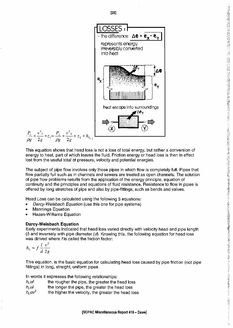
This equation shows that head loss is not a loss of total energy, but rather a conversion ofenergy to heat, part of which leaves the fluid. Friction energy or head loss is then in effectlost from the useful total of pressure, velocity and potential energies.
The subject of pipe flow involves only those pipes in which flow is completely full. Pipes thatflow partially full such as in channels and sewers are treated as open channels. The solutionof pipe flow problems results from the application of the energy principle, equation ofcontinuity and the principles and equations of fluid resistance. Resistance to flow in pipes isoffered by long stretches of pipe and also by pipe-fittings, such as bends and valves.
Head Loss can be calculated using the following 3 equations:• Darcy-Weisbach Equation (use this one for pipe systems)• Mannings Equation• Hazen-Williams Equation
Darcy-Weisbach EquationEarly experiments indicated that head loss varied directly with velocity head and pipe length(~ and inversely with pipe diameter (d). Knowing this, the following equation for head losswas dirived where f is called the friction factor:
h = fi v2
L d 2g
This equation, is the basic equation for calculating head loss caused by pipe friction (not pipefittings) in long, straight, uniform pipes.
In words it expresses the following relationships:h.cd the rougher the pipe, the greater the head losshLal the longer the pipe, the greater the head losshLaV the higher the velocity, the greater the head loss
[SO PAC Miscellaneous Report 419 - Dawe]

[26]
tu at/d the larger the diameter, the smaller the head loss
It is found that f depends only on the Reynolds number and another dimentionless parametere/d, called the relative roughness, where e is the height of surface roughness on the wall ofthe pipe, and depends on the pipe material. Values of typical pipe roughness can be found inthe following insert. This relationship indicates a convenient means of presentingexperimental data on the friction factor.
The dependence of f on the Reynolds number and e/d is different in laminar and turbulentflow regimes. In laminar flow, fis only dependent on R and may be calculated from thefollowing equation:
f = 64R
Laminar flow can then be expressed as:
Q = Jrd4pghL
128JlI
Can you derive this equation?
Within the turbulent flow regime, as velocity and R increase, it is evident that the thickness ofthe laminar film will decrease and the effect of viscous friction will decrease while roughnesswill become more important. In the region described as completely turbulent, f depends onlyupon e/d. The variation of fwith these parameters is shown on the Moody diagram.
Hazen-Williams EquationThe Hazen-Williams equation was also developed for use in the pipe-flow problems. It is asfollows:v = kCRo.63 S054
where:v is the mean velocity, C is a factor dependent on relative roughness, R is the hydraulicradius (area of flow divided by the wetted perimeter), S is the slope of the energy grade line,and k is a factor dependent on units (0.849 for m/s and m).
[SOPAC Miscellaneous Report 419 - Dawe]


I n1Sequation IS not appucaoie TOrlOWvalues or Heynola's numoer. I ne rouowmq nomogramfor the Hazen-Williams equation can be used to graphically solve the equation for discharge,pipe size or energy slope given the other two variables. The following corrections can beused for C values other than 100.
(100)1.85 (100)°·38 ( C )s, = SIOO C de = dlOO C a; = QIOO 100
Mannings EquationThe Manning equation is most commonly used for the analysis of flow in open channels, butit can also be applied to pipelines. For a pipe flowing full this equation is as follows, where nis the Manning roughness coeficient.
v = 0.397 D2/3 S~5n
Minor LossesThe category of minor losses in pipes includes losses incurred by change of section, bendselbows, valves and fittings of all types. In longer pipes, minor losses can be neglectedwithout serious error in calculation. In shorter pipes, these losses become more important.
[SOPAC Miscellaneous Report 419 - Dawej


[31]
Minor losses usually result from rather abrupt changes (in magnitude or direction) of velocity.Generally, an increase of velocity is associated with small head loss, but a decrease ofvelocity causes large head loss because of boundary layer effects which result in flowseperation and extreme turbulence.
Early experiments indicated that minor losses vary with the square of velocity. The head lossmay be expressed as:
2
HL=k~2g
where k is the loss coefficient and is a function of changes in direction, obstructions, orchanges in velocity. k is constant for a given fitting, but varies with fitting size.
Expansions in piplines, produce substantial energy losses. At abrupt enlargements energyloss can be calculated from:
HL = (VI - V2)2
2g
One special case of a sudden contraction is that of a square edged pipe entrance from alarge tank where V1 is O. For this situation:
2
HL=o.5l2g
If the entrance is bell-mouthed, k can be taken as 0.4. The insert table on the following pagegives various k values for different fittings.
Fitting KEntrance 0.5Contraction 0.14390° bend 0.18Gate valve 0.12Check valve 0.75Elbow 0.39Expansion 0.277Bell-mouthed Entrance 0.4Exit 1
k can also be expressed in terms of equivalent length (lId) at a certain velocity. This isexpressed as follows and demonstrates the relationship that exists between f and k:
k=fid
[SO PAC Miscellaneous Report 419 - Dawe]
[32]
Where:!= pipe lengthd= pipe diameter
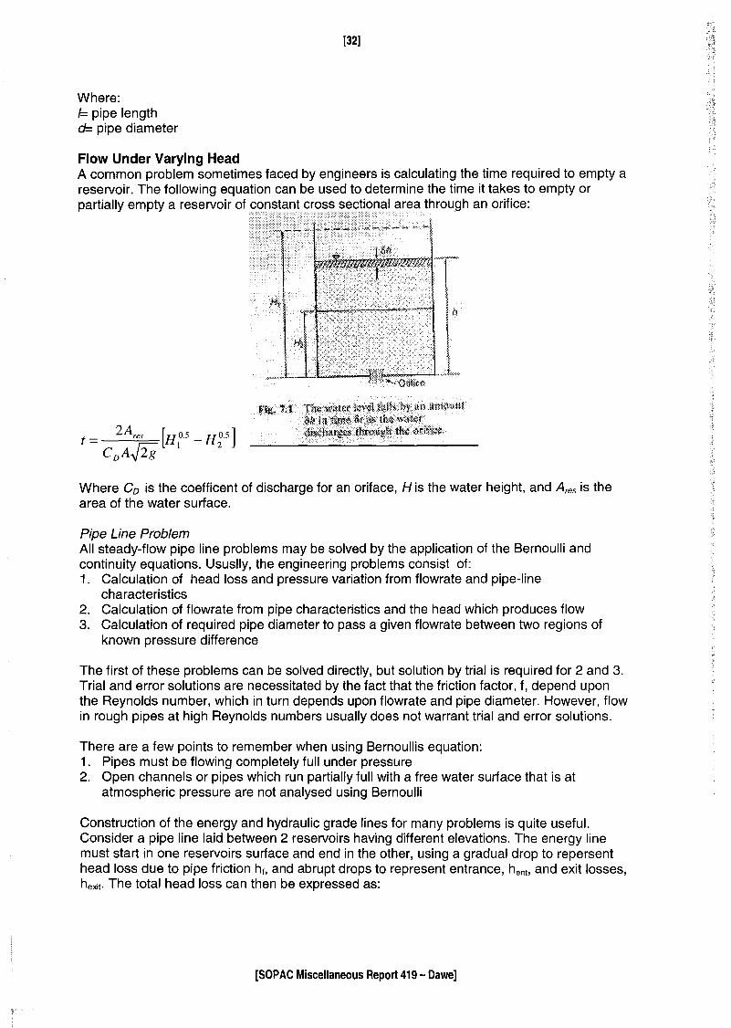
Flow Under Varying HeadA common problem sometimes faced by engineers is calculating the time required to empty areservoir. The following equation can be used to determine the time it takes to empty orpartially empty a reservoir of constant cross sectional area through an orifice:
Where Co is the coefficent of discharge for an oriface, H is the water height, and Ares is thearea of the water surface.
Pipe Line ProblemAll steady-flow pipe line problems may be solved by the application of the Bernoulli andcontinuity equations. Ususlly, the engineering problems consist of:1. Calculation of head loss and pressure variation from flowrate and pipe-line
characteristics2. Calculation of flowrate from pipe characteristics and the head which produces flow3. Calculation of required pipe diameter to pass a given flowrate between two regions of
known pressure difference
The first of these problems can be solved directly, but solution by trial is required for 2 and 3.Trial and error solutions are necessitated by the fact that the friction factor, f, depend uponthe Reynolds number, which in turn depends upon flowrate and pipe diameter. However, flowin rough pipes at high Reynolds numbers usually does not warrant trial and error solutions.
There are a few points to remember when using Bernoullis equation:1. Pipes must be flowing completely full under pressure2. Open channels or pipes which run partially full with a free water surface that is at
atmospheric pressure are not analysed using Bernoulli
Construction of the energy and hydraulic grade lines for many problems is quite useful.Consider a pipe line laid between 2 reservoirs having different elevations. The energy linemust start in one reservoirs surface and end in the other, using a gradual drop to repersenthead loss due to pipe friction h., and abrupt drops to represent entrance, hent, and exit losses,hexit. The total head loss can then be expressed as:
[SOPAC Miscellaneous Report 419 - Dawe]

When a pipe line runs above its hydraulic grade line, negative pressure in the pipe isindicated. Regions of negative pressures may place limitations on the flowrate. Watercontains dissolved gases which will come out of solution as the pressure lowers. Thesegases move with the liquid as large bubbles, collect in high points along the line whichreduces the flow cross section and tend to disrupt the flow. Large negative pressures in pipesshould be avoided.
Multiple PipesIn pipe line practice, looping or laying a pipe line parallel to an existing pipe line andconnected with it, is a standard method of increasing the capacity of the line. Application ofthe continuity principle to branched flow shows that the flowrate in the main line is equal tothe sum of the flowrates in the branches. Thus, the following equation may be written:Q=QA +QB
[SOPAC Miscellaneous Report 419 - Dawej

WATER DISTRIBUTION
Purpose of Water Distribution systems:• to convey some quantity of water to the individual users
Step 1- Estimating the level of water consumption• the amount of water you have to supply determines how big your distribution system will
have to be- ego pipe size• in order to estimate future water use, you have to estimate the future population you are
going to be supplying
Things that increase rn or decrease (,J,) water usage:• population- more people use more water• climate- people use more water in drier, hotter climates (eg. watering gardens)• economic level- rich people use more water than poorer people• population density- areas where you have high concentrations of people living have a
lower water demand (eg. in apartment bUildings, don't have to water lawns)• industry- industrial demands tend to be high, but it depends on the type of industry• cost- people who pay for their water use less• pressure- distributions systems that operate under high pressures use more water• quality of supply- people use less water if the quality of that water is poor• culture- some cultures use more water than others (eg. keeping pigs uses a lot of water)
[SOPAC Miscellaneous Report 419 - Dawe]

[35]
Different types of users:• domestic• commercial (stores, bars, restaurants, hotels)• industrial (airports, factories)• institutional (government buildings, schools, hospitals, prisons)• agricultural
Total Consumption = domestic use + commercial use + public use + loss and waste
Water consumption varies during the:• year- highest during the dry season• day- highest around 7am in the morning when people getting up and showering, lowest
from 2-4am in the morn ina when oeoole are asleeo
The demand pattern is simply: flowaverage _ flow
COMPONENTS OF WATER DISTRIBUTION SYSTEM
Pipes-7 pressurized closed conduits
Stresses Acting on Pipes:• Pressure of water acting on the pipe (remember that the water doesn't want to be in the
pipe and is always trying to force its way out)• Forces caused by changes in the direction of flow within the pipe• External loads like the weight of dirt on the buried pipe• Changes in velocity
Water Hammer• Results from the sudden stopping or slowing of flow in a pipe• The kinetic energy of the water is transferred to the pipe wall and acts to stretch, deform
and burst the pipe• Can be avoided by closing valves slowly for example
[SOPAC Miscellaneous Report 419 - Dawe]


[37]
• You want to break the hydraulic gradient at low points with pressure reducing valves(PRV), overflows, auxiliary reservoirs
• Place hydrants at low points in order to drain the distribution lines for maintenancepurposes, and to remove sediment
High Points• Should be kept below the HGL, otherwise you can get negative pressures in pipes which
leads to the accumulation of gasses that may block the flow of water through pipes• Negative pressures in pipes can create a vacuum that will actually suck water from the
ground into your pipe-7 problem if you are sucking in contaminated water from a septictank
• Flow in a pipe is possible up to around -7.5m of water, after this vaporisation of the liquidcan be expected
• Use vacuum, air relief valves, or pressure sustaining valves (PSV) to release air initially inthe line or that accumulates over time, or to admit air when the line is being emptied formaintenance purposes
PumpsThe addition of mechanical energy to moving fluid by a pump alters the basic energy balanceof the Bernoulli equation. With the addition of energy by a pump, an additional term must beincluded in the equation.~ v2] P2 V22-+-+zl+Epump =-+-+Z2pg 2g pg 2g
Epump will appear as an abrupt rise in the energy line over the pump machine. Pumpstherefore, add head to hydraulic systems.
There are 3 main types of pumps available on the market:1. Centrifugal Pumps2. Axial Flow Pumps3. Mixed Flow Pumps
[SOPAC Miscellaneous Report 419 - Dawe]

Storage Tanks• Used to equalize supply and demand over the long term or for emergencies such as fire• Storage tanks placed in areas of high consumption and low pressure, and will act to
increase pressure during periods of high use (7 in the morning)• The tank will refill during the night when consumption is low and pressure high
Storage volumes can be calculated by looking at daily demand figures. If water coming fromthe source flows or is pumped at a constant rate, storage will be required equal to 15 to 30 %of the maximum daily use in order meet peak demands. The figure below shows the patternof water use for a community. The average rate of use is 41,466 m3/day. If it is possible to
[SOPAC Miscellaneous Report 419 - Dawe]

[39]
pump at the average rather than the peak rate, the pumping station will be smaller andenergy costs will be lower. In order to equalize the rate, the water pumped when use is lessthan average must be stored for use when the rate is higher than average. The crosshatchedarea above the average rate is equal to that below and either represents the storage volumer.t"'\ru li •..l"'t.~ In +hi~ ,",""''U~~''o.+h.t"'\ \/1"'\1. Irno. io c:::n QAt) ......,,3
Dead Ends• A pipe that just terminates• Should be avoided since supply is less certain, and lack of flow in the pipe may contribute
to water quality problems
DESIGN OF DISTRIBUTION SYSTEMS
Design of a distribution system depends on:Topography• if the water supply is located above the level of the water users, no pumping is required
~ this is a gravity distribution system• the steepness of the slope effects the pipe design and velocity of flows in the pipe• water will flow from a high point to a low point, but if there is a rise in between the water
must have sufficient energy to flow over this rise
Users• how much water people use determines how big your distribution system is going to have
to be
Steps in designing a distribution system:1. Flows to each section of the community must be estimated and designated to individual
subareas of your system2. A system of interlocking loops must be laid out-» this ensures continuous delivery of
water even if a portion of the system is shut down for repairs3. Flows are assigned to various nodes of the system
• The actual design of the distribution network involves determining the size of the arterials,secondary lines and small distribution mains required to ensure appropriate pressures,flows, head losses and velocities in the system under a variety of design flow conditions
Design flow:• must make sure that the system operates during the worst case scenario-s maximum
daily flow + fire flow
[SOPAC Miscellaneous Report 419 - Dawe]

[40]
• The design of a distribution system is based on the provision of adequate pressure for fireprotection at the maximum daily flow, including fire demand
There are many solutions to the design problem of creating a distribution system-s you mustoptimise (adjust parameters such as pipe size to achieve the most appropriate pressures atnodes and velocities in pipes) to find the best solution. The following insert helps to explainthis.
Distribution system consists of a network of:• nodes~ points of flow withdrawal• Iinks~ pipes connecting nodes
It is not reasonable to analyse a system up to every house~ individual flows can beconcentrated at a smaller number of points, commonly at pipe (or road) intersections
The usual engineering approach to the design of a looped pipe system involves laying outthe network, assigning estimated pipe sizes, and calculating resulting flows and head losses.The pipe sizes are then adjusted as necessary to ensure the pressures at the various nodesand the velocities in the various pipes meet the criteria.
The calculation of the flows and pressures can be performed using the Hardy Cross method.This method is based upon the hydraulic formulas used to calculate energy losses inelements of a system. The energy loss in any element of the pipe system may be expressedas:
hi = kiQt
Where:hi = energy loss in element iQi = flow in that elementK =constant depending on pipe diameter, length, type and conditionx = 1.85 to 2, depending on the equation used
For any pipe in a loop of the system, the actual flow will differ from an assumed flow by anamount il:Qi = Qassumed + ~
For any loop, the sum of the head losses about the loop must be equal to zero. Thus, for anyloop:2:kiQt = a
The above equation can then be solved for the correction:
~=_ 2:hi
"h.XL,.-'o,
The Hardy Cross procedure may be outlined as follows:1. Disaggregate the flow to the various blocks or other sub-areas of the community2. Concentrate the disaggregated flows at the nodes of the system3. Add the required fire flow at appropriate nodes4. Select initial pipe sizes5. Assume any internally consistent distribution of flow. The sum of the flows entering and
leaving each node must be equal to zero
[SOPAC Miscellaneous Report 419 - Dawe]

[41]
6. Compute the head loss in each element of the system. Conventionally, clockwise flowsare positive and produce positive head loss
7. With due attention to sign convention, compute the total head loss around each loop:'L,h; ='L,kiQ:
8. Compute, without regard to sign, the sum'L,k;Q:-l9. Calculate the correction for each loop (~) and apply the correction to each line in the loop.
Lines common to two loops receive two corrections with due attention to sign.10. Repeat the procedure until the corrections calculated in step 9 are less than some
stipulated maximum. The flows and pressures in the initial network are then known.11. Compare the pressures and velocities in the balanced network to standard criteria. Adjust
the pipe sizes to reduce or increase velocities and pressures and repeat the procedureuntil a satisfactory solution is obtained
TYPICAL DESIGN PARAMETERS
Fire Flows (Umin) 1890 ~ min32 400 ~ max150-250 m0.3-0.6 m/s
~1 m/s
of streets
[SOPAC Miscellaneous Report 419 - Dawe]

[42]
Appendix B:Worked Hydraulic Solutions
[SOPAC Miscellaneous Report 419 - Dawe]


L{ p:. F where p , pfes5ure (:~~) sc lv e -for A ;
A F:: for c.e (~ . "" )s~
A'" o..fe", (M~)
A; £p
As P IClc..fee- s e s Joes A Il'\c.rec..se or dec.rec.se.? ~
As F dec. \ e c. S e.':> do e srI f\ c f e Q. Sf- 0 \ dec.. (e 0..S e '? l'
Co..l\ 'Iou So\ve. t\te e.q..u<thol'\ for F" if A:: 5"",1 QV\d c , ~5 "o.o,?I . S~ .
W ho, ~ do t", e U l'\ ~-\ s 3' \/ ~ you +or P J i 51 t +~e SQ"'" e.')
0..$ o..bov~.
p:= ~ =) F:: P AA
"('~5 ~ ~) ( 5 fl\ ~)
•.•.•5
:: l~ 5" ~ ""s~
Wh~t ty~~ of rnc,.i'-' mc,.1;c.C\\ re.\c..t'lOnsh;p IS there 6etll\le~"p Q.V\d 1\"-
i11 V e r S eli l'\ d " r e.c, t re..l Co.t iOilS ~ .•fl

F- (' sclv e for Ct:I.f F ~ lY\ 0.. w'-'ef e - ",o~c..e
1Y'I = (VIo..s S (~ )
Q= Q.cce\efo..1'oY'\(fV\'\(5~)
Q~ £tw\
w~O\.~ o..re. +h~ un"lts 0-\ torc.e ~
~M.
~":l.
A SO')l ncr e C\ Ses d 0 e S ex ~ 1"\ c, r e.c.. s e 0 r d.e c. r e c.. S e :
t
Whc..1- t'J~e of fY\C\'\\'Mo..1\c.cJ re\C\LoI"\S~"lp '-5 +~ere be.Lveet"\
F G.. \\d A ~
d;rec.t re.lC4tio', s~;p

~ "",~\,' \~e \.~~\" 0\ t"e u~~oo"". side;
t u'l. t ~5 = -,- '1(
~'2..5-1~ ~ 'X
,'X " Jq
" 3
e~ 50°~ W,,~\ is tl,e le",~\" of +,,< hyPotenu'e siJ e, ?
. - 0 12-I '2.. .J'l-v» ~ 0 z -
'X
1(= IS.l
~? W h'd i s He \e~J H, c{' t,'" e lJn I-<no"'. 5 iJ,7 '~1 IoVd'" ihe ~lJ~s+\O'" t¥\C\'''.
e = 'too
~ 'to" = 'X
7
'X -: 5."1-
/"1 whd is t I,e de~«es o~ II,e o.V1~ie ;" ,I;cde J
~ ~ ""dh 0. 'i-u e s t . o. '"'''' If \
') it _~: . r '6
~ 6 •. -'+
e~ (,3.'+'"

A t~.n pi<:<ie I';) c:eVllered I" Q 5up of VVIJ.ti, 0, O("""vJoil.-, cLffere",1
0,15 0\ UI\\'\I\O\"II\ \/ISC.os·,t;es a.lcove a.i'\6 Ioelow: one. \/1.5('oSI1)1 IS
tWice t\oe o{hec vvhe\"l t~e pk~e IS pulled ot ex velocity of O.31V1/s
the ,e')u\~\"5 \orce 01"\ 1",,< of ~\o.ie due. 10 VISCOUS sheen 01\
baH" SIdes i':) 19/11, Cc.lcvleJe t~e v\sc-()s,hes of t~e oi is .
'tz j-A~
J '1 Q (II-s.•...)A~ s.u --'".:J ) """ -,
2.9rJ1. -:: y O,:)I'Yl'j
m O,03fY)
.;U-~.9 ~",1.
-: f' t ~e d Y f\ Q 1111 . • ., c v,s c. 0 Sit'! 0'\ W c,t e r C\t '3 00 c... I ') O. 7 '1S " \0 - 3 sr. s
a Y'\ d t h \. 'l'1 S. 7 .~e. oe05\t\{ IS +G.Oo '1>.-/' ') \.. t t'lJ''''' W'lct I' .J) ~e 1I,r)E'lYlcJ,c v'sc.osdy?
J)~j.A O,7"l3)<lu-'_ :: -----".--. .r 8 ' 0 y; \ 0 - Co (l'Vl -z
.f q~5.7 5

0,\ ",,"T~ Cc ch~V\sit'i of ~I '000 'P-slrm3IS cOl"lto.\l'\ed 11'1 Q 1Q",tI
",J i-, t c.'v, \ :) 'Z .0 VY) \ c (\j Q '" d \ m \tV i J e . Th e de p t ~ of 0, \ j Vj
{~e iCl.v-,I\ I') O.G",.
'" ,~ . t" ClQuae pressure 0\'\ t~e bot1o"YI o{'+l,e tG\",1r1)\N'<c....\ \" V'\€ v \J
"'1 w,",cJ IS t\'e (Nce 011 the loot! Ol"h of the tuV\1r cQvsed
b'i the Ol\~
P=yal, F= P A
" '600~/""'l3 (Cf.81) (o,b",,) '" 4-701 P" l'{IY\~(I",)
,,!t,01 Pt\ ~ '1Lt18 f\/
Wi'\C\~ 'IS 1he o.bso\u1e pressure \1'\ tl,e tQ.VJII:
?0.'0<; '" p <..1"'" t P yH)}f
,. \.OI~\o5P,,'t 'tiO'lP",
~ \0'3),01 Pet
<:.\650101 e
If 't~e [pressure.. ill Q ~'31, pOl',t 11\ Ci. pltJe I') 9'1JSDOP"'J
wn",1 IS t~e.. MeCl.SU~ed) 0\ 3C1.u3e fressure. 0..1 t,,<,J ~op,i?
Pc..\,., ~ P" t "" t P J '\U'jl'
lfC,) soo~"':; \,0\ y. \05 Pc;.t p~"'(]Je
~ ;)«03 e- - \ SOC) P •..•

A + \ ~"' I'" "1M w)'e ClVlJ '3\", kIQ~. It hQIlQs v.u1ica.lly' w ..flre c \ 0.. V"\ ~ L; C\f 3 c.. \ 'C j -c, 0 0 V d , '1
I~S top €dSe \"" below -tl,e wcder SLirface. Ca!c.ulc;1e He piessvre
oT ~"'e 60110(\'\ 0' +1,,, 5G..1e. CC\\cvlc,1e the reSultCii')1 hydro'3+d,c
f0\[£' 0., t\je 5c..1e, De..-ler mln~ t~e depil, c:;1 W~'C.I, th" re::,ulio"i forc(;'
QcJ 5,
I y P~f'rr~ f; f~ ~c, AI",
T .' :: 100() (9,B I) ( It.., ) " 1000 (Ii. 'Ii I) ( Itt) ( 3,., )( < '" )
'"I. . I - 3 9 . , >. P, - '~7 ~ '"
- L_J ",(If-.5 0 . ~,--------1 f -- Q, (3)Z "'Co •• Z ('Lsi +~, 5") lG ~ -l-~-
r: Z. 8 "'" :: l.t, 5

A loci, CP"I Q c.anol i5 seQleJ Icy c.J~1\.> t~d I') 3,0", wide, T(,e
sc.1e IS r ~r p eVlcl, Cu iar to He SiJ~'S o{' f ~e lae-It. Wh~"" th~ loc. II 15
used t~ere IS wd€r Oh One side 0\ t~e 3e-te 10 Q def't~ c1
)·5>),) q"c\. '1,0", on ne ethe.r Side. W~"'t ,~ the hydro..-dG.Lc.
force of t~e two Sides 0\ t~e 5G\le'< A t w\J1c;1 i,ei5~j ('rolv)
t'-'q bed Jo th~ two {orees ac.t'~ Whq,t 15 the l'Y\a~n;tude
0\ t~e ove rc ll resul h:;"t hydcosic.Lc force an +~€. 3cde Q'1d
ut W~c.\ '-'e\3ht does it Q.c..1;
_ JiL_--'ll f,; /DOOC<t.51) (~) (3,5.,) (~.S",)O.o"l)\ I
i -=. ~ 'kN
Ii ~ -I z: \'80, . I:>.:::-~ \ I
-_ -) I . z.o '" _F, ~'i'':t. ""2; 1000('1,'0\) (~1(~",1(:!",)(3.'1)
I~ ----.---...J::,
~ 58. 'I 'P-.N
I. \...
\'1p," '3 ('3.51""
: I. 17 ••.•
hp~; ~(2.0",\
~ O.!"7'N1
FI\; f \ - f\. tc.." ;"'3 lYI 0 1'\1 e, 11"\ S "
~ 1~1.\~fJ '~J.\'R.IJ 'YR -= I~01.IJ(llf",~ t (58.'11\N) (O.G7",)
y~ ~ \."tlm

t\ 5eWe r d \S C ""4 ( ~ est 0 q r ive ( • /\ + t~e e V1d 0 f t~e Se \AIe.r \ S q
clfc.v\u.r 50.1-: wd\" c, dic<\'\'\et€( of 0,("". T~e 5<.;.io<. is ;l1cLhed 0..1
0.1'\ C(V1j Ie of Ltsc to t~e Wd{'lf Sur -\c..ce • lh~ top \?d~ e oC He jC\.1e
Ie, lu,,, below t~e. SV(\<;(e Cc.lcvlc..\e the re5011"1)1 fOfCQ 0" tI,l:'
3c<h CauSed 6y tl,e w",h( ''1 t"".. river Ul'\d tl,(? ver~lcC',1 Jef'-I~
~'(oYn r~e vJo.. \{>( SUf\c..ce. le t~e CECV)ir~ 0-\ pressul~.
~~ lt5"'= ~
,
Ltc'~ It ~ 0 • 'T :(It "'1J
f ~J 8 hG A
~ IOOO('].'te,l) (I f O'~Z4-) ('it (O~"r)
::33(;1. tJ
- i\'tLc ; II ~ It O,Z/Z. Lo - o,DO(,3(' l4. -0 ~_
'i \ - -I- l , 71'1- /lIO./l.Jv.., I,)': .
(, " '\t hYf-s: ~ 'i((D,~)zrI.71't)
't- L'1 ~ 1.7i't-~\.1~1
co 0,00 (,3c.
J). __ -e> I-,~Tl 't~ ~--
1.7 ri;
~t' CO- t . <.. 'Z1 ••.•

f\ surfa.c..e. coV\s\~ds of C\ circle 0-\ fa.d;v.$ '2,0,.". l-t I'S loc.c..1eJ wd~
Its top eJse 1.5"" be-low f~e "",,,,tee SUf\o.c<? C",lcul",ie -tJ-,e. IY\C\'jnltUde
cu'\d chrec.Lo'l 0-<' t~e. fesultctvt1 force O~ He upper Sur\c;(~.
- 'V ~ Fit ~ f' ~ he, A
IiI· 5 '" " 1000 (q, &1) (1.,5 ""l ('2,. I "h "t )
~tt<y 'JZN
~ -"j)" -/---: c, I II~ 2M V'-+- L r;
PH r v -:. :; ~ VtJ.
~ 11?-- );\OOO(~I~\)('2.."I,j"" r-
tf-
";: Co. ~ 1.tVr~ ~F::. I-F1 + Go,lR ~(;;-~ ~
:.71.C.9l..N "tCJ
(3 ::;So. '1 "

A \,°,,100\1 W"'IC'" IS 6e.iO'\~ USed to co()duc.l SOl""le c..Oi'lst rv c i ;0""
wach: 01'\ 0.. t>\ef bvlli I"io t~e Seq ho.s Ci mqSS of 50Jooo~
Tl,e po",iQoV\ I~ rec.1G.\\:}UIQ.f in pla.t\ o..t\d crcs s -sec-LoV). It:5 len3i~
IS. 10,,,, ) lb wiJ~~ 5""" o.hd .i s siJes nfe -:2.", ~'5~ ll,t'. del'1sdy0\ SeQ.. wG\.le, i'j \02S~/rn3. Oel€fmine the \/0\ UI1'\ € of w({ier
d,s,?l(Ace~ by t~e. FD",iooll. Oeierl'Y1'l'1e t~Q dert~ 0-\ ji11l'l1£fSIO'l
0."6 1he.. free b oord 0\ -He.. poV\iool1 .. Oe..1H """'1e il,e 6voyo.ncy
-\or ceo\') f~e pon ioc n •
\J = "'0 000'1>- t.\ ~:= 'Tn.7 <5 rn., ~JJ';J ;: lt8.7'Ot>n3 _- __....lo2..S2 10", (5,."
!M)
-- o.c17(;,(1'\
J freeb ~ '<. - c. 'Fe;,
.r I, 0'7\ IY\
F e- ?~ v
~ /°2..SC9,'i>\) (i:t8',lS,
.: 4"1() '}..fJ

A p\pel",€ (educes jl'l d\c<me1er us,.,~ (\ Skl'ldc.,rd; sym'fn etr\c-~( tc..Pf2(
SeG110V1 o. s 5\'OWh below. c-;Je", t\-je followI'15 l"folMc..1.oV1 J c~lculd-e
tv,e fo~ce e.)(ed€d by th€ WQ~er 0\'\ the tCtper SeC1l0"1:
G(, 0, '\-2 f'rn3/s
o. 't':2"'t7/~d\ s- O.~"" ....,,',~ rv;= __ ~._,~ (0 '1'<f: '''---'--- I, .")10 , 0 '1 I: ,r2
o ~ . '1"" llJ. --> A :A ~~ '1f"l: . '1.
- ., , --' -,--.----- '= I. '1-'1 ,..,.,,/~Pi ::: '2..~.);"" MlC! J
P2-.='1.\j"", \-It,\) 1lJ'2::: O.!f"2..
1/(0,'5)'F f\ t PI A I - P2. A:z. :;. ? Q (rv 2- - Ill,) -e, S .9 rr.,1..5
F" t ·~'t&(O,~Yl.·h - '09.5/'(0.15\2. .,. 1000 (l.'t2~3/s) (S.c,- i.'t-'7)
FR t 70 - <; . 3 3 : I. cr 5 1 Pc,
fR :' - c;, '{ 'k N

A ?\I;>e.I'I\e w;1~ C\ COV1stc..V\\ c\\uW1e~ef of O'~VY\ turr)') throv8~ Q.V)
cU"\5\~ of (;0" T\.,e c.e.v.,tf'~ \.Y\E' 0\ tl,e pipe Joe") 001 c..ho."5~
~\e\lc..T\QI'\. lhe cLsc\-jC\\-5e 11,roV51, t"'e p;~eL()e. IS 0.l"",3/s of
wc..\~~) u..Y\d \-\,£. pressure 0"+ t~\!. 1oe.V\6 IS 30m of w,\.i~r.
c"\cui,,,h. t~E' 1'Y1Q.3nlhde Ql'\d cLrectlQh of 1h~ rEsulfo."t forc\::
e « t~e. ?'pe.I P:</\'1.
I J lJJ
\~/JJ ~1J1_F" ~:_0:_1"",_31,__ ---fl7 PIA, ---'-)~~/~ \.C>.i5)7.7,
~ ~ fRY fl\----- -)
':= I. 't fM/:,
P = 'Z q t :k.P,PI AI - PQA1. 4Y.>-(,D' - FI\A .::. P #;ii;'Z. Q (' !If:<C&:l ~c - flr,j A ~ 'iI(a,IS)>-; 0.07/",'
2.H"~c.(O.()l\",,?J - 2..'1't(o.07\)CcY-l.(,O - f~x ~ 1000(0,1) (1,'tCoo..\;O - 1.'1-)
<'0.9;1 -10, 't - f~ t: 1)-p70
fRx '" \0. ~ If 'l-tJ
FRY - f'2 A'J. ~ bO° -z: P Q (11J1.;u..,..... e)~
fRY - '2..9't-(O,071l ~ ~O :0. 1000 (o.il (l,t ~ (,0")
j:c'RY - I'D.I :'0,12..\
FlZ'l' "- \';5 .<1 'j.fV
_ !L ':1. .'f f\':' 1'0 . 12'; 10, S 't c,
~ C7; 1~.:('2.
f l\ ~ ~ \ ,0 '}z N /0 .5 lj-
6 " bO'"

A lOire of d'GlWleter 0.21"1 1r1c.feoses 3ro:dvc.,\\y to a.3m, If d
a as /\on' 1 of' w-ter h t o.r~ th~ vel OCI+I~S 0..+ '-I~-ec.q((It:'S . s "') W 0.
fWD sect;oY"\s~
0) WI =- Q _ 0.0'5 /}v,\/'5
CD -_~-~.- . . - ~f'1 - n, . ~ z: 2, 5,.,., /'j------- ~, II 0, I
l! --~~... '7 0.3 •••o. ~
1 -------.. : I')J,.:: ..2 ? 0.0'6 rr.,>/5 _
~~, .: A . 1.\3nv,ls7J 0.154.
Wo.1er flows t~(ov5L, C.\ 'oro.VlC~\n3 pipelIne o..s Shown 1'1 i~e
diCl
3fO,,,,. If +~e dlc~me.te\ d'l. I') 'lSOIm~ ) 1lJ't.:: 1.
17!'tYJls o..V\d
f"\J.,.;. 1·'+3 IW-,/s) w\,cd d ;Qmder d") I~ req..ul'eJ for 03
::':2Q~ Q"Id
w~C.\~ I':> t~e ~tllc..l cL,:>c~~r'je c..t Sec.ho" \
;\0.25",/~--- I.n",,}) Q;: Qr AI ~\/ 0 ~:':~b:r,~~~~')~
~3
\ ''\-31M/:; q '3 ~ 2 Q ~
.=: 0.\1'1- """"/5
0, =- Q'l. t Q ~ Q" I1.r A
(d \ <- G r 'I. (j.\7i.t- t: \.'t) r" ~}- , '1. '" "'" ':>
d= Odcn~

·'/c..ter flows t-~ro"'5'" (An e'q)o..ndiY)~ ~lfcc\\nL thc;.1 IS [l')c..lll1ed
uFwc..rch. 0\'\ t~e cev-,trelil'1e of' t~e pipe) f'0il'd J ,s a.31M belolAl
pol'1i'1, Tl,e veloc.itles ale 1))1='3,liM/s o.nd- IIJ'J-.=1.7!1v>/S, The pressure.
Qr ?o\l1t I IS Cj 3 9zP", • wl,c:d IS the pressure cd poi.,f ~ ,(
r~e\€ \:) "'0 loss of eV'\er~y 7'////
~ 1. P '"l.J/ ..P - 0 I 1... P2.. rtf '2.:1'/) ]/I t -. - ~ ~ ::.. t."l. t - t_. . . . / f'~),<;, f 'i1 2 '?l
/-.~-- - i o.~"",
I W / l '1,::'~Pe, C." I \2 p.., (, 7 1)"1-/ --- + J. "'1/5 I '2 --=-- . "" 5/' -------- -:: 0 . .) + -1---
ff1 2..91 Pc,;; <9
O'1't'i5 -o w 3 P2,1~ ,,0. ~- -I 0,1+7
P'<j
P?- = 9.1 ~P9

\11./0.'121 I~ d'a.;()\?d -HoIY\ 0, \o-r3e reservoIr US\\1C\ o, syphon C\s \ ...J ) . St")Own If\.
t"'e o,u3'ovY\. 1",,,, eV\o 0\ t~e syp~oV\ p,'pe 1"3,-:1.,,, below tt,e wo.i e: lewl
in t~€.. reS~rvod, A t t~t'. h,~~e6i f'Qrl- of the Sypho,", f~e. CE'f.fer /.nr
0\ t"'~ pipe IS Q,?>"", 0,60v<:> t~e lNo...ter Sud'qc <0 , ne p 0- I_Ii e '14S
0. dl<A"'Jeier of 2,00 'Yln.., Qnd Ii c!I.schv.rses to the a.tV\')osphere. Assu1
"Y}If)9
t~c.. t t~e wcder leve \ 1"\ tl,e reServoir remC\il"lS Consiq",i Oi')J t~q t
t~ere Ole no enef~n losses, c.olcuIcJf' the d.lsc~Qr5'" throu3'" th€.
SYfIJoYl OVId tl-)e ~ressure heo.cJ q+ t~e cresi of' t~e Syp~Oll.
J ~
~- -- - -- r ~.' ~ 2, t ~o" ;¥'0 _ "",0 t !o t,,"-'-'--"---fh \\ 1 J'~ '6 - f~'~
, '\\ I 3,1.... 3.1",., = ru.,. '"'-----.J \, I '23_.
'. ~-- ...J... •
J. . -' q .••.•r' flJ" - 7 ,2(>,+o.'{"'" - • J
Q 0 flJ'lf'7- 7/j(} +;;0 ()J.J U P3- /I) '2.
- '<- 7' t -/--- -:: L?r t - + -2_- 711.""/5 (O.l"h-,) '/I ~ 2» y~ ~3
::- 0.1.5"",,1/5 0 ~ 'Z.3,..", t- ~ t (7."'12-",,/:..)'
f'CJ -Za
P3 ; - 5 i :kfCl

'ole-te\ (lows LH'\Jer C\ \/ertic:e.\ Lft 3 C\ioe C\S S~OWI\ be. low ' T~~ depi ~
0\ 'weder U,?~dl~YIh IS 3.1-"" w~l\e d.oW\13treoVY\ or -t~e 3cd~
tt,e d.e1't~ I" 1.2"", The veloc;ty c":str;'bution upstreQ""- 15 'tulfe.
uy)'I\ollY).lhe chG-l\nel IS Lj-.O,'Y'\ \!VIde 1N1-t~ <\ horiz..o"tC\1 bt'd, ASSUYl1l'J'j
f)o loss 0'\ e.V)e'5Y) vv'hc-t 's t'-1e.- d,sc\-'a''je?
-I -SL---J." ~ A \ I\J I = 1-\ ':l. tV'1
i I, I
3,'t""! ( -/----- _ C3,'tIln)(lt"",,) I\J, :: (1.'2"J('t'W"l ') '11'1-
! I L ~"'" flJ, : O. ::,53 'IT <..
- !--'1. 1-
7.. rv \ I\J1 t- - :: Zz t a,;z -~ ;z~
3,'t'h-\ t (0.")5)'15<2.) 2.. 'lJ:L'---- i: \ 2_ T --..,-
~~ ,~
O,z57')I\Joz."t,
= 2,2 ""<--5
7.0flJ'2. = ~ """/s
Q -- Itr A
: <..7.0 ¥Y>fs') ( t;- •... \.1."",)
~ '3 '3.<;, "'n 3/5

f\qJeo..~ 9,.uestlOI'\ USi()~ CO\\ec..tIO., f"cto's. T~E' VetOL1t) cLdr.bvho'i
IS U'{1I\OIrY) 50 J.-.. ~ \.10 bu1 there ISo.. SijY'lICCC\V)t VQ';C..110l,
do 0 w Y)str e Cih-) 0 {' t \-t E:- 3 cJ e, S 0 J... 'L; \. oJ 5. Who. \- \ ~ Q? How Joe;:, + ~ I 'j C 0 \'>1Pq '(r :
L:-!li ~ ,. A~~:'0,::::I . .--/~ I
. , 1. 'l..L .""""\ nr, (1J
1--- 7, 1" 01-1 -- :::. 2":l- f- cf-.'l. _2.2~ 2~
wid1"f4-"" . (o ..~S )'lJ::l.yl.. t.s "-3,'tT \.\ . ;I;: \.::l. t- 1.55 -=-
z~ ~~
n.J2; S:=.i3 ""'IsQ ; /\ '2 IlJ 1-
" 1,1. '" • '+ M C'5. S ")(h,J s )
- ~ (' -' J/- ~"",5't."vI 5

\
~\-nd t-~e timp to eW\r'ty o, to..l'\t c; Iv) sq.,uo.re une\. '2 t'Y\ deee '1hrot.J3~ Ci
2.0c!W\ or;',C;.,C\i' c,,+ t~e to,"l K bo1ton,.
V :'l.", ~G."",c,,,, r--- Q~ I1JA'lJ:o J 2..~L~., . . ~
-e 7 2- 'M '> : (,.21;, rvv, {s (0 14) fr
~ J2.?J (2. ""'I "Co o . I e, 7 rn., J 15
z: G. Q.G "'-1/5J ~ .::L =. 7 2 'Y>\ '. •
q J - 3(; S s(j·\"t1~/5


A ~Ipe 6f d'~lYie1e{' 0.\"" ccrrit'S vvcJer c.t the. fute of 0.0<'5",,3/s.
To.1'\1'''3 t~e.. deVls.ly of t~e Wc,1er as 1600 ~J'Ivt) QVlcl Its dynqwlI(
VIscos,iy 0.5 1.00 S)\ 10-3 _~ 1'Ivl-s I CCi.\ cule.te t~e- Reynolds nUmber of
t~<::' flow OV'ld Je1erlYill)e whether It is lo.minQf or turhuleV1-I,
RQ '" j' 115<:\ Q t: III AfA (lJ -x o . 0 Q.S !WI }J'j
----~-z. 1000 (3.\8/h1)sl(o.1 ""j Ii {O.os"",j'l
\ .00 S '!- 10-1 -:: 3. \ 8 ,.,."Is
~ 3 .il;, ,,10 5
3,\(;1-!DS >/1'000 :. flow I'::> turbu\~V\l

"[wo rese.rVolfS are connected by Q ?ipe\illE'5 as sltoVJi'l' \\'e d;{'fereU\ce
I'" ~\'e- elevQhc\, of t~e \)JQier SUffGlce betvveel-l upper O..l"J !ovV(:Or
res e c V 0 \ f I 7.-) i ') C0 v, s -I Q ",1 a ~ 15 0 I'" P ; pel if\ e S 0..f <2. (0 1\9 ) : • (' ric i I 0 '"I
\ o s s e s do {\"I\i'\C\~e ond (i\1"Or loss to '5 CCln 6 e i 'jl"lorec\ , Co.! ClJ Ie, t E' t~e
c\ ISL'nctf'j€ t "'ru <,:,o.c\' ? I p<;, 11"\(' •
cl 0 t. ~ """ Pipe I
\
9 /'1~\ .. I T.. 7.."~)
~. . IS':' •.•l__ ...J--------....~-__. (> " 0 ·t.
~ _------~__ I~.L ISo ~ ~!!- ~J-Cl.'1.,., - I I jL..----J o I ~ ~
Q~l.tJ~o oO,o't ISO:: O,Ott ~_"" 11I,1..
c1,1"'" '2~
05,~· \. "t 3 ') "'1 I ")
Pifc.l
Z. ~ 6'-- X2. f\S'L1..
d1. 2.'1lG ;:: /\ i IlJ I -= II G, ':I. I 'h, )/)
\ 5():; o . 0't '1- 1; OD0 "'" (1J1. (--- ----0"1"",, 211 02. r 1;,.,7.JU '.!- -c, 0.78 '1.'\v, '15
n.J'l :; 1,1.'1" l""'l/)


A. flf'e hQ.s c, d.;~l'V\e1ef of 317.5 m"'. How J'l)oc.\j flow c.a"1 +";5 plfe
cG,"Y If the a.lIowe-6Ie hea.d. les s 15 '3.5~ ,',..., a. le •..•3t~ c1 <.O~:
T~e. ~ipe is steeL 1) =- I.007 )( 10-<;;
,Q,.,. 0, C06 \.-:' .IL O. 00'3 fl \~ 11\ - ;: z : <5, 00 Do '':l..
~ o. co 3& \ M'" Ii '?lll .5
8 ~ ~ O,OO?J11- ::lc ° .o~
A";)suV'f'Ifi! 6~O.Cl
f\J =-~1- :( ~ d _ 3. Set) ('1 . '0 I) ( 0 I J 175)_ - z: 3.3 ° '"Js
L e ~oo (0·°1
N l\ -e IV d ,.. ~ X D. 3 \ 7: . -:: I .0 4- X /0 "}J 1.001 )(ID-"
At tJR" I.olt )lIO' t 6'" o.Oj~
re<.«.\c,;;) t1J: 3.0\"'/~
NR:= 9'1"")/°06
8 ~ o. 011-
Q = nr A(O.3i75')~
e- 3.0\"'/5 7i ~
: D. ~ 3 $J '" '3/5

Pc. -= \. Z "'"
\-,c. --5.5~. ~~._ \r/hH~\~)t~e.. h\j~l'__('_.,;t,.,_.o-,!~/- . d" ~O~3~:~'\--r""1 "~ ;,": :,' VO,,: e \i:::: eO \" ~w:\A \ ':: C;\O"" '\\\.' '-.,;' p~ 2._) IS t~t:: flolA) fc..rtc 11'\
j.." I. 5 "'" '>vi '-1 -\~E' t' \f e. ?..~1__ -
() --
\)e( o o vll. 6e\weeV\ 1\ aVId ()
o
~p o ~) 0 f;' 'lJY () iJ Q 'l.
- t' -;to. t ~ =' . 1)?-;, + f ·t B - ~- C(\ 3 '0 2~ d- Z B
I --
J/) 'do fro.", fIIIVGdy-OIc<,sro,"'1
f1}= ""'fjl'"l
~ C? I.S""""Q .Q. _ ;:-"" • 0.005c\ 300""'"
2. ('1,01')(7.(:,,,,,')(0,'),,,,)-z: - -------- =) g-=- o· o~ e-cn tl) (b u Ie V\ I no .
0, 03 ( <; 10,"" ')
-:.fi If- 't" eM /5
:;. I. S6'1vl/s
~e; I\Tdf ~ IS(;""1/~(O';.",,\
LA -'"/ r • 3 .~ 10 =) foe 100 C
:::3.{,,,:IOS
(l) e~novil-, be~weeY\ Aa.",J c.
?~ ~v 0 p,,- 'l..
-.--- t "10. t ;z:. " - t ~ t- h<.. + 8 -! '1J '"
f~ ro feo 2~ d ~~
j .01 1I I() 'j p"z; 5.S"" t- 1,7,,,,,,, 1"' (I.S(;I\'r,(s)"- ( 9.. .: \
JOW «L'OI) - I + O.D":) -3)Z'D o .
,9.= '1S(,,,,,,,
Q -= rv 1\
- / 'fi (0.3)'r: \.':)(;<)v.'5_
'"j-
; 0 .\ \"""';/')


GiveV\ tho.1 0. new Co.s' iroV"\ ~'Ve- corrY\Vl5 wo,1e, 6etwee.YI tVJo reservoirs
\to..s 0- diClVY"le'e.( 0\ 't I" o.n6 t~cJ t~e. s\~~e of t~e. Q.l'1
ef3Y
II"'€. IS (,owt/loo0t1) VJ~o.tl') i~~ ~i5c-\Jc;r!Jl::::
\)5;1\':\ \"\q"Z.~V\- WI \\\(A\IV\S rlOmc!j\(A""I
Q Ice ' O. 5 '3 ttl'ls Q ~ Q (~ \c 100 100 )
C~\J,O "" O.S?'~)/s(';~o~)
." CL G '1 e? '/5
A p'o..S'IC pi~e ~o.s -to co.ny ctf\o'\I\l 0-\ !.S ~3/S QloY1<j 01')
i"c..\I"1~ 1hc..l ~ IS 20 &t below CiYld 4000 eJ owc..y
f (OM t~e. Sov(Ce to.V\" • W\"'o. t .s t "'e \> Ipe d i4\'\'\e. ~e( :
slope co 2,CJ eJ • .-t; _ ~'tOODt-! .~ - IOOoeJ
f(ov\,\ ()0 \V\O~r 0.\'\'\ '\ C' 100 0.)'0'o 1£6 -z: (0 Or) ---'\
I ::,o )
d=\O~l\-=<t5,S7;"'"
C~ ISO

F;\\6 t~e neo.6 loss t\'fov5~ three. 'ioo e.lb o w s I two 5cde- vc<.!veS qnd)
0. 5.wi,,'j G~ec..\\ "c..\,,€. In (A \~-I,", due-t,le ,fO" ~"f'e cQrrY;l')j c< flc"'"
0\ 0.::' m '1", AH,CA 0\ \" pe- \ 5 o,u'n"ll ",,2 . '1"- (0' 7- -t \0.3'1 ~ - --'f)v, 5
l\ e.\l?ow ~ '2~ - 0,0/ ~'11 ,')v,"'"
\I~.A\e vc\\v<: ; 0,\< ~ tJ.&I). . _ - 0 8b<- 'It c~n\\ Uc.\ve '" 0.1') - ' ""'f
0.'0(,<"»)r-
r o,3<j J rv "-\-h. -:> L3 W) t ':2 ( 0 _,1') to. 15 ';:-;
~~~
~ \. f5 5 f\'\

'rlo.tel ho.s to be. dIs e-I-)ar'je.o. o.t the_ (dE?- of \.'6/M3/$ f'rovY) 0.. I Qrje
stO\fl'\ \Na:\e __ deten t;o\,\ fUl'\K- iv"do tl-)e Sea.. V'O- Q.. S ub mer 3(:'. d
ou~ \0..\\ ,The flpes ho.Je c.. fr\c.J~Ol'\ to-c.."tC>f" f of a,0t- a.Vld
l to -l-IQ. 130"" lo\'")<:.\ p,"pel;"'\2 IS s\,qrp. CQkuki€.- thee~\ro.~ce In, J
\ t- 0-\ t~e wde\ surfa.ce 11"1 +(,.,e. de.te.r,i-lOi\ to.Y\K' (Q.sl)e eVe.. ID"'-
" \ to obt~i", tl-te ne.cessary d\sc.lrlaf~~ if t~e. oipe [1"Mefeq,.uI.ee r
" '. 1- -\. \ vJ;+~ o, lJVl,foll\'\ J,io.!M€- ter of' o. ctrl'\.IS COVIS \ ruc..leo
+? \ -po rv1..0 0 po flJ'2,
z.. t- i!: t- ~ x: ~ 1-- ~ t- _2 T ~Ll-~ Lk ~p ~ 2~ ~ -:Z'D ~ i7 _
_ rt.J~1.. 'L. 'l. ;"l \ = D,S - + 8 --!L V1- "t 1\J2- j .'(;"." /~
~ -.l - -- l'if"')a- O-.2~ 2. ----u ~ (O.'t5)zli'
'l I ; ( 0 1St 0 ,0 If- I30.,., t- I) C!2.·B"'"'Is) '"\0.'1..,., l.ca ::- 2.Srn,!-;
LI ~(1.2.8') o.t
~~.CJ~

',I",~e\ tlDIVl o, \/HTi'Co.\ly 511<:6 recJ<AV\3lJlor taV111 3m by Zvn ;h plq"
(hsc..~ar~e') t~rDLl5'" c. so 1Wl"', d,Ct\¥)etel' NleCt loca.tec\ 1'1 t-~e_ 6C\Se
T~e Co of t~e art'flee i s 0,(,1, If t~e depl\, of lA'Q1er
i" t ~ e. t 0.11\\ i5 \ nit i0. II Y \ • S "'1 ) it D W \ 0 Y'ltj IN' ill Itt q 11'< f'0 r
rhe. to.V\\\ tD ~VY1f'ty;
Aws~ 3-1.. "2.-Teo 2'G"" r '';: C, "'" ~ ')" _ I (I. S\:t _ Ol
(J,(;,I (0.001')(; ~ I. . I ,-,..,\ J/}'Y\ v? . '1.'81 e-
A" 7i (0.01..5)'2..~ '2.1,5')
.;: 0 ,00 \~ Co "., z= It c;, . 'L$ """"'"

\-----175 e=o.o't for the fo\low"rlCj syste..l\'\) wl,(\.t
" " ce the flo W s Ii\i" e i \') e o,e, ~1.----.-.....:"o H.
5"0..... f' ~ e b(c.Y\c~?G 'tSOm
~-- __ -J-_-I5~l)
1----1 n·SfSO", ••
-_ •...•_11.5C.
A-D-LA ~ "Z.0 t h \.AI'> l' h~e.\)
ll. tv '1. (tJ~75 -30 ., ~ d ~ t ~ g..!..2.~ 1 e a
I'~Oo",... 1,
'+S" o.o» ~ t ~ Q.O't ~O·in, <e ~'O o.DSm
1.t5: 'l..tt.Sru-f\I!>~ t" ,'O.)(U"6D~
l.\-S:: ~1.f.S (~ \Q t 1%.3 (Ql?lO )~'it' fo.os)'! ) It (0.0.25)1,
itS ~ VnJ111 QA6'l1 'tlLtc""C;S Qel)~
Q~o ~ ( If 5- 3'11)II'} Q"""'':l..)O'S't,II.t(., 'CJ5
Q A\}; G eo t- Q I!> c.

A-c.- LA" Zoe. of ~L."c
75 = 11.S t e ~ N"e"- + 8 ~ 1Ire,<:. ~
d 2t} d -;;
c;;~.5 '" o,o't \~oO•... NAB'>. U. 3000 •... Nile.. '1._- __ + 0,0, __
0,1'" 2'l'l 0,08 "" ~~
G z . 5 = 2. 't ,I) or.A B ~ -t 7 b. 5 ,11"Be. ~
GV;= 'l..'t,5 (QAB \'< t u..5 (_~rK \'.2r.- (0 -):1.) '7i (O,Olf)'" )I, ,O~
'2.5:'3"tlJI1~Q .•.~1l. ~ 1?-'t()J171~e,<:.'t
\ 1, 1..CcQ..S '" 311)111 CQe.o tQG<..) + 1)'<.'+0)171 QI3c..
Q
(
Co '1.)0.5P.e;: G2..S - 3111) II, Q"'I;
1)~~0)\11~
Q A11>::' (It S - 3 ~1J 119 ~ M '1. ) 0 • 5 t- (b ~ .5 _ 3 ~ 1, 17~ Gl'" ~ ) o .S
't)1't",~15 1,~'t0fll'
0,007, c: 0.00113
QII" > 0,0011 _"'>/5 • 3"00 sf..,; 1/./2... "",,"'I,
Q i'.> c.: O. 0 a 5 t;, 1M ~ Is Q eo=- '2.1 . 1 2 ,.,.,~r '" - 2.°"'"}I ~-= '10 ••....~ I "'-= 7. 1~ fI"to,' I~


A systel'Y\ re."l-uires '2.5 "",3 of w,der I~ for Go f,'pt? line. 'tOOO h., 101"\9.
The de.\iv(.(y po,v'd is I~,S"" IOINer th""", the $oufc...t:. Pressure at
the. sUffly SOUrc.e is 75..,., Q.l'\O re'j,uirl'd flfes:;ure cd delIvery pO;l1f
is 2.5"". WI-)c..-\ nOlV"l;",ql d;o.l'lo1e1er q",J c.lc s s of' pvc pipe is
req,ulfed ?RL.7S.., If'1'S""
RL.0 1---,1:1..,- RI- ·12.5••.."'3
Q ~ 15 ~ (IOOC '-/'M3) ({\..-IL5",
,. '.9't LIs3<;,0() sIn
u - 7 c ,.,5 ,., 5 l"'\ C;~.S "'"'II\..- .:J,Y\- .•••.•.• +- I-c.. '" - ~ = 15.C ••.•
1000"" 'toeo= C;~,5"" ,., 1000""
looc W\
-tco..... .flow res', stG.r'\ce cho.r \ -) ~ ipe clIo-meter betweeh 80 - 100 """I.
USe.. 100 P'l1'Y'l
MG..y' hea.d = 75 r 1'1.5 •.• = 'isl.S""'"
C\c;.~5 C. Fi~e
-fa' i"'~s p'fle::) HeCA.o loss = G. <. "" .., r h t":, "' ro",", c.. qr
1000""
t, 1 I 'D"1.5 ""o.\\oWG.ble. "ec..O' OSS = c::. /=- ':l. I . 0 '" , OoD ..,.,
,+000",
1000",
IOum"" J c.. C-Ic:..ss pipe.:. ,,-ppropr;<:<.1e

O·'5c..~o.rse. reet.u'reJ is 2S ••.•3 of """,te. per hour for a. P'fl ••.tine. 3000",
loi'\'j' T~e. delivery fOlrd 1.5 11.'5 '" ~i3he{" tha.1'\ tl,e sourc.e. T"e heqd
o.vo..'la.b1e e.-t the 50urc..~ i s 7S", and tf)e. re..'i-u;red discna.rge heCld
is 2£", ~ Pi pe line. ho..s:
3· cl who.t f'lofMc..1 d,C\meter o.fld c...lQ.s~ cf' Pile pipe 1.:\
'lees - ~ o.~o _ -,?re~U\reO .'3 scour tees 1- :: I.D i;JU R\- 37.S Q:: <; '1 '-f
7S'" 105M • .5fl.l. l~. S
It 700 'oe",ci 5
't ItS 0 be",! s . floL 0Pu •••p
A 5S u V'1C: I00 IY\ ..., pip e
Fro •.•.• E'i.u'va.\e",t PI-P~ leVljtl, +c..b1e
3 JOD""", T :: '2.7", Toted e'l.0iv<;.le",t 1e"5tl... of" plpelifle
3 10o""", 5(,00(1 = 3.'1 •.•••. 3 DOO...... +' :2. 8 '" ~ 3013 M
\i- leo",,,, 7Clob~hc! = If.'h"
2. 100"'" 't5° be"" e I. '0 "" l f l des5 0 'Ie eo. :: 7 5 - :z 5 - 11 .<j
1<. &'" _ 3 '"- 7.-,"1
M 37.S...,- s: fY\o..X heC\.d :: 75 n-,1000...... ,,(2 ••.•S""'/IOO()'"
3 013 ""
1000""
100 l'Y\ "" c.l c..:> 5 C..., ; 0 e ) r L ~•....I :: ,rOM c,••eo.f I
c.. ':),•....l.... a.IIOwc.\:.\e hec..d. loss of (2.,+$ •.•..•/1600..., ."; cit
1000"" )

\.}h",,\ ie;, th~ MC>.){ifYlurn stress ""I"e.'" could bQ produc.ed in 0. plfe
""I\h dio.vneter 5751\'\'" 0.\'1<:1 ""e-ll th.crrneS5 of ~ 17.5"",,", co.rrie 5
0. (low of 7Cjlf t.-/s o.S a. result of SUdJe"ly c.lo s , •• ~ 0. Vc,,\ve II)
tl-t~ \i,,1.': ': (\\ \01" wG.ter IS loy of' ~"'e vo..llJ~ of ~ tOI '0 tee I.')
[I JO•5 1lJ- ~
PI1 = .5' nr I d .p(~ 1--) d-p'pe Jlo..vne1e,
E)t - f>ipe 1rJ0.11 t-l-,i~lIl')e.ss
€ :. 10,OCO MP~ 1\ - buill modulus of elastic.it" of ~cJH
E - Mooulu~ of elo.s1ic.;iy 6t f>ipe
p11 ~ ((000 '"YJ) 19't t, Is [ I ~ o. 5",,3 10CO= r;,.11(O.515)" I '0..•. I 0,57'),,,,",,3 -- 000'-' -- r _
1. ~ (1<'<00/119 (IOlooo;~P)(O.OI75 ""'))
[
e. y.gz: .30 5"7. 1 '0". q '1""0- ]
, ') D:JC>S~ Ie,
:::. 14-77 ""p'\.

Ffo", th<2 followil"\3 hourly derY'Q.nd ti~u('e..sJfit\6 the uniforM f'0""f>ln5
ra.~e whiLh will just meet t"e. de.rY'a.nd and thE! volume of stofQ.3e
re'i-LJire.J to m~e..t vno..X'rnLJrY\ hourly defV"\Q.nd.
TilYle.. Ra.te. ( •••3/",,-.'1) Time Ra.te. (",,3IM',,)7 .~ (1\001'1) 11. '2.3.~
C•.• ;Jn,~~th ~. I '2.'t. '5, 7. i ~ '2.'t.""
'J.. 7.0 3 '2."\-.Q.
3 7.\ If ':l.t.1
'+ 7.0 5 '2.5.C.
S 7. 3 C; ~c.. 'l
Co 7.S 1 3't.O
I I<.Z ~ 33.0
3 1'0.'1 q '2.0.0
q ~1.0 \0 '6 .•.•.
I0 2..~. 8 \ I 7 . C.\ I '2. 3. 'S
V ,.. 3c ~Stor"5e ,. 'S '5 \ ""

By interpolation, frictional loss is 5.1 mlkm for a flow of 2.3 lis. Therefore, totalfrictional loss is
2038 x 5.11000
= 10.4m
and the height of the HOL above the water level in the tank is 20 • 10.4 = 9.6mwhich meets the design requirements of Sm minimum.
Three Hour Practical
1. General
This example is taken from an Indonesian project operated by CARE3. It can beused as the basis to create a worked example for a three hour practical by alteringparameters to be more representative of conditions in this country. Participantsshould follow the step-by-step design procedure outlined below. .
A village has a population of 850 divided into two parts, Part I with 60S personsand Part II with 245 persons. A water source with an estimated minimum flow ofone lis is located approximately 2,300 metres from the village. The standpipes areused for 12 hours per day. Assume that galvanized iron pipe must be used for allpipe because of the rocky terrain. (A sketch map of the village and a groundprofile are presented in Figures 3 to 6. Design the pipelines required to serve andplot the hydraulic gradient for each pipe length.
2. DesignParameters
Population
The design population is the expected population in 10 years at a 2%growth rate or 850 x 1.22 equal to 1,037 persons. For design purposesthis is rounded up to 1,050 persons.
;
Water Usage
It is preferable to supply the maximum amount of water possible but aper capita supply of 100 litres per day would require 105,000 litres/day ora flow of 1.21 lis. Since the estimated minimum flow of the source is only1 lis this is not possible. A per capita use of 80 litres/day would requirean average daily flow of 0.97 lis and this is possible.
Storage Requirements
A per capita use of 80 litresl day means that the average daily usage is 80x 1,050 or 84,000 litres. Because the galvanized iron pipe is so expensivethe smallest pipe possible is used. In order to reduce the size of the main 17pipe, storage will be located in the village. The recommended storage isthen one half of 84,000 litres or 42m3. Based on the present populationdistribution 245 + 850 x 42m3or 12.1m3should be in Part II and 605 +850 x 42m3 or 29.9m3 should be in Part I. Based on the village sketch ithas been decided that the water will be distributed to five publicreservoirs, three in Part I and two in Part II. With this layout, the waterwill be under village control. Costs will be reduced because the main pipedocs not have to convey peak flows of water. The public reservoirs are tobe situated on high points to obtain any acceptable pressure head at thetank outlet.
The three reservoirs in Part I will be 10m3each for a total of 30m3(rounded up from 29.9m3). The two reservoirs in Part II will be 6m3 eachfor a total of 12m3(rounded down from 12.1m3), With this distribution ofreservoirs, no one has to walk more than 100 meters to obtain water.

Number of Faucets
The number of persons per faucet should be between 30 and 100 so thenumber of faucets for Part I should be between 6 and 20 and for Part IIbetween 2 and 8. In order to accomodate future demand, a higher numberis preferable. Thus 6 faucets at each of the three reservoirs in Part I and 4faucets at each of the reservoirs in Part II give a total of 26. The C!vq".,'C
number of persons per f'aucet (based on the future population ..42 for Part I and 37 for Part 11. Half of the faucets can be placed 0;' oneside of the reservoir and half on the opposite side. Thus, one area can beused by females and the other by males.
Design Flows
The-path of the pipeline is sketched in Figure 3. The water will flowcontinuously into the reservoirs so the design flows will be the same as theaverage daily flows. The peaking factor is therefore 1. At the projectedper capita use of 80 lIday the average daily flow is 0.97 lis but the springhas an estimated minimum flow of 1.0 lis. Therefore, 1.0 lis will be usedin designing the pipeline.
Figure 3: Path of Pipeline to Village?
18 From the source to the junction at point A the design flow used is 1.0 lis.At point A this flow is divided with 0.7111s flowing to Part I andreservoir B. The remainder of 0.291/s will flow to Part II and reservoir E.At reservoir B 0.23 lis is taken and the remainder of 0.48 lis flows toreservoir C. At C 0.24 lis is taken and the remainder of 0.24 lis flows toreservoir D. At reservoir E 0.14 lis is taken and the remainder of 0.1511sflows to reservoir F. The design flows are noted on the pipeline route andprofile.


[43]
Appendix C:Material Not Covered/
Material for Advanced HydraulicsCourse
[SOPAC Miscellaneous Report 419 - Dawe]


~"'''''''.'i I
\ ,\ . II\. .1, .1 ::.-',_~
" •.•. fAhlt •••••••••. JddIIn,
li~li~l1tData and Instruction SheetWf'i~\'/'iL'~<'~ri~stru~tions Data ".
Read the following information and refer to the map and NO!E: The follow~ng are hypo- .~data to find the best locations for the untreated water line thetical costs; they include mate-aand the wastewater management plant. rials and labor. Contact local .•'.
engineers, treatment plants, and ..•.Untreated Water Line construction companies to obtain]
o 0 costs more relevant to your '"• sketch possible routes for the water line ity .~comrnum .q
OJ• calculate costs for each route;~
o • r' • untreated water line (runs '.~• assess environmental Impacts or each route f 11fi ld tit) :;rom we ie 0 p an = ~• use the above information to determine the most cost- $12/foot ($40/meter) ]
effective and environmentally sensitive route 1
• main sewer line (runs from .;Wastewater Treatment Plant sewer collection point to ~
• consider pbcing the wastewater treatment plant at wastewater treatment plant) = .~each of the six desi~n(lted sites on the map 0 $9/foot ($30/meter)j
• assess the best location based on the followmg: • wastewater treatment plant = '.~- costs (of running a single major sewer line from town $45,OOO,OOOi
to the plant) :~- environme'.'l,'l concerns (specifically. proximity to • easement on farmland = .i.~.•.
discharge SIte [the river], direction of streamflow, $1,000 per linear mIle;quality of ground water being drawn into pumping :0wells, quality of river water that could become part of • construction of lines underthe ground water) existing two-lane highway =
- legal placement of wastewater lines (it may be unlaw- $100,000ful to cross wetlands, public property, state parks, or 0 f liwildlife refuges) • c?nstruc.tlOn 0 I.ne to cross
o • _ rIver (this comphcated proc- aesthetics and health Issues (including odor, down- involves permits and complei,,;
stream flows, and landscape considerations) ing environmental impact ~~• use the above information to determine the most cost- statements) = $500,000 );
effective and environmentally serisitive location. • construction of line to cross
Prepare a presentation for your classmates, including existing bridge = $50,000reasons why you think your routes and sites are the best.
• construction of line to crossI wetland = illegal
I
Il ©The Watercourse and Council for Environmental Education (CEE)oIi


·BASICS OF HYDRAULICS - P u M ~ 5
Flow and Total Pump Head
A pump is defined by the flow it is capable of providing (in lis orm3/h or gph) and the total pumped head it is capable of deliveringatthis flow (expressed in meters).
"
TPH represents the difference in pressure between the inlet andoutlet of the pump. It is equal to the sum ~f the geometric elevation
Chapter 9 - Page 1

PUMPING SYSTEMS
between the well water level and the pump (Ha)' the geometricelevation between the pump and the water level of the tank aIr)plus friction losses in the pipe: TPH = Ha + H, + friction losses.
Friction losses are due to the flow resistance of the fluid in thepiping and its accessories such as valves, flowmeters, etc. it isexpressed in metres and fluctuates in proportion to the square ofthe velocity'of the fluid.
Increasing the diameter of the pipe will decrease the fluid velocityfor an equal flowrate and therefore reduces friction losses.
In well pumping, two water levels are kept in mind, the static level(no flow conditions) and the dynamic level (pump in operation).The dynamic level varies according to the pumping flowrate.Therefore, with a higher flowrat~l()wering the water in the well, itis important to size the pumpmgsystem according to that levelwhen determining the Ha.
1
.
Cnetner 9 - Paoe 2

Hydraulic Power and Efficiency
IHydraulic power is the theoretical power required to move water ata given flow rate and TPH.
It is expressed by the formula:
P = 9.81 x Q x H P in Watts t
Q in litre/secondH in meters
The efficiency of the pump is the ratio between hydraulic powerand the mechanical power actually required (Pm).
7= (9.81xQxH)/Pm
Generally, efficiency ratings are the order of:
- 0.25 to 0.50 for flows of less than to 1 litre/second- 0.50 to 0.60 for flows 1 to 5 litres/second- ·0.60 to 0.80 for higher flows
\
,
Chapter 9 - Page 3

,
i
Centrifugal pumps
Principles: A centrifugal pump is composed of one or more stagescomprised of an impeller and a diffuser. According to the number ofstages, this can be either a "single" or "multistage" centrifugalpump. ,In both cases, as the shaft turns, the impeller supplies kineticenergy to the water which is mainly converted into static pressurein the diffuser.
The manufacturer sizes a stage (the combination of "impeller anddiffuser") in order to supply an optimum flow rate at a given speedof rotation. If one diverges from this optimum flowrate, this mayresult in a more or less important loss as far as efficiency isconcerned.
Characteristics: Flowrate of centrifugal pumps variesproportionally to the speed ofrotation(<.J).
Torque C and TPH vary with the square of the speed of rotation.
Absorbed power (P) varies with the cube of the speed of rotation(since P is proportional to QxH and Cxzo).
Chapter 9 - Page 5


.
i~ Summary of design procedure
Assumptions : - TPH (H)- Daily volume required (Vq)
Determines :- the nominal flow for sizing the
pump Q = Vq/5
- hydraulic power requiredPh = 9.81 x Q x H 0Vtpu.
,"i using the. pump efficiency J H 7H----;> ,
- mechanical power . Pm = Ph Ir H; J.. Pmn = 1.2 Pm
- mechanical power of the motor
., using the motor effici.ency 1M r M -?
" - the necessary electrical power-.~ Pe = Pm 17M i"f'ut.; '-~ .
assuming the losses due to wiring = 10 %
- the electrical power of ~he \.generator at 800 W/m and P g8DO = P e / 0.9 I
'. 600
C... - the reference peak power (P ) ,
of the ~enerator at 1,000 ';-Wm2 Peas a function of-.and 25 C P g800
":z;..: Battery operated installation
The sizing of such a system is simpler then the direct connectsystem and uses the same method of determination as thatused for
) ....: ..:.,,/ --·-.t: ... _~j •
._.._,,----,....,-.....=------------------------0' : •. , •• ' _ ..••••••••• _.,._, .• _. __ ~ __ '__ .. _ .• _~,-.,_ _,. __ , ._ .•••
Cha.pter 9 - Pa.ge 21

A. cen' ri fu~",,\ rum\, tho..t IS 5010.r flowe,ed is io Iee uSed
to ti\\ ':t 1\ 1\'\'3 storo.<Je to.'" ks t~(d s o r v e 0.. comMunI ty
wi t'" 0.. populC\.t 101') of ,+00. Avera.3e sunshine' hour.s pe.r do..y
IS 5. The toto.. \ lel'\5tl, of pipe. in the. Syste.rn i5'3"<'\'1-\ a..,cl
hea.~ le s s sl-.ou\d not be. more thc..1'\ SM. St",ti< he-etd IS
a.s \l)dic~ted 01"\ tl, e. \i3ure. PurY\P e-\f;c.'Q.I\c.y J motor e{'-fic.iency
Q."J w;rin~ I05,:>es o.r e 30S J '2..5S Q.l'\d 1o," re.spec:..t'"e.ly. One
So\oJ po..na.\ is (,0 wo.t1s. Oes;gfl tl,e flllMp systeWl in.:..\udi"'5
the fo\low~t'\5:
_ rumf' flow Ae5;~l) (_ T f' H Its",
_ h e.0. a 1055 . p-rE5J-{[[/
- hyoro.ulic. ?owe.f (ovt£,ut)
- e.\e.ctr~c.o..l powe\"" Cnfut)
_ flU""Oe.f of' 5010.r po.no-Is re'iu~red to ~owec-
the. po"" P


• '. r. .... : . ,-. '.;,. ."'. 4 •• • • .,~; •
'. $YS'rEM SIZING,(DESIGN) ,'. k"-,:~~ ·r;;",<~;::';t::".: ::~,. ".-'~ ':::~'-::<:'~,':'~':::<'-.:'~'::'-"~-:l6-t~Bq-:~~4;{P~'('~1:5r.t:'g¥~:{·.ff~j¥cl;:;--l~.$I',,:::-,.,~}:;,t:;-t",-,'-~.:'.'.. .
.,» ,·:~~~':.<:.zn·':. . .. r- ,
1. Type of pump to be used ~ multistage centrifugal pump.
2. Tank capacity - 11000 I x 2 tanks (requirement) = (population of 400 people)
3. Sunshine hours - 5 hours/day
4. Flow rate - 22000 = 4400 UH = (usage 55 Vperson/day)5 (sunshine hour/day)
:. In US = 4400 = 1.2 lis (required flow rate to fiJIthe two tanks in given time :.5 hours)3600 ,
HEAD CALCULATION
5. Static Head = 45 m + 10m = 55 m:. Assume that we use 50 mm pipe to get 1.2 1/5. But we have to take into account thehead loss [Friction loss in pipes]
6. To get 1.2 115 in a 50 mm pipe we have a friction loss of 22 m/1000 meters (polythenepipe).
(i) (To get head loss we calculate):. 22/1000 x (350 + 2 + 10)x = 22/1000 x 362 = 7.964 m when the head loss should not be more than 5 m.:. x> 5 m = 7.964 m.:
(ii) Assume we use 63 mm pipe.Head loss in 8 m= 8/1000 x 362 = 2.896 « 5 m)
7, TPH = static head + dynamic head55 m + 2.896 m == 57.896 m (58 m)
8. :. Panel wp =9.81 (force due gravity) (Newton/rrr')9.81 x Q x H9.81 x 1.2 x 58 m=682.7 w (Hydraulic power required).
:. (.7) = pump efficiency (30%) loss(.75)= motor efficiency (25%) loss(.9) = wiring/wire size (10%) loss
:. 682.71.71.75/.9= 1444.86 (w) peak power:. panel size =1444.86
60 watts panel
= ~;'fo.o~i f'~nel
, :. '2.'1' Icy 60 """,tis scl«r f'c,nel

[44]
Appendix 0:Course Review by Participants
[SOPAC Miscellaneous Report 419 - Dawe]

[45]
Overview of Hydraulic Training- Kalparam Garshom
General:The 4 weeks training was not that difficult as was first thought, however. Though I did nothave that formal educational background I have achieved some thing from it.
With little knowledge on plumbing trade and working with Rural Water section at home thathelps a lot.
Subjects:The subjects covered were good except I just need a lot of exercises on my maths formulas,which keeps me misplacing the orders.
One of the subjects of areas required, apart from the ones I've been through would bequantity of concrete and reinforcements as we would for ferro-cement and undergroundtanks.
I would like to conclude to say I really appreciate how you've helped by going through thesubjects as engineering is not that simple, and putting it in order for me to understand.I hope to go over most of what I've learned and if I need to I'll contact you for some help.
Thank you.
[SOPAC Miscellaneous Report 419 - Dawe]

[46]
Wednesday, 09 May 2001
Review on the Hydraulic Workshop attachment with SOPAC 19th of April - io" of May2001
BACKGROUND
Briefly, about myself, I am a Plumber by trade. I was employed by the government way backin1985. During that time I was employed to supervise the projects in all Rural Vanuatu underthe leadership of an Australian Captain, being the RWSS Engineer. Up to late 1993 I wassupposed to take up a scholarship to attend FIT to take up Engineering. Unfortunately thatdidn't happen due to the Vanuatu Public Servant strike action.
All those years I was always keen to be able to design systems but was never given thechance to do it. Until late 1997 the first VSO volunteer was posted to my Section to replacethe Army Engineers. From this person I have my first hands on the real designing of Watersystems. From then on I did very little on designing but was mainly concentrating onmanaging the RWSS.
The whole purpose of me coming here is to get the hands on the real stuff to be able toassist me with the general managing of the unit I look after. Firstly before I comment on theworkshop, it is a privilege and I wish to thank the donors for providinq this opportunity for meto have this attachment with SOPAC.
Generally the course was:
1. A bit compact which means I have to learn a lot in one short period but to be honest Ireally enjoyed it.
2. The physics part was tough for me acknowledging the fact that I left School since1979. However, I wish to thank Paula for the patience she had though some of thestuff for her is peanuts which I see must be frustrating for going through some of itover and over again with me. But I think what I went through with her was worth themoney spent. Again thank you Paula.
3. The main part that interested most was the pipe designing. Now with the little bit ofunderstanding how things are worked out this will help me a lot in some decisionmaking with my work back in Vanuatu.
4. On some of the procedures covered I have come to get some grip of it however I willalways look forward to the second phase that will cover a lot of the real stuff includingpumps, which is one of our main source of delivery of service to the rural.For the location I would preferably propose that the second phase of this program beconducted in Vanuatu where much of the designing will be done to real situation. Itwill be cheaper for one person to come over compared to two persons coming here.
Finally, I wish to thank all the staff in SOPAC for the support and generosity in making thisorganisation a place where one can feel at home to work in.
Roy Matariki
RWSS, Vanuatu
[SOPAC Miscellaneous Report 419 - Dawe]