course on design of steel structures professor damodar ... · lecture. (refer slide time: 0:54) ......
TRANSCRIPT

Course on Design of Steel StructuresProfessor Damodar Maity
Department of Civil EngineeringIndian Institute of Technology Kharagpur
Lecture 03Module 1
Limit State Design
In today’s lecture, I am going to discuss about the design philosophy of the steel members
and in this course as I have told that we will be designing the members using limit state
method. So the design philosophy of the limit state method will be discussed in today’s
lecture.
(Refer Slide Time: 0:54)
Now different type of Design Philosophy has been followed in last few decades. Earlier one
is called Working Stress Method, this Working Stress Method was used till 2007 in our
country.
Another Design Philosophy we come across the globe is Ultimate Strength Method. Another
design Philosophy which we will be considering in our course is Limit State Design Method.
Limit State method means Limit State of Strength and Limit State of Serviceability. So why
we are not going for Working Stress Method or Ultimate Strength Method and why we are
going for this will also be discussed in today’s lecture little bit and what are the philosophy of
limit state method that also I will discuss in next few slides.
(Refer Slide Time: 2:09)
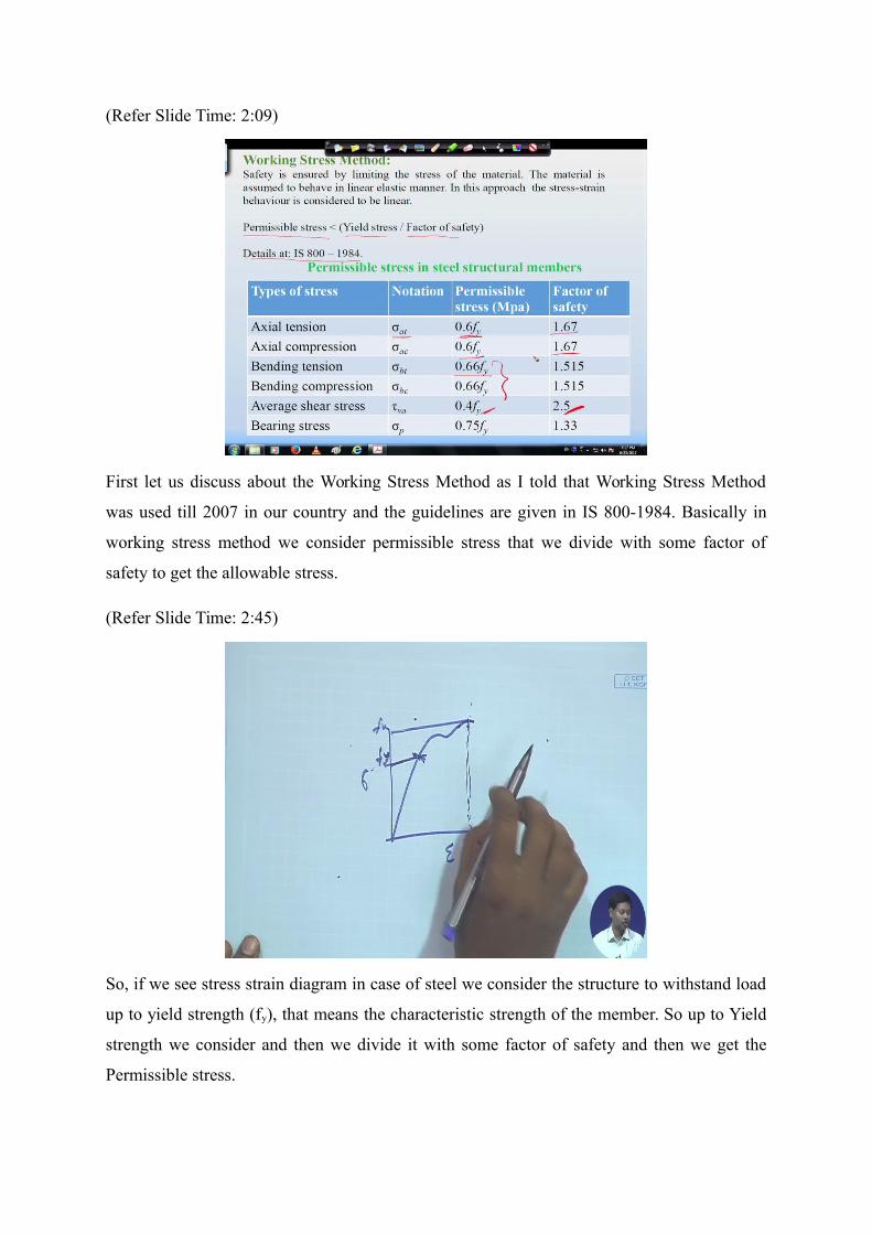
First let us discuss about the Working Stress Method as I told that Working Stress Method
was used till 2007 in our country and the guidelines are given in IS 800-1984. Basically in
working stress method we consider permissible stress that we divide with some factor of
safety to get the allowable stress.
(Refer Slide Time: 2:45)
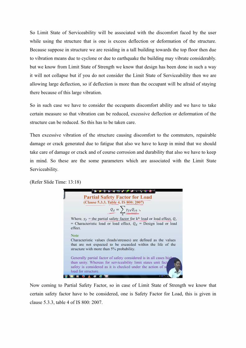
So, if we see stress strain diagram in case of steel we consider the structure to withstand load
up to yield strength (fy), that means the characteristic strength of the member. So up to Yield
strength we consider and then we divide it with some factor of safety and then we get the
Permissible stress.

If you see here I have written that Permissible stress is should be less than yield stress by
some factor of safety. So here, we assume the material to behave in linear elastic manner and
stress-strain diagram stress-strain behavior is also considered linear. That means we are not
considering beyond the yield stress though the member can take certain load after reaching
the yield stress.
The factor of safety in different case has been reported in IS 800-1984 the earlier code
Types of stress Notation Permissible stress (Mpa) Factor of safety
Axial tension σat 0.6fy 1.67
Axial compression σac 0.6fy 1.67
Bending tension σbt 0.66fy 1.515
Bending compression σbc 0.66fy 1.515
Average shear stress τva 0.4fy 2.5
Bearing stress σp 0.75fy 1.33
So, this is how the working stress method was used earlier but in this case there are certain
disadvantages or certain drawbacks were there. We do not consider load factor that means we
design based on service load but from the probabilistic point of view, we have to consider
that sometimes it may exceed that load we are considering
Therefore, in that case the structure may fail, so we cannot rely on this Working Stress
Method always. Another thing is that sometimes this Working Stress Method become very
conservative because we are taking upto the linear behavior of the stress-strain diagram, that
means we are considering up to the yield stress, but after yield stress the member can take
certain amount of load with certain deformation. Therefore, the nonlinear part, the inelastic
part we are not going to consider which is not correct. Therefore, if we consider that in our
design, then the construction cost or the size design member will become less and it will be
economic. And also we have to understand that the member we will design in such a way that
it should not be conservative, it should be economic and of course 100 percent safety has to
be considered. We will not compromise with any safety but at the same time we would try to
make it economic. So that is possible if we go Limit State Method what I am coming later.

(Refer Slide Time: 6:37)
Than another method which we considered earlier was Ultimate Strength Method. It is
basically a plastic design method, in this case the Limit State is attained when the members
reach plastic moment. That means in this case we go up to say fu, so up to this we consider
and then we design and of course, we also multiply some load factor factor with the working
load to get the Ultimate Load.
In this method, we do not consider the serviceability condition that means whether the
occupant feel discomfort or not, whether excessive deflection is coming or not that we do not
bother. So from the users point of view it is not advisable, so this method also became
nowadays obsolete.
Nowadays we prefer Limit State Method the structure is designed in such a way that it can
safely withstand all kind of loads that may act under consideration in its entire design life. So
that we have to consider the science of reliability based design with the objective of
providing a rational solution to the problem of adequate safety, that means we are not
compromising with the safety and uncertainty is reflected in loading and material strength. So
what we do here, we consider up to ultimate strength and we make use of some factor of
safety to get the permissible strength or the member.
So here we use some sort of factor of safety to ensure the uncertainty factor also we use the
load factor as we are not sure that what will be the actual load in the site. We try to find out
the maximum means worst possible combination and we multiply with some factor which
was obtained from reliability based method and then we try to design with that factored load

this is Limit State Method but this is Limit State of strength another is Limit State of
Serviceability that also we have to consider.
(Refer Slide Time: 9:43)
So in case of Limit State of Strength we have to consider the stability with Stability against
Overturning and Sway Stability that we have to keep in mind also we have to keep in mind
the Fatigue and Plastic Collapse. Therefore, Limit State of Strength depends on this few
aspects.
(Refer Slide Time: 10:23)
So in IS 800: 2007 the Limit State of Strength includes this few things which we have to keep
in mind like Loss of equilibrium of the structure as a whole or in part, loss of stability of the

structure, then failure due to excess deformation or rupture, fracture due to fatigue and brittle
fracture. So, these are associated with the failure which we have to keep in mind and we have
to design under the worst possible combination.
(Refer Slide Time: 11:07)
So as I told that one is Limit State of Strength, another is Limit State Serviceability. So Limit
State of Serviceability when we check Deflection limit, then Vibration limit, Durability
consideration and also Fire resistance. So these are few aspects from Limit State
Serviceability point of view, so we have to take care we have to keep in mind this limit and
we have to design the structural member keeping all these limits in our mind.
(Refer Slide Time: 11:42)
So Limit State of Serviceability will be associated with the discomfort faced by the user
while using the structure that is one is excess deflection or deformation of the structure.
Because suppose in structure we are residing in a tall building towards the top floor then due
to vibration means due to cyclone or due to earthquake the building may vibrate considerably.
but we know from Limit State of Strength we know that design has been done in such a way
it will not collapse but if you do not consider the Limit State of Serviceability then we are
allowing large deflection, so if deflection is more than the occupant will be afraid of staying
there because of this large vibration.
So in such case we have to consider the occupants discomfort ability and we have to take
certain measure so that vibration can be reduced, excessive deflection or deformation of the
structure can be reduced. So this has to be taken care.
Then excessive vibration of the structure causing discomfort to the commuters, repairable
damage or crack generated due to fatigue that also we have to keep in mind that we should
take care of damage or crack and of course corrosion and durability that also we have to keep
in mind. So these are the some parameters which are associated with the Limit State
Serviceability.
(Refer Slide Time: 13:18)
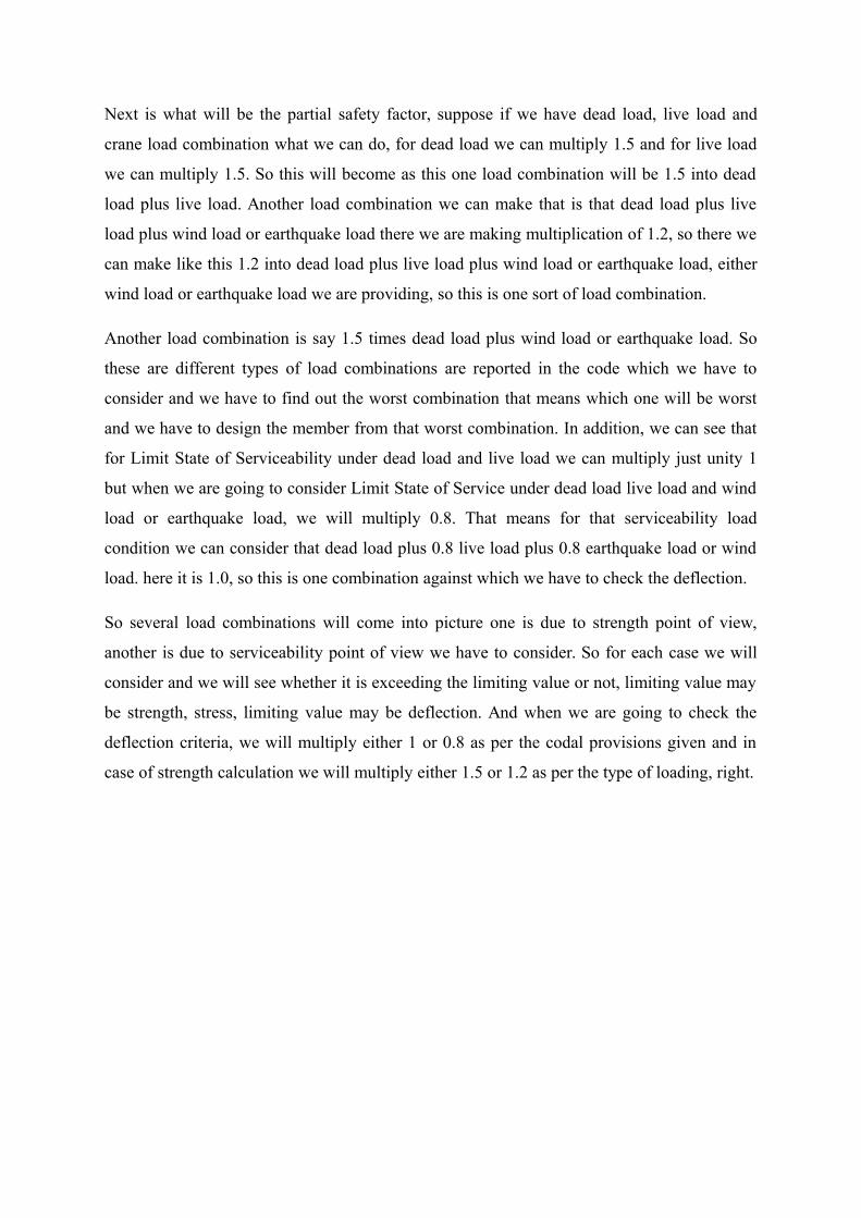
Now coming to Partial Safety Factor, so in case of Limit State of Strength we know that
certain safety factor have to be considered, one is Safety Factor for Load, this is given in
clause 5.3.3, table 4 of IS 800: 2007.

Where, Qck is the characteristic load or load effect and Qd the design load or load effect and
gamma is partial safety factor for k-th load or load effect. So this f is going to vary from time
to time depending on the type of loading, right.
(Refer Slide Time: 14:34)
So in table 4 of IS 800: 2007 this partial safety factors are given.
(Refer Slide Time: 15:23)
Next is what will be the partial safety factor, suppose if we have dead load, live load and
crane load combination what we can do, for dead load we can multiply 1.5 and for live load
we can multiply 1.5. So this will become as this one load combination will be 1.5 into dead
load plus live load. Another load combination we can make that is that dead load plus live
load plus wind load or earthquake load there we are making multiplication of 1.2, so there we
can make like this 1.2 into dead load plus live load plus wind load or earthquake load, either
wind load or earthquake load we are providing, so this is one sort of load combination.
Another load combination is say 1.5 times dead load plus wind load or earthquake load. So
these are different types of load combinations are reported in the code which we have to
consider and we have to find out the worst combination that means which one will be worst
and we have to design the member from that worst combination. In addition, we can see that
for Limit State of Serviceability under dead load and live load we can multiply just unity 1
but when we are going to consider Limit State of Service under dead load live load and wind
load or earthquake load, we will multiply 0.8. That means for that serviceability load
condition we can consider that dead load plus 0.8 live load plus 0.8 earthquake load or wind
load. here it is 1.0, so this is one combination against which we have to check the deflection.
So several load combinations will come into picture one is due to strength point of view,
another is due to serviceability point of view we have to consider. So for each case we will
consider and we will see whether it is exceeding the limiting value or not, limiting value may
be strength, stress, limiting value may be deflection. And when we are going to check the
deflection criteria, we will multiply either 1 or 0.8 as per the codal provisions given and in
case of strength calculation we will multiply either 1.5 or 1.2 as per the type of loading, right.

(Refer Slide Time: 17:56)
Where, = Partial safety factor for material as given in Table 5.
= Ultimate strength of the material, = Design strength of the material.
(Refer Slide Time: 18:37)
So if you see the table 5, we can see the different Partial Safety Factor has been considered
for different type of material condition, like in case of yielding resistance governed by

yielding so gamma m0 is one safety factor which is considered as 1.10, whereas resistance of
member to buckling that also as 1.10 that also gamma m0 and resistance governed by
ultimate stress that we are making 1.25 partial safety factor that means we are dividing the
partial safety factor with the ultimate strength to get the design strength.
And for connection for bolt, friction type bolt gamma mf we use 1.25 for shop fabrication
also 1.25 for field fabrication, whereas for bearing type also this is 1.25, 1.25, in case of rivet
also we provide 1.25 and in case of weld we provide in shop fabrication 1.25 and for field
fabrication we increase that the factor of safety upto 1.5, so this is how the factor safety has
been decided and reported in the code which we have to consider and we have to divide with
these factor of safety with the ultimate strength of the material to get the design strength of
the material.

(Refer Slide Time: 20:09)
Another is the serviceability criteria, for serviceability criteria deflection limits has been
defined in, table 6 of IS 800: 2007. Different limits have been provided, say for in case of
industrial building, I am just showing few of them one is vertical deflection another is lateral
deflection, and again design load will be due to live load/wind load, due to live load only. So
different type of design load will be considered and =different type of members have different
limiting condition. Therefore, for different type of supporting condition and different type of
members the limiting deflection has been given in the table 6.
(Refer Slide Time: 22:02)
So this is the continuation of the table 6 for other buildings, one is industrial building and
another one is other buildings we have given.
(Refer Slide Time: 22:10)
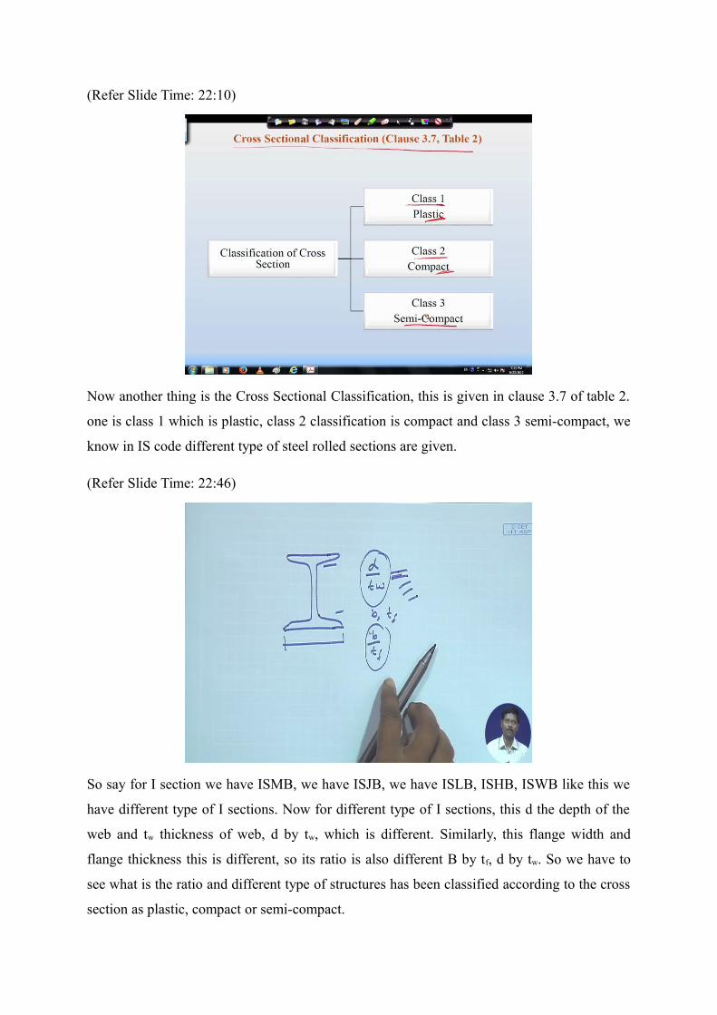
Now another thing is the Cross Sectional Classification, this is given in clause 3.7 of table 2.
one is class 1 which is plastic, class 2 classification is compact and class 3 semi-compact, we
know in IS code different type of steel rolled sections are given.
(Refer Slide Time: 22:46)
So say for I section we have ISMB, we have ISJB, we have ISLB, ISHB, ISWB like this we
have different type of I sections. Now for different type of I sections, this d the depth of the
web and tw thickness of web, d by tw, which is different. Similarly, this flange width and
flange thickness this is different, so its ratio is also different B by tf, d by tw. So we have to
see what is the ratio and different type of structures has been classified according to the cross
section as plastic, compact or semi-compact.

So for a particular type of member, we have to decide means particular type of cross section
we have to decide means we have to see whether this cross section is under plastic, semi-
compact or compact and accordingly design criteria will be followed. So these things we
have to keep in mind.
(Refer Slide Time: 24:00)
Then coming to Load and Load Combinations, load is important because under the particular
load we have to design the member and that load may be dead load means due to self-weight,
may be live load, may be wind load or systemic load or may be other type of load like
accidental load or snow load, hydrostatic load, different type of loads are there. So then we
have to know what are the codal provisions, how to calculate the load on a particular member.
Then we have to go for the load combination with certain factor of safety that we have seen.
So here if we see, the different type of loads are given in IS:875 in part 1 to part 5, IS:875
part 1 to part 5, various load and load combinations have been given and now in part 1 the
dead loads of the structures have been given. Mass density of different kind of material like
brick, plaster, concrete are given in detail in IS:875 part 1.
So the dead load calculation or the self-weight of the structure if we want to calculate, then
we have to go through the IS:875 part 1 and then we have to see what is the total dead load or
self-weight coming into this structure.
Next is the live load or imposed load. Live load or imposed load is given in IS:875 part 2, in
part 2 different type of live loads are given like in case of residential building what will be the

live load, in case of industrial building what will be the live load, in case of office building
what will be the live load that has been specified. Again in case of residential building in
balcony, in kitchen, in bedroom what will be the live load, the different live loads are
specified, so that has to be taken care from that code.
Another is the crane load crane load also can be found from this part 2, then coming to wind
load wind load is given in IS:875 (Part-3), so wind load I will be coming details after this
slide. Then snow load in the area, where snow is a factor there we have to consider the snow
load and that has been given in part-4, and in part-5 the temperature load, hydrostatic load,
soil pressure, fatigue, accidental impact, explosions etc and different type of load
combinations are given in part-5. So part-5 consist of temperature load, hydrostatic load, soil
pressure, fatigue, accidental load, impact, explosions etc and different type of load
combinations means dead load plus live load, dead load plus wind load, dead load plus live
load plus wind load, like this different load combinations are recommended in part-5.
And earthquake load you can find out in IS:1893-2002, in case of earthquake load we know
in our country we had 5 zones, now we have 4 number of zones, zone 1 and zone 2 is clubbed
to zone 2, so zone 2, zone 3, zone 4 and zone 5 and zone 5 is the most systematically active
zone. So for different zone what is the systemic coefficient for calculating the load that has
been given in the code in IS:1893-2002, so detail calculation of load due to earthquake can be
found in this code and according to that we have to calculate the load coming to the particular
structure and then we have to apply that load to the structure to design the structural member.
Then erection load is given in IS: 800-2007 in Clause 3.3, the details are there and also other
secondary effects such as temperature change, differential settlement, eccentric connections
those things also has to be taken care in the load and load combinations because due to
differential settlement and temperature, extra load will come into picture, so that has to be
also taken care in the design calculation.

(Refer Slide Time: 29:21)
Now in clause 5.3.1 if we see the structural system has been classified in three groups, one is
the permanent action, permanent action means the load which are permanent in nature these
are basically self-weight of the structure which we call generally dead load, so these are
permanent action. Another is variable action, variable action is basically imposed load and
wind or earthquake load are not permanent these are temporary and variable so these are
under variable actions. Another is accidental actions, action due to accidental load like
explosion or due to sudden impact such type of accidental actions happen, so that has to also
be taken care.
And we have told that while designing the steel structure the load combination have to be
considered with partial safety factor. Partial safety factor I have already discussed that is dead
load plus imposed load, here we will multiply with 1.5 and dead load plus imposed load plus
wind or seismic load that is 1.2, we will multiply dead load plus wind load here also we
multiply 1.5, like this dead load plus erection load, so these are some load combinations
which we have to take into consideration for the design of the member.

(Refer Slide Time: 30:51)
Now very briefly I will go through the wind load calculation because in case of steel structure
wind load is a factor for designing the steel members because the steel structures are light in
weight so it is vulnerable to cyclone and wind. Therefore we need to calculate what are the
wind load coming in to the steel structures and accordingly we have to find out the design
criteria means we have to find out the load coming on a particular member and then
accordingly we have to design, not only we will design we will check the limiting deflection
because serviceability criteria has to be also maintained.
So what is the deflection coming due to wind because steel are ductile in nature so lot of
deflection will come in comparison to concrete structure therefore we have to check the
serviceability criteria as well, right. So thinking that I am going to give a brief review on the
wind calculation and I told that wind calculation is given in the code IS 875 (Part 3). You will
get the detail of wind calculation and here the design wind speed Vz (m/s) is calculated
where Vb is a basic wind speed and these basic wind speed are divided in our country in six
zone, ok in six different zone it has been given like in zone one the basic wind is 55 meter per
second this is the highest speed, then in zone two it is 50, zone three it is 47, zone four 44,
zone five 39 and zone six is 33 m/s
In IS 875, figure 1, the basic wind speed for different zone has been given also at the end of
the IS code in a tabular form it is given for different city what will be the basic wind speed.

Next is the probability factor k1, k2, k3, k1 is the probability factor or risk coefficient this is
given in table 1, I am not going into details if you look through the code you will be able to
understand all the details have been given. Then, k2 depends on the terrain, height and
structure size, so that factor is given as k2 and in table 2 that is given, you will see that
according to height the k2 factor is going to increase like this it is going to increase that
means the wind speed will go on increasing with the increase of height. Another is k3, k3 is
the topography factor means in what type of topography structure is going to be constructed
whether it is valley or anything else or plain land depending on that what is the slope
depending on that the k3 factor will be calculated these details you can find out in Clause
5.3.3.
(Refer Slide Time: 34:51)
Now Wind Pressure, Wind Pressure we can find out from this formula
The wind pressure at any height of a structure depends on following.
Velocity and density of the air Height above ground level Shape and aspect ratio of the building Topography of the surrounding ground surface Angle of wind attack Solidity ratio or openings in the structure

(Refer Slide Time: 37:02)
Once we get the design wind pressure we can find out the wind force
Where,Cf =Force coefficient of the building Ae =Effective frontal area pz =design wind pressure
(Refer Slide Time: 38:23)
Another thing is we have to consider that wind force on roof and walls as an individual
means if there is a roof suppose we have a building like this and it has a roof so there we can

find out what is the wind pressure is coming from externally and what is the internal wind
pressure is coming depending on that we have to find out the force and this force can be
calculated from this formula
[cl. 6.2.1 of IS 875 part-3]
Where, Cpe =External pressure coefficient (cl. 6.2.2 of IS 875 part-3)
Cpi=Internal pressure coefficient (cl. 6.2.3 of IS 875 part-3)
A = Surface area of structural element
So if we can find out this value the coefficient external pressure coefficient and internal
pressure coefficient and the surface area then we can find out the wind force on roof or wall
as an individual, right so this is how we can calculate the wind force.
So this is all about today’s lecture and we have seen in todays lecture that why Limit State
Method is important and why it is more accurate, more practical compared to other two
methods that is Ultimate Strength Method and Working Stress Method. Why we have moved
to Limit State Method that is understandable now and tomorrow onwards when we will be
going for design of members or connections, individual members or connections will follow
this criteria that means Limit State Method design criteria, where the load factor and the
partial safety factor for the material will be considered and what will be the load combination
for which we have to design that will be considered and we have seen the what is the ultimate
strength of the member, what is the yield strength of the member for the steel that according
to the different weight we can find out and we can make use of those parameters for design of
the elemental means element or member,.So with this I will have to conclude todays lecture,
thank you.