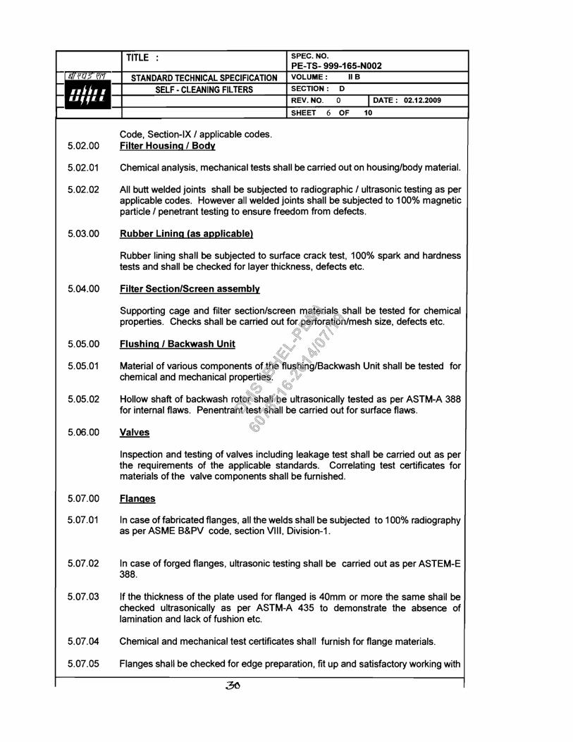
cover sheet mouda - bharat heavy electricals ltd. (i.e. between inlet and outlet connection) at...
TRANSCRIPT


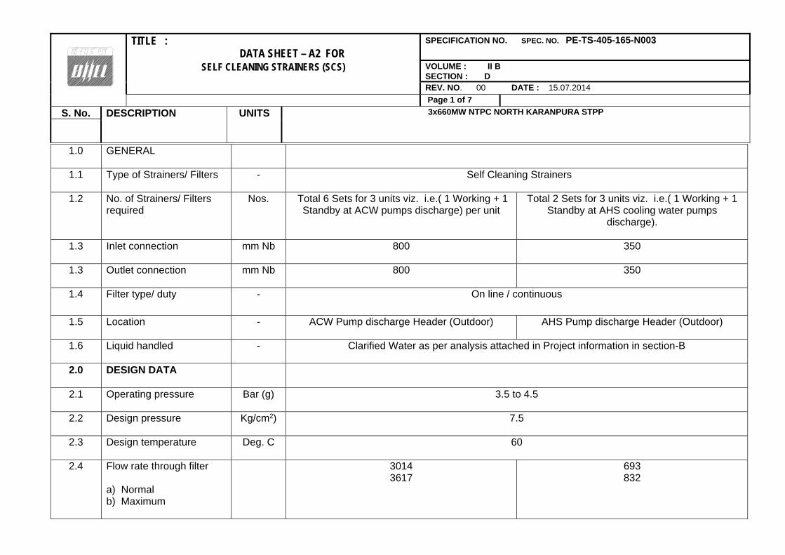
TITLE : DATA SHEET – A2 FOR
SPECIFICATION NO. SPEC. NO. PE-TS-405-165-N003
SELF CLEANING STRAINERS (SCS) VOLUME : II B SECTION : D
REV. NO. 00 DATE : 15.07.2014
Page 1 of 7 S. No. DESCRIPTION UNITS 3x660MW NTPC NORTH KARANPURA STPP
1.0 GENERAL
1.1 Type of Strainers/ Filters
- Self Cleaning Strainers
1.2 No. of Strainers/ Filters required
Nos. Total 6 Sets for 3 units viz. i.e.( 1 Working + 1 Standby at ACW pumps discharge) per unit
Total 2 Sets for 3 units viz. i.e.( 1 Working + 1 Standby at AHS cooling water pumps
discharge).
1.3 Inlet connection
mm Nb 800 350
1.3 Outlet connection
mm Nb 800 350
1.4 Filter type/ duty
- On line / continuous
1.5 Location
- ACW Pump discharge Header (Outdoor) AHS Pump discharge Header (Outdoor)
1.6 Liquid handled
- Clarified Water as per analysis attached in Project information in section-B
2.0 DESIGN DATA
2.1 Operating pressure
Bar (g) 3.5 to 4.5
2.2 Design pressure
Kg/cm2) 7.5
2.3 Design temperature
Deg. C 60
2.4 Flow rate through filter a) Normal b) Maximum
3014 3617
693 832

TITLE : DATA SHEET – A2 FOR
SPECIFICATION NO. SPEC. NO. PE-TS-405-165-N003
SELF CLEANING STRAINERS (SCS) VOLUME : II B SECTION : D
REV. NO. 00 DATE : 15.07.2014
Page 2 of 7 S. No. DESCRIPTION UNITS 3x660MW NTPC NORTH KARANPURA STPP
2.5 Design differential pressure for filter section/ screen
Bar (g) 1.5 (Min.)
2.6 Type of suspended matter likely to enter the filter
- Typical debris encountered in closed circuit CW system with Cooling Tower
2.7 Differential pressure measuring system set pressure For initiating flushing/
backwashing For alarm/
annunciation
mbar
mbar
110
160
2.8 Filter section/ screen perforation size
mm 2 mm (Max)
2.9 Free flow area in the screen basket
- At least 120 % of pipe inlet area
3.0 GUARANTEED PERFORMANCE REQUIREMENT
3.1 Pressure drop across the filter (i.e. between inlet and outlet connection) at normal flow
-
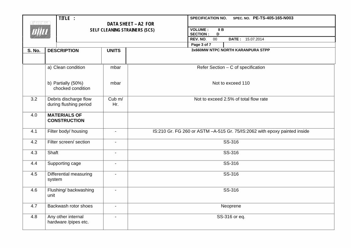
TITLE : DATA SHEET – A2 FOR
SPECIFICATION NO. SPEC. NO. PE-TS-405-165-N003
SELF CLEANING STRAINERS (SCS) VOLUME : II B SECTION : D
REV. NO. 00 DATE : 15.07.2014
Page 3 of 7 S. No. DESCRIPTION UNITS 3x660MW NTPC NORTH KARANPURA STPP
a) Clean condition b) Partially (50%)
chocked condition
mbar
mbar
Refer Section – C of specification
Not to exceed 110
3.2 Debris discharge flow during flushing period
Cub m/ Hr.
Not to exceed 2.5% of total flow rate
4.0
MATERIALS OF CONSTRUCTION
4.1 Filter body/ housing
- IS:210 Gr. FG 260 or ASTM –A-515 Gr. 75/IS:2062 with epoxy painted inside
4.2 Filter screen/ section
- SS-316
4.3 Shaft
- SS-316
4.4 Supporting cage
- SS-316
4.5 Differential measuring system
- SS-316
4.6 Flushing/ backwashing unit
- SS-316
4.7 Backwash rotor shoes
- Neoprene
4.8 Any other internal hardware /pipes etc.
- SS-316 or eq.

TITLE : DATA SHEET – A2 FOR
SPECIFICATION NO. SPEC. NO. PE-TS-405-165-N003
SELF CLEANING STRAINERS (SCS) VOLUME : II B SECTION : D
REV. NO. 00 DATE : 15.07.2014
Page 4 of 7 S. No. DESCRIPTION UNITS 3x660MW NTPC NORTH KARANPURA STPP
4.9
Valves -
4.9.1 Gate valves (65Nb and above)/Check Valves (all sizes)
a) Body & Bonnet - ASTM A 216 Gr. WCB/ASTM A105
b) Disc for Check Valve - ASTM A 216 Gr. WCB/ASTM A105
c) Trim - ASTM A 182 Gr. F6 or equivalent
4.9.2 Globe Valves 50 Nb & Below
Body, Bonnet & trim ASTM A-105
Stem 13% Chrome steel ASTM-A-182-Gr. F6a
4.9.3 C) Ball valves i) Body ii) Ball iii) Stem
SA 351 CF8M
SA 351 CF8M
SS 316
4.10
Piping - By Bidder
Material a) upto 150 Nb Carbon steel ERW, IS:1239 (Heavy Grade)
a) 200 Nb and above carbon steel (IS:2062), Rolled & Welded confirming to IS:3589

TITLE : DATA SHEET – A2 FOR
SPECIFICATION NO. SPEC. NO. PE-TS-405-165-N003
SELF CLEANING STRAINERS (SCS) VOLUME : II B SECTION : D
REV. NO. 00 DATE : 15.07.2014
Page 5 of 7 S. No. DESCRIPTION UNITS 3x660MW NTPC NORTH KARANPURA STPP
5.0 COUNTER FLANGES
In Bidder’s Scope
5.1 Material Flanges IS 2062, Gr. B, epoxy painted
5.2 Drilling Standard
- BS 4504 or equivalent
6.0 Connecting pipe size (OD & Thk)
mm 813 X 8 355.6 X 6
7.0 PAINTING
7.1 External Surface
-
a) Surface preparation
- Power tool cleaning/Shot blasting/ abrasive blasting
b) Primer
Two coats of Zinc chrome primer (Alkyd base) by brush/spray to IS 104 OR Two coats of Red oxide Zinc Phosphate based primer (alkyd base)to IS 12744 with min. DFT per coat of 25 microns
Intermediate One coat of Synthetic enamel (long oil alkyd) to IS 2932 with min. DFT of 30 microns c) Final paint Two coats of Synthetic enamel (long oil alkyd) to IS 2932 with min. DFT of 35 microns to achieve
total min DFT of 150 microns. 7.2 Internal Surface
a) Surface preparation
SA 2.5 of Swedish Specification SIS 05.5900.197
b) Primer
One coat of epoxy resin based primer
c) Final paint Applicable no. Of coats of coal tar epoxy paint to achieve total DFT of 200 to 250 microns 8.0 SHOP TEST
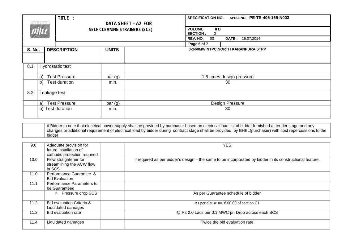
TITLE : DATA SHEET – A2 FOR
SPECIFICATION NO. SPEC. NO. PE-TS-405-165-N003
SELF CLEANING STRAINERS (SCS) VOLUME : II B SECTION : D
REV. NO. 00 DATE : 15.07.2014
Page 6 of 7 S. No. DESCRIPTION UNITS 3x660MW NTPC NORTH KARANPURA STPP
8.1 Hydrostatic test
a) Test Pressure bar (g) 1.5 times design pressure b) Test duration
min. 30
8.2 Leakage test
a) Test Pressure bar (g) Design Pressure b) Test duration
min. 30
# Bidder to note that electrical power supply shall be provided by purchaser based on electrical load list of bidder furnished at tender stage and any
changes or additional requirement of electrical load by bidder during contract stage shall be provided by BHEL(purchaser) with cost repercussions to the bidder
9.0 Adequate provision for
future installation of cathodic protection required
YES
10.0 Flow straightener for streamlining the ACW flow in SCS
If required as per bidder’s design – the same to be incorporated by bidder in its constructional feature.
11.0 Performance Guarantee & Bid Evaluation
11.1 Performance Parameters to be Guaranteed
Pressure drop SCS As per Guarantee schedule of bidder
11.2 Bid evaluation Criteria & Liquidated damages
As per clause no. 8.00.00 of section C1
11.3 Bid evaluation rate @ Rs 2.0 Lacs per 0.1 MWC pr. Drop across each SCS
11.4 Liquidated damages Twice the bid evaluation rate

TITLE : DATA SHEET – A2 FOR
SPECIFICATION NO. SPEC. NO. PE-TS-405-165-N003
SELF CLEANING STRAINERS (SCS) VOLUME : II B SECTION : D
REV. NO. 00 DATE : 15.07.2014
Page 7 of 7 S. No. DESCRIPTION UNITS 3x660MW NTPC NORTH KARANPURA STPP
12.0 Whether automatic flushing/ back- washing operation effected by the following :
i. Differential pressure
ii. Adjustable timer iii. Push button
YES
YES YES
13.0 Whether provision for manual flushing / backwashing operation is made in the event of control system failure.
YES
14.0
Whether built in flushing arrangement complete with flushing pump, valves, and associated piping, is provided.
YES (if required)
15.0 Mandatory Spare to be supplied under this specification
NIL

ANNEX TO DATASHEET-A
PIPE SIZE TABLE (REFER CL. N. 6.2, SECTION C1, Vol.IIB)


TITLE : TECHNICAL SPECIFICATION SPEC. NO. PE-TS-405-165-N003
FOR VOLUME : IIB
SELF CLEANING STRAINERS (SCS) SECTION : D
REV. NO. 0 DATE :15.07.2014
SHEET 1of 1
SECTION D2
STANDARD TECHNICAL SPECIFICATION FOR
ELECTRICAL SYSTEMS

TITLE : GENERAL TECHNICAL REQUIREMENTs
FOR
LV MOTORS
SPECIFICATION NO. PE-SS-999-506-E101 VOLUME NO. : II-B SECTION : D REV NO. : 00 DATE : 28.01.10 SHEET : 1 OF 1
GENERAL TECHNICAL REQUIREMENTS
FOR
LV MOTORS
SPECIFICATION NO.: PE-SS-999-506-E101 Rev 00

TITLE : GENERAL TECHNICAL REQUIREMENTs
FOR
LV MOTORS
SPECIFICATION NO. PE-SS-999-506-E101 VOLUME NO. : II-B SECTION : D REV NO. : 00 DATE : 28.01.10 SHEET : 1 OF 4
1.0 INTENT OF SPECIFIATION
The specification covers the design, materials, constructional features, manufacture, inspection and testing at manufacturer’s work, and packing of Low voltage (LV) squirrel cage induction motors along with all accessories for driving auxiliaries in thermal power station.
Motors having a voltage rating of below 1000V are referred to as low voltage (LV) motors. 2.0 CODES AND STANDARDS Motors shall fully comply with latest edition, including all amendments and revision, of following
codes and standards: IS:325 Three phase Induction motors IS : 900 Code of practice for installation and maintenance of induction motors IS: 996 Single phase small AC and universal motors IS: 4722 Rotating Electrical machines IS: 4691 Degree of Protection provided by enclosures for rotating electrical machines IS: 4728 Terminal marking and direction of rotation rotating electrical machines IS: 1231 Dimensions of three phase foot mounted induction motors IS: 8789 Values of performance characteristics for three phase induction motors IS: 13555 Guide for selection and application of 3-phase A.C. induction motors for
different types of driven equipment IS: 2148 Flame proof enclosures for electrical appliance IS: 5571 Guide for selection of electrical equipment for hazardous areas IS: 12824 Type of duty and classes of rating assigned IS: 12802 Temperature rise measurement ofr rotating electrical machnines IS: 12065 Permissible limits of noise level for rotating electrical machines IS: 12075 Mechnical vibration of rotatinf electrical machines In case of imported motors, motors as per IEC-34 shall also be acceptable.
3.0 DESIGN REQUIREMENTS 3.1 Motors and accessories shall be designed to operate satisfactorily under conditions specified in data
sheet-A and Project Information, including voltage & frequency variation of supply system as defined in Data sheet-A
3.2 Motors shall be continuously rated at the design ambient temperature specified in Data Sheet-A and
other site conditions specified under Project Information Motor ratings shall have at least a 15% margin over the continuous maximum demand of the driven equipment, under entire operating range including voltage & frequency variation specified above.
3.3 Starting Requirements 3.3.1 Motor characteristics such as speed, starting torque, break away torque and starting time shall be
properly co-ordinated with the requirements of driven equipment. The accelerating torque at any speed with the minimum starting voltage shall be at least 10% higher than that of the driven equipment.
3.3.2 Motors shall be capable of starting and accelerating the load with direct on line starting without
exceeding acceptable winding temperature.

TITLE : GENERAL TECHNICAL REQUIREMENTs
FOR
LV MOTORS
SPECIFICATION NO. PE-SS-999-506-E101 VOLUME NO. : II-B SECTION : D REV NO. : 00 DATE : 28.01.10 SHEET : 2 OF 4
The limiting value of voltage at rated frequency under which a motor will successfully start and
accelerate to rated speed with load shall be taken to be a constant value as per Data Sheet - A during the starting period of motors.
3.3.3 The following frequency of starts shall apply
i) Two starts in succession with the motor being initially at a temperature not exceeding the rated load temperature.
ii) Three equally spread starts in an hour the motor being initially at a temperature not exceeding
the rated load operating temperature. (not to be repeated in the second successive hour)
iii) Motors for coal conveyor and coal crusher application shall be suitable fro three consecutive hot starts followed by one hour interval with maximum twenty starts per day and shall be sutable fro mimimum 20,000 starts during the life time of the motor
3.4 Running Requirements 3.4.1 Motors shall run satisfactorily at a supply voltage of 75% of rated voltage for 5 minutes with full load
without injurious heating to the motor. 3.4.2 Motor shall not stall due to voltage dip in the system causing momentary drop in voltage upto 70% of
the rated voltage for duration of 2 secs. 3.5 Stress During bus Transfer 3.5.1 Motors shall withstand the voltage, heavy inrush transient current, mechnical and torque stress
developed due to the application of 150% of the rated voltage for at least 1 sec. caused due to vector difference between the motor residual voltage and the incoming supply voltage during occasional auto bus transfer.
3.5.2 Motor and driven equipment shafts shall be adequately sized to satisfactorily withstand transient
torque under above condition. 3.6 Maximum noise level measured at distance of 1.0 metres from the outline of motor shall not exceed
the values specified in IS 12065. 3.7 The max. vibration velocity or double amplitude of motors vibration as measured at motor bearings
shall be within the limits specified in IS: 12075. 4.0 CONSTRUCTIONAL FEATURES 4.1 Indoor motors shall conform to degree of protection IP: 54 as per IS: 4691. Outdoor or semi-indoor
motors shall conform to degree of protection IP: 55 as per IS: 4691and shall be of weather-proof construction. Outdoor motors shall be installed under a suitable canopy
4.2 Motors upto 160KW shall have Totally Enclosed Fan Cooled (TEFC) enclosures, the method of
cooling conforming to IC-0141 or IC-0151 of IS: 6362.
Motors rated above 160 KW shall be Closed Air Circuit Air (CACA) cooled 4.3 Motors shall be designed with cooling fans suitable for both directions of rotation.

TITLE : GENERAL TECHNICAL REQUIREMENTs
FOR
LV MOTORS
SPECIFICATION NO. PE-SS-999-506-E101 VOLUME NO. : II-B SECTION : D REV NO. : 00 DATE : 28.01.10 SHEET : 3 OF 4
4.4. Motors shall not be provided with any electric or pneumatic operated external fan for cooling the
motors. 4.5 Frames shall be designed to avoid collection of moisture and all enclosures shall be provided with
facility for drainage at the lowest point. 4.6 In case Class ‘F’ insulation is provided for LV motors, temperature rise shall be limited to the limits
applicable to Class ‘B’ insulation. In case of continuous operation at extreme voltage limits the temperature limits specified in table-1 of IS:325 shall not exceed by more than 10C.
4.7 Terminals and Terminal Boxes 4.7.1 Terminals, terminal leads, terminal boxes, windings tails and associated equipment shall be suitable
for connection to a supply system having a short circuit level, specified in the Data Sheet-A. Unless otherwise statedin Data Sheet-A, motors of rating 110 kW and above will be controlled by
circuit breaker and below 110 kW by switch fuse-contactor. The terminal box of motors shall be designed for the fault current mentioned in data sheet “A”.
4.7.2 Unless otherwise specified or approved, phase terminal boxes of horizontal motors shall be positioned
on the left hand side of the motor when viewed from the non-driving end. 4.7.3 Connections shall be such that when the supply leads R, Y & B are connected to motor terminals A B
& C or U, V & W respectively, motor shall rotate in an anticlockwise direction when viewed from the non-driving end. Where such motors require clockwise rotation, the supply leads R, Y, B will be connected to motor terminals A, C, B or V W & V respectively.
4.7.4 Permanently attached diagram and instruction plate made preferably of stainless steel shall be
mounted inside terminal box cover giving the connection diagram for the desired direction of rotation and reverse rotation.
4.7.5 Motor terminals and terminal leads shall be fully insulated with no bar live parts. Adequate space
shall be available inside the terminal box so that no difficulty is encountered for terminating the cable specified in Data Sheet-A.
4.7.6 Degree of protection for terminal boxes shall be IP 55 as per IS 4691. 4.7.7 Separate terminal boxes shall be provided for space heaters.. If this is not possible in case of LV
motors, the space heater terminals shall be adequately segregated from the main terminals in the main terminal box. Detachable gland plates with double compression brass glands shall be provided in terminal boxes.
4.7.8. Phase terminal boxes shall be suitable for 360 degree of rotation in steps of 90 degree for LV motors. 4.7.9 Cable glands and cable lugs as per cable sizes specified in Data Sheet-A shall be included. Cable lugs
shall be of tinned Copper, crimping type. 4.8 Two separate earthing terminals suitable for connecting G.I. or MS strip grounding conductor of size
given in Data Sheet-A shall be provided on opposite sides of motor frame. Each terminal box shall have a grounding terminal.
4.9 General
TITLE : GENERAL TECHNICAL REQUIREMENTs
FOR
LV MOTORS
SPECIFICATION NO. PE-SS-999-506-E101 VOLUME NO. : II-B SECTION : D REV NO. : 00 DATE : 28.01.10 SHEET : 4 OF 4
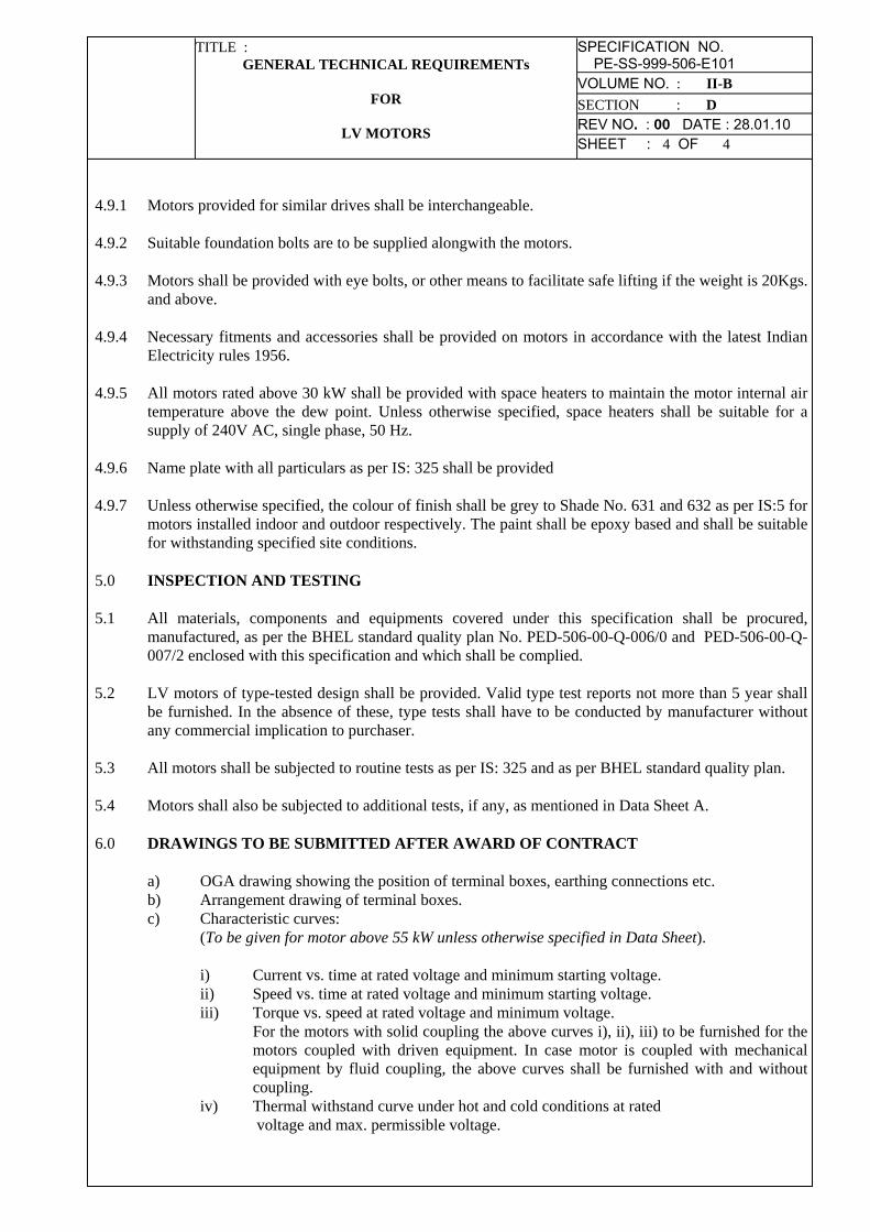
4.9.1 Motors provided for similar drives shall be interchangeable. 4.9.2 Suitable foundation bolts are to be supplied alongwith the motors. 4.9.3 Motors shall be provided with eye bolts, or other means to facilitate safe lifting if the weight is 20Kgs.
and above. 4.9.4 Necessary fitments and accessories shall be provided on motors in accordance with the latest Indian
Electricity rules 1956. 4.9.5 All motors rated above 30 kW shall be provided with space heaters to maintain the motor internal air
temperature above the dew point. Unless otherwise specified, space heaters shall be suitable for a supply of 240V AC, single phase, 50 Hz.
4.9.6 Name plate with all particulars as per IS: 325 shall be provided 4.9.7 Unless otherwise specified, the colour of finish shall be grey to Shade No. 631 and 632 as per IS:5 for
motors installed indoor and outdoor respectively. The paint shall be epoxy based and shall be suitable for withstanding specified site conditions.
5.0 INSPECTION AND TESTING 5.1 All materials, components and equipments covered under this specification shall be procured,
manufactured, as per the BHEL standard quality plan No. PED-506-00-Q-006/0 and PED-506-00-Q-007/2 enclosed with this specification and which shall be complied.
5.2 LV motors of type-tested design shall be provided. Valid type test reports not more than 5 year shall
be furnished. In the absence of these, type tests shall have to be conducted by manufacturer without any commercial implication to purchaser.
5.3 All motors shall be subjected to routine tests as per IS: 325 and as per BHEL standard quality plan. 5.4 Motors shall also be subjected to additional tests, if any, as mentioned in Data Sheet A. 6.0 DRAWINGS TO BE SUBMITTED AFTER AWARD OF CONTRACT a) OGA drawing showing the position of terminal boxes, earthing connections etc. b) Arrangement drawing of terminal boxes. c) Characteristic curves: (To be given for motor above 55 kW unless otherwise specified in Data Sheet). i) Current vs. time at rated voltage and minimum starting voltage. ii) Speed vs. time at rated voltage and minimum starting voltage.
iii) Torque vs. speed at rated voltage and minimum voltage. For the motors with solid coupling the above curves i), ii), iii) to be furnished for the motors coupled with driven equipment. In case motor is coupled with mechanical equipment by fluid coupling, the above curves shall be furnished with and without coupling.
iv) Thermal withstand curve under hot and cold conditions at rated voltage and max. permissible voltage.

CLAUSE NO.
QUALITY ASSURANCE
NORTH KARANPURA STPP (3 X 660 MW)
EPC PACKAGE
TECHNICAL SPECIFICATION SECTION-VI, PART-B
BID DOC NO.:CS-4410-001-2
SUB-SECTION-E-48 MOTOR
Page 1 of 2
MOTOR TESTS/CHECKS TEMS/COMPONENTS V
isua
l
Dim
ensi
onal
M
ake/
Type
/Rat
ing
/Gen
eral
P
hysi
cal I
nspe
ctio
n
Mec
h/C
hem
. Pro
perti
es
ND
T /D
P/M
PI/U
T
Met
allo
grap
hy
Elec
trica
l Cha
ract
eris
tics
Wel
ding
/Bra
zing
(WP
S/P
QR
)
Hea
t Tre
atm
ent
Plates for stator frame, end shield, spider etc.
Y Y Y Y Y Y
Shaft Y Y Y Y Y Y Y Magnetic Material Y Y Y Y Y Rotor Copper/Aluminium Y Y Y Y Y Y Stator copper Y Y Y Y Y Y SC Ring Y Y Y Y Y Y Y Y Insulating Material Y Y Y Y Tubes, for Cooler Y Y Y Y Y Y Sleeve Bearing Y Y Y Y Y Y Stator/Rotor, Exciter Coils Y Y Y Y Y Castings, stator frame, terminal box and bearing housing etc.
Y Y Y Y Y Y
Fabrication & machining of stator, rotor, terminal box
Y Y Y Y Y
Wound stator Y Y Y Y Wound Exciter Y Y Y Y Rotor complete Y Y Y Exciter, Stator, Rotor, Terminal Box assembly
Y Y Y
Accessories, RTD, BTD,CT, Space heater, antifriction bearing, gaskets etc.
Y Y Y
Complete Motor Y Y Y
Note: 1. This is an indicative list of tests/checks. The manufacture is to furnish a detailed Quality Plan indicating the practices & Procedure followed along with relevant supporting documents during QP finalization. However, No QP for LT motor upto 50KW. 2. Additional routine tests for Flame proof motors shall be applicable as per relevant standard 3. Makes of major bought out items for HT motors will be subject to NTPC approval. Y1 = for HT Motor / Machines only.

CLAUSE NO.
QUALITY ASSURANCE
NORTH KARANPURA STPP (3 X 660 MW)
EPC PACKAGE
TECHNICAL SPECIFICATION SECTION-VI, PART-B
BID DOC NO.:CS-4410-001-2
SUB-SECTION-E-48 MOTOR
Page 2 of 2
MOTOR
TESTS/CHECKS ITEMS/COMPONENTS M
agne
tic C
hara
cter
istic
s
Hyd
raul
ic/L
eak/
Pre
ssur
e Te
st
Ther
mal
Cha
ract
eris
tics
Run
out
Dyn
amic
Bal
anci
ng
Rou
tine
& Ac
cept
ance
tes
ts a
s pe
r IS
-325
/IS-4
722
/IS-
928
3/IS
21
48/IE
C60
034\
IEC
600
79-I
Vibr
atio
n
Ove
r spe
ed
Tan
delta
, sha
ft vo
ltage
&
pola
rizat
ion
inde
x te
st
Pain
t sha
de, t
hick
ness
& a
dhes
ion
Plates for stator frame, end shield, spider etc. Shaft Magnetic Material Y Y Rotor Copper/Aluminium Stator copper Y SC Ring Insulating Material Y Tubes for Cooler Y Sleeve Bearing Y Stator/Rotor, Exciter Coils Castings, stator frame, terminal box and bearing housing etc.
Fabrication & machining of stator, rotor, terminal box
Wound stator Wound Exciter Rotor complete Y Y Exciter, Stator, Rotor, Terminal Box assembly Accessories, RTD, BTD,CT, , Space heater, antifriction bearing, gaskets etc.
Complete Motor Y Y Y Y1 Y Note: 1. This is an indicative list of tests/checks. The manufacture is to furnish a detailed Quality Plan indicating the practices & Procedure followed along with relevant supporting documents during QP finalization. However, No QP for LT motor upto 50KW. 2. Additional routine tests for Flame proof motors shall be applicable as per relevant standard 3. Makes of major bought out items for HT motors will be subject to NTPC approval. Y1 = for HT Motor / Machines only.

CUSTOMER : PROJECTTITLE NUMBER :
QUALITY PLAN BIDDER/ : QUALITY PLAN SPECIFICATION VENDOR NUMBER PED-506-00-Q-006, REV-01 TITLE
SHEET 1 OF 2 SYSTEM ITEM AC ELECT. MOTORS BELOW 55KW (LV) SECTION VOLUME IIISL. COMPONENT/OPERATION CHARACTERISTICS CAT. TYPE/ EXTENT OF REFERENCE ACCEPTANCE FORMAT AGENCY REMARKSNO. CHECK METHOD OF CHECK DOCUMENT NORM OF RECORD
CHECK P W V
1 3 4 5 6 7 8 9 10 11
1.0 ASSEMBLY 1.WORKMANSHIP MA VISUAL 100% MANUF'S SPEC MANUF'S SPEC -DO- 2 - -
2.DIMENSIONS MA -DO- -DO- MFG. DRG./ MFG. DRG./ -DO- 2 - -MFG. SPEC. MFG. SPEC.
3.CORRECTNESS MA VISUAL 100% MFG.SPEC./ MFG.SPEC. -DO- 2 - -COMPLETENESS RELEVANT IS RELEVANT ISTERMINATIONS/MARKING/COLOURCODE
2.0 PAINTING 1.SHADE MA VISUAL SAMPLE MANUFR'S BHEL SPEC. LOG BOOK 2 - -SPEC/BHEL SAME ASSPEC./RELEVANT COL.7STANDARD
3.0 TESTS 1.ROUTINE MA -DO- 100% IS-325/ SAME AS TEST 2 1 NOTE -1TEST INCLUDING BHEL SPEC./ COL.7 REPORT &SPECIAL TEST DATA SHEET NOTE-3AS PER BHEL SPEC.
2.OVERALL MA MEASUREMENT 100% APPROVED APPROVED INSPN. 2 1 - NOTE -1DIMENSIONS & & DRG/DATA DRG/DATA REPORT &ORIENTATION VISUAL SHEET SHEET NOTE-3
& RELEVANT IS
BHEL PARTICULARS BIDDER/VENDORNAME
SIGNATURE
SPECIFICATION :
2

CUSTOMER : PROJECT QUALITY PLAN TITLE NUMBER :
BIDDER/ : QUALITY PLAN SPECIFICATION : VENDOR NUMBER PED-506-00-Q-006, REV-01 TITLE :
SHEET 2 OF 2 SYSTEM ITEM AC ELECT. MOTORS BELOW 55KW (LV) SECTION VOLUME IIISL. COMPONENT/OPERATION CHARACTERISTICS CAT. TYPE/ EXTENT OF REFERENCE ACCEPTANCE FORMAT AGENCY REMARKSNO. CHECK METHOD OF CHECK DOCUMENT NORM OF RECORD
CHECK P W V
1 3 4 5 6 7 8 9 10 11
3.NAMEPLATE MA VISUAL 100% IS-325 & IS-325 & INSPN. 2 1 -DETAILS DATA SHEET DATA SHEET REPORT
NOTES:
1 ROUTINE TESTS ON 100% MOTORS SHALL BE DONE BY THE VENDOR. HOWEVER, BHEL SHALL WITNESS ROUTINE TESTS ON RANDOM SAMPLES. THE SAMPLING PLAN SHALL BE MUTUALLY AGREED UPON
2 WHERE EVER CUSTOMER IS INVOLVED IN INSPECTION, (1) SHALL MEAN BHEL AND CUSTOMERS BOTH TOGETHER.3 FOR EXHAUST/VENTILATION FAN MOTORS OF RATING UPTO 1.5KW , ONLY ROUTINE TEST CERTIFICATES SHALL BE FURNISHED FOR SCRUTINY.
Legends for Inspection agency
1. BHEL/CUSTOMER2. VENDOR (MOTOR MANUFACTURER)3. SUB-VENDOR (RAW MATERIAL/COMPONENTS SUPPLIER)
P. PERFORMW. WITNESSV. VERIFY
BHEL PARTICULARS BIDDER/VENDORNAMESIGNATUREDATE BIDDER'S/VENDORS COMPANY SEAL
SPECIFICATION :
2

CUSTOMER : PROJECT SPECIFICATION :TITLE NUMBER :
QUALITY PLAN BIDDER/ : QUALITY PLAN SPECIFICATION : VENDOR NUMBER PED-506-00-Q-007, REV-03 TITLE
SHEET 1 OF 9 SYSTEM ITEM: AC ELECT. MOTORS 55 KW & ABOVE (LV & MV) SECTION VOLUME IIISL. COMPONENT/OPERATION CHARACTERISTIC CAT. TYPE/ EXTENT OF REFERENCE ACCEPTANCE FORMAT AGENCY REMARKSNO. CHECK METHOD OF CHECK DOCUMENT NORM OF RECORD
CHECK P W V
1 3 4 5 6 7 8 9 111.0 RAW MATERIAL & BOUGHT OUT
CONTROL
1.1 SHEET STEEL, PLATES, 1.SURFACE MA VISUAL 100% - FREE FROM LOG BOOK 3 - -SECTION, EYEBOLTS CONDITION BLINKS,
CRACKS,WAVINESSETC
2.DIMENSIONS MA MEASUREMENT SAMPLE MANFR'S MANFR'S -DO- 3 - -DRG./SPEC DRG./SPEC
3.PROOF LOAD MA MECH. TEST -DO- -DO- -DO- INSPEC. 3 - 2TEST (EYE REPORTBOLT)
1.2 HARDWARES 1.SURFACE MA VISUAL 100% FREE FROM -DO- 3 - -CONDITION CRACKS, UN-
EVENNESS ETC.
2.PROPERTY MA VISUAL SAMPLES MANFR'S RELEVENT SUPPLIERS 3 - 2 PROPERTY CLASS CLASS DRG./SPEC IS/SPEC. TC & LOG MARKING SHALL BE
BOOK CHECKED BY THEVENDOR
1.3 CASTING 1.SURFACE MA VISUAL 100% FREE FROM LOG BOOK 3 - 2CONDITION CRACKS,
BLOW HOLESETC.
2.CHEM. & MA CHEM & MECH 1/HEAT NO. MANFR'S RELEVENT SUPPLIER'S 3 - 2 HEAT NO. SHALL BEPHY. PROP. TEST DRG./SPEC IS/ TC VERIFIED
3.DIMENSIONS MA MEASUREMENT 100% MANUFR'S M ANUFR'S LOG BOOK 3 - 2DRG. DRG.
1.4 PAINT & VARNISH 1.MAKE, SHADE, MA VISUAL 100% MANFR'S MANFR'S LOG BOOK 3 - 2SHELF LIFE & CONTINUOUS DRG./SPEC DRG./SPECTYPE
BHEL PARTICULARS BIDDER/VENDORNAMESIGNATUREDATE BIDDER'S/VENDORS COMPANY SEAL
2 10

CUSTOMER : PROJECT SPECIFICATION : TITLE NUMBER :
QUALITY PLAN BIDDER/ : QUALITY PLAN SPECIFICATION : VENDOR NUMBER PED-506-00-Q-007, REV-03 TITLE
SHEET 2 OF 9 SYSTEM ITEM: AC ELECT. MOTORS 55 KW & ABOVE (LV & MV) SECTION VOLUME IIISL. COMPONENT/OPERATION CHARACTERISTIC CAT. TYPE/ EXTENT OF REFERENCE ACCEPTANCE FORMAT AGENCY REMARKSNO. CHECK METHOD OF CHECK DOCUMENT NORM OF RECORD
CHECK P W V
1 3 4 5 6 7 8 9 11
1.5 SHAFT 1. SURFACE MA VISUAL 100% - FREE FROM -DO- 3 - - VENDOR'S APPROVAL(FORGED OR ROLLED) COND. VISUAL IDENTIFICATION SHALL BE
DEFECTS MAINTAINED
2. CHEM. & MA CHEM. & 1/HEAT NO. MFG. DRG. RELEVANT SUPPLIER'S 3 - 2PHYSICAL PHYSICAL OR HEAT SPEC. IS TCPROPERTIES TESTS TREATMENT
BATCH NO
3. DIMENSIONS MA MEASUREMENT 100% -DO- MANUFR'S LOG BOOK 3 - 2DRG.
4.INTERNAL CR UT -DO- ASTM-A388 MANUFR'S -DO- 3 2 1 FOR DIA OF 55 MM & FLAWS SPEC. ABOVE
BHEL SPEC.
1.6 SPACE HEATERS, CONNEC- 1. MAKE & MA VISUAL -DO- MANUFR'S MANUFR'S -DO- 3 - 2TORS, TERMINAL BLOCKS, RATING DRG. SPEC. DRG. SPEC.CABLES, CABLE LUGS,CARBON BRUSH TEMP.DETECTORS, RTD, BTD'S
2. PHYSICAL MA -DO- -DO- - NO PHYS. DAMAGE, -DO- 3 - 2COND. NO ELECTRICAL
DISCONTINUITY
3.DIMENSIONS MA MEASUREMENT SAMPLE MANUFR'S MANUFR'S -DO- 3 - 2(WHEREVER DRG./ SPEC. DRG. / SPEC.APPLICABLE)
4.PERFORMANCE/ MA TEST 100% -DO- -DO- INSP. 3 - 2CALIBRATION REPORT
BHEL PARTICULARS BIDDER/VENDORNAMESIGNATUREDATE BIDDER'S/VENDORS COMPANY SEAL
102

CUSTOMER : PROJECT SPECIFICATION :TITLE NUMBER :
QUALITY PLAN BIDDER/ : QUALITY PLAN SPECIFICATION : VENDOR NUMBER PED-506-00-Q-007, REV-03 TITLE
SHEET 3 OF 9 SYSTEM ITEM: AC ELECT. MOTORS 55 KW & ABOVE (LV & MV) SECTION VOLUME IIISL. COMPONENT/OPERATION CHARACTERISTIC CAT. TYPE/ EXTENT OF REFERENCE ACCEPTANCE FORMAT AGENCY REMARKSNO. CHECK METHOD OF CHECK DOCUMENT NORM OF RECORD
CHECK P W V
1 3 4 5 6 7 8 9 11
1.7 OTHER INSULATING 1. SURFACE MA VISUAL 100% - NO VISUAL INSPT. 3 - 2MATERIALS LIKE SLEEVES, COND. ETC. DEFECTS REPORTBINDINGS CORDS, PAPERS,PRESS BOARDS ETC.
2. OTHERCHARACTERISTICS MA TEST SAMPLE MANUF'S MANUF'S LOG BOOK 3 - 2
SPEC. SPEC. AND ORSUPPLIER'S
TC
1.8 SHEET STAMPING 1. SURFACE MA VISUAL 100% - NO VISUAL LOG BOOK 3 - -(PUNCHED) COND. DEFECTS
(FREE FROM BURS)
2.DIMENSIONS MA MEASUREMENT SAMPLE MANUFR'S MANUFR'S -DO- 3 - 2 FOR MV MOTOR INSULA-INCLUDING BURS DRG. . DRG. TION/VARNISH THICKNESSHEIGHT SHALL BE MORE THAN
THE BURS HEIGHT3. ACCEPTANCE MA ELECT. & MECH -DO- MANUF'S RELEVANT SUPPLIER'S 3 - 2TESTS TESTS SPEC./ IS TC
RELEVANTIS
1.9 CONDUCTORS 1. SURFACE MA VISUAL 100% - FREE FROM LOG BOOK 3* - 2*FINISH VISUAL
DEFECTS
2.ELECT. PROP, & MA ELECT. & SAMPLES RELEVANT IS/ RELEVANT IS/ SUPPLIERS 3 - 2MECH. PROP MECH.TEST BS OR BS OR TC &
OTHER OTHER VENDOR'SSTANDARDS STANDARDS INSPN.
REPORTS
BHEL PARTICULARS BIDDER/VENDORNAMESIGNATUREDATE BIDDER'S/VENDORS COMPANY SEAL
* MOTOR MANUFACTURER TO CONDUCT VISUAL CHECK FOR SURFACE FINISH ON RANDOM BASIS (10% SAMPLE) AT HIS WORKS AND MAINTAIN RECORD FOR VERIFICATION BY BHEL/CUSTOMER.
102

CUSTOMER : PROJECT SPECIFICATION : TITLE NUMBER :
QUALITY PLAN BIDDER/ : QUALITY PLAN SPECIFICATION : VENDOR NUMBER PED-506-00-Q-007, REV-03 TITLE
SHEET 4 OF 9 SYSTEM ITEM: AC ELECT. MOTORS 55 KW & ABOVE (LV & MV) SECTION VOLUME IIISL. COMPONENT/OPERATION CHARACTERISTIC CAT. TYPE/ EXTENT OF REFERENCE ACCEPTANCE FORMAT AGENCY REMARKSNO. CHECK METHOD OF CHECK DOCUMENT NORM OF RECORD
CHECK P W V
1 3 4 5 6 7 8 9 11
3.DIMENSIONS MA MEASUREMENT -DO- -DO- -DO- Log Book 3 - 2
1.10 BEARINGS 1.MAKE & TYPE MA VISUAL 100%MANFR'S DRG./ APPROVED DATASHEET
MANFR'S DRG./ APPROVED DATASHEET
-DO- 3 - 2
2.DIMENSIONS MA MEASUREMENT SAMPLE BHEL DATA BHEL DATA -DO- 3 - 2SHEET SHEET BEARING
MANUF'SCATALOGUES
3.SURFACE MA VISUAL 100% - FREE FROM -DO- 3 - 2FINISH VISUAL
DEFECTS
1.11 SLIP RING 1.SURFACE MA VISUAL 100% - -DO- -DO- 3 - -(WHEREVER APPLICABLE) COND.
2.DIMENSIONS MA MEASUREMENT SAMPLE MANUF'S MANUF'S -DO- 3 - -DRG DRG
3.TEMP.WITH- MA ELECT.TEST -DO- MANUF'S MANUF'S -DO- 3 - 2
STAND CAPACITY SPEC./ BHEL SPEC. SPEC./ BHEL SPEC.
4.HV/IR MA -DO- 100% -DO- -DO- -DO- 3 - 2
1.12 OIL SEALS & GASKETS 1.MATERIAL OF MA VISUAL 100% MANUF'S MANUF'S -DO- 3 - -GASKET DRG/SPECS DRG./ SPECS.
2.SURFACE MA VISUAL 100% - FREE FROM -DO- 3 - -COND. VISUAL
DEFECTS
3.DIMENSIONS MA MEASUREMENT SAMPLE MANUF'S MANUF'S -DO- 3 - -DRG DRG
BHEL PARTICULARS BIDDER/VENDORNAMESIGNATUREDATE BIDDER'S/VENDORS COMPANY SEAL
102

CUSTOMER : PROJECT SPECIFICATION :TITLE NUMBER :
QUALITY PLAN BIDDER/ : QUALITY PLAN SPECIFICATION : VENDOR NUMBER PED-506-00-Q-007, REV-03 TITLE
SHEET 5 OF 9 SYSTEM ITEM: AC ELECT. MOTORS 55 KW & ABOVE (LV & MV) SECTION VOLUME IIISL. COMPONENT/OPERATION CHARACTERISTIC CAT. TYPE/ EXTENT OF REFERENCE ACCEPTANCE FORMAT AGENCY REMARKSNO. CHECK METHOD OF CHECK DOCUMENT NORM OF RECORD
CHECK P W V
1 3 4 5 6 7 8 9 11
2.0 IN PROCESS
2.1 STATOR FRAME WELDING 1.WORKMANSHIP MA VISUAL 100% -DO- GOOD FINISH LOG BOOK 3/2 2 -(IN CASE OF FABRICATED & CLEANNESSSTATOR )
2.DIMENSIONS MA MEASUREMENT -DO- MANUF'S MANUF'S -DO- 2 - -DRG DRG
2.2 MACHINING 1.FINISH MA VISUAL 100% -DO- GOOD FINISH LOG BOOK 2 - -
2.DIMENSIONS MA MEASUREMENT -DO- MANUF'S MANUF'S -DO- 2 - -DRG DRG
3.SHAFT SURFACE MA PT -DO- RELEVENT MANUFR'S -DO- 2 - 1FLOWS SPEC./ SPEC./
ASTM-E165 BHEL SPEC./
2.3 PAINTING 1.SURFACE MA VISUAL 100% MANFR'S BHEL LOG BOOK 2 - -PREPARATION SPEC/BHEL SPEC.
SPEC./ SAME ASRELEVANT COL.7STAND
2.PAINT THICKNESS MA MEASUREMENT SAMPLE -DO- -DO- -DO- 2 - -(BOTH PRIMER & BY ELCOMETERFINISH COAT)
3.SHADE MA VISUAL -DO- -DO- -DO- Log Book 2 - -
4.ADHESION MA CROSS -DO- -DO- -DO- Log Book 2 - -CUTTING &TAPE TEST
BHEL PARTICULARS BIDDER/VENDORNAMESIGNATUREDATE BIDDER'S/VENDORS COMPANY SEAL
102

CUSTOMER : PROJECT SPECIFICATION :TITLE NUMBER :
QUALITY PLAN BIDDER/ : QUALITY PLAN SPECIFICATION : VENDOR NUMBER PED-506-00-Q-007, REV-03 TITLE
SHEET 6 OF 9 SYSTEM ITEM: AC ELECT. MOTORS 55 KW & ABOVE (LV & MV) SECTION VOLUME IIISL. COMPONENT/OPERATION CHARACTERISTIC CAT. TYPE/ EXTENT OF REFERENCE ACCEPTANCE FORMAT AGENCY REMARKSNO. CHECK METHOD OF CHECK DOCUMENT NORM OF RECORD
CHECK P W V
1 3 4 5 6 7 8 9 11
2.4 SHEET STACKING 1.COMPLETENESS MA MEASUREMENT SAMPLE MANUFR'S MANUFR'S Log Book 2 - -SPEC. SPEC.
2.COMPRESSION MA MEASUREMENT 100% -DO- -DO- Log Book 2 - -& TIGHTENING
3.CORE LOSS & MA ELECT.TEST -DO- -DO- -DO- Log Book 2 1* 1HOTSPOT
2.5 WINDING 1.COMPLETENESS CR VISUAL 100% MANUFR'S MANUFR'S Log Book 2 - -SPEC./BHEL SPEC. /BHEL SPEC. SPEC.
2.CLEANLINESS CR -DO- -DO- -DO- -DO- Log Book 2 - -
3.IR-HV-IR CR ELECT. TEST -DO- -DO- -DO- Log Book 2 - 1
4.RESISTANCE CR -DO- -DO- -DO- -DO- Log Book 2 - 1
5.INTERTURN CR -DO- -DO- -DO- -DO- Log Book 2 - -INSULATION
6.SURGE WITH CR -DO- -DO- -DO- -DO- Log Book 2 - 1 FOR MV MOTORSTAND ANDTAN. DELTATEST
2.6 IMPREGNATION 1.VISCOSCITY MA PHY. TEST AT STARTING -DO- -DO- Log Book 2 - -
2.TEMP. MA PROCESS CONTINUOUS -DO- -DO- Log Book 2 - -PRESSURE CHECKVACCUM
3.NO. OF DIPS MA -DO- -DO- -DO- -DO- Log Book 2 - 1 THREE DIPS TO BE GIVEN
BHEL PARTICULARS BIDDER/VENDORNAMESIGNATUREDATE BIDDER'S/VENDORS COMPANY SEAL
102
(FOR MOTORS OF 2MW AND ABOVE) * ON 10% RANDOM SAMPLE

CUSTOMER : PROJECT SPECIFICATION :TITLE NUMBER :
QUALITY PLAN BIDDER/ : QUALITY PLAN SPECIFICATION : VENDOR NUMBER PED-506-00-Q-007, REV-03 TITLE
SHEET 7 OF 9 SYSTEM ITEM: AC ELECT. MOTORS 55 KW & ABOVE (LV & MV) SECTION VOLUME IIISL. COMPONENT/OPERATION CHARACTERISTIC CAT. TYPE/ EXTENT OF REFERENCE ACCEPTANCE FORMAT AGENCY REMARKSNO. CHECK METHOD OF CHECK DOCUMENT NORM OF RECORD
CHECK P W V
1 3 4 5 6 7 8 9 11
4.DURATION MA -DO- -DO- -DO- -DO- Log Book 2 - 1
2.7 COMPLETE STATOR 1.COMPACTNESS MA VISUAL 100% -DO- -DO- Log Book 2 - -ASSEMBLY & CLEANLINESS
2.8 BRAZING/COMPRESSION 1.COMPLETENESS CR -DO- -DO- -DO- -DO- Log Book 2 - -JOINT
2.SOUNDNESS CR MALLET TEST -DO- -DO- -DO- Log Book 2 1& UT
3.HV MA ELECT. TEST -DO- -DO- -DO- Log Book 2 1
2.9 COMPLETE ROTOR 1.RESIDUAL CR DYN. BALANCE -DO- MFG SPEC./ MFG. DWG. Log Book 2 1 VERIFICATION FOR MVASSEMBLY UNBALANCE ISO 1940 MOTOR ONLY
2.SOUNDNESS CR ELECT. -DO- MFG. SPEC. MFG. SPEC. Log Book 2 1OF DIE (GROWLERCASTING TEST)
2.10 ASSEMBLY 1.ALIGNMENT MA MEAS. -DO- -DO- -DO- Log Book 2 - -
2.WORKMANSHIP MA VISUAL -DO- -DO- -DO- Log Book 2 - -
3.AXIAL PLAY MA MEAS. -DO- -DO- -DO- Log Book 2 - 1
4.DIMENSIONS MA -DO- -DO- MFG.DRG./ MFG. DRG/ Log Book 2 - -MFG SPEC. RELEVANT IS
5.CORRECTNESS, MA VISUAL 100% MFG SPEC. MFG SPEC. Log Book 2 - -COMPLETENESS RELEVANT IS RELEVANT ISTERMINATIONS/MARKING/COLOUR CODE
6. RTD, BTD & SPACE MA VISUAL 100% MFG SPEC. MFG SPEC. Log Book 2 1HEATER MOUNTING. RELEVANT IS RELEVANT IS
BHEL PARTICULARS BIDDER/VENDORNAMESIGNATUREDATE BIDDER'S/VENDORS COMPANY SEAL
102

CUSTOMER : PROJECT SPECIFICATION :TITLE NUMBER :
QUALITY PLAN BIDDER/ : QUALITY PLAN SPECIFICATION : VENDOR NUMBER PED-506-00-Q-007, REV-03 TITLE
SHEET 8 OF 9 SYSTEM ITEM: AC ELECT. MOTORS 55 KW & ABOVE (LV & MV) SECTION VOLUME IIISL. COMPONENT/OPERATION CHARACTERISTIC CAT. TYPE/ EXTENT OF REFERENCE ACCEPTANCE FORMAT AGENCY REMARKSNO. CHECK METHOD OF CHECK DOCUMENT NORM OF RECORD
CHECK P W V
1 3 4 5 6 7 8 9 11
3.0 TESTS 1.TYPE TESTS MA ELECT.TEST 1/TYPE/SIZE IS-325/ IS-325/ TEST 2 1* 1 * NOTE - 1INCLUDING BHEL SPEC./ BHEL SPEC./ REPORTSPECIAL DATA SHEET DATA SHEETTESTS AS PERBHEL SPEC.
2.ROUTINE MA -DO- 100% -DO- -DO- -DO- 2 1$ 1 $ NOTE - 2TESTS INCLUDINGSPECIAL TESTAS PER BHELSPEC.
3.VIBRATION & MA -DO- 100% IS-12075 & IS-12075 & -DO- 2 1$ 1 $ NOTE - 2NOISE LEVEL IS-12065 IS-12065
4.OVERALL MA MEASUREMENT 100% APPROVED APPROVED INSPC. 2 1 -DIMENSIONS & VISUAL DRG/DATA DRG/DATA REPORTAND ORIENTATION SHEET SHEET &
RELEVANT IS
5.DEGREE OF MA ELECT. & 1/TYPE/ RELEVANT IS BHEL SPEC. TC 2 - 1PROTECTION MECH. TEST SIZE AND DATA
SHEET6. MEASUREMENT OF MA -DO- 100% -DO- -DO- -DO- 2 1$ 1 $ NOTE - 2RESISTANCE OF RTD & BTD
7. MEASUREMENT OF MA -DO- 100% -DO- -DO- -DO- 2 1$ 1 $ NOTE - 2RESISTANCE, IR OF SPACE HEATER
8. NAMEPLATE MA VISUAL 100% IS-325 & IS-325 & INSPC. 2 1$ 1 $ NOTE - 2DETAILS DATA SHEET DATA SHEET REPORT
9.EXPLOSION MA EXPLOSION 1/TYPE IS-3682 IS-3682 TC 2 - 1FLAME PROOF FLAME PROOF IS-8239 IS-8239NESS (IF TEST IS-8240 IS-8240SPECIFIED)
10. PAINT SHADE, MA VISUAL & SAMPLE BHEL SPEC. BHEL SPEC. TC 2 1$ 1 SAMPLING PLAN TO BETHICKNESS MEASUREMENT & DATA & DATA DECIDED BY INSPECTION& FINISH BY ELKOMETER SHEET SHEET AGENCY
$ NOTE - 2
BHEL PARTICULARS BIDDER/VENDORNAMESIGNATUREDATE BIDDER'S/VENDORS COMPANY SEAL
TC FROM AN INDEPENDENT LABORATORY, REFER NOTE-3
TC FROM AN INDEPENDENT LABORATORY, REFER NOTE-3
102
CUSTOMER : PROJECT SPECIFICATION : TITLE NUMBER :
QUALITY PLAN BIDDER/ : QUALITY PLAN SPECIFICATION : VENDOR NUMBER PED-506-00-Q-007, REV-03 TITLE
SHEET 9 OF 9 SYSTEM ITEM: AC ELECT. MOTORS 55 KW & ABOVE (LV & MV) SECTION VOLUME IIISL. COMPONENT/OPERATION CHARACTERISTIC CAT. TYPE/ EXTENT OF REFERENCE ACCEPTANCE FORMAT AGENCY REMARKSNO. CHECK METHOD OF CHECK DOCUMENT NORM OF RECORD
CHECK P W V
1 3 4 5 6 7 8 9 11
NOTES:
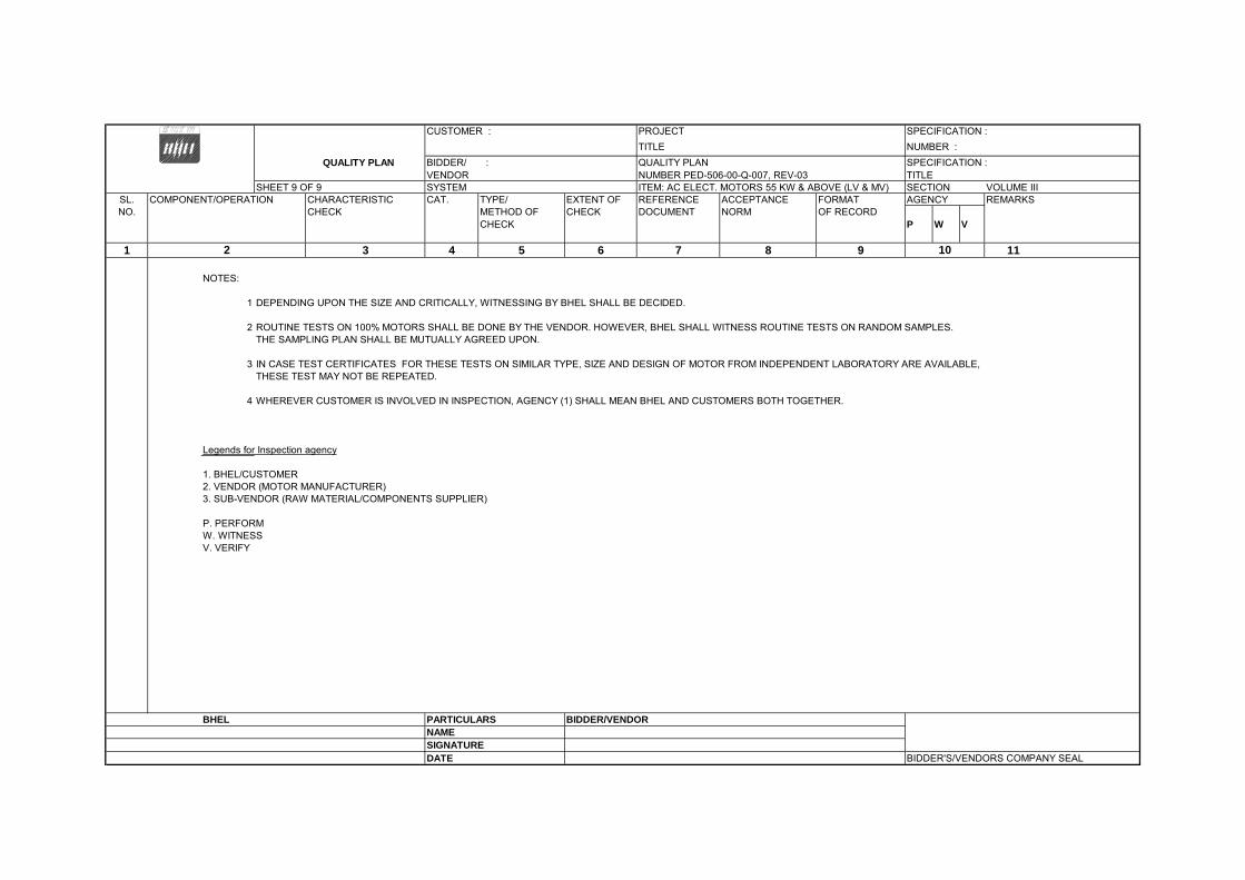
1 DEPENDING UPON THE SIZE AND CRITICALLY, WITNESSING BY BHEL SHALL BE DECIDED.
2 ROUTINE TESTS ON 100% MOTORS SHALL BE DONE BY THE VENDOR. HOWEVER, BHEL SHALL WITNESS ROUTINE TESTS ON RANDOM SAMPLES.THE SAMPLING PLAN SHALL BE MUTUALLY AGREED UPON.
3 IN CASE TEST CERTIFICATES FOR THESE TESTS ON SIMILAR TYPE, SIZE AND DESIGN OF MOTOR FROM INDEPENDENT LABORATORY ARE AVAILABLE, THESE TEST MAY NOT BE REPEATED.
4 WHEREVER CUSTOMER IS INVOLVED IN INSPECTION, AGENCY (1) SHALL MEAN BHEL AND CUSTOMERS BOTH TOGETHER.
Legends for Inspection agency
1. BHEL/CUSTOMER2. VENDOR (MOTOR MANUFACTURER)3. SUB-VENDOR (RAW MATERIAL/COMPONENTS SUPPLIER)
P. PERFORMW. WITNESSV. VERIFY
BHEL PARTICULARS BIDDER/VENDORNAMESIGNATUREDATE BIDDER'S/VENDORS COMPANY SEAL
102

TITLE : TECHNICAL SPECIFICATION SPEC. NO. PE-TS-405-165-N003
FOR VOLUME : IIB
SELF CLEANING STRAINERS (SCS) SECTION : D
REV. NO. 0 DATE :15.07.2014
SHEET 1of 1
SECTION D3
STANDARD TECHNICAL SPECIFICATION
FOR C&I SYSTEMS

DATA SHEET FOR PRESSURE / DIFFERENTIAL PRESSURE GAUGE
SPECIFICATION NO.:
VOLUME SECTION REV. NO. DATE: SHEET 1 OF 2
Data Sheet No.: PE-DC-999-145-I026-A
TECHNICAL REQUIREMENTS FOR PRESSURE / DIFFERENTIAL PRESSURE GAUGE TO BE FILLED-UP /CONFIRMED
BY BIDDER (TO BE FILLED BY PURCHASER)
FOR
M N
O. P
EM
-666
6-0
GENERAL MANUFACTURER
MODEL NUMBER
TECHNICAL SENSING ELEMENT BOURDON DIAPHRAGM
(BOURDON FOR HIGH PRESS AND DIAPHRAGM FOR LOW PRESS APPLICATION)
MATERIAL SENSING ELEMENT – AISI 316 SS MOVEMENT – AISI 304 SS CASING – DIE CAST AL SS
ENCLOSURE CLASS: IP-55 IP-65 EXPL PROOF PAINT: ENAMEL EPOXY
DIAL
SIZE: 150 MM COLOR: WHITE NUMERALS: BLACK SCALE: LINEAR, 270° ARC GRADUATED IN METRIC UNITS
CASE COLOUR : BLACK
SPAN/ ZERO ADJUSTMENT INT. MICRO SCREW
RANGE SELECTION SHOULD COVER 125% OF OPRATING PARAMETER
OVER RANGE PROTECTION 1.5 TIMES OF FSD BLOW OUT DISC REQUIRED
SWITCHING FACILITY (IF APPLICABLE) NOT REQUIRED
TYPE MICRO SWITCH OTHER
NO. / TYPE OF CONTACTS 2 NOS. SPDT
CONTACT RATING 5A 230V AC, 0.25A 220V DC
SETTING RANGE FIELD ADJUSTABLE OVER FULL RANGE
REPEATABILITY + 1% OF FSR
POWER SUPPLY 230V AC 110V AC
PERFORMANCE ACCURACY + 1% OR BETTER OF FULL SCALE DEFLECTION
CONNECTION PROCESS M20 x 1.5 (M) ½” NPT (M) ½” NPT (F) OTHER
LOCATION BOTTOM
ACCESSORIES NAME PLATE / METAL TAG SS
OTHER
SIPHON FOR STEAM, SNUBBER FOR PUMP DISCHARGE, CHEMICAL SEAL DIAPHRAGM FOR CORROSSIVE, OIL SERVICES and SLURRY APPLICATION TO BE PROVIDED
OTHER REQUIREMENT INSTRUMENT LIST
INSTRUMENT LIST COMPRISING OF TAG NO., SERVICE, DESIGN/OPERATING PRESSURE & TEMPERATURE TO BE ATTACHED
QUALITY REQUIREMENT CHECK LIST FOR PG/DPG REFER CHECK LIST NO PE-CL-999-145-I 026-0

CHECK LIST FOR
PRESSURE / DIFFERENTIAL PRESSURE GAUGE (Mechanical Auxiliary Packages)
SPECIFICATION NO.: VOLUME SECTION REV. NO. DATE:
SHEET 2 OF 2 Data Sheet No.: PE-CL-999-145-I026-0
FOR
M N
O. P
EM
-666
6-0
SL NO
TESTS/CHECKS
QUANTM OF CHECK
REFERENCE DOC. ACCEPTANCE NORMS
AGENCY
REMARKS
P W V 1.0
CHECK FOR APPROVED TECHINCAL REQUIREMENT/ DATA SHEET
MFR TO CARRY OUT ROUTINE TEST ON 100%. WHEN MATL CORELATION ARE NOT AVAILABLE MFR’S COMPLIANCE TO BE PROVIDED
1.1 DIAL SIZE 100% M C C 1.2 MODEL NO/TAG NO 100% M C C 1.3 RANGE/SCALE 100% M C C 1.4 END CONNECTION 100% M C C 1.5 SWITCH CONTACT RATING & NOS
100% M C C
2.0
CALIBRATION
2.1 ACCURACY 100% M C B 2.2 REPEATABILITY (FOR SWITCH)
100% M C B
2.3 SET POINT ADJUSTMENT FOR SWITCH
100% M C C
3.0 OVER PRESSURE & LEAK TEST
100% M C C
4.0 OPERATION OF PR. RELEIF DEVICE
ONE PER TYPE
M C C
5.0
REVIEW OF T.C. FOR MATERIAL OF--
5.1 SENSOR FOR LOT
- - B
5.2 MOVEMENT - - B 5.3 PROCESS CONNECTION - - B
5.4 HOUSING - - B 6.0 REVIEW OF T.C. FOR
DEGREE OF PROTECTION TYPE TEST - - B
7.0 REVIEW OF T.C. FOR CONTACT RATING OF SWITCH
ONE PER TYPE
- - B
8.0 ACCESSORIES AS APPLICABLE
100% M C C
LEGEND: M: MANUFACTURER/ SUB CONTRACTOR, C: CONTRACTOR/ NOMINATED INSP AGENCY, B: BHEL. P: PERFORM, W: WITNESS, V: VERIFICATION. NOTE: CONTRACTOR TO PROVIDE COMPLIANCE CERTIFICATE FOR TESTS/CHECKS VERIFIED BY CONTRACTOR AND SUBMIT THE SAME ALONGWITH TEST CERTIFICATES TO BE VERIFIED BY BHEL.


CLAUSE NO. TECHNICAL REQUIREMENTS
NORTH KARANPURA STPP (3X660 MW)
EPC PACKAGE
TECHNICAL SPECIFICATIONS SECTION – VI, PART-B
BID DOC. NO.: CS-4410-001-2
SUB-SECTION-IIIC-07 INSTRUMENTATION
CABLES
PAGE 11 OF 12
manufacturers regarding pulling tensions and cable bends. Cables damaged in any way during installation shall be replaced at the expense of the Contractor.
10.00.00 FIELD MOUNTED LOCAL JUNCTION BOXES
(i) No. of ways 12/24/36/48/64/72/96/128 with 20% spares terminals.
(ii) Material and Thickness
4mm thick Fiberglass Reinforced Polyester (FRP).
(iii) Type Screwed at all four corners for door. Door gasket shall be of synthetic rubber.
(iv) Mounting clamps and accessories
Suitable for mounting on walls, columns, structures etc. The brackets, bolts, nuts, screws, glands required for erection shall be of SS, included in Bidders scope of supply.
(v) Type of terminal blocks
Rail mounted cage-clamp type suitable for conductor size upto 2.5 mm2. A M6 earthing stud shall be provided.
(vi) Protection Class IP: 55 minimum for indoor & IP-65 minimum for outdoor applications.
(vii) Grounding To be provided.
(viii) Color RAL 7305.
11.00.00 CONDUITS
11.01.00 Conduits shall be generally used for interconnecting cables from field instruments to Local JB’s. All rigid conduits, couplings and elbows shall be hot dipped galvanised rigid mild steel in accordance with IS: 9537 Part-I (1980) and Part-II (1981). The conduit interior and exterior surfaces shall have continuous zinc coating with an overcoat of transparent enamel lacker or zinc chromate. Flexible conduit shall be heat resistant lead coated galvanized steel with , water leak, fire and rust proof protected for the areas of Mills,Drum, Main Steam, RH steam Air Heaters and Furnace, BFPDT’s .
And for remaining applications, water leak, fire and rust proof flexible GI conduits shall be provided. The temperature rating of flexible conduit shall be suitable for actual application.
11.02.00 All rigid conduit fittings shall conform to the requirements of IS: 2667, 1976. Galvanized steel fitting shall be used with steel conduit. All flexible conduit fittings shall be liquid tight, galvanized steel. The end fittings shall be compatible with the flexible conduit supplied.
11.03.00 Conduit sealing, explosion proof, dust proof and other types of special fittings shall be provided as required by these specifications and shall be consistent with the area and equipment with which they are installed. Fittings installed outdoors and in damp locations shall be sealed and gasketed. Hazardous area fittings and conduits sealing shall conform with NEC requirements for the area classification.

NO
RTH
KA
RA
NPU
RA
STP
P (3
X 6
60 M
W)
EPC
PA
CK
AG
E
TEC
HN
ICA
L SP
ECIF
ICA
TIO
N
SEC
TIO
N-V
I, PA
RT-
B
BID
DO
C N
O.:C
S-44
10-0
01-2
SU
B-S
ECTI
ON
-E-6
2 PR
OC
ESS
CO
NN
ECTI
ON
& P
IPIN
GPa
ge 1
of 1
Proc
ess
Con
nect
ion
& P
ipin
g TE
STS
ITE
MS
Visual ®
GA, BOM, Layout of component & construction feature®
Dimension ®
Paint Shade/thickness ®
Flattening,flaring,hydrotest,hardness check as per ASTM standard (A)
Component Ratings ®
Wiring ®
Make, Model, Type, Rating®
IR & HV ®
Review of TC for instrument/devices (R)
Accessability of TBs/Devices ®
Illumination,grounding ®
Tubing ®
Leak/Hydro test(A)
Chemical/physical properties of material (A)
Proof pressure test,Dismantling & reassembly test,Hydrulic impulse and vibration test (R)
Tests as per standards & specification
Loca
l Ins
trum
ent e
nclo
sure
Y
Y Y
Y
Y Y
Y Y
Y Y
Y Y
Y
Loca
l ins
trum
ents
rack
s Y
Y Y
Y
Y Y
Y Y
Y Y
Y Y
Y
Junc
tion
Box
Y Y
Y Y*
Y
Y Y
Gau
ge B
oard
Y
Y Y
Y
Y
Y
Y
Y
Y
Impu
lse
pipe
s an
d tu
bes
Y
Y
Y
Y
Y
Soc
ket w
eld
fittin
gs A
NS
I B-
16.1
1 Y
Y
Y
Y
Y
Com
pres
sion
fitti
ngs
Y
Y
Y
Y
Y Y
In
stru
men
t val
ves
& V
alve
m
anifo
lds
Y
Y
Y
Y
Y
Cop
per t
ubin
gs A
STM
B75
Y
Y
Y
*-
appl
icab
le fo
r pai
nted
junc
tion
boxe
s.
Not
e: R
-Rou
tine
Test
A- A
ccep
tanc
e Te
st
Y –
Tes
t app
licab
le
Not
e: T
his
is a
n in
dica
tive
list o
f tes
ts/c
heck
s. T
he m
anuf
actu
rer i
s to
furn
ish
a de
taile
d qu
ality
pla
n in
dica
ting
the
Pra
ctic
es a
nd P
roce
dure
ado
pted
alo
ngw
ith re
leva
nt s
uppo
rting
doc
umen
ts.

SPECIFICATION
FOR MOTORISED VALVE ACTUATOR
SPECIFICATION NO.: PE-SS-999-145-I007
VOLUME II B
SECTION D
REV. NO. 03 DATE: 20.06.14
SHEET 1 OF 3
Data Sheet A & B
DATA SHEET-A (TO BE FILLED BY PURCHASER)
DATA SHEET-B
(TO BE FILLED-UP BY BIDDER)
FOR
M N
O. P
EM
-666
6-0
GENERAL*
* PROJECT 3 X 660 MW STPP
OFFER REFERENCE
* TAG NO. SERVICE
* DUTY ON / OFF INCHING
* LINE SIZE (inlet/outlet): MATERIAL
* VALVE TYPE GLOBE GATE REG. GLOBE BUTTERFLY
* OPENING / CLOSING TIME
* WORKING PRESSURE
AMBIENT CONDITION SHALL BE SUITABLE FOR CONTINUOUS OPERATION UNDER AN AMBIENT TEMP. OF 0-55 DEG C AND RELATIVE HUMIDITY OF 0-95%
VALVE SEAT TEST PRESS BIDDER TO SPECIFY
REQUIRED VALVE TORQUE BIDDER TO SPECIFY
ACTUATOR RATED TORQUE BIDDER TO SPECIFY
CONSTRUCTION AND SIZING
CONSTRUCTION TOTALLY ENCLOSED, WEATHER PROOF, IP:55
MECHANICAL POSITION INDICATOR TO BE PROVIDED FOR 0-100% TRAVEL
BEARINGS DOUBLE SHIELDED, GREASE LUBRICATED ANTI-FRICTION.
GEAR TRAIN FOR LIMIT SWITCH/TORQUE SWITCH OPERATION
METAL (NOT FIBRE GEARS). SELF-LOCKING TO PREVENT DRIFT UNDER TORQUE SWITCH SPRING PRESSURE WHEN MOTOR IS DE-ENERGIZED.
SIZING
OPEN/CLOSE AT RATED SPEED AGAINST DESIGNED DIFFERENTIAL PRESSURE AT 90% OF RATED VOLTAGE. FOR ISOLATING SERVICE THREE SUCCESSIVE OPEN-CLOSE OPERATIONS OR 15 MINS. WHICHEVER IS HIGHER. FOR INCHING /REGULATING SERVICE - 150 STARTS/HR MINIMUM.
HANDWHEEL
* REQUIRED YES NO
* ORIENTATION TOP MOUNTED SIDE MOUNTED
*TO DISENGAGE AUTOMATICALLY DURING MOTOR OPERATION.
ELECTRIC ACTUATOR
ACTUATOR MAKE/MODEL BIDDER TO SPECIFY MOTOR MAKE / MODEL / TYPE / RATING (KW) BIDDER TO SPECIFY
@ MOTOR TYPE SQUIRREL CAGE INDUCTION MOTOR, STARTING CURRENT LIMITED TO SIX TIMES THE RATED CURRENT-INCLUSIVE OF I.S. TOLERANCE
ACTUATOR APPLICABLE WIRING DIAGRAM
ENCLOSED (BIDDER TO CONFIRM) A: DRG. NO. 3-V-MISC-24227 R00 B: DRG. NO. 3-V-MISC-24550 R00 C: DRG. NO. 3-V-MISC-24283 R00 D: DRG. NO. 4-V-MISC-90271 R11 E: For Thyristor based Integral starter, Bidder/Vendor to furnish wiring diagram
COLOUR SHADE BLUE (RAL 5012) ENAMEL …….
PAINT TYPE (## Refer Notes) ENAMEL EPOXY …….
SHAFT RPM BIDDER TO SPECIFY
OLR SET VALUE BIDDER TO SPECIFY
@ STARTING / FULL LOAD CURRENT BIDDER TO SPECIFY
NO. OF REV FOR FULL TRAVEL BIDDER TO SPECIFY
@ PWR SUPP TO MTR / STARTER 415V +/- 10 % , 3PH,3 W, AC 50 HZ +/- 5 %
@ CONTROL VOLTAGE REQUIREMENT TO BE DERIVED FROM THE POWER SUPPLY TO THE STARTER 230 V 110 V AC/24V DC

SPECIFICATION
FOR MOTORISED VALVE ACTUATOR
SPECIFICATION NO.: PE-SS-999-145-I007
VOLUME II B
SECTION D
REV. NO. 03 DATE: 20.06.14
SHEET 2 OF 3
Data Sheet A & B
DATA SHEET-A (TO BE FILLED BY PURCHASER)
DATA SHEET-B
(TO BE FILLED-UP BY BIDDER)
FOR
M N
O. P
EM
-666
6-0
MOTOR BEARING WITH 2 EARTH TERMINALS
DOUBLE SHIELDED, GREASE LUBRICATED ANTI FRICTION
@ ENCLOSURE CLASS OF MOTOR IP 67 FOR OUTDOOR & IP 55 FOR INDOOR(TOTALLY ENCLOSED SELF VENTILATED)
@ INSULATION CLASS CLASS-F TEMP. RISE LIMITED TO CLASS-B
@ WINDING TEMP PROTECTION THERMOSTAT (3 Nos.,1 IN EACH PHASE) ---------------------------------------------------------
SINGLE PHASE / WRONG PHASE SEQUENCE PROTECTION REQUIRED
INTEGRAL STARTER
INTEGRAL STARTER REQUIRED NOT REQUIRED
TYPE OF SWITCHING DEVICE CONTACTORS THYRISTORS
TYPE CONVENTIONAL SMART (NON-INTRUSIVE) IF SMART (NOT APPLICABLE)
a) SERIAL LINK INTERFACE INTEGRAL FIELD MOUNTED
b) SERIAL LINK PROTOCOL FOUNDATION FIELD-BUS PROFI-BUS DEVICE NET …………
c) SERIAL LINK MEDIA TWISTED PAIR Cu-CBL CO-AXIAL Cu-CBL OFC
d) HAND HELD PROGRAMMER REQUIRED NOT REQUIRED e) TYPE OF HAND HELD PROGRAMMER BLUETOOTH INFRARED ..............
f) MASTER STATION REQUIRED NOT REQUIRED
g) MASTER STN INTRFACE WITH DCS MODBUS TCP/IP
h) DETAILS OF SPECIAL CABLE ENCLOSED NOT REQUIRED
STEP DOWN CONT. TRANSFORMER REQUIRED
OPEN / CLOSE PB REQUIRED NOT REQUIRED
STOP PB REQUIRED NOT REQUIRED
INDICATING LAMPS REQUIRED NOT REQUIRED
LOCAL REMOTE S/S REQUIRED NOT REQUIRED
STATUS CONTACTS FOR MONITORING REQUIRED NOT REQUIRED
INTEGRAL STARTER DISTURBED SIGNAL
REQUIRED (O/L RELAY OPERATED, CONT./POWER SUPPLY FAILED, S/S IN LOCAL, TORQUE SWITCH OPTD. MID WAY)
INTERPOSING RELAY/OPTO COUPLER (Applicable for integral Starter)
TYPE OF ISOLATING DEVICE INTERPOSING RELAY OPTO COUPLER EITHER
QUANTITY 2 NOs. 3 NOs.
DRIVING VOLTAGE 20.5 – 24V DC _____________V DC
DRIVING CURRENT 125mA MAX _____________mA MAX
LOAD RESISTANCE > 192 ohms - <25 k ohms > _______ohms - < __________ohms
TORQUE SWITCH (Not Applicable for Smart Actuator) ($$ Refer Notes)
MFR & MODEL NO. BIDDER TO SPECIFY
OPEN / CLOSE 1 No. 2Nos. / 1 No. 2Nos
CONTACT TYPE 2 NO + 2 NC
RATING 5A 240V AC AND 0.5A 220V DC
CALIBRATED KNOBS(OPEN&CLOSE TS) REQUIRED FOR SETTING DESIRED TORQUE
ACCURACY +3% OF SET VALUE
LIMIT SWITCH (Not Applicable for Smart Actuator) ($$
MFR & MODEL NO. BIDDER TO SPECIFY
OPEN : INT : CLOSE 1 No 2 Nos. 1 No.
2Nos.
CONTACT TYPE 2 NO + 2 NC

SPECIFICATION
FOR MOTORISED VALVE ACTUATOR
SPECIFICATION NO.: PE-SS-999-145-I007
VOLUME II B
SECTION D
REV. NO. 03 DATE: 20.06.14
SHEET 3 OF 3
Data Sheet A & B
DATA SHEET-A (TO BE FILLED BY PURCHASER)
DATA SHEET-B
(TO BE FILLED-UP BY BIDDER)
FOR
M N
O. P
EM
-666
6-0
Refer Notes) RATING (AC / DC) 5A 240V AC AND 0.5A 220V DC
Limit switches shall be silver plated with high conductivity and non-corrosive type. Contact rating shall be sufficient to meet the requirement of control system subject to a minimum of 60 V, 6 VA rating. Protection class shall be IP 55.
POSITION TRANSMITTER
POSITION TRANSMITTER (For inching duty applications) REQUIRED NOT REQUIRED
MFR & MODEL NO. BIDDER TO SPECIFY
TYPE ELECTRONIC (2 WIRE) R/I CONVERTER ELECTRONIC (2 WIRE) CONTACTLESS
SUPPLY 24V DC ………
OUTPUT 4-20mA
ACCURACY + 1% FS
SPACE HEATER
@SPACE HEATER REQUIRED
@ POWER SUPPLY (NON INTEGRAL) 230V AC,1 PH.,50 Hz
@ POWER SUPPLY (INTEGRAL) POWER SUPPLY DERIVED FROM MAIN POWER SUPPLY AVAILABLE AT ACTUATOR END.
@ RATING
TERMINAL BOX
ACTUATOR/MOTOR TERMINAL BOX REQUIRED
ENCL CLASS ACTUATOR/MOTOR T.B. IP 67 @………
@ EARTHING TERMINAL REQUIRED
PLUG & SOCKET(9 PIN) (FOR COMMD, LS/TS FEED BACK, PoT)
REQUIRED NOT REQUIRED 2 NOS. ----------------
CABLE GLANDS
@ POWER CABLE GLAND SIZE:-----------------------
@ SPACE HEATER CABLE GLAND SIZE:-----------------------
OTHER CONTROL CABLE GLANDS-1 1No. for BFV of CW PUMP(Cable size 2Px1.5mm2)
OTHER CONTROL CABLE GLANDS-2 QUANTITY & SIZE :-----------------------

SPECIFICATION
FOR MOTORISED VALVE ACTUATOR
SPECIFICATION NO.: PE-SS-999-145-I007
VOLUME II B
SECTION D
REV. NO. 03 DATE: 20.06.14
SHEET 4 OF 3
Data Sheet A & B
DATA SHEET-A (TO BE FILLED BY PURCHASER)
DATA SHEET-B
(TO BE FILLED-UP BY BIDDER)
FOR
M N
O. P
EM
-666
6-0
WEIGHT TOTAL WEIGHT (ACTUATOR + ACCESSORIES) BIDDER TO SPECIFY _________________ Kg.
NOTES:
1. SCOPE: DESIGN, MANUFACTURE, INSPECTION, TESTING AND DELIVERY TO SITE OF ELECTRIC ACTUATOR FOR INCHING OR OPEN / CLOSE DUTY. 2. CODES & STANDARDS: DESIGN AND MATERIALS USED SHALL COMPLY WITH THE RELEVANT LATEST NATIONAL AND INTERNATION STANDARD. AS A MINIMUM,
THE FOLLOWING STANDARDS SHALL BE COMPLIED WITH: IS-9334, IS-2147, IS-2148, IS-325, IS-2959, IS-4691 AND IS-4722
3. TEMPERATURE RISE SHALL BE RESTRICTED TO 70 DEG. C FOR AMBIENT TEMPERATURE OF 50 DEG C. 4. CABLE GLANDS OF DOUBLE COMPRESSION TYPE, BRASS MATERIAL SHALL BE PROVIDED. 5. THE TORQUE SWITCHES SHALL BE PROVIDED WITH MECHANICAL LATCHING DEVICE TO PREVENT OPERATION WHEN UNSEATING FROM THE END POSITIONS.
THE LATCHING DEVICE SHALL UNLATCH AS SOON AS THE VALVE LEAVES THE END POSITION. IF SUCH PROVISION IS NOT POSSIBLE, THE TORQUE SWITCHES SHALL BE BYPASSED BY END-POSITION LIMIT SWITCHES WHICH OPENS ON VALVE LEAVING END POSITION.THESE LIMIT SWITCHES ARE ADDITIONAL TO THE NUMBER OF LIMIT SWITCHES SPECIFIED ELSEWHERE.
6. THE MOTOR SHALL OPERATE SATISFACTORILY UNDER THE +/- 10% SUPPLY VOLTAGE VARIATION AT RATED FREQUENCY, -5% TO +3% VARIATION IN
FREQUENCY AT RATED SUPPLY VOLTAGE, SIMULTANEOUS VARIATION IN VOLTAGE & FREQUENCY THE SUM OF ABSOLUTE PERCENTAGE NOT EXCEEDING 10%. 7. THE MOTOR SHALL BE SUITABLE FOR DIRECT ON LINE STARTING.
$$ TORQUE SWITCH & LIMIT SWITCH SHALL ACT INDEPENDENT OF EACH OTHER. TANDEM OPERATION IS NOT ACCEPTABLE. ## EPOXY PAINT IS RECOMMENDED FOR COASTAL AREAS.
8. It shall be posiible to operate the actuator locally. Lockable local/remote selection shall be provided on the actuator. 9. Position indicator shall be provided for 0 to 100 % travel 10. Wiring shall be suitable voltage grade copper wire.
.
PREPARED BY CHECKED BY APPROVED BY VENDOR COMPANY SEAL
NAME Madhav gupta Mayank kesharwani Bharat Singh NAME
SIGNATURE SIGNATURE
DATE 22.07.2014 22.07.2014 22.07.2014 DATE NOTES* = TO BE FILLED BY MPL (LEAD AGENCY). @= TO BE FILLED BY ES

CLAUSE NO. TECHNICAL REQUIREMENTS
NORTH KARANPURA STPP (3X660 MW)
EPC PACKAGE
TECHNICAL SPECIFICATIONS SECTION – VI, PART-B
BID DOC. NO.: CS-4410-001-2 SUB-SECTION-IIIC-12
CONTROL DESK & PANELS PAGE 1 OF 4
1.00.00 CONTROL DESK & PANELS
1.01.00 GENERAL
1.01.01 All control desk, panels, LVS panel etc. shall be furnished fully wired with necessary provision for convenience outlets, internal lighting, grounding, ventilation, space heating, anti-vibration pads, internal piping & accessories as required for completeness of the system.
1.01.02 All panels, desks, cabinets shall be free standing type & have bottom / top entry for cables to be finalised application wise during detailed engineering stage. The bottom of desk & cabinets shall be sealed with bottom plate, compression cable glands (double for field and single for inside rooms) and fire proof sealing material to prevent ingress of dust and propagation of fire. Sufficient number of power receptacles with disconnect switches shall be installed within all panels/desk.
1.01.03 Exterior steel surface shall be sand blasted, ground smooth, filled, primed, sanded and smooth enamel painted to give a good finish subject to minimum paint thickness of 65-75 microns for sheet thickness of 3 mm and 50 microns for sheet thickness of 2mm. The exact color shall be finalised during detailed engineering.
1.01.04 The design shall conform to the EN ISO 11064 (Ergonomical design of control room), Part-1,2 and 3.
2.00.00 CONTROL DESK & PANEL
2.01.00 GENERAL
2.01.01 The exact dimensions, material, construction details, grounding, general arrangement etc. of Control Desk etc. shall be as per the actual requirement and shall be finalised during detailed engineering and subjected to Employer’s Approval. For bidding purpose, the length of the desk/ panel and CD mounted devices are given in Appendix-I to Part-A, Section-VI.
2.01.02 For control desk mounted instruments/ devices etc., which are to be powered from UPS, all required conversion of interface equipments / accessories to make such devices compatible with UPS supply shall be provided. All necessary hardware like Input switches/ fuse unit for each feeder as well as switch fuse unit for each instrument/ device on the power supply line shall be provided. From UPS, redundant feeders shall be provided with suitably rated MCB and provision of fast auto changeover of UPS feeders.
2.02.00 Control Desk (CD) Control desk shall be Modular, non-welded construction free standing table top type with front & back cover constructed of 1.6 mm thick CRCA steel plates . The tabletop of the control desk shall be arc-shaped for mounting TFT monitors & mice for SG, TG, BOP (irrespective of scope of supply) and synchroscope. TFT monitors and synchroscope shall be provided with adjustable mounting arrangement. The work surface of control desk shall be 30mm thick with the top 12mm of Acrylic Solid Surface (ASS) and the remaining 18mm of laminated medium density fiber board. Work surface shall be made of two different colors at same level and seamlessly joined in each section. The structure frame shall consist of extruded aluminum top and bottom horizontal beams and vertical support tensioned together to form an integrated, finished curvilinear shaped frame. Vertical & Horizontal supports, minimum 2.5mm and 2mm thick respectively, have to be provided for the structure frame. Extreme side legs shall be illuminated type and should complete the overall form and aesthetics of the desk. It shall have concealed cable &

CLAUSE NO. QUALITY ASSURANCE
NORTH KARANPURA STPP (3 X 660 MW)
EPC PACKAGE
TECHNICAL SPECIFICATION SECTION-VI, PART-B
BID DOC NO.:CS-4410-001-2
SUB-SECTION-E-70 CONTROL DESK Page 1 of 1
CONTROL DESK, LVS PANEL, PLC PANEL, SMOKE DETECTOR, FIRE ALARM & CONTROL SYSTEM
TESTS
ITEMS
Vis
ual ®
GA
, BO
M ,L
ay O
ut o
f com
pone
nts
®
Dim
ensi
ons
®
Pai
nt S
hade
/Thi
ckne
ss/A
dhes
ion
®
Alig
nmen
t of S
ectio
n ®
Com
pone
nt R
atin
g/ M
ake
/ Typ
e ®
Wiri
ng ®
IR &
HV
®
Rev
iew
of T
C fo
r ins
trum
ents
/ Dev
ices
/ Rec
orde
rs,
Indi
cato
rs/ o
saic
Item
s/ T
rans
duce
rs ®
Acc
essi
bilit
y of
TB
S/ D
evic
es ®
Illum
inat
ion
®
Func
tiona
l Che
ck fo
r Con
trol E
lem
ent ,
Mim
ic ®
Test
as
per I
EC 1
131
® *
Test
as
per S
td ®
& (
A)
1. Control Desk Y Y Y Y Y Y Y Y Y Y Y Y Y 2. LVS Panel Y Y Y Y Y Y Y Y Y Y 3. Annunciation, Control, PLC Panel
Y Y Y Y Y Y Y Y Y Y Y Y
4.Smoke Detectors( UL-268,EN-54 PT-7), Heat Detectors( UL-521/EN 54 PT-5 ) Annunciation/ Control Panel ( UL -864, EN-54, PT-2)
Y
Note: 1) Detailed procedure of Environmental Stress Screening test shall be as per Quality Assurance Programme in General Technical Conditions
2) This is an indicative list of test/ checks. The manufacturer is to furnish a detailed quality plan indicating the Practice and Procedure alongwith relevant supporting documents. *Applicable for PLC Y - Test Applicable , ® - Routine Test (A) - Acceptance Test


TITLE : TECHNICAL SPECIFICATION SPEC. NO. PE-TS-405-165-N003
FOR VOLUME : IIB
SELF CLEANING STRAINERS (SCS) SECTION : D
REV. NO. 0 DATE :15.07.2014
SHEET 1of 1
LIST OF SUB-VENDORS


