cover sheet - w. o. grubb€¦ · 1 5425 (#5380 & #6257 consolidated)---1104---f8hl link-belt...
TRANSCRIPT
15425 (#5380 & #6257 consolidated)---1104---F8HL
HTC-8640HLLink-Belt Cranes
Technical DataSpecifications & Capacities
Telescopic Boom Truck Crane40 ton (36.29 metric ton)
CAUTION: This material is supplied forreference use only. Operator must refer toin---cab Crane RatingManual andOperator’sManual to determine allowable crane liftingcapacities and assembly and operatingprocedures.
HTC-8640

5425 (#5380 & #6257 consolidated)---1104---F8HL
HTC-8640HL Link-Belt Cranes
15425 (#5380 & #6257 consolidated)---1104---F8HL
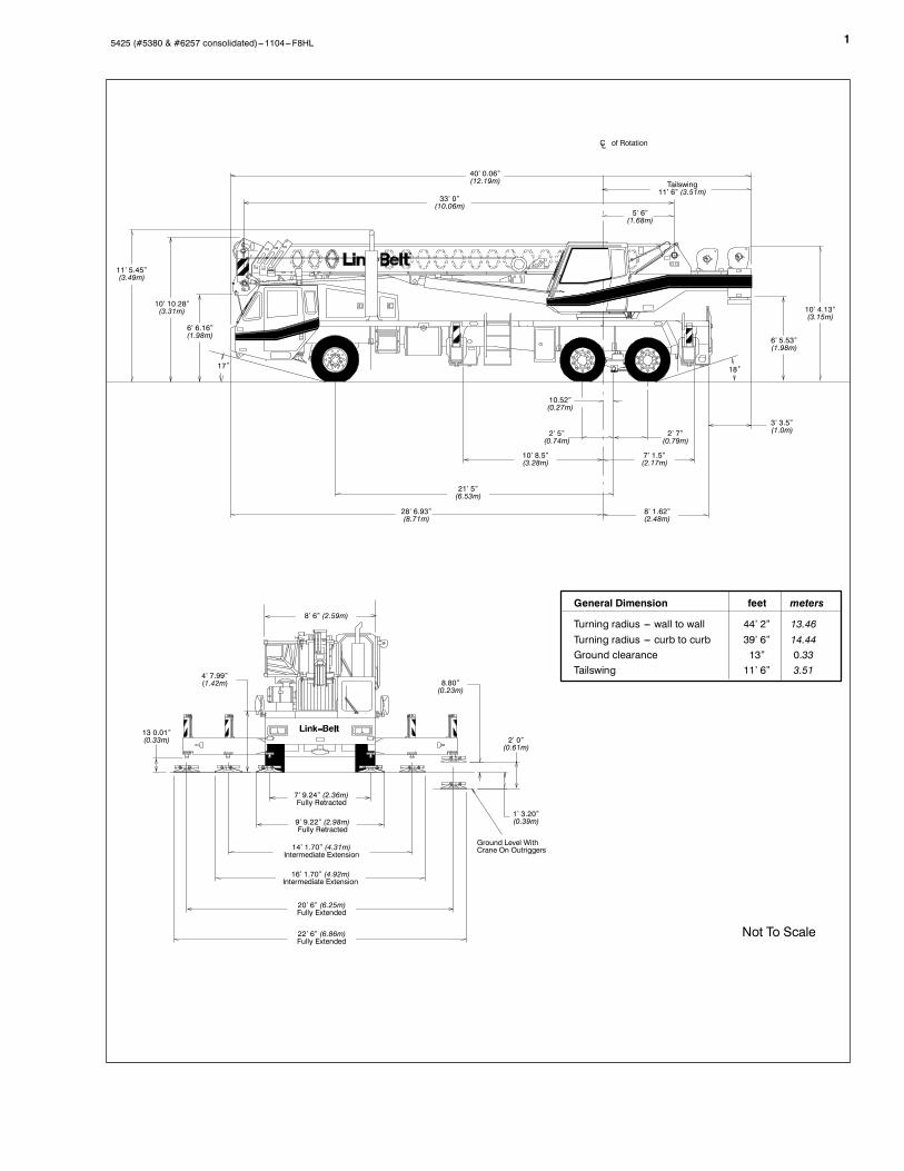
Not To Scale
General Dimension feet meters
Turning radius --- wall to wall 44’ 2” 13.46Turning radius --- curb to curb 39’ 6” 14.44Ground clearance 13” 0.33Tailswing 11’ 6” 3.51
7’ 9.24” (2.36m)Fully Retracted
9’ 9.22” (2.98m)Fully Retracted
14’ 1.70” (4.31m)Intermediate Extension
16’ 1.70” (4.92m)Intermediate Extension
20’ 6” (6.25m)Fully Extended
22’ 6” (6.86m)Fully Extended
Ground Level WithCrane On Outriggers
1’ 3.20”(0.39m)
2’ 0”(0.61m)
8.80”(0.23m)
4’ 7.99”(1.42m)
13 0.01”(0.33m)
8’ 6” (2.59m)
28’ 6.93”(8.71m)
8’ 1.62”(2.48m)
21’ 5”(6.53m)
10’ 8.5”(3.28m)
7’ 1.5”(2.17m)
2’ 5”(0.74m)
2’ 7”(0.79m)
10.52”(0.27m)
3’ 3.5”(1.0m)
18˚17˚
6’ 6.16”(1.98m)
10’ 10.28”(3.31m)
11’ 5.45”(3.49m)
33’ 0”(10.06m)
40’ 0.06”(12.19m)
5’ 6”(1.68m)
6’ 5.53”(1.98m)
10’ 4.13”(3.15m)
CL of Rotation
Tailswing11’ 6” (3.51m)
HTC-8640

2 5425 (#5380 & #6257 consolidated)---1104---F8HL
Upper StructureJ BoomPatented DesignS Boom side plates have diamond shapedimpressions for superior strength to weightratio and 100,000 psi (689.5mPa) steelangle chords for lateral stiffness
S Boom telescope sections are supportedby top, bottom, and adjustable side wearshoes to prevent metal to metal contact
BoomS 33---105 ft (10.06---32.00m) four---sectionfull power boom
S Two mode boom extensionS The basic mode is the full power, synchro-nized mode of telescoping all sections pro-portionally to 105 ft (32.00m)
S The exclusive “A---max” mode (or mode‘A’) extends only the inner mid section to57 ft (17.37m) offering increased capaci-ties for in---close, maximum capacity picks
S Mechanical boom angle indicator
Boom HeadS Four 16.5 in (0.42m) root diameter nylonsheaves to handle up to eight parts of wirerope
S Easily removable wire rope guardsS Rope dead end lugs provided on eachside of boom head
S Boom head designed for quick reeve ofhook block
Boom ElevationS One Link---Belt designed hydraulic cylin-der with holding valve and bushing in eachend
S Hand control for controlling boom eleva-tion from ---3˚ to +78˚
Optional Auxiliary Lifting SheaveS Single 16.5 in (0.42m) root diameter nylonsheave with removable wire rope guard,mounted to boom
S Use with one or two parts of line off the op-tional front winch
S Does not affect erection of fly or use ofmain head sheaves for multiple reeving
OptionalS 25--- ton (22.7mt) quick reeve hook blockS 40--- ton (36.3mt) quick reeve hook blockS 8.5--- ton (7.7mt) hook ballS Boom floodlight
J FlyOptionalS 28.5 ft (8.69m) one---piece lattice fly, stow-able, offsettable to 2˚, 20˚, and 40˚
S 28.5---51 ft (8.69---15.54m) two---piece (bi---fold) fly, stowable, offsettable to 2˚, 20˚,and 40˚
J Cab and ControlsEnvironmental Ultra---CabtS Laminated fibrous composite material; iso-lated from sound with acoustical fabric in-sulation
S Windows are tinted and tempered safetyglass
S Sliding rear and right side windows andswing---up roof window for maximumvisibility and ventilation
S Slide---by---door opens to 3 ft (0.91m)width
S Six---way adjustable seat for maximumoperator comfort
S Hand---held outrigger controls and sightlevel bubble located in cab
S Diesel cab heaterS Pull---out Cabwalkt S Circulatingfan
S Audible swing alarm S Warning hornS Fire extinguisher S Cup holderS 12---volt accessory outlet S Sun screenS Electric windshield wiper S Hand throttleS Windshield washer S MirrorsS Top hatch window wiper S Dome light
OptionalS Amber strobe lightS Amber rotating beaconS Hydraulic heaterS Air conditioning
ControlsHydraulic controls (joystick type) for:S Swing S Main winchS Optional auxiliary winch S Boom hoistFoot controls for:S Boom telescopeS Swing brakeS Engine throttle
OptionalS Auxiliary winchS SIngle axis controls
Cab InstrumentationCornerpost---mounted gauges for:S Hydraulic oil temperatureS Audio/Visual warning systemS Tachometer S Oil pressureS Voltmeter S FuelS Water temperature
J Rated CapacityLimiterS Microguard 434 Graphic audio---visualwarning system built into dash with anti---two block and function limiters
Operating data available includes:S Machine configuration.S Boom length S Boom angleS Head height S Radius of loadS Allowed load S Actual loadS % of allowed load
Presettable alarms include:S Maximum and minimum boom anglesS Maximum tip heightS Maximum boom lengthS Swing left/right positionsS Operator defined area alarm is standardS Anti--- two block weight designed for quickreeve of hook block
OptionalS Internal RCL light bar: Visually informsoperator when crane is approaching maxi-mum load capacity with a series of threelights; green, yellow, and red
S External RCL light bar: Visually informsground crew when crane is approachingmaximum load capacity kickouts and pre-settable alarms with a series of three lights;green, yellow, and red
J SwingS Bi---directional hydraulic swing motormounted to a planetary reducer for 360_continuous smooth swing at 2.8 rpm
S Swing park brake --- 360˚, electric overhydraulic (spring applied, hydraulic re-leased) multi---disc brake mounted on thespeed reducer. Operated by toggle switchin overhead control console.
S Swing brake --- 360˚, foot operated, hy-draulic applied disc brake mounted on thespeed reducer
S Swing lock --- Standard; two position trav-el lock operated from the operator’s cab
S CounterweightS Standard --- Bolted to upper structureframe. 9,700 lb (4 400kg) consisting of4,700 lb (2 132kg) base counterweight and5,000 lb (2 268kg) of removable counter-weights.
OptionalS 360˚ swing lock. Meets New York Cityrequirements.

35425 (#5380 & #6257 consolidated)---1104---F8HL
J Hydraulic SystemMain PumpS One gear pump with a total of four sec-tions
S Combined pump capacity of 131 gpm(488Lpm)
S Powered by carrier engine through powertake---off (PTO)
S Spline type pump disconnect, mechanical-ly activated pump disconnect engaged/disengaged from carrier cab
S Maximum system operating pressure is3,350 psi (23 098kPa)
S O--- ring face seals technology usedthroughout with hydraulic oil cooler stan-dard
Steering / Fifth Outrigger PumpS Single gear type pump, 6 gpm (23Lpm).Powered by carrier engine through frontgear housing
S Max. pump operating pressure is 2,000 psi(13 790kPa). Reservoir --- 131 gal (507.2L)capacity. One diffuser for deaeration.
FiltrationS One 10---micron filter located inside hy-draulic reservoir
S Accessible for easy replacement
Control valvesS Five separate pilot operated control valvesallow simultaneous operation of all cranefunctions
J Load Hoist SystemStandardS 2M main winch with grooved laggingS Two---speed motor and automatic brakeS Power up/down mode of operationS Bi---directional piston--- type hydraulic mo-tor driven through planetary reduction unitfor positive control under all load condi-tions
S Asynchronous parallel double crossovergrooved drums minimize rope harmonicmotion
S Pressure compensated winch circuit pro-vides balanced oil flow to both winches forsmooth, simultaneous operation
S Rotation resistant wire ropeS Drum rotation indicators
Line Pulls and SpeedsS Maximum available line pull 13,010 lb(5 901kg) and maximum line speed of 480fpm (146 m/min) on 10.63 in (0.27m) rootdiameter grooved drum
OptionalS 2M auxiliary winch with two---speed motor,automatic brake, and winch function lock-out. Power up/down modes
S Hoist drum cable followersS Third wrap indicators
CarrierJ TypeS 8 ft 6 in (2.59m) wide, 257 in (6.53m)wheelbase. 6 x 4 drive --- standard.
FrameS 100,000 psi (689.5MPa) steel, doublewalled construction with integral 100,000psi steel outrigger boxes
OptionalS Carrier mounted storage boxesS Pintle hookS Electric and air connections for trailers
J AxlesFrontS Single, 83.22 in (2.11m) trackRearS Tandem, 73.41 in (1.86m) track. 6.17 to 1.0ratio with interaxle differential with lockout(6.64:1 ratio with automatic transmission)
J SuspensionFront axleS Leaf spring suspension
Rear axleS Air--- ride, bogie---beam type, suspension
J WheelsStandardS Hub piloted aluminum disc
J TiresStandard FrontS 425/65R22.5 (Load range “L”) single tube-less radials
Standard RearS 12R22.5 (Load range “H”) dual tubelessradials
J BrakesServiceS Full air brakes on all wheel ends with auto-matic slack adjustors. Dual circuit withmodulated emergency brakes.S Front --- 16.5 x 6 S---Cam brakesS Rear --- 16.5 x 7 S---Cam brakes
Parking/EmergencyS One spring set, air released chamber perrear axle end
S Parking brake applied with valve mountedon carrier dash
S Emergency brakes apply automaticallywhen air drops below 40 psi (275.8kPa) inboth systems
J SteeringS Sheppard rack and pinion designOptionalS Remote drive and steer
J TransmissionStandardS Eaton RTX---11609B; 9 speeds forward, 2reverse
OptionalS Automatic Allison MD 3066, 65:1 high,3.49:1 low
AuxiliaryS Eaton 2A---92, two speed--- High: 1.0:1Low: 2.3:1 (with automatic transmissiononly)
J ElectricalS Two 12---volt batteries provide 12---voltstarting. 160---amp alternator
S 1,400 cold cranking amps availableS 12---volt operating system
LightsS Four dual beam sealed headlightsS Front, side, and rear directional signalsS Stop, tail and license plate lightsS Rear and side clearance lightsS Hazard warning lights
J OutriggersS Three position operation capabilityS Four hydraulic, telescoping beam and jackoutriggers
S Vertical jack cylinders equipped with inte-gral holding valve
S Beams extend to 20 ft 6 in (6.25m) center-line--- to---centerline and retract to within 8 ft6 in (2.59m) overall width
S Equipped with stowable, lightweight 24 in(0.61m) diameter aluminum floats
S Standard fifth outrigger, 16 in (0.41m) selfstoring steel pad is operable from groundor operator’s cab
S Hand---held controls and sight levelbubble located on carrier deck
Confined Area Lifting Capacities(CALCt) SystemS The crane is operational in one of the threeoutriggers positions and operational inconfined areas in two positions (intermedi-ate and full retraction. The threeoutrigger positions are:
S Full extension --- 20 ft 6 in (6.25m)S Intermediate position --- 14 ft 1.70 in (4.31m)S Full retraction --- 7 ft 9.24 in (2.36m)S Capacities are available with the outriggerbeams in the intermediate and full retrac-tion positions
S When the outrigger position levers(located on the outrigger beams) areengaged, the operator can set the crane inthe intermediate or full retraction outriggerposition without having to leave the cab

4 5425 (#5380 & #6257 consolidated)---1104---F8HL
J Carrier CabS One---man cab of laminated fibrous com-posite material acoustical insulation withcloth covering
Equipped with:S Air--- ride, six---way adjustable operator’sseat
S Four---way adjustable tilting and lockablesteering wheel
S Door and windows locksS Left---hand and right---hand rear view mirrorsS Sliding right---hand and rear tinted windowsS Roll up/down left---hand tinted window
S Desiccant--- type air dryerS Steps to upper, lower cab and rear carrierS 120---volt electric engine block heateS Back---up warning alarmS Tow hooks and shacklesS Aluminum fenders with ground controloutriggers
S Electric windshield wiper and washerS Travel lights S HornS Fire extinguisher S AshtrayS 36,000 BTU heater S DefrosterS Dome light S Cruise controlS Mud flaps
OptionalS Rotating BeaconS Amber Strobe LightS Air conditioning
Cab instrumentationS Illuminated instrument panel speedometerS Tachometer S HourmeterS Fuel gauge S FusesS Oil pressure gauge S OdometerS Turn signal indicator S VoltmeterS Water temperature gaugeS Front and rear air pressure gaugesS Audio/visual warning systemS Automotive type ignition
J Carrier Speeds (Manual Transmission --- Standard tires)Gear
High Low Hi Rev. Lo Rev. Low Rev. @700rpm Low @700 rpm
Gear8 7 6 5 4 3 2 1 Low Rev. Rev. Low Rev. Low
Ratio 0.73 1.00 1.38 1.95 2.79 3.83 5.28 7.47 12.57 3.43 13.14 13.14 12.57
Speedmph 57.92 42.28 30.64 21.68 15.15 11.04 8.01 5.66 3.36 12.33 3.22 1.07 1.12
Speed km/hr 93.42 68.19 49.42 35.00 24.44 17.81 12.92 9.13 5.42 19.89 5.42 1.72 1.64
J EngineEngine --- standard Cummins ISL 330 with Jake BrakeCylinders --- cycleBoreStrokeDisplacementMaximum brake hp.Peak torqueElectric systemFuel capacityAlternatorCrankcase capacity
6 / 44.49 in (114mm)5.69 in (145mm)540 cu. in. (8 849cm3)345 @ 1,900 rpm; 330 @ 2,100 rpm1,150 ft lb (1 559.2J)@ 1,300 --- 1,400 rpm12---volt neg. ground / 12 volt starting75 gallons (284L)12 volt, 160 amps29 qt (28L)
J Axle LoadsBase machine with standard 33---105 ft (10.06 --- 32.00m) four section boom, 2M main winch G VW ¡
Upper Facing FrontBase machine with standard 33---105 ft (10.06 --- 32.00m) four section boom, 2M main winchwith 2---speed hoisting and power up/down, 450 ft (137m), 5/8 in (19mm) wire rope, 8 x 4, G.V.W.¡
Front Axle Rear Axlewith 2 speed hoisting and power up/down, 450 ft (137m), 5/8 in (19mm) wire rope, 8 x 4,8.5 ft (2.59m) carrier with Cummins ISL 330 Engine, 75 gal (284L) fuel, aluminum fenders,d 9 700 lb (4 400k ) t i ht
lb kg lb kg lb kg( ) g , g ( ) , ,and 9,700 lb (4 400kg) counterweight. 62,185 28 207 16,677 7 565 45,508 20 642Left side carrier aluminum storage box 57 26 14 6 43 20Right side carrier aluminum storage boxS
57 26 14 6 43 20Six---speed automatic transmission and two---speed auxiliary transmission with engine brakeAi diti i C i b
576124
26156
223135
10161
35311
1605Air conditioning --- Carrier cab
Pi tl h k / i d l t i l h k
12432
5615
1359
614
---1141
---519Pintle hook w/air and electrical hook---ups
D i i i b
32200
1591
---9236
---4107
41---36
19---16Driver in carrier cab
C b h t bl (h d li )
200110
9150
236---8
107---4
---36118
---165Cab heater assembly (hydraulic)
Air conditioning Operator cab
110315
50143
---8---35
---4---16
118350
5159Air conditioning --- Operator cab
Rear winch roller
31577
14335
---35---31
---16---14
350108
15949Rear winch roller
Front winches with two speeds and 450 ft (137 2m) of wire rope
77312
35141
---31---93
---14---43
108405
49184Front winches with two speeds and 450 ft (137.2m) of wire rope
Front winch roller
31277
14135
---93---22
---43---10
40599
18445Front winch roller
Remove rear winch rope (450 ft)
77---365
35---166
---22161
---1073
99---526
45---239Remove rear winch rope (450 ft)
Remove front winch rope (450 ft)
---365---365
---166---166
161120
7354
---526---485
---239---220Remove front winch rope (450 ft)
360˚ Mechanical House Lock
---36560
---16627
120---2
54---1
---48562
---22028360˚ Mechanical House Lock
Fly brackets to boom base section for fly options
60116
2753
---262
---128
6254
2824Fly brackets to boom base section for fly options
28 5 ft (8 69m) offsettable fly w/ATB weight (stowed)
1161,184
53537
62839
28381
54345
2415628.5 ft (8.69m) offsettable fly w/ATB weight (stowed)
28.5---51 ft (8.69 ---15.54m) offsettable fly w/ATB weight (stowed)
1,1841,757
537797
8391,141
381518
345616
15627928.5---51 ft (8.69 ---15.54m) offsettable fly w/ATB weight (stowed)
Floodlight to front of boom base section
1,75710
7975
1,14113
5186
616---3
279---1Floodlight to front of boom base section
25---ton (22.7mt) hook block stowed behind bumper (3---sheaves)
10670
5304
13784
6356
3---114
1---5225---ton (22.7mt) hook block stowed behind bumper (3---sheaves)
40---ton (36.3mt) hook block stowed behind bumper (4---sheaves)
670780
304354
784913
356414
114---133
52---6040---ton (36.3mt) hook block stowed behind bumper (4---sheaves)
Hookball to front bumper
780360
354163
913421
414191
133---61
60---28Hookball to front bumper
Auxiliary arm w/ATB switch to boomhead
360110
16350
421169
19169
61---59
28---20
¡ Adjust gross vehicle weight & axle loading according to component weight. Note: All weights are¦ 3%
Axle Maximum Load @ 65 mph (105km/h)Front
Rear
22,700 lb (10 297kg) --- aluminum disc wheels
47,250 lb (21 432kg) --- aluminum disc wheels

55425 (#5380 & #6257 consolidated)---1104---F8HL
WARNINGREAD AND UNDERSTAND THE OPERATOR’S AND SAFETY MANUALS AND THE FOLLOWINGINSTRUCTIONS AND RATED LIFTING CAPACITIES BEFORE OPERATING THE CRANE.OPERATION WHICH DOES NOT FOLLOW THESE INSTRUCTIONS MAY RESULT IN AN ACCIDENT.
OPERATING INSTRUCTIONSGENERAL:1. Rated lifting capacities in pounds as shown on liftcharts pertain to this crane as originally manufacturedand normally equipped. Modifications to the crane oruse of optional equipment other than that specifiedcan result in a reduction of capacity.
2. Construction equipment can be dangerous ifimproperly operated or maintained. Operation andmaintenance of this crane must be in compliance withthe information in the Operator’s, Parts, and SafetyManuals supplied with this crane. If these manualsare missing, order replacements through thedistributor.
3. The operator and other personnel associated with thiscrane shall read and fully understand the latestapplicable American National Standards ASME B30.5safety standards for cranes.
4. The rated lifting capacities are based on cranestanding level on firm supporting surface.
SET UP:1. The crane shall be leveled on a firm supportingsurface. Depending on the nature of the supportingsurface, it may be necessary to have structuralsupports under the outrigger pontoons or tires tospread the load to a larger bearing surface.
2. When making lifts on outriggers, all tires must be freeof supporting surface. All outrigger beams must beextended to the same length; fully retracted,intermediate extended, or fully extended. The frontbumper outrigger must be properly extended.
3. When making lifts on tires, they must be inflated tothe recommended pressure. (See Operation note 20and Tire Inflation.)
4. Before swinging boom to over side position on tires,boom sections must be fully retracted not exceedinga 72_ boom angle.
5. For required parts of line, see Wire Rope Capacityand Winch Performance.
6. Before setting up on intermediate outriggers,retracted outriggers, or tires, refer to Working RangeDiagrams and rated lifting capacities to determineallowable crane configurations.
OPERATION:1. Rated lifting capacities at rated radius shall not beexceeded. Do not tip the crane to determineallowable loads. For concrete bucket operation,weight of bucket and load shall not exceed 80% ofrated lifting capacities. For clamshell bucketoperation, weight of bucket and bucket contents isrestricted to a maximum weight of 6,000 pounds or80% of rated lifting capacity, whichever is less. Formagnet operation, weight of magnet and load isrestricted to a maximum weight of 6,000 pounds or80% of rated lifting capacity, whichever is less. Forclamshell and magnet operation, maximum boomlength is restricted to 50 ft and the boom angle isrestricted to a minimum of 35 degrees. Lifts witheither fly erected is prohibited for both clam andmagnet operation.
2. Rated lifting capacities shown on fully extendedoutriggers do not exceed 85% of the tipping loads.Rated lifting capacities shown on intermediateextended or fully retracted outriggers are determinedby the formula, rated load = (tipping load --- 0.1 Xload factor)/1.25. Rated lifting capacities shown ontires do not exceed 75% of the tipping loads. Tippingloads are determined by SAE crane stability test codeJ---765.
3. Rated lifting capacities in the shaded areas arebased on structural strength or hydraulic limitationsand have been tested to meet minimum requirementsof SAE J---1063cantilevered boom crane structures---method of test.The rated lifting capacities in non---shaded areas arebased on stability ratings. Some capacities arelimited by a maximum obtainable 78_ boom angle.
4. Rated lifting capacities include the weight of the hookball/block, slings, bucket, magnet and auxiliary liftingdevices. Their weights must be subtracted from thelisted rated capacity to obtain the net load which canbe lifted. Rated lifting capacities include the deductfor either fly stowed on the base of the boom. Fordeducts of either fly erected, but not used, seeCapacity Deductions For Auxiliary Load HandlingEquipment.
6 5425 (#5380 & #6257 consolidated)---1104---F8HL
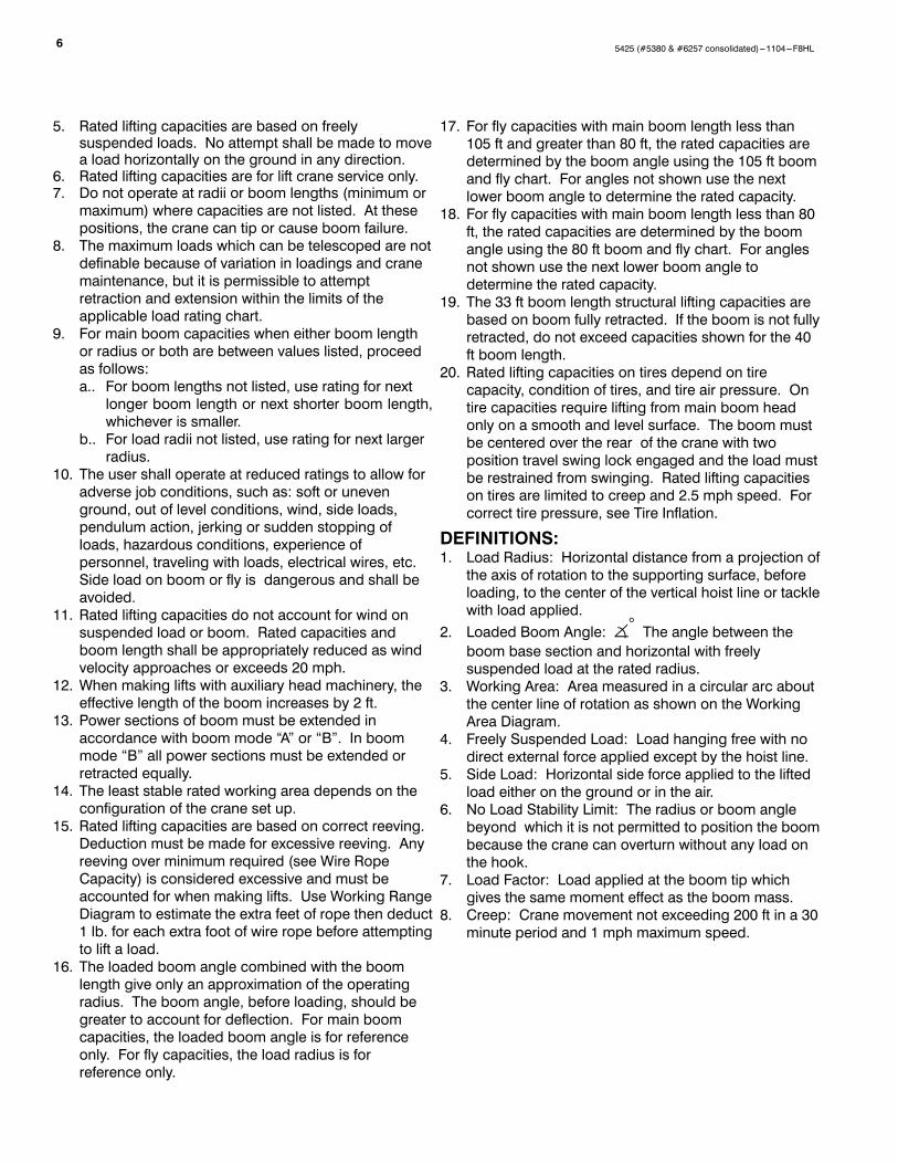
5. Rated lifting capacities are based on freelysuspended loads. No attempt shall be made to movea load horizontally on the ground in any direction.
6. Rated lifting capacities are for lift crane service only.7. Do not operate at radii or boom lengths (minimum ormaximum) where capacities are not listed. At thesepositions, the crane can tip or cause boom failure.
8. The maximum loads which can be telescoped are notdefinable because of variation in loadings and cranemaintenance, but it is permissible to attemptretraction and extension within the limits of theapplicable load rating chart.
9. For main boom capacities when either boom lengthor radius or both are between values listed, proceedas follows:a.. For boom lengths not listed, use rating for nextlonger boom length or next shorter boom length,whichever is smaller.
b.. For load radii not listed, use rating for next largerradius.
10. The user shall operate at reduced ratings to allow foradverse job conditions, such as: soft or unevenground, out of level conditions, wind, side loads,pendulum action, jerking or sudden stopping ofloads, hazardous conditions, experience ofpersonnel, traveling with loads, electrical wires, etc.Side load on boom or fly is dangerous and shall beavoided.
11. Rated lifting capacities do not account for wind onsuspended load or boom. Rated capacities andboom length shall be appropriately reduced as windvelocity approaches or exceeds 20 mph.
12. When making lifts with auxiliary head machinery, theeffective length of the boom increases by 2 ft.
13. Power sections of boom must be extended inaccordance with boom mode “A” or “B”. In boommode “B” all power sections must be extended orretracted equally.
14. The least stable rated working area depends on theconfiguration of the crane set up.
15. Rated lifting capacities are based on correct reeving.Deduction must be made for excessive reeving. Anyreeving over minimum required (see Wire RopeCapacity) is considered excessive and must beaccounted for when making lifts. Use Working RangeDiagram to estimate the extra feet of rope then deduct1 lb. for each extra foot of wire rope before attemptingto lift a load.
16. The loaded boom angle combined with the boomlength give only an approximation of the operatingradius. The boom angle, before loading, should begreater to account for deflection. For main boomcapacities, the loaded boom angle is for referenceonly. For fly capacities, the load radius is forreference only.
17. For fly capacities with main boom length less than105 ft and greater than 80 ft, the rated capacities aredetermined by the boom angle using the 105 ft boomand fly chart. For angles not shown use the nextlower boom angle to determine the rated capacity.
18. For fly capacities with main boom length less than 80ft, the rated capacities are determined by the boomangle using the 80 ft boom and fly chart. For anglesnot shown use the next lower boom angle todetermine the rated capacity.
19. The 33 ft boom length structural lifting capacities arebased on boom fully retracted. If the boom is not fullyretracted, do not exceed capacities shown for the 40ft boom length.
20. Rated lifting capacities on tires depend on tirecapacity, condition of tires, and tire air pressure. Ontire capacities require lifting from main boom headonly on a smooth and level surface. The boom mustbe centered over the rear of the crane with twoposition travel swing lock engaged and the load mustbe restrained from swinging. Rated lifting capacitieson tires are limited to creep and 2.5 mph speed. Forcorrect tire pressure, see Tire Inflation.
DEFINITIONS:1. Load Radius: Horizontal distance from a projection ofthe axis of rotation to the supporting surface, beforeloading, to the center of the vertical hoist line or tacklewith load applied.
2. Loaded Boom Angle: (° The angle between theboom base section and horizontal with freelysuspended load at the rated radius.
3. Working Area: Area measured in a circular arc aboutthe center line of rotation as shown on the WorkingArea Diagram.
4. Freely Suspended Load: Load hanging free with nodirect external force applied except by the hoist line.
5. Side Load: Horizontal side force applied to the liftedload either on the ground or in the air.
6. No Load Stability Limit: The radius or boom anglebeyond which it is not permitted to position the boombecause the crane can overturn without any load onthe hook.
7. Load Factor: Load applied at the boom tip whichgives the same moment effect as the boom mass.
8. Creep: Crane movement not exceeding 200 ft in a 30minute period and 1 mph maximum speed.

75425 (#5380 & #6257 consolidated)---1104---F8HL
BOOM EXTENSIONBoom Mode “A”
Boom Mode “B”
Only inner mid sectiontelescopes
Inner mid, outer mid and tipsections telescopesimultaneously.
Inner Mid Section288” Stroke
Base Section
Inner MidSection
288” StrokeBase Section
Outer MidSection
288” StrokeTip Section288” Stroke
33
40
50
57
Boom Length (ft)
Boom Length (ft)
33
40
50
60
70
80
90
100
105
TIRE INFLATIONTire Size Operation Tire Pressure (psi)
12R22.5 Creep2.5 mph
120110
PONTOON LOADINGS
Maximum Pontoon Load:Maximum Pontoon
Ground Bearing Pressure:
61,750 lb 137 psi
CAPACITY DEDUCTIONS FOR AUXILIARYLOAD HANDLING EQUIPMENT
Load Handling Equipment: lbAuxiliary Head Attached 100
25--ton quick reeve 3--sheave hook block (see hook block for actualweight) 670
40--ton quick reeve 4--sheave hook block (see hook block for actualweight) 780
8.5--ton hook ball (see hook ball for actual weight) 360Lifting From Main Boom With: lb
28.5 ft or 51 ft fly stowed on base (see operation note 4) 0
28.5 ft offset fly erected but not used 2,600
51 ft offset fly erected but not used 4,800
Lifting From 28.5 ft Offset Fly With:22.5 ft fly tip erected but not used PROHIBITED
22.5 ft fly tip stowed on 28.5 ft offset fly PROHIBITED
Note: Capacity deductions are for Link--Belt supplied equipment only.
WINCH PERFORMANCEWinch Line Pulls
Drum Rope Capacity (ft)Wire Two Speed Winch
Drum Rope Capacity (ft)WireRopeL
Low Speed High SpeedLayer Total
RopeLayer Available* (lb) Available (lb)
Layer Total
1 13,010 6,418 77 77
2 11,768 5,805 85 162
3 10,742 5,299 93 255
4 9,881 4,874 101 356
5 9,148 4,513 109 465
*Maximum lifting capacity: Type RB Rope=9,080, Type ZB Rope=11,080
WIRE ROPE CAPACITYMaximum Lifting Capacities Based On Wire Rope Strength
Parts of Line5/8” 5/8”
NotesParts of LineType RB Type ZB
Notes
1 9,080 11,080
2 18,160 22,160 Capacities shown are in pounds3 27,240 33,240
Capacities shown are in poundsand working loads must not ex-
d th ti th it4 36,320 44,320
and working loads must not exceed the ratings on the capacitycharts in the Crane Rating Manual.
5 45,400 55,400charts in the Crane Rating Manual.
S O f6 54,480 66,480 Study Operator’s Manual for wirerope inspection procedures and
7 63,560 77,560rope inspection procedures andsingle part of line applications.
8 72,640 88,640
single part of line applications.
9 81,720 y
LBCE DESCRIPTION
TYPE RB
TYPE ZB
18 X 19 Rotation Resistant -- Compact Strand,High Strength Preformed, Right Regular Lay
36 X 7 Rotation Resistant -- Extra ImprovedPlow Steel -- Right Regular Lay
HYDRAULIC CIRCUIT PRESSURE SETTINGSFunction Pressure (PSI)
Front And Rear Winch 3,100Outriggers 3,000Boom Hoist 3,350Telescope 3,000Swing 1,500Steering 2,000Bumper Outrigger 650Pilot Control 500
WORKING AREAS
LongitudinalC of HTCL
Center ofRotation
Note: These Lines Determine The Limiting Position Of AnyLoad For Operation Within Working Areas Indicated.
LongitudinalC of HTCLHTC on Tires
Center OfRotation
HTC on Outriggers
Rear
360_ Chart
Front
C OutriggerPontoonL
See Note
See Note
Boom Centered Over Rear
Side
Side
C BoomL
C Rear AxleL
C Front AxleL
8 5425 (#5380 & #6257 consolidated)---1104---F8HL
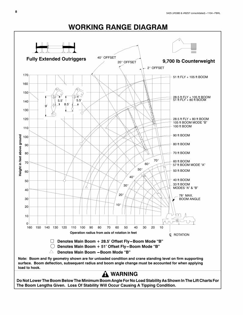
WORKING RANGE DIAGRAMHeightinfeetaboveground
DoNot LowerTheBoomBelowTheMinimumBoomAngleForNoLoadStabilityAsShown InTheLiftChartsForThe Boom Lengths Given. Loss Of Stability Will Occur Causing A Tipping Condition.
WARNING
Note: Boom and fly geometry shown are for unloaded condition and crane standing level on firm supportingsurface. Boom deflection, subsequent radius and boom angle change must be accounted for when applyingload to hook.
Operation radius from axis of rotation in feet
0
10
20
30
40
50
60
80
90
100
110
120
ROTATION
70
130
140
150
160
V Denotes Main Boom + 28.5’ Offset Fly---Boom Mode “B”f Denotes Main Boom + 51’ Offset Fly---Boom Mode “B”Denotes Main Boom ---Boom Mode “B”
170
28.5 ft FLY + 105 ft BOOM
28.5 ft FLY + 80 ft BOOM105 ft BOOM MODE “B”100 ft BOOM
50 ft BOOM
40 ft BOOM33 ft BOOMMODES “A” & “B”
78_ MAX.BOOM ANGLE
160 150 140 130 120 110 100 90 80 70 60 50 40 30 20 10
Fully Extended Outriggers 9,700 lb Counterweight
CL
40_ OFFSET20_ OFFSET
2_ OFFSET
9’
5.5’8.5’
5.5’
51 ft FLY + 105 ft BOOM
51 ft FLY + 80 ft BOOM
90 ft BOOM
80 ft BOOM
70 ft BOOM
60 ft BOOM57 ft BOOM MODE “A”
20_
30_
40_
50_
60_70_
10_

95425 (#5380 & #6257 consolidated)---1104---F8HL
FULL EXTENSION
MAIN BOOM “A”
Rated Lifting Capacities InPoundsFully Extended OutriggersSee Set Up Note 2
9,700 lb
Load 33 ft 40 ftLoadRadius(ft) ( ° 360° Over
Rear ( ° 360° OverRear
9 68.0 80,000 80,000
10 66.0 72,300 72,300 70.5 72,300 72,300
12 62.0 65,500 65,500 67.5 65,200 65,200
15 55.5 55,600 55,600 62.5 55,300 55,300
20 43.5 42,200 42,200 54.0 41,900 41,900
25 26.5 29,900 29,900 44.0 29,700 29,700
30 31.0 21,500 21,500
Min. Bm. 0 18 400 18 400 0 14 100 14 100Min. Bm.Ang/Cap
0(27.5) 18,400 18,400 0
(34.5) 14,100 14,100
LoadR di
50 ft 57 ftLoadRadius(ft) ( ° 360° Over
Rear ( ° 360° OverRear
10 75.0 67,500 67,500 77.0 43,800 43,800
12 73.0 61,200 61,200 75.0 43,800 43,800
15 69.0 53,400 53,400 72.0 42,100 42,100
20 62.5 41,600 41,600 66.5 34,300 34,300
25 55.5 29,300 29,300 61.0 28,700 28,700
30 48.0 21,300 21,300 54.5 21,100 21,100
35 39.0 16,100 16,100 47.5 16,000 16,000
40 27.5 12,400 12,400 40.0 12,300 12,300
45 30.5 9,600 9,600
50 16.0 7,600 7,600
Min. Bm. 0 9 300 9 300 0 6 900 6 900Min. Bm.Ang/Cap
0(44.5) 9,300 9,300 0
(51.5) 6,900 6,900
Note: Refer To “Capacity Deductions For Auxiliary Load Handling Equipment”. (°Loaded BoomAngle In Degrees. ( ) Reference Radius For Min. BoomAngle Capaci-ties (Shown in Parenthesis) Are In Feet.
MAIN BOOM “B”
FULL EXTENSIONRated Lifting CapacitiesIn PoundsFully Extended OutriggersSee Set Up Note 2
9,700 lb
Load 33 ft 40 ft 50 ftLoadRadius(ft) ( ° 360° Over
Rear ( ° 360° OverRear ( ° 360° Over
Rear9 68.0 80,000 80,000
10 66.0 72,300 72,300 70.5 35,000 35,000 74.5 35,000 35,000
12 62.0 65,500 65,500 67.5 35,000 35,000 72.5 35,000 35,000
15 55.5 55,600 55,600 62.5 35,000 35,000 68.5 35,000 35,000
20 43.5 42,200 42,200 54.0 35,000 35,000 62.5 35,000 35,000
25 26.5 29,900 29,900 43.5 30,700 30,700 55.5 31,100 31,100
30 31.0 22,400 22,400 47.5 23,000 23,000
35 39.0 17,700 17,700
40 27.5 14,000 14,000
Min. Bm. 0 18 400 18 400 0 13 500 13 500 0 9 200 9 200Min. Bm.Ang/Cap
0(27.5) 18,400 18,400 0
(34.5) 13,500 13,500 0(44.5) 9,200 9,200
Load 60 ft 70 ft 80 ftLoadRadius(ft) ( ° 360° Over
Rear ( ° 360° OverRear ( ° 360° Over
Rear10 77.5 35,000 35,000
12 75.5 35,000 35,000
15 72.5 35,000 35,000 75.5 35,000 35,000
20 67.5 35,000 35,000 71.5 35,000 35,000 74.5 30,700 30,700
25 62.5 31,400 31,400 67.0 31,500 31,500 71.0 26,400 26,400
30 56.5 23,200 23,200 62.5 23,400 23,400 67.0 22,900 22,900
35 50.5 18,000 18,000 57.5 18,100 18,100 62.5 18,200 18,200
40 43.5 14,300 14,300 52.0 14,500 14,500 58.5 14,600 14,600
45 35.5 11,600 11,600 46.5 11,800 11,800 53.5 11,900 11,900
50 25.0 9,500 9,500 40.0 9,700 9,700 49.0 9,900 9,900
55 33.0 8,100 8,100 43.5 8,200 8,200
60 23.0 6,700 6,700 37.5 6,800 6,900
65 31.0 5,700 5,800
70 22.0 4,700 4,800
Min. Bm. 0 6 500 6 500 0 4 600 4 600 0 3 300 3 300Min. Bm.Ang/Cap
0(54.5) 6,500 6,500 0
(64.5) 4,600 4,600 0(74.5) 3,300 3,300
Load 90 ft 100 ft 105 ftLoadRadius(ft) ( ° 360° Over
Rear ( ° 360° OverRear ( ° 360° Over
Rear20 77.0 27,400 27,400
25 73.5 23,500 23,500 76.0 21,000 21,000 76.5 17,500 17,500
30 70.0 20,500 20,500 73.0 18,700 18,700 74.0 17,500 17,500
35 66.5 18,100 18,100 70.0 16,500 16,500 71.0 15,700 15,700
40 63.0 14,700 14,700 66.5 14,600 14,600 68.0 13,800 13,800
45 59.0 12,000 12,000 63.0 12,000 12,000 65.0 12,100 12,100
50 55.0 9,900 9,900 59.5 10,000 10,000 61.5 10,000 10,000
55 50.5 8,300 8,400 56.0 8,400 8,400 58.5 8,400 8,400
60 46.0 6,900 7,000 52.5 7,000 7,100 55.0 7,000 7,100
65 41.5 5,800 5,900 48.5 5,800 6,000 51.0 5,900 6,000
70 35.5 4,800 4,900 44.0 4,900 5,000 47.0 4,900 5,100
75 29.5 4,000 4,100 39.5 4,100 4,200 43.0 4,100 4,300
80 21.0 3,300 3,400 34.0 3,400 3,500 38.5 3,400 3,600
85 28.0 2,800 2,900 33.5 2,800 3,000
90 20.0 2,200 2,400 27.5 2,200 2,400
95 19.5 1,800 2,000
Min. Bm. 0 2 300 2 300 0 1 500 1 500 17.0Min. Bm.Ang/Cap
0(84.5) 2,300 2,300 0
(94.5) 1,500 1,500 17.0(96.3)
Note: Refer To “Capacity Deductions For Auxiliary Load Handling Equipment”. (°Loaded Boom Angle In Degrees. ( ) Reference Radius For Min. Boom Angle Capaci-ties (Shown In Parenthesis) Are In Feet.
10 5425 (#5380 & #6257 consolidated)---1104---F8HL
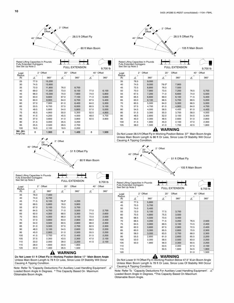
28.5 ft Offset Fly
2_ Offset
40_ Offset
20_Offset
80 ft Main Boom
Rated Lifting Capacities In PoundsFully Extended OutriggersSee Set Up Note 2 FULL EXTENSION 9,700 lb
LoadRadius
2_ Offset 20_ Offset 40_ OffsetLoadRadius(ft) ( ° 360° ( ° 360° ( ° 360°
25 77.0 15,20030 74.5 13,90035 72.0 11,900 76.0 8,70040 69.0 11,000 73.0 8,100 77.0 6,10045 66.0 10,300 70.0 7,600 74.0 5,80050 63.0 9,600 67.0 7,100 71.0 5,60055 60.0 8,900 64.0 6,700 67.5 5,40060 57.0 7,900 61.0 6,400 64.0 5,30065 53.5 6,700 57.5 6,000 60.5 5,10070 49.5 5,800 54.0 5,800 57.0 5,00075 45.5 4,900 50.0 5,300 52.5 4,90080 41.5 4,200 45.5 4,500 48.0 4,70085 37.0 3,600 41.0 3,800 42.5 3,90090 31.5 3,000 35.5 3,20095 25.5 2,500 28.5 2,700100 16.5 2,100 18.5 2,200
Min. Bm. 0 1 300 0 1 400 0 1 500Min. Bm.Ang/Cap. 0 1,300 0 1,400 0 1,500
51 ft Offset Fly
80 ft Main Boom
2_ Offset
40_ Offset
20_Offset
Rated Lifting Capacities In PoundsFully Extended OutriggersSee Set Up Note 2 FULL EXTENSION 9,700 lb
LoadRadius
2_ Offset 20_ Offset 40_ OffsetLoadRadius(ft) ( ° 360° ( ° 360° ( ° 360°
35 76.0 7,40040 74.0 6,70045 71.5 6,100 78.0* 4,20050 69.5 5,600 76.0 3,90055 67.0 5,100 73.5 3,70060 64.5 4,700 71.0 3,500 77.0 2,70065 62.0 4,300 68.5 3,300 74.5 2,60070 59.5 4,000 66.0 3,100 72.0 2,50075 57.0 3,800 63.0 2,900 69.0 2,40080 54.0 3,500 60.5 2,800 66.0 2,30085 51.0 3,300 57.5 2,700 62.5 2,30090 48.0 3,100 54.5 2,600 59.5 2,20095 45.0 2,900 51.0 2,500 55.5 2,200100 41.5 2,700 47.5 2,400 51.5 2,200105 37.5 2,300 43.5 2,300 47.0 2,100110 33.0 2,000 39.0 2,200 41.5 2,100115 28.0 1,600 33.5 1,800120 22.0 1,400 26.5 1,500
Do Not Lower 51 ft Offset Fly In Working Position Below 17_ Main Boom AngleWARNING
Do Not Lower 51 ft Offset Fly In Working Position Below 17_ Main Boom AngleUnless Main Boom Length Is 78 ft Or Less, Since Loss Of Stability Will OccurCausing A Tipping Condition.
Note: Refer To “Capacity Deductions For Auxiliary Load Handling Equipment”. (°Loaded Boom Angle In Degrees. * This Capacity Based On MaximumObtainable Boom Angle.
28.5 ft Offset Fly
2_ Offset
40_ Offset
20_Offset
105 ft Main Boom
Rated Lifting Capacities In PoundsFully Extended OutriggersSee Set Up Note 2 FULL EXTENSION 9,700 lb
LoadRadius
2_ Offset 20_ Offset 40_ OffsetLoadRadius(ft) ( ° 360° ( ° 360° ( ° 360°
35 76.5 9,00040 74.5 9,000 78.0* 7,90045 72.5 8,800 76.0 7,50050 70.0 7,900 73.5 7,200 76.5 5,70055 67.5 7,200 71.0 6,600 74.0 5,50060 65.5 6,600 69.0 6,100 71.5 5,40065 63.0 6,100 66.5 5,700 69.5 5,20070 60.5 5,500 64.0 5,300 66.5 5,00075 57.5 4,700 61.0 4,900 64.0 4,70080 54.5 4,000 58.5 4,400 61.0 4,40085 51.5 3,300 55.0 3,700 58.0 4,00090 48.5 2,800 52.0 3,100 54.5 3,30095 45.0 2,300 48.5 2,600 51.0 2,800100 41.5 1,900 45.0 2,100 47.0 2,300105 38.0 1,500 41.0 1,700 42.5 1,800
Do Not Lower 28.5 ft Offset Fly In Working Position Below 37° Main BoomAngleUnless Main Boom Length Is 86 ft Or Less, Since Loss Of Stability Will OccurCausing A Tipping Condition.
WARNING
51 ft Offset Fly
105 ft Main Boom
2_ Offset
40_ Offset
20_Offset
Rated Lifting Capacities In PoundsFully Extended OutriggersSee Set Up Note 2 FULL EXTENSION 9,700 lb
LoadRadius
2_ Offset 20_ Offset 40_ OffsetLoadRadius(ft) ( ° 360° ( ° 360° ( ° 360°
40 77.5 5,80045 75.5 5,70050 74.0 5,40055 72.0 5,100 77.5 3,70060 70.5 4,800 75.5 3,50065 68.5 4,500 73.5 3,40070 66.5 4,200 71.5 3,200 76.5 2,50075 64.5 3,900 69.5 3,100 74.5 2,40080 62.0 3,600 67.5 2,900 72.5 2,40085 60.0 3,300 65.5 2,800 70.5 2,30090 58.0 3,000 63.5 2,700 68.0 2,30095 55.5 2,800 61.0 2,600 65.5 2,200100 53.0 2,300 58.5 2,500 63.0 2,200105 50.0 1,900 56.0 2,300 60.5 2,200110 53.5 2,000 57.5 2,100115 50.5 1,600 54.5 1,900120 51.0 1,500
Do Not Lower 51 ft Offset Fly In Working Position Below 47.5°Main Boom AngleUnless Main Boom Length Is 78 ft Or Less, Since Loss Of Stability Will OccurCausing A Tipping Condition.
WARNING
Note: Refer To “Capacity Deductions For Auxiliary Load Handling Equipment”. (°Loaded Boom Angle In Degrees. *This Capacity Based On MaximumObtainable Boom Angle.

115425 (#5380 & #6257 consolidated)---1104---F8HL
This page intentionally left blank

12 5425 (#5380 & #6257 consolidated)---1104---F8HL
This page intentionally left blank

135425 (#5380 & #6257 consolidated)---1104---F8HL
This page intentionally left blank

5425 (#5380 & #6257 consolidated)---1104---F8HL
Link--Belt Construction Equipment Company Lexington, Kentucky www.linkbelt.comRLink--Belt is a registered trademark. Copyright 2004. We are constantly improving our products and therefore reserve the right to change designs and specifications.