cover - welcome to applied instruments, manufacturer of rf …€¦ · · 2008-12-19of two-way...
TRANSCRIPT

OPERATION MANUALSAT 9520
Satellite Signal Level Meter950-2150 MHz
™

SAT 9520OPERATION MANUAL
VERSION 1.1
2002
Applied Instruments, Inc.5230 Elmwood Avenue
Indianapolis, IN 46203 USAhttp://www.appliedin.com
Voice: (317) 782-4331Fax: (317) 786-9665
Toll free USA: (800) 244-2976

TABLE OF CONTENTS
FEATURES ................................................ 1STANDARD ACCESSORIES ...................... 2MEASUREMENTS .................................... 2SCAN MODE ........................................... 2EXTRAS ................................................. 3CONTROLS & CONNECTIONS ................... 5
QUICK START .......................................... 8ALIGNING THE DISH ................................ 8VERIFYING THE SYSTEM ......................... 11ASSESSING SYSTEM MARGIN ................. 12FINDING CABLE PROBLEMS ..................... 13
SETUP MODE............................................ 14GENERAL INSTRUCTIONS ........................ 15CONTRAST ............................................ 15CHANNEL PLANS .................................... 16SWITCH TYPE ......................................... 17SIGNAL LEVEL UNITS .............................. 18SIGNAL QUALITY MEASUREMENT ............ 18INCLUDE IN SCAN ................................... 19DEFAULT CONFIGURATION ..................... 20OFFSET & COMPENSATION FEATURES ..... 20
RUN MODE ............................................... 22LNB POWER ............................................ 23LNB POWER INDICATOR LED .................... 24BAR GRAPHS ......................................... 25IRD SIGNAL QUALITY INDICATOR ............. 25BIT ERROR RATE .................................... 26SIGNAL LOCK ......................................... 26

CHANNEL SELECTION .............................. 26AUDIBLE PEAKING .................................. 27AUDIBLE C/N PEAKING FEATURE ............. 29FREQUENCY DEVIATION ESTIMATE ......... 29POST-FEC BIT ERROR RATE ..................... 30
SCAN MODE............................................. 32TO START A SCAN ................................. 32SUMMARY SCREENS .............................. 32NOISE SCAN CHANNEL PLAN ................... 34
POLARITY & MULTIPLE LNBS ................... 36DUAL POLARITY LNBS ............................. 36SINGLE POLARITY LNBS .......................... 37MULTIPLE LNB ANTENNAS ...................... 37MULTI SWITCHES ................................... 37
SIGNAL LOCKING ..................................... 39SATELLITE IDENTIFICATION CARD ........... 40SATELLITE IDENTIFICATION PLANS .......... 40
BATTERY CHARGING ............................... 42BATTERY STATUS INDICATOR ................ 42BATTERY CHARGE LED ........................... 43WALL TRANSFORMER ............................. 43
DIGITAL SIGNAL MEASUREMENTS ........... 44BIT ERROR RATE .................................... 46EB/N0 .................................................... 47ES/N0 .................................................... 48
CHANNEL PLANS...................................... 49DBS PLANS ............................................ 49KU BAND SATELLITES ............................. 50SATELLITE ID PLANS ............................... 50SPECIAL PURPOSE PLANS ........................ 51FREQUENCY CHART ................................ 53

The Applied Instruments SAT 9520 is warranted againstdefects in materials and workmanship for a period oftwelve months. Applied Instruments agrees to repair orreplace any assembly or component found to be defec-tive under normal use during this period. Our obligationunder this warranty is limited solely to repairing theinstrument proved to be defective within the scope ofthe warranty when returned to the factory. Transporta-tion to the factory is to be prepaid by the customer.Authorization by Applied Instruments is required prior toshipment.
Applied Instruments assumes no liability for secondarycharges or consequential damages and, in any event,Applied Instruments’ liability for breach of warrantyunder any contract shall not exceed the purchase priceof the instrument shipped, and against which a claim ismade.
Any application recommendations made by AppliedInstruments for the use of its products are based upontests believed to be reliable, but Applied Instrumentsmakes no warranty of the results to be obtained. Thiswarranty is in lieu of all other warranties, expressed orimplied, and no representative or person is authorized torepresent or assume for Applied Instruments any liabilityin connection with the sale of our products other thanthat set forth herein.
WARRANTY

1
The SAT 9520™ Satellite Signal Level Meter facilitatesinstallation and troubleshooting of residential and commer-cial satellite systems. Its features include:
• Measuring the strength and quality of digital satellite signals• Powering single and multiple LNB (low noise block
amplifier) antennas• Identifying most satellites• Controlling multi-switches• Tuning to individual transponder frequencies• Storing field selectable channel plans
By obtaining a signal decoding lock, the SAT 9520 positivelyidentifies many DBS, Ku, and C-band satellites. Installationof two-way broadband, VSAT and DBS installations is muchquicker when the correct satellite is easily located and identi-fied.
The SAT 9520 simultaneously displays signal strength andIRD signal quality bar graphs for signal peaking, carrier-to-noise for optimizing cross polarization, and bit-error-rate forobtaining maximum rain-fade margin.
Finally, the SAT 9520’s scan feature automatically measures,collects, and summarizes the proof of performance datarequested by system providers.
FEATURES

2
STANDARD ACCESSORIES• Padded carrying case with shoulder strap• Data cable and Load9520 software• Operation Manual• Transformer for battery charging• One spare F-connector (usually in the box with the
transformer)
MEASUREMENTS• SIGNAL LEVEL
In dBm, dBmV or dBuVPresent and peak levelsNumeric and bar graph display
• SIGNAL QUALITYIRD signal meter equivalentPresent and peak levelsNumeric and bar graph display
• CARRIER-TO-NOISE RATIOC/N, Eb/N0 or Es/N0
• BIT ERROR RATE (BER)Pre-FEC BERPost-FEC BER
• FREQUENCY ACCURACYEstimated LNB frequency deviation
SCAN MODEThe Scan Mode measures each transponder in the channel plan anddisplays summary data to verify proper operation at all frequencies.
3
• Min/Max MeasurementsLeft and right hand polarity separatelySignal levelEb/N0, Es/N0 or C/NPre-FEC BER
• Adjacent Channel DifferenceCo-polar left handCo-polar right handCross-polar
EXTRAS• LNB POWER
13 or 18 volt polarity selection22 kHz tone for multiple LNB or frequency range selectionControl of most multi-switch types including DiSEqC™
• AUDIBLE PEAKING TONESignal strength indicator orC/N signal quality indicator
• CHANNEL PLANSStandard plans for major system providersMultiple satellite plans for identification within frequency bandPlan lists for different location or purposesCustom channel plans available
• BACK LIGHT
• FAST CHARGE BATTERY
• SERIAL PORT AND CABLEChannel plans and tables upgraded from internet or disk via PC
4
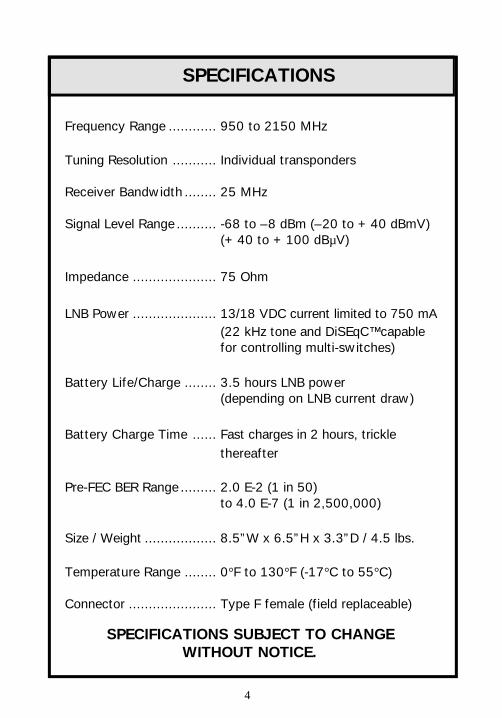
SPECIFICATIONS
SPECIFICATIONS SUBJECT TO CHANGEWITHOUT NOTICE.
Frequency Range ............ 950 to 2150 MHz
Tuning Resolution ........... Individual transponders
Receiver Bandwidth ........ 25 MHz
Signal Level Range .......... -68 to –8 dBm (–20 to +40 dBmV)(+40 to +100 dBµV)
Impedance ..................... 75 Ohm
LNB Power ..................... 13/18 VDC current limited to 750 mA(22 kHz tone and DiSEqC™ capablefor controlling multi-switches)
Battery Life/Charge ........ 3.5 hours LNB power(depending on LNB current draw)
Battery Charge Time ...... Fast charges in 2 hours, trickle thereafter
Pre-FEC BER Range ......... 2.0 E-2 (1 in 50)to 4.0 E-7 (1 in 2,500,000)
Size / Weight .................. 8.5”W x 6.5”H x 3.3”D / 4.5 lbs.
Temperature Range ........ 0°F to 130°F (-17°C to 55°C)
Connector ...................... Type F female (field replaceable)

5
CONTROLS & CONNECTIONS
NAVIGATIONBUTTONS
UNIT POWER
BATTERYCHARGER
CONNECTION
LCD DISPLAY
SIGNAL INPUT “F”CONNECTOR
CALIBRATIONCONNECTION
MODE SELECTIONBUTTONS
AUX FUNCTIONBUTTONS
BATTERY CHARGESTATUS LED
(CHARGING/FULL)

6
MODE SELECTION BUTTONS
SAT 9520 on/off
Run Mode
Setup Mode
Scan Mode
AUX FUNCTION BUTTONS
LNB power on/off and multiple LNB selection
Audio on/off
Backlight on/off
Bit Error Test (Pre and Post FEC) of selected transponder
Frequency deviation estimate (replaces BER on Runmode screen)
NAVIGATION BUTTONS
Up arrow
Down arrow
Enter

7
RF INPUT CONNECTORThis is a high quality 2 GHz “F” type connector to connect thecoaxial cable from the antenna or distribution system. Thisconnector may be replaced using a 7/16 inch wrench. The F-connector should be replaced periodically, especially if yoususpect the meter’s performance has degraded.
THE NUT ON THE 2 GHZ CONNECTOR DOES NOT SEAT FLUSHAGAINST THE CASE. SOME THREADS WILL BE VISIBLE BETWEENTHE CASE AND THE NUT; THIS IS NORMAL.
BATTERY CHARGER CONNECTIONOnly the AC wall transformer provided should be plugged intothis connector. Any other device may damage the instrument.
COMPUTER CONNECTIONThis is a serial port for connecting to a computer with the datacable provided. By using the LOAD9520 software, this interfaceallows upgrading with new or modified channel plans andinternal tuner settings.
THIS IS NOT A HEADPHONE JACK!!
!
8
The following sections of this manual contain detailed instruc-tions on using the SAT 9520, but because the unit was designedto be user-friendly, the guidelines in this section should besufficient to get you up and running quickly.
This section assumes you are installing a standard, single LNB,DIRECTV™ antenna. If not, read the section on Setup Modebefore performing the procedures in this section.
ALIGNING THE DISHComplete the following steps to ensure proper alignment of thedish antenna.
Mount the antenna according to the manufacturer’sinstructions and perform approximate alignment usingthe azimuth and elevation tables provided with theantenna.
Connect the antenna cable to the SAT 9520 and press
to turn the unit on.
Use the and arrows to select a DIRECTV™
transponder on the desired satellite. DIRECTV™ hasseveral satellites and not all transponders are used on everysatellite. A list of the transponders used on differentsatellites should be available in the system’s installationmanual or from DIRECTV™.
QUICK START
Step 2
Step 1
Step 3

9
Turn on the antenna’s LNB by pressing the
button.
Observe the signal level and lock status on the SAT9520 display. If the dish is pointed at the satellite, thelevel should be fairly high and the display should indi-cate a lock status. The “Search” indicator should bereplaced by “DIRECTV.”
More than likely, your dish will not be pointed at thesatellite; the level will be lower and the lock status willshow “Search.”
Turn on the audible peaking tone by pressing the
button. You should hear a slow beeping tone.
Slowly turn the dish slightly to the left and right. Whenthe dish is pointed at the satellite, the signal will bestronger and the audible peaking tone from the SAT9520 will beep faster. Move the dish back and forthslowly until you find the spot where the tone beepssolid.
While looking at the display, pay careful attention to thesignal level (DBM) and the IRD signal quality bar graphs.Try to obtain the highest signal strength and the highestsignal quality.
Step 4
Step 5
Step 6
Step 7

10
Fine tune the elevation by adjusting the dish up anddown until the maximum signal position is found.
Observe the locking status on the display. If“DIRECTV” is shown, you are locked onto aDIRECTV™ transponder. Check the other transpon-ders to be sure you are locked onto the correctDIRECTV™ satellite.
If “DVB-S” is shown, you are locked onto a non-DIRECTV™ transponder. Some of the orbital positionsare shared between DIRECTV™ and other systems, socheck other transponders to determine which satelliteyou are receiving.
If “Search” is shown, you may have found the wrongsatellite or the signal may be too low to obtain a lock.Check the approximate alignment and elevation settingsagain. Make sure the line of sight to the satellite is clearof obstructions; you may need to relocate the dish.
Check the peak indicator on the signal level bar graph. Ifthe narrow line extends more than one full block beyondthe thick line, the dish is not presently at the peakposition. Try adjusting it again.
Check the peak indicator on the IRD bar graph. It alsoshould not extend more than one full block beyond thethick line or you should readjust the dish to maximizethe signal quality.
NOTE: ACCEPTABLE SIGNAL LEVELS ARE DIFFERENT FOR DIFFERENT LOCATIONS AND WILL DEPEND ON THE WEATHER.
Step 8
Step 10
Step 9
Step 11

11
VERIFYING THE SYSTEMWhen the dish has been aligned, complete the following steps tocheck the complete system. This should be done at the dish tobe sure the dish and LNB are operating correctly and again atthe IRD connection to be sure there are no problems with thecabling.
Check a few channels by using the and buttons
to change channels. Check the lock status, the signallevel, and the IRD reading.
Use the Scan Mode to check all transponders. Press
and wait while the SAT 9520 measures all channels. Thistakes about 1 minute.
Check the Transponder List to verify that all validDIRECTV™ transponders for the desired satellite arelisted. Note: Some transponders are spot-beamed tocertain locations and may not be visible from yourlocation.
Press to view the Power Summary screen, check for
reasonable values:• Are all max and min power levels reasonable?• Are they within the system provider’s specifications?
Press to view the Bit Error Rate summary screen:
• Are all BER values reasonable and consistent?• An unusually high BER may indicate a problem with a particular frequency. You may want to check that transponder using Run Mode.
Step 1
Step 2
Step 5
Step 4
Step 3

12
Press to view the signal quality summary screen:
• Are these values consistent and reasonable?
Press to view the Adjacent Channel Power sum-
mary screen.• Are these values reasonable and within the system provider’s specifications?
ASSESSING SYSTEM MARGINAt this point, you should be confident that the system is work-ing correctly. Next, you should verify that the system is goodenough to tolerate some degradation in the signal (e.g. badweather).
Press to return to Run Mode and review the IRD
signal quality measurements:• Are these well within the acceptable limits or are they marginal?
Review the signal level measurements:• Is the signal strong enough?
Press to start the Post-FEC BER test. This test
provides a better indication of the available systemmargin.
Step 6
Step 7
Step 1
Step 2
Step 3

13
Check the Pre-FEC BER rate; this will typically be around 1.0E-3to 1.0E-4. A larger negative exponent indicates a lower bit errorrate. 1.0E-4 is 1 error in 10,000 bits, while 1.0E-3 is 1 error in1,000 bits. The lower the rate, the better the system margin.
Let the system run for a few minutes and watch theCorrected BER. The Corrected BER rate provides agood estimate of the system margin. The so-called“cliff effect” occurs when this rate is exceeds 1.0E-4.However, this rate takes a little while to become estab-lished, so let this test run for a minute or two.
Check the Post-FEC BER. This is the rate of errorsvisible to the customer. If this error count is not zero,there is a problem.
FINDING CABLE PROBLEMSIf the system is verified at the dish but shows a problem at the IRDconnection, there must be a problem somewhere in the cablingsystem. Multi-dwelling unit installations that contain amplifiers,splitters and a lot of cable are especially susceptible to cableproblems.
The source of these problems can be located by simply testing thesystem at various points along the path from the dish to the IRD. Ifa problem is found at some point in the cable, the problem source islocated between the point tested and the dish. If the systems resultsare good at the point tested, the problem source is located closer tothe IRD. Keep testing until the source is isolated.
Many intermittent cable faults are caused by bad crimps or brokencenter-conductors. The audible tone can help locate these faults.Turn the tone on and then shake or bend the cable. If the tonechanges significantly, a fault is indicated.
Step 4
Step 5

14
Before using the SAT 9520, you may need to change some setupparameters to tailor its operation to your system and specificneeds. Setup Mode presents these parameters in a scrolling listthat makes it easy to select different options.
THE SETUP PARAMETERS ARE:
Contrast Adjusts the contrast of the display screen.
Channel plan Selects the frequency plan appropriate foryour system.
Switch Type Selects the type of multi-switch control.
Units Specifies the display units for the signallevel measurement.
Quality measure Selects from three nearly equivalentmeasures of signal quality.
Include in scan Selects the system types to include inSetup Mode.
Preset Resets the instrument to factory defaults.
Level offset Allows signal level calibration to be tiedto another signal source.
C/N offset Allows C/N calibration to be to tied toanother signal source.
IRD offset Allows IRD Signal Quality to be tied toanother known source.
C/N compensation Allows the C/N compensation to beturned on or off.
SETUP MODE

15
GENERAL INSTRUCTIONSPress [SET UP] to start Setup Mode.
To change any of the parameters, use the arrow keys to positionthe blinking cursor on the item to be modified and press [EN-TER]. The prompts on the top line will then indicate that aparameter has been selected and can now be modified. Next, usethe arrow keys to select a value for that parameter and press[ENTER] again.
There are more setup parameters than the screen can display atone time. Press [UP] from the top line or [DOWN] from thebottom line to scroll the parameters in a circular fashion.
CONTRASTIt may be necessary to adjust the display contrast to make thescreen easier to read. In fact, if the contrast is too low, thescreen may not be visible at all. In that case, you may need toperform this adjustment without being able to read the screen!Don’t worry, it’s easy.

16
TO CHANGE DISPLAY CONTRAST:
• Press [SETUP] to start Setup Mode. The cursor will appear on the “Contrast” line.• Press [ENTER] to edit the contrast level.• Use the [UP] and [DOWN] until the desired contrast is displayed.• Press [ENTER] to accept the contrast.• Press [RUN] to resume measurements.
CHANNEL PLANSThe channel plan defines the frequencies and settings associatedwith each channel or transponder to be measured. The SAT9520 includes several standard plans for the most commonsystem configurations, which are listed in the back of this guide.Custom plans may also be provided, please contact the manu-facturer.
NOTE: “CHANNEL” AND “TRANSPONDER” ARE USED INTERCHANGEABLY THROUGHOUT THIS GUIDE.
TO CHANGE THE CHANNEL PLAN:
• Press [SETUP] to start Setup Mode. The cursor will appear on the “Contrast” line.• Press [DOWN] to position cursor on the “Channel plan” line.• Press [ENTER] to edit the channel plan.• Use the [UP] and [DOWN] until the desired plan is displayed.• Press [ENTER] to accept the shown plan.• Press [RUN] to resume measurements.

17
SWITCH TYPETo control a multi-switch, the type of switch must be specified.Select the switch type that corresponds to your system.
None For systems with one LNB (such as a typicalDIRECTV™ single LNB) or when the LNB isconnected directly to the SAT 9520.
22 kHz For DIRECTV™ and similar systems that use atwin LNB. In the case of DIRECTV™,
SAT A is the 101° satellite.SAT B is the 119° satellite.
SW21 For Dish Network™ model SW21.
SW42 For Dish Network™ model SW42.
SW64 For Dish Network™ model SW64.
Twin For Dish Network™ Twin LNB (Dish 500 systems).LNB 1 is the 119° satellite.LNB 2 is the 110° satellite.
Quad For Dish Network™ Quad LNB switch.
DiSEqC For Eutelsat DiSEqC™ standard compatibleswitches.
Dish 1 = switch input 1 or A.Dish 2 = switch input 2 or B.Dish 3 = switch input 3 or C.Dish 4 = switch input 4 or D.

18
DpTwin For the DishPro™ twin head LNB.LNB 1 is the 110° satellite.LNB 2 is the 119° satellite.
NOTE: WHEN YOU SELECT THE “DISH 500” CHANNEL PLAN, THE SWITCHTYPE WILL AUTOMATICALLY CHANGE TO “TWIN.” SIMILARLY,WHEN YOU SELECT “DISHPRO,” THE SWITCH TYPE CHANGES TO“DISEQC.” IF YOU ARE USING A DIFFERENT TYPE OF SWITCH, YOUCAN OVERRIDE THESE DEFAULT SETTINGS WHILE IN SETUP MODE.
SEE THE LNB POLARITY AND MULTIPLE LNBS SECTION FOR MORE DETAILS.
SIGNAL LEVEL UNITSThe SAT 9520 can display signal level readings in dBmV, dBm,or dBuV. Select whichever units you are most comfortable with.
To change signal level units:
• Press [SETUP] to start Setup Mode. The cursor will appear on the “Contrast” line.• Press [DOWN] until the cursor is positioned at the “Units” line.• Press [ENTER] to edit the units.• Use the [UP] and [DOWN] until the desired unit is displayed.• You may select from dBm, dBmV or dBuV.
Note: dBmV = dBm + 48.75dBuV = dBmV + 60.0
• Press [ENTER] to accept the displayed unit.• Press [RUN] to resume measurements.
SIGNAL QUALITY MEASUREMENTSignal quality may be measured as a carrier-to-noise ratio (C/N),as energy-per-bit over noise-per-hertz (Eb/N0), or as energy-per-symbol over noise-per-hertz (Es/N0). For a given type of

19
signal, these measurements are equivalent, and the SAT 9520will display the measurement in whichever term you prefer.
TO CHANGE SIGNAL QUALITY MEASUREMENT:
• Press [SETUP] to start Setup Mode. The cursor will appear on the “Contrast” line.• Press [DOWN] until the cursor is positioned on the “Quality measure” line.• Press [ENTER] to edit the signal quality measurement.• Use the [UP] and [DOWN] until the desired measurement is shown.• You may select from: C/N (carrier-to-noise) Eb/N0 (energy-per-bit / noise-per-Hz) Es/N0 (energy-per-symbol / noise-per-Hz)• Press [ENTER] to accept the displayed measurement.• Press [RUN] to resume measurements.
SEE THE DIGITAL SIGNAL MEASUREMENTS SECTION FOR MORE DETAILSABOUT THESE MEASUREMENTS.
INCLUDE IN SCANThis parameter selects the system types to include in the ScanMode summary screens.
THE OPTIONS ARE:
DIRECTV Includes only DIRECTV™ transponders.
DVB-S Includes only DVB-S compatible transponders.
ALL Includes DIRECTV™ and DVB-S (default).

20
TO CHANGE THE SYSTEM TYPE TO INCLUDE IN SCAN:
• Press [SETUP] to start Setup Mode. The cursor will appear on the “Contrast” line.• Press [DOWN] until the cursor is positioned on the “Include in scan” line.• Press [ENTER] to edit the system type.• Use the [UP] and [DOWN] until the desired selection is shown.• Press [ENTER] to accept the displayed type.• Press [RUN] to resume measurements.
DEFAULT CONFIGURATIONThe “Preset” option may be used to restore the factory defaultsfor all settings.
TO RETURN TO DEFAULT SETTINGS:
• Press [SETUP] to start Setup Mode. The cursor will appear on the “Contrast” line.• Press [DOWN] until the cursor is positioned on the “Preset” line.• Press [ENTER] to restore the defaults.
OFFSET AND COMPENSATION FEATURES
LEVEL OFFSETThis feature allows user to tie the SAT 9520’s signal strengthcalibration to another known signal source. Most individuals willnot use this feature since the unit leaves the factory calibrated.Certain laboratory situations may require slight adjustment tothe level to fit their applications.

21
C/N OFFSETThis feature allows user to tie the SAT 9520’s carrier-to-noisecalibration to another known signal source. Most individuals willnot use this feature since the unit leaves the factory calibrated.Certain laboratory situations may require slight adjustment tothe level to fit their applications.
IRD OFFSETThis feature allows user to tie the SAT 9520’s IRD SignalQuality reading to another known signal source. Most individu-als will not use this feature since the unit leaves the factorycalibrated. Certain laboratory situations may require slightadjustment to the level to fit their applications.
C/N COMPENSATION ON/OFFThis feature allows the C/N compensation to be turned on oroff. Normally, this should be left ON. The OFF setting wasadded to allow disabling the compensation in certain experimen-tal situations. Disabling this feature for the standard DBSsystems (DirecTV™, Dish Network™, Bell ExpressVu™) willresult in a C/N reading that is higher than the correct value.

22
RUN MODE
Normally, you will use the Run Mode to measure the perfor-mance of one transponder at a time. This is the default modeof the SAT 9520, and you can return to it from either the SetupMode or the Scan Mode at any time by pressing the [RUN]button.
To measure a signal, connect the antenna cable to the F-connec-tor on the side of the SAT 9520 and turn the unit on. After ashort start up period, a screen similar to the following willappear:
THIS SCREEN SHOWS THE FOLLOWING INFORMATION:
Top row:• Transponder (Tr 1)• Signal lock status (DIRECTV)• Channel plan name (Dual 500)• Transponder frequency (974.00 MHz)
Second row:• Signal level (-20.5 dBm)• Signal level bar graph

23
Third row:• Estimated IRD reading (85 IRD)• IRD reading bar graph
Fourth row:• LNB power status (LNB 18V)• Selected C/N measurement: (C/N=10.4 dB)• Pre-FEC BER (BER=2.5x10⁻⁴)• A battery charge indication
This screen shows the measurements for one transponder at atime. The following keys are used in this mode:
Turns LNB power on or off and selects differentmulti-switch positions.
Turns on audible peaking tone.
Selects the next higher transponders.
Selects the next lower transponder.
Starts Post-FEC BER test.
Toggles between the BER reading and thefrequency deviation estimate.
LNB POWERThe LNB (low noise block amplifier) is the part of the satelliteantenna dish that amplifies the received signal and converts it to theL-band frequency range for transmission through coaxial cable. TheLNB is powered by 13 or 18 volts DC on the center conductor ofthe cable. Normally, this power is provided by the set-top IRD.

24
When using the SAT 9520, the set-top box may not be con-nected, so the SAT 9520 supplies this power. The SAT 9520’sLNB power can be turned on or off with the [LNB] button. Thestatus of the LNB power is noted on the lower left of thedisplay screen. The LNB must be powered, either by the SAT9520 or some other device, before a signal will be available.
TO TURN LNB POWER ON, OFF, OR TO SELECT ANOTHER LNB:
• Press [LNB] to toggle the LNB power. If a switch type other than “none” is selected, press it again until the desired settingappears. Refer to SWITCH TYPE section.
THE LNB POWER IS A SIGNIFICANT DRAIN ON THE BATTERY.TURN IT OFF WHEN IT IS NOT ACTUALLY BEING USED!
LNB POWER INDICATOR LEDThe LNB power LED on the front panel will indicate when avoltage is present on the center conductor of the cable. ThisLED operates independently from the SAT 9520’s LNB powersupply circuit.
THIS LED CAN BE USED TO IDENTIFY SEVERAL CONDITIONS:
!
The LNB is not powered bythe SAT 9520 or any otherdevice.
SAT 9520 LNB OFF ANY OTHER INDICATION
LNB LED OFF
LNB LEDON
The SAT 9520 is trying to powerthe LNB but a short may exist inthe cable.
The LNB is being powered bysome other device.
The SAT 9520 is powering theLNB successfully.
LNB LEDFLASHING
The SAT 9520 is unable toprovide enough current, or there isa short.

25
BAR GRAPHSThe Run Mode display contains two bar graphs: the top oneindicates the signal level and the bottom one indicates the IRDsignal quality. These two bar graphs represent the present valuewith a thick bar and the peak value with a thin bar. If thepresent value is the same as the peak value, no thin bar will beshown.
THE BAR GRAPHS ARE SCALED TO COVER THE ENTIRE RANGE OFMEASUREMENTS:
• –68.75 to –8.75 dBm (or -20 to +40 dBmV, or +40 to +100 dBuV)• 0 to 100, or 0 to 125 IRD counts, depending on the system
The peak value is reset whenever the channel is changed or RunMode is restarted. If you want to reset the peak indicator, press[RUN].
IRD SIGNAL QUALITY INDICATORThis measurement, labeled “IRD” on the display and indicatedby the lower bar graph, is the estimated signal quality measure-ment as shown on a standard set-top box in its dish-pointingscreen.
PRESENTVALUE PEAK
VALUE
26
The IRD reading is based on the carrier-to-noise ratio measure-ment. It provides an easy- to-use quality measurement. You areprobably already familiar with this reading if you have used theset-top box to align dishes. The SAT 9520 IRD value will notmatch all IRD set-tops, but should be fairly close (±10) and canbe counted on as a “relative signal quality” measurement; higheris better.
BIT ERROR RATEThe Bit Error Rate (BER) shown on the Run Mode screen is therate of bit errors encountered in the first stage of the forwarderror correction process. This is NOT the error rate delivered tothe monitor. Rather, it indicates the errors present in the rawreceived signal and, thus, provides an assessment of the signaldegradation from all sources of impairments.
SIGNAL LOCKA signal lock indicator is shown on the top line of the RunMode screen, just after the channel designator. The lock indica-tor shows whether the SAT 9520 is searching for a data channelor if it has locked onto the signal. While searching for thesignal, “Search” will be displayed. When the SAT 9520 has fullylocked onto the signal, it will usually say either “DIRECTV” or“DVB-S” depending on whether the locked signal is aDIRECTV™ signal or a DVB-S compatible signal.
SEE THE SIGNAL LOCKING SECTION FOR MORE DETAILS.
CHANNEL SELECTION
TO SELECT ANOTHER CHANNEL:
• Press [UP] or [DOWN] until the desired channel is displayed.

27
• If you hold the button down, the channels will scroll until you release the button.• Actual measurements will not be made until you stop on a channel.
AUDIBLE PEAKINGPeaking is the process of adjusting the antenna or system toobtain the maximum signal strength. The SAT 9520 provides anaudible tone that lets you easily peak the antenna withouthaving to hold or look at the SAT 9520 during the process,which allows you to use both hands to adjust the antenna. Press[AUDIO] to turn the audio peaking tone on.
DISH PEAKING TONEThe audible peaking tone uses a single pitched tone, with twopulse rates for aligning the dish.
• No tone = Audible tone function turned off.• Slow beep = Less than 3 dB above minimum signal level.• Fast beep = Greater than 3 dB above minimum level but not more than 5 dB above minimum or not within 1 dB of peak.• Solid tone = More than 5 dB above minimum and within 1 dB of peak.
The SAT 9520 remembers the minimum and maximum levels ithas measured since being reset (pressing [RUN] will reset theminimum and maximum levels). Changing the channels willreset the maximum, but not the minimum. The default minimumis set to -45 dBm.
28
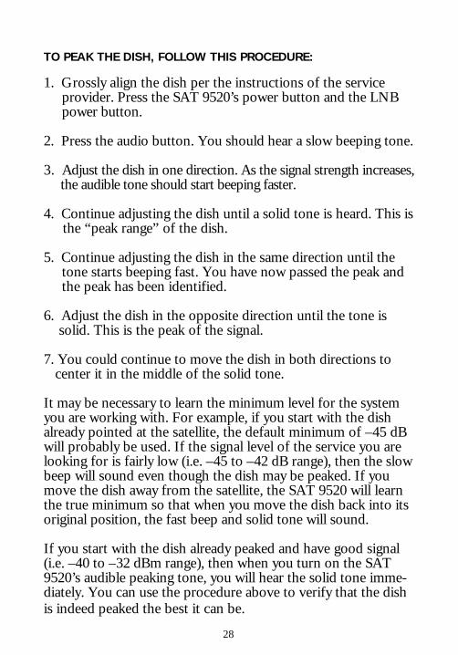
TO PEAK THE DISH, FOLLOW THIS PROCEDURE:
1. Grossly align the dish per the instructions of the service provider. Press the SAT 9520’s power button and the LNB power button.
2. Press the audio button. You should hear a slow beeping tone.
3. Adjust the dish in one direction. As the signal strength increases, the audible tone should start beeping faster.
4. Continue adjusting the dish until a solid tone is heard. This is the “peak range” of the dish.
5. Continue adjusting the dish in the same direction until the tone starts beeping fast. You have now passed the peak and the peak has been identified.
6. Adjust the dish in the opposite direction until the tone is solid. This is the peak of the signal.
7. You could continue to move the dish in both directions to center it in the middle of the solid tone.
It may be necessary to learn the minimum level for the systemyou are working with. For example, if you start with the dishalready pointed at the satellite, the default minimum of –45 dBwill probably be used. If the signal level of the service you arelooking for is fairly low (i.e. –45 to –42 dB range), then the slowbeep will sound even though the dish may be peaked. If youmove the dish away from the satellite, the SAT 9520 will learnthe true minimum so that when you move the dish back into itsoriginal position, the fast beep and solid tone will sound.
If you start with the dish already peaked and have good signal(i.e. –40 to –32 dBm range), then when you turn on the SAT9520’s audible peaking tone, you will hear the solid tone imme-diately. You can use the procedure above to verify that the dishis indeed peaked the best it can be.

29
AUDIBLE C/N PEAKING FEATUREThe Audible C/N Peaking feature enables the user to makepolarity adjustments to horizontal/vertical polarity LNBs anduses the same tone-beeping pattern as the level peaking func-tion.
TO USE THE AUDIBLE C/N PEAKING FEATURE:
1. Peak the level first by adjusting the azimuth and elevation to obtain the best signal strength.
2. Press the speaker button to activate the audible peaking tone. A speaker icon will flash next to the signal level reading to indicate that the Level Peaking mode is active.
3. Press the F1 button to switch to the C/N mode. The flashing speaker icon will appear next to the C/N reading to indicate the measurement being peaked.
4. Adjust the polarity of the LNB to obtain the solid peaking tone and maximize the C/N.
NOTE: YOU WILL HEAR THE SLOW BEEP UNTIL MORE THAN 4 DB OF C/NIS OBTAINED. THE SOLID TONE WILL SOUND WHEN THE C/N ISWITHIN 0.4 DB OF THE HIGHEST PEAK DETECTED SINCE THE RUNBUTTON WAS PRESSED OR SINCE A LOCK WAS OBTAINED.
FREQUENCY DEVIATION ESTIMATEThis measurement checks the frequency error in the LNB or instacking up-converters. Because the accuracy of this estimate isnot specified, it should be used as an indicator only. This mea-surement is not meaningful unless a signal lock has been ob-tained.
The Frequency Deviation Estimate will be displayed in place ofthe BER on the lower right part of the display. Press F2 from

30
the Run Mode to toggle between the BER and the FrequencyDeviation Estimate. This number indicates the frequency offset(in kHz) between the observed signal and the frequency definedin the channel plan.
EXAMPLE:
If you are tuned to transponder 1 at 974 MHz, and the deviationreported is –1500 kHz, the signal frequency from the LNB is972.5 MHz (974 MHz – 1500 kHz = 972.5 MHz). This mightindicate a 1.5 MHz error in the LNB’s local oscillator. Thismagnitude would probably not be noticeable on a clear day, butwould reduce the rain fade margin substantially.
NOTE: THE SAT 9520 IS CONFIGURED TO LOCK ON TO SIGNALS WITH UP TO A 3.5 MHZ OFFSET AND THE SET-TOP IRD MAY LOCK AT EVEN GREATER OFFSETS DURING STRONG SIGNAL CONDITIONS.
POST-FEC BIT ERROR RATEThe Post-FEC BER test measures the bit error rate (BER) afterforward error correction (FEC) is applied. This is a final mea-surement of the quality of the delivered picture and the onlymeasurement that is relevant to the viewer. If there are noerrors in the decoded signal, the picture is perfect regardless ofthe quality of the signal before decoding.
The SAT 9520 also provides a BER figure before error correc-tion and an intermediate BER between the two FEC stages.These measurements indicate the quality of the received signaland let you assess how close your system comes to havingproblems that will be noticeable to the viewer.
To perform a Post-FEC BER on the selected channel, press[F1]. The following screen is then displayed:

31
This test will continue to count errors and update the rate aslong as the transponder remains locked.
The Pre-FEC error count shows the errors found in the previousblock of 2.5 Mbits. The Pre-FEC BER is the same rate asdisplayed on the normal run screen.
The corrected error count shows the number of errors thatsurvived the Viterbi decoding but were caught by the Reed-Solomon decode. If this BER exceeds 1.0E-4, the RS decodewill begin to fail, causing the signal quality “cliff effect”.
The Post-FEC BER is the rate of errors that the RS decode wasunable to correct over the duration of the test. Normally, thiscount will be zero and the Post-FEC BER will decrease as thelength of time increases. A BER of 1.0E-12 or less is consid-ered perfect, while a BER of 1.0E-6 or more is considerednoticeable.

32
Scan Mode searches through all transponders, collecting criticalparameter information. When finished, summary information isdisplayed in several screens. Use Scan Mode to verify that yoursystem operates correctly at all frequencies.
TO START A SCANFirst, be sure that the correct channel plan is selected for yoursystem and that the LNB power is turned on if needed. If youare using a multi-switch, press the LNB button until the desiredswitch setting is obtained. Then, press the [SCAN] button.
While scanning, the following screen is displayed:
The bar graph shows the progress through the channels andreadings for each transponder are shown briefly.
SUMMARY SCREENSWhen the scan is completed, the following screens display thesummary information, with left and right hand polarity transpon-ders summarized separately. Press the [UP] and [DOWN]buttons to scroll between these screens.
SCAN MODE

33
The Found Transponders screen shows the transponders used inthe scan summary that matched the desired system type(DIRECTV or DVB-S).
The Power Summary screen shows the maximum and minimumpower levels for both left hand and right hand polarity transpon-ders. It also shows the difference between the maximum andminimum, which indicates the tilt across the entire frequencyrange.
The Bit Error Rate summary screen shows the maximum andminimum BER for left and right polarity transponders. This isthe PRE-FEC BER and does not include channels for which alock could not be obtained.

34
The C/N summary screen will be titled with whichever qualitymeasurement you have selected in Setup Mode: C/N, Eb/N0 orEs/N0. It also shows the maximum and minimum of themeasurements for left and right polarity channels.
The Adjacent Channel Power Difference screen shows the worstcase comparisons of adjacent channel power readings. It doesthis for the left and right polarity channels separately and alsocompares adjacent channels across polarity, unless a stackedchannel plan is selected. The display shows the two channelswith the worst case difference in power and indicates what thatdifference is.
NOISE SCAN CHANNEL PLANThe “Noise Scan” channel plan may be used with an RF noisesource to sweep a cable system and check for suck-outs or highfrequency roll-off. A broadband noise generator such as theApplied Instruments NS-1 is convenient for this use.

35
The “Noise Scan” channel plan uses the same frequencies as the“Single 1000” to allow a scan over the entire 950 to 2150 MHzrange. All channels are defined as “(DC-2)” or Digicipher IIchannels, which simply tells the SAT 9520 that a code lock isnot needed.
When using the scan function with this channel plan and a noisesource, the only summary screen that contains meaningful datais the Power Summary screen. This screen will show the maxi-mum and minimum power levels for the odd numbered channels(950-1500 MHz) and for the even numbered channels (1500-2150 MHz). This provides an easy check of the cable systemacross the frequency ranges.

36
POLARITYThe satellites transmit polarized signals that overlap in fre-quency. There are two types: circular and planar. Circularpolarization has left-hand or right-hand circular polarizedsignals, while planar polarization has vertical or horizontalpolarized signals. This scheme allows opposite polarity channelsto overlap in frequency without interfering.
On most satellites, the odd numbered transponders use right-hand or vertical polarity and the even numbered transpondersuse left-hand or horizontal polarity. However, there are excep-tions to this rule.
DUAL POLARITY LNBS“Interleaved” systems leave the transponders in the samerelative frequency positions as transmitted from the satellite.Because the opposite polarity transponders overlap in frequency,only one set can be selected at a time for transmission on thecable from the antenna. In dual polarity LNBs, this selection ismade using 18 or 13 volts DC on the cable center conductor.Most channel plans are set up for dual polarity LNBs and therecommended voltage is part of the channel plan definition.Therefore, the SAT 9520 automatically sets the proper voltagewhen the LNB power is on and a channel is selected.
In a “stacked” system, the left-hand or horizontal polaritytransponders are shifted in frequency and “stacked” on top ofthe right-hand or vertical polarity frequencies. The unshifted
POLARITY AND MULTIPLE LNBS

37
transponders are at the same frequency as those in inter-leaved systems, but the shifted transponders are moved tofrequencies between 1450 and 2150 MHz. Both can bepresent on the distribution cable at the same time. This isuseful in multiple dwelling unit applications.
SINGLE POLARITY LNBSSome systems use an LNB that supports only a single polarityand must be mechanically positioned to configure the systemfor horizontal or vertical transponders. To simplify operationwith this type of LNB, several channel plans are providedthat contain only transponders from one polarity or the other.For example, “C-Band H” contains only horizontal transpon-ders while “C-Band V” contains only vertical transponders.When installing one of these systems, you should select aplan that matches the polarity your system will use.
MULTIPLE LNB ANTENNASOval antenna dishes that can receive signals from satellites attwo or more orbital positions are also available. Theseantennas have one LNB for each orbital slot and either aninternal or an external switch to select a satellite. The LNBbutton can be pressed repeatedly to rotate through the avail-able switch positions, provided the switch type is set up asdescribed below. Some channel plans have an associatedswitch type.
MULTI SWITCHESWhen using a switch, you can toggle between LNBs (switchsettings) by pressing the LNB button on the SAT 9520.

38
EXAMPLE:
You are using a DiSEqC™ switch with a Dual 500 service oninput 1, a Single 1000 service on input 2, and a Dish 500service on input 3. You would like the SAT 9520 to measure theSingle 1000 service through the DiSEqC™ switch. Connect allof the dishes to the switch according to the instructions pro-vided with the switch. Connect the SAT 9520 to one of theoutput ports on the switch. Turn on the SAT 9520 and selectthe channel plan for Single 1000. Then, under SWITCH TYPEselect “DiSEqC.” Press [RUN] on the SAT 9520. Press the LNBbutton until the lower left part of the display reads “Dish 2”(press LNB button twice). You can now use the SAT 9520 onthe Single 1000 feed.
ANOTHER EXAMPLE:
You are using a DishPro™ system with the twin LNB head thathas an internal switch. Select the “DishPro” channel plan, theswitch type changes to “DiSEqC.” While this switch type wouldwork with the external DishPro™ switch, it will not work withthe twin head. So, change the switch type to “DpTwin.” Now,when you press the LNB button once, the LNB 1 for the 110°satellite will be selected. Press the LNB button a second time toselect LNB 2 for the 119° satellite.

39
The signal locking capability enables the SAT 9520 to identifywhich satellite a signal is coming from and to obtain BERmeasurements. There are three standard formats for digitalsignals in use: DVB-S, DIRECTV™ and DigicipherII™ (DC2).The SAT 9520 can lock onto DVB-S and DIRECTV™, but notDC2.
For DVB-S and DIRECTV™ signals, the SAT 9520 will display“Search” in the lock indicator position while searching for a lockand “DVB-S,” “DIRECTV,” or a system specific label when alock is obtained. Examples of system specific labels are“DIRECWY” (for Hughes DIRECWAY™ signals),“STARBAND” and “TACHYON.”
The SAT 9520 cannot lock onto DC2 signals so “(DC2)” isdisplayed instead of “Search.” Because it cannot lock onto DC2signals, it cannot provide a BER measurement for these chan-nels. However, it can measure signal level and provide anestimated C/N.
The signal MUST be locked in order to obtain a BER reading.Also, if the signal is not locked, the C/N will be less stable andaccurate. This will, in turn, compromise the Eb/N0, Es/N0,and IRD readings. Until the signal is locked, the demodulatorscans for a frequency and clock rate that will produce a validsignal. The frequency deviation estimate will vary substantiallydue to the frequency scan.
SIGNAL LOCKING
40
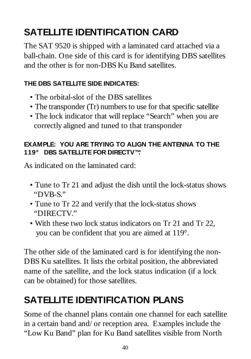
SATELLITE IDENTIFICATION CARDThe SAT 9520 is shipped with a laminated card attached via aball-chain. One side of this card is for identifying DBS satellitesand the other is for non-DBS Ku Band satellites.
THE DBS SATELLITE SIDE INDICATES:
• The orbital-slot of the DBS satellites• The transponder (Tr) numbers to use for that specific satellite• The lock indicator that will replace “Search” when you are correctly aligned and tuned to that transponder
EXAMPLE: YOU ARE TRYING TO ALIGN THE ANTENNA TO THE119° DBS SATELLITE FOR DIRECTV™.
As indicated on the laminated card:
• Tune to Tr 21 and adjust the dish until the lock-status shows “DVB-S.”• Tune to Tr 22 and verify that the lock-status shows “DIRECTV.”• With these two lock status indicators on Tr 21 and Tr 22, you can be confident that you are aimed at 119°.
The other side of the laminated card is for identifying the non-DBS Ku satellites. It lists the orbital position, the abbreviatedname of the satellite, and the lock status indication (if a lockcan be obtained) for those satellites.
SATELLITE IDENTIFICATION PLANSSome of the channel plans contain one channel for each satellitein a certain band and/or reception area. Examples include the“Low Ku Band” plan for Ku Band satellites visible from North

41
America and the “C-Band H” plan for C Band satellites usingthe horizontal polarity setting on the LNB.
With this type of plan, the channel label in the upper left cornerof the screen indicates the orbital position and satellite designa-tion that the channel is set up to receive. If you receive a lock-status other than “Search” or “(DC2)” for one of these chan-nels, you are locked onto the indicated satellite.
For more information, refer to the application note “Lower KuSatellite Identification.”

42
The standard Nickel-Cadmium battery pack will last for 300 to1000 charge-discharge cycles, if properly cared for. ChargingNi-Cad batteries more often than necessary will shorten theirlife, so it is best to wait until the battery status indicator readsempty before recharging the battery.
The SAT 9520 has a fast battery charge circuit that charges thebattery to 85 percent capacity in approximately 2 hours. Anovernight charge (6 to 8 hours) will continue charging until thebattery is completely full.
LEAVING THE CHARGER ON AFTER THE BATTERY IS COMPLETELYCHARGED WILL NOT HARM THE UNIT, BUT REMOVING THECHARGER AFTER 6 TO 8 HOURS IS RECOMMENDED.
BATTERY STATUS INDICATORThe battery indicator symbol on the LCD display shows therelative battery charge status:
When the “Empty” symbol is shown, the unit should be re-charged. If the charge falls too far below the empty mark, theunit will automatically shut off to avoid damage to the battery.
BATTERY CHARGING
!
Full Partial Empty

43
BATTERY CHARGE LEDThe battery charge LED shows the status of the battery charg-ing circuit:
Off Charger is not connectedYellow Fast chargingGreen Battery nearly full and in a trickle-charge mode
WALL TRANSFORMERThe wall transformer is rated at 120 VAC, 50-60Hz input and 24VAC at 1.5 Amperes output with 2.1 mm plug. Using a trans-former with a lesser or greater rating may damage the trans-former and the SAT 9520.
ANY ATTEMPTS TO CHARGE THE BATTERY WITH AN EXTERNALPOWER SOURCE OTHER THAN THE PROVIDED AC WALLTRANSFORMER MAY RESULT IN POOR OPERATION OR DAMAGE TOTHE UNIT.WARNING
!

44
Digital signals are significantly different from the traditionalanalog signals. The following diagram illustrates what a digitalsignal looks like on a spectrum analyzer and shows the two mostbasic measurements: the signal power level and the carrier-to-noise ratio (C/N).
Measuring the signal level is useful when aligning the antennaand adjusting amplifiers. In general, a stronger signal is betterunless it overdrives the amplifiers or receivers. The C/N ratioprovides a measurement of the signal quality. The larger thisdifference, the fewer errors received.
Unfortunately, some types of signal impairments that affectperformance can remain hidden within the digital “haystack.”These impairments will not show up in the C/N ratio; however,they will show up in a Bit Error Rate (BER) measurement.
DIGITAL SIGNAL MEASUREMENTS

45
The classic BER measurement is performed either by transmit-ting a known bit pattern and comparing it to the received bitpattern, or by comparing transmitted and received bit patternsdirectly. The former requires a disruption of service, and thelatter is not possible except at a satellite uplink facility.
Furthermore, because DBS systems use forward error correction(FEC), the BER measurement will remain very good until theimpairments become so insurmountable that the FEC is unableto make the corrections. This is known as the “cliff effect.”
The diagram below illustrates how the digital channels maintainnearly perfect picture quality with increasing level of impair-ment until the “cliff” has been reached. At that point, the signalwill quickly degrade to no picture at all. Although analogchannels will maintain some picture even after digital channelsquit all together, customers become unhappy with analog fuzzand snow long before digital channels fail to provide a picture.

46
BIT ERROR RATEThe SAT 9520 utilizes data from the FEC process to providemore useful BER measurements without requiring a disruptionof service. There are two types: a Pre-FEC BER and a Post-FEC BER.
The Pre-FEC BER test is based on the number of errors de-tected by the first stage of the FEC process, the Viterbi decoder.This BER is measured quickly and provides an estimation ofavailable margin. Because it measures errors found in the rawreceived signal, not the corrected signal, it indicates the damagecaused by interference and noise, thereby showing the effect ofthe impairments hidden within the digital “haystack” and lettingyou assess how close to the “cliff” you are.
A Post-FEC BER measurement is also available in the SAT9520. This uses data from the second stage of the FEC process,the Reed-Solomon decoder, to measure the errors that survivedthe first stage and the errors that remain in the final signal that isdelivered to the customer. An intermediate stage error rate isalso displayed as part of the Post-FEC BER test.
A Post-FEC BER of 1E-6 is considered a threshold for visibledegradation1 and a “perfect” signal has been defined as one thathas a BER of 1E-12 or less. A BER of 1E-12 is less than onebit wrong out of 1 trillion bits. Unfortunately, it takes about 9hours to receive 1 trillion bits, so it would take 9 hours to testfor a BER of 1E-12. To obtain any statistical level of confi-dence, you would need to allow even more time! This level oftesting is probably not something you want to do in the field,but the SAT 9520’s Post-FEC BER test will run as long as youwish and will display the number and BER of corrected anduncorrected errors for the duration of its running time.1THOMAS & EDGINGTON, DIGITAL BASICS FOR TELEVISION, PRENTICEHALL, 1999.

47
EB/N0DEFINITION: EB/N0 = ENERGY-PER-BIT / NOISE-PER-HZ
Eb/N0 can be thought of as the average carrier-to-noise ratioper bit. It can be used to compare the performance of differentmodulation systems without having to correct for different bitrates.
The carrier-to-noise ratio (C/N) and Eb/N0 are related by thefollowing formula:
+ 10log(noiseBandwidth)-10log(bitrate)
where bit rate is in bits per secondnoiseBandwidth is in Hertz (24 MHz for DBS signals)
The bit rate refers to the bits received after the bits added forthe FEC process have been removed. The standard DBS signalsuse a 20 MHz symbol rate, with 2 bits per symbol. The FECprocess adds bits for Reed Solomon and Viterbi encoding. A130/147 Reed Solomon code rate and a 6/7 Viterbi code rateproduce an overall code rate factor of 0.758. The bit rate isthus:
bit rate = 40 MBps * 0.758 = 30.3 MBps
+ 10log(24MHz)-10log(30.3MHz)
– 1.01
EbN0=
CN
EbN0=
CN
EbN0= C
N

48
ES/N0DEFINITION: ES/N0 = ENERGY PER SYMBOL / NOISE PER HZ
The Carrier to Noise ratio (C/N) can be converted to Es/N0with the following formula:
+10log(noiseBandwidth)-10log(symbolRate)
In this case, the symbol rate for DBS signals is always 20 MHz,so:
+ 10log(24) – 10log(20)
+ 0.79
These formulas are dependent upon the symbol rate and thenoise bandwidth. The noise bandwidth depends on the symbolrate and the filtering coefficient. These numbers are part of thetuner setup parameters associated with each channel. The SAT9520 will automatically use the correct values for the channelwhen a signal lock has been obtained. The bit rate is alsodependent on the Viterbi code rate. The SAT 9520 scans theavailable code rates in the process of obtaining signal lock andthe matching code rate is used in the bit rate computation.
EsN0=
CN
EsN0=
CN
EsN0=
CN
49
The following list shows the “Standard” North American plansavailable at the time of this printing. For the latest list ofavailable channel plans see www.appliedin.com.
DBS PLANS:These plans are for use with the DBS systems.
Dual 500 For standard DIRECTV™ “interleaved”systems, tunable to 32 transponder frequenciesfrom 950 to 1450 MHz (101°, 110°, 119°).
Single 1000 For DIRECTV™ stacked LNB systems thatmove the even transponders to 1500 thru 2025MHz, 32 transponder frequencies.
Bell Express For “interleaved” Bell ExpressVu™ systems (32frequencies from 950 to 1450 MHz).
Bell Stacked For Bell ExpressVu™ systems using the NASstacking up-converter (32 frequencies from 950to 2150 MHz).
Dish 500 For Echostar/Dish Network™ single or twinsystems (950 to 1450 MHz).
DishPro For Echostar/Dish Network™ stacked systemsthat look at multiple satellites (61°, 110°, 119°).
CHANNEL PLANS

50
KU BAND SATELLITES:These plans are each configured for a particular satellite andcontain the digital transponders which the SAT 9520 can lockonto or measure.
Galaxy 4R For use with WSNet™, “HITS”, and Hughes.
G4R Stacked Galaxy 4R with a stacked LNB system.
GE4 @101W For AMC4 (formerly GE4) transpondersincluding STARBAND™ Internet signals.
SatMex 5 SM5 individual transponder frequencies.
Telstar 5 T5 individual transponder frequencies.
Telstar 6 T6 individual transponder frequencies forWSNet™ program signals using an“interleaved” LNB (950 to 1450 MHz).
Telstar 6Stacked T6 individual transponder frequencies for
WSNet™ program signals using a stacked LNB(950 to 2150 MHz).
Telstar 7 T7 individual transponder frequencies.
SATELLITE ID PLANS:These plans are configured with one channel per satellite andcover a range of satellites for a particular band or LNB configu-ration.

51
Low Ku Band For identifying Ku satellites using an“interleaved” dual polarity LNB. (LO =10.750 GHz).
Low Ku Stacked Same as above but using a stacked LNB(950 to 2150 MHz).
Starband H Primarily for installing STARBAND™satellite Internet systems that have ahorizontal polarity transmitter (verticalreceive).
Starband V Primarily for installing STARBAND™satellite Internet systems that have avertical polarity transmitter (horizontalreceive).
C-Band H/V For identifying C-Band satellites on systemsthat utilize dual polarity LNBs downconverted to 950-1450 MHz.
C-Band H For locating C-Band satellites on systemsset for horizontal polarity.
C-Band V For locating C-Band satellites on systemsset for vertical polarity.
SPECIAL PURPOSE PLANS:
Noise Scan For use with a noise source for cablesweeping. See additional informationlabeled “NOISE SCAN CHANNELPLAN” in the SCAN MODE section.

52
WSNet Dual For use with the WSNet™ dual LNB systemwith interleaved LNBs. (950 to 1450 MHz).Contains G4R and T6 channels.
WSNet Stack Same as above but for stacked LNBs (950 to2150 MHz).

53
FREQUENCY CHART