coyote in-line runt closure, hermetically...
TRANSCRIPT

COYOTE® In-Line RUNT Closure, Hermetically SealedBe sure to read and completely understand this procedure before applying product. Be sure to select the proper PREFORMED product before application.
NOMENCLATURE: 1. Coverwithairvalveholeplug 2. Basewithorganizer 3. Endplatecablecap(2) 4. Endplatecapbolt(6) 5. Disposableglove 6. Hingeplug(2) 7. Tie-downclip(4)
8. CableGrommets(4) 9. Screw-onterminallug(2)10. Siliconelubricant(4-fivegrampks)11. Organizerstud(2)12. Trayhold-downstrap(2)13. Hoseclamp(4)14. 12-ctsplicetray(soldseparately)
TOOLS REQUIRED:• 3/8”&7/16”Canwrenchorsocket• 1/4”Nutdriverorscrewdriver• Snips• Fiberopticcableopeningtools
1
2
3
4
5
6
7
8
9
10
11
12
13
14
(Soldseparately)
Capacities
Splice Tray Catalog No.
DescriptionSplices per
trayTrays for Closure Splice capacity
80807701LowProfile
SingleFusion 12 4 48
80806033Standard
SingleFusionorMechanical
12 2 24
80808945LITE-GRIP®
SingleFusion(FullBlockSet)
40 2 80
LGSTR144LITE-GRIP®
Ribbon72 2 144
COYOTE In-Line RUNT Closure KitsCatalog Number Description
8006951 COYOTEIn-LineRUNTClosureKit,HermeticallySealed8006952 COYOTEIn-LineRUNTClosureKit,FreeBreathing80061004 COYOTEIn-LineRUNTExpressHermeticallySealed80061049 COYOTEIn-LineRUNT,FlameRetardant
NOVEMBER 2010

2
COYOTE In-Line RUNT AccessoriesCatalog Number Description
Splice Tray Kits80807701 12-CountLowProfileSpliceTraywithplasticspliceblock-singlefusion80806033 12-CountStandardSpliceTraywithelastomericspliceblock-singlefusion&mechanical80807114 72CountRibbonSpliceTraywithelastomericspliceblock-massfusion80807769 BlankLowProfileSpliceTray-nospliceblock
Miscellaneous Accessory Kits8003733 EndPlateKit-includes(1)endplate,(3)fasteners,(1)siliconepack80807794 HardwareBagKit8003713 ExpressBracketKit-includes(4)expressbrackets8003719 COYOTEIn-LineRUNTCoverKit
80805293 TransportTubeKit.135”ID:includes(6)34”longtransporttubes-forsinglefibers80806439 TransportTubeKit.25”ID:includes(6)34”longtransporttubes-forribbonorsinglefibers80807989 TransportTube100’reel0.170”ID-forribbonorsinglefibers80807991 TransportTube100’reel0.25”ID-forribbonorsinglefibers
Mounting Hardware Kits8003703 Pole/WallMountBracketKitforIn-LineRUNTandTerminalClosure(singleordualchamber)8003704
AerialHangingBracketKitforCOYOTEIn-LineRUNTandTerminalClosure(singlechamber)80037978003706 SwingArmBracketforCOYOTEIn-LineRUNTandTerminalClosures(singleordualchamber)8003714 PedestalMountingBracket-forIn-LineRUNTandTerminalClosure,EmersonPR012pedestalonly
COYOTE Grommet ChartFor use in COYOTE Dome, In-Line RUNT, Taut & Terminal Closures
PLP Catalog Number Cable Range Inches (mm) Description Splitting Location
8003701 .42-.85(11-22mm) 2-entrygrommet
8003691 .42-.60(11-15mm) 1-entrygrommet
8003692 .60-.85(15-22mm) 1-entrygrommet
8003693 .85-1.0(22-25mm) 1-entrygrommet
8003694 1.0-1.25(25-32mm) 1-entrygrommet
8003663 .42-.60(11-15mm) 2-entrygrommet
8003664 .30-.43(8-11mm) 4-entrygrommet
8003990.50 - .60 (12.7 - 15.2) .125 - .25 (3.2 - 6.4)
and flat drop4-entrygrommet
8003989 Flat Drop Only 4-entrygrommet
8003665 .125-.25(3-6mm) 6-entrygrommet
8003676.42-.60(11-15mm).125-.25(3-6mm)
7-entrygrommet
8003677 .125-.25(3-6mm) 8-entrygrommet
NOTE:GrommetKitcontains(1)Grommet,(1)CableMeasureTape,(2)SiliconeLubricantPacks,(1)SetofPlugs&(1)Glove
3
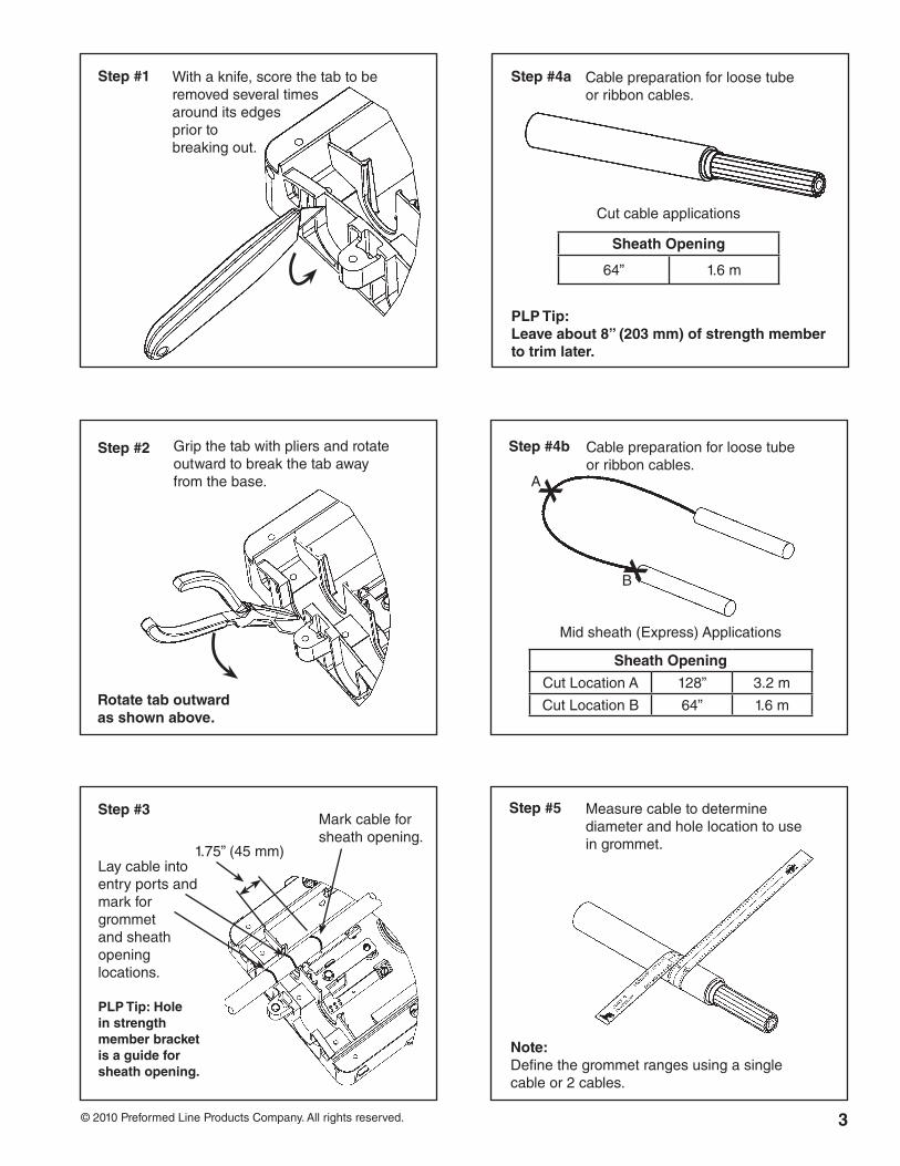
Gripthetabwithpliersandrotateoutwardtobreakthetabawayfromthebase.
©2010PreformedLineProductsCompany.Allrightsreserved.
Step #1
Step #3
Withaknife,scorethetabtoberemovedseveraltimesarounditsedgespriortobreakingout.
Rotate tab outward as shown above.
Step #5
Step #2
Laycableintoentryportsandmarkforgrommetandsheathopeninglocations.
PLP Tip: Hole in strength member bracket is a guide for sheath opening.
1.75”(45mm)
Markcableforsheathopening.
Step #4a Cablepreparationforloosetubeorribboncables.
Sheath Opening
64” 1.6m
Cutcableapplications
Measurecabletodeterminediameterandholelocationtouseingrommet.
Note: Definethegrommetrangesusingasinglecableor2cables.
Step #4b Cablepreparationforloosetubeorribboncables.
Sheath Opening
CutLocationA 128” 3.2m
CutLocationB 64” 1.6m
A
X
XB
PLP Tip:Leave about 8” (203 mm) of strength member to trim later.
Midsheath(Express)Applications
4
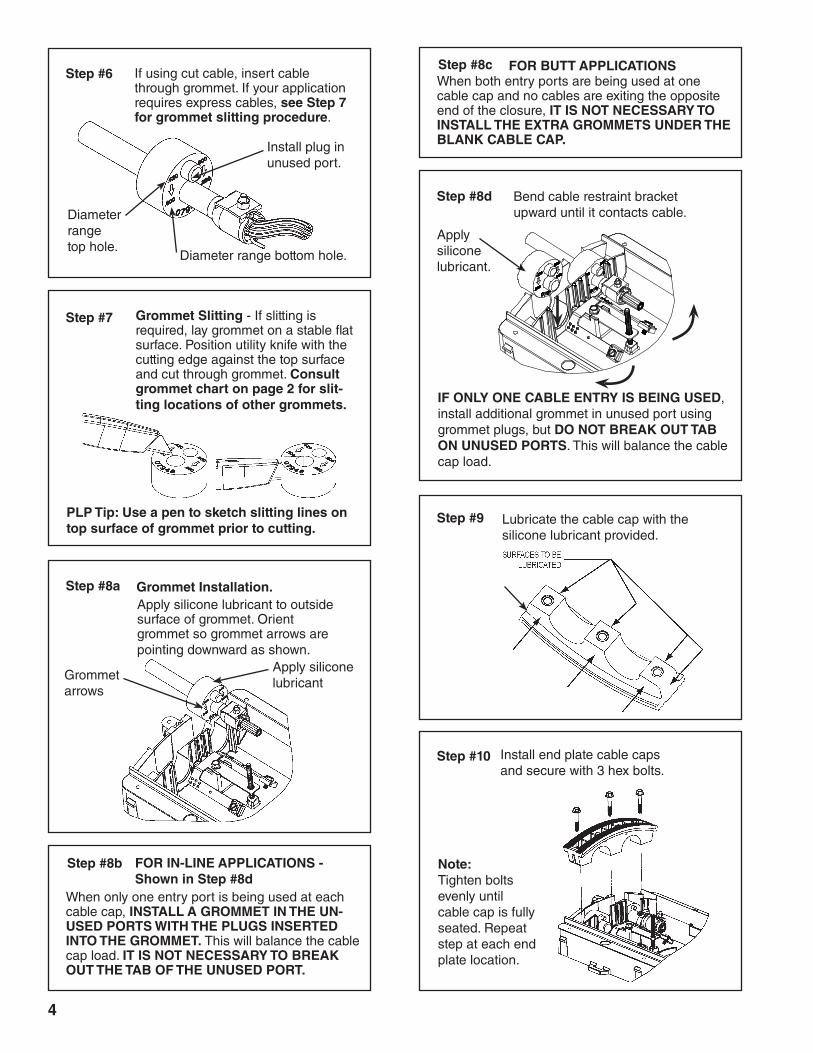
Step #9 Lubricatethecablecapwiththesiliconelubricantprovided.
Installendplatecablecapsandsecurewith3hexbolts.
Note: Tightenboltsevenlyuntilcablecapisfullyseated.Repeatstepateachendplatelocation.
Step #10
Step #8a Grommet Installation.
Step #8d
Applysiliconelubricanttooutsidesurfaceofgrommet.Orientgrommetsogrommetarrowsarepointingdownwardasshown.
Step #7 Grommet Slitting-Ifslittingisrequired,laygrommetonastableflatsurface.Positionutilityknifewiththecuttingedgeagainstthetopsurfaceandcutthroughgrommet.Consult grommet chart on page 2 for slit-ting locations of other grommets.
PLP Tip: Use a pen to sketch slitting lines on top surface of grommet prior to cutting.
Bendcablerestraintbracketupwarduntilitcontactscable.
Applysiliconelubricant
Grommetarrows
Ifusingcutcable,insertcablethroughgrommet.Ifyourapplicationrequiresexpresscables,see Step 7 for grommet slitting procedure.
Step #6
Installpluginunusedport.
Diameterrangetophole.
Diameterrangebottomhole.
Applysiliconelubricant.
IF ONLY ONE CABLE ENTRY IS BEING USED,installadditionalgrommetinunusedportusinggrommetplugs,butDO NOT BREAK OUT TAB ON UNUSED PORTS.Thiswillbalancethecablecapload.
Step #8b FOR IN-LINE APPLICATIONS - Shown in Step #8d
Whenonlyoneentryportisbeingusedateachcablecap, INSTALL A GROMMET IN THE UN-USED PORTS WITH THE PLUGS INSERTED INTO THE GROMMET.Thiswillbalancethecablecapload.IT IS NOT NECESSARY TO BREAK OUT THE TAB OF THE UNUSED PORT.
Step #8c FOR BUTT APPLICATIONSWhenbothentryportsarebeingusedatonecablecapandnocablesareexitingtheoppositeendoftheclosure, IT IS NOT NECESSARY TO INSTALL THE EXTRA GROMMETS UNDER THE BLANK CABLE CAP.

5
Step #11
PLP Tip: If ground isolation is required, wrap 2 layers of vinyl tape around the strength member and cable prior to installing the hose clamp.
Securecablesheathwithhoseclamp.Repeatforallcables.
Step #13
Step #14
Ifrequired,puncturesurfaceofgroundwireholeinendplatecablecapandinsert#6solid,jacketedgroundwire.
Installscrew-onterminallugonendofgroundwireandattachtoshieldconnector.
Step #12Step #15
Note: Applysiliconelubricanttosurfaceofgroundwiretoeaseinsertionintoendplate.
Step #16
Installorganizerstudsandtiedownclips.(Isometric)
TrayStrapOrganizerStud
Measureandmarkthebuffertube.
41”(66mm)fromcableopening
Applybluefeltstrip
Openandcleanfiberperyouracceptedcompanypractice.
Routebuffertubesorribbonfibertobesplicedoncearoundthestorageareatoonecorner.
In-Line Application
Butt Application
SecurestrengthmemberandKEVLAR®belowcap.
6
Step #19
PLP Tip: Install tie wraps in splice tray before placing them on the threaded studs.
Step #20
Step #22
Step #21 Securesplicetray(s)withhold-downstraps.
Routeincomingcablefibersatleast1-1/2timesaroundsplicetrayandintospliceblock.
Routeoutgoingcablefibersatleast1-1/2timesaroundsplicetrayandintospliceblock.
Securethebuffertubesortransporttubingwithtiewraps.
Splicefiberspercompanypractices.
Step #18 Installsplicetrayonthreadedstuds.
Applysiliconelubricatetocoversurfacesbeforeinstalling.
Applysiliconelubricant.
Outgoingcablefiber
Incomingcablefiber
Step #17
7
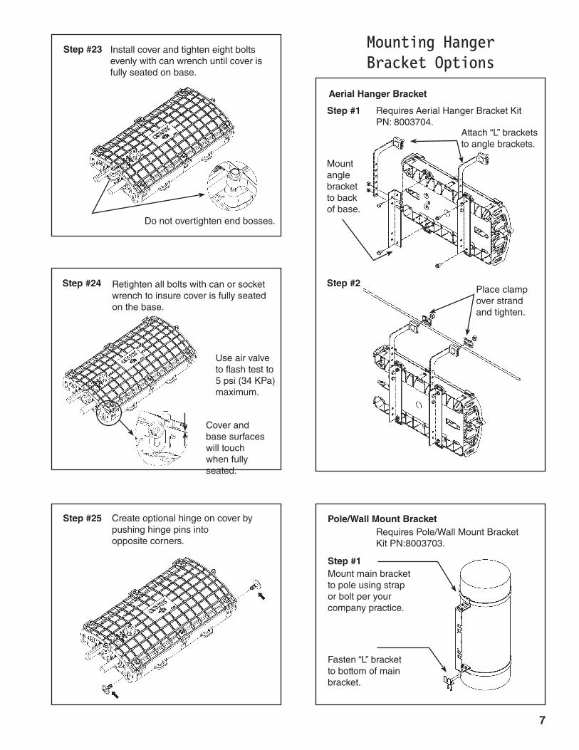
Step #25 Createoptionalhingeoncoverbypushinghingepinsintooppositecorners.
Retightenallboltswithcanorsocketwrenchtoinsurecoverisfullyseatedonthebase.
Useairvalvetoflashtestto5psi(34KPa)maximum.
Step #1 RequiresAerialHangerBracketKitPN:8003704.
Step #23
Coverandbasesurfaceswilltouchwhenfullyseated.
Mounting Hanger Bracket Options
Aerial Hanger Bracket
Step #2
Attach“L”bracketstoanglebrackets.
Mountanglebrackettobackofbase.
Placeclampoverstrandandtighten.
Step #1
RequiresPole/WallMountBracketKitPN:8003703.
Pole/Wall Mount Bracket
Mountmainbrackettopoleusingstraporboltperyourcompanypractice.
Fasten“L”brackettobottomofmainbracket.
Donotovertightenendbosses.
Installcoverandtighteneightboltsevenlywithcanwrenchuntilcoverisfullyseatedonbase.
Step #24
8
P.O.Box91129,Cleveland,Ohio44101•440.461.5200•www.preformed.com•e-mail:[email protected]
SP2962-7
SAFETY CONSIDERATIONS
Thisapplicationprocedureisnotintendedtosupersedeanycompanyconstructionorsafetystandards.Thisprocedure isofferedonlytoillustratesafeapplicationfortheindividual.FAILURE TO FOLLOW THESE PROCEDURES MAY RESULT IN PERSONAL INjURY OR DEATH.
Do not modify this product under any circumstances.
Thisproductisintendedforusebytrainedtechniciansonly.This product should not be used by anyone who is not familiar with, and not trained to use it.
Whenworkingintheareaofenergizedlines,extracareshouldbetakentopreventaccidentalelectricalcontact.
Forproperperformanceandpersonalsafety,besuretoselectthepropersizePREFORMED™productbeforeapplication.
PREFORMEDproductsareprecisiondevices.Toinsureproperperformance,theyshouldbestoredincartonsunder coverandhandledcarefully.
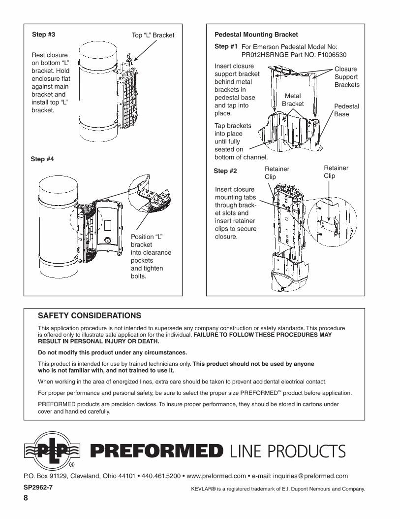
Step #4
Position“L”bracketintoclearancepocketsandtightenbolts.
Step #3
Restclosureonbottom“L”bracket.Holdenclosureflatagainstmainbracketandinstalltop“L”bracket.
Top“L”Bracket
Step #1
Pedestal Mounting Bracket
ForEmersonPedestalModelNo:PR012HSRNGEPartNO:F1006530
MetalBracket
ClosureSupportBrackets
PedestalBase
Insertclosuresupportbracketbehindmetalbracketsinpedestalbaseandtapintoplace.
Tapbracketsintoplaceuntilfullyseatedonbottomofchannel.
Step #2
Insertclosuremountingtabsthroughbrack-etslotsandinsertretainerclipstosecureclosure.
RetainerClip
RetainerClip
KEVLAR®isaregisteredtrademarkofE.I.DupontNemoursandCompany.