cpe installation procedure v2
TRANSCRIPT

7/27/2019 CPE Installation Procedure V2
http://slidepdf.com/reader/full/cpe-installation-procedure-v2 1/17
CPE Installation Document
Contents
1. Packaging Contents
2. IP Plan and RF Plan
3. Verification of exact POE
4. Physical Verification of Power Source
5. Physical Installation Procedure
6. Grounding Rules
7. Connectivity Procedures for SS
8. AT Trial Deployment recommendations
9. Configurations in SS
10. Provisioning Check of SS in EMS
11. RF Connectivity Check
12. Basic commands to check the connectivity through CLI interface
13. Procedure for throughput test
7/27/2019 CPE Installation Procedure V2
http://slidepdf.com/reader/full/cpe-installation-procedure-v2 2/17
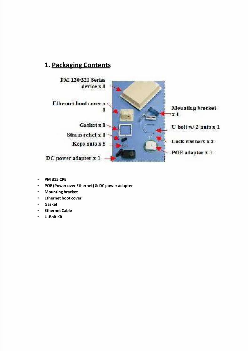
1. Packaging Contents
• PM 315 CPE
• POE (Power over Ethernet) & DC power adapter
• Mounting bracket
• Ethernet boot cover
• Gasket
• Ethernet Cable
• U-Bolt Kit

7/27/2019 CPE Installation Procedure V2
http://slidepdf.com/reader/full/cpe-installation-procedure-v2 3/17
2. IP Plan and RF PlanIP Address:
Subnet Mask:
Default Gateway:
Channel Bandwidth: 5MHz or 10MHz
Channel Frequency: As per frequency configured in BS
3. Verification of exact POE for SS
RED GREEN

7/27/2019 CPE Installation Procedure V2
http://slidepdf.com/reader/full/cpe-installation-procedure-v2 4/17
4. Physical Verification of Power SourceCheck for the stable Power Source where the Power Adaptor for the POE would be connected
Ideal Power Source: 230V AC
5. Physical Installation Procedure
Mounting of Brackets and Ethernet Cable Installation Steps

7/27/2019 CPE Installation Procedure V2
http://slidepdf.com/reader/full/cpe-installation-procedure-v2 5/17
Pole Mounting
• Position the clamp around the pole (1 - 3 in) in the desired location
• Install and tighten the clamp bolts enough to secure the clamp to the pole.
• Tighten these screws only after antenna pointing.
Pin-outs for Ethernet Cable
Verification of the Ethernet Cable using Cable Tester

7/27/2019 CPE Installation Procedure V2
http://slidepdf.com/reader/full/cpe-installation-procedure-v2 6/17
6. Grounding Rules
Proper Grounding is a most essential part of the installation process. Grounding on Base Station isdone at Outdoor unit and the POE
Properly Grounded Radio: A grounded radio causes the surge to pass directly to ground
bypassing the radio
• Locate the grounding lug on the CPE at the back panel of the outdoor unit
• Provide a proper grounding conductor long enough to reach from the Outdoor Unit to the
earth ground
• Crimp one end of a grounding cable to the suitable cable lug
Similarly for Grounded POE: In this case the surge will be picked up by the Cat5 cable and since
the POE is grounded the route for the surge is through the POE to ground
Grounding Lug
If incase Grounding Point is not available the same needs to be communicated to the user as this
could cause damage to the port connecting to the POE. Also ensure the installer puts some proper
insulation tape on the grounding LUG

7/27/2019 CPE Installation Procedure V2
http://slidepdf.com/reader/full/cpe-installation-procedure-v2 7/17
7. Connectivity Procedures for SS
PC Marked Connect to
PC or SwitchCPE Labeled to be
connected to ODU
Power Adaptor
Earthing LUG
7/27/2019 CPE Installation Procedure V2
http://slidepdf.com/reader/full/cpe-installation-procedure-v2 8/17
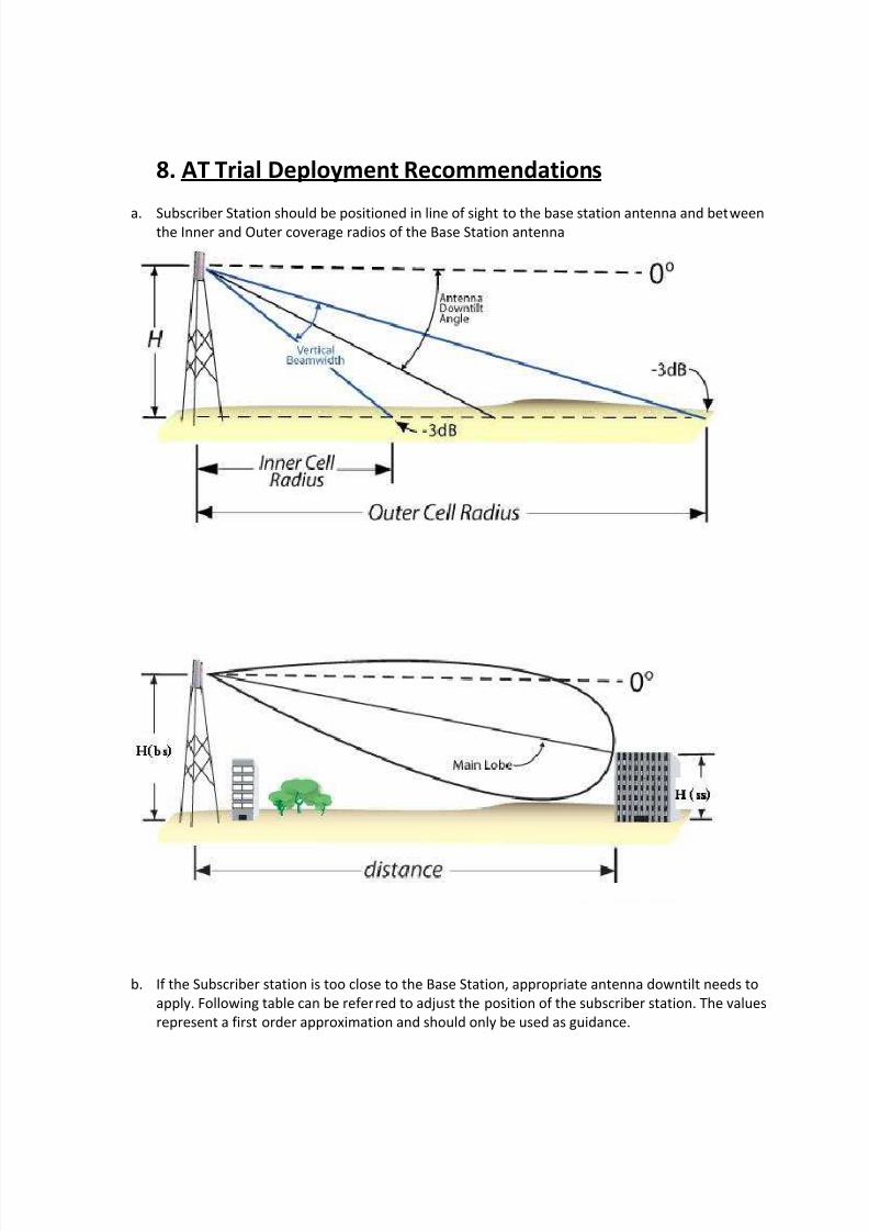
8. AT Trial Deployment Recommendations
a. Subscriber Station should be positioned in line of sight to the base station antenna and betweenthe Inner and Outer coverage radios of the Base Station antenna
b. If the Subscriber station is too close to the Base Station, appropriate antenna downtilt needs to
apply. Following table can be referred to adjust the position of the subscriber station. The values
represent a first order approximation and should only be used as guidance.

7/27/2019 CPE Installation Procedure V2
http://slidepdf.com/reader/full/cpe-installation-procedure-v2 9/17
Antenna Height
(Mtrs) SS Distance BSA Down tilt
BS SS (mtrs) (Deg)
10 1 25 21
20 1 25 38
30 1 25 50
40 1 25 58
10 1 50 10
20 1 50 21
30 1 50 30
40 1 50 37
10 1 100 5
20 1 100 10
30 1 100 16
40 1 100 21
10 1 200 2
20 1 200 5
30 1 200 8
40 1 200 10
c. Subscriber station should be pole mounted on a permanent fixture so that the subscriber stationantenna direction does not change due to wind or external factors.
d. It is recommended not to carry a subscriber station in hand during establishing a link or during
recording critical AT data.

7/27/2019 CPE Installation Procedure V2
http://slidepdf.com/reader/full/cpe-installation-procedure-v2 10/17
9. Configurations in SS
SS Installation Procedure through WebGui
Log in to the Configurator
Your Subscriber Unit provides a Web-based Configuration for performing advanced
configuration activities. After you install your Subscriber Unit, use the following procedure to
launch the Configuration.
1. Use an Ethernet cable to connect the Ethernet port labeled PC on the PoE adapter to a
network-interface card (NIC) in a PC or network hub. Then connect the other Ethernet port
on the PoE adapter to the Subscriber Unit.
2. Start your Web browser and point it to one of the following default IP addresses:
http://192.168.0.1. The Login page in Figure 3 appears, with your cursor in the User name
field.
3. Enter the default username admin and default case-sensitive password default in the
appropriate fields.
4. Click the OK button to log in. The Information Page appears. This read-only page displays
network, wireless and device information about your installation.
IP Address 192.168.0.55
Subnet Mask 255.255.255.0
Gateway Not Required
X - O v e r

7/27/2019 CPE Installation Procedure V2
http://slidepdf.com/reader/full/cpe-installation-procedure-v2 11/17
Specify Wireless SettingsAfter logging in to the Configuration, use the following procedure to set the Subscriber
Unit’s wireless settings.
• In the left pane, under WiMAX Setup, click Wireless. The Wireless Settings page
appears.• Set the three groups of parameters as indicated in Table below. These values must
match the ones you entered for the Pico Base Station.
• Click the Apply button. A page tells you that your configuration changes have beensaved, but will not be applied until you reboot the Subscriber Unit.
• Do not reboot the Subscriber Unit at this time. Instead, proceed to “Specify Network
Setup Settings”.

7/27/2019 CPE Installation Procedure V2
http://slidepdf.com/reader/full/cpe-installation-procedure-v2 12/17

7/27/2019 CPE Installation Procedure V2
http://slidepdf.com/reader/full/cpe-installation-procedure-v2 13/17
Link Status
should be
Operational
Management VLAN=10
Data VLAN =100

7/27/2019 CPE Installation Procedure V2
http://slidepdf.com/reader/full/cpe-installation-procedure-v2 14/17
10. Provisioning Check of SS in EMS
SS needs to be provisioned in the EMS by the NOC team. After the discovery of the SS in the Airsync EMSand after successful registration of SS in the EMS SS would be able to communicate with the Backhaul
Network
11. RF Connectivity Check
SS has the LED Support to check the Link Status
RSSI≤
-96dBm 1
-95dBm ≤ RSSI -86 dBm 2
-85dBm ≤ RSSI ≤ -76 dBm 3
-75dBm ≤ RSSI ≤ -61 dBm 4
ON = Connection to LAN established
BLINKING = Connection in use
OFF= No LAN Connection
LAN
ON = Connection to BS Established
OFF= No Connection to BS
Radio
ON = CPE is fully operational
BLINKING = CPE is booting or shutting
down
Status
7/27/2019 CPE Installation Procedure V2
http://slidepdf.com/reader/full/cpe-installation-procedure-v2 15/17
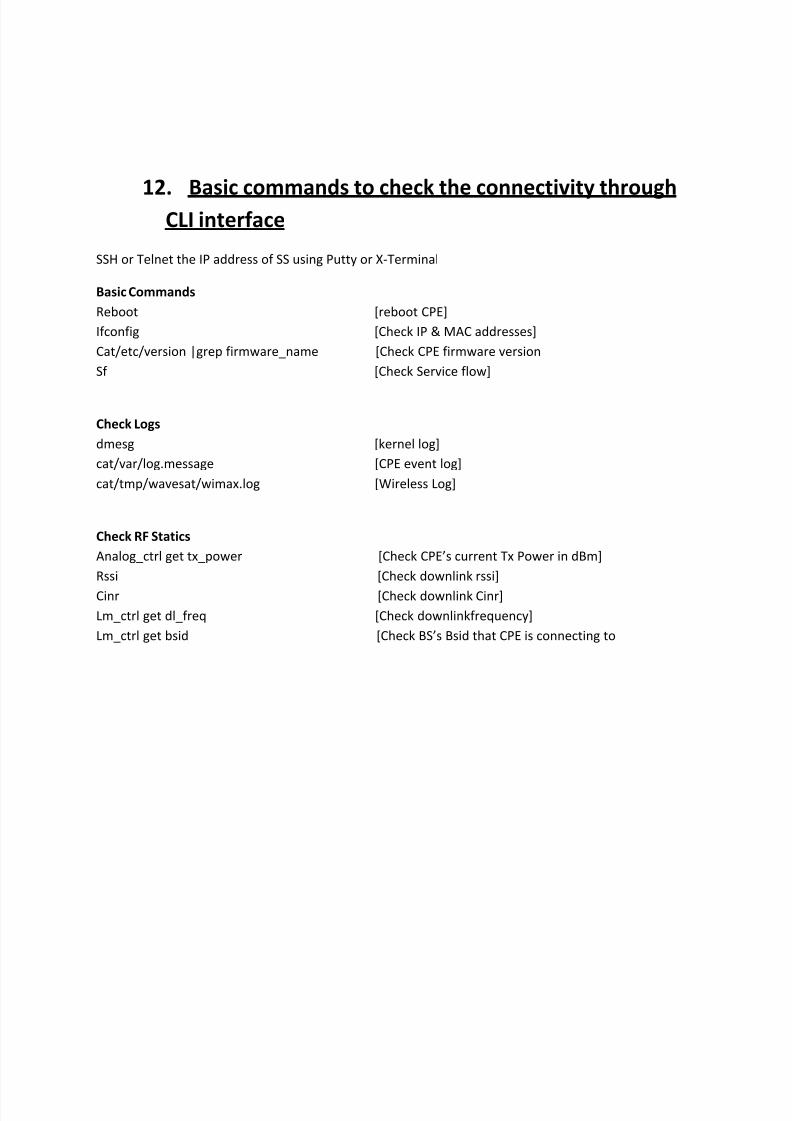
12. Basic commands to check the connectivity throughCLI interface
SSH or Telnet the IP address of SS using Putty or X-Terminal
Basic Commands
Reboot [reboot CPE]
Ifconfig [Check IP & MAC addresses]
Cat/etc/version |grep firmware_name [Check CPE firmware version
Sf [Check Service flow]
Check Logs
dmesg [kernel log]
cat/var/log.message [CPE event log]
cat/tmp/wavesat/wimax.log [Wireless Log]
Check RF Statics
Analog_ctrl get tx_power [Check CPE’s current Tx Power in dBm]
Rssi [Check downlink rssi]
Cinr [Check downlink Cinr]
Lm_ctrl get dl_freq [Check downlinkfrequency]
Lm_ctrl get bsid [Check BS’s Bsid that CPE is connecting to

7/27/2019 CPE Installation Procedure V2
http://slidepdf.com/reader/full/cpe-installation-procedure-v2 16/17
13. Procedure for throughput test
JPERF can be downloaded from the Software FTP Site. Install JPerf on both the
PC. Connect one PC behind the Base-Station and other behind the CPE. First do the
connectivity check between this PC and then run Server on PC behind BS and Jperf
Client on the PC connected to CPE.

7/27/2019 CPE Installation Procedure V2
http://slidepdf.com/reader/full/cpe-installation-procedure-v2 17/17
IP Address of PC running
Jperf Server