cps contactless power systemshyuedun.com/upfile/20122239332673499.pdf · questionnaire 11 cps ......
TRANSCRIPT

CPS®
CONTACTLESSPOWER SYSTEM
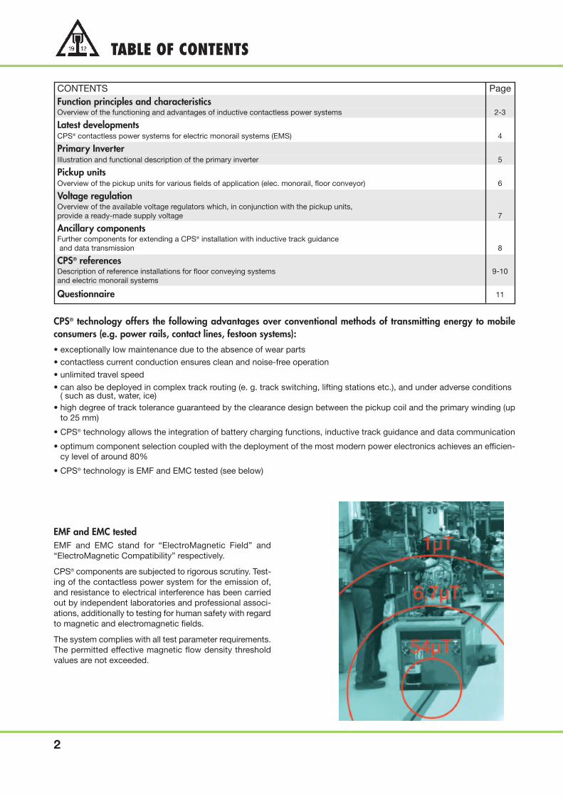
TABLE OF CONTENTS
2
CONTENTS PageFunction principles and characteristicsOverview of the functioning and advantages of inductive contactless power systems 2-3
Latest developmentsCPS® contactless power systems for electric monorail systems (EMS) 4
Primary InverterIllustration and functional description of the primary inverter 5
Pickup unitsOverview of the pickup units for various fields of application (elec. monorail, floor conveyor) 6
Voltage regulationOverview of the available voltage regulators which, in conjunction with the pickup units, provide a ready-made supply voltage 7
Ancillary componentsFurther components for extending a CPS® installation with inductive track guidanceand data transmission 8
CPS® referencesDescription of reference installations for floor conveying systems 9-10and electric monorail systems
Questionnaire 11
CPS® technology offers the following advantages over conventional methods of transmitting energy to mobile consumers (e.g. power rails, contact lines, festoon systems):• exceptionally low maintenance due to the absence of wear parts
• contactless current conduction ensures clean and noise-free operation
• unlimited travel speed
• can also be deployed in complex track routing (e. g. track switching, lifting stations etc.), and under adverse conditions( such as dust, water, ice)
• high degree of track tolerance guaranteed by the clearance design between the pickup coil and the primary winding (upto 25 mm)
• CPS® technology allows the integration of battery charging functions, inductive track guidance and data communication
• optimum component selection coupled with the deployment of the most modern power electronics achieves an efficien-cy level of around 80%
• CPS® technology is EMF and EMC tested (see below)
EMF and EMC testedEMF and EMC stand for “ElectroMagnetic Field” and“ElectroMagnetic Compatibility” respectively.
CPS® components are subjected to rigorous scrutiny. Test-ing of the contactless power system for the emission of,and resistance to electrical interference has been carriedout by independent laboratories and professional associ-ations, additionally to testing for human safety with regardto magnetic and electromagnetic fields.
The system complies with all test parameter requirements.The permitted effective magnetic flow density thresholdvalues are not exceeded.
FUNCTION PRINCIPLES
3
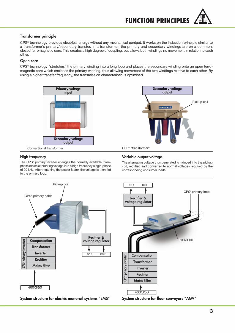
Transformer principleCPS® technology provides electrical energy without any mechanical contact. It works on the induction principle similar toa transformer’s primary/secondary transfer. In a transformer, the primary and secondary windings are on a common,closed ferromagnetic core. This creates a high degree of coupling, but allows both windings no movement in relation to eachother.
Open coreCPS® technology “stretches” the primary winding into a long loop and places the secondary winding onto an open ferro-magnetic core which encloses the primary winding, thus allowing movement of the two windings relative to each other. Byusing a higher transfer frequency, the transmission characteristic is optimised.
Primary voltageinput
Secondary voltageoutput
Conventional transformer
Secondary voltageoutput
Pickup coil
High frequencyThe CPS® primary inverter changes the normally available three-phase mains alternating voltage into a high frequency single-phaseof 20 kHz. After matching the power factor, the voltage is then fedto the primary loop.
System structure for electric monorail systems ”EMS”
Rectifier &voltage regulatorCompensation
Transformer
Inverter
Rectifier
Mains filter
400/3/50
CPS® primary cable
Pickup coil
DC 1 DC 2
Variable output voltageThe alternating voltage thus generated is induced into the pickupcoil, rectified and converted to normal voltages required by thecorresponding consumer loads.
System structure for floor conveyors “AGV”400/3/50
CPS® primary loop
Pickup coil
DC 1 DC 2
Compensation
Transformer
Inverter
Rectifier
Mains filter
Rectifier &voltage regulator
CPS® ”transformer“
CPS®
prim
aryi
nver
ter
CPS®
prim
aryi
nver
ter

CPS® contactless power system for electric monorail systems ”EMS”
CPS® technology has meanwhile also been successfully deployed in electric monorail applications. By complete-ly eliminating contact dependant components, e.g. sliding contacts, maintenance work and the consequentrunning costs to the user can be significantly reduced.
The modular design of the mobile components of the CPS® equipment enables, as with the AGV sector, a widespan of power ranges to be covered easily using the U-form pickup units. Even the compact 0.7 kW pickup unittype PS 15 has a built in voltage regulator which provides a user-friendly supply voltage of 560 V DC in addi-tion to an auxiliary voltage of 24 V DC for the control supply.
Along with inductive energy transmission, integrated data transmission is of course also available whererequired, as well as a position encoding system (see page 8 for description)
Special characteristics:
• Compliance with the VDI-C1 guidelines
• Simple and precise conductor installation in monorail profiles with clip-on holders
• Inductive supply (i.e. no cable chains) to track switches and lifters within the track routing is also available.
• Strict compliance with EMF threshold values by utilizing two-conductor technology and low primary current
• Smallest possible horizontal curve radius: 750 mm
• Smallest possible vertical curve radius: 1,500 mm
LATEST DEVELOPMENTS
4
Data antenna
U-form pickup
Advantages over conventional technology:
• 100% maintenance-free, therefore maximumplant utilization
• No carbon abrasion, therefore no work piececontamination
• Unlimited travel speed
• No noise development
• Integrated data transmission
PRIMARY INVERTER
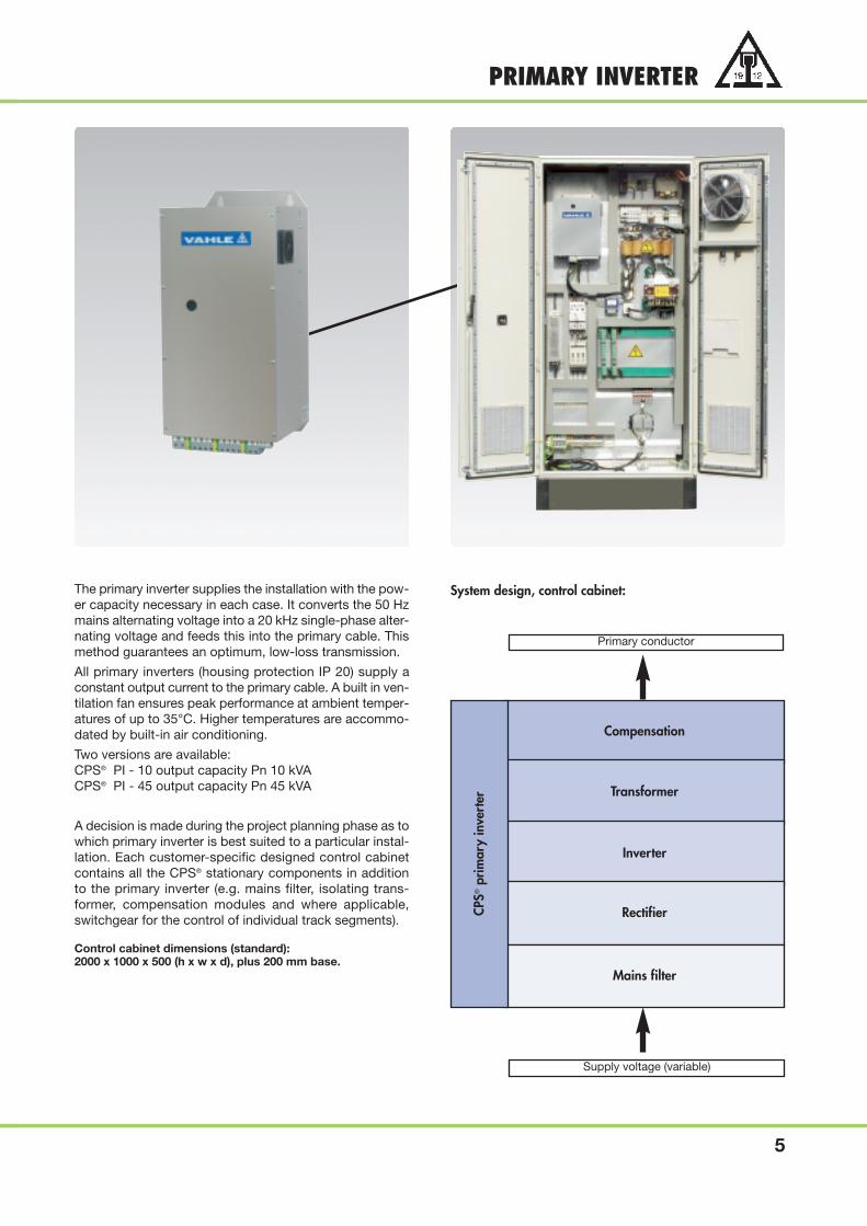
The primary inverter supplies the installation with the pow-er capacity necessary in each case. It converts the 50 Hzmains alternating voltage into a 20 kHz single-phase alter-nating voltage and feeds this into the primary cable. Thismethod guarantees an optimum, low-loss transmission.
All primary inverters (housing protection IP 20) supply aconstant output current to the primary cable. A built in ven-tilation fan ensures peak performance at ambient temper-atures of up to 35°C. Higher temperatures are accommo-dated by built-in air conditioning.
Two versions are available:CPS® PI - 10 output capacity Pn 10 kVACPS® PI - 45 output capacity Pn 45 kVA
A decision is made during the project planning phase as towhich primary inverter is best suited to a particular instal-lation. Each customer-specific designed control cabinetcontains all the CPS® stationary components in additionto the primary inverter (e.g. mains filter, isolating trans-former, compensation modules and where applicable,switchgear for the control of individual track segments).
Control cabinet dimensions (standard):2000 x 1000 x 500 (h x w x d), plus 200 mm base.
System design, control cabinet:
5
Compensation
Transformer
Inverter
Rectifier
Mains filter
CPS®
prim
ary
inve
rter
Supply voltage (variable)
Primary conductor

6
PICKUP SYSTEMS(1)
The pickup unit is responsible for the inductive pick-up of energy from the primary cable. Various types of pickupsare available for this purpose, dependant on application.
Flat designType pickup CPS® PS 08 with integrated voltage regulator
PU 07 with separate voltage regulator (page 7)PU 09 with separate voltage regulator (page 7)
U-form designType pickup CPS® PS 15 with integrated voltage regulator
E-form designType pickup CPS® PU 22 with separate voltage regulator (page 7)
This pickup unit with it’s flat design is conceived for use inautomated guided vehicle systems (AGV), and for skidconveyor applications.
With their robust housing design and resistance to shortcircuits and overloads, the reliability of CPS® componentsguarantee the highest level of plant utilization.
Available output capacities:0.5 kW / 24 V DC0.5 kW with battery charging management1.5 kW3.0 kW
(higher capacities are available by using parallel switching)
The U-form design of this pickup unit with its integratedvoltage regulator is conceived for applications in the elec-tric monorail sector.
The twin conductor system developed by VAHLE specifical-ly for this application, has proven it’s capability especiallywith regard to it’s excellent EMF and EMC behavior.
Available output capacity:750 W/560 V DC + 24 V DC auxiliary voltage
The E-form design of this pickup unit is conceived for useinmaterial handling applications with an increased capac-ity requirement.
With their robust housing design and resistance to shortcircuits and overloads, the reliability of CPS® componentsguarantee the highest level of plant utilization.
Available output capacity:24 kW
(higher capacities are available by using parallel switching)
(1) Detailed product information on request
7
VOLTAGE REGULATOR(1)
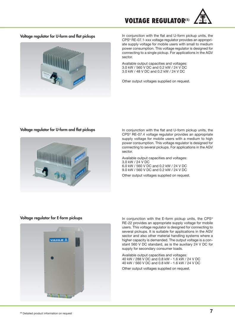
In conjunction with the flat and U-form pickup units, theCPS® RE-07.1-xxx voltage regulator provides an appropri-ate supply voltage for mobile users with small to mediumpower consumption. This voltage regulator is designed forconnecting to a single pickup. For applications in the AGVsector.
Available output capacities and voltages:3.0 kW / 560 V DC and 0.2 kW / 24 V DC3.0 kW / 48 V DC and 0.2 kW / 24 V DC
Other output voltages supplied on request.
In conjunction with the flat and U-form pickup units, theCPS® RE-07.4 voltage regulator provides an appropriatesupply voltage for mobile users with a medium to highpower consumption. This voltage regulator is designed forconnecting to several pickups. For applications in the AGVsector.
Available output capacities and voltages:3.0 kW / 24 V DC6.0 kW / 560 V DC and 0.2 kW / 24 V DC9.0 kW / 560 V DC and 0.2 kW / 24 V DC
Other output voltages supplied on request.
In conjunction with the E-form pickup units, the CPS®
RE-22 provides an appropriate supply voltage for mobileusers. This voltage regulator is designed for connecting toseveral pickups. It is suitable for applications in the AGVsector and also other material handling systems where ahigher capacity is demanded. The output voltage is a con-stant 560 V DC standard, as is the auxiliary 24 V DC forsupply for secondary consumer loads.
Available output capacities and voltages:40 kW / 288 V DC and 0.8 kW - 1.6 kW / 24 V DC40 kW / 560 V DC and 0.8 kW - 1.6 kW / 24 V DC
Other output voltages supplied on request.
(1) Detailed product information on request
Voltage regulator for U-form and flat pickups
Voltage regulator for U-form and flat pickups
Voltage regulator for E-form pickups

Track guidance sensor
Data transmission
ANCILLARY COMPONENTS(1)
8
The track guidance sensor CPS® SS-01 detects the mag-netic field of the CPS® primary cable, thus enabling reli-able inductive vehicle guidance.
The VAHLE track guidance sensor is perfectly matched tothe physical characteristics of the CPS® primary conduc-tor. An additional cable for inductive guidance is no longernecessary.
Data transmission using the VAHLE Powercom CPS®
enables faultless communication to all connected mobileparticipants.
In addition to the 20 kHz used for energy transmission, a carrier frequency is coupled into the CPS® primary cableto provide fail-safe FSK modulated data signal transmis-sion.
The CPS® primary cable is used for the transmission. Inother words, an additional cable for data transmission isnot necessary.
The VAHLE Powercom® CPS® rounds off the CPS® productrange.
A reliable data interface is available for e.g. Profibus DPand other 2-wire bus systems with an 11 bit protocol anda data rate of up to 19.2 Kbit/s for AGV and elec. monorailsystems.
The advantages of this contactless track guidance system are obvious. The supply of electricity and the track guidance are“one system”; there is no mechanical wear, the floors are even and offer no obstacles to cross traffic.Apart from this, the system guarantees the highest level of plant utilisation and is suitable for track switching and crossinglayouts.
If these VAHLE data transmission products are used, additional data transmission systems can be dispensed with complete-ly. They are simply integrated into the CPS® energy supply system. No design changes to the CPS® track installation are nec-essary.
Absolute measurement processing
Contactless
Immune to power failure
No reference points
Accuracy = 0.8 mm
Speed up to 12 m/s
Variable track length up to 325 m
Suitable for curved tracks
Maintenance friendly
(1) Detailed product information on request

9
CPS® REFERENCES CPS® for automated guided vehicle systems (AGV)
Characteristics:• high level of plant utilization
through maintenance-freeenergy supply
• shock hazard protection
• unlimited accessibility of theAGV track system
• variable, vehicles are de-ployed to match the produc-tion process
• no noise development
• no influence on functionalsafety from floor contami-nation
CPS® with inductive data transmission, VAHLE Powercom® CPS®:In the assembly line of BMW AG’s Munich works, in February 2000, a 285 m long assembly track was commissioned.It ranged over two floors on which, in the 1st construction phase, 49 AGVs, which conveyed the car engines between thework places, travelled over a lifting station, a crossing, several track switches and four switchable track sections to providea smooth flow of materials. In the second construction phase during 2003/2004, the track was extended by 81 m with additional 9 vehicles in order to integrate the gearbox mounting into the production process. Further to this, on the upperfloor, another assembly line with 14 AGVs was commissioned on which, after further process steps, the engine together withthe gearbox and axle are transferred to an electric monorail system (EMS).Based on Profibus DP, the transmission of energy and data to all 72 vehicles, takes place completely contact-free through theCPS® system.A unique feature of the floor conveying system is the emergency stop switch-off capability for individual track segments bymeans of an appropriate CPS® concept.
CPS® with contactless track guidance:In October 2001, in the SML/Ford works in Genk, Belgium,an automated guided vehicle system was commissioned.Over a total track length of 148 m, 23 AGVs transport carengines to the individual work stations.Here contactless energy supply is operating with the aid ofVAHLE CPS® technology. The on board AGV battery ismerely for servicing and allows the vehicle to be movedunder electrical power away from the CPS® supplied track.CPS® technology is also used here for the track guidance.An inductive track guidance sensor built into the vehicledetects the magnetic field of the primary cable laid in thefloor and provides an analog signal for the steering.

10
CPS® REFERENCESCPS® for electric monorail systems (EMS)
Characteristics:• high level of plant utilization and correspondingly low
upkeep costs due to considerable freedom from main-tenance
• unlimited travel speed and acceleration of the mobileusers
• no noise development and no carbon abrasion due tothe completely contact-free transmission of energy
• high track tolerance due to the specific design of theclearance between pickup coil and primary cable
• unlimited deployment even under adverse environmentalconditions such as dust, ice, wind etc.
• high level of efficiency due to optimum componentselection and utilization of the most modern perform-ance electronics
• simple installation of the CPS® components usingclip-on conductor holders in the powerail compacthangers
• in combination with the Stahltronic position encodingsystem WCS, VAHLE offers a complete contactless sys-tem solution for energy, data transmission and position en-coding for the electric monorail sector
CPS® for electric monorail systems (EMS)In Madison, a suburb of Jackson, the state capital ofMississippi in the USA, Tower Automotive Inc. have a pro-duction unit which supplies to the automobile manufacturerNissan. Among other things, the chassis for the so-calledSUV’s (Sport Utility Vehicles) are produced here, which aresubsequently further processed by Nissan at the Cantonworks about 3 miles north of Madison.
The EMS carriers are equipped with regulated 0.6 kW VFD(variable frequences drive) motors and an Allen BradleyPLC to control the carriers. The decoupling of the neces-sary power from the CPS® primary cable is done with theaid of two pickup units from the series CPS® PU 13 with anominal capacity of 650 W each.
A particular challenge for the VAHLE CPS® technology wasthe level of the intermediate circuit voltage for the vehicledrive. In this case, the secondary electronics of the CPS®
RE-07 module, because of the normal 480 V 3-phase powersupply network in the USA, provides a constant output volt-age of 680 V DC for the drive and an auxiliary voltage of 24 VDC for the control supply.
Technical data
Number of tracks: 2 Supply voltage carriers: 680 V DC & 24 V DC (250 W)
Track length: 176 m each Installed CPS® capacity: 45 kW primary inverter per track
Carriers per track: 17 CPS® track equipment: Round conductor 25 mm2 in monorail profile
Carriers nominal capacity: 650 W each Pickup design: 2 x 650 W U-form pickups per carrier
Maximum capacity per carrier: 1.5 kW each

Company: Date:
Tel: Fax:
E-Mail: Internet: (URL)
1. Type of application: AGV EMS Skid conveyor Other (please state)
2. Number of tracks:
3. Track length: m, Number of track switches: pcs.
Number of lifts: pcs. No. of switchable track segments:
4. Travel speed: m/s Acceleration: m/s2
5. No. of vehicles / units per track:
6. Max. power requirement per vehicle (Pnom
/Ppeak
):
7. Simultaneity factor for vehicles:
8. Required voltage supply on the vehicle:
9. Drives with frequency inverter: yes no
10. Indoor Outdoor
11. Ambient conditions:
12. Dust / moisture / influence from chemicals etc.:
13. Ambient temperature: °C
14. Inductive data transmission required? yes no
15. Inductive track guidance required? yes no
16. Position encoding system required? yes no
17. Remarks:
Date:
11
QUESTIONNAIRE
Please copy and fill out the questionnaire.

Catalog no.
Copperhead Conductor Systems 1 a
Battery Charging Systems 1 b
Insulated Conductor Systems U 10 2 a
Insulated Conductor Systems U 20 - U 30 - U 40 2 b
Insulated Conductor Systems U 15 - U 25 - U 35 2 c
Aluminum Enclosed Conductor Systems LSV - LSVG 3 a
Powerail Enclosed Conductor Systems KBSL - KSL - KSLT - KSG 4 a
Powerail Enclosed Conductor Systems VKS - VKL 4 b
Powerail Enclosed Conductor Systems MKLD - MKLF - MKLS 4 c
Powerail Enclosed Conductor Systems VKS 10 4 d
Heavy Enclosed Conductor Systems 5
Trolley Wire and Accessories 6
Cable Tenders 7
Cable Carriers for -tracks 8 a
Cable Carriers for Flatform Cables on -beams 8 bF
Cable Carriers for Round Cables on -beams 8 bR
Cable Carriers for -tracks 8 c
Conductor Cables and Fittings 8 L
Spring Operated Cable Reels 9 a
VAHLE POWERCOM® -Data Transmission Systems 9 c
CPS® - Contactless Power Supply 9 d
SMG - Slotted Microwave Guide 9 e
WCS - Position Encoding System 9 f
Motor Powered Cable Reels 10
Catalog no. 9d/E 2004
PAUL VAHLE GMBH & CO. KG • Westicker Str. 52 • D 59174 KAMEN/GERMANY • TEL. (+49) 23 07/70 40Internet: www.vahle.de • E-Mail: [email protected] • FAX (+49) 23 07/70 44 44
0904
•P
rinte
din
Ger
man
y•
DS
•20
00•
11/0
4
DQS certified in accordance with DIN EN ISO 9001:2000OHSAS 18001 (Reg. no. 003140 QM OH)
MANAGEMENTSYSTEM