cpu-400 solid-waste-fired gas turbine devlopment · f. richard wocasek combustion power company ......
TRANSCRIPT

CPU-400 Solid-Waste-Fired Gas Turbine Devlopment
RICHARD A. CHAPMAN u.s. Environmental Protection Agency
National Environmental Research Center
Cincinnati
ABSTRACT
The U.S. Environmental Protection Agency, Office of Research and Development, has been supporting the solidwaste-fired gas turbine development (CPU-400) project at Combustion Power Company, Inc., Menlo Park, California, on a contract basis since 1967. The 70 ton per day pilot plant has been operated to produce electricity. Turbine deposits have prevented long term operation and further development of gas cleaning equipment is being conducted. Discussed here are system and component development and final configurations plus pertinent results of the development program as they apply to this and other solid waste disposal systems that employ fluidized beds and hot gas cleaning equipment.
INTRODUCTION
In 1967, a study was initiated to determine whether aerospace technology could be applied to the solution of the mounting solid waste disposal problem. Of the numerous concepts evaluated, one that offered great potential combusted refuse in a fluidized bed under pressure and then passed the products of combustion through a gas turbine to drive an electrical generator. This combustion power unit, capable of consuming 400 tons per day of solid waste, was designated the CPU-400 System.
A series of key sub scale experiments were conducted showing that solid waste could be combusted in a fluidized bed at 100 psig (7X 10⁵ n/m2 ) and that the combustor was capable of a heat release rate approaching 1 million
•
F. RICHARD WOCASEK Combustion Power Company
Menlo Park, California
Btu/hr/ft3 (9 billion cal/hr/m3). Also, it was demonstrated that an inertial separator would perform effectively with an acceptable pressure drop under CPU-400 conditions of temperature, pressure, and dust loadings.
In early 1970, the development of a 70 ton per day pilot plant was initiated, and today it is undergoing extensive testing. The system and individual components will be discussed.
THE OVERALL SYSTEM
Figure 1 is an artist's conception of the entire pilot plant and Fig. 2 shows the system schematically. Figure 3 • is a photograph of the hot gas system.
In the solid waste processing facility, municipal packer trucks discharge waste onto the floor from which a skip loader pushes it onto two recessed conveyors. The waste is then shredded and air classified prior to pneumatic transport into the storage unit. The heavy, noncombustible portion from the bottom of the air classifier is processed to remove aluminum and ferrous metals. The combustible waste is withdrawn from the storage vessel across a weighing conveyor and fed into two rotary airlock feeder valves which transfer the waste across the pressure interface into the combustor's pneumatic feeding system. The turbine compressor provides pneumatic transport air and combustionjf1uidizing air. The waste is combusted in the 2-ft-deep (60 cm) fluidized bed and then passed through three stages of particle separators before expansion through the gas turbine. The generated power is dissipated in a resistance load bank. A pneumatic
347

•
DUST COLLECTOR
SHREDDED WASTE
STORAGE
FLUIO BED
COMBUSTOR CLASSIFIER
SEPARATOR
: --
SOLID WASTE PROCESSING
LOW 'RESS. BlOWER
FEEDER
�' .'0 . ... . ' . o • •
CONTROL ROOM
'REHEAT [CLIPS[
Oil
I\IOII[� • ...-.J--'---...
SOLID WASTE
715
nulD lEO CCIIUSTOR
t ' , ' "
AIR DlI"P VAlVE
FILTER
,-1-/,,-
EXHAUST .J'o� DUCTS
AIR
FIG.1 CPU-400 PILOT PLANT
1ST STAG[
S[PMATOl
-
I EXMIIST
INERTIAl SEPARATORS
ZND STAG[
RUSTOfiI CClIIUSTOA
•
I
;[IIOAToo
1110 STAG[
ASH OUTLET
--
FIG.2 CPU-400 SYSTEM SCHEMATIC
348
I
C Cc Cc
0 It
-
BAG HOUSE
FILTER
AI. EXHAUST
I I
All

FIG.3 HOT GAS SUBSYSTEM O F CPU-400 PI LOT PLANT
349

system transfers the ash from the particle separators into the sand bin and baghouse filter. lont rol of the entire process is achieved by t he use of a n on-line process control computer and numerous analog controllers. The pilot plant is fully instrumented, and about 100 channels of analog inputs (temperature, pressure, etc.) and ahout 300 channels of discrete inputs (contact closures, etc.) are recorded.
In addition to the pilot plant system, a 2_ft2 (0.2 m2), low-pressure, nuidi7.ed bed combustor with three stages of particle cleaning equipment is available and used for development testing.
The entire system was developed and tested at low pressure prior to integrating the turbine. At the time of turbine integration, the solid waste processing system was enlarged to handle 85 tons per day of municipal waste.
SOLID WASTE PROCESSING/STORAGE SYSTEM
A 2S00-ft2 ( 232 m2) receiving huilding situated on a 5500-ft 2 (511 m2) pad provides tipping area for approximately 85 tons of solid waste per day. A skip loadcr pushes solid waste onto two 4-ft-wide (I.� m) X 37-ftlong (11.3 m) steel-belt inclined conveyors that transfer the material to two vertical axis shredders, one 75 hp (56 kw) and the other 100 hp (75 kw). Belt speeds are manually controlled between 2 and 0 ft/min (0.6 and 1.8 m/min) whereas feed rate is controlled by on/off cycling of the belts through current sensors on the shredder motors. The system throughput is nominally 5 tons per hour. Both shredders eject shredded material onto a common 4-ft wide (1.2 m) X 22-ft-long (6.7 m) inclined conveyor whidl feeds a single air classifier. Rotating, paddle-style load-levelers on the wnveyor maintain a constant volume input to the air classifier.
The sheet-steel, fabricated air classified (5-ft-wide (1.5 m) X 7-ft-high (2.1 m) X I-ft-thick (0.3 m)) is designed to separate the light combustible material from the heavy nonwmhustibles. In operation, air entering the bottom of the unit is drawn up through a zig-zag path where it intercepts and disperses the incoming solid waste. The air classifier typically drops out about 17 percent of the material and about 83 pen;ent nies overhead. All the combustibles are not separated from the noncombustibles; typically, about 15 percent of the light fraction consists of inert material in the form of glass, sand, metal foils. and ash and about 25 percent of the heavy fraction is combustihle. The light material is drawn through a 7600-ft] / min (215 m] /min) material handling hlower and pneumatically transported approximately 275 ft (84 m) through a lo-in-diameter (44 cm) pipe to the storage/ retrieval unit. The entering solid waste is dc-entrained in
350
the storage unit. and the dust-laden air is extracted by two cyclones.
The air classifier heavy product is processed through a series of devices to recover Illetals and glass. First, a magnet removes the ferrous metals for sale to a local foundry. Glass and stone are removed by a revolving screen for on-site usc as an aggregate fill. Aluminum and mixed other nonferrous metals are recovered from the remaining material by two newly developed, dry electromagnetic separators. The aluminum is sold to Alcoa for reuse as can stock, and the mixed metals are sold for foreign export.
The 20-ft-diameter (6 Ill) by 12-ft-high (3.7 m) storage bin has a usable capacity for about 30,000 Ib (13,600 kg) of solid waste, or approximately 3 to 5 hours' supply at present combustor feed rates. Recovery of ma terial is accomplished by four chains of sweep buckets that contact the material at the outside of the pile and sweep it into an outfced conveyor recessed in the noor. Paddle sensors, responsive to combustor demand, control the rate at which the sweeps and outfeed conveyor deliver material to a transfer conveyor. Rotating load levelers on the transfer conveyor ensure a constant depth of material. The feed rate is controlled through variable-speed, electric-drive systems on both the transfer and weighing conveyors, which are responsive to combustor feed demand signals. The speed range capability allows a variation in feed rate from about 35 to 200 Ib/min (16 to 91 kg) at 3.5 Ib/ft3 (56 kg/m3j material density.
Two 30-in.-diameter (76 cm), 13 pocket, stainless steel, rotary airlock valves are fed by a static splitter assembly on the weighing conveyor. Each feeder valve is driven by a 20-hp (15 kw) drive through a jackshaft assembly at a nominal rotational speed of 11 rpm. The volumetric handling capacity of each valve is 36 fe /min (1 m3/min). As the valves turn, empty pockets receive material from the top, rotate through 180 degrees past a sealing wall, and continuously deliver the material into two 6-in.-diameter (15 cm), high-pressure transport lines at the bottom, which deliver the waste to the combustor.
The feeder valves have carbon impregnated, phenolic bearings that require a continuolls now of water for cooling. When used during low-pressure pilot plant testing, problems were experienced with the cooling water flowing between the rotor and sideplates into the lower portion of the valve. The water mixed with the solid waste dust and formed deposits in the valve pockets, in the transition between the valve and the pneumatic transport pipe and between the rotor and sideplates of the valve. This caused either the transition to completely plug or the drive to overload because the rotating resistance in the valve had increased. The problem has not been experienced during
high-pressure testing since the pneumatic transport air from the turbine compressor is about 350 F (180 C) and this, along with the heating jackets on' the valves, evaporates the water before it mixes with the dust. Also. the high-pressure transport air leaking between the rotor and valve body help to keep this area free of dust.
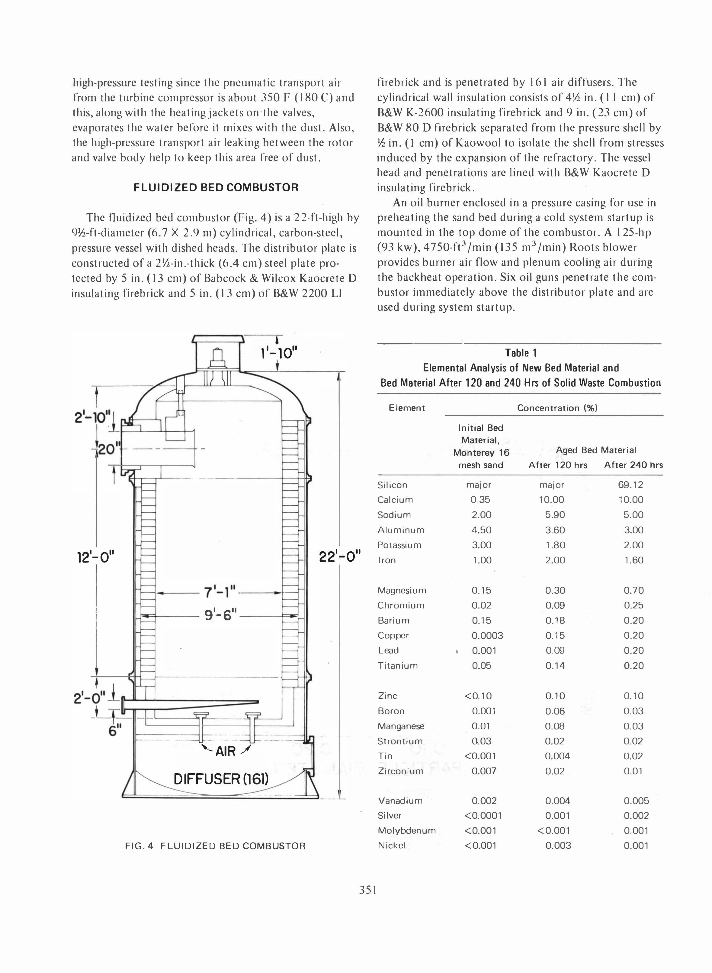
FLUIDIZED BED COMBUSTOR
The Ouidized bed combustor (Fig. 4) is a 2 2-ft-high by 9!h-ft -diameter (6.7 X 2.9 m) cy lind rical, carbon-steel, pressure vessel with dished heads. The distributor plate is constructed of a 2!h-in.-thick (6.4 cm) steel plate protected by 5 in. (i 3 cm) of Babcock & Wilcox Kaocrete D insulating firebrick and 5 in. (13 cm) of B&W 2200 Ll
J 1- -- ---+-, -
- --
.
• 11-10"
121-0" 221-0"
71-1" ---Et �r--- 91- 6" --�:t-
•
I
._- _._-----
• ...!
===-=�_:--::� f-- - - 1--_-=-_"AIR ./
DIFFUSER (161)
FIG.4 FLUIDIZED BED COMBUSTOR
351
firebrick and is penetrated by 161 air diffusers. The cylindrical wall insulation consists of 4!h in. (II cm) of B&W K-2600 insulating firebrick and 9 in. (23 cm) of B&W 80 0 firebrick separated from the pressure shell by !h in. (I cm) of Kaowool to isolate the shell from stresses induced by the expansion of the refractory. The vessel head and penetrations are lined with B&W Kaocrete D insula ling firebrick.
An oil burner enclosed in a pressure casing for use in preheating the sand bed during a cold system startup is mounted in the top dome of the combustor. A l 25-hp (93 kw), 4750-ft 3 /min (135 m3/min) Roots blower provides burner air flow and plenum cooling air during the backheat operation. Six oil guns penetrate the combustor immediately above the distributor plate and are used during system startup .
Table 1 Elemental Analysis of New Bed Material and
Bed Material After 120 and 240 Hrs of Solid Waste Combustion
Element
Si I icon
Calcium
Sodium
Aluminum
Potassium
I ron
Magnesium
Chromium
Barium
Copper
Lead
Titanium
Zinc
Boron
Manganese
Strontium
Tin
Zirconium
Vanadium
Si Iver
Molybdenum
Nickel
Initial Bed
Material,
Monterey 16 mesh sand
major
0 35
2.00
4.50
3.00
1.00
0.15
0.02
0.15
0.0003
, 0.001
0.05
<0.10
0.001
0.01
0.03
<0.001
0.007
0.002
<0.0001
<0.001
<0.001
Concentration (%)
Aged Bed Material
After 120 hrs After 240 hrs
major
10.00
5.90
3.60
1.80
2.00
0.30
0.09
0.18
0.15
0,09
0.14
0.10
0.06
0.08
0.02
0.004
0.02
0.004
0.001
<0.001
0.003
69.12
10.00
5.00
3.00
2.00
1.60
0.70
0.25
0.20
0.20
0.20
0.20
0.10
0.03
0.03
0.02
0.02
0.01
0.005
0.002
0.001
0.001
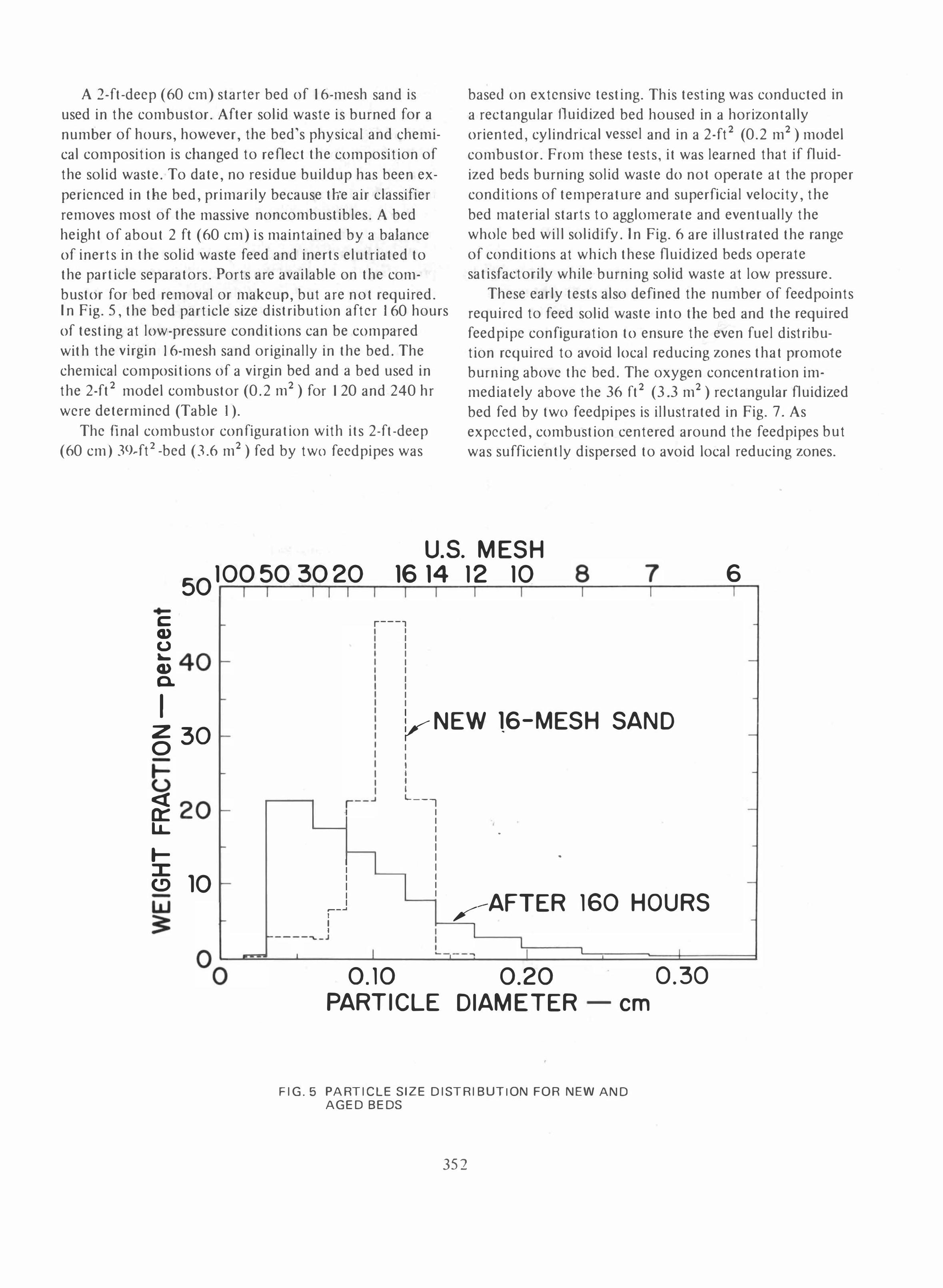
A 2-ft-deep (60 cm) starter bed of 16-mesh sand is used in the combustor. After solid waste is burned for a number of hours, however, the bed's physical and chemical composition is changed to reflect the composition of the solid waste. To date, no residue buildup has been experienced in the bed, primarily because th·e air classifier removes most of the massive noncombustibles. A bed height of about 2 ft (60 cm) is maintained by a balance of inerts in the solid waste feed and inerts elutriated to the particle separators. Ports are available on the combustor for bed removal or makeup, but are not required. In Fig. 5, the bed particle size distribution after J 60 hours of testing at low-pressure conditions can be compared wit h the virgin J 6-mesh sand originally in the bed. The chemical compositions of a virgin bed and a bed used in the 2-ft 2 model combustor (0.2 m2) for 120 and 240 hr were determined (Table I).
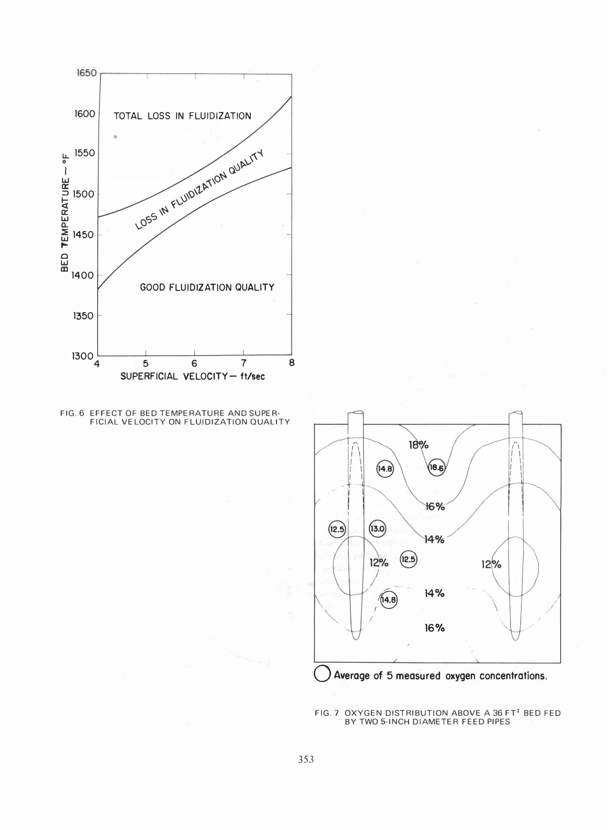
The final combustor configuration with its 2-ft-deep (60 cm) 39-ft2-bed (3.6 m2) fed by two feedpipes was
based on extensive testing. This testing was conducted in a rectangular fluidized bed housed in a horizontally oriented, cylindrical vessel and in a 2-ft2 (0.2 m2) model combustor. From these tests, it was learned that if fluidized beds burning solid waste do not operate at the proper conditions of temperature and superficial velocity, the bed material starts to agglomerate and eventually the whole bed will solidify. In Fig. 6 are illustrated the range of conditions at which these fluidized beds operate satisfactorily while burning solid waste at low pressure.
These early tests also defined the number of feedpoints required to feed solid waste into the bed and the required feed pipe configuration to ensure the even fuel distribution required to avoid local reducing zones that promote burning above the bed. The oxygen concentration immediately above the 36 ft2 (3.3 m2) rectangular fluidized bed fed by two feed pipes is illustrated in Fig. 7. As expected, combustion centered around the feedpipes but was sufficiently dispersed to avoid local reducing zones.
50100503020 u.s. MESH
16 14 12 10 8 7 6 • c Q) (.)
-
Q; 40-c.
I -
� 30 f
t -
� 20-IJ... lI (!)
-
10 -
I I I I I I I I r---,
I I I I I I I I I I
I I I I
V NEW 16-MESH SAND I I I I I I L __ ..,
I I I I I I I I I
-
• I I I I I I
�-� I I I
I
,-AFTER 160 HOURS ------"._J
I I 0.10
PARTICLE
I I
0.20 DIAMETER em
FIG.5 PARTICLE SIZE DISTRIBUTION FOR NEW AND AGED BEDS
352
I
0.30
I
-
-
-
-
-
-
-
-
1650 ,-------,------,-----,------,
1600 TOTAL LOSS IN FLUIDIZATION
Ii.. 1550 o
I w a:: � 1500 « a:: w a.. � 1450 ..... o w 1D1400
1350
•
GOOD FLUIDIZATION QUALITY
13004L.----
5L-.---
6L-.---
7-'-----'
S SUPERFICIAL VELOCITY - ftlsee
FIG.6 EFFECT OF BED TEMPERATURE AND SUPERFICIAL VELOCITY ON FLUIDIZATION QUALITY
353
•
•
A �
I \ I \ I \ I \ I \
(4., I \
I \ 18.6 I \ I \ I \ I -
•
12; Yo �.� 12 Yo
) --,e - \4% ,
\ I , I .
'" •
,
/ • , , 16%
,
o Average of 5 measured oxygen concentrations.
FIG.7 OXYGEN DISTRIBUTION ABOVE A 36 FT' BED FED BY TWO 5-INCH DIAMETER FEED PIPES

PARTICLE SEPARATORS
Three stages of particle separation are employed in the pilot plant to protect the turbine from erosion and to meet air pollution standards. The construction of all three of these vessels is essentially the same in that there is a mild steel pressure vessel insulated by 2 in. (5 cm) of mineral wool and 3 in. (8 cm) of kaowool. The insulation is protected from the hot gas by a stainless steel liner.
The particulates from the fluidized bed combustor contain small drops of molten aluminum covered by a hard aluminum oxide shell that form when aluminum foils, beverage can pull tops, and other aluminum products not separated by the air classifier melt and partially oxidize. I f these aluminum drops are allowed to impinge on a hard surface, they will break, oxidize and form a hard, aluminum oxide deposit. Therefore, care was taken in the design of the particle separators to avoid impact points for the aluminum .particles prior to their collection.
The first stage separator is a 7-ft-diameter (2.1 m) cyclone that gently decelerates and removes the larger aluminum drops and sand while providing additional time for the aluminum ot oxidize'before entering the next separator. The second stage separator contains 48 6-in.diameter (15 cm), reverse flow cyclone tubes, 24 of which are used. The third stage separator contains 100 3th-in.diameter (9 cm) reverse-flow cyclone tuhes, 80 of which arc used.
In the second and third stage separator, the tubes empty ash into a common hopper for removal. Two pneumatic vibrators, attached to each hopper, are used to keep the ash flowing to the outlet.
A double, 2-in.-diameter (5 cm), hall valve airlock unloading system is used to continuously remove ash from each of the three separators. The ash is then pneumatically transferred into a cyclone, which exhausts to a baghouse.
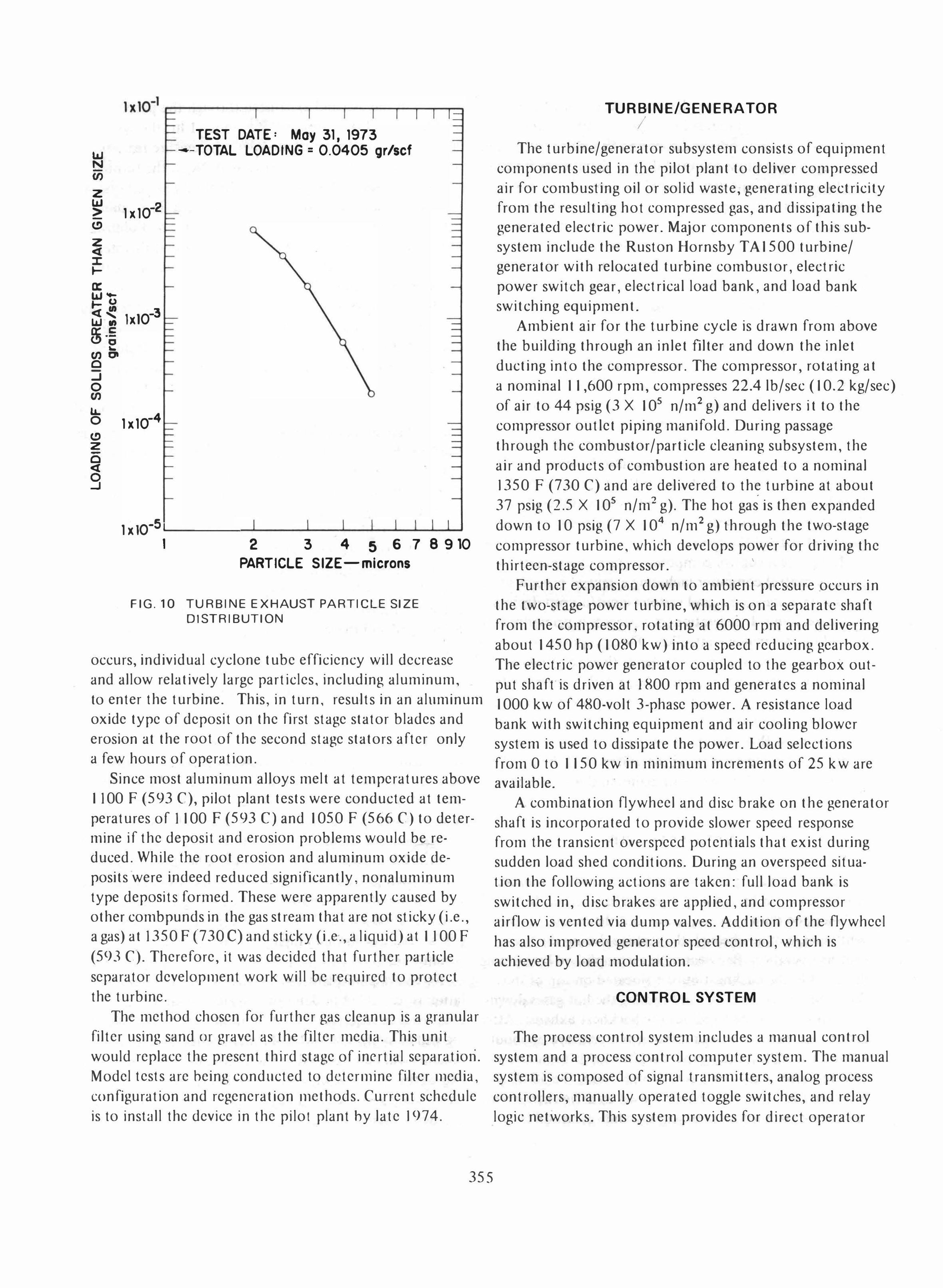
Extensive cyclone tube development work was done utilizing the 2-ft2 (0.2 m2) model comhustor fitted with a singe 6-in.-diameter (15 em) tube followed by a module of three, 3th-in. (9 cm) tubes. A module of 18, 1-3/8-in. (3.5 cm) tubes was evaluated, but abandoned when found to be very prone to plugging in the outlet cone. Numerous ll10del tests were conducted to determine the best tube configur(lt ions to minimize plugging and maximize separation ef f"iciency. The resulting 6-in. (IS cm) and 3Yz-in. (9 em) tuhes and their respective performance cu'rves are illustrated in Figs. 8 and 9. Figure 10 shows the size distribution of the particulate in the turbine exhaust when the part ide separators (Ire operat ing properly.
In the pilot plant separators, the cyclone tubes arc still prone to plugging in the lower cone body due primarily to suspected cross now between the tubes. When this
354
100
I 99 w N -(f) o w b z
� >-. � 90 w u -
It w
o I
FIG.8
8 F I NS, i": rC
� � I
, r* -, 9,02.5 L i-' � t I I 35qf' I I
,-_J 3.75 6
1 1.75
t 15,5
25,5
l • 1 • 3,75
I
I -
-
. -
-
-
-
-
-
-
-
2 3 4 5 6 7 B 9 10 20 PARTICLE SIZE microns
6-INCH DIAMETER CY CLONE TUBE CONFIGURATION AND PERFORMANCE CURVE
100 r-------._----r-�--.-._._rT._------_,
-C OJ u � OJ a.
I 99 W N -(f) 0 w t-O Z
� >-� 90 w -u -L.o.. L.o.. W
FI G. 9
8FINS
� 1,45 t3;
2,25
1.7 I I
... , -I -'r.J 7, I
I I
-.l I I I I L_.J
10,5
3 ,5 t
17,0
j . 221-
2 3 4 5 6 7 B 9 10 PARTICLE SIZE microns
20
3.5-INCH DIAMETER CY CLONE TUr.E CONFIGURATION AND PERFORMANCE CURVE
TEST DATE: May 31, 1973 10.1 --TOTAL LOADING = 0.0405 gr/scf N -(I) Z 10.1
1x1O-2 > -(!) Z � :I: I-0: w� 1- (.) �� lxl0-3 10.1., $ ·S
... (I)'" 0 -...J 0 (I) u..
1x1O-4 0 (!) z -0 � 9
1 x 10⁻⁵ L-__ _ --'-_ _ --'-_-'----''---'---'--"'---'-' 1 2 3 4 5 678910
PARTICLE SIZE-microns
FIG. 10 TURBINE EXH AUST PARTICLE SIZE DISTRIBUTION
occurs, individual cyclone tube efficiency will decrease and allow relatively large particles, including aluminum, to enter the turbine. This, in turn, results in an aluminum oxide type of deposit on the first stage stator blades and erosion at the root of the second stage stators after only a few hours of operation.
Since most aluminum alloys melt at temperatures above 1100 F (593 C), pilot plant tests were conducted at temperatures of 1100 F (593 C) and 1050 F (566 C) to determine if the deposit and erosion problems would be reduced. While the root erosion and aluminum oxide deposits were indeed reduced significantly, nonaluminum type depOSits formed. These were apparently caused by other combpunds in the gas stream that are not sticky (i.e., a gas) at 1350 F (730 C) and sticky (i.e'., a liquid) at 1100 F (593 C). Therefore, it was decided that further particle separator development work will be required to protect the turbine.
The method chosen for further gas cleanup is a granular filter using sand or gravel as the filter media. This unit would replace the present third stage of inertial separatioti. Model tests are heing conducted to determine filter media, configuration and regeneration methods. Current schedule is to install the device in the pilot plant hy late 1974.
355
TURBINE/GENERATOR
/ The turbine/generator subsystem consists of equipment
components used in the pilot plant to deliver compressed air for combusting oil or solid waste, generating electricity from the resul ting hot compressed gas, and dissipa ting the generated electric power. Major components of this subsystem include the Ruston Hornsby T A 1500 turbine/ generator with relocated turbine combustor, electric power switch gear, electrical load bank, and load bank switching equipment.
Ambient air for the turbine cycle is drawn from above the building through an inlet filter and down the inlet ducting into the compressor. The compressor, rotating at a nominal 11,600 rpm, compresses nAlb/sec (10.2 kg/sec) of air to 44 psig (3 X 10⁵ n/m2 g) and delivers it to the compressor outlet piping manifold. During passage through the combustor/particle cleaning subsystem, the air and products of combustion are heated to a nominal 1350 F (730 C) and are delivered to the turbine at about 37 psig (2.5 X 10⁵ n/m2 g). The hot gas is then expanded down to 10 psig (7 X 10⁴ n/m2g) through the two-stage compressor turbine, which develops power for driving the thirteen-stage compressor. '
Further expansion down to ambient pressure occurs in the two-stage power turbine, which is on a separate shaft from the compressor, rotating at 6000 rpm and delivering about 1450 hp (1080 kw) into a speed reducing gearbox. The electric power generator coupled to the gearbox output shaft is driven at 1800 rpm and generates a nominal 1000 kw of 480-volt 3-phase power. A resistance load bank with switching equipment and air cooling blower system is used to dissipate the power. Load selections from 0 to 1150 kw in minimum increments of 25 kw are available.
A comb.ination flywheel and disc brake on the generator sha ft is incorporated to provide slower speed response from the transient overspeed potentials that exist during sudden load shed conditions. During an overspeed situation the following actions are taken: full load bank is switched in, disc brakes are applied, and compressor airflow is vented via dump valves. Addition of the flywheel has also improved generator speed control, which is achieved by load modulation.
CONTROL SYSTEM
The process control system includes a manual control system and a process control computer system. The manual system is composed of signal transmitters, analog process controllers, manually operated toggle switches, and relay logic networks. This system provides for direct operator

control of various system elements. Relay logic networks are incorporated to prevent the operator from implementing unsafe system configurations and to reduce the number of manual operations required during changeover from one configuration to another. Manual control of the proportional valves and of the solid waste feed system is provided by analog process controllers. In the manual mode, the test conductor actuates a thumb wheel which causes an increase or decrease in the signal being sent to the associated controller. A meter on the front of each controller provides an indication of the signal being sent to the controlled unit.
In the automatic mode, the process controller compares a signal from measurement of a preselected system parameter to an operator selected level or set point. The controller then increases or decreases the signal to the controlled unit based on the difference between the measurement and the setpoint. Each controller has provisions for adjusting the system gain. The controllers also have integral circuits where the controller output is a function of the time integral of the error. Some of the controllers have derivative circuits where the output is a function of the rate of change of the error.
The process control computer system incorporates a process control computer including a central process unit, mass data storage unit, and various input/output devices and subsystems. In operation, the process is primarily controlled by the analog controllers. The computer, in turn, supervises the controllers and adjusts their setpoints as required for stable system performance. Solid waste feedrate is modulated to maintain a constant turbine inlet temperature which is equivalent to constant power output at constant mass flow. The load on the generator is constantly modulated by varying the voltage and the number of active load bank resistors to maintain the generator at its set speed of 1800 rpm.
SYSTEM STARTUP
To get the pilot plant on-line from a cold start nominally takes about 5 hr. Initially a plug is inserted in the duct between the third stage separator and the turbine to prevent leakage of air through the turbine during the bed heating operation. Bed heating is accomplished by burning diesel oil in the backheat burner (located on top of the fluidized bed combustor) and forcing the hot gases downward through the bed and out the backheat exhaust. After about 2 hr, the bed is at an average temperature of about 1200 F (650 C). At this time, backheating is terminated and the turbine inlet plug is removed. Next, the 50 hp (37 kw), turbine starter motor is used to drive the turbine compressor to supply fluidizing air while diesel oil is
.
burned in the bed and exhausted through the particle separators and the turbine. After about 1 hr, the system is heated and when the turbine inlet temperature reaches 1200 F, system heating is terminated. Next, the turbine combustor (located in parallel to the fluidized bed system) is fired on diesel oil and the system brought up to about 800 kw power output prior to switching to the fluidized bed. The pilot plant cannot be started without this step because the pressure drop through the system causes the compressor to surge at low power levels. At high power levels, an adequate surge margin exists and the system can be started and operated. Once the system is generating about 800 kw using the turbine combustor, air from the compressor is diverted from the turbine combustor to the fluidized bed and oil combustion is initiated in the fluidized bed. Fuel flow to the turbine combustor is terminated
when its air supply is stopped. During the transition to the fluidized bed combustor the power output droops about 100 kw before recovering. Before feeding the solid waste, the feedline air valves are opened and the fluidizing air valve downstream of the feedline air takeoff is partially Closed to establish air flow through the solid waste feedlines. Typically, about 300 lb/min (I 36 kg/min) or 23 percent of the total combustion air is used to transport the solid waste from the feeder valves into the combustor. Once solid waste feeding is established, the oil flow is terminated and the system operates without any auxiliary fuel.
SYSTEM PER FORMANCE
During the low-pressure, pilot plant acceptance test, the automatically controlled system operated for 48 hr with the exhaust temperature within 30 F (I7 C) of the selected temperature. For 36 hr of the test, the exhaust temperature was maintained at 1400 F + 10 F (760 C + 6 C) with scheduled excursions to 1430 F + 10 F (777 C + 6 C) and 1370 F ± 10 F (743 C + 7 C) for 4 hr each. During a typical high-pressure test, the system operates at a turbine inlet temperature of 1350 F (732 C) and generates a nominal 1000 kw. In Table 2 is a summary of system performance at low and high pressure operating condi tions.
Extensive pilot plant testing after granular filter installation is scheduled to determine system reliability and maintenance requirements. A minimum of 720 hr of testing will be performed in 120-hr increments. System components will be inspected at the beginning, mid-point, and end of the 720 hr testing to determine turbine blade and other component wear rates due to erosion, corrosion, and deposition.
356
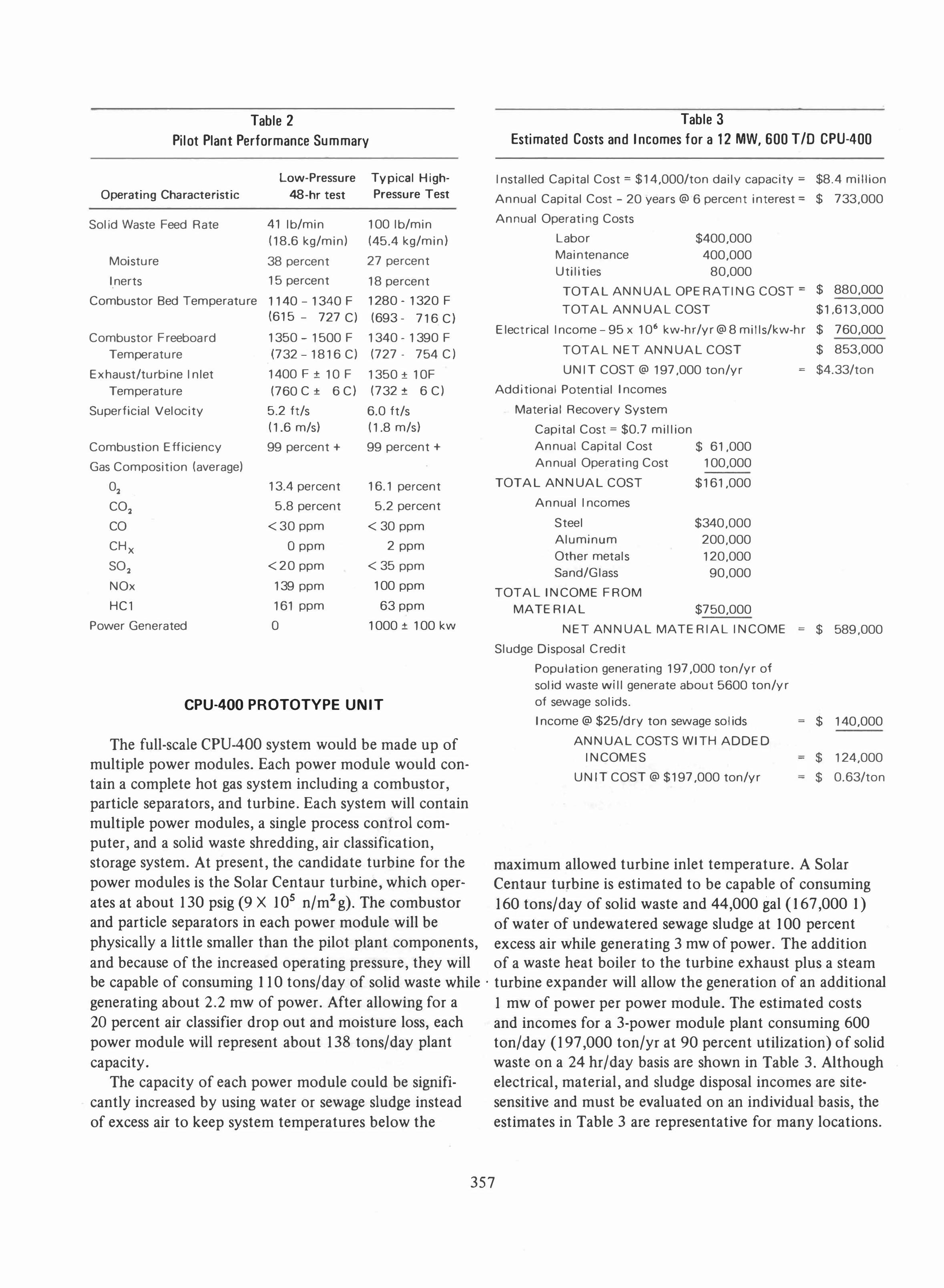
Table 2 Pilot Plant Performance Summary
Operating Characteristic
Sol id Waste Feed Rate
Moisture
I nerts
Combustor Bed Temperature
Combustor Freeboard Temperature
Exhaust/turbine Inlet Temperature
Superficial Velocity
Combustion Efficiency
Gas Composition (average)
0.
CO.
CO
CHx SO.
NOx
HCl
Power Generated
Low-Pressure Typical High-
48-hr test Pressure Test
41 Ib/min (18.6 kg/min)
100 Ib/min (45.4 kg/min)
38 percent 27 percent
15 percent 18 percent
1140 -1340 F 1280 - 1320 F (615 - 727 C) (693 - 716 C)
1350 - 1500 F 1340 - 1 390 F (732-1816 C) (727- 754 C)
1400 F + 10 F 1350 ± 10F (760 C + 6 C) (732 + 6 C)
5.2 ft/s (1.6 m/s)
99 percent +
13.4 percent
5.8 percent
<30 ppm
o ppm
<20 ppm
139 ppm
161 ppm
o
6.0 ft/s (1.8 m/s)
99 percent +
16.1 percent
5.2 percent
< 30 ppm
2 ppm
< 35 ppm
100 ppm
63 ppm
1000 + 100 kw
CPU-400 PROTOTYPE UNIT
The full-scale CPUAOO system would be made up of multiple power modules. Each power module would contain a complete hot gas system including a combustor, particle separators, and turbine. Each system will contain multiple power modules, a single process control com-puter, and a solid waste shredding, air classification,
Table 3 Estimated Costs and Incomes for a 12 MW, 600 T/D CPU-400
Installed Capital Cost = $14,OOO/ton daily capacity = $8.4 million
Annual Capital Cost - 20 years @ 6 percent interest = $ 733,000
Annual Operating Costs
Labor Maintenance Utilities
$400,000 400,000
80,000
TOTAL ANNUAL OPERATING COST = $ 880,000
TOTAL ANNUAL COST $1,613,000
Electrical lncome-95 x 10· kw-hr/yr@8 mills/kw-hr $ 760,000
TOTAL NET ANNUAL COST $ 853,000
UN I T COST @ 197,000 ton/yr
Additional Potential Incomes
Material Recovery System
Capital Cost = $0.7 million Annual Capital Cost $ 61,000 Annual Operating Cost 100,000
TOTAL ANNUAL COST
Annual Incomes
Steel Aluminum Other metals Sand/Glass
TOTAL INCOME FROM MATERIAL
$161,000
$340,000 200,000 120,000
90,000
$750,000
NET ANNUAL MATERIAL INCOME
Sludge Disposal Credit
Population generating 197,000 ton/yr of sol id waste wi II generate about 5600 ton/y r of sewage sol ids.
Income @ $25/dry ton sewage sol ids
ANNUAL COSTS WITH ADDED INCOMES
UNIT COST @ $197,000 ton/yr
- $4.33/ton
- $ 589,000
- $ 140,000
- $ 124,000
- $ 0.63/ton
storage system. At present, the candidate turbine for the maximum allowed turbine inlet temperature. A Solar power modules is the Solar Centaur turbine, which oper- Centaur turbine is estimated to be capable of consuming ates at about 130 psig (9 X lOs n/m2 g). The combustor 160 tons/day of solid waste and 44,000 gal ( 167,000 1) and particle separators in each power module will be of water of undewatered sewage sludge at 100 percent physically a little smaller than the pilot plant components, excess air while generating 3 mw of power. The addition and because of the increased operating pressure, they will of a waste heat boiler to the turbine exhaust plus a steam be capable of consuming 1 10 tons/day of solid waste while· turbine expander will allow the generation of an additional generating about 2.2 mw of power. After allowing for a 1 mw of power per power module. The estimated costs 20 percent air classifier drop out and moisture loss, each and incomes for a 3-power module plant consuming 600 power module will represent about 138 tons/day plant ton/day ( 197,000 ton/yr at 90 percent utilization) of solid capacity. waste on a 24 hr/day basis are shown in Table 3. Although
The capacity of each power module could be signifi- electrical, material, and sludge disposal incomes are site-cantly increased by using water or sewage sludge instead sensitive and must be evaluated on an individual basis, the of excess air to keep system temperatures below the estimates in Table 3 are representative for many locations.
357