cr-120907 - nasaexcept that the specific flow had to be lowered from 42 lbm/ft2-sec (205 kg/m2-sec)...
TRANSCRIPT

. ,, NASA CR-120907 ' PWA-4534
HIGH-LOADING, 1800 FT/SEC TIP SPEED TRANSONIC COMPRESSOR FAN STAGE
I. AERODYNAMIC AND MECHANICAC DESIGN
A.L. Morris, J.E. Halle, and E. Kennedy
PRATT & WHITNEY AIRCRAFT DIVISION UNITED AIRCRAFT CORPORATION
prepared for
NATIONAL AERONAUTICS AND SPACE ADMINISTRATION
NASA Lewis Research Center Contract NAS 3- 13493
W. L. Beede, Project Manager Fluid System Components Division
https://ntrs.nasa.gov/search.jsp?R=19720023124 2020-04-05T02:04:47+00:00Z

i
1. Report No. 2. Government Accersion No.
NASA CR-120907 4. Title and Subtitle
HIGH-LOADING, 1800 FT/SEC TIP SPEED, TRANSONIC COMPRESSOR FAN STAGE, I. AERODYNAMIC AND MECHAN- ICAL DESIGN
A. L. Morris, J. E. Halle, and E. Kennedy 7. Author(s)
9. Performing Organization Name and Address
Pratt & Whitney Aircraft Division United Aircraft Corporation East Hartford, Connecticut 06108
2. Sponsoring Agency Name and Address
National Aeronautics and Space Administration Washington, D.C. 20546
i
3. Recipient's Catalog No.
5. Report Date
6. Performing Orgdnization code September 1972
8. Performing Organization Report No.
PWA-4534 10. Work Unit No.
11. Contract or Grant No.
NAS3-13493 13. Type of Report and Period Covered
Contractor Report 14. Sponsoring Agency Code
9. Security Uanif. (of this report)
Unclassified
5. Supplementary Notes
Project Manager, W. L. Beede, Fluid System Components Division, NASA Lewis Research Center, Cleveland, Ohio
20. Security Classif. (
Unclassified
6. Abstract
A single stage fan with a tip speed of 1800 ft/sec (548.6 mlsec) and hub/tip ratio of 0.5 was designed to produce a pressure ratio of 2.285: 1 with an adiabatic efficiency of 84.Wo. The design flow per inlet annu- lus area is 38.7 Ibm/ft2-sec (188.9 kg/m2-sec). Rotor blades have modified multiple-circular-arc and pre- compression airfoil sections. The stator vanes have multiplecircular-arc airfoil sections.
this page)
7 Key Words (Suggcrted by Authw(s))
Transonic Compressor Stage
21. No. of Pages 22. Rice'
114 $3.00
Precompression Blading
18. Distribution Statement
Unclassified - Unlimited
* For sale by the National Technical Information Service, Springfield, Virginia 22151

HIGH-LOADING, 1800 FT/SEC TIP SPEED
I - AERODYNAMIC AND MECHANICAL DESIGN TRANSONIC COMPRESSOR FAN STAGE
A. L. Morris, J. E. Halle, and E. Kennedy Pratt & Whitney Aircraft Division
United Aircraft Corporation
I. SUMMARY
A highly loaded, high tip speed, single stage compressor has been designed under Contract NAS3-13493. This report presents the details of the aerodynamic and mechanical design. The purpose of the program is to determine the feasibility of using high tip speeds and high aerodynamic loadings to obtain high pressure ratios at acceptable levels of efficiency. The rotor has been designed for precompression (external compression) where inlet Mach num- bers are high. No inlet guide vane or preswirl was used. The stator vanes were designed for zero exit swirl.
The aerodynamic design was based on the approximate parameters specified in the contract except that the specific flow had to be lowered from 42 lbm/ft2-sec (205 kg/m2-sec) to 38.7 lbm/ft2-sec (188.9 kg/m2-sec) in order to prevent meridional Mach number choking. The rotor blade was designed for a constant spanwise pressure ratio of 2.34: 1. Blade losses for the rotor were estimated using a loss model in which shock and profile losses were considered separately. Shock loss estimates were based on relative inlet Mach number and airfoil shape; profile losses were estimated using a correlation of loss parameter versus diffusion factor and precent span. Stator losses were estimated using only a loss parameter correlation.
The rotor was designed using modified multiple-circular-arc blade sections from the hub to 32% span and precompression blade sections from 37% span to the blade tip, with a transi- tion region in between. The purpose of the precompression sections is to reduce the strength of the main passage shock. The rotor was designed using a part-span shroud at 65% span to avoid flutter. The stator was designed with multiple-circular-arc airfoils which approached double-circular-arc geometry toward the outer portion of the span. The design parameters are summarized in Table I.
.
The stator leading edge was located close behind the rotor trailing edge. The calculated abso- lute stator inlet Mach number at the hub was 0.892.
Calculated centrifugal stress, gas bending stress, and untwist stress are within the capabilities of the AMS 4972A titanium alloy to be used for the rotor blades. Vibratory blade stresses should be low since the lE, 2E, and 3E excitations for the first mode are outside of the rig operating range, and the higher order excitations are not expected to occur at low speeds. Although three rotor critical speeds were calculated within the rig operating range, no vibra- tional problems are anticipated since calculated deflections aie within acceptable limits.

TABLE I
DESIGN PARAMETERS
Corrected Speed, rpm
Rotor Tip Speed, ft/sec (mlsec)
12,464
1800 (548.6)
Corrected Flow, lbm/sec (kglsec) 173.8 (78.8)
Corrected Weight Flow Per Annulus Area, 38.7 (1 88.9)
lbm/ft2-sec (kg/m2-sec)
Rotor Pressure Ratio 2.34: 1
Stage Pressure Ratio 2.285 : 1
Rotor Adiabatic Efficiency, Percent 86.8
Stage Adiabatic Efficiency, Percent 84.0
Tip Diameter, Inches (meters) 33.1 (0.84)
Hub/Tip Ratio at Rotor Inlet 0.5
Rotor Tip Solidity 1.635
Rotor Aspect Ratio 2.87
Stator Hub Solidity 2.20
Stator Aspect Ratio 2.22
Stator Exit Flow Angle a t all Radii, Degrees 0
II. INTRODUCTION
Future aircraft powerplants will require lightweight highly loaded compressors which are efficient over a wide range of operation. Pressure ratio per stage can be increased considerably above current levels by increasing rotor wheel speed and blade loadings. However, careful consideration must be given to blade element design in order to avoid severe aerodynamic losses. These losses result from in-passage shocks at high Mach numbers, boundary layer growth due to shock impingement, and high blade loadings. Recent tests, Reference 1*, of a highly
*See page 100 for list of References
2

loaded, 1600 ft/sec (487.7 m/sec), transonic compressor have been very successful; this rotor produces a pressure ratio of 2: 1 at an adiabatic efficiency of 89%. Because of this, the design of a higher tip speed, higher pressure ratio rotor was undertaken. Precompression has been in- corporated into the blade design in order to maintain a high level of efficiency. The precom- pression blade design is based on the external compression principle, described in Reference 2.
This report presents the aerodynamic and mechanical design of a single stage fan with a tip speed of 1800 ft/sec (548.6 m/sec) and an inlet hub/tip ratio of 0.5. The design flow per inlet annulus area is 38.7 lbm/ft2-sec (1 88.9 kg/m2-sec). No inlet swirl is used and the design stator exit swirl is zero. The design stage pressure ratio is 2.285 : 1, and the predicted stage adiabatic efficiency is 84.0%.
111. FLOWPATH AND VECTOR DIAGRAM DESIGN
A basic stage configuration consisting of no inlet guide vanes, hubltip ratio of 0.5 at the rotor leading edge, and aspect ratios of 2.87 and 2.22 for the rotor and stator was specified by contract.
The flowpath design evolved from a series of iterations. All values presented are from the final iteration except where otherwise noted. The iteration was started using a reasonable flowpath shape, estimated flow blockages, and estimated efficiency profiles. The axisymmetric stream- line analysis calculation outlined in Appendix 1 was used to obtain velocity vectors and flow conditions in the flowpath. This information, together with assumed rotor and stator solidi- ties, was used to design rotor and stator blade elements. Adjustments were made to the flow- path shape and blade solidities to control velocities and loadings, and efficiencies were reesti- mated using these new loadings and aerodynamic conditions. Blade sections were defined after each iteration to determine the location of blade leading and trailing edges for use in the streamline calculation. The final flowpath design was compatible with blade element designs and the mechanical design.
Rotor losses were calculated as the sum of profile losses and shock losses. The profile losses were calculated using a correlation of loss parameter, ZJ, cos p'2 , versus diffusion factor and
percent span. Shock losses were calculated for each particular blade element as described in the Rotor Blade Design section. Different shock loss models were used for the multiple- circular-arc sections (hub to 32 percent span) and the precompression blade sections (37 to 100 percent span). The difference in calculated shock losses for the two airfoil types made it necessary to fair the estimated shock losses in the region from 17 to 54 percent span from the hub. Figure 1 shows the radial distributions of calculated shock total pressure recovery for the MCA and precompression shock models and the faired region between the two models. Figure 2 shows the final radial profile of estimated shock loss coefficients calculated from this pressure recovery curve and the total loss coefficient for the rotor blades.
20
Stator losses were calculated using a correlation of loss parameter versus diffusion factor and percent span. Figure 3 shows the final radial distribution of stator loss coefficient.
3

Blockages were included in the aerodynamic design to account for boundary layer growth on the casing walls and for the presence of the rotor part-span shroud at 65 percent span from the hub. Flow blockage due to casing boundary layers was estimated based on data from Pratt & Whitney Aircraft’s research programs. To account for the presence of the part-span shroud, a blockage equal to the percent of total annulus area occupied by the shroud was applied locally at the exit of the rotor and to the inlet of the stator; one-half this shroud block- age was applied locally to the rotor inlet and stator exit stations. A constant radial value of blockage due to casing boundary layers was applied at these stations in addition to the part- span shroud blockages. The spanwise blockage factor distributions, in the vicinity of the part- span shroud, are shown in Figure 4. These distributions of flow blockage were used in the streamline analysis program. Table I1 lists these blockages in terms of radial averages.
TABLE I1
FLOW BLOCKAGES (PERCENT OF TOTAL FLOW AREA)
Part-Span Blade Row and Station Casing Boundary Shroud To tal Number (Figure 6) Layer Blockage Blockage Blockage
Rotor Leading Edge (1) 2.0 0.6 2.6
Rotor Trailing Edge (2) 3.0 1.2 4.2
Stator Leading Edge (3) 3.0 1.2 4.2
Stator Trailing Edge (4) 4.0 0.6 4.6
The flowpath, including stage inlet and exit ducting, is shown in Figure 5. Figure 6 shows the rotor and stator portion of the flowpath in more detail. A highly convergent flowpath was necessary to keep end wall loadings of both rotor and stator within acceptable limits. High blade solidities were selected to control loadings. Figure 7 shows the spanwise distribution of rotor and stator solidities.
The large convergence together with relatively high aspect ratios gave wall slopes which caused the meridional velocity at the rotor leading edge to accelerate in the mid-span region and de- celerate near the walls. Bow wave losses and blockages at the rotor leading ed es further in- creased the meridional velocity. For the desired specific flow of 42 lbm/sec-ft (205 kg/m2- sec) the meridional Mach number at the center of the span became so high that leading edge blockages caused the flow to choke before it could enter the blade channel. Mid-span choke problems caused by abrupt flowpath convergence are discussed in Reference 3. In order to avoid choking, the flowpath at the rotor leading edge plane was designed with large radii of curvature, and the specific flow was lowered to 38.7 lbm/ft2-sec (1 88.9 kg/m2-sec). A com- parison of the inlet meridional Mach number profiles for 42 and 38.7 lbm/ft2-sec (205 and 188.9 kg/m2-sec) is shown in Figure 8. Calculation of boundary layer shape factors along the inlet walls using the method of Reference 4 indicated that the decelerating meridional velocity would not cause the end wall boundary layer to separate.
9
4

Figure 9 shows the rotor and stator inlet and exit meridional velocity profiles. The average velocity at the stator exit was 680 ft/sec (207 mlsec). Inlet Mach numbers for the rotor and stator are shown in Figure 10. The rotor inlet relative Mach number is supersonic from 9.5 percent span to the tip. The rotor exit relative Mach number is subsonic throughout the span. The stator inlet Mach numbers vary from approximately 0.9 at the hub to approximately 0.7 at the tip. By minimizing the gap between the stator leading edge and the rotor trailing edge, the absolute stator inlet Mach numbers and loadings were minimized.
Figure 1 1 shows the rotor inlet and exit relative air angles along with the spanwise stator in- let angies. The stator discharges axially, 0'3 = 0". An upturn in the rotor exit relative air angle, 0'2, occurs between 90 and 100 percent span in the boundary layer region due to the high tip losses estimated for the rotor. Difficulties were encountered in selecting blade sec- tions near the tip because of this abrupt rise in 0'2 and made it necessary to fair a continuous curve of 0'2 versus span through the rotor tip region. The faired /3'2 curve is shown in Figure 1 1.
Rotor and stator diffusion factors are shown in Figure 12. Hub D-factors for the rotor and stator are quite high even though the design has high solidity rotors and stators. Stall char- acteristics of this stage are expected to be strongly influenced by these high hub loadings.
Figure 13 shows the spanwise distribution of rotor and stage adiabatic efficiencies. The mass- averaged efficiencies are 86.8 percent for the rotor and 84.0 percent for the stage.
Spanwise distributions of local specific flow, (W/A)loc. = p Vz, at the rotor and stator lead- ing and trailing edges are shown in Figure 14, The decrease in specific flow at the rotor tip from leading to trailing edges and the large increase across the stator tip in relationship to the average increase across the stator, are caused by the expected rotor tip losses. High rotor work in this high loss area gives a large swirl velocity and a low axial velocity so that tip stream tubes expand through the rotor. When the swirl is removed by the stator, the outer stream tubes contract. The stream tube expansions and contractions at the tip are beyond the ex- perience on which the blade design system is based and some discretion in selecting airfoils in the outer span was required; this will be discussed further in Sections IV and V.
The design velocity vector data calculated along streamlines at the rotor and stator leading and trailing edges are tabulated in Appendix 2, Aerodynamic Summary.
IV. ROTOR BLADE DESIGN
The rotor blade was designed to produce a total pressure ratio of 2.34: 1 at a tip speed of 1800 feet per second (548.6 mlsec). There are 38 rotor blades with an aspect ratio of 2.87 (based on average blade length and axial projected chord at the hub) and a tip solidity of 1.635.
The rotor blade consists of multiple-circular-arc (MCA) airfoil sections from hub to 32% span and precompression (PC) sections from 37% span to the tip, with a transition region in be- tween. Transition blade sections were necessary to provide reasonably smooth airfoil shapes
5

6
between the MCA and precompression airfoil sections. Precompression airfoils were chosen to reduce shock losses wherever possible, i.e., wherever the relative inlet Mach number and blade leading edge wedge angle allowed an attached oblique shock. Airfoil sections were designed on conical surfaces approximating stream surfaces of revolution.
A preliminary parametric study of blade mechanical properties was made assuming MCA air- foils at all spanwise locations since the MCA sections are more easily specified than PC sec- tions. The more complicated PC airfoil design was begun after general mechanical design criteria were established. Essentially the same mechanical properties were maintained in the blade with PC as MCA airfoils by adjusting the PC section at each spanwise position to obtain the same cross section area.
MultipleCircular-Arc Design
MCA sections extend from the root t o 32% span. True multiple-circular-arc airfoils were used in the design procedure. These airfoils were subsequently thinned to provide more flow area, and these thinned MCA airfoils will be referred to as “modified” MCA airfoil sections in this report.
Airfoil sections were defined by specifying total and front chord, total and front camber angle, maximum thickness and its location, and leading and trailing edge radii, as shown by Figure 15a. The front chord was selected to provide a transition point just forward of an assumed normal shock impingement point on the suction surfaces.
For the MCA blade sections, a normal shock is assumed a t the first covered section of the blade passage as shown in Figure 15b. A Mach number upstream of the assumed normal shock is calculated by using the equations of continuity and conservation of angular momen- tum. This calculation accounts for stream tube contraction and radius change. Next, the crit- ical area ratio (A/A*) resulting from the Mach number calculation is adjusted to account for blade blockage by multiplying the A/A* by the ratio of blade entrance channel width to (s cos $1). The resulting A/A* determines the upstream shock Mach number. The shock total pressure recovery (shown in Figure 1) was than computed based upon the assumption of a normal shock a t this upstream Mach number.
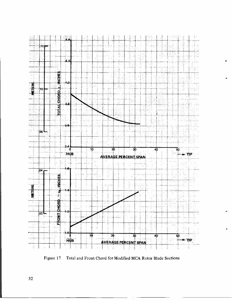
Maximum thickness-to-chord ratio at the root is 0.077 which gives calculated combined steady state stresses, including untwist stresses, within the allowable limits of AMS 4972A titanium alloy selected for blade material. The spanwise distribution of maximum thickness- to-chord ratio is shown in Figure 16. Total and front chords for the modified MCA rotor blade are shown in Figure 17.
c
Incidence angle to the suction surface at the leading edge versus span is shown in Figure 18. Two incidence criteria were used: 1) subsonic and transonic MCA, and 2) supersonic MCA.
Rotor incidences for the subsonic and transonic blade sections were set based on measured minimum loss incidence angles in Reference 1. Rotor incidence for the supersonic MCA

portion of the blade was selected as +1.5 degrees to the suction surface at a location half- way between the leading edge and the emanation point of the first captured Mach wave. This incidence selection is based on experience and accounts for bow wave shock loss, blade leading edge blockage, and development of the suction surface boundary layer.
The ratio of minimum blade channel flow area to critical area, A/A*, was chosen as 1.02 to prevent choking. Distributions of A/A* through five blade channels between 0 and 30.3 per- cent span are shown in Figure 19. Area distributions are along conical surfaces. The critical A/A* ratio was calculated knowing the channel width, shock loss, and the assumptions of a linear specific flow variation from the !eading edge to the trailing edge and a linear profile loss distribution from the blade channel entrance to the trailing edge. Front camber was the main parameter used to control blade channel width. An improved A/A* calculation tech- nique accounting for streamline radius ratio was developed after completing the rotor design. This calculation showed that the channel areas for sections from 9 to 32 percent of the rotor span were too small. Additional flow area was obtained by locally thinning the standard MCA airfoils as shown in Figure 20. The A/A* distributions for this modification are in- cluded in Figure 19. Blade total and front camber angle distributions are shown in Figure 21.
Deviation was estimated using Carter’s rule plus a correction based on a correlation of test data from Reference 1. The design deviation and Carter’s rule deviations for the MCA blade sections are shown versus span on Figure 22.
Precompression Blade Design
For the outer radii, a low shock-loss precompression blade section was used because of the high rotor tip speed and high inlet relative Mach number associated with this rotor. Figure 23 is a schematic of the precompression airfoil. A general description of the precompression blade design is presented in the following paragraphs.
The precompression design model assumes that the shock across the channel entrance must be oblique and attached to the leading edge of the airfoil. Flow conditions upstream of the first captured Mach line are adjusted to account for the bow shock system which propagates upstream of the rotor inlet plane. The concave surface (BC in Figure 23) is the precompres- sion ramp. The curvature of this ramp generates a series of compression waves which diffuse the supersonic flow. The wave system is designed to coalesce near A’, slightly downstream of the rotor inlet plane. The precompression wave system lowers the Mach number of the flow across the passage entrance, reducing the total pressure loss associated with the oblique shock (A’ -D on Figure 23). The flow deflection across this oblique shock is equal to the effective leading edge wedge angle (blade wedge angle plus boundary layer displacement) plus the pre- compression angle.
The shock A’ -D is constructed in increments across the gap to account for gapwise changes in flow conditions upstream of the shock. Shock losses are calculated for each increment and are mass averaged across the gap to obtain the oblique shock loss of the blade element. Channel flow downstream of the oblique shock is subsonic, and turning and stream tube area are made compatible with exit aerodynamic conditions.
7

Development of the blade suction surface AB beings by aligning the aerodynamic surface (blade surface plus boundary layer displacement) to a constant angular momentum stream- line from the leading edge to the first captured Mach wave. Suction surface curvature in seg- ment CD is designed to adjust the supersonic flow upstream of the shock to be compatible with the shock deflection and subsonic flow condition downstream of the shock. Iterations were made on surface shape until compatibility was achieved, accounting for effect of radius change and stream tube convergence (or divergence).
The suction surface immediately behind the shock impingement, D, is aligned with the flow direction downstream of the shock. The surface is rounded at D to allow for boundary layer thickness changes in the region of the shock impingement. Channel area is blended from the value at D to the area determined by the core flow at the channel exit. A cosine variation of stream tube area determines the locus of points which define the suction surface (DG). The cosine variation equations are given in Appendix 3.
The pressure surface segment AE follows a free streamline downstream of the oblique shock. Segment FG of the pressure surfaces is designed to guide the flow to the desired exit angle. Segment EF blends smoothly between AE and FG. The chordwise locations of the pressure surface points, E and F, are tabulated in Appendix 4.
The resulting mean-line incidence and deviation angles for the entire blade are shown in Fig- ures 24 and 25, respectively. The mean-line metal angles used in the calculation of these fig- ures are average pressure and suction surface metal angles at the leading and trailing edges of the developed blade sections.
Precompression blade sections were designed for a radial distribution of cross-sectional area determined from the preliminary MCA design. The main purpose of this requirement was to provide good mechanical properties and blending of the MCA and PC blades. The blade span- wise cross-sectional areas are shown in Figure 26; this curve shows the areas for the modified MCA blade (dashed line) as well as the true MCA areas (solid line). The PC airfoil cross- sectional areas, which are shown in Figure 26, were obtained primarily by controlling the blade leading edge wedge angle and leading edge radius (Figure 27). The leading edge wedge angle and the location of the pressure surface point, E, (Figure 23) were chosen to avoid local chordwise narrowing of blade elements which could result in concentrations of vibra- tional stress.
Channel area between the blades was calculated from the aerodynamic blade surface contours and estimated stream tube height from the streamline analysis. This area was then increased to account for boundary layer displacement thicknesses which were determined using the boundary layer calculation of Reference 4. In this calculation, the abrupt pressure rise, caused by the passage shock wave, is spread linearly across the shock impingement- - from five bound- ary layer thicknesses upstream of the shock impingement point to the trailing edge.
0
Y
A minimum critical area ratio (A/A*) was calculated for the precompression sections based upon channel width between blades, bow wave losses, shock losses, streamline radius changes, and specific flow. This minimum A/A* ratio occurs just downstream of the oblique shock
8

(A’D). The minimum A/A* ratios for the precompression blade sections are plotted span- wise in Figure 28 for three types of assumed shock losses. Curve A of Figure 28 is computed on the basis of the design shock loss, i.e., the oblique shock of Figure 23; for this design case, the (A/A*),i, ranged from 1.02 to 1.065, with a drop-off at the tip region due to high end wall losses. Curve B in Figure 28 is the minimum A/A* distributions based on a normal shock at the channel entrance Mach number (e.g., depicted in Figure 15b), and curve C is based on a normal shock at the inlet relative Mach number, MI’. Figure 28 shows that the flow will start if the blades are subjected to normal shock losses based on a channel entrance Mach number, but most of the flow in the outer 40 percent span will not start if these losses are based on MI’; i.e., the Kantrowitz-Donaldson criterion (Reference 5). It is thought, how- ever, that the noma1 shock at MI’ is an extreme condition which will not occur due to the presence of the diffusing wave system associated with the precompression ramp. I t is more reasonable to expect that in starting, the rotor passage will encounter a normal shock at a precompressed Mach number, so that the starting (A/A*),in distribution may be similar to curve B. I t is believed that adequate flow area is provided for design entrance flow con- ditions to be established in the precompression blade sections under these conditions.
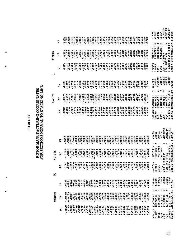
Blade chord, leading and trailing edge metal angles, and precompression ramp angles are shown in Figures 29, 30, and 31 for conical surfaces on streamlines. Rotor blade geometry is tabulated in Appendix 4, Table VII. Also included in Appendix 4 is a graphical description of an airfoil on the unwrapped conical surface (Figure 50). This figure is used in conjunction with Table VII. Rotor tip geometry was selected using the previously discussed faired p’2 curve of Figure 1 1. For manufacturing purposes, the airfoil sections were defined on planes normal to a radial (stacking) line. The resultant blade coordinates are presented in Appendix 5 , Table IX. Airfoil coordinate labels used in Table 1X are graphically defined in Figure 5 1 (included in Appendix 5).
Transition
The region of the blade from 32 to 37% span provides transition from the modified MCA to PC sections. The last MCA conical section is at 32% span and the first PC section is at 37% span. The blade section stacking program which defines blade surfaces by a parabolic curve fit between conical input sections was used to determine transition blade sections. For manu- facturing purposes, the airfoils in the 32-37 percent span region were defined on planes nor- mal to a radial line.
V. STATOR VANE DESIGN
The stator has multiple-circular-arc airfoil sections (Figure 15a) with sections at the outer span approaching double-circular-arc (DCA). Airfoil sections were designed on conical sur- faces approximating streamsurfaces of revolution.
The aerodynamic chord length tapers linearly from 2.48 inches (0.063 m) at the hub to 2.6 inches (0.066m) at the tip. The stator has 60 vanes resulting in a hub solidity of 2.2. Aspect ratio is 2.22 based on average blade length and axially projected chord at the hub. Maximum thickness-to-chord ratio is 0.07 at the tip tapering learlrly to 0.05 at the hub. This stator vane thickness distribution was selected to provide mechanical integrity and low blade element loss.
9

Front chord length (cf in Figure 15) for hub sections was selected to set the transition point just forward of the intersection on the suction surface of a line drawn from the leading edge of an adjacent blade and normal to the flow. Airfoil sections near the outer case have front chords approximately one-half the total chord and front cambers approximately one-half the total camber. Therefore, these sections are essentially DCA airfoils. Figure 32 shows the spanwise distributions of c sin @/2 which is the average airfoil mean-line radius of
cf sin $12 curvature divided by the front section-mean-line radius of curvature. This parameter equals 1 .O for DCA airfoils and becomes smaller as the front section is uncambered relative to a DCA airfoil. Figure 33 shows the chordwise location of airfoil maximum thickness versus span.
Incidence angle was set at zero degrees to the suction surface in the near-sonic flow region at the hub, blending into minimum loss incidence angles for double-circular-arc sections near the tip (Figure 34). Camber distribution was used to control throat area in the channel between adjacent vanes. The optimum ratio of capture area to throat area, which provides minimum loss (Reference 6) varied from 0.97 at the hub to 0.985 a t the stator tip. This capture-to-throat area parameter was used to set throat areas. Figure 35 shows the axial distributions of A/A* in channels between stator airfoil sections.
Incidence angle and front camber did not control throat areas in the outer 15 percent span where the extremely low ratio of inlet to exit specific flow, @Vz)3/(pVz)4, caused the minimum throat area to occur at the channel exit (Figure 3 5 , 100 percent span). Minimum channel flow area is lower than the optimum indicated by Reference 6, although A/A* is adequate to prevent choking. Incidence angle selection was complicated by the unusually low specific flow ratio, (pVz)3/(pVz)4, and high inlet air angle which fell outside the range of available stator blade-element data. Pratt & Whitney Aircraft cascade data for geometrically similar DCA cascades but with specific flow ratios closer to 1 .O were considered most applicable and were used to select stator tip incidence angles.
Stator deviation angles were determined using Carter’s rule plus an adjustment based on data from References 1 and 7. The spanwise distribution of Carter’s rule and design devia- tion angles are given in Figure 36.
Figure 37 presents mean-camber-line metal angles versus span, and Figure 38 presents front and total camber angles. All angles in these figures are measured on conical surfaces on which the airfoils were designed. Stator vane geometry on conical surfaces is summarized in Appendix 4, Table VIII. Also included in Appendix 4 is a graphical description of an airfoil on the unwrapped conical surface (Figure 50). This figure is used in conjunction with Table VIII.
For manufacturing purposes, airfoil sections were defined on planes normal to a radial line which passes through the center of gravity of the hub section. Coordinates of these sections are tabulated in Appendix 5, Table X. Airfoil coordinate labels used in Table X are graph- ically defined in Figure 5 1 (included in Appendix 5).
10

' VI. STRUCTURAL AND VIBRATION ANALYSIS
The mechanical design included an investigation of the rotor and stator airfoil steady and vibrational stresses and flutter parameters. The natural modes of the rotor and stator systems were calculated and a rotor-frame critical speed analysis was performed to investigate the vibrational characteristics of the fan stage.
The final design is stress limited in the blade attachment to a mechanical speed of 13,650 rpm which is 109.5 percent of the standard day design speed of 12,464 rpm and 106.5 per- cent of design speed based on a 90°F (305.2'K) rig plenum temperature. All mechanical anaiyses are based on this 90°F plenum temperature.
A. Rotor Blade and Stator Vane Stresses
Combined centrifugal pull and untwist rotor blade stresses were calculated at 1 10 percent of design speed and results are shown in Table I11 along with the allowable stresses for the blade material, AMS 4972A titanium alloy bar stock, based on 200'F (366.3'K) metal temperature. The maximum combined centrifugal pull and untwist stress of 77,700.psi (536 x 1 O6 N/m ) occurs at 13 percent span, near maximum thickness on the concave side of the airfoil. This stress is comparable to stress levels present in experimental and production blades and is well below the allowable stress of 94,000 psi (648 x lo6 N/m2). The maximum vibratory stress occurs at 22 percent span near the trailing edge on the concave side of the airfoil. The static stress in this area is only 54,000 psi (372 x 1 O6 N/m3). Figure 39 shows these maximum stress locations. A modified Goodman diagram, Figure 40 indicates that, at the maximum steady state stress level of 77,700 psi (536 x
1 O6 N/m2). Since no low order resonances are expected in the blade's high speed opera- ting range, the actual vibratory stress levels should be less than the allowable value of 10,000 psi (60 x 1 O6 N/m2) indicated by the Goodman diagram for this point on the blade. During testing, the vibratory stress will also be limited to 10,000 psi (69 x 1 O6 N/m2).
2
1 O6 N/m z ), the maximum allowable vibratory stress is slightly above 10,000 psi (69 x
Gas bending stresses with centrifugal restorations were calculated at design speed for various tangential tilts of the blade, see Figure 41. Airfoil stresses were minimized for the combination of load and no-load conditions. The selected tangential tilt is 0.050 inch (0.00127 m) which results in a maximum tensile bending stress of 7000 psi (48 x lo6 N/m2) at 12,464 rpm.
The part-span shroud was designed to insure minimum aerodynamic interference while providing adequate strength under centrifugal loading and bearing forces. The part- span shroud is located at 65 percent of span. A sketch of the part-span shroud is shown in Figure 42. The Z* ratio, defined as shroud section modulus/adjacent airfoil section modulus, has a value of 0.84 which is consistent with successful experience. Pertinent shroud stresses are shown in Table 111.
Stator vane (AMs 5613 stainless steel material) gas bending stresses were calculated assuming both fixed and pinned ends. The maximum bending stress of 38.300 psi
11

(264 x 1 O6 N/m2) was well below the allowable of 108,000 psi (755 x lo6 N/rn2). Maximum allowable vibratory stress limits for stator vanes are established based upon test experience with similar stator vane and attachment designs. For this stator, the test limit was the same as for the rotor; i.e., 10,000 psi (69 x lo6 N/m2). This stress limit is conservative because the stator's steady state stresses are lower than the rotor's steady state stresses, and, like the rotor, there are no critical stator vane resonances in the operating range.
TABLE 111
CALCULATED STRESSES FOR ROTOR BLADE, BLADE DISK, AND STATOR VANE
38 Rotor Blades 60 Stator Vanes
Disk
AMs 4972A (titanium alloy) AhlS 561 3 (stainless steel) AMs 6415 (low-alloy steel)
Assumed Operating Conditions
N = 1 IWof design speed, 90°F (304.2'K) plenum temperature, except where noted
T= 200'F (366.3OK) metal temperature
Stress - Blade airfoil max. combined
stress
Blade airfoil max. root com- bined stress corrected for platform angle (at leading edge)
Blade shroud bearing stress
Blade shroud bending stress
Blade attachment max. com- bir.ed stress (106.5% speed)
Blade attachment max. bearing stress (1 06.5% speed)
Disk lug max. combined (106.5% speed)
Disk lug bearing stress (106.5% speed)
Disk average tangential stress
Disk max. radial stress
Vane airfoil max. bending stress
Calculated
77,700 psi (536 x IO6 N/m2)
77,600 psi (536 x lo6 N/m2)
4075 psi (28 x l o6 N/m2)
64,700 psi (446 x 1 O6 N/m2)
71,022 psi (490 x 1 O6 N/m2)
87,532 psi (604 x 1 O6 N/m2)
63,633 psi (439 x l o6 N/m2)
87,532 psi (604 x 1 O6 N/m2)
82,950 psi (572 x 1 O6 N/m2)
74,000 psi (510 x lo6 N/m2)
38,300 psi (264 x 1 O6 N/m2)
All0 wa ble
94,000 psi (648 x IO6 N/m2)
94,000 psi (648 x 1 O6 N/m2)
5000 psi (34 x l o 6 N/m2)
66,000 psi (455 x l o 6 N/m2)
7 1.077 psi (490 x 1 O6 N/m2)
84,600 psi (583 x l o 6 N/m2)
103,367 psi (713 x l o 6 N/m2)
122,400 psi (844 x l o6 N/m2)
106,000 psi (731 x lo6 N/m2)
96,000 psi (662 x 1 O6 N/m2)
108,000 psi (745 x l o 6 N/m2)
.@
0
12

B. Rotor Blade Attachment and Disk Stresses
Critical speed considerations required that disk rim weight be minimized, necessitating the selection of a dovetail attachment rather than a firtree attachment. The final blade attachment design is stress limited to a mechanical speed of 13,650 rpm which is 109.5 percent of the standard day design speed of 12,464 rpm and 106.5 percent of design speed based on a 90°F (305.2'K) rig inlet temperature. The bearing stress in the blade attachment exceeds the nominal allowable by 3.5 percent. This is acceptable since the allowable limit is conservative and intended for production engines. All disk (AMs 641 5 low-alloy steel material) stresses are well below allowable limits. See Table I11 for a s~im- mary of blade attachment and disk stresses.
The airfoil root stress/blades attachment stress is approximately 2.0, insuring that the attachment can withstand vibratory stresses higher than the airfoil can tolerate.
C. Rotor Blade and Stator Vane Resonances
Coupled blade-disk resonances which might be excited in the operating range were avoided by the proper choice of shroud location, shroud angle, blade material, and disk geometry and material. Low order excitation from circumferential distortion or other possible inlet pressure variations will not excite the system because the blade and disk were designed to insure that natural modes for the system would not occur at frequencies close to one, two or three excitations per revolution (lE, 2E, or 3E) during high speed operation. The bladed disk resonance diagram is shown in Figure 43. Per- formance testing will be avoided at those speeds where higher order resonances (6E, 8E, or 1 OE) might occur. However, there are no struts or instrumentation in the system to excite these resonances. The first bending mode 3E frequency margin is more than 8 percent at 105 percent of design speed, and more than 5 percent at 1 10 percent of design speed, which is considered adequate. Blade strain gages will indicate any resonant conditions that exist and test speeds can be adjusted accordingly to avoid operation at these resonant conditions.
The blade tip dynamic stress distribution in the first chordwise bending mode is shown in Figure 44. The maximum stress is six times the stress at maximum blade thickness and occurs at 25 percent chord. However, no tip fatigue problems are expected since the first tip chordwise bending mode occurs in the region of low static stress and is not excited by vane passing order or any 8E or lower frequency excitations as shown in Fig- ure 45. A 1 OE resonance occurs in the high speed operating range but no evidence of this excitation was found in the stress records of a fan stage using the same inlet case and almost identical instrumentation. Higher order resonances are not expected to cause problems since they occur at lower speeds. The maximum stress location caused by the chordwise bending modes will be determined so that the blade tips can be adequ- ately strain gaged.
13

The stator vane resonant frequencies were calculated assuming that the vanes were fixed at both ends of the airfoil and then adjusted based on past testing of similarly mounted vanes. The stator resonance diagram is shown in Figure 46. At design speed, the only resonance that exists is 5E for which there is no anticipated source of excitation. Below design speed the 38E vane resonance or other resonances can be avoided by proper selection of test speeds to avoid resonant conditions indicated by vane strain gages. As an additional safeguard against encountering high stresses throughout the operating range, the stator vane inner diameter shank will be supported with a flexible bushing as shown in Figure 47. Damping of stator vane vibration by supporting vanes in a flexible (polyurethane) compound has been successfully demonstrated in an engine program.
D. Rotor Blade and Stator Vane Flutter
To avoid rotor blade flutter a part-span shroud was located at 65 percent span from the hub with a shroud contact angle of 25 degrees. The supersonic torsional flutter para- meter (V/bot) was calculated for the portion of the blade above the part-span shroud. The V and b terms are the relative velocity and semi-chord at 75 percent span for this portion of the blade, and the ut term is the torsional frequency of the blade portion above the shroud assuming the blade is fixed at the part-span shroud location. The flutter parameter was 1.02 at design speed and 1.04 at 1 10 percent of design speed; these values are below typical values where flutter problems occur; therefore, no super- sonic torsional tip flutter is expected throughout the high speed running range.
The stator vane bending flutter parameter and torsional flutter parameter were calcu- lated for these vanes; the calculated points fall well into the successful experience (no flutter) area.
E. Oitical Speed
A rotor-frame critical speed analysis was performed to determine the vibrational character- istics of this rig. The analysis includes all of the significant structural members and uses the spring rates, masses, and gyroscopic stiffening of the system. The compressor rig spring location and spring rates are shown in Figure 48.
Three critical speeds occur within the rig operating range at 5500, 1 1,800 and 12,500 rpm. A fourth one occurs at 14,800 rpm which is above the maximum operating speed. The mode shapes at these four speeds are shown in Figure 49. To determine if the vi- bratory amplitudes of these modes are acceptable, a forced response analysis was per- formed. This analysis is similar to the critical speed analysis except that an unbalance is simulated and the resultant vibratory deflections calculated. Deflections were calcu- lated at all significant rotor and case locations for an unbalance of one (1) ounce-inch (72 x lo5 kg-m) located at each of five ( 5 ) locations: disk, No. 2 bearing, diaphragm coupling, forward spline, and rear spline. Table IV gives a listing of estimated deflec- tions for the four (4) critical speeds, or modes.
14
J.

15

The 11,800 rpm mode was found to be the most sensitive to unbalance. The largest estimated deflections (for 1 ounce-inch unbalance) were 0.019 inches (0.0005 m) at the inlet fairing and 0.01 2 inches (0.0003 m) at the disk. Deflections at the inlet fairing are no threat to rig safety. The rotor assembly (consisting of disk, blades, forward and rear shaft assemblies, and diaphragm coupling) will be balanced to better than 0.05 oz-in (36 x kg-m) unbalance resulting in a maximum disk deflection of 0.005 inches (0.00013 m). This is considered acceptable since the minimum blade tip clear- ance is 0.040 inches (0,0010 m) and the rig is adequately instrumented to detect and avoid critical speed regions. Also, actual sensitivity to unbalance may be considerably less since conservative values of damping coefficients were used in the analysis.
16

17

Figure 3 Stator Vane Loss Coefficient (Design)
18

Figure 4 Spanwise Distribution of Local Blockage Factor in Vicinity of Part-Span Shroud
19

m E /
U
/ c y
0 P
0 L"
I I I I :: c
S ~ H ~ N I - sniawn
0 0 0
L I I I I 2 2 2 r Lo 0 Lo 0 9
20
.

c U i
m d r
r
c d
m h
9 c
c w u
'l P k
I I I I I I I I I I I I m m IC N Z z 0 P - m E - r.. E ? -
S ~ H ~ N I - sniavtr
I I I I I I I Ln m
0 r 2 2 2 m
2 x m d
VI Y I 0 z Y 0 2 a 4 0
9 a X
a 5 8 2 c,
21

L
Figure 7 Rotor and Stator Solidities
22

c
c
0.5
0 .e
0.7
0.6
0.5
0.4
0.3 I I I I I I I I I I 50 60 70 80 90 100 10 20 30 40 0
HUB TIP
PERCENT SPAN
Figure 8 Rotor Inlet Meridional Mach Number Profile
23


26
Y .C(
X W

27

.
28

d E 0
0
0 0 a m
5
8 3 !i .3
a m
29

A MAXTHICKNESS \
MAX THICKNESS LOCATION I=-? a. AIRFOIL DEFINITIONS
SHOCK ASSUMED AT CHANNEL ENTRANCE
CHANNEL
WIDTH
’ b. CASCADE RE LATl ONSH IPS
.
Figure 15 MCA Airfoil Definitions and Cascade Relationships
30

.
.
Figure 16 Maximum-Thickness to Chord Ratio for Modified MCA Rotor Blade Sections
31
c
Figure 17 Total and Front Chord for Modified MCA Rotor Blade Sections
32

Figure 18 Suction Surface Incidence Angle for Modified MCA Rotor Blade Sections
.
33

Figure 19 A/A* Distribution for Modified MCA Rotor Blade Sections
34

0.a
0.0
2 U g 0.0.
8 >
0.0;
0 INCHES
I I
0.02 0.04 0.06 0.08 METERS
Figure 20 Modified MCA Blade Section on Unwrapped Conical Surface .
35

.
Figure 21 Total and Front Camber Angle Distributions for Modified MCA Rotor Blade Sections
36

Figure 22 Deviation Angles for Modified MCA Rotor Sections and Comparison with Carter’s Rule
.
37

COMPRESSION WAVES -
PRECOMPRESSION - RAMP
FIRST CAPTURED- MACH WAVE
ROTOR INLET PLANE
A
E
OBLIQUE SHOCK\
LEADING EDGE WEDGE ANGLE
Figure 23 Precompression Blade Airfoil Terminology
38

Figure 24 Rotor Blade Mean Camber Line Incidence Angle
c
c
39

,
I !
4 -
1
40
3 cd 2 d 0 +-'
c

. -
. .
41

Figure 28 Rotor Blade Spanwise (A/A*)min for Various Assumed Shock Losses
42

43

. . + i
I
I '

Figure 3 1 Rotor Blade Precompression Ramp Angle
45

Figure 32 Chord-Camber Parameter for Stator Vane
Figure 33 Location of Maximum Thickness for Stator Vane
46

i I i
47

48

49

50
c 0 rn 8
B

51

52
w 0 u. a a 2 ts
8 > z
v) v) w U I- v)
> cl W a k
2
a a a
I- v) w I
I L 0
w
.

1 I- i .
.... __ ..
-----t 1 ... . . i I :--
7 -
I l / i I ' ..... ..... 4. I-
I i-' .
53

Figure 41 Effect of Tangential Tilt on Rotor Blade Gas Bending Stress
.

.
I 13.78 INCHES 10.35 METERS1
TO R I G C SECTION A-A LEADING EDGE
0.300 INCHES 10.0076 METERS)
t I
IES 3011 METERS) DlUS BOTH SIDES
10.0522 METERS1
. 1.065lNCHES - 10.027 METERS)
25 DEGREES 10.436 RADlANSl
0.0436 RADIANS)
A X I A L DIRECTION f
A
a
Figure 42 Top View of Rotor Blade Part-Span Shroud
55

I - -

I-- -. .-
I r r -
c_c--
I
. .
---c_.. ! I ! .---I . . . I .
I ,
Figure 44 Rotor Blade Tip Chordwise Bending Stress Distribution
57

.
58

59

1.D. STATOR CASE
J POLYURETHANE , COMPOUND - DUROMETER HARDNESS OF 95A
I /STATOR VANE \
.
Figure 47 Stator Vane Polyurethane Bushing
.
60

.
a v3
0 V
00 d
.
61

A I 1st MODE
NATURAL FREOUENCY lRPMl = 5500
\
. NO. 3 ERG.
/ ROTOR
7- I- 2 Y
3 4 n z 0
2 4
Y
I-
Y K
1.0. STATOR CASE
-I n z 0
2 4 NO. 4
ERG.
Y
I-
Y K
NO. 1 ERG.
STRUTS
1.0. STATOR CASE
61 2ndMODE
NATURAL FREOUENCY lRPMl = 11800
INLET FAIRING
\ L \
I.D. STATOR CASE I EXIT STRUTS
0.0. CASE DIAPHRAGM
NO, 3 ERG \ / / /
VANES
\
INLET / STRUTS 4
BELLMOUTH Y a
NO. I E ~ G DISK’ ROTOR -
Figure 49 Critical Speed Mode Shapes
62

C) 3rdMODE
NATURAL FREQUENCY IRPMI = 12500
m
EELLMOUTH
k -1 W K
EELLMOUTH t- I D STATOR CASE
W
0
DIAPHRAGM NO. 3 ERG.
I 4 !!
9
INLET STRUTS n W
t-
W K
I D STATOR CASE EXITSTRUTS , / NO. 3 ERG.
INLET STRUTS
INLET /- 0 ) 4thMODE
NATURAL FREQUENCY IRPMl = 14800
DIAPHRAGM
BELLMOUTH < \
VANES INLET / \ FAIRING INLET NO. 1 BRG
STRUTS
/ O.D. STATOR CASE
Figure 49 (Cont'd) Critical Speed Mode Shapes
63

APPENDIX 1
Flow Field Calculation Procedures
The aerodynamic flow field calculation used in this design assumes axisymmetric flow and uses solutions of continuity, energy, and radial equilibrium equations. These equations account for streamline curvature and radial gradients of enthalpy and entropy, but viscous terms are neglected. Calculations were performed on stations oriented at an angle h with respect to the axial direction.
The equation of motion is in the form o f
= o 1 aP + - - v2 8 sin (A - E ) - - cos (A - E ) + - V2 m 1 aV2m
2 am RC r P ar - -
Rc = - = streamline radius of curvature am
Enthalpy rise across a rotor for a streamline $ is given by the Euler relationship
Weight flow is calculated by the continuity equation
tip sin (A - E ) Y dY sin A
w = 2 4 R p v m
y root
where K is the local blockage factor and y is the length along the calculation station from the centerline to the point of interest.
65

.
APPENDIX 2
AERODYNAMIC SUMMARY
Tables V and VI
67

N w v ) 0 0 0 0 m r -
01 9 9 9 9 s ' " r-1 --oo-.-
m - m o o o o v l m oooowd
d - m o o o o v l -
m 0 0 0 0 ~ ' "
S
S
e
68

.
c
a *
L w E -- E > > > > > 3 s-cl w
a 5
69

c. 0
70

4
L E a- t > s > > > 3 Q-Q 'u
a 5 L 5 > s > E > a m > 3 urn VI
E .s n
71

APPENDIX 3
COSINE VARIATION OF BLADE CHANNEL AREA
The suction surface D-G of Figure 23 is obtained by knowing the pressure surface shape and the local channel areas determined by the equation
where AD = AD(Z) This function is calculated assuming constant corrected specific flow from core-flow conditions downstream of the oblique shock a t D
and AG = &(Z) This function is calculated assuming constant corrected specific flow from exit core-flow conditions
73

APPENDIX 4
BLADE AIRFOIL GEOMETRY ON CONICAL SURFACES
TABLES VI1 AND VI11
LOCUS OF TRAILING EDGES
LOCUS OF POINTS W I T H . RADIUS r , POLAR RADIUS R AND AXIAL LOCATION 2
\ 1
BLADE MEAN CAMBER LINE ON UNWRAPPED
APEX OF CONICAL DESIGN SURFACE
\CONICAL SURFACE - 5 ' V \ / \
MERIDIONAL VIEW OF BLADE SECTION /' !
Figure 5 0 Unwrapped Conical Surface Definitions
75

76

VI
5
8 >
o o m m o o o o c v i - m - 0 o r d m vi P 0 o o ffi - w m o v i m v i v i m Q G G w C P P P m g g g o o o a o o o o o o o
90999999999
77

APPENDIX 5
MANUFACTURING COORDINATES FOR SECTIONS NORMAL TO STACKING LIXE
TABLES IX AND X
A I R F O I L SECTION O N PLANE N O R M A L T O R A D I A L STACKING L I N E
A X I A L D I R E C T I O N
I - c
Figure 5 1 Airfoil Coordinate Labels for Manufacturing Sections
79

2s Y 3
VI cc W c w s-
a
u N
v) ........
0 N
VI
W a F w 3c
0 N
80

8
.
w
Y
. e 0 . . . I I . . . . * . . . e . . . 0 0 e 0 . . e .. SXI X I Y r n I I V V V U V V . ~
VI * I I I1 I I I I I I I I 11 II - - a _ - - .^.

Lrl ( L a w > c W r
........................... u N
LL
w
w u > z W
I O .
0 2
vl t
d 53 ul
w * c K O .
Y 0 d
w
. VI W I
z H
u k ........................... e . . . ; I I
................................ I r ( r ( d d r ( d d d ~ N N N N N N N N N n n n n
82

........ II II I1 II II II II II *-
Lo *
vl
w > c a n
V N
Lo * w
VI w u > 2 H
x a
0 N
VI >
Lfl
w > c Id t
a &
Lfl >
. _ - _ _ . . ..............................
I I
0 N
83

VI K W t-
Y
o. >
0 N
w 2 5
0 N
84
N m (DO N e y1 U) m N w VI N to at N Y) r- o rl u m LD o m m e m m caw u n o o o O o O o 0 0 0 0 O O O O O O Q O O D O D O 0 0 oca 0 0 o o o o oca m o o rl .............................................. 0 0 0 r l ~ d r l ~ d N ~ N ~ P ) P ) J 0 J m ~ ~ P U U ~ N N r l r l d O O * * 9 0 0 0 0 0 0 0 0 0 u 0 0 0 0 0 o 0 0 0 0 00 7 o o a 0 0 0 0 0
a -
VI K D . w *
J
I-
Y
0 N
VI * w
VI W I u
W c r t n m n a w m t n N m P ) N o m ~ ~ 0 0 m u ~ ~ r l U v , u m m ~ w u I- P rl o d rlo Q N P o N a s I- o ~n u P o o nrl m w n can Q o o o o o ~ o a o ~ o ~ ~ ~ o ~ a r l r l r l u r l d r l ~ u ~ o o ~ ~ c a O o Q o O o O o O O o O a O o O O O o Q a O O O O O O O O O O O ................................ ~
z U I l l 1 1 1 1 1 1 1 I I
V N
N W O o n u w m o o h r l t m u u 1-83 d m ~ a m u m m a m m r l + N
VI o o a o o o o o ~ o o o o o a o o o o o a a o o o a 0 0 o a 0 0 . . . . . . . . . . . . . . . . . . . . . . . . . . . 0 0 0 rlurlrl r l N N N P ) M P ) f J f ~ * * V ) V ) f O W N N u 4- 0 0
* 0 0 0 0 0 0 0 0 0 0 0 0 0 0 0 0 0 0 00 y o ? o o 0 Y" 7 u 7" ........
u I 1 I I II I1 II II II I I
- - - I V I . --
L ' L n W k l cro N rlo orlrlrl r l o o ~ o o ~ u ~ n o P O P J O o o * I N N eo r l ~ a ~a 0: w a
v) o o o o o o o o a o Q o o O o o o u o c a a c . a o ~ o a o o o ~ o U W w W w c a a L o o a a o ~ o o o ~ o o o ~ o o o o o a o c a o o ~ ~ o ~ o ~ o ~ c + + c ~ - w - W * O O O O O O O O O O O Q O O O O O O O O O O O O O D O O O W W W W ~ A V I X : ~ c ................................ x = = = W P : * a w I I 1 V I I 1 I r r - r b l w ~ o

cn >
. . .... rl
II II II II II II II II
n - - - m . a -
m W I V z U
v)
w a b W
L
u N
v)
l - i K - 1 oorn e:UN
a n
a
r b
86

m r l ~ r l m m m m d ~ w ~ J N c, r) n *IN N d d d 0 0 0 0 0 0 0 0 0 0 0 0 0 D 0 0 0 0 0 0 0 0 0 0 0 0 0 0 0 0 0 0 0 ..............
dln N N
v, > 00 Y9
Low W W a a
vl 0: W
n >
c c w w r r --. F
W x
V) a m cIa n o a 0
w
VI
N M M * Y ) I - Q Q o o o c ~ o a o c ( 0 0 0 0 0 0 0 0 0 0 ~ 0 0 0 0 0 . . . . . . . I I I I I I I f
VI
W a c W I:
c
87

VI >
vl
w > t-
a a
Y
V N
LT
VI W I u t z H
. . . . . . . €
In c i V N
X w c1
4 cc
m K L w * c W X
CY
. VI *
0 N o VI N I &ie 6 rn t4 N e m LD 0) 01 rl N n Y) w m OB t4 N n U) w w % o N n ................................
88

Wl 1 * c J i
rl
U
r
a z-
1 >
m N - 7 O N -
P m m - - - - O N O - h O i l ' 2 Q r r Q r . a G 3 0 0 N 0 0 0 0 0 0 r ........ ........ - -
h w - u VI S L I U n i n - - w .
........
a
89

VI W I U z I
N NC) r T 0 N O % f O Q O T f. * u - -3 m m ~m N Q 0 - N N O h N N CJ a - ~ m f m - ~ a h 4 4 - 0 . D D c o O D 3 D 0 - m h Q Q m t m - 0 0 o o 3 3 CI O J O 0 0 o o 3 J 0 0 - - -- 0 0 0 0 u o O J 0 0 a a 0 0 0 0 0 0 0 u 3 0 O D 0 0 0 0 O C u 0 03 00 0 0 c o c o O O D O O O ..................................
.................................. I 1 I I
~ ~- .................................. 0 0 0 - N i Y O ( ; I 7 ~ L n V I Q - C Q Q Q h h Q Q C O Q m J l f f m N N - 0 0 0 O O V 0 0 0 0 U 0 0 a 0 0 0 0 0 0 .3 C 3 3 J C 3 G 7 J 3 CJ -3 ~ L I CJ C D D 0 O O O O C U O O O U O C D U 0 0 O ~ ~ G U 0 D L O ~ ~ U D C I
I I ..................................
I I
O O Q Q O O N Q Ill 7 N N O O N O . . . . . . . .
..
90

L1 >
0300000~0~0~00-~-~---00010000000000000 D o o O o o o o o ~ o n a o o v o o O o o o o o o ~ O O O ~ O O O O - ~- ~~~ . ................................. u 0 c > 0 0 L 3 0 0 13 " 00 u 0 0 0 J 0 ii 0 0 c 0 0 O D 0 0 0 0 0 0 0 0 O u u O r D O n 0 - o n o D O D 0 D O 0 0 0 0 o u o D O 0 0 0 0 0 0
w z
I I
U hl
U N
N w Pns m a- tu o h o D N Q P - 01 01 N O w Q .YII N 4 :DO - - D . Q 3 N
0 ~ o D o o o o o o o o o o - - - - - o o o v o o o o o o ~ o ~ ~ O m o o o O O O o O o O O O O O O O O o ~ O o v D o o o o o o o v
O ~ N c ) t ~ Q h ~ ~ ~ ~ O . ~ O O O O O ~ O . J . ~ W h Q Q ~ t N ~ O O
.................................. _ - ~ . . . .....
- h u ~ h o ~ - ~ O 7 a - o ~ ~ h ~ h ~ s ~ ~ ~ n u o ~ - ~ ~ u - -
u m U 0 0 0 0 0 0 0 0 0 0 0 0 0 0 a 0 0 D u 0 0 ia J o 0 u ii 0 0 i3 0 w 0 0 0 0 c. 0 0 L'O 0 0 0 0 L 0 c 0 L'C 0 G i.0 0 L 0 0 0 0 v p .................................. I # I I
0 W-N N O T a - m ~ U l Q Q Q 9 Q Q Q Q Q Q m U l flt r - O N - V 0 0
O - O - - - - N N N o ~ O t T l t m m ~ ~ Q Q Q h h h m m m O . P ~ ~ 0 O N 7 Q O O N T Q O O N P O m C I N f Q a i O N t Q m 0 N t C a i O f U ~ 0 m 0 0 3 -- - - - N N N N cy o c ) r ? CI C I T t 7 z r i nm m m an Q 9 Q 0 m 0 0 0 0 0 0 0 0 0 0 0 C 13 0 0 0 0 L. U 0 (3 ,>ti 0 0 CJ 0 V D C 0 ..................................
Vl
w > I- w S
n o
U N
w c
vl >
VI w x a
U N
91

92
VI U W I- w L
I
m UJ L
v)
W c W I
a
(3
VI w I U
~ r ? m w ~ o m o f O Q - 51S--o 7 t ~ o oh t o . o h 0 - - - 0 o o ( Y 0 0 - N r) t m Q h W a D 0.0 0 0 0 0 0 0 O D 0 . W 9 ~ Q Q Y ) ~ N - 0 0 0 0 0 0 0 0 0 0 0 0 0 0 0 0 - - - - - - - 0 0 0 0 0 0 0 0 0 0 0 0 0 u o 0 0 0 0 0 0 v o 0 0 0 0 0 0 0 0 0 0 0 0 0 0 0 0 0 0 0 0 0 0 0 0 .................................. h - h 3 - m t B * r T - 9 I - N t f f a - m N O h t O Q d ; n O C I la'- - ( Y
u D U - N N ~ ~ ~ J ~ ~ ~ ~ Q S Q O ~ ~ S ~ ~ Y ) ~ ~ ~ ~ N N - O O O 0 0 L l o v u o o u u u o u u o o o o o o o u o D o D D o o o o o o o o o o o 0 ~ 0 0 G 0 U V V ~ ~ O O ~ ~ C 0 0 0 0 C D O O O D O O O O O O O O O O O ~ O .................................. I I 1 8
O N - ~ o t m m ~ m m ~ u - ~ n t t ~ ~ ~ W P O - N ~ ~ ~ I I I Q - Q ~ 0 0 N f O 5 u r 4 f o m u O m I- D - 0 m b 0-CI a m V N t Q Q O N 7 t n 0 1 3 U 0 ~3 - - - - - N N N N N c) o 0 c) o z 7 T t YlUI m m Y) Q o 9 Q o n c ~ u o u v c > 00 v u 00 0 0 0 0 u o o o D c l 0 0 0 0 0 0 0 0 0 0 ..................................
NO m h m w I- o o o m o m m -o a - t t~ o h m - O N D - - - 0.9 o N
0 0 0 0 0 0 0 0 0 0 0 0 0 0 - - - - - - - 0 0 0 0 0 0 0 0 0 0 0 0 0 0 0 0 0 0 0 0 0 0 0 0 0 O O O O o O o O o O O O O o o u O O o O o c J
o ~ - ~ n t m o ~ m ~ ~ ~ ~ o o o o o o o ~ ~ m w ~ ~ ~ m t ~ - o o
.................................. N -b t ry u t o m D n r- D N t v. o Q m r o - rn UI - m h o or? -a P- - h 0 0 0 0 0 0 0 0 0 0 0 0 0 0 0 0 o u o o o o o o 0 o c J u u o o u o u 0 c oc, c 0 0 0 0 0 0 0 0 0 0 c 0 0 0 0 0 0 0 0 0 00 0 0 0 c 0 0 0
I D & I
0 0 0 - N N O Z a- t U l Y ) U l Q 9 Q Q.Q 9 - ooUlUl v) r * O C I N - 0 U O
.................................. o - - - ( ~ n t 7 m o mm. 0 0 on 7 L ~ Q Q w D O o- N N NCI O O N ~ Q Q O N ~ Q I U N ~ - ~ o - o Y ) ~ ~ - ~ ~ ~ I F - o c w v N t t 0 0 0 0 0 0 - - - - - N N N N N o ~ o ~ ~ t T T T T u l I J I ~ I n 9 Q 9 S 0 ~ 0 0 0 0 0 0 0 0 0 0 0 0 0 0 o v 0 0 0 0 0 0 0 0 0 0 0 0 o o v u ..................................
t - Q m C Q U 3 - N N - D ~ o N h O - O h O Q Q N t D W h S - D h O N - - Q Q C D m W m o Q m N ~ h t p O W N t N h 0 h - r w o N - z o - h 0- L O O t W N m w - I - w 0 0 O - n O D W Q t N l 3 ) r O V a -9-0 .................................. o o 0- - - N N N o o n o o o a- t t 7 a- o o o o n o N N 4u - - 0 o o
O N - * . o h
N 9 - -- 0 O f N 9 0 3 U . 1 CI 9 n (30 nc-) In o o o o o o o m ........ n u n n n u n I - - ---I In. V l V I v l I n (zo K Q Q 'L L L d W W W Y I-x + + + + - - w - W w w W V I m ~ o r L X lK a - - - - w w c T o
C + v ) Y L W ' U
v) X l L U 1 3 0 - - w a - T J A 1 1 1 0 0 V I m w w - z u L U U A C I a a u N * x II x w

9 LnN Q O 3 O N c 4 0 c o o o - PI 0 0 ........ 0 3 0 0 0
N O Q D Y 0 N - 0 . 9 d.0 O r Q m m m m Q . 7 0 9 - Q P - N R N O h C I N c 1 0 - 0 r m Q h PI cc R P 3 0 00 0 0 0 0 O I J 0. e 9 - h 9 .n t c) - Q 0 b o 0 0 , 3 0 0 0 0 0 O O -- - - - - - - - - o m a o O O O O 0 0 0 0 0 0 0 3 0 0 0 0 0 0 0 0 00 0 0 0 0 0 0 0 0 0 0 0 0 0 0 0 0 O U Q O .................................. Ip
>
r yl
i
- . . ~ _ _ _ . . . . . . . . . . . . . . . . . . . . . . . . . . . . . . . . . .
Lp .-
VI r
- w o o 0 0 0 0 0 0 0 0 0 : L - - - - - - 0 0 0 0 0 3 0 00 a 0 9 0 ~ o o o o o o o o o o o o o o u o o o o o o o ~ o o o o o o ~ o o ..................................
VI
w + w S
a 0 >
U N
: c. h' N E
VI >
. . . . . . . . r 'v - 3
VI w x a . u * 2 -
U N
93

.E A c. 0
s m in N Q C I 0 0 .. m t 0 . m Q W
0 0 - C I 7 JI 0 0 0 0 0 0 0 000 0 0 . 0 . 0 . .
m h O h 0 0 0 0 * *
G O w 0 . 0 0 0 0 ..
G P - N ' W 0.9alr.a 3 o u o o O O O L ~ O .....
o.O-rI1 u i n c ) N O O =loo00 o u o v o .....
0 .m 0.0 0 - 0 0 ..
... Y * *
- ^
VI * 00 .. I - G W I- W L1 -
a * z 3
m - a r- u. N
0 0 0 0 0 0 0 0 0 0 0 0 ..*. . I I
0 0 0 - N 0 0. l - Q C' =
Q Q hLI-I" Q Q h h
-? '30 - N In
w * 8- W E
a a 0 t 0 0 0 0 0 0
J I m 0 0 0 0 . o
h h h 1 1 0 0 v c v ...
4 3 4 o w c> u
0'3 0 0 ... O O O O
0 0 G I- .... c . . -~~ ..... Q h V N
0 0 - - ..
W 0 * Q
O D - - ..
O t D Q m u l l - 3 N N - N 0 0 0 D . . . .
Q(uPu- QiVNUlh
u o o u u r a n m m . . . . .
VI 3
0 c
I
0 - 0 - - N o w ..
0 N J o m T U u CI
U N 0 0 0 0 0 0
t ...... D
In
u N
U N
SL C D r - t r -
O - W N D - 0 - 0 . cc- A N ~ P I a * n m z r r m v I o m r N ~ w n i Y - m m - m ~ w m e t (DP m o o * - - P - m a w - n d o - * - o mllr m o - a l 0 0 n N ~ N N O O N P N Q IN mourn N .......................................... :> ' J '-I - Y NO o r f T n A m n m n m m 3 m d m m 7 t t~ c) N - - 3 o m N - a- . . . . . . . . . . . . . . . . . . . . . . . . . . . . . . . . . . . N ........
4.
w. t
m
3 ,.I
94

APPENDIX 6
NOMENCLATURE
Symbol
A
A/A*
a
b
C
D
DCA
E
H
im
iss
R
K1 -8
Kt
LE
M
MCA
Definition
areas
farea)/(sonic flow area)
= distance along chord line to maximum camber point from leading edge
rotor semi-chord at 75 percent of span from root
aerodynamic chord, i.e., along the flow surface
diffusion factor for rotor = 1 - - + V'2 '2 Ve2 - '1 Vel V'1 ('1 +r2) u V'1
V4 r3Ve3 - '4Ve4 v3 ('3 + '4) o v 3
for stator = 1 - - +
double-circular-arc
excitations per rotor revolution
stagnation enthalpy
incidence angle between inlet air direction and line tangent to blade mean camber line at leading edge, degrees
incidence angle between inlet air direction and line tangent to blade suction surface at leading edge, degrees
blockage factor, actual/effective flow area
radial spring rates
stress concentration factor
leading edge
Mach number
multiple-circular-arc blade
95

Svmbol
NOMENCLATURE (Continued)
Definition
N
P
PIA
PC
r
R
RC
S
T
t
TE
T1 -4
U
V
W
WA
x conical
yP
YS
yccg
Y
y conical
rotor speed, rpm
pressure
centrifugal pull stress
precompression blade
radius
distance along conical surface from apex to blade (see Figure 50)
streamline radius of curvature
blade spacing
tem perature
blade maximum thickness
trailing edge
torsional spring rates
rotor tangential speed
air velocity
weight flow
leading edge wedge angle
distance in unwrapped conical plane
airfoil coordinate of pressure surface normal to chord line
airfoil coordinate of suction surface normal to chord line
vertical distrance to airfoil center of gravity from chord line
length along calculation station
distance normal to x conical
96

NOMENCLATURE (Continued)
Symbol
Z
Definition
axial distance
Z* ratio shroud modulus/airfoil modulus
ZC
zccg
airfoil coordinate parallel to chord line
horizontal distance t o airfoil center of gravity from leading edge along chord line
absolute air angle = COT1 (Vm/Ve) P
P'
P*
1 (Vm) (V'e
relative air angle = COT -
metal angle, angle between tangent t o mean camber line and meridional direction
Y
6 O
blade chord angle, angle between chord and axial direction
deviation angle - exit air angle minus metal angle at trailing edge
angle between tangent to streamline projected on meridional plane and axial direction
E
adiabatic efficiency qad
e circumferential direction
h angle of calculation station measured from axial direction
density P
2 angle on conical surface of revolution - see Figure 50
solidity or stress
4 camber angle, difference between blade angles at leading and trailing edges on conical surface (Figure 50)
camber angle, difference between blade angles at leading and trailing edges on the unwrapped conical surface (Figure 50)
97

NOMENCLATURE (Continued)
Symbol
w
av
f
le
m
P
r
ss
t
te
2
8
1
98
Definition
front camber angle, difference between blade angles at leading edge and MCA transition point on the unwrapped conical surface
angular velocity
torsional frequency
total pressure loss coefficient, mass average defect in relative total pressure divided by difference between inlet stagnation and static pressures
Subscriots
average
front
leading edge
meridional direction (r - z plane)
profile
radial direction
suction surface
total or stagnation
trailing edge
axial direction
circumferential
station into rotor along leading edge
station out of rotor along trailing edge
station into stator along leading edge
station out of stator along trailing edge

NOMENCLATURE (Continued)
superscripts
relative to rotor
designates blade metal angle
degrees of arc or temperature
99

REFERENCES
1. Sulam, D. H., Keenan, M. J., and Flynn, J. T., “Single-Stage Evaluation of Highly- Loaded High-Mach-Number Compressor Stages - II. Data and Performance, Multiple- Circular-Arc Rotor, ” NASA CR-72694, PWA-3772, 1970
2. Jahnsen, J. and Hartmann, M. J., Tnvestigation o f Supersonic Compressor Rotors Designed With External Compression, ” NACA RM E54G27a, 1954
3. Carter, A. F. and Novak, R. A., “Computed Aspect Ratio-Curvature Effects Upon the Performance o f a High-Pressure-Ratio Single-Stage Compressor, ” ASME Paper No. 65-WA/GTP- 12
4. Reshotko, E. and Tucker, M., “Approximate Calculation o f Compressible Turbulent Boundary Layer With Heat Transfer and Arbitrary Pressure Gradient, ” NACA Report 4154, 1957
5. Kantrowitz, A. and Donaldson, C. duP,, “Preliminary Investigation of Supersonic Diffusers,” NACA WR-7 13, 1945
6. Keenan, M. J. and Bartok, J. A., “Experimental Evaluation of Transonic Stators,” NASA CR-72298, PWA-3470, 1969
7. Harley, K. G., and Burdsall, E. A., “High-Loading Low-Speed Fan Study - 11 Data and Performance Unslotted Blades and Vanes,” NASA CR-72667, PWA-3653, 1970
100

DISTRIBUTION LIST
1.
2.
3.
4.
5.
NASA-Lewis Research Center 21000 Brookpark Road Cleveiand, Ohio 44135 Attention:
Report Control Office Technical Utilization Office Library Fluid System Components Div. Compressor Branch Dr. B. Lubarsky R. S. Ruggeri M. J. Hartrnann W. A. Benser D. M. Sandercock L. J. Herrig T. F. Gelder C. L. Ball L. Reid L. W. Schopen S. Lieblein C. L. Meyer J. H. Povolny C. H. Voit E. E. Bailey W. L. Beede
MS 5-5 MS 319 MS 60-3 MS 5-3 MS 5-9 MS 3-3 MS 5-9 MS 5 9
MS 5 9
MS 5 9
MS 5-9
MS 501-4
MS 5-9 MS 5-9 MS 500-206 MS 501-5 MS 604 MS 60-4 MS 5 3 MS 5-9 MS 5-3
NASA Scientific and Technical Information Facility P. 0. Box 33 College Park, Maryland 20740 Attention: NASA Representative
NASA Headquarters Washington, D. C. 20546 Attention: N. F. Rekos (RLC)
U. S. Army Aviation Material Laboratory Fort Eustis, Virginia 23604 Attention: John White
Headquarters Wright-Patterson AFB, Ohio 45433 Attention: J. L. Wilkins, SESOS
S. Kobelak, APTP R. P. Carmichael, SESSP
Group 1 Group 2 Data 81 Perf. Anal. & Design Reports Reports, Final Perf.
81 Analysis Reports
1 1 2 1 5 1 1 1 1 1 1 1 1 1 1 1 1 1 1 1 1
2
1
1
1 1 2 1 5 1 1 1 1 1 1 1 1 1 1 1 1 1 1 1 1
2
1
1
101

6. Department of the Navy Naval Air Systems Command Propulsion Division, AIR 536 Washington, D. C. 20360
7. Department of Navy Bureau of Ships Washington, D. C. 20360 Attention: G. L. Graves
8. NASA-Langley Research Center Technical Library Hampton, Virginia 23365 Attention: Mark R. Nichols
John V. Becker
Group 1 Group 2 Data & Perf. Anal. & Design Reports Reports, Final Perf.
& Analysis Reports
1
1
1 1
9. The Boeing Company Commercial Airplane Group P. 0. Box 3707 Seattle, Washington 981 24 Attention: G. J. Schott, G-8410, MS 73-24 1
10. Douglas Aircraft Company 3855 Lakewood Boulevard Long Beach, California 90801 Attention: J. E. Merriman
Technical Information Ctr. CI-250
11. Pratt & Whitney Aircraft Florida Research & Development Center P. 0. Box 2691 West Palm Beach, Florida 33402 Attention: J. Brent
H. D. Stetson W. R. Alley R. E. Davis R. W. Rockenbach B. A. Jones J. A. Fligg
1
1
1
1 1
1
1
102

12. Pratt & Whitney Aircraft 400 Main Street East Hartford, Connecticut 06108 Attention: R. E. Palatine
T. G. Slaiby H. V. Marrnan M. J. Keenan B. B. Smyth A. A. Mikolajczak Library (UARL) W. M. Foley (UARL)
13. Allison Division, GMC Department 8894, Plant 8 P. 0. Box 894 Indianapolis, Indiana 46206 Attention: J. N. Barney
G. E. Holbrook B. A. Hopkins R. J. Loughery Library J. L. Dillard P. Ttamm
14. Northern Research and Engineering 219 Vassar Street Cambridge, Massachusetts 02139 Attention: K. Ginwala
15. General Electric Company Flight Propulsion Division Cincinnati, Ohio 45215 Attention: J. W. Blanton J-19
W. G. Cornell K-49 D.Prince H-79 E. E. Hood/J. C. Pirtle J-165 J. F. Klapproth H-42 J. W. McBride H-44 L. H. Smith H-50 S. N. Suciu H-32 J. B. Taylor 5-168 Technical Information Ctr. N-32 Marlen Miller H-50 C. C. Koch H-79
Group 1 Group 2 Data & Perf. Anal. 81 Design Reports Reports, Final Perf.
& Analysis Reports
1
1
1
1
1
1
1
1 1 1 1 1 1 1 1 1 1 1 1
103

Group 1 Group 2 Data & Perf. Reports Reports, final
Anal. & Design
Perf. & Analysis Reports
16. General Electric Company 1000 Western Avenue Lynn, Massachusetts 01910 Attention: D. P. Edkins - Bldg. 2-40
F. F. Ehrich - Bldg. 2-40
R. E. Neitzel - Bldg. 2-40 L. H. King - Bldg. 2-40
Dr. C. W. Smith - Library Bldg. 2-40M
1
1
17. Curtiss-Wright Corporation Wright Aeronautical Wood-Ridge, New Jersey 07075 Attention: S. Lombard0
G. Provenzale
18. AiResearch Manufacturing Company 402 South 36th Street Phoenix, Arizona 85034 Attention: Robert 0. Bullock
John H. Deman Jack Erwin - Dept. 32-1 J Don Seylor - Dept. 32-1 J Jack Switzer - Dept. 32-1-M
19. AiResearch Manufacturing Company 2525 West 190th Street Torrance, California 90509 Attention: Linwood C. Wright
Bob Carmody Library
20. Union Carbide Corporation Nuclear Division Oak Rid@ Gaseous Diffusion Plant P. 0. Box "P" Oak Ridge, Tennessee 37830 Attention: R. G. Jordan
D. W. Burton, K-1001, K-25
1
1
1 1
1 1
1 1
104

21. Avco Corporation Lycoming Division 550 South Main Street Stratford, Connecticut 06497 Attention: Clause W. Bolton
22. Teledyne Cae 1330 Laskey Road Toledo, Ohio 43601 Attention: El i H. Benstein
Howard C. Walch
23. Solar San Diego, California 92112 Attention: P. A. Pit t
J. Watkins
24. Goodyear Atomic Corporation Box 628 Piketon, Ohio 45661 Attention: C. 0. Lmgebrake
25. Iowa State University of Science & Tech. Ames, Iowa 50010 Attention: Professor George K. Serwy
Dept. of Mechanical Engineering
Group 1 Group 2 Data & Perf. Anal. & Design Reports Reports, Final Perf.
& Analysis Reports
1
1
1 1
1
1
26. Hamilton Standard Division of United Aircraft Corp. Windsor Locks, Connecticut 06096 Attention: Mr. Carl Rohrbach
Head of Aerodynamics and Hydrodynamics 1
27. Westinghouse Electric Corporation Small Steam and Gas Turbine Engineering B 4 Lester Branch P. 0. Box 9175 Philadelphia, Pennsylvania 191 13 Attention: Mr. S. M. DeCorso
28. Williams Research Corporation P. 0. Box 95 Walled Lake, Michigan 48088 Attention: J. Richard Joy
Supewisor, Analytical Section
1
1
1
1 1
1 1
1
1
105

29. Lockheed Missile and Space Company P. 0. Box 879 Mountain View, California 94040 Attention: Technical Library
30. The Boeing Company 224 N. Wilkinson Dayton, Ohio 45402 Attention: James D. Raisbeck
31. Chrysler Corporation Research Off ice Dept. 9000 P.O.Box1118 Detroit, Michigan 48231 Attention: James Furlong
32. Elliott Company Jeannette, Pennsylvania 15644 Attention: J. Rodger Schields
Director- Engineering
33. Dresser Industries Inc. Clark Gas Turbine Division 16530 Peninsula Boulevard P. 0. Box 9989 Houston, Texas 77015 Attention: R. V. Reddy
34. California Institute of Technology Pasadena, California 91 109 Attention; Prof. Duncan Rannie
35. Massachusetts Institute of Technology Cambridge, Massachusetts 02139 Attention: Dr. J. L. Kerrebrock
36. Caterpillar Tractor Company Peoria, Illinois 61601 Attention: J. Wiggins
Group 2 Group 1 Data 81 Perf. Anal. 81 Design Reports Reports, Final Perf.
8I Analysis Reports
1
1
1
1
1
1
.
106

37. Penn State University Department of Aerospace Engineering 233 Hammond Building University Park, Pennsylvania 16802 Attention: Prof. B. Lakshminarayana
38. Texas A&M University Department of Mechanical Engineering College Station, lbxas 77843 Attention: Dr. Meherwan P. Boyce P.E.
39. National Technical Information Service Springfield, Virginia 22151
Group 1 eoup 2 Data & Perf. Anal. & Design Reports Reports, Final Perf.
& Analysis Reports
1
1
13
1
1
13
107