cr seals handbook - skf.com · this all-new cr seals handbook from sf com-bines or best ideas and...
TRANSCRIPT
CR Seals handbook
CR
Seals h
andbook
Industrial shaft seals

D E S I G N E D F O R R E A L L I F E

This all-new CR Seals handbook from SKF com-
bines our best ideas and insights from the past and
the present. We hope it becomes your first and last
source for information on radial shaft seals.
The most obvious change in the handbook starts
with its title. The “CR Seals handbook” references
CR – Chicago Rawhide – throughout to describe the
SKF industrial shaft seal offering.
Founded in as Chicago Rawhide, CR Seals has
one of the longest histories in the seal industry. For
the last + years, CR Seals has been setting per-
formance and service life standards for industrial
and automotive shaft seals.
CR Seals has also been part of SKF since , a
span during which we’ve developed new materials,
manufacturing processes and designs to create
some of the most robust seals on the market.
This CR Seals handbook includes a range of practi-
cal knowledge and insights about everything from
seal installation, storage and handling to complex
seal application engineering and troubleshooting
concepts.
Along with seal selection guides and full product
listings by shaft size, this handbook also highlights
key CR Seals types and technologies, including
SKF Wave, SKF Edge and SKF Flex seals.
Ultimately, seals are a core SKF technology, as they
contribute to our vision of a world of reliable rota-
tion and help us differentiate our position as the
undisputed leader of the bearing industry.
Foreword
Table of contents
CR Seals handbook
History of CR ...........................................................................
Introduction ............................................................................
CR Seals differentiators .......................................................
Seal engineering .................................................................
Seal selection .......................................................................
Rotary shaft seal listings ....................................................
Product line listings ...........................................................
Appendix .............................................................................
Seal request form..............................................................

SKF sealing history
: Chicago Rawhide is founded in Chicago. Products include belting, lac-ing, ropes and other rawhide leather articles.
: Chicago Rawhide introduces leather gears.
: CR leather products first appeared in the Ford Model T.
: Chicago Rawhide patents the Perfect Oil Seal made of leather.
: Chicago Rawhide begins selling its products to replacement markets.
: CR patents the first Wave seal.
-: SKF acquires Chicago Rawhide, Macrotech Polyseal and Economos and forms a global seal business unit with operations in Europe, Asia and North America. The acquisitions help establish SKF as a sealing technology leader for rotary, hydraulic and fluid handling applications.

A legacy of proven technology at work From rawhide leather to advanced polymers
SKF sealing technologies have evolved from some of the most successful and robust industrial sealing solutions ever designed.
Our sealing lineage stretches back to the s, in the Chicago stockyards that gave rise to Chicago Rawhide (CR). In , CR patented its first-ever Perfect Oil Seal. Made of rawhide leather, that seal dominated automotive and industrial equipment designs into the s.
In the s, CR introduced the SKF Wave seal lip design. Widely recognized as one of the most robust standard seal designs ever developed, the SKF Wave lip seal has been at work in rotating equipment in every industry for decades.
Today, SKF sealing design and materials continue to lead the industry with global sealing solutions like the SKF Edge seals (HMS & HMSA) and SKF Flex heavy industrial seals, all of which are made from SKF-developed nitrile rubber (NBR) for-mulations and highly engineered fluorinated (FKM) compounds.
SKF Wave seal
Why SKF for seals? Because no one knows how they work with bearings better than us.
As a leading bearing manufac-
turer that also manufactures
seals, SKF has a unique perspec-
tive on the interplay of the ele-
ments in rotating equipment.
Thanks to our advanced sealing
technologies, designs and devel-
opment processes, CR Seals out-
perform the competition on the
test bench and in the application.
Why risk unplanned downtime
and high warranty costs with a
sub-par seal? Trust your uptime
and your bottom line to the robust
reliability of CR Seals from SKF.
Deep seal knowledge, proprietary tools and dedicated testing
Having studied bearing design and per-formance for over a century, SKF is uniquely qualified to recommend the optimum sealing solution for a given application.
We’ve developed a deep understanding of how temperatures, speeds, pres-sures, lubricants, shaft surfaces and other conditions impact seal life and performance. This knowledge, backed by years of R&D in sealing materials, design and tribology in industrial, auto-motive and aerospace applications, goes into every sealing solution and recom-mendation we offer.
Our in-house simulation tools include the SKF Seal Designer, which helps us explore the non-linear behavior of seal-ing materials to help predict sealing performance under various conditions. SKF engineers also apply non-linear Finite Elements Analysis (FEA) to simu-late operating conditions by using dif-ferent seal geometries to identify the critical design areas.
Once a seal and has been designed and developed, it undergoes an extensive series of performance trials at one of our seal testing labs. SKF operates a global network of dedicated seal testing facilities that perform thousands of analyses annually, measuring seal per-formance factors such as durability, contaminant exclusion, salt fog corro-sion, cold fracture, pump rate, chemical compatibility and more.
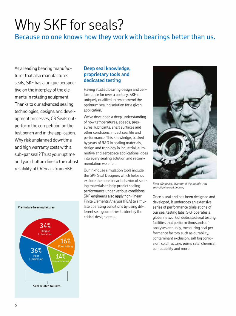
34%Fatigue
Lubrication
36%Poor
Lubrication14%
Contamination
16%Poor Fitting
Premature bearing failures
Seal related failures
Sven Wingquist, inventor of the double-row self-aligning ball bearing
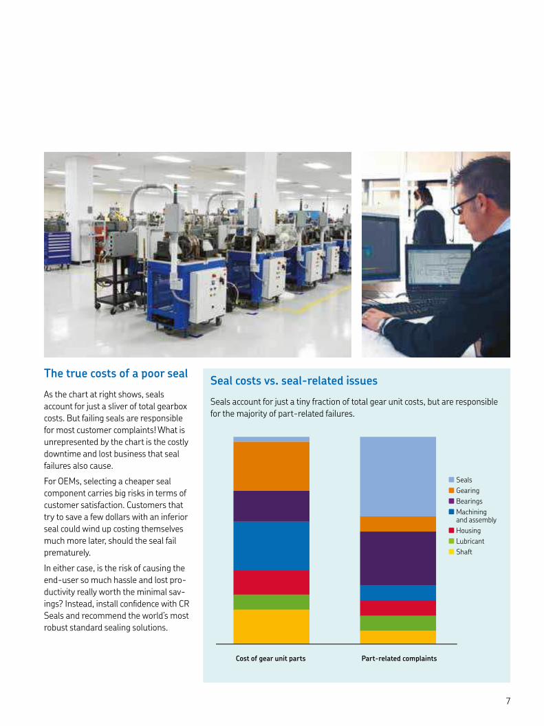
The true costs of a poor seal
As the chart at right shows, seals account for just a sliver of total gearbox costs. But failing seals are responsible for most customer complaints! What is unrepresented by the chart is the costly downtime and lost business that seal failures also cause.
For OEMs, selecting a cheaper seal component carries big risks in terms of customer satisfaction. Customers that try to save a few dollars with an inferior seal could wind up costing themselves much more later, should the seal fail prematurely.
In either case, is the risk of causing the end-user so much hassle and lost pro-ductivity really worth the minimal sav-ings? Instead, install confidence with CR Seals and recommend the world’s most robust standard sealing solutions.
n Seals
n Gearing
n Bearings
n Machining and assembly
n Housing
n Lubricant
n Shaft
Cost of gear unit parts Part-related complaints
Seal costs vs. seal-related issues
Seals account for just a tiny fraction of total gear unit costs, but are responsible for the majority of part-related failures.
CR Seals
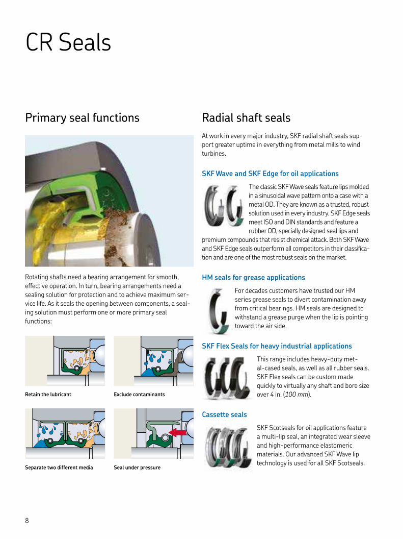
Primary seal functions
Rotating shafts need a bearing arrangement for smooth, effective operation. In turn, bearing arrangements need a sealing solution for protection and to achieve maximum ser-vice life. As it seals the opening between components, a seal-ing solution must perform one or more primary seal functions:
Radial shaft seals
At work in every major industry, SKF radial shaft seals sup-port greater uptime in everything from metal mills to wind turbines.
SKF Wave and SKF Edge for oil applications
The classic SKF Wave seals feature lips molded in a sinusoidal wave pattern onto a case with a metal OD. They are known as a trusted, robust solution used in every industry. SKF Edge seals meet ISO and DIN standards and feature a rubber OD, specially designed seal lips and
premium compounds that resist chemical attack. Both SKF Wave and SKF Edge seals outperform all competitors in their classifica-tion and are one of the most robust seals on the market.
HM seals for grease applications
For decades customers have trusted our HM series grease seals to divert contamination away from critical bearings. HM seals are designed to withstand a grease purge when the lip is pointing toward the air side.
SKF Flex Seals for heavy industrial applications
This range includes heavy-duty met-al-cased seals, as well as all rubber seals. SKF Flex seals can be custom made quickly to virtually any shaft and bore size over in. ( mm).
Cassette seals
SKF Scotseals for oil applications feature a multi-lip seal, an integrated wear sleeve and high-performance elastomeric materials. Our advanced SKF Wave lip technology is used for all SKF Scotseals.
Retain the lubricant
Separate two different media
Exclude contaminants
Seal under pressure

Axial shaft seals
Designed to seal axially against a counterface perpendicular to the shaft or pin, axial shaft seals from SKF include high performance primary seals plus cost-effective V-ring seals.
V-ring seals
V-ring seals from SKF offer an easy-to-install solution for rotating shaft applications, including use as a secondary seal in highly contaminated environments.
Metal faced seals
Originally designed for the low speeds and severe conditions that affect off-road and tracked vehicles, SKF metal face seals have proven equally suitable for applications exposed to sand, soil, mud, water and more.
Axial excluder seals
The CT axial seal is a split seal that can be clamped to a housing. The sealing lip runs on a rotating face and excludes contaminants. They can be cut to any size from in. ( mm) to over in. ( mm).
Wear sleeves
Over time, particles trapped underneath a shaft sealing lip form wear grooves on the shaft, leading to seal failure and shaft damage. SKF wear sleeves can help prevent the prob-lem, or correct it without re-machining the shaft.
SKF Speedi-Sleeve – Standard and Gold
SKF Speedi-Sleeve is a thin-walled shaft sleeve up to in. ( mm) that is pressed into position over the shaft to provide an excellent seal-ing surface, one that is superior to what can typically be achieved on a shaft.
LDSLV Wear sleeves
Designed for heavy industrial applica-tions, LDSLV wear sleeves accommo-
date shaft dimensions over in. ( mm) and are used on original equipment or to
repair the sealing surface of worn or damaged shafts.

CR Seals differentiators Rotary oil seals must pump to protect
To keep contaminants and mois-
ture from damaging a bearing or
shaft, a rotary shaft seal must
form a barrier between the oil
supply and the outside environ-
ment. But to perform as effec-
tively as possible, a seal must
also be able to pump oil away
from the air side and toward the
oil side. This “pump rate”
depends upon the seal lip design
and seal lip material – and CR
Seals is a global leader in pump
rate. How pump rate works
As figure indicates, the approach angle from the oil side of the seal lip is steeper than the air side. This difference creates a contact pressure curve biased toward the oil side, which affects the management of the thin film of oil between the lip and the shaft. When the shaft is in motion it wears surface fea-tures onto the rubber in a specific pattern.
These surface features, or asperities, behave much like the skin on the back of your hand. Undisturbed, the pores and wrinkles on your hand are fairly uniform and undistorted. But place a finger on your skin and tug, the pores and wrin-kles nearby will stretch as a reaction to the shear stress and orient themselves toward the direction of the forces.
Similarly, as a shaft rotates and wears the seal lip the surface asperities under the seal lip will form into a pattern that correlates with the pressure curve induced by the seal lip. This deformation is biased toward the oil side, just like the pressure curve from the lip.
As the arrows in figure indicate, the rotation of the shaft induces a hydrody-namic pumping mechanism that helps adjacent fluid molecules flow back toward the oil side at a surprising rate.
There are other ways to increase the pump rate of a seal, including adding hydrodynamic features like the SKF Wave or a helical pattern on the lip.
α β
Fig. Fig.
Oil side Air side
Air sideOil side
Seal lip
Rotating shaft
Oil side Air side
Undistorted seal lip surface structure at rest
Rotational friction distorts seal lip surface, creating torsional shear stress and forming a pattern of surface features call asperities
Overall effect of this pattern of asperities encourages oil to flow toward the oil side

Why pump rate matters
Simply put, the higher the pump rate, the more robust the sealing system. That’s because seals with a high pump rate will compensate for sealing system flaws that won’t appear in a controlled lab test.
On the test bench, even a seal that pumps poorly still forms a barrier between the oil and air chambers. How-ever, put that same seal in the field, and there are a range of potential sealing system flaws which can lead to failure. By simply keeping the oil on the side where it belongs, seals with a high pump rate will mitigate the effects of several uncon-trollable operating parameters.
CR Seals outpump the competition
To test pump rate, a fixed amount of oil is applied to the back side of the seal lip, then timed to see how long it takes for the oil to be pumped to the oil side. As diagram shows, SKF Wave seals delivered the highest pump rate of all major seal competitors. SKF Wave seals feature a patented sinusoidal lip design that enables the high pump rate, but even CR Seals with a conventional straight lip outpumped competitive seals. Bottom line? With the world’s most robust standard seal designs, CR Seals are more likely to work in any given application than any other standard seal, making them the best starting point for new designs or for problem solving.
High pump rates compensate for:
• Poor shaft surface finish
• Temperature swings
• Misalignment, runout and axial play
• Particle contamination
• Speed and pressure swings
• Shifting fluid viscosity
robustrō’bәstcapable of performing without failure
under a wide range of conditions
NBR FKM
180
160
140
120
100
80
60
40
20
0
Diagram
Relative pump rate
n SKF Wave n Competitor n Competitor n Competitor
% compared with SKF NBR

UNDER THE LIP, SKF WAVE SEALS RUN
°FCOOLER, REDUCING OIL AND
SEAL DEGRADATION
SKF Wave sealsThe most robust standard seals ever made
Since the s, the SKF Wave lip design has been protecting rotating equipment in the world’s harshest industrial environments. Time-tested in mines, mills, farms and other demanding places of work, SKF metal OD Wave seals feature a sinusoidal seal lip and advanced materials – a combination that helps SKF Wave seals out-pump and outlast any standard oil seal.
SKF Wave seal
• Pumps x more than standard seals
• Handles shaft misalignment
• Runs cooler with less drag
• Reduces shaft wear
• Cuts energy consumption
Typical applications
• Gearboxes
• Speed reducers
• Transmissions
• Motors
• Drive systems
• Pumps

1 0000 2 000 3 000 4 000 5 000
0
The SKF Wave lip
Industry’s highest pump rate
SKF metal OD Wave seals feature pat-ented SKF Wave lip design (†fig. ). As the shaft rotates beneath the wavy lip, the contact point itself moves back and forth across the shaft in a sinusoidal motion. This induces a hydrodynamic pumping action that pushes oil toward the bearing. The sinusoidal motion also distributes frictional heat over a wider wear band, reducing under lip operating temperature.
Less heat, friction and failure
Compared to conventional straight lip seals, SKF Wave seals generate up to % less heat and % less friction at the contact point († diagrams and ). Less heat and friction cuts equipment energy use, but it also means fewer heat-related seal failures. The % reduction in friction torque corresponds with a ˚F reduction in lip operating temperature, which could make the dif-ference between success and failure from overheated oil and a “cooked” seal lip.
Standard oil lips
More friction, less pumping
Unlike an SKF Wave lip seal, the contact point of a straight lip seal does not move back and forth across the shaft. Instead, contact is concentrated into a thin wear band († fig. ), increasing friction and under lip temperature as the shaft turns. Pumping capabilities, if any, depend solely on the lip angles and lip material.
Availability and options
INCH and METRIC sizes
Choose from thousands of SKF metal OD Wave seal sizes and styles – stocked, tooled and available fast.
SKF Bore Tite Coating
SKF metal OD Wave seal lips are available with SKF Bore Tite Coating – a non-hardening, water-based acrylic sealant that helps fill small imperfections in the housing bore.
Heavy duty options
For the heaviest-duty applications, SKF Wave seals are available with an auxiliary dust lip and/or an inner case.
Pressure seals
CRW Wave seals can handle pres-sures up to psi under normal conditions. For higher pressures up to psi we recommend the CRW and CRWA.
Temperature rise [°C (°F)] Frictional moment [Nm (ozf/in.)]
Speed [r/min] Speed [r/min]
1 0000 2 000 3 000 4 000 5 000
SKF Wave lip
SKF Wave lip
Conventional lipConventional lip
()
, () ()
, () ()
, () ()
, ()
()
()
Diagram
Temperature rise at sealing lip/counterface contact for conventional and SKF Wave lips as a function of rotational speed for a mm diameter shaft with SAE engine oil
Figure
Standard oil sealing lip with straight edge
Figure
SKF Wave sealing lip with sinusoidal sealing lip edge
Diagram
Frictional moment at sealing lip/counterface contact for conventional and SKF Wave lips as a function of rotational speed for a mm diameter shaft with SAE engine oil
oil side air sideoil side air side

SKF Edge HMS and HMSANot all straight lip seals are the same
SKF Edge shaft seals HMS and HMSA deliver a field-tested first line of defense against downtime. An SKF-developed nitrile rubber (NBR) compound and a spring-loaded sealing lip help SKF Edge seals handle aggressive lubricants, thermal expan-sion, high dynamic runout, shaft-to-bore misalignment or surface roughness. ISO and DIN -compliant, SKF Edge seals are more than suitable for the toughest industrial applications.
SKF Edge advantages
• Extend system service life
• Rubber OD seals better on bore
• Operate with synthetic oils
• x the pump rate of leading competitor
• Handle dynamic runout and shaft-to-bore misalignment
Typical applications
• Gearboxes
• Pumps
• Fans
• Axles
• Construction equipment
We’ve got you covered with over parts tooled and available in all configurations.

SKF Edge NBR
Radial lip load
NBR1 NBR2 NBR3 NBR4
0.3
0.2
0.1
0
60
40
20
0
NBR FKM
250
200
150
100
50
0
Diagram
Pump rate [μl/min] Radial load [N]
Diagram
Relative frictional torque
Higher pump rate
A recent independent study on seal pump rate pitted SKF Edge sealing tech-nology against several industry-leading seal products. Conducted at a major European university, the trial involved a standard test that measures seal pump rate.
Advanced lip design and materials development gave SKF the edge that helped the HMS seals outperform the field. The SKF Edge seal pumped at over three times the rate of a leading brand (NBR and ) and substantially outper-formed the others. († diagram )
Lower power consumption
In an SKF study, results showed the SKF HMS (RG) seal operates with % lower frictional torque on the shaft († diagram ). The SKF Edge seal’s lower radial lip load in diagram trans-lates into less frictional torque and power consumption shown in diagram – good for equipment and operators.
Handles misalignment
In a recent misalignment test against competitive seals, SKF Wave and SKF Edge were the only seals that could fol-low the shaft without leaking. The test featured a consecutive series of runout and misalignment iterations up to . in. (. mm) each – all non-SKF seal brands leaked well before the test reached those extremes.
Availability and options
Metric sizes
ISO and DIN compliant up to mm (. in.) shaft sizes
Spring
SKF Edge seals made with NBR (RG) material come with a carbon steel garter spring, while seals made with FKM (V) for higher surface speeds and temperatures carry a stainless steel spring. They come primarily in metric sizes and are surpris-ingly affordable, available and robust.
n SKF n Competitor n Low-cost competitor

TOOLING CHARGES FOR FLEX SEALS:
$
SKF Flex heavy industrial seals Made for work and made-to-order
In heavy industries, keeping lubricants in and contaminants out of systems is a seri-ous challenge. SKF Flex heavy industrial seals can handle the harshest application environments, and help speed and simplify installation.
SKF Flex heavy industrial seals
• Highly flexible design options
• Fast and simple installation reduces risk of failure and resulting downtime
• Unlimited size range, so not limited to listed handbook part numbers
• Improved sealing performance
• Configured and produced to your requirements
Typical applications
• Gearboxes
• Hot and cold rolling mills
• Paper mills
• Crushers
• General and specialized machinery
• Construction equipment
* Some special profiles may require minimal tool cost, but this is a rare exception
Extreme performance flexibility
In heavy industries, extreme sealing performance is just part of the job description. But depending on the application and jobsite, specific sealing challenges can vary greatly. Available in customizable metal-cased, all-rubber, or reinforced all-rubber designs, SKF Flex heavy industrial seals were designed to handle any sealing chal-lenge with as much flexibility as possible.
Full customization and fast delivery
SKF Flex seal orders need never be limited to the part numbers listed in this hand-book. Our flexible part numbering system (page ) allows for you to specify virtu-ally any size within the limits of table on page and receive parts in two to four weeks with no tooling charges (faster delivery options are available upon request).
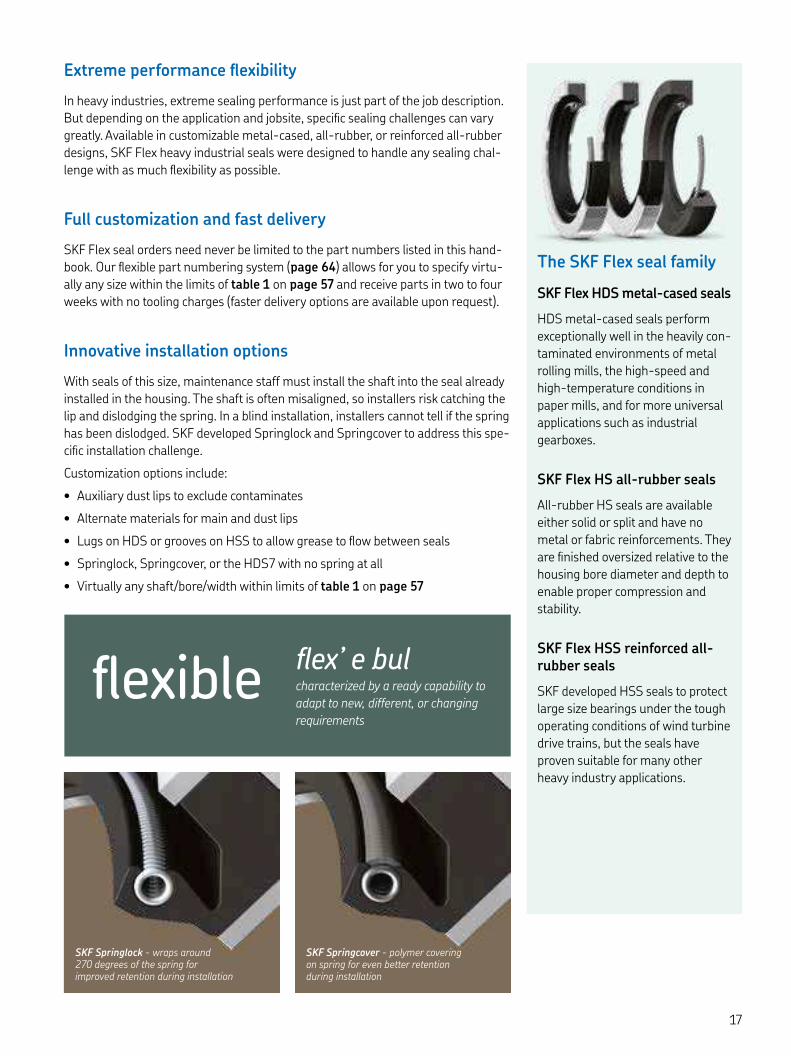
Innovative installation options
With seals of this size, maintenance staff must install the shaft into the seal already installed in the housing. The shaft is often misaligned, so installers risk catching the lip and dislodging the spring. In a blind installation, installers cannot tell if the spring has been dislodged. SKF developed Springlock and Springcover to address this spe-cific installation challenge.
Customization options include:
• Auxiliary dust lips to exclude contaminates
• Alternate materials for main and dust lips
• Lugs on HDS or grooves on HSS to allow grease to flow between seals
• Springlock, Springcover, or the HDS with no spring at all
• Virtually any shaft/bore/width within limits of table on page
The SKF Flex seal family
SKF Flex HDS metal-cased seals
HDS metal-cased seals perform exceptionally well in the heavily con-taminated environments of metal rolling mills, the high-speed and high-temperature conditions in paper mills, and for more universal applications such as industrial gearboxes.
SKF Flex HS all-rubber seals
All-rubber HS seals are available either solid or split and have no metal or fabric reinforcements. They are finished oversized relative to the housing bore diameter and depth to enable proper compression and stability.
SKF Flex HSS reinforced all-rubber seals
SKF developed HSS seals to protect large size bearings under the tough operating conditions of wind turbine drive trains, but the seals have proven suitable for many other heavy industry applications.
SKF Springlock - wraps around degrees of the spring for improved retention during installation
SKF Springcover - polymer covering on spring for even better retention during installation
flexible flex’ e bulcharacterized by a ready capability to
adapt to new, different, or changing
requirements

Scored
Restored
SAVE $ AND
weekOF REPAIR TIME
BE BACK UP AND RUNNING
IN AS LITTLE AS
minutes
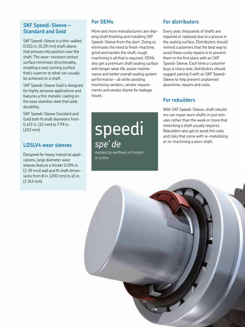
SKF Speedi-Sleeve wear sleeves The fastest way to an optimal sealing surface
Once a particle is trapped underneath a shaft sealing lip, it’s only a matter of time before the resulting shaft wear renders the seal ineffective. Repairs used to mean the costly, time-consuming proposition of shaft dismounting and re-machining. But SKF Speedi-Sleeve can take a shaft from scored to restored in just minutes – or eliminate the need to finish it in the first place.
SKF Speedi-Sleeve
• Increases productivity and reliability
• Improves sealing performance
• Minimizes downtime for repairs
• Eliminates shaft grinding, metalizing or machining
• Compatible with the original seal size
Typical applications
Virtually any with a radial shaft seal:
• Industrial gearboxes and transmissions
• Motors, speed reducers, pumps and fans
• Construction and agriculture equipment
• Crushers and conveyors
• Rolling mills and paper mills
SKF Speedi-Sleeve – Standard and Gold
SKF Speedi-Sleeve is a thin-walled . in. (. mm) shaft sleeve that presses into position over the shaft. The wear-resistant contact surface minimizes directionality, enabling a seal running surface that’s superior to what can usually be achieved on a shaft.
SKF Speedi-Sleeve Gold is designed for highly abrasive applications and features a thin metallic coating on the base stainless steel that adds durability.
SKF Speedi-Sleeve Standard and Gold both fit shaft diameters from . in. ( mm) to . in. ( mm).
LDSLV wear sleeves
Designed for heavy industrial appli-cations, large diameter wear sleeves feature a thicker . in. (. mm) wall and fit shaft dimen-sions from in. ( mm) to in. ( mm).
For OEMs
More and more manufacturers are skip-ping shaft finishing and installing SKF Speedi-Sleeve from the start. Doing so eliminates the need to finish-machine, grind and harden the shaft; rough machining is all that is required. OEMs also get a premium shaft sealing surface with longer wear life, easier mainte-nance and better overall sealing system performance – all while avoiding machining vendors, vendor require-ments and vendor blame for leakage issues.
For distributors
Every year, thousands of shafts are repaired or replaced due to a groove in the sealing surface. Distributors should remind customers that the best way to avoid these costly repairs is to prevent them in the first place with an SKF Speedi-Sleeve. Each time a customer buys a rotary seal, distributors should suggest pairing it with an SKF Speedi-Sleeve to help prevent unplanned downtime, repairs and costs.
For rebuilders
With SKF Speedi-Sleeve, shaft rebuild-ers can repair worn shafts in just min-utes rather than the week or more that reworking a shaft usually requires. Rebuilders also get to avoid the costs and risks that come with re-metallizing or re-machining a worn shaft.
speedispe’ demarked by swiftness of motion
or action

SKF Speedi-Sleeve wear sleevesThe fastest way to an optimal sealing surface
Less abrasion and wear, more reliability
After the -hour contamination test († diagram ), the latest generation SKF Speedi-Sleeve reduced abrasion by a factor of , vs. the previous version and was still operating efficiently. In the hour life test shown in diagram , the latest generation SKF Speedi-Sleeve reduced sealing lip wear and the variation in the wear rate by approximately % com-pared to the previous generation and outperformed a chromi-um-plated surface by a factor of .
The new generation SKF Speedi-Sleeve wears less than
standard sleeves and increases overall sealing system
performance.
New generation design and performance
Reflecting our commitment to continuous design improve-ments, the new generation SKF Speedi-Sleeve feature a pro-prietary stainless steel material and a manufacturing process that increases strength and ductility. The result is an opti-mized seal counterface surface that wears less than standard sleeves and increases overall sealing system performance.
Putting SKF Speedi-Sleeve to the test
In an effort to continuously improve our design, SKF has introduced an even better Speedi-Sleeve; a new generation of performance. SKF compared the new generation SKF Speedi-Sleeve with the previous generation in a series of abrasion wear tests. First, both Speedi-Sleeve generations were measured for abrasion resistance after exposure to coarse and fine dust conditions. A second test with both generations measured sealing lip abrasion resistance using SKF Wave seals made from the SKF FKM material SKF Duralife. Operat-ing conditions were the same for each test: temperatures up to °F ( °C) and linear shaft speeds of up to ft/min (, m/s).
Diagram
SKF Speedi-Sleeve wear testAbrasive media, test stopped at hours
Sleeve wear [- mm]
100
0
80
60
40
20
New generation SKF Speedi-Sleeve
Variation20
0
5
10
15
Average
Previous generation SKF Speedi-Sleeve
Diagram
Sealing lip wear testSeals made from FKM, test stopped at hours
Sleeve lip wear [- mm]
Variation Average
Chromium- plated surface
New generation SKF Speedi-Sleeve
Previous generation SKF Speedi-Sleeve

Chromium-plated sleeve A
Chromium-plated sleeve B
New generation SKF Speedi-Sleeve
A closer look at sleeve sealing surfaces
Images from a scanning electron micro-scope (SEM) show the razor sharp micro-cracks that often form on the chrome-plated surface of a thin sleeve.
Chromium isn’t all it’s cracked up to be
As diagram shows, chromium-plated shaft repair sleeves cause seals to wear out more quickly than SKF Speedi-Sleeve. Although chromium-plating renders a harder surface than stainless steel, once it is applied to a paper-thin substrate it will invariably crack, as the SEM images reveal. These razor-sharp micro-cracks significantly shorten seal life. SKF found this risk in the s, yet chrome plating is still found in the mar-ket and touted for extreme wear resist-ance. Try SKF Speedi-Sleeve Gold - the proven solution for dirty, abrasive applications.

SKF Speedi-Sleeve wear sleeves General installation/removal instructions
Installing SKF Speedi-Sleeve
Clean the seal counterface surface on the shaft. File down any burrs or rough spots and DO NOT install the sleeve over keyways, cross holes, splines or similar obstructions.
Measure shaft diameter on an unworn position where the sleeve will be positioned († fig. ). Measure in three positions and average the readings to make sure the shaft is within recommended specifications. If the average diameter is within the range for a given sleeve size, there is sufficient press fit built into the sleeve to prevent it from sliding or spinning without using an adhesive.
Determine where the sleeve must be positioned to cover the worn area. Measure to the exact point and mark with a marker directly on the surface. The sleeve must be placed over the worn area, not just bottomed or left flush with the end of the shaft.
Shallow wear grooves do not require filling. Optionally, a light layer of a non-hardening sealant can be applied to the inside diameter sur-face of the sleeve. Clean away sealant that migrates to the shaft or sleeve outside diameter surface.
If the shaft is deeply scored, fill the groove with a powdered metal epoxy-type filler. Install the sleeve before the filler hardens, enabling the sleeve to expel any excess filler. Clean away any remaining filler from the sleeve outside diameter surface.
Never use heat to install SKF Speedi-Sleeve.
If the flange requires removal after installation, cut it from the outside diameter into the radius in one loca-tion. The flange end of the sleeve goes on the shaft first, followed by the installation tool over the sleeve († fig. ).
Gently tap the center of the installa-tion tool until the sleeve covers the worn shaft surface († fig. ). If the installation tool is too short, a length of pipe or tubing with a squared-off, burr-free end can also be used. Make sure that the inside diameter of the pipe matches that of the installa-tion tool. Use care not to scratch the precision ground sleeve’s outside diameter.
SKF Speedi-Sleeve should always be installed so that the outside edge of the sleeve is seated on the full shaft diameter. It must not rest in or out-side the chamfer area as the sharp edge will likely cut the sealing lip during seal installation.
If the flange was cut for removal, grasp the flange with a pair of long-nosed pliers to pull it away from the sleeve. Twist it into a coil to remove it fully; DO NOT lift the end of the sleeve off the shaft as it will leave a jagged edge. Flange removal must be done with care to avoid damage to the outside diameter of the sleeve.
After the sleeve is installed, check again for burrs that could damage the seal.
Lubricate the sleeve with the system medium before installing the seal.
Proceed with seal installation.
SKF Speedi-Sleeve requires
proper installation and removal
to function optimally. Follow the
steps listed to ensure SKF
Speedi-Sleeve is installed and
removed effectively.

Removing SKF Speedi-Sleeve
SKF Speedi-Sleeve can be removed by applying heat to the sleeve with an elec-tric heat blower. The heat will expand the sleeve enough to let it slide off eas-ily, without damaging the shaft. The sleeve can also be removed without heat by:
– relieving the press-fit tension using a small hammer to peen across the full width of the sleeve
– using a cold chisel to cut through the sleeve
– using a pair of wire cutters starting at or near the flange and applying a twisting motion
Always use care to avoid damaging
the shaft surface during any removal
procedure. Please note that SKF
Speedi-Sleeve cannot be reused.
Using LDSLV designs
SKF LDSLV wear sleeves for heavy industrial applications can be used in two ways († fig. ):
Position the sleeve on the shaft until it covers the damaged part. Use a new seal, designed for a . in. (. mm) larger shaft diameter.
Machine the shaft down by . in. (. mm) in diameter, then install it w/original seal size. The reworked shaft surface for the sleeve should have a surface roughness between Ra . and . μm ( to μin.). Suitable for use in systems with sus-tained temperatures higher than °F ( °C) and surface speeds in excess of , ft/min ( m/s).
Installing LDSLV
SKF wear sleeves for heavy industrial applications are designed for a heated slip-fit installation and must therefore be uniformly heated prior to installation. The sleeve temperature should be approximately °F ( °C). Under no circumstances should the sleeve be heated to above °F ( °C ).
Heating techniques normally used for bearings are suitable, such as induction heaters or heating cabinets. Sleeves should be installed immediately after heating as they cool rapidly and could seize on the shaft before the correct position is achieved. If repositioning is necessary, use a soft-faced hammer and a wooden block. After the sleeve is in the desired position, check the lead-in chamfer for any damage from installation.
Removing LDSLV
The wear sleeves can be removed either by heating them or expanding them by light hammer blows.
Figure
Figure
Figure
Figure
Using LDSLV designs
Alternative
Original shaftAlternative
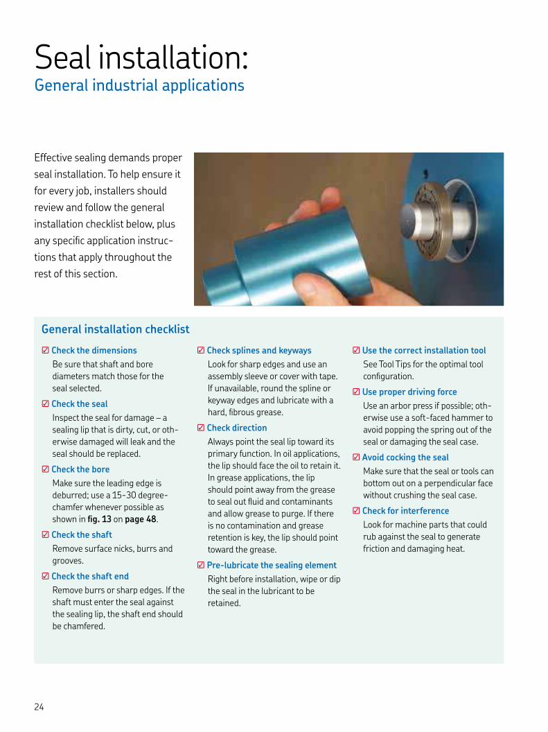
Seal installation:General industrial applications
Effective sealing demands proper
seal installation. To help ensure it
for every job, installers should
review and follow the general
installation checklist below, plus
any specific application instruc-
tions that apply throughout the
rest of this section.
General installation checklist
☑ Check the dimensions
Be sure that shaft and bore diameters match those for the seal selected.
☑ Check the seal
Inspect the seal for damage – a sealing lip that is dirty, cut, or oth-erwise damaged will leak and the seal should be replaced.
☑ Check the bore
Make sure the leading edge is deburred; use a - degree-chamfer whenever possible as shown in fig. on page .
☑ Check the shaft
Remove surface nicks, burrs and grooves.
☑ Check the shaft end
Remove burrs or sharp edges. If the shaft must enter the seal against the sealing lip, the shaft end should be chamfered.
☑ Check splines and keyways
Look for sharp edges and use an assembly sleeve or cover with tape. If unavailable, round the spline or keyway edges and lubricate with a hard, fibrous grease.
☑ Check direction
Always point the seal lip toward its primary function. In oil applications, the lip should face the oil to retain it. In grease applications, the lip should point away from the grease to seal out fluid and contaminants and allow grease to purge. If there is no contamination and grease retention is key, the lip should point toward the grease.
☑ Pre-lubricate the sealing element
Right before installation, wipe or dip the seal in the lubricant to be retained.
☑ Use the correct installation tool
See Tool Tips for the optimal tool configuration.
☑ Use proper driving force
Use an arbor press if possible; oth-erwise use a soft-faced hammer to avoid popping the spring out of the seal or damaging the seal case.
☑ Avoid cocking the seal
Make sure that the seal or tools can bottom out on a perpendicular face without crushing the seal case.
☑ Check for interference
Look for machine parts that could rub against the seal to generate friction and damaging heat.
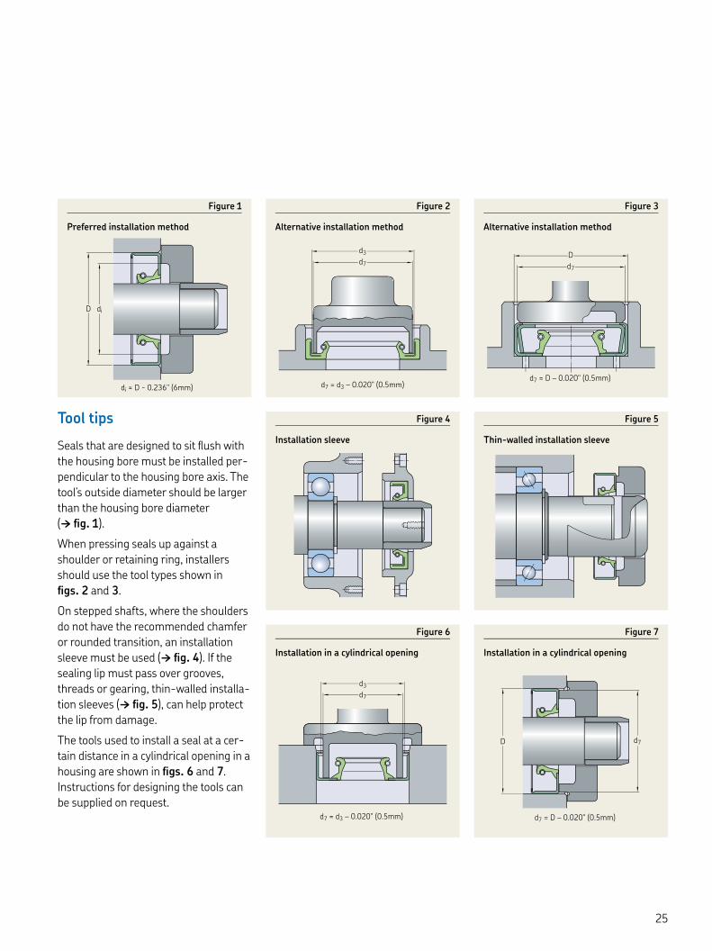
Tool tips
Seals that are designed to sit flush with the housing bore must be installed per-pendicular to the housing bore axis. The tool’s outside diameter should be larger than the housing bore diameter († fig. ).
When pressing seals up against a shoulder or retaining ring, installers should use the tool types shown in figs. and .
On stepped shafts, where the shoulders do not have the recommended chamfer or rounded transition, an installation sleeve must be used († fig. ). If the sealing lip must pass over grooves, threads or gearing, thin-walled installa-tion sleeves († fig. ), can help protect the lip from damage.
The tools used to install a seal at a cer-tain distance in a cylindrical opening in a housing are shown in figs. and . Instructions for designing the tools can be supplied on request.
di ≈ D - 0.236" (6mm)
D di
d7
d7 = d3 – 0.020" (0.5mm)
d3
d7 = D – 0.020" (0.5mm)
d7
D
d7
d3
d7 = d3 – 0.020" (0.5mm) d7 = D – 0.020" (0.5mm)
D d7
Figure
Preferred installation method
Figure
Installation sleeve
Figure
Alternative installation method
Figure
Thin-walled installation sleeve
Figure
Alternative installation method
Figure
Installation in a cylindrical opening
Figure
Installation in a cylindrical opening

Seal installation:SKF Flex heavy industrial applications
Metal-reinforced seals
When installing metal-reinforced seals, first check the shaft and housing bore for proper specifications and condition. Next, coat both the seal and bore lightly with a lubricant, preferably the same one that will lubricate the application. For large diameter seals, a special installation tool may not be practical. In such cases, do not hit the seal or seal case directly; instead, use a wooden block long enough to span the seal’s outside diameter.
When using this method, it is important to apply hammer-blows evenly and sequentially to the wood piece around the seal circumference to prevent the seal from tilting or skewing. SKF also recommends the use of a dead blow hammer for full energy transfer with less impact († fig. ).
In some applications, the housing is designed for two seals in tandem, or a seal might have to be recessed further into the bore depth. In those cases, first set the seal flush with the housing using the method described above. Then, use a shorter piece of wood to drive the seal deeper into the bore utilizing a sequen-tial pattern († fig. ).
Seals without metal reinforcement
Be sure that the shaft surface and housing bore are clean and that they meet the specifications listed in Shaft requirements and Housing bore requirements on pages -. Special care must be taken to avoid nicks and burrs on the shaft and to make sure that the spring is retained in the spring groove.
HS and HSS seals are installed differ-ently depending on whether their main purpose in a specific application is to retain lubricant or to exclude contami-nants († fig. ).
12
3
4
5
67
8
Figure
Installation deeper into the bore
1 2
3
4
5
6 7
8
Figure
Use a dead blow hammer
Split seals
Where appropriate, insert the spring in the SKF Springlock groove and position the spring connection, so that it is dis-placed with regard to the seal joint († A in fig. ). This is standard with all HS seals. Put the seal in the correct position on the shaft.
Lightly coat both the seal and counter-face surface with a lubricant, preferably the same lubricant that will lubricate the application (B).
Join the ends of the garter spring using the spring connector (C).
For threaded connectors, back-wind the spring a couple of turns before the ends are brought together and allowed to thread into each other. When using a hook-and-eye connector, draw the ends of the spring together and insert the hook into the eye, taking care not to over-stretch the spring in the process, as this might impair seal performance. When using a control-wire connector, draw the seal ends together and insert the control wire into the center of the spring coil.

Position the seal joint on the shaft at the o’clock position and push both ends of the joint into the housing bore (D). Do not push only one joint and then work around the shaft as this will create an excess length, making installation diffi-cult or impossible.
Continue at the and o’clock posi-tions; push the rest of the seal into posi-tion (E) and finish simultaneously at the and o’clock positions. For shaft diameters ≥ in. ( mm), fix the seal at the , , and o’clock posi-tions before locating the remaining sec-tions of the seal.
Use a small block of wood to push the seal in the housing bore until it contacts the housing shoulder (E).
Check the seal condition, particularly at the joint, to make sure that it has been positioned properly.
Install the cover plate (see paragraph Cover plates on page ) on the housing face. Tighten the bolts evenly until the end cover abuts the housing face (F and G).
Figure
Installing a split seal
Figure
Ways of installing HS seals
HS seals in tandem arrangement for maxi-mum lubricant retention
HS seal installed to exclude foreign material
HS seal installed to retain lubricant
A E
F
B
C
D G

Seal installation:SKF Flex Heavy industrial applications
Cover plates
Seals without metal reinforcement, split and solid, are manufactured oversized relative to the housing bore diameter and depth to enable proper compression and stability. A cover plate († fig. ) provides axial compression of the seal and stabi-lizes it in the housing bore to achieve maximum seal performance. The cover plate must be dimensioned properly to obtain the required fit. It should be thick enough not to bend or distort; generally, a thickness of . to . in. (. to . mm) is sufficient.
The plate should be fastened with bolts, no more than in. ( mm) apart, on a bolt circle located as close to the seal housing bore as practical. The cover plate should be flat and the housing bore depth uniform. Splitting the cover plate at ° will make seal replacement eas-ier, particularly in confined areas.
To block surges of lubricant toward the seal from the inside and to protect the seal from damage from the outside, SKF
recommends dimensioning the inside diameter of the cover plate so that it is . to . in. ( to mm) greater than the shaft diameter to accommo-date shaft-to-bore misalignment and runout († fig. ).
In applications where supplementary sealing is necessary and it is impractical to machine the original housing to pro-vide a seal cavity, a seal cavity can be incorporated into a new plate that is bolted into place as in fig. .
Bore depth and seal width
For all rubber HS and HSS seals, the seal width is approximately . in. to . in. (. to . mm) wider than the bore depth B († fig. ). For sizing pur-poses, the bore depth and nominal seal width are the same. Therefore, when building a part number according to the SKF Flex designation system (page ), you should put the bore depth (nominal seal width) in the part number.
N
P D
B
D1 d1
6,35 – 12,7 mm
Figure
Cover plate recommendations
Figure
Cover plate
Figure
Spacing washer
Inside diameter of cover: D ≈ d + .. [mm]
Pitch circle diameter of screws: P ≈ , D [mm]
No. of attachment screws: N ≈ , P
Bore depth = Nominal seal width = B
New seal cavity plate
Seal-retaining cover plate
Sealing element
For example, the “” in a -- HSS R calls out a nominal /-inch width, which fits properly in a /-inch bore depth. We make the seal slightly wider than that so the cover plate will close tightly on the seal for stability. This principle only applies to all rubber HS and HSS seals; metal cased seals are made to the target width called out in the part number. For HS seals, the bore depth tolerance should be °æ. in. (. mm) and °æ. in. (. mm) for all-rubber reinforced HSS seals.

Multiple HS seal installations
When installing two split all-rubber HS seals in one cavity, the locations of the split joints should be staggered by ° to ° to minimize the risk of leakage through the joints. The splits should be located toward the top of the bore. Grease the cavity between the seals to provide lubricant to the outer sealing lip.
When two HS seals, split or solid, are installed in the same housing bore, a spacing washer must be placed between the two seals († fig. ). Suit-able washer dimensions can be deter-mine based on the shaft and housing bore diameters, d and D, respectively:
washer inside diameter
= d + . to . in. ( to mm)
washer outside diameter
= D – . to . in. (. to . mm)
The width of the washer is determined by the application conditions. There should, however, always be sufficient room for lubrication holes to be pro-vided in the circumference, or lubrica-tion grooves in one side face († fig. ). These lubrication provisions must ena-ble grease to be supplied from the housing to the sealing lips via a drilled passage or grease fitting († fig. ). When determining what washer width is appropriate for the depth of a housing bore, it is necessary to consider the axial displacement required when clamping the seals.
Figure
Details of spacing washer for central lubricationA separator between two seals can be a slotted washer to promote distribution of the lubricant.
d + . in. (d + , mm)
D – . in. (D – ,/, mm)
Figure
Spacing washer and grease fitting
Figure
Spacer lug
Multiple HDS seal installations
When installing two metal-cased radial shaft seals in the same housing bore, either in a tandem or back-to-back arrangement, care must be taken that neither of the sealing lips run dry. To reduce the risk of dry running, the space between the seals should be filled with a suitable grease.
SKF also recommends using spacer lugs or a spacing washer between the two seals. The spacing washer should be provided with lubrication holes so that grease can be supplied to the space between the sealing lips via a grease fitting († fig. ). No spacing washer is required when using seals that have spacer lugs built into the air side of the metal case († fig. ).
Seal installation:Special considerations for a PTFE lip
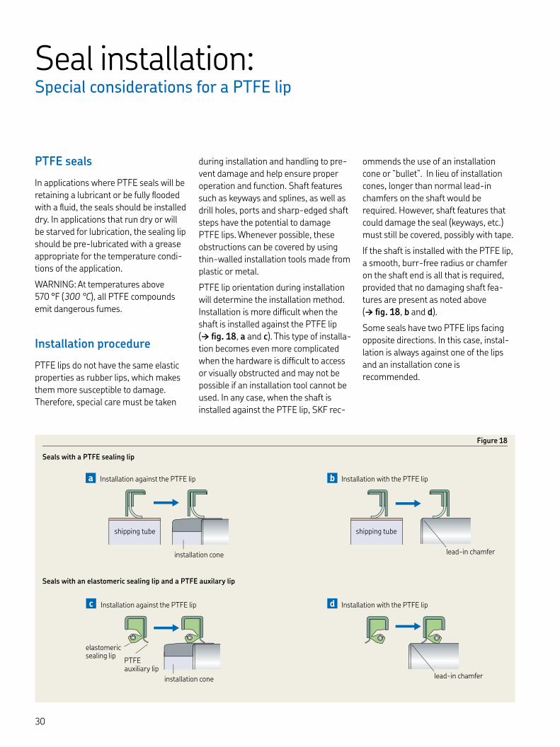
PTFE seals
In applications where PTFE seals will be retaining a lubricant or be fully flooded with a fluid, the seals should be installed dry. In applications that run dry or will be starved for lubrication, the sealing lip should be pre-lubricated with a grease appropriate for the temperature condi-tions of the application.
WARNING: At temperatures above °F ( °C), all PTFE compounds emit dangerous fumes.
Installation procedure
PTFE lips do not have the same elastic properties as rubber lips, which makes them more susceptible to damage. Therefore, special care must be taken
during installation and handling to pre-vent damage and help ensure proper operation and function. Shaft features such as keyways and splines, as well as drill holes, ports and sharp-edged shaft steps have the potential to damage PTFE lips. Whenever possible, these obstructions can be covered by using thin-walled installation tools made from plastic or metal.
PTFE lip orientation during installation will determine the installation method. Installation is more difficult when the shaft is installed against the PTFE lip († fig. , a and c). This type of installa-tion becomes even more complicated when the hardware is difficult to access or visually obstructed and may not be possible if an installation tool cannot be used. In any case, when the shaft is installed against the PTFE lip, SKF rec-
ommends the use of an installation cone or “bullet”. In lieu of installation cones, longer than normal lead-in chamfers on the shaft would be required. However, shaft features that could damage the seal (keyways, etc.) must still be covered, possibly with tape.
If the shaft is installed with the PTFE lip, a smooth, burr-free radius or chamfer on the shaft end is all that is required, provided that no damaging shaft fea-tures are present as noted above († fig. , b and d).
Some seals have two PTFE lips facing opposite directions. In this case, instal-lation is always against one of the lips and an installation cone is recommended.
Seals with an elastomeric sealing lip and a PTFE auxilary lip
Figure
Seals with a PTFE sealing lip
shipping tube
lead-in chamfer
Installation with the PTFE lipb
lead-in chamfer
Installation with the PTFE lipd
installation cone
elastomeric sealing lip
PTFE auxiliary lip
Installation against the PTFE lipc
shipping tube
Installation against the PTFE lipa
installation cone

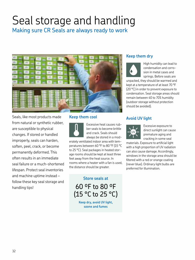
Seal storage and handlingMaking sure CR Seals are always ready to work
Seals, like most products made
from natural or synthetic rubber,
are susceptible to physical
changes. If stored or handled
improperly, seals can harden,
soften, peel, crack, or become
permanently deformed. This
often results in an immediate
seal failure or a much-shortened
lifespan. Protect seal inventories
and machine uptime instead –
follow these key seal storage and
handling tips!
Keep them cool
Excessive heat causes rub-ber seals to become brittle and crack. Seals should always be stored in a mod-
erately ventilated indoor area with tem-peratures between °F to °F ( °C to °C). Seal packages in heated stor-age rooms should be kept at least three feet away from the heat source. In rooms where a heater with a fan is used, the distance should be greater.
Keep them dry
High humidity can lead to condensation and corro-sion in metal cases and springs. Before seals are
unpacked, they should be warmed and kept at a temperature of at least °F ( °C) in order to prevent exposure to condensation. Seal storage areas should remain between to % humidity (outdoor storage without protection should be avoided).
Avoid UV light
Excessive exposure to direct sunlight can cause premature aging and cracking in some seal
materials. Exposure to artificial light with a high proportion of UV radiation can also cause damage. Accordingly, windows in the storage area should be filtered with a red or orange coating (never blue). Ordinary light bulbs are preferred for illumination.
Store seals at
ºF to ºF ( °C to °C)
Keep dry, avoid UV light,
ozone and fumes

Avoid ozone and fumes
Seals should be stored away from ozone-emitting sources such as fluorescent lights, mercury lights, or
electric motors. Because combustion fumes and vapors can produce ozone as the result of photochemical processes, all solvents, fuels, lubricants, chemicals, acids, disinfectants, etc. should not be stored in the same room as seals.
Don’t leave them hanging
In many facilities, seals hang on maintenance shop walls next to belts and chains. But hanging a seal
on a nail or any small surface for more than a few hours will permanently dis-tort the lip, creating a leak path that eventually can lead to seal failure. In general, elastomer products should not be subjected to any tension or compres-sion during storage.
Keep in package until use
A seal should remain in its original packaging until it’s time for installation. Once a seal leaves the box, it can
be compromised easily by rough han-dling, contaminants and environmental conditions. SKF seal package labeling conveys key information about the seal inside, so there’s no need to open the box. Instead, keep it closed and keep the seal factory-new for installation.
Hands off the sealing lip
Once the box is open, remember to NEVER han-dle a seal by the lip. Seal lips can be as thin as .
mm, and simply touching or grabbing them can create momentary depres-sions. Such depressions can bounce back into shape, or they can lead to per-manent crimps and tears and ultimately, seal failure. Natural oils in your hands can weaken certain seal materials as well.
Keep them contaminant-free
Never place a seal on a dirty workspace area. The RTV, metal chips, dirt and dust they can pick up will
eventually undermine bearing perfor-mance. Be particularly careful with a seal that has just been lubricated for installation, as lubricant attracts con-taminants like a magnet.
Avoid contact with certain metals
Certain metals, especially copper and manganese, damage elastomer products.
Contact with these metals should there-fore be avoided and the seals should be covered with layers of paper or polyeth-ylene to prevent such contact.
SKF seal storage and guidelines meet ISO and DIN standards

CR Seals lip materials Optimized material options for industrial applications
Wear resistance
Seal wear resistance depends largely on the sealing lip material, although shaft surface finish, lubricant type, circumfer-ential speed, temperature, and pressure differentials all play a role. Diagram compares relative wear resistance for CR Seals lip materials when the seals are of the same size and operating under identical conditions.
Operating temperatures
At low temperatures, the sealing lip loses its elasticity and becomes hard and brittle. Sealing efficiency decreases and the seal becomes more susceptible to mechanical damage. At high temper-atures, the lubricant film often breaks down, resulting in insufficient lubrica-tion – one of the most common causes of premature seal failure.
Diagram presents the permissible operating temperature ranges of key SKF sealing lip materials.
To keep up with ever-changing sealing demands, SKF is constantly
developing high-performance sealing solutions from these key mate-
rial types:
NBR
Acrylonitrile-butadiene rubber (nitrile or Buna N) materials are extremely flex-ible; many resist mineral oils, greases and more.
XNBR (SKF Duralip)
This SKF-developed carboxylated nitrile rubber combines good technical prop-erties of nitrile rubber with increased wear resistance.
HNBR (SKF Duratemp)
This SKF-developed hydrogenated nitrile rubber can withstand abrasive environments and high temperatures.
FKM (SKF Duralife)
This SKF-developed fluorocarbon rub-ber compound offers excellent resist-ance to wear, chemicals, UV light and ozone.
PTFE
Polytetrafluoroethylene compounds withstand aggressive chemicals, high temperatures and pressures and dry running conditions.
Polyacrylate elastomer
Polyacrylate elastomers are more heat-resistant than nitrile rubber or SKF Duralip, and resist aging and ozone.
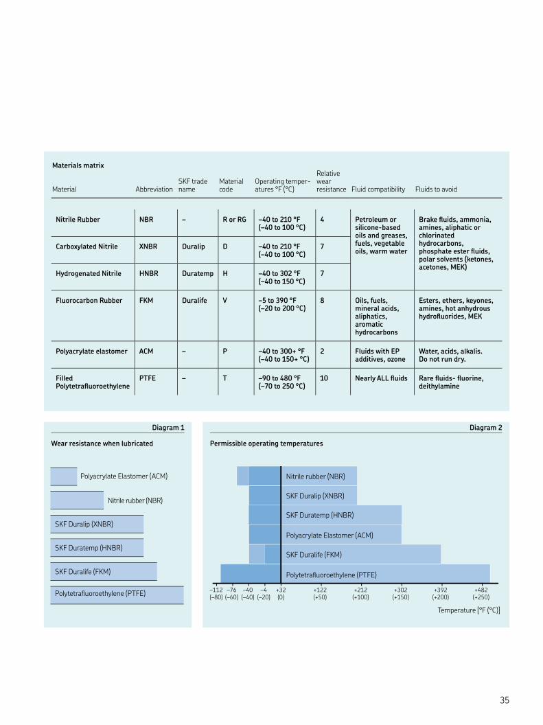
Materials matrix Material
Abbreviation
SKF trade name
Material code
Operating temper-atures °F (°C)
Relative wear resistance Fluid compatibility
Fluids to avoid
Nitrile Rubber NBR – R or RG – to °F (– to °C)
Petroleum or silicone-based oils and greases, fuels, vegetable oils, warm water
Brake fluids, ammonia, amines, aliphatic or chlorinated hydrocarbons, phosphate ester fluids, polar solvents (ketones, acetones, MEK)
Carboxylated Nitrile XNBR Duralip D – to °F (– to °C)
Hydrogenated Nitrile HNBR Duratemp H – to °F (– to °C)
Fluorocarbon Rubber FKM Duralife V – to °F (– to °C)
Oils, fuels, mineral acids, aliphatics, aromatic hydrocarbons
Esters, ethers, keyones, amines, hot anhydrous hydrofluorides, MEK
Polyacrylate elastomer ACM – P – to + °F (– to + °C)
Fluids with EP additives, ozone
Water, acids, alkalis. Do not run dry.
Filled Polytetrafluoroethylene
PTFE – T – to °F (– to °C)
Nearly ALL fluids Rare fluids- fluorine, deithylamine
Nitrile rubber (NBR)
SKF Duralip (XNBR)
SKF Duratemp (HNBR)
SKF Duralife (FKM)
Polyacrylate Elastomer (ACM)
Polytetrafluoroethylene (PTFE)
Diagram
Wear resistance when lubricated
Diagram
Permissible operating temperatures
+32 +122 +212 +302 +392 +482–4–40–76–112(0) (+50) (+100) (+150) (+200) (+250)(–20)(–40)(–60)(–80)
Nitrile rubber (NBR)
SKF Duralip (XNBR)
SKF Duratemp (HNBR)
Polyacrylate Elastomer (ACM)
SKF Duralife (FKM)
Polytetrafluoroethylene (PTFE)
Temperature [°F (°C)]

CR Seals lip materials Optimized material options for industrial applications
Chemical and thermal resistance
Chemical resistance to the medium to be sealed or excluded is the most important factor when selecting an elastomer for a radial shaft seal. Oper-ating temperature is a close second, however, as heat accelerates aging of the elastomer and increases the reac-tivity and aggressiveness of the sealed medium.
Guideline values are provided in table for the operating temperatures at which SKF seals will remain chemically resist-ant. The temperature range stated for a group of media means that the sealing
material is resistant when continuously operated within this particular range.
The N means that, within the group, there are some media that are compati-ble with the elastomer, but also some that have a detrimental effect on the elastomer. The n means that the seal material is not resistant to media belonging to this group.
A seal’s chemical resistance is influenced by temperature, pressure and the amount of media present. Table (page in the Appendix) provides information regarding the resistance of SKF sealing lip materials to most sub-
stances encountered in industrial applications.
The information is based on in-house testing plus input from seal end-users and suppliers of the various materials. Unless otherwise stated, the informa-tion is valid for media of commercial purity and quality. As seal service life can be influenced by all of the factors noted above, the information contained in table should only be considered as a rough guide.
Table
Chemical and thermal resistance, radial shaft seal lip materials
Medium to be sealed Permissible operating temperatures (continuous) for SKF radial shaft seal lip materials
R P V(NBR) (ACM) (FKM)
– °F °C °F °C °F °C
Mineral oil based lubricantsMotor oils Gear oils Hypoid gear oils Automatic transmission fluids (ATF oils) Greases N N
Hydraulic fluids
Fire-resistant hydraulic fluidsOil in water emulsions and aqueous polymer solutions
n N
Anhydrous fluids n n
Other mediaFuel oils EL and L N N
Water n Alkaline washing solutions n
Permissible temperature range for sealing lip min: – – – – – –
max: + + + + + +
n Lip material not resistant N Lip material not resistant to some media in this group

Seal cases and inserts
Metal cases and reinforcements for SKF radial shaft seals are manufactured standard from deep-drawn carbon sheet steel. The exposed surfaces are treated to protect them from corrosion during normal handling and storage. SKF radial shaft seals that will be used in corrosive environments can also be designed with a stainless steel case on request.
Garter springs
The garter springs on SKF radial shaft seals are manufactured standard from cold-drawn steel wire. Exceptions are the metal-cased HDS seals, the all-rub-ber HS seals, and the HMS/HMSA seals made from fluoro rubber that are designed with stainless steel garter springs.
SKF Bore Tite Coating
Available on most SKF metal-cased seals, SKF Bore Tite Coating is a water-based acrylic sealant used as a coating on the outside diameter of the seal. SKF Bore Tite Coating is pliable with a thick-ness of . to . in. (. to . mm ) to compensate for small imperfections in the housing bore surface.
The general guideline in Rubber Manu-facturers Association (RMA) is, that if the bore surface texture is greater than μin. (. μm) Ra, a sealant should be used. This sealant can be used at temperatures up to °F ( °C) and is compatible with most oils, greases, aqueous acids and alkalis, alcohols and glycols. While SKF Bore Tite Coating is not compatible with aromatics, ketones or esters, contact with these substances will have little or no effect if wiped off quickly.
Adhesives and bonding agents
Adhesives and bonding agents are used to achieve static sealing ability and sat-isfactory bonding between metal and elastomers in seal designs. Both of them can be solvent or water-based depending on the metal and elastomer to be bonded.
CR Seal with green SKF Bore Tite Coating
EngineeringConfigurations
Selecting a seal design and material
Choosing the optimum seal design and material depends on the operating con-ditions of the application, including:
• Temperature
• Speed
• Pressure differential
• Lubricant type
• Vertical or horizontal orientation
• Runout and shaft-to-bore misalignment
Because the influence of one operating condition typically dominates the seal selection process, there are no universal rules for determining the most appro-priate seal type or design for a given application. Instead, this section pro-vides general seal selection guidelines by describing how operating conditions affect seal performance and service life.
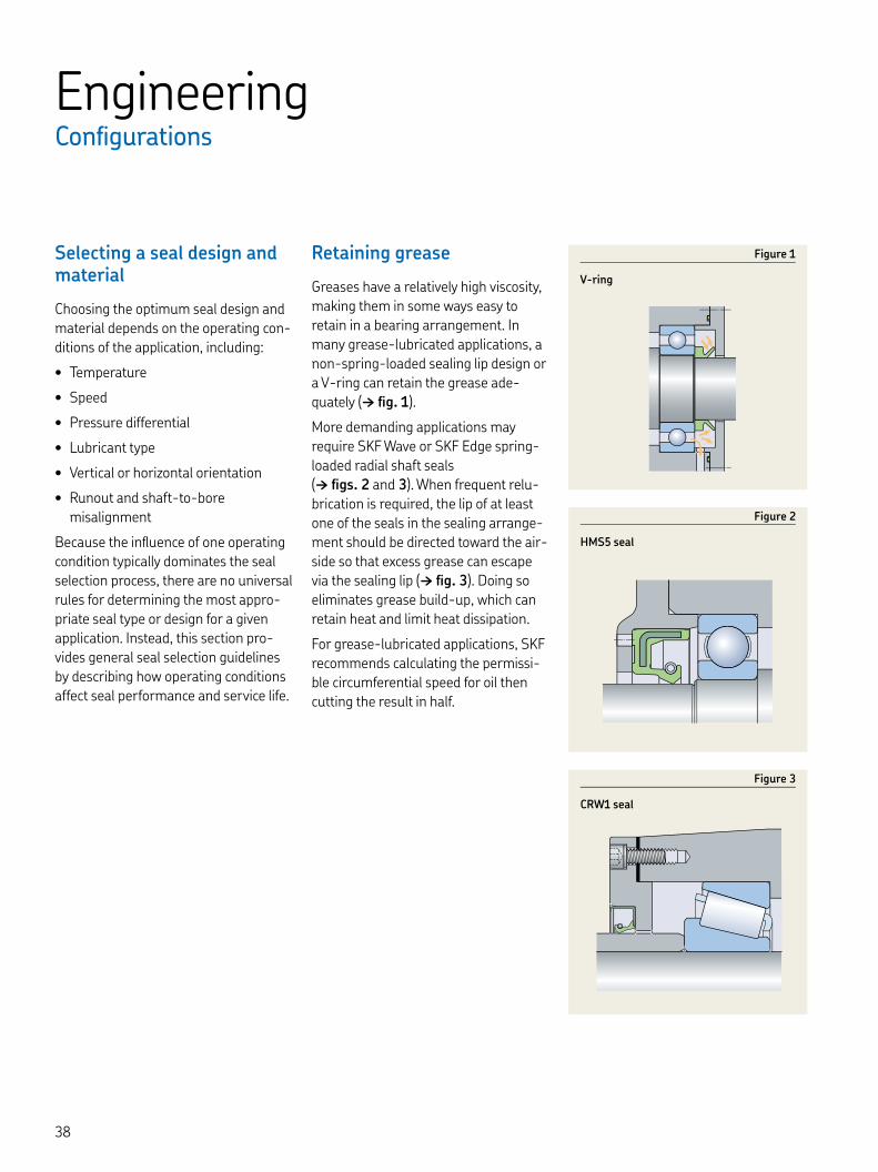
Retaining grease
Greases have a relatively high viscosity, making them in some ways easy to retain in a bearing arrangement. In many grease-lubricated applications, a non-spring-loaded sealing lip design or a V-ring can retain the grease ade-quately († fig. ).
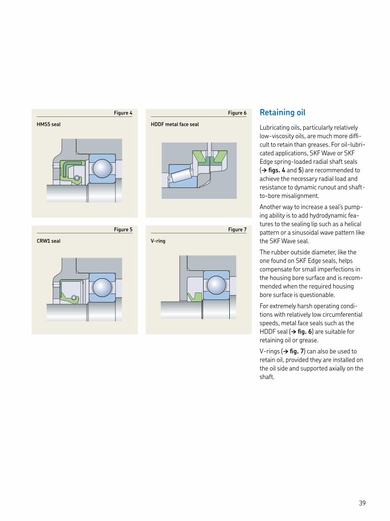
More demanding applications may require SKF Wave or SKF Edge spring-loaded radial shaft seals († figs. and ). When frequent relu-brication is required, the lip of at least one of the seals in the sealing arrange-ment should be directed toward the air-side so that excess grease can escape via the sealing lip († fig. ). Doing so eliminates grease build-up, which can retain heat and limit heat dissipation.
For grease-lubricated applications, SKF recommends calculating the permissi-ble circumferential speed for oil then cutting the result in half.
Figure
V-ring
Figure
CRW seal
Figure
HMS seal
Retaining oil
Lubricating oils, particularly relatively low-viscosity oils, are much more diffi-cult to retain than greases. For oil-lubri-cated applications, SKF Wave or SKF Edge spring-loaded radial shaft seals († figs. and ) are recommended to achieve the necessary radial load and resistance to dynamic runout and shaft-to-bore misalignment.
Another way to increase a seal’s pump-ing ability is to add hydrodynamic fea-tures to the sealing lip such as a helical pattern or a sinusoidal wave pattern like the SKF Wave seal.
The rubber outside diameter, like the one found on SKF Edge seals, helps compensate for small imperfections in the housing bore surface and is recom-mended when the required housing bore surface is questionable.
For extremely harsh operating condi-tions with relatively low circumferential speeds, metal face seals such as the HDDF seal († fig. ) are suitable for retaining oil or grease.
V-rings († fig. ) can also be used to retain oil, provided they are installed on the oil side and supported axially on the shaft.
Figure
HDDF metal face seal
Figure
HMS seal
Figure
V-ring
Figure
CRW seal

EngineeringConfigurations
Excluding contaminants
Radial shaft seals used primarily for contaminant exclusion should be installed with the lip pointing outward. When additional protection is needed, SKF recommends a seal design that incorporates an auxiliary lip, such as HMSA or CRWA seals.
For tough operating conditions, SKF Wave lip seals († fig. ) with hydrody-namic features are recommended. To further enhance sealing efficiency, two single-lip seals can be arranged in tan-dem († fig. ) or a double-lip seal (such the HDSE seal) is suitable († fig. ).
V-rings († fig. ) are used primarily to exclude contaminants. These seals act as flingers and rotate with the shaft and seal against a surface perpendicular to the shaft. V-rings and axial clamp seals are often used as secondary seals to protect the primary seals from coarse contaminants.
None of these seal arrangements are intended for oil retention.
Figure
CRW seal
Figure
CRW seals in tandem
Figure
HDSE seal
Figure
V-ring

Retaining lubricants and excluding contaminants
For many applications, excluding con-taminants is just as important as retain-ing lubricants. Seals with an auxiliary lip, such as HMSA seals († fig. ), are appropriate for such applications.
Another option is to use two seals installed in opposite directions († figs. and ) or two opposing V-rings († fig. ) with a spacing washer.
For extremely harsh operating condi-tions, SKF recommends using HDDF metal face seals († fig. on page ), provided that the sliding velocity of the mating surfaces is within the permissi-ble range.
Separating two different media
When an application has to keep two liquids from coming into contact with each other, SKF recommends using two separate seals († figs. and ) posi-tioned with their lips facing in opposite directions. For this option the sealing lips must be spring-loaded.
Figure
Two seals in opposite direction
Figure
V-ring
Figure
HMSA seal
Figure
CRW seals
Figure
Two seals in opposite direction
Figure
HMS seals
EngineeringSpecial considerations
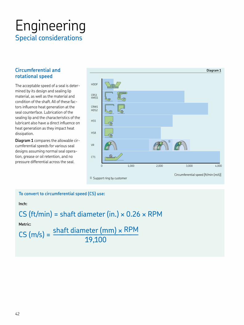
Circumferential and rotational speed
The acceptable speed of a seal is deter-mined by its design and sealing lip material, as well as the material and condition of the shaft. All of these fac-tors influence heat generation at the seal counterface. Lubrication of the sealing lip and the characteristics of the lubricant also have a direct influence on heat generation as they impact heat dissipation.
Diagram compares the allowable cir-cumferential speeds for various seal designs assuming normal seal opera-tion, grease or oil retention, and no pressure differential across the seal.
) Support ring by customer
Diagram
Circumferential speed [ft/min (m/s)]
0 5 1 5
HDDF
CRS1HMS5
CRW1
HDS2
HS5
HS8
VR
CT1
1 0 2 0
0 1,000 3,0002,000 4,000
To convert to circumferential speed (CS) use:
Inch:
CS (ft/min) = shaft diameter (in.) × . × RPMMetric:
CS (m/s) = shaft diameter (mm) × RPM––––––––––––
,
)
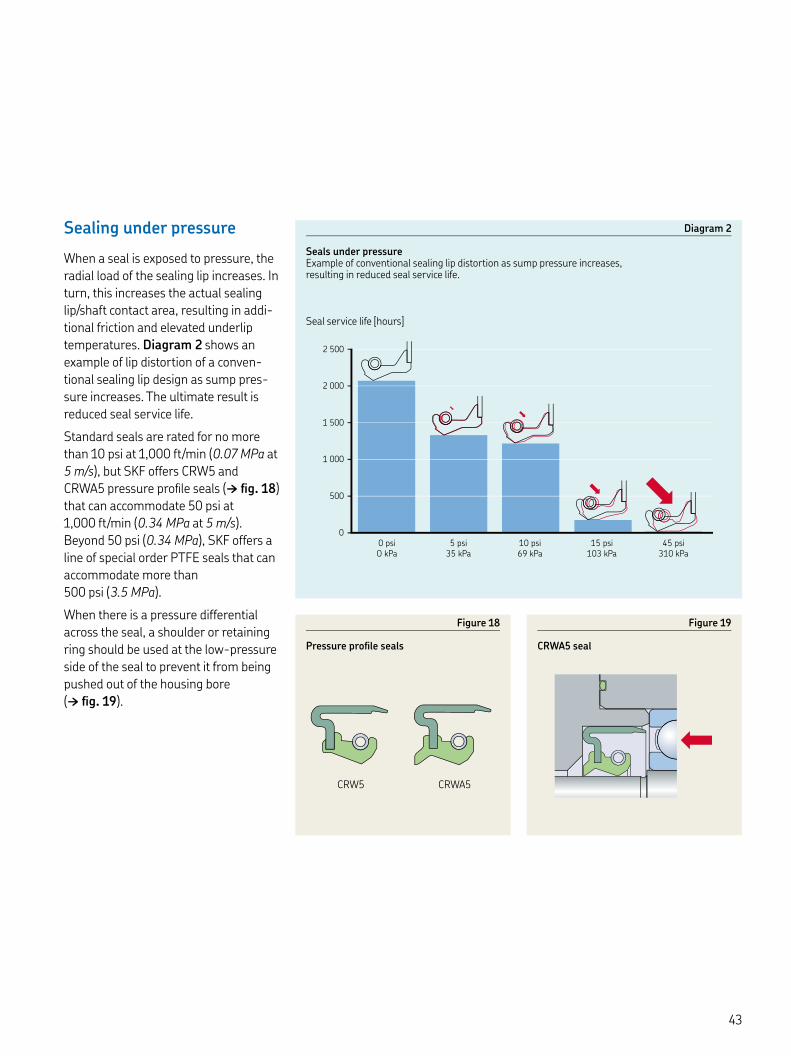
Sealing under pressure
When a seal is exposed to pressure, the radial load of the sealing lip increases. In turn, this increases the actual sealing lip/shaft contact area, resulting in addi-tional friction and elevated underlip temperatures. Diagram shows an example of lip distortion of a conven-tional sealing lip design as sump pres-sure increases. The ultimate result is reduced seal service life.
Standard seals are rated for no more than psi at , ft/min (. MPa at m/s), but SKF offers CRW and CRWA pressure profile seals († fig. ) that can accommodate psi at , ft/min (. MPa at m/s). Beyond psi (. MPa), SKF offers a line of special order PTFE seals that can accommodate more than psi (. MPa).
When there is a pressure differential across the seal, a shoulder or retaining ring should be used at the low-pressure side of the seal to prevent it from being pushed out of the housing bore († fig. ).
Diagram
Seals under pressureExample of conventional sealing lip distortion as sump pressure increases, resulting in reduced seal service life.
500
1 000
1 500
2 000
2 500
0
0 psi
O kPa
5 psi
35 kPa
10 psi
69 kPa
15 psi
103 kPa
45 psi
310 kPa
Seal service life [hours]
Figure
Pressure profile seals
Figure
CRWA seal
CRW CRWA
EngineeringSpecial considerations
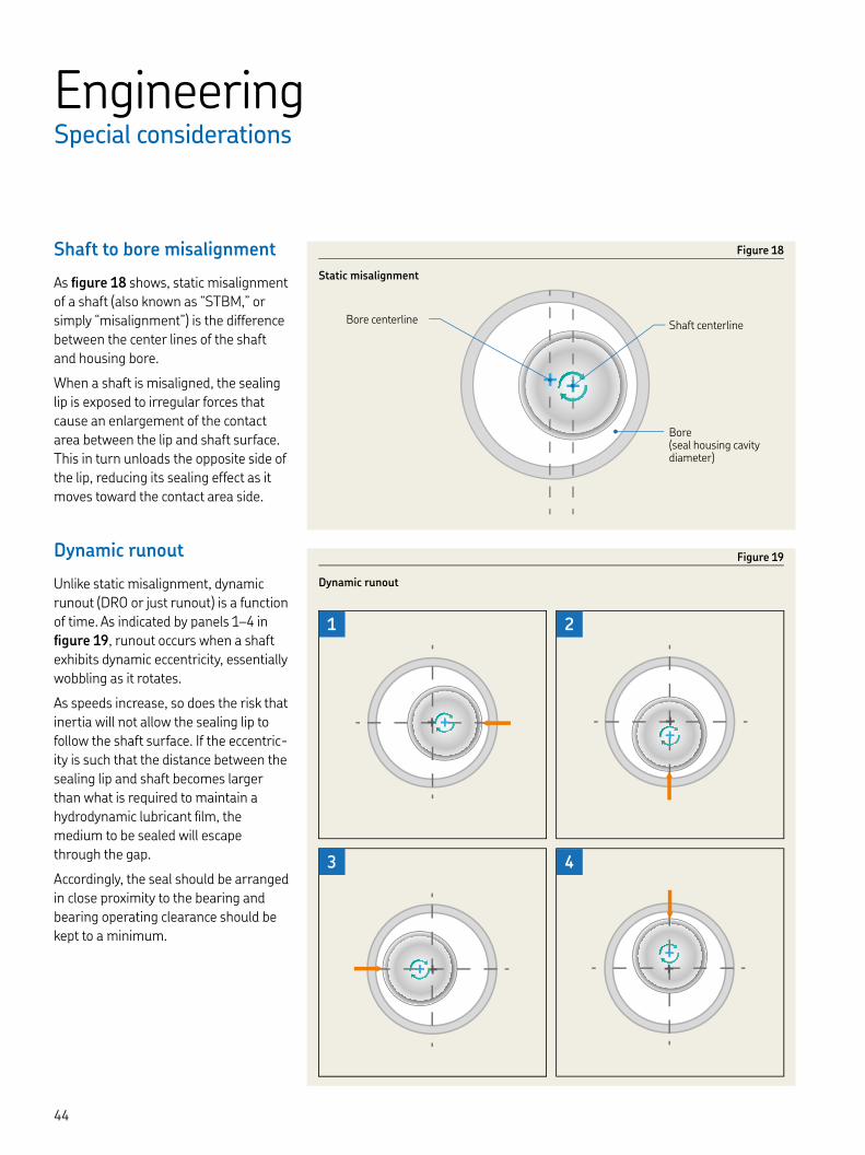
Shaft to bore misalignment
As figure shows, static misalignment of a shaft (also known as “STBM,” or simply “misalignment”) is the difference between the center lines of the shaft and housing bore.
When a shaft is misaligned, the sealing lip is exposed to irregular forces that cause an enlargement of the contact area between the lip and shaft surface. This in turn unloads the opposite side of the lip, reducing its sealing effect as it moves toward the contact area side.
Dynamic runout
Unlike static misalignment, dynamic runout (DRO or just runout) is a function of time. As indicated by panels – in figure , runout occurs when a shaft exhibits dynamic eccentricity, essentially wobbling as it rotates.
As speeds increase, so does the risk that inertia will not allow the sealing lip to follow the shaft surface. If the eccentric-ity is such that the distance between the sealing lip and shaft becomes larger than what is required to maintain a hydrodynamic lubricant film, the medium to be sealed will escape through the gap.
Accordingly, the seal should be arranged in close proximity to the bearing and bearing operating clearance should be kept to a minimum.
++ +
+
+
++++
1 2
3 4
+
++
+
++
Figure
Static misalignment
Figure
Dynamic runout
Bore centerline Shaft centerline
Bore (seal housing cavity diameter)


Hardware specifications
Tolerances
The diameter of the shaft d at the counterface should be machined to the tolerances provided in table for inch size shafts and table for metric shafts.
Out-of-roundness must be less than . in. (, mm) at a maximum of lobes or less than . in. (, mm) at a maximum of lobes.
If components with an interference fit will pass over the counterface during installation, the shaft diameter should be reduced by . in. (, mm) The seal that was originally chosen can still be used without adversely affecting seal performance.
Table
Shaft tolerances - inch
Shaft diameter Diameter tolerance (RMA S-)Nominal Deviationdover incl.
in. in.
– ±. ±. ±. ±.
Table
Shaft tolerances - metric
Shaft diameter Diameter tolerance (ISO h))
Nominal Deviationdover incl. high low
mm µm
– – –
– – –
– – –
– – –
– – –
– – –
– – –
) For shaft diameters of mm and above, refer to DIN .

Shaft surface roughness
The surface roughness values of the counterface for radial shaft seals, calcu-lated according to methods described in ISO (DIN ), should be kept within the limits specified in RMA OS-- († table ).
The lower value for Ra is a minimum value. Using a lower value will adversely affect the lubricant supply to the sealing lip. The temperature rise caused by inadequate lubrication, particularly at high circumferential speeds, can lead to hardening and cracking of the sealing lip, and eventually premature seal fail-ure. If the counterface is too rough, excessive sealing lip wear will occur and seal service life will be shortened. If the value Rpm is exceeded, the seal will leak, or excessive sealing lip wear may occur.
The seal counterface surface should be free of any damage, scratches, cracks, rust or burrs and should be properly protected until final installation.
Table
Lead-in chamfers and radii
Shaft diameter Diameter RadiiNominal diifference) Seal without auxil-
iary lipSeal with auxiliary lip
d d–d r rover incl. over incl. min min min
in. mm in. mm in. mm in. mm
– . – . , . , . . . . . , . . . . , . , .
. . . . , . . . . , . , . . . . . , .
. . . , . , . . . . , . . . . . . .
. . . . . . – – . . .
d2d1 h11
r
15–30°
ZY
Burr-free
) lf the corner is blended rather than chamfered, the blended section should not be smaller than the difference in diameters d – d.
Table
Recommended shaft surface roughness values
ISO DIN RMA
µin µm µin µm µin µm
Ra – ,–, – ,–, – ,–,Rz – ,– – – – ,–,Rpm N/A N/A N/A N/A – ,–,

Hardware specifications
Lead-in chamfers
To install radial shaft seals without damaging the sealing lip, SKF recom-mends chamfering or rounding the shaft ends or shoulders († table , page ).
If the direction of installation is Z, follow the values (d – d) provided in table . If the direction of installation is Y, the shaft end could be rounded (r) or cham-fered (d – d).
To install a seal over a shaft shoulder or end that has not been rounded or chamfered, SKF recommends using an installation sleeve.
Housing bore requirements
General
To reduce the risk of seal damage during installation, the housing bore should have a to ° lead-in chamfer. The chamfer should be free of burrs and the transition radius between the seal seat and shoulder should be in accordance with the recommendations in table († page ).
In order to facilitate seal removal, holes in the housing shoulder A can be incor-porated during the design stage.
Metal-reinforced seals
The depth of a metric housing bore B for metal-cased or metal-inserted seals should be at least . in. (, mm) larger than the nominal seal width b († fig. ). The corresponding values for an inch housing bore B are . in. (, mm).
B
D H8
15–30°
A
b
Figure
Housing bore requirements
Shaft lead
Depending on the direction of rotation, directionality on the seal counterface may cause a seal to leak. Plunge grind-ing is the preferred machining method to minimize directionality (±.°) on the seal counterface.
When plunge grinding, avoid applying whole number ratios of the grinding wheel speed to the work piece speed. Instead, run the grinding wheel until it “sparks out” completely and there are no more sparks flying from the wheel to ensure that all the lead is removed. The grinding wheel should be dressed using a cluster head dressing tool and the smallest possible lateral feed, or a pro-file dressing roll without a lateral feed. The negative influence of directionality in any particular case can only be deter-mined by test running under conditions of alternating rotation.
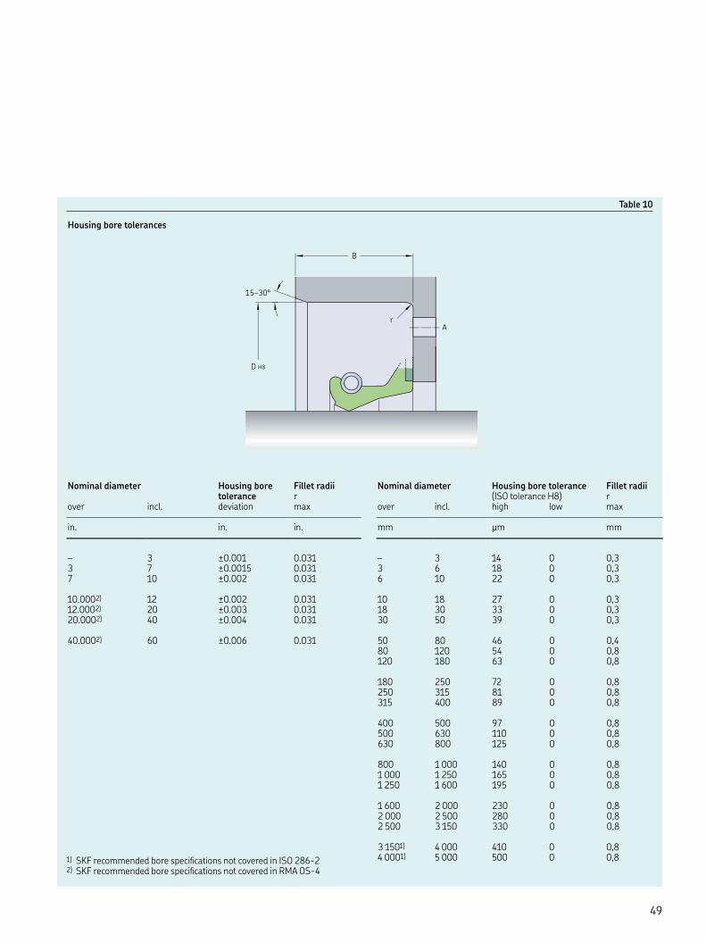
Nominal diameter Housing bore tolerance Fillet radii(ISO tolerance H) r
over incl. high low max
mm µm mm
– , , ,
, , ,
, , ,
, , ,
, , ,
, , ,
, , ,
) , ) ,
Table
Housing bore tolerances
Nominal diameter Housing bore tolerance
Fillet radiir
over incl. deviation max
in. in. in.
– ±. . ±. . ±. .
.) ±. ..) ±. ..) ±. .
.) ±. .
) SKF recommended bore specifications not covered in ISO -) SKF recommended bore specifications not covered in RMA OS-
B
D H8
15–30°
r
A
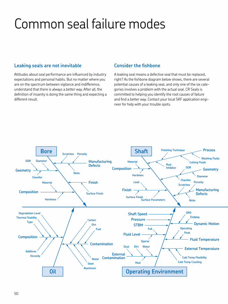
Common seal failure modes
Leaking seals are not inevitable
Attitudes about seal performance are influenced by industry expectations and personal habits. But no matter where you are on the spectrum between vigilance and indifference, understand that there is always a better way. After all, the definition of insanity is doing the same thing and expecting a different result.
Consider the fishbone
A leaking seal means a defective seal that must be replaced, right? As the fishbone diagram below shows, there are several potential causes of a leaking seal, and only one of the six cate-gories involves a problem with the actual seal. CR Seals is committed to helping you identify the root causes of failure and find a better way. Contact your local SKF application engi-neer for help with your trouble spots.
Geometry
Composition
Composition
Shaft Speed
Pressure
STBM Dynamic Motion
Fluid Temperature
External Temperature
Fluid Level
ExternalContamination
Contamination
Finish
ManufacturingDefects
Composition
Finish
Scratches
Scratches
Porosity
Finishing Technique
Porosity
Diameter
WaterDust Dirt
Material
Full
Diameter
ODR
Material
Hardness
Nicks
Nicks
ChamferChamfer
Hardness
Sparse
Mud
Surface Finish
Carbon
DRO
Endplay
Operating
Peak
Degradation Level
Thermal Stability
Type
Aluminum
Steel
Water
Fuel
Dirt
Cold Temp Cracking
Cold Temp Flexibility
Lead
Surface ParametersSurface Finish
Geometry
Process
ManufacturingDefects
OOR
Cutting Fluids
Washing Fluids
RustInhibitor
Viscosity
Additives
Bore Shaft
Oil Operating Environment
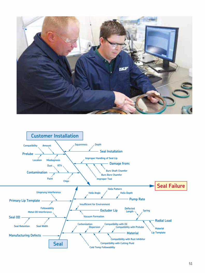
Pump Rate
Radial Load
DeflectedLengthMetal OD Interference
AmountCompatibility
LocationImproper Handling of Seal Lip
Squareness Depth
Misdiagnosis
Lip Template
Material
Improper Tool
Burs Bore Chamfer
Burs Shaft Chamfer
Cold Temp Followability
Compatibility with Cutting Fluid
Compatibility with Rust Inhibitor
Seal Retention Seal Width
ChipsPaint
Followability
Vacuum Formation
Contamination
Prelube
Unsprung Interference
Primary Lip Template
Seal OD
Manufacturing Defects
Dust RTV
Seal Installation
Damage from:
Helix Pattern
Spring
Helix Depth
CarbonizationDispersion
Compatibility with OilCompatibility with Prelube
Helix Angle
Insufficient for Environment
Excluder Lip
Material
Customer Installation
Seal
Seal Failure

Common seal failure modes
Excessive wear
Possible root causes
• Elevated internal operating pressure
• External contaminant ingress
• Excessive radial load or interference
• Lack of adequate lubrication
• Internal contaminant ingress
• Incorrect material selected for the application
• Seal reached normal end of life
• Shaft running surface too rough
Potential solutions
• Remove contamination
• Switch to high wear seal material or increase lubrication at lip interface
• Follow RMA / ISO standards for surface finish
• Reduce radial load
Nicks, scratches, or cuts in lip contact area
Possible root causes
• Installation tool or bullet with sharp edge
• Seal installed over defects in shaft
• Seal installed over shaft through hole, keyway, or splines
• Inconsistent manufacturing trimming operation
• Damage caused during packaging or handling
Potential solutions
• Protect lip by covering splines, keyways and holes with chamfered sleeve or tape
• Keep screwdrivers and other sharp tools away from seal lip
• Regularly inspect seal lips before installation
Extra wide wear patch on seal lip
Cut in seal lip causes gap in shaft contact
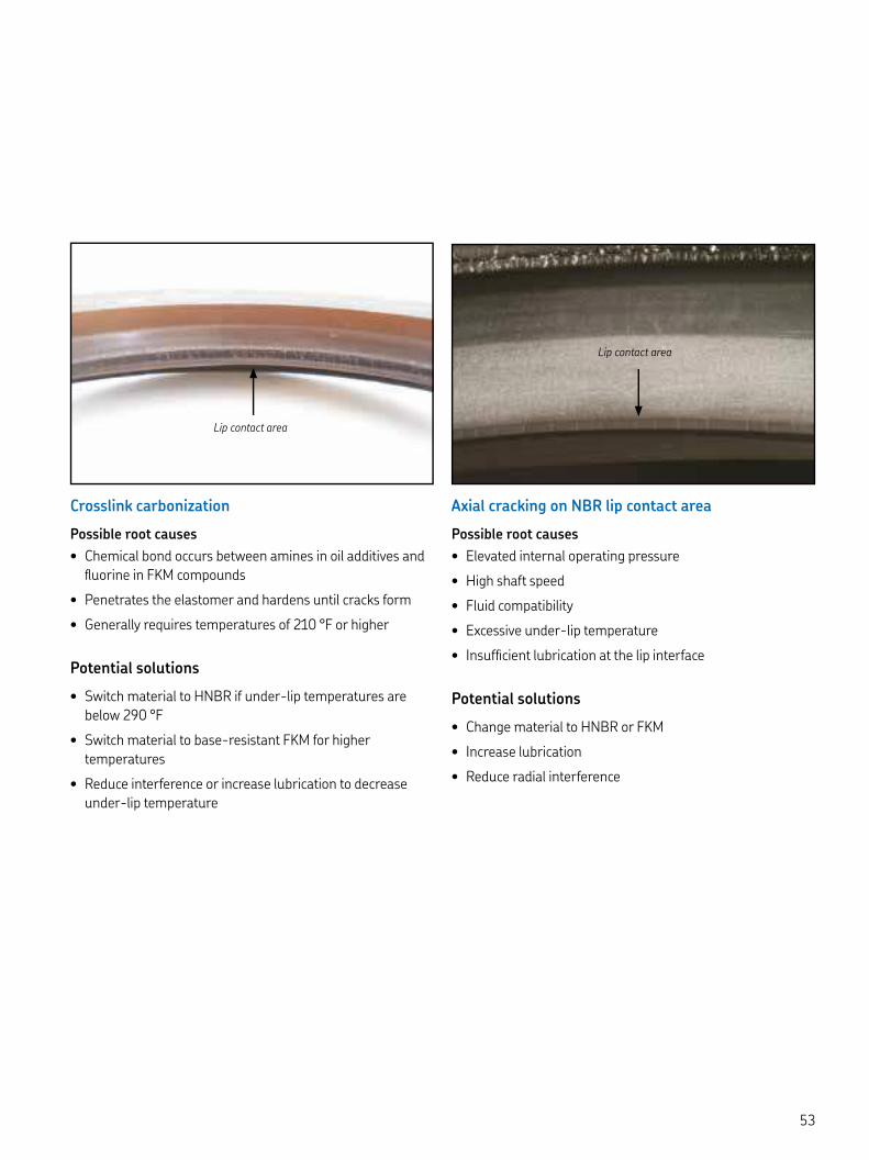
Crosslink carbonization
Possible root causes
• Chemical bond occurs between amines in oil additives and fluorine in FKM compounds
• Penetrates the elastomer and hardens until cracks form
• Generally requires temperatures of °F or higher
Potential solutions
• Switch material to HNBR if under-lip temperatures are below °F
• Switch material to base-resistant FKM for higher temperatures
• Reduce interference or increase lubrication to decrease under-lip temperature
Axial cracking on NBR lip contact area
Possible root causes
• Elevated internal operating pressure
• High shaft speed
• Fluid compatibility
• Excessive under-lip temperature
• Insufficient lubrication at the lip interface
Potential solutions
• Change material to HNBR or FKM
• Increase lubrication
• Reduce radial interference
Lip contact area
Lip contact area

Common seal failure modes
Inverted seal lip
Possible root causes
• Poor assembly procedures
• High internal operating pressure
Potential solutions
• Switch to HDS springless design, HDS garter spring design with Springcover, or HSS
• Modify installation tool and/or procedure
• If failure is pressure-induced, use pressure seal
Seal damaged during installation
Possible root causes
• Improper or worn installation tool
• Direct contact with hammer on seal
• Inadequate lead in chamfer on the bore
• Undersized bore
Potential solutions
• Add proper bore chamfer per recommendations and check bore diameter
• Use installation tool designed for the specific installation procedure
• Reevaluate installation procedure
Rubber seal OD sheared off by sharp leading edge of bore
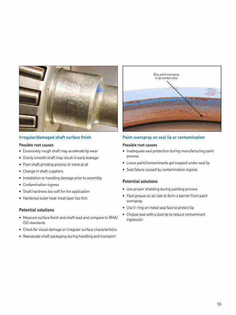
Irregular/damaged shaft surface finish
Possible root causes
• Excessively rough shaft may accelerate lip wear
• Overly smooth shaft may result in early leakage
• Poor shaft grinding process or none at all
• Change in shaft suppliers
• Installation or handling damage prior to assembly
• Contamination ingress
• Shaft hardness too soft for the application
• Hardened outer heat-treat layer too thin
Potential solutions
• Measure surface finish and shaft lead and compare to RMA/ISO standards
• Check for visual damage or irregular surface characteristics
• Reevaluate shaft packaging during handling and transport
Paint overspray on seal lip or contamination
Possible root causes
• Inadequate seal protection during manufacturing paint process
• Loose paint/contaminants get trapped under seal lip
• Seal failure caused by contamination ingress
Potential solutions
• Use proper shielding during painting process
• Pack grease on air side to form a barrier from paint overspray
• Use V-ring on metal seal face to protect lip
• Choose seal with a dust lip to reduce contaminant ingression
Blue paint overspray in lip contact area

Can Install Solid Seal Around
End of Shaft?
Oper. Temp. < °F & Shaft Speed
< ft/min?
Blind Installation?
Multiple potential solutions. Contact
Application Engineering with the Seals Request
(SR) form. HDS w/o Spring Cover
HDS w/ Spring Cover
HS or more rigid reinforced HSS
HS or more rigid reinforced HSS
HS or more rigid HSS
HS or more rigid HSS
HDS
Contact Application Engineering with the
Seals Request (SR) form.
CRWA w/ Dust Lipor CRW w/o Dust LipNBR (R) for < °FFKM (V) for < °F
HM, HM,HM or HM
Depending on Size
Below /" (< mm)
Either Inch or Metric
to PSI . – . bar
to PSI . bar
Above /" (> mm)
Yes. Cover plate holds seals in place. Yes.
Solid seal.
No. Split seal.
Excessive contamination issues?
Grease retention and/or contamination exclusion
No cover plate
Grease
Oil
Oil
Metric
No Yes
No
NoYes
Yes
Yes
No
No
No
Yes
No
Yes
Yes
Blind Installation?
Seal Retained by Cover Plate?
Lubrication
Lubrication
Find a stocked catalog
solution?
Internal Pressure?
Metric or InchShaft & Bore
Need Dust Exclusion?
Blind Installation?
Need Heavy Duty / Extreme Bore
Retention?
Oper. Temp. < °F & Shaft Speed
< ft/min?
HMSA w/ Dust Lipor HMS w/o Dust LipNBR (RG) for < °FFKM (V) for < °F
CRWHA w/ Dust Lipor CRWH w/o Dust Lip
NBR (R) for < °FFKM (V) for < °F
CRWA w/ Dust Lipor CRW w/o Dust LipNBR (R) for < °FFKM (V) for < °F
Depending upon application
expectations, you may find a stocked
catalog seal up to " or mm.
Otherwise, continue with heavy industrial
seals (SKF Flex).
STOP
No. Continue with SKF Flex
seal.
Size not available in
HM, HM,HM or HM
Can’t find the right size or solution? Contact Application Engineering with the Seals Request (SR) form.
START HERE
ST
OC
KE
D C
ATA
LOG
SE
ALS
CU
ST
OM
HE
AV
Y IN
DU
ST
RIA
L S
EA
LS (S
KF
Flex
)
SR Form = Seal Request Form NBR = Buna N Nitrile XNBR = Carboxylated NBR HNBR = Hydrogenated NBR FKM = Fluoro Rubber
Continuous operating temperature:
NBR - to ˚F (- to ˚C)XNBR - to ˚F (- to ˚C)HNBR - to ˚F (- to ˚C)FKM - to ˚F (- to ˚C)
KEY
/” Shaft Diameter
Decision Tree for CR Seals

Start here to find the seal you need
To optimize seal and equipment
performance, proper seal selec-
tion is essential. Choosing the
right seal for the job is a step-by-
step process of elimination that
defines seal compatibility based
on key operating requirements.
With this all-new edition of the
CR Seals handbook, SKF is mak-
ing the seal selection process as
easy as possible.
To find the seal for your applica-
tion, go to the red “START HERE”
triangle in the decision tree at left
and take it step-by-step.
Find out even more online
An interactive version of this deci-sion tree with the added functional-ity of the four links below is available online.
Just scan the QR code to launch the app:
– Seal request form
– Information pop-up
– Link to catalog page
– Heavy Industrial (HIS) part numbering
Table
SKF Flex seals size capability chart
Shaft diameter Bore diameter Bore depthDifference between
shaft and bore
From To From To From To From To
inch . . . . . – . –
HS / HSS / HSSG
mm . . . . . – . –
inch . . . . . . . .mm . . . . . . . .
inch . . . . . . . .mm . . . . . . . .
inch . . . . . . . .mm . . . . . . . .
inch . . . . . . . .
HDS , / HDSF ,mm . . . . . . . .
inch . . . . . . . .mm . . . . . . . .
inch . . . . . . . .
\ ,mm . . . . . . . .
inch . . . . . . . .mm . . . . . . . .
inch . . . . . . . .
HDSmm . . . . . . . .
inch . . . . . . . .mm . . . . . . . .
inch . . . . . . . .
HDSHmm . . . . . . . .
inch . . . . . . . .mm . . . . . . . .
inch . . . . . . . .
HDSA / HDSA mm . . . . . . . .
inch . . . . . . . .mm . . . . . . . .

Seal capability matrixes
Seals for general industrial applications, selected main designs
RG, R Nitrile rubber (NBR)
V Fluorocarbon rubber (FKM)
H Hydrogenated nitrile rubber (HNBR)
P Polyacrylate elastomer (ACM)
Seal designs Design
Outside diameter Sealing lip Auxiliary lip
Configuration Material code
technology A = Contacting B = Non-contacting
–
Rubber RG, V SKF Edge B (HMSA)
HMS HMSA
Metal R, V, P SKF Wave N/A
CRW CRWH
Metal R, V, P SKF Wave B
CRWA CRWHA
Metal R, V SKF Wave A (CRWA)
CRW CRWA
Metal R, V, P Std Oil N/A
CRS CRSH
Metal R, V, P Std Oil A
CRSA CRSHA
Metal R, V Grease N/A
HM HM HM HM
Metal R Grease N/A
TL TL TL TL
Rubber R Grease N/A
X X X X
Metal R OD running lip A
SCOT
Rubber H SKF Wave A
PLUS XL

Matrix 1
Maximum* shaft-to-bore misalignment (STBM)
Maximum* dynamic runout (DRO) TIR
Maximum* pressure differential Maximum* shaft surface speed
in. mm in. mm psi MPa ft/min m/s
0.015 0.38 0.020 0.51 7 0.05 2,755 14
0.025 0.64 0.025 0.64 10 0.07 3,600 18
0.025 0.64 0.025 0.64 10 0.07 3,600 18
0.005 0.13 0.005 0.13 50 0.35 2,000 10
0.015 0.38 0.020 0.51 10 0.07 3,600 18
0.015 0.38 0.020 0.51 10 0.07 3,600 18
0.005 0.13 0.003 0.08 3 0.07 2,000 10
0.015 0.38 0.010 0.25 3 0.02 500 2.54
0.015 0.38 0.010 0.25 3 0.02 500 2.54
0.005 0.13 0.005 0.13 2 0.014 2,000 10
0.005 0.13 0.005 0.13 2 0.014 2,000 10
* Stated maximum parameters apply only when all other parameters are at normal operating conditions.
59

SKF Flex seals for heavy industrial applications, selected main designs
Standard design(preferred design)
Other basic designs Material code
Maximum* pressure differential
Maximum* shaft-to-bore misalignment
Maximum* dynamic runout
Maximum* shaft surface speed
(STBM) (DRO) TIR
– psi (MPa) in. (mm) in. (mm) ft/min (m/s)
R . . ,
D (.) (.) ()
H
HDS HDSL HDSF HDSH V
R . . ,
D (.) (.) (.) ()
H
HDS HDS HDSF HDSL V
HDSL HDSF HDSH
R . . ,
D (.) (.) (.) ()
H
HDSA HDSA V
R . . HS: , ()
D (.) (.) (.) HS: , ()
H
HS HS V
R . . HS: , ()
D (.) (.) HS: , (.)
H HS: , ()
HS HS HS V
R . . , ()depending on the operating conditions
V (.) (.) (.)
HSS HSS HSS
HSS HSS
R . . , ()depending on the operating conditions
V (.) (.)
HSSG HSSG HSSG
HSSG HSSG
Seal capability matrixes
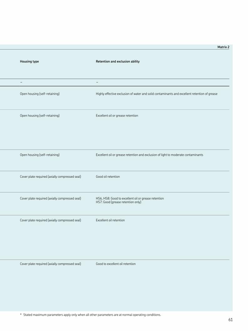
Matrix
Housing type Retention and exclusion ability
– –
Open housing (self-retaining) Highly effective exclusion of water and solid contaminants and excellent retention of grease
Open housing (self-retaining) Excellent oil or grease retention
Open housing (self-retaining) Excellent oil or grease retention and exclusion of light to moderate contaminants
Cover plate required (axially compressed seal) Good oil retention
Cover plate required (axially compressed seal) HS, HS: Good to excellent oil or grease retention HS: Good (grease retention only)
Cover plate required (axially compressed seal) Excellent oil retention
Cover plate required (axially compressed seal) Good to excellent oil retention
* Stated maximum parameters apply only when all other parameters are at normal operating conditions.

Profile overview
Rotary shaft seals - oil applications
Wear sleeves
Rotary shaft seals - grease applications
■ SKF Edge
■ SKF Wave
■ HMS
HM
CRSA
HMSAP
■ CRWA
SKF Speedi-Sleeve LDSLV
■ HMSA
HM
HM
CRSH
SCOT
■ CRWH
HM
HMA
TL X
CRSHA
■ CRW
■ CRWHA
HM
■ C
HMS
■ CRW
■ HDW
HD
HM
CRS
HMSA
■ CRWA
■ PLUS XL
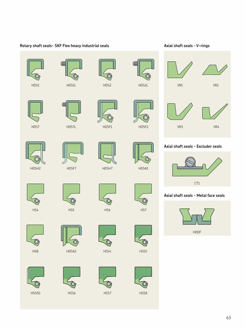
Rotary shaft seals- SKF Flex heavy industrial seals Axial shaft seals - V-rings
Axial shaft seals - Excluder seals
Axial shaft seals - Metal face seals
HDS
HS
HSS
HDSF
CT
HDDF
HSS
HDSL
HS
HDSH
HDS
HSS
HS
HDS
HDSL
HSSHS
HDSF
HDSH
HSSG
HDSF
HDSA
HDSL
HDSA
VR
VR
VR
VR
HSS
HS

SKF Flex seal designation system Inch size Decimal code
Key Inch Key Inch
.
. .
. .
. .
. .
. .
. .
. .
. .
. .
. .
. .
. .
. .
. .
. .
. .
. .
. .
. .
. .
. .
. .
. .
. .
. .
. .
. .
. .
. .
. .
. .
.
Rubber seals HS/HSS – Axial cover plate required
All-rubber: HS HS HS HS HS HS
Reinforced all-rubber HSS HSS HSS HSS HSS HSS
Lubrication groove for HSS HSSG HSSG HSSG HSSG
Auxiliary lip (dust lip) HSA HSA
Radial clamp HSAC HSAC
Solid ✓ ✓
Split ✓ ✓ ✓
SKF springcover ✓ ✓ ✓
Threaded spring connection ✓ ✓ ✓ ✓
Hook-and-eye connection (Above in or mm)
✓ ✓
Control-wire connection
✓
Dimension / Designation examples
Shaft (d)
Decimal Code
Bore (D)
Decimal Code
Bore Depth (B)
Decimal Code
." 1200 ." 1316 ." 48." 616 ." 700 ." 32." 1816 ." 2016 ." 64
mm – .mm – mm –
Inch sizes are stated in /th of an inch, as shown in the table on the left. “L” indicates a mm lug length from the table on the right.
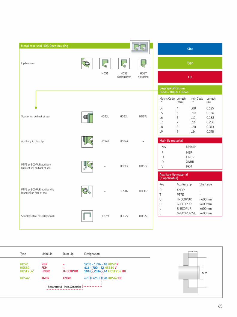
Metal case seal HDS Open housing
Lip features
HDS HDS Springcover
HDS no spring
Spacer lug on back of seal HDSL HDSL HDSL
Auxiliary lip (dust lip) HDSA HDSA –
PTFE or ECOPUR auxiliary lip (dust lip) on back of seal
– HDSF HDSF
PTFE or ECOPUR auxiliary lip (dust lip) on face of seal
– HDSH HDSH
Stainless steel case (Optional) HDS HDS HDS
Size
Type
Lip
Lugs specifications HDSL / HDSL / HDSL
Metric Code L*
Length (mm)
Inch Code L*
Length (in)
L L .
L L .
L L .
L L .
L L .
L L .
Main lip material
Key Main lip
R NBR
H HNBR
D XNBR
V FKM
Auxiliary lip material (if applicable)
Key Auxiliary lip Shaft size
D XNBR –
T PTFE –
U H-ECOPUR <mm
U G-ECOPUR >mm
L S-ECOPUR <mm
L G-ECOPUR SL >mm
Type
Main Lip
Dust Lip
Designation
HDS NBR – - - HDS RHSSG FKM – - - HSSG V HDSFL HNBR H-ECOPUR - - HDSFL HU
HDSA XNBR XNBR X . X HDSA DD
Separators (- inch, X metric)

CR Seals product listings
Understanding key table elements
Designed to be user-friendly, CR Seals and product listings convey a good deal of information on every line. As you familiarize yourself with the tables, keep these need-to-know basics in mind:
Seal and product sizes
All size listings for all CR Seals products are arranged by ascending shaft diame-ters, segregated as inch sizes (green bars) and metric sizes (blue bars). All bore and width sizes listed under the green bars are in inches, while all sizes listed under blue bars are in mm.
Bore / width
Once you have selected the right shaft size, you will need to identify the seals with a matching bore size. The recom-mended tolerance ranges for shaft and bore can be found on pages -. While it is important to choose a seal with a close match to shaft and bore, it is less important to choose a seal with a predetermined width. As long as the seal is short enough not to protrude out of the bore, it will work just fine.
Preferred designs
Highlighted in bold in the “Part Number” and “Seal Type” columns, preferred seal design listings represent the highest performing or otherwise best suited sealing solution for a given shaft diameter.
Lip material
R = NBR (nitrile rubber)
RG = NBR with advanced oil resistance and pumping ability
D = XNBR (carboxylated nitrile)
H = HNBR (hydrogenated nitrile)
V = FKM (fluorocarbon rubber)
P = ACM (polyacrylate elastomer)
T = PTFE (polytetrafluoroethylene)
Seal technologies
W = SKF Wave: Featuring the patented SKF Wave lip design, these are the most robust standard seals ever made.
E = SKF Edge: SKF Edge shaft seals HMS and HMSA combine an SKF-developed NBR compound with a rubber outside diameter according to ISO/DIN global design standards – pri-marily available in metric sizes.
F = SKF Flex: SKF Flex seals deliver heavy-duty performance in fully cus-tomizable sizes and features to fit and perform in the application.
S = Standard oil seal: SKF carries some older designs that do not have the modern advancements of the SKF Edge or SKF Wave lips, but may be adequate for some applications. Use these when SKF Edge or SKF Wave seals are not available in the size needed.
G = Grease seal: Oil seals can handle oil or grease applications, but grease seals do not have the garter spring needed for oil retention, so they are for grease only. Normally you point the lip away from grease if the main concern is water/dirt ingression, which also allows the grease to purge if needed.
Key features
▲ WasteWatcher: Indicates that the product is most likely to be in stock at our distributors and our own SKF warehouses. The CR Seals Waste-Watcher program helps distributors optimize seal inventories.
■ Bore-Tite: Indicates the seal uses SKF Bore-Tite, a green, water-based acrylic sealant used as a coating on the outside diameter of the seal.
◤ SS Case: Indicates the seal has a stainless steel seal case.
◎ SS Spring: Indicates the seal has a stainless steel seal lip spring.
◆ Pressure seal up to psi: Suitable for higher-pressure sealing applica-tions; typical industrial shaft seals can handle only up to or psi.
◇ Cover plate required: Proper seal installation and operation requires a cover plate, which clamps down axi-ally on an all-rubber seal to hold it in place in many large diameter seal applications.
Contents
Rotary shaft seals .........................
V-rings ........................................
LDSLV wear sleeves .................
Metal face seals ..........................
Axial clamp seals .......................
Pressure seals .............................
Grease lubricated seals ..............
SKF Speedi-Sleeve ...................

Rotary shaft seals Size listing
Key features: ▲ WasteWatcher ■ Bore-Tite ◤ SS Case ◎ SS Spring ◆ Pressure seal up to 50 psi ◇ Cover plate required
HousingBore Width
Part Number Seal Type
Lip Mat'l
Seal Tech
Fea-tures
INCH Shaft Diameter – 0.188" (4.78 mm)
. . HM R G
METRIC Shaft Diameter – 5 mm (0.197")
XX HMS R HMS R S
METRIC Shaft Diameter – 6 mm (0.236")
XX HM R HM R G XX HMS RG HMS RG E XX HMS V HMS V E ◎
XX HMSA RG HMSA RG E XX HMSA V HMSA V E ◎
XX HMS RG HMS RG E XX HMS V HMS V E ◎
▲ XX HMSA RG HMSA RG E XX HMSA V HMSA V E ◎
XX HMS RG HMS RG E XX HMS V HMS V E ◎
▲ XX HMSA RG HMSA RG E XX HMSA V HMSA V E ◎
INCH Shaft Diameter – 0.250" (6.35 mm)
. . HM R G. . HM R G ■
. . HM R G. . HM R G. . ▲ CRW R W ■◤◎
. . CRW V W
METRIC Shaft Diameter – 7 mm (0.276”)
XX HMS RG HMS RG E XX HMS V HMS V E ◎
XX HMSA RG HMSA RG E XX HMSA V HMSA V E ◎
XX HMS R HMS R S XX HMSA R HMSA R S XX HMS RG HMS RG E XX HMS V HMS V E ◎
▲ XX HMSA RG HMSA RG E XX HMSA V HMSA V E ◎
INCH Shaft Diameter – 0.313" (7.95 mm)
. . HM R G. . HM R G ■
. . HM R G ■
. . HM R G. . CRWA R W ◆
. . CRWA V W ◆
. . CRWA V W ◆
. . HM R G. . CRWA R W ◆
. . HM R G. . HM R G. . CRWA R W ◆
METRIC Shaft Diameter – 8 mm (0.315")
XX HM R HM R G XX HMS R HMS R S XX HMS RG HMS RG E XX HMS V HMS V E ◎
▲ XX HMSA RG HMSA RG E XX HMSA V HMSA V E ◎
XX HMS RG HMS RG E XX HMS V HMS V E ◎
XX HMSA RG HMSA RG E XX HMSA V HMSA V E ◎
XX HMS RG HMS RG E XX HMS V HMS V E ◎
▲ XX HMSA RG HMSA RG E
Housing Bore
Width
Part Number
Seal Type
Lip Mat'l
Seal Tech
Fea-tures
METRIC Shaft Diameter (cont.) – 0.315" (8 mm)
XX HMSA V HMSA V E ◎
XX HMS RG HMS RG E XX HMS V HMS V E ◎
XX HMSA RG HMSA RG E XX HMSA V HMSA V E ◎
METRIC Shaft Diameter – 9 mm (0.354")
XX HM R HM R G XX HMSA R HMSA R S XX HMS RG HMS RG E XX HMS V HMS V E ◎
XX HMSA RG HMSA RG E XX HMSA V HMSA V E ◎
XX HMS R HMS R S ■
XX HMS R HMS R S
INCH Shaft Diameter – 0.375" (9.53 mm)
. . HM R G. . HM R G ◤
. . HM R G. . HM R G ■
. . ▲ CRW R W. . CRW V W ■
. . CRW R W ◤◎◆
. . HM R G. . ▲ CRWA R W ■
. . CRW P W ■
. . ▲ CRW R W ■
. . HM R G. . ▲ CRW R W. . CRW R W. . CRW V W ■
. . ▲ CRW R W. . CRW V W ■◆
METRIC Shaft Diameter – 10 mm (0.394")
XX HM R HM R G XX HMS RG HMS RG E XX HMS V HMS V E ◎
▲ XX HMSA RG HMSA RG E XX HMSA V HMSA V E ◎
XX HMS RG HMS RG E XX HMS V HMS V E ◎
▲ XX HMSA RG HMSA RG E XX HMSA V HMSA V E ◎
XX HMS RG HMS RG E XX HMS V HMS V E ◎
XX HMSA RG HMSA RG E XX HMSA V HMSA V E ◎
XX HMS RG HMS RG E XX HMS V HMS V E ◎
▲ XX HMSA RG HMSA RG E XX HMSA V HMSA V E ◎
XX HMS RG HMS RG E XX HMS V HMS V E ◎
▲ XX HMSA RG HMSA RG E XX HMSA V HMSA V E ◎
XX HMS RG HMS RG E XX HMS V HMS V E ◎
▲ XX HMSA RG HMSA RG E XX HMSA V HMSA V E ◎
XX HMS RG HMS RG E XX HMS V HMS V E ◎
▲ XX HMSA RG HMSA RG E XX HMSA V HMSA V E ◎
XX HMS R HMS R S ■
XX HMS RG HMS RG E XX HMS V HMS V E ◎
▲ XX HMSA RG HMSA RG E

Seal tech: W = SKF Wave E = SKF Edge F = SKF Flex S = standard oil G = grease Bold part numbers are preferred designs
Rotary shaft seals Size listing
Housing Bore
Width
Part Number
Seal Type
Lip Mat'l
Seal Tech
Fea-tures
METRIC Shaft Diameter (cont.) – 10 mm (0.394")
XX HMSA V HMSA V E ◎
XX HMS R HMS R S XX HMS R HMS R S XX HMSA R HMSA R S
INCH Shaft Diameter – 0.404" (10.26 mm)
. . HM R G. . HM R G
METRIC Shaft Diameter – 11 mm (0.433")
XX HMS R HMS R S XX HMSA V HMSA V S XX HMS R HMS R S XX HMS R HMS R S XX HMS R HMS R S
)INCH Shaft Diameter – 0.438" (11.13 mm
. . HM R G. . CRW P W ■
. . ▲ CRW R W. . CRWA R W. . CRW V W ■
. . HM R G. . ▲ CRW R W ■
. . ▲ CRW R W ■
. . HM P G. . HM R G
METRIC Shaft Diameter – 12 mm (0.472")
. SSLEEVEShaft Ø.-.mm - 'on-shaft' width mm - flange Ø.mm
XX HM R HM R G XX HM R HM R G XX HMS R HMS R S XX HMSA R HMSA R S XX HM R HM R G XX HMS RG HMS RG E XX HMS V HMS V E ◎
▲ XX HMSA RG HMSA RG E XX HMSA V HMSA V E ◎
XX CRSA R CRSA R S XX HMS R HMS R S XX HM R HM R G XX HMS RG HMS RG E XX HMS V HMS V E ◎
▲ XX HMSA RG HMSA RG E XX HMSA V HMSA V E ◎
XX HMS RG HMS RG E XX HMS V HMS V E ◎
XX HMSA RG HMSA RG E XX HMSA V HMSA V E ◎
XX HMSAP R HMSAP R S ◆
XX CRW R CRW R W ■
XX CRW V CRW V W ■
XX HMS RG HMS RG E XX HMS V HMS V E ◎
XX HMSA RG HMSA RG E XX HMSA V HMSA V E ◎
XX HMSAP R HMSAP R S ◆
XX HMS RG HMS RG E XX HMS V HMS V E ◎
▲ XX HMSA RG HMSA RG E XX HMSA V HMSA V E ◎
. XX. HMS R HMS R S XX CRW R CRW R W XX HMS RG HMS RG E XX HMS V HMS V E ◎
▲ XX HMSA RG HMSA RG E XX HMSA V HMSA V E ◎
Housing Bore
Width
Part Number
Seal Type
Lip Mat'l
Seal Tech
Fea-tures
METRIC Shaft Diameter (cont.) – 12 mm (0.472")
XX CRW R CRW R W XX HMS R HMS R S XX CRW P CRW P W ■
XX CRW R CRW R W ■
XX HMS RG HMS RG E XX HMS V HMS V E ◎
▲ XX HMSA RG HMSA RG E XX HMSA V HMSA V E ◎
XX HMS RG HMS RG E XX HMS V HMS V E ◎
▲ XX HMSA RG HMSA RG E XX HMSA V HMSA V E ◎
XX CRW R CRW R W XX CRW V CRW V W ■
XX HMS RG HMS RG E XX HMS V HMS V E ◎
▲ XX HMSA RG HMSA RG E XX HMSA V HMSA V E ◎
XX CRW R CRW R W ■
XX HMS RG HMS RG E XX HMS V HMS V E ◎
XX HMSA RG HMSA RG E XX HMSA V HMSA V E ◎
INCH Shaft Diameter – 0.500" (12.70 mm)
. SSLEEVEShaft Ø.-." - 'on-shaft' width ." - flange Ø."
. . HM R G. . HM R G ■
. . HM R G ■
. . HM R G ■
. . HM R G. . CRW D W ■
. . ▲ CRW R W ■
. . CRW V W ■
. . CRWA V W ■
. . CRWA V W ■◤◎
. . HM R G. . CRWA R W ■
. . CRWA R W ■◆
. . CRWA V W ■◆
. . CRW R W ■
. . HM R G ■
. . CRW R W ■
. . CRW V W ■◎
. . CRWA P W ■
. . ▲ CRWA R W ■
. . CRWA V W ■◎◆
. . HM R G ■
. . CRWA R W ■◆
. . CRW R W. . CRW V W ■
. . CRWA R W ■
. . CRWA V W ■
. . CRWA R W ■◆
. . CRWA V W ■◆
. . HM R G ■
. . ▲ CRW R W ■
. . CRW P W ■
. . ▲ CRW R W ■
. . CRW V W ■
. . ▲ CRW R W ■
. . CRW V W ■
METRIC Shaft Diameter – 13 mm (0.512" )
XX HMS RG HMS RG E XX HMS V HMS V E ◎
▲ XX HMSA RG HMSA RG E XX HMSA V HMSA V E ◎

Rotary shaft seals Size listing
Key features: ▲ WasteWatcher ■ Bore-Tite ◤ SS Case ◎ SS Spring ◆ Pressure seal up to 50 psi ◇ Cover plate required
HousingBore Width
Part Number Seal Type
Lip Mat'l
Seal Tech
Fea-tures
METRIC Shaft Diameter (cont.) – 13 mm (0.512" )
XX CRS R CRS R S XX HMS R HMS R S XX HMSA R HMSA R S XX HMS R HMS R S
INCH Shaft Diameter – 0.531" (13.49 mm)
. . CRWA S W ■
INCH Shaft Diameter – 0.546" (13.87 mm)
. . CRW P W. . CRSA R S
METRIC Shaft Diameter – 14 mm (0.551")
. SSLEEVEShaft Ø.-mm - 'on-shaft' width .mm - flange Ø.mm
XX HM R HM R G XX HM R HM R G XX HMS R HMS R S XX HMSA R HMSA R S XX HMSA R HMSA R S XX HMS RG HMS RG E XX HMS V HMS V E ◎
▲ XX HMSA RG HMSA RG E XX HMSA V HMSA V E ◎
XX HMS RG HMS RG E XX HMS V HMS V E ◎
XX HMSA RG HMSA RG E XX HMSA V HMSA V E ◎
XX HMSA P HMSA P S XX CRW V CRW V W ■
XX HMS R HMS R S XX HMS RG HMS RG E XX HMS V HMS V E ◎
▲ XX HMSA RG HMSA RG E XX HMSA V HMSA V E ◎
. . HM R G ■
XX HMS RG HMS RG E XX HMS V HMS V E ◎
▲ XX HMSA RG HMSA RG E XX HMSA V HMSA V E ◎
XX CRW R CRW R W XX HMS R HMS R S
INCH Shaft Diameter – 0.554" (14.07 mm)
. . ▲ CRW R W ■◤◎
INCH Shaft Diameter – 0.563" (14.30 mm)
. SSLEEVEShaft Ø.-." - 'on-shaft' width ." - flange Ø."
. . HM R G. . CRW D W ■
. . HM R G ■
. . HM R G ■
. . CRW R W ■◤◎
. . CRW V W ■
. . CRWA R W ■
. . ▲ CRW R W ■
. . ▲ CRW R W ■
. . CRW V W ■
. . CRWA R W ■
. . HM R G. . ▲ CRW R W ■
. . ▲ CRW R W ■
METRIC Shaft Diameter – 15 mm (0.591")
SSLEEVEShaft Ø.-.mm - 'on-shaft' width mm - flange Ø.mm
XX HM R HM R G
Housing Bore
Width
Part Number
Seal Type
Lip Mat'l
Seal Tech
Fea-tures
METRIC Shaft Diameter (cont.) – 15 mm (0.591")
XX HM V HM V G HMSA P S XX HM R HM R G XX HMS R HMS R S XX HMSA R HMSA R S XX HMS RG HMS RG E XX HMS V HMS V E ◎
▲ XX HMSA RG HMSA RG E XX HMSA V HMSA V E ◎
XX HMS RG HMS RG E XX HMS V HMS V E ◎
▲ XX HMSA RG HMSA RG E XX HMSA V HMSA V E ◎
XX HMS RG HMS RG E XX HMS V HMS V E ◎
XX HMSA RG HMSA RG E XX HMSA V HMSA V E ◎
XX CRW P CRW P W ■
XX HMS R HMS R S XX HMS RG HMS RG E XX HMS V HMS V E ◎
▲ XX HMSA RG HMSA RG E XX HMSA V HMSA V E ◎
XX CRW R CRW R W ■
XX HMS R HMS R S. . HM R G ■
. . CRW R W ■
XX HMS RG HMS RG E XX HMS V HMS V E ◎
▲ XX HMSA RG HMSA RG E XX HMSA V HMSA V E ◎
XX CRW R CRW R W XX CRW V CRW V W ■
XX HMS RG HMS RG E XX HMS V HMS V E ◎
▲ XX HMSA RG HMSA RG E XX HMSA V HMSA V E ◎
XX HMSAP R HMSAP R S ◆
XX HMSAP R HMSAP R S ◆
XX CRW P CRW P W ■
XX CRW R CRW R W ■
XX HMS RG HMS RG E XX HMS V HMS V E ◎
▲ XX HMSA RG HMSA RG E XX HMSA V HMSA V E ◎
XX HMS R HMS R S XX HMS RG HMS RG E XX HMS V HMS V E ◎
XX HMSA RG HMSA RG E XX HMSA V HMSA V E ◎
XX HMS RG HMS RG E XX HMS V HMS V E ◎
▲ XX HMSA RG HMSA RG E XX HMSA V HMSA V E ◎
INCH Shaft Diameter – 0.594" (15.09 mm)
. . CRSA R S. . CRSA R S ■
INCH Shaft Diameter – 0.624" (15.85 mm)
. . HM R G ■
INCH Shaft Diameter – 0.625" (15.88 mm)
. SSLEEVEShaft Ø.-.” - ‘on-shaft’ width .” - flange Ø.”
. GSLEEVEShaft Ø.-.” - ‘on-shaft’ width .” - flange Ø.”
. . HM R G. . HM V G

Seal tech: W = SKF Wave E = SKF Edge F = SKF Flex S = standard oil G = grease Bold part numbers are preferred designs
Rotary shaft seals Size listing
HousingBore Width
Part Number Seal Type
Lip Mat'l
Seal Tech
Fea-tures
INCH Shaft Diameter (cont.) – 0.625" (15.88 mm)
. . HM R G ■
. . HM V G ■
. . HM R G ■
. . ▲ CRW R W ■◎
. . ▲ CRW R W ■
. . CRWA R W ■
. . CRWA V W ■◎
. . CRWA R W ■◆
. . HM P G ■
. . ▲ CRW R W ■
. . HM R G ■
. . CRW R W ■
. . CRW V W ■
. . CRW R W ■◆
. . ▲ CRWA R W ■
. . CRWA V W ■
. . HM R G ■
. . CRWA V W ■◆
. . CRWA R W ■◆
. . HM R G. . HM R G. . CRW R W ■◆
. . ▲ CRWA R W ■
. . CRWA V W ■
. . CRW R W ■
. . CRW V W ■
. . ▲ CRWA R W ■
. . HM R G ■
. . CRWA R W ◤◎◆
. . CRWA V W ◤◎◆
. . HM R G ■
. . CRW R W ■
. . CRW V W ■
. . CRW P W ■◆
. . ▲ CRWA R W ■
. . CRWA V W ■
. . HM R G ■
. . CRWA R W ■◤ ◎◆
. . ▲ CRWHA R W ■
. . ▲ CRW R W ■
. . CRW V W ■◎◆
. . CRWA V W
METRIC Shaft Diameter – 16 mm (0.630")
. SSLEEVEShaft Ø.-mm - 'on-shaft' width .mm - flange Ø.mm
HMA R G XX HM R HM R G XX HM R HM R G XX HMS R HMS R S XX HMSA R HMSA R S XX HMS RG HMS RG E XX HMS V HMS V E ◎
▲ XX HMSA RG HMSA RG E XX HMSA V HMSA V E ◎
. HMSA P S XX HMS P HMS P S XX HMS R HMS R S XX CRW R CRW R W ■
XX HMS RG HMS RG E XX HMS V HMS V E ◎
▲ XX HMSA RG HMSA RG E XX HMSA V HMSA V E ◎
XX CRW R CRW R W ■
XX HMS RG HMS RG E XX HMS V HMS V E ◎
▲ XX HMSA RG HMSA RG E XX HMSA V HMSA V E ◎
XX CRW R CRW R W
Housing Bore
Width
Part Number
Seal Type
Lip Mat'l
Seal Tech
Fea-tures
METRIC Shaft Diameter (cont.) – 16 mm (0.630")
XX HMS RG HMS RG E XX HMS V HMS V E ◎
▲ XX HMSA RG HMSA RG E XX HMSA V HMSA V E ◎
XX CRW R CRW R W XX HMS RG HMS RG E XX HMS V HMS V E ◎
▲ XX HMSA RG HMSA RG E XX HMSA V HMSA V E ◎
XX HMSA R HMSA R S XX CRW R CRW R W XX CRWA R CRWA R W ■
XX HMS RG HMS RG E XX HMS V HMS V E ◎
XX HMSA RG HMSA RG E XX HMSA V HMSA V E ◎
INCH Shaft Diameter – 0.656" (16.66 mm)
. . ▲ CRW R W ■
. . ▲ CRW R W ■
. . ▲ CRW R W ■
. . ▲ CRW R W ■
METRIC Shaft Diameter – 17 mm (0.669")
SSLEEVE XX HM R HM R G XX HMS R HMS R S XX HMSA R HMSA R S. . CRW R W ■
. CRW R W ■◤◎
. CRW R W ■
XX HMSA R HMSA R S XX HMSA R HMSA R S XX CRW R CRW R W ◎
XX CRW V CRW V W ■
XX HMS RG HMS RG E XX HMS V HMS V E ◎
▲ XX HMSA RG HMSA RG E XX HMSA V HMSA V E ◎
XX HMS RG HMS RG E XX HMS V HMS V E ◎
XX HMSA RG HMSA RG E XX HMSA V HMSA V E ◎
XX HMS R HMS R S XX CRW R CRW R W ■
XX HMS RG HMS RG E XX HMS V HMS V E ◎
▲ XX HMSA RG HMSA RG E XX HMSA V HMSA V E ◎
. . HM R G ■
XX CRW R CRW R W ■
XX HMS RG HMS RG E XX HMS V HMS V E ◎
▲ XX HMSA RG HMSA RG E XX HMSA V HMSA V E ◎
XX HMS R HMS R S XX CRW R CRW R W ■
XX CRW V CRW V W ■
XX HMS RG HMS RG E XX HMS V HMS V E ◎
▲ XX HMSA RG HMSA RG E XX HMSA V HMSA V E ◎
XX HMS RG HMS RG E XX HMS V HMS V E ◎
▲ XX HMSA RG HMSA RG E XX HMSA V HMSA V E ◎
. . CRW V W ◤◎
XX CRW R CRW R W XX HMS RG HMS RG E
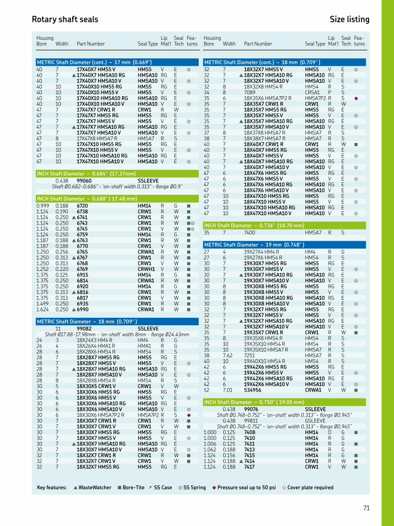
Rotary shaft seals Size listing
Key features: ▲ WasteWatcher ■ Bore-Tite ◤ SS Case ◎ SS Spring ◆ Pressure seal up to 50 psi ◇ Cover plate required
HousingBore Width
Part Number Seal Type
Lip Mat'l
Seal Tech
Fea-tures
METRIC Shaft Diameter (cont.) – 17 mm (0.669")
XX HMS V HMS V E ◎
▲ XX HMSA RG HMSA RG E XX HMSA V HMSA V E ◎
XX HMS RG HMS RG E XX HMS V HMS V E ◎
XX HMSA RG HMSA RG E XX HMSA V HMSA V E ◎
XX CRW R CRW R W XX HMS RG HMS RG E XX HMS V HMS V E ◎
▲ XX HMSA RG HMSA RG E XX HMSA V HMSA V E ◎
XX HMSA R HMSA R S XX HMS RG HMS RG E XX HMS V HMS V E ◎
XX HMSA RG HMSA RG E XX HMSA V HMSA V E ◎
INCH Shaft Diameter – 0.684" (17.37mm)
. SSLEEVEShaft Ø.-." - 'on-shaft' width ." - flange Ø."
INCH Shaft Diameter – 0.688" ( 17.48 mm)
. . HM R G ■
. . CRW R W ■
. . ▲ CRW R W ■
. . CRW R W ■◎
. . CRW V W ■◎
. . HM R G ■
. . ▲ CRW R W ■
. . CRW V W ■
. . CRWA R W ■
. . ▲ CRW R W ■
. . CRW V W ■
. . CRWH V W ■
. . HM R G ■
. . CRWA R W ■
. . HM R G ■
. . ▲ CRW R W ■
. . CRW V W ■
. . CRW R W ■
. . ▲ CRWA R W ■
METRIC Shaft Diameter – 18 mm (0.709" )
SSLEEVEShaft Ø.-.mm - 'on-shaft' width mm - flange Ø.mm
XX HM R HM R G XX HMA R HMA R G XX HMS R HMS R S XX HMS RG HMS RG E XX HMS V HMS V E ◎
▲ XX HMSA RG HMSA RG E XX HMSA V HMSA V E ◎
XX HMS R HMS R S XX CRW V CRW V W XX HMS RG HMS RG E XX HMS V HMS V E ◎
XX HMSA RG HMSA RG E XX HMSA V HMSA V E ◎
XX HMSAP R HMSAP R S ◆
XX CRW R CRW R W ■
XX CRW V CRW V W ■
XX HMS RG HMS RG E XX HMS V HMS V E ◎
▲ XX HMSA RG HMSA RG E XX HMSA V HMSA V E ◎
XX CRW R CRW R W ■
XX CRW V CRW V W ■
XX HMS RG HMS RG E
Housing Bore
Width
Part Number
Seal Type
Lip Mat'l
Seal Tech
Fea-tures
METRIC Shaft Diameter (cont.) – 18 mm (0.709" )
XX HMS V HMS V E ◎
▲ XX HMSA RG HMSA RG E XX HMSA V HMSA V E ◎
XX HMS R HMS R S CRSA P S XX HMSAP R HMSAP R S ◆
XX CRW R CRW R W XX HMS RG HMS RG E XX HMS V HMS V E ◎
▲ XX HMSA RG HMSA RG E XX HMSA V HMSA V E ◎
XX HMSA R HMSA R S XX HMSA R HMSA R S XX CRW R CRW R W ■
XX HMS RG HMS RG E XX HMS V HMS V E ◎
▲ XX HMSA RG HMSA RG E XX HMSA V HMSA V E ◎
XX HMS RG HMS RG E XX HMS V HMS V E ◎
XX HMSA RG HMSA RG E XX HMSA V HMSA V E ◎
XX HMS RG HMS RG E XX HMS V HMS V E ◎
XX HMSA RG HMSA RG E XX HMSA V HMSA V E ◎
INCH Shaft Diameter – 0.736" (18.70 mm)
HMSA R S
METRIC Shaft Diameter – 19 mm (0.748" )
XX HM R HM R G XX HMS R HMS R S XX HMS RG HMS RG E XX HMS V HMS V E ◎
▲ XX HMSA RG HMSA RG E XX HMSA V HMSA V E ◎
XX HMS RG HMS RG E XX HMS V HMS V E ◎
XX HMSA RG HMSA RG E XX HMSA V HMSA V E ◎
XX HMS RG HMS RG E XX HMS V HMS V E ◎
▲ XX HMSA RG HMSA RG E XX HMSA V HMSA V E ◎
XX CRW R CRW R W ■
XX HMS R HMS R S XX HMS R HMS R S XX HMSA R HMSA R S . HMSA R S XX HMS R HMS R S XX HMS RG HMS RG E XX HMS V HMS V E ◎
XX HMSA RG HMSA RG E XX HMSA V HMSA V E ◎
. CRWA V W ■
INCH Shaft Diameter – 0.750" ( 19.05 mm)
. SSLEEVEShaft Ø.-.” - ‘on-shaft’ width .” - flange Ø.”
. GSLEEVEShaft Ø.-.” - ‘on-shaft’ width .” - flange Ø.”
. . HM D G ■
. . HM R G. . HM R G ■
. . HM R G. . HM R G ■
. . ▲ CRW R W ■
. . CRW V W ■

Seal tech: W = SKF Wave E = SKF Edge F = SKF Flex S = standard oil G = grease Bold part numbers are preferred designs
Rotary shaft seals Size listing
Housing Bore
Width
Part Number
Seal Type
Lip Mat'l
Seal Tech
Fea-tures
INCH Shaft Diameter (cont.) – 0.750" (19.05 mm)
. . HM R G. . CRW V W ◎
. . HM D G. . HM R G ◤
. . ▲ CRW R W ■
. . CRW R WOD IS GROUND
. . CRW R W ■◎
W/BRASS CASE & SS SPRING. . CRW R W ■
. . CRW V W ■
. . CRWA V W ■◤◎
. . CRWA R W ■◆
. . HM R G ■
. . ▲ CRWA R W ■
. . CRWA V W ■
. . CRWA R W ■◆
. . ▲ CRW R W ■
. . HM R G ■
. . ▲ CRW R W ■
. . HM R G ■
. . ▲ CRW R W ■
. . CRWA R W ■
. . CRW R W ■
. . CRW V W ■
. . CRWA P W ■
. . ▲ CRWA R W ■
. . CRWA V W ■
. . CRWA V W ■◆
. . HM P G. . HM R G. . HM R G ■
. . ▲ CRW R W. . CRW V W ■
. . ▲ CRWA R W ■
. . HM R G ■
. . ▲ CRW R W ■
. . CRW R W ■
. . CRW V W ■◎
. . ▲ CRWA R W ■
. . CRWA V W ■◎
. . ▲ CRW R W ■
. . CRWA V W ■
. . CRW R W ■
. . ▲ CRW R W ■
. . ▲ CRW R W ■
INCH Shaft Diameter – 0.760" (19.30 mm)
. SSLEEVEShaft Ø.-." - 'on-shaft' width ." - flange Ø."
INCH Shaft Diameter – 0.781" 19.84 mm
. SSLEEVEShaft Ø.-.” - ‘on-shaft’ width .” - flange Ø.”
. . HM R G ■
. . ▲ CRW R W. . CRW V W ■
. . ▲ CRW R W ■
. . ▲ CRW R W ■
. . CRSHA R S. . CRW P W ■
METRIC Shaft Diameter – 20 mm (0.787")
SSLEEVEShaft Ø.-.mm - ‘on-shaft’ width mm - flange Ø.mm
. SSLEEVEShaft Ø.-.mm - ‘on-shaft’ width .mm - flange Ø.mm
XX HM R HM R G XX HMS R HMS R S
Housing Bore
Width
Part Number
Seal Type
Lip Mat'l
Seal Tech
Fea-tures
METRIC Shaft Diameter (cont.) – 20 mm (0.787")
XX HMSA R HMSA R S XX HM R HM R G XX HMS R HMS R S. . CRW R W ■
XX HMS RG HMS RG E XX HMS V HMS V E ◎
XX HMSA RG HMSA RG E XX HMSA V HMSA V E ◎
XX CRS R CRS R S XX CRW R CRW R W ■
XX HMS RG HMS RG E XX HMS V HMS V E ◎
▲ XX HMSA RG HMSA RG E XX HMSA V HMSA V E ◎
XX CRS V CRS V S XX CRW R CRW R W ■
XX HMS RG HMS RG E XX HMS V HMS V E ◎
XX HMSA RG HMSA RG E XX HMSA V HMSA V E ◎
XX HMS R HMS R S XX CRW R CRW R W ■
XX HMS RG HMS RG E XX HMS V HMS V E ◎
▲ XX HMSA RG HMSA RG E XX HMSA V HMSA V E ◎
XX CRS V CRS V S XX HMS R HMS R S XX HMS RG HMS RG E XX HMS V HMS V E ◎
XX HMSA RG HMSA RG E XX HMSA V HMSA V E ◎
XX HMSA P HMSA P S XX HMS RG HMS RG E XX HMS V HMS V E ◎
XX HMSA RG HMSA RG E XX HMSA V HMSA V E ◎
XX CRW R CRW R W ■
XX CRW V CRW V W ■
XX HMS RG HMS RG E XX HMS V HMS V E ◎
▲ XX HMSA RG HMSA RG E XX HMSA V HMSA V E ◎
XX HMS RG HMS RG E XX HMS V HMS V E ◎
XX HMSA RG HMSA RG E XX HMSA V HMSA V E ◎
XX HMS RG HMS RG E XX HMS V HMS V E ◎
XX HMSA RG HMSA RG E XX HMSA V HMSA V E ◎
XX CRW R CRW R W ■
XX CRW V CRW V W ■
XX HMS RG HMS RG E XX HMS V HMS V E ◎
▲ XX HMSA RG HMSA RG E XX HMSA V HMSA V E ◎
. . CRW V W ■
XX CRW R CRW R W XX CRW V CRW V W ■
XX HMS RG HMS RG E XX HMS V HMS V E ◎
▲ XX HMSA RG HMSA RG E XX HMSA V HMSA V E ◎
XX CRW R CRW R W XX HMS RG HMS RG E XX HMS V HMS V E ◎
▲ XX HMSA RG HMSA RG E XX HMSA V HMSA V E ◎
XX HMS R HMS R S ■
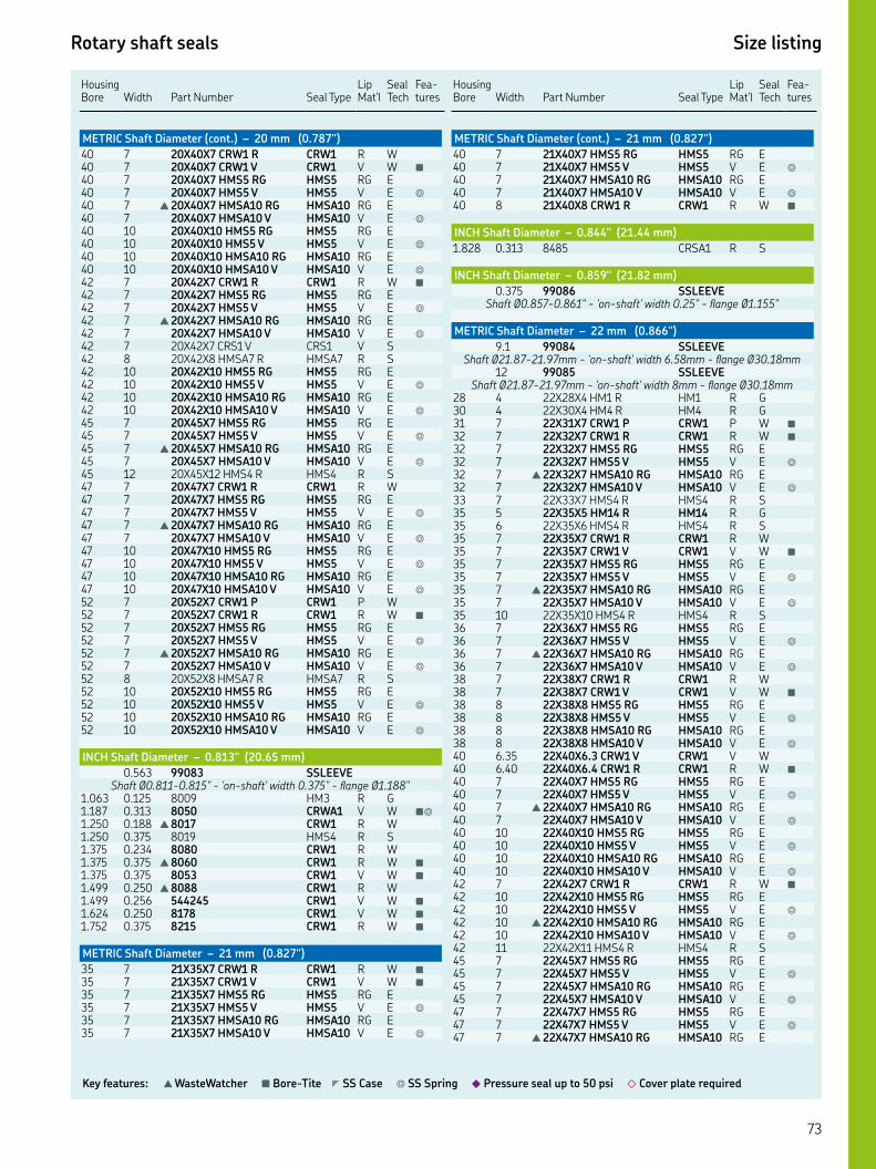
Rotary shaft seals Size listing
Key features: ▲ WasteWatcher ■ Bore-Tite ◤ SS Case ◎ SS Spring ◆ Pressure seal up to 50 psi ◇ Cover plate required
HousingBore Width
Part Number Seal Type
Lip Mat'l
Seal Tech
Fea-tures
METRIC Shaft Diameter (cont.) – 20 mm (0.787")
XX CRW R CRW R W XX CRW V CRW V W ■
XX HMS RG HMS RG E XX HMS V HMS V E ◎
▲ XX HMSA RG HMSA RG E XX HMSA V HMSA V E ◎
XX HMS RG HMS RG E XX HMS V HMS V E ◎
XX HMSA RG HMSA RG E XX HMSA V HMSA V E ◎
XX CRW R CRW R W ■
XX HMS RG HMS RG E XX HMS V HMS V E ◎
▲ XX HMSA RG HMSA RG E XX HMSA V HMSA V E ◎
XX CRS V CRS V S XX HMSA R HMSA R S XX HMS RG HMS RG E XX HMS V HMS V E ◎
XX HMSA RG HMSA RG E XX HMSA V HMSA V E ◎
XX HMS RG HMS RG E XX HMS V HMS V E ◎
▲ XX HMSA RG HMSA RG E XX HMSA V HMSA V E ◎
XX HMS R HMS R S XX CRW R CRW R W XX HMS RG HMS RG E XX HMS V HMS V E ◎
▲ XX HMSA RG HMSA RG E XX HMSA V HMSA V E ◎
XX HMS RG HMS RG E XX HMS V HMS V E ◎
XX HMSA RG HMSA RG E XX HMSA V HMSA V E ◎
XX CRW P CRW P W XX CRW R CRW R W ■
XX HMS RG HMS RG E XX HMS V HMS V E ◎
▲ XX HMSA RG HMSA RG E XX HMSA V HMSA V E ◎
XX HMSA R HMSA R S XX HMS RG HMS RG E XX HMS V HMS V E ◎
XX HMSA RG HMSA RG E XX HMSA V HMSA V E ◎
INCH Shaft Diameter – 0.813" (20.65 mm)
. SSLEEVEShaft Ø.-." - 'on-shaft' width ." - flange Ø."
. . HM R G. . CRWA V W ■◎
. . ▲ CRW R W. . HMS R S. . CRW R W. . ▲ CRW R W ■
. . CRW V W ■
. . ▲ CRW R W. . CRW V W ■
. . CRW V W ■
. . CRW R W ■
METRIC Shaft Diameter – 21 mm (0.827")
XX CRW R CRW R W ■
XX CRW V CRW V W ■
XX HMS RG HMS RG E XX HMS V HMS V E ◎
XX HMSA RG HMSA RG E XX HMSA V HMSA V E ◎
Housing Bore
Width
Part Number
Seal Type
Lip Mat'l
Seal Tech
Fea-tures
METRIC Shaft Diameter (cont.) – 21 mm (0.827")
XX HMS RG HMS RG E XX HMS V HMS V E ◎
XX HMSA RG HMSA RG E XX HMSA V HMSA V E ◎
XX CRW R CRW R W ■
INCH Shaft Diameter – 0.844" (21.44 mm)
. . CRSA R S
INCH Shaft Diameter – 0.859" (21.82 mm)
. SSLEEVEShaft Ø.-." - 'on-shaft' width ." - flange Ø."
METRIC Shaft Diameter – 22 mm (0.866")
. SSLEEVEShaft Ø.-.mm - 'on-shaft' width .mm - flange Ø.mm
SSLEEVEShaft Ø.-.mm - 'on-shaft' width mm - flange Ø.mm
XX HM R HM R G XX HM R HM R G XX CRW P CRW P W ■
XX CRW R CRW R W ■
XX HMS RG HMS RG E XX HMS V HMS V E ◎
▲ XX HMSA RG HMSA RG E XX HMSA V HMSA V E ◎
XX HMS R HMS R S XX HM R HM R G XX HMS R HMS R S XX CRW R CRW R W XX CRW V CRW V W ■
XX HMS RG HMS RG E XX HMS V HMS V E ◎
▲ XX HMSA RG HMSA RG E XX HMSA V HMSA V E ◎
XX HMS R HMS R S XX HMS RG HMS RG E XX HMS V HMS V E ◎
▲ XX HMSA RG HMSA RG E XX HMSA V HMSA V E ◎
XX CRW R CRW R W XX CRW V CRW V W ■
XX HMS RG HMS RG E XX HMS V HMS V E ◎
XX HMSA RG HMSA RG E XX HMSA V HMSA V E ◎
. XX. CRW V CRW V W . XX. CRW R CRW R W ■
XX HMS RG HMS RG E XX HMS V HMS V E ◎
▲ XX HMSA RG HMSA RG E XX HMSA V HMSA V E ◎
XX HMS RG HMS RG E XX HMS V HMS V E ◎
XX HMSA RG HMSA RG E XX HMSA V HMSA V E ◎
XX CRW R CRW R W ■
XX HMS RG HMS RG E XX HMS V HMS V E ◎
▲ XX HMSA RG HMSA RG E XX HMSA V HMSA V E ◎
XX HMS R HMS R S XX HMS RG HMS RG E XX HMS V HMS V E ◎
XX HMSA RG HMSA RG E XX HMSA V HMSA V E ◎
XX HMS RG HMS RG E XX HMS V HMS V E ◎
▲ XX HMSA RG HMSA RG E

Seal tech: W = SKF Wave E = SKF Edge F = SKF Flex S = standard oil G = grease Bold part numbers are preferred designs
Rotary shaft seals Size listing
HousingBore Width
Part Number Seal Type
Lip Mat'l
Seal Tech
Fea-tures
METRIC Shaft Diameter (cont.) – 22 mm (0.866" )
XX HMSA V HMSA V E ◎
XX CRW R CRW R W ■
XX CRW R CRW R W ■
XX HMS RG HMS RG E XX HMS V HMS V E ◎
XX HMSA RG HMSA RG E XX HMSA V HMSA V E ◎
XX HMS RG HMS RG E XX HMS V HMS V E ◎
XX HMSA RG HMSA RG E XX HMSA V HMSA V E ◎
INCH Shaft Diameter – 0.875" (22.23 mm)
. SSLEEVEShaft Ø.-." - 'on-shaft' width ." - flange Ø."
. GSLEEVEShaft Ø.-." - 'on-shaft' width ." - flange Ø."
. . HM R G. . HM V G ■
. . HM R G ■
. . ▲ CRW R W ■
. . CRW V W ■
. . CRWA V W ■◆
. . HM R G. . HM R G ◤
. . HM R G ■
. . CRW V W ■
. . HM R G ■
. . HM R G ■
. . HM R G ■
. . CRWA R W ■
. . CRW V W ■
. . CRWA R W ■◆
. . CRWA V W ■◆
. . ▲ CRW R W ■
. . ▲ CRW R W ■
. . HM R G ■
. . CRWA V W ■◎◆
. . CRW R W ■
. . CRW V W ■
. . ▲ CRWA R W ■
. . CRWA V W ■◎
. . CRW R W. . ▲ CRWA R W ■
. . HM R G. . ▲ CRW R W ■
. . HM R G. . ▲ CRW R W ■
. . CRW V W ■
. . CRWA R W ■
. . CRWA V W ■
. . ▲ CRW R W ■
. . ▲ CRW R W ■
. . ▲ CRW R W ■
. . ▲ CRW R W ■
. . CRWH V W ■
METRIC Shaft Diameter – 23 mm (0.906" )
. XX. HM R HM R G . HMS R S XX HMSA P HMSA P S XX HMS R HMS R S XX HMS RG HMS RG E XX HMS V HMS V E ◎
XX HMSA RG HMSA RG E XX HMSA V HMSA V E ◎
XX HMS R HMS R S
Housing Bore
Width
Part Number
Seal Type
Lip Mat'l
Seal Tech
Fea-tures
INCH Shaft Diameter – 0.910" (23.11 mm)
. SSLEEVEShaft Ø.-." - 'on-shaft' width ." - flange Ø."
. GSLEEVEShaft Ø.-." - 'on-shaft' width ." - flange Ø."
INCH Shaft Diameter – 0.938" (23.83 mm)
. . ▲ CRWA R W ■
. . HM R G ■
. . HM R G ■
. . ▲ CRW R W ■
. . CRW V W ■
. . ▲ CRW R W ■
. . CRW V W ■
. . ▲ CRW R W ■
. . ▲ CRW R W ■
METRIC Shaft Diameter – 24 mm (0.945" )
. SSLEEVEShaft Ø.-.mm - ‘on-shaft’ width .mm - flange Ø.mm
XX HM R HM R G XX HMS RG HMS RG E XX HMS V HMS V E ◎
▲ XX HMSA RG HMSA RG E XX HMSA V HMSA V E ◎
XX CRW V CRW V W ■
XX HMS RG HMS RG E XX HMS V HMS V E ◎
▲ XX HMSA RG HMSA RG E XX HMSA V HMSA V E ◎
XX CRW V CRW V W ■
XX HMS R HMS R S XX HMS RG HMS RG E XX HMS V HMS V E ◎
▲ XX HMSA RG HMSA RG E XX HMSA V HMSA V E ◎
XX HMS RG HMS RG E XX HMS V HMS V E ◎
XX HMSA RG HMSA RG E XX HMSA V HMSA V E ◎
XX HMS RG HMS RG E XX HMS V HMS V E ◎
▲ XX HMSA RG HMSA RG E XX HMSA V HMSA V E ◎
XX CRW R CRW R W ■
XX HMS RG HMS RG E XX HMS V HMS V E ◎
XX HMSA RG HMSA RG E XX HMSA V HMSA V E ◎
XX HMSA R HMSA R S CRWA V W XX HMS RG HMS RG E XX HMS V HMS V E ◎
XX HMSA RG HMSA RG E XX HMSA V HMSA V E ◎
INCH Shaft Diameter – 0.950" (24.13 mm)
. . CRW P W ■
INCH Shaft Diameter – 0.969" (24.61 mm)
. SSLEEVEShaft Ø.-." - 'on-shaft' width ." - flange Ø."
. SSLEEVEShaft Ø.-." - 'on-shaft' width ." - flange Ø."
. . CRWA P W ■
. . ▲ CRW R W. . CRW V W ■
. . ▲ CRW R W ■
. . CRW V W ■
. . CRW R W ■

Rotary shaft seals Size listing
Key features: ▲ WasteWatcher ■ Bore-Tite ◤ SS Case ◎ SS Spring ◆ Pressure seal up to 50 psi ◇ Cover plate required
HousingBore Width
Part Number Seal Type
Lip Mat'l
Seal Tech
Fea-tures
INCH Shaft Diameter (cont.) – 0.969" (24.61 mm)
. . ▲ CRWA R W ■
. . ▲ CRW R W ■
. . CRW R W ■
. . CRS R S ■
METRIC Shaft Diameter – 25 mm (0.984" )
SSLEEVEShaft Ø.-.mm - 'on-shaft' width .mm - flange Ø.mm
GSLEEVEShaft Ø.-.mm - 'on-shaft' width .mm - flange Ø.mm
XX HM R HM R G XX HMS R HMS R S XX HMSA R HMSA R S XX CRSA R CRSA R S XX HM R HM R G XX HMS R HMS R S. . CRW V W ◤◎
XX HM R HM R G XX CRW V CRW V W ■
XX HMS RG HMS RG E XX HMS V HMS V E ◎
▲ XX HMSA RG HMSA RG E XX HMSA V HMSA V E ◎
XX CRW R CRW R W ■
XX CRW V CRW V W ■
XX HMS RG HMS RG E XX HMS V HMS V E ◎
▲ XX HMSA RG HMSA RG E XX HMSA V HMSA V E ◎
XX CRW R CRW R W ■
XX HMS RG HMS RG E XX HMS V HMS V E ◎
▲ XX HMSA RG HMSA RG E XX HMSA V HMSA V E ◎
XX HMS RG HMS RG E XX HMS V HMS V E ◎
XX HMSA RG HMSA RG E XX HMSA V HMSA V E ◎
XX HMS RG HMS RG E XX HMS V HMS V E ◎
XX HMSA RG HMSA RG E XX HMSA V HMSA V E ◎
XX CRW R CRW R W ■
XX CRW V CRW V W ■
XX HMS RG HMS RG E XX HMS V HMS V E ◎
▲ XX HMSA RG HMSA RG E XX HMSA V HMSA V E ◎
. XX. HMS R HMS R S XX CRW R CRW R W ■
XX CRW V CRW V W ■
XX HMS RG HMS RG E XX HMS V HMS V E ◎
▲ XX HMSA RG HMSA RG E XX HMSA V HMSA V E ◎
. . CRW V W ■◤◎
XX HMS RG HMS RG E XX HMS V HMS V E ◎
XX HMSA RG HMSA RG E XX HMSA V HMSA V E ◎
XX CRW R CRW R W XX CRW R CRW R W ◤◎
XX CRW V CRW V W ■
XX HMS RG HMS RG E XX HMS V HMS V E ◎
▲ XX HMSA RG HMSA RG E XX HMSA V HMSA V E ◎
XX HMS RG HMS RG E XX HMS V HMS V E ◎
XX HMSA RG HMSA RG E
Housing Bore
Width
Part Number
Seal Type
Lip Mat'l
Seal Tech
Fea-tures
METRIC Shaft Diameter (cont.) – 25 mm (0.984")
XX HMSA V HMSA V E ◎
XX HMS RG HMS RG E XX HMS V HMS V E ◎
XX HMSA RG HMSA RG E XX HMSA V HMSA V E ◎
. . CRWA R W ■◆
XX HMS RG HMS RG E XX HMS V HMS V E ◎
▲ XX HMSA RG HMSA RG E XX HMSA V HMSA V E ◎
XX HMS RG HMS RG E XX HMS V HMS V E ◎
XX HMSA RG HMSA RG E XX HMSA V HMSA V E ◎
XX CRW R CRW R W XX CRW V CRW V W ■
XX HMS RG HMS RG E XX HMS V HMS V E ◎
▲ XX HMSA RG HMSA RG E XX HMSA V HMSA V E ◎
. . CRWA V W ◤◎
. . CRWA V W ■◤ ◎◆
XX CRW R CRW R W ■
XX HMS RG HMS RG E XX HMS V HMS V E ◎
▲ XX HMSA RG HMSA RG E XX HMSA V HMSA V E ◎
XX HMS RG HMS RG E XX HMS V HMS V E ◎
XX HMSA RG HMSA RG E XX HMSA V HMSA V E ◎
XX HMS RG HMS RG E XX HMS V HMS V E ◎
XX HMSA RG HMSA RG E XX HMSA V HMSA V E ◎
XX HMSA R HMSA R S XX HMS RG HMS RG E XX HMS V HMS V E ◎
▲ XX HMSA RG HMSA RG E XX HMSA V HMSA V E ◎
XX CRWA V CRWA V W ◎
XX HMSAP R HMSAP R S ◆
. XX. CRW R CRW R W XX HMS RG HMS RG E XX HMS V HMS V E ◎
▲ XX HMSA RG HMSA RG E XX HMSA V HMSA V E ◎
XX HMS RG HMS RG E XX HMS V HMS V E ◎
XX HMSA RG HMSA RG E XX HMSA V HMSA V E ◎
XX CRW R CRW R W ■
XX CRW V CRW V W ■
XX CRW R CRW R W XX HMS RG HMS RG E XX HMS V HMS V E ◎
▲ XX HMSA RG HMSA RG E XX HMSA V HMSA V E ◎
XX HMS R HMS R S XX HMS RG HMS RG E XX HMS V HMS V E ◎
▲ XX HMSA RG HMSA RG E XX HMSA V HMSA V E ◎
XX CRW R CRW R W ■
XX CRW V CRW V W ■
XX HMS RG HMS RG E XX HMS V HMS V E ◎
XX HMSA RG HMSA RG E XX HMSA V HMSA V E ◎

Seal tech: W = SKF Wave E = SKF Edge F = SKF Flex S = standard oil G = grease Bold part numbers are preferred designs
Rotary shaft seals Size listing
HousingBore Width
Part Number Seal Type
Lip Mat'l
Seal Tech
Fea-tures
METRIC Shaft Diameter (cont.) – 25 mm (0.984")
XX HMS RG HMS RG E XX HMS V HMS V E ◎
XX HMSA RG HMSA RG E XX HMSA V HMSA V E ◎
XX CRW R CRW R W ■
XX CRW V CRW V W ■
XX HMS RG HMS RG E XX HMS V HMS V E ◎
▲ XX HMSA RG HMSA RG E XX HMSA V HMSA V E ◎
XX HMS RG HMS RG E XX HMS V HMS V E ◎
XX HMSA RG HMSA RG E XX HMSA V HMSA V E ◎
XX HMS RG HMS RG E XX HMS V HMS V E ◎
XX HMSA RG HMSA RG E XX HMSA V HMSA V E ◎
XX HMS RG HMS RG E XX HMS V HMS V E ◎
XX HMSA RG HMSA RG E XX HMSA V HMSA V E ◎
INCH Shaft Diameter – 1.000" (25.40 mm)
. SSLEEVEShaft Ø.-." - 'on-shaft' width ." - flange Ø."
. GSLEEVEShaft Ø.-." - 'on-shaft' width ." - flange Ø."
. . HM R G ■
. . HM R G ■
. . ▲ CRW R W ■
. . HM R G ■
. . CRW P W. . CRW V W ■
. . CRWA R W ■◆
. . ▲ CRW R W ■
. . CRW V W ■
. . ▲ CRWA R W ■
. . CRWA V W ■
. . HM R G ■
. . CRW R W ■
. . HM R G ■
. . CRW R W ■◎
. . CRW R W ■
. . CRW V W ■
. . CRW R W ◎◆
. . ▲ CRWA R W ■
. . CRWA V W ■
. . CRWA R W ■◆
. . CRWA V W ■◆
. . CRWA V W ■
. . CRWA P W ■◆
. . CRWA R W ■◆
. . .X.X. HMS R HMS R S. . HM R G ■
. . ▲ CRW R W ■
. . HM R G ■
. . HM R G. . HM R G ■
. . ▲ CRWA R W ■
. . CRW R W ■
. . CRW V W ■
. . ▲ CRWA R W ■
. . CRWA V W ■
. . HM R G ■
. . ▲ CRW R W ■
. . CRW V W ■
. . CRW R W ■
. . CRW V W ■
. . ▲ CRWA R W ■
Housing Bore
Width
Part Number
Seal Type
Lip Mat'l
Seal Tech
Fea-tures
INCH Shaft Diameter (cont.) – 1.000" (25.40 mm)
. . CRWA V W ■◎
. . HM R G ■
. . CRWA R W ■◆
. . HM R G. . HM R G ■
. . HM R G ■
. . ▲ CRW R W ■
. . CRW V W ■
. . CRWA R W ■◎
. . ▲ CRW R W ■
. . HM R G ■
. . ▲ CRW R W ■
. . ▲ CRW R W ■
. . HM R G ■
. . CRWA V W ■
. . ▲ CRWA R W ■
. . CRW R W ■
. . CRW V W ■
. . ▲ CRWA R W ■
. . CRWA R W ■◤◎
. . CRWA V W ■
. . HM R G ■
. . CRWA R W ■◆
. . ▲ CRWA R W ■
. . ▲ CRW R W ■
. . ▲ CRW R W ■
. . HM R G ■
METRIC Shaft Diameter – 26 mm (1.024" )
SSLEEVEShaft Ø.-.mm - 'on-shaft' width mm - flange Ø.mm
XX HM R HM R G XX CRS R CRS R S XX HMS RG HMS RG E XX HMS V HMS V E ◎
▲ XX HMSA RG HMSA RG E XX HMSA V HMSA V E ◎
XX HMS RG HMS RG E XX HMS V HMS V E ◎
▲ XX HMSA RG HMSA RG E XX HMSA V HMSA V E ◎
XX HMS RG HMS RG E XX HMS V HMS V E ◎
XX HMSA RG HMSA RG E XX HMSA V HMSA V E ◎
XX HMS R HMS R S XX HMSA R HMSA R S XX HMS R HMS R S XX HMSA R HMSA R S XX HMS RG HMS RG E XX HMS V HMS V E ◎
▲ XX HMSA RG HMSA RG E XX HMSA V HMSA V E ◎
XX CRS R CRS R S XX HMS RG HMS RG E XX HMS V HMS V E ◎
▲ XX HMSA RG HMSA RG E XX HMSA V HMSA V E ◎
INCH Shaft Diameter – 1.063" (27.00 mm)
. SSLEEVEShaft Ø.-." - 'on-shaft' width ." - flange Ø."
. GSLEEVEShaft Ø.-." - 'on-shaft' width ." - flange Ø."
. . ▲ CRW R W ■
. . CRW V W ■
. . CRW P W ■
. . ▲ CRW R W ■
. . ▲ CRW R W ■

Rotary shaft seals Size listing
Key features: ▲ WasteWatcher ■ Bore-Tite ◤ SS Case ◎ SS Spring ◆ Pressure seal up to 50 psi ◇ Cover plate required
HousingBore Width
Part Number Seal Type
Lip Mat'l
Seal Tech
Fea-tures
INCH Shaft Diameter (cont.) – 1.063" (27.00 mm)
. . ▲ CRW R W ■
. . ▲ CRW R W ■
. . ▲ CRW R W ■
. . CRW V W ■
. . ▲ CRW R W ■
. . ▲ CRW R W ■
. . CRW R W ■
. . ▲ CRW R W ■
. . ▲ CRW R W ■
. . ▲ CRW R W ■
METRIC Shaft Diameter – 27 mm (1.063" )
. SSLEEVEShaft Ø.-.mm - 'on-shaft' width .mm - flange Ø.mm
. GSLEEVEShaft Ø.-.mm - 'on-shaft' width .mm - flange Ø.mm
XX HMS RG HMS RG E XX HMS V HMS V E ◎
XX HMSA RG HMSA RG E XX HMSA V HMSA V E ◎
. . CRW R W ■
▲ XX CRW R CRW R W XX CRW V CRW V W ■
XX HMS RG HMS RG E XX HMS V HMS V E ◎
XX HMSA RG HMSA RG E XX HMSA V HMSA V E ◎
XX HMS RG HMS RG E XX HMS V HMS V E ◎
XX HMSA RG HMSA RG E XX HMSA V HMSA V E ◎
XX CRW V CRW V W XX CRW V CRW V W ■
XX HMS R HMS R S XX HMS RG HMS RG E XX HMS V HMS V E ◎
▲ XX HMSA RG HMSA RG E XX HMSA V HMSA V E ◎
XX HMS RG HMS RG E XX HMS V HMS V E ◎
XX HMSA RG HMSA RG E XX HMSA V HMSA V E ◎
XX CRW R CRW R W
INCH Shaft Diameter – 1.089" (27.66 mm)
. SSLEEVEShaft Ø.-." - 'on-shaft' width ." - flange Ø."
METRIC Shaft Diameter – 28 mm (1.102" )
. SSLEEVEShaft Ø.-.mm - ‘on-shaft’ width .mm - flange Ømm
. GSLEEVEShaft Ø.-.mm - ‘on-shaft’ width .mm - flange Ømm
XX HM R HM R G XX HM R HM R G XX HMS RG HMS RG E XX HMS V HMS V E ◎
▲ XX HMSA RG HMSA RG E XX HMSA V HMSA V E ◎
XX HMS RG HMS RG E XX HMS V HMS V E ◎
XX HMSA RG HMSA RG E XX HMSA V HMSA V E ◎
XX CRW R CRW R W XX CRW V CRW V W ■
XX HMS RG HMS RG E XX HMS V HMS V E ◎
▲ XX HMSA RG HMSA RG E XX HMSA V HMSA V E ◎
Housing Bore
Width
Part Number
Seal Type
Lip Mat'l
Seal Tech
Fea-tures
METRIC Shaft Diameter (cont.) – 28 mm ( 1.102")
XX HMS RG HMS RG E XX HMS V HMS V E ◎
XX HMSA RG HMSA RG E XX HMSA V HMSA V E ◎
XX CRW R CRW R W XX CRW V CRW V W ■
XX HMS RG HMS RG E XX HMS V HMS V E ◎
▲ XX HMSA RG HMSA RG E XX HMSA V HMSA V E ◎
XX HMS RG HMS RG E XX HMS V HMS V E ◎
XX HMSA RG HMSA RG E XX HMSA V HMSA V E ◎
. HMS R S XX HMS R HMS R S XX HMS RG HMS RG E XX HMS V HMS V E ◎
▲ XX HMSA RG HMSA RG E XX HMSA V HMSA V E ◎
XX CRW V CRW V W ■
XX HMS RG HMS RG E XX HMS V HMS V E ◎
▲ XX HMSA RG HMSA RG E XX HMSA V HMSA V E ◎
XX CRW V CRW V W XX HMS RG HMS RG E XX HMS V HMS V E ◎
▲ XX HMSA RG HMSA RG E XX HMSA V HMSA V E ◎
XX CRW R CRW R W XX HMS RG HMS RG E XX HMS V HMS V E ◎
XX HMSA RG HMSA RG E XX HMSA V HMSA V E ◎
XX HMSA R HMSA R S XX HMS R HMS R S XX HMS RG HMS RG E XX HMS V HMS V E ◎
▲ XX HMSA RG HMSA RG E XX HMSA V HMSA V E ◎
XX CRW R CRW R W XX HMS RG HMS RG E XX HMS V HMS V E ◎
XX HMSA RG HMSA RG E XX HMSA V HMSA V E ◎
XX HMS RG HMS RG E XX HMS V HMS V E ◎
XX HMSA RG HMSA RG E XX HMSA V HMSA V E ◎
INCH Shaft Diameter – 1.125" (28.58 mm)
. SSLEEVEShaft Ø.-." - 'on-shaft' width ." - flange Ø.". GSLEEVE
Shaft Ø.-." - 'on-shaft' width ." - flange Ø.". SSLEEVE
Shaft Ø.-." - 'on-shaft' width ." - flange Ø.". . HM R G. . HM V G ■
. . HM R G ■
. . ▲ CRW R W. . HM R G ■
. . CRW P W ■
. . CRW V W ■
. . ▲ CRW R W ■
. . HM R G. . CRW R W ■
. . ▲ CRWA R W ■
. . CRW P W ■
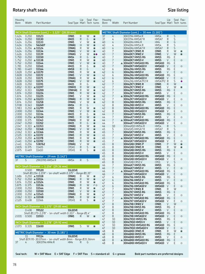
Seal tech: W = SKF Wave E = SKF Edge F = SKF Flex S = standard oil G = grease Bold part numbers are preferred designs
Rotary shaft seals Size listing
HousingBore Width
Part Number Seal Type
Lip Mat'l
Seal Tech
Fea-tures
INCH Shaft Diameter (cont.) – 1.125" (28.58 mm)
. . CRW R W ■
. . HM R G ■
. . CRW V W ■
. . CRWA H W ■
. . ▲ CRWA R W ■
. . CRWA V W ■
. . CRWA V W ■◆
. . HM R G ■
. . ▲ CRW R W ■
. . CRW V W ■
. . HM R G ■
. . HM R G. . ▲ CRW R W ■
. . CRW V W ■
. . CRWA R W ■
. . CRWA V W ■
. . HM R G. . ▲ CRWH R W ■
. . CRWHA R W ■
. . CRW R W ■
. . CRW V W ■
. . ▲ CRWA R W ■
. . CRWA V W ■
. . HM R G. . ▲ CRW R W ■
. . CRW V W ■
. . HM R G ■
. . ▲ CRW R W ■
. . CRWA R W ■
. . HM R G ■
. . ▲ CRWA R W ■
. . CRWA V W ■
. . ▲ CRW R W ■
. . ▲ CRW R W ■
. . ▲ CRW R W ■
. . ▲ CRW R W ■
. . CRWA V W. . CRSA R S ■
. . CRSH R S ■
METRIC Shaft Diameter – 29 mm (1.142")
XX HMS R HMS R S
INCH Shaft Diameter – 1.156" (29.36 mm)
. SSLEEVEShaft Ø.-." - 'on-shaft' width ." - flange Ø."
. . ▲ CRWA R W ■
. . ▲ CRWA R W ■
. . ▲ CRW R W ■
. . CRWA R W ◤◎
. . CRW R W ■
. . CRW V W ■
. . ▲ CRWA R W ■
. . ▲ CRW R W ■
. . CRSH R S ■
INCH Shaft Diameter – 1.175" (29.85 mm)
. SSLEEVEShaft Ø.-." - 'on-shaft' width ." - flange Ø."
. . CRW R W ■
INCH Shaft Diameter – 1.178" (29.92 mm)
. . CRW S W ■
METRIC Shaft Diameter – 30 mm (1.181" )
SSLEEVEShaft Ø.-.mm - 'on-shaft' width mm - flange Ø.mm
XX HM R HM R G
Housing Bore
Width
Part Number
Seal Type
Lip Mat'l
Seal Tech
Fea-tures
METRIC Shaft Diameter (cont.) – 30 mm (1.181")
XX HMS R HMS R S XX HMSA R HMSA R S XX HM R HM R G XX HMS R HMS R S XX HMSA R HMSA R S XX CRW R CRW R W ■
XX CRW V CRW V W ■
XX HMS RG HMS RG E XX HMS V HMS V E ◎
▲ XX HMSA RG HMSA RG E XX HMSA V HMSA V E ◎
XX HMS RG HMS RG E XX HMS V HMS V E ◎
XX HMSA RG HMSA RG E XX HMSA V HMSA V E ◎
XX HMSAP R HMSAP R S ◆
XX CRW R CRW R W XX CRW V CRW V W ■
XX HMS RG HMS RG E XX HMS V HMS V E ◎
▲ XX HMSA RG HMSA RG E XX HMSA V HMSA V E ◎
XX HMS RG HMS RG E XX HMS V HMS V E ◎
XX HMSA RG HMSA RG E XX HMSA V HMSA V E ◎
XX HMS RG HMS RG E XX HMS V HMS V E ◎
▲ XX HMSA RG HMSA RG E XX HMSA V HMSA V E ◎
XX HMS R HMS R S XX HMSA R HMSA R S XX HMS RG HMS RG E XX HMS V HMS V E ◎
▲ XX HMSA RG HMSA RG E XX HMSA V HMSA V E ◎
XX CRW P CRW P W ■
XX CRW R CRW R W ■
XX HMS RG HMS RG E XX HMS V HMS V E ◎
XX HMSA RG HMSA RG E XX HMSA V HMSA V E ◎
XX CRS V CRS V S XX HMS RG HMS RG E XX HMS V HMS V E ◎
▲ XX HMSA RG HMSA RG E XX HMSA V HMSA V E ◎
XX HMS RG HMS RG E XX HMS V HMS V E ◎
XX HMSA RG HMSA RG E XX HMSA V HMSA V E ◎
XX CRW R CRW R W XX HMS RG HMS RG E XX HMS V HMS V E ◎
▲ XX HMSA RG HMSA RG E XX HMSA V HMSA V E ◎
XX CRW V CRW V W XX HMS RG HMS RG E XX HMS V HMS V E ◎
XX HMSA RG HMSA RG E XX HMSA V HMSA V E ◎
XX HMS RG HMS RG E XX HMS V HMS V E ◎
XX HMSA RG HMSA RG E XX HMSA V HMSA V E ◎
XX CRW R CRW R W ■
XX HMS RG HMS RG E XX HMS V HMS V E ◎
▲ XX HMSA RG HMSA RG E XX HMSA V HMSA V E ◎

Rotary shaft seals Size listing
Key features: ▲ WasteWatcher ■ Bore-Tite ◤ SS Case ◎ SS Spring ◆ Pressure seal up to 50 psi ◇ Cover plate required
HousingBore Width
Part Number Seal Type
Lip Mat'l
Seal Tech
Fea-tures
METRIC Shaft Diameter (cont.) – 30 mm (1.181")
XX HMS RG HMS RG E XX HMS V HMS V E ◎
XX HMSA RG HMSA RG E XX HMSA V HMSA V E ◎
XX HMS RG HMS RG E XX HMS V HMS V E ◎
▲ XX HMSA RG HMSA RG E XX HMSA V HMSA V E ◎
XX CRW R CRW R W XX CRW V CRW V W ■
XX HMS RG HMS RG E XX HMS V HMS V E ◎
XX HMSA RG HMSA RG E XX HMSA V HMSA V E ◎
XX HMS RG HMS RG E XX HMS V HMS V E ◎
XX HMSA RG HMSA RG E XX HMSA V HMSA V E ◎
XX HMS RG HMS RG E XX HMS V HMS V E ◎
▲ XX HMSA RG HMSA RG E XX HMSA V HMSA V E ◎
XX CRW R CRW R W XX HMS RG HMS RG E XX HMS V HMS V E ◎
XX HMSA RG HMSA RG E XX HMSA V HMSA V E ◎
XX HMS RG HMS RG E XX HMS V HMS V E ◎
XX HMSA RG HMSA RG E XX HMSA V HMSA V E ◎
XX CRW R CRW R W XX HMS RG HMS RG E XX HMS V HMS V E ◎
▲ XX HMSA RG HMSA RG E XX HMSA V HMSA V E ◎
XX HMS RG HMS RG E XX HMS V HMS V E ◎
XX HMSA RG HMSA RG E XX HMSA V HMSA V E ◎
XX CRW R CRW R W XX CRWA R CRWA R W ■
▲ XX CRW R CRW R W ■
XX HMS R HMS R S XX HMSA R HMSA R S XX CRW R CRW R W XX CRW V CRW V W ■
XX HMS RG HMS RG E XX HMS V HMS V E ◎
▲ XX HMSA RG HMSA RG E XX HMSA V HMSA V E ◎
XX HMS RG HMS RG E XX HMS V HMS V E ◎
XX HMSA RG HMSA RG E XX HMSA V HMSA V E ◎
▲ XX CRW R CRW R W ■
XX HMS RG HMS RG E XX HMS V HMS V E ◎
▲ XX HMSA RG HMSA RG E XX HMSA V HMSA V E ◎
XX CRWA V CRWA V W
INCH Shaft Diameter – 1.188" (30.18 mm)
. SSLEEVEShaft Ø.-." - 'on-shaft' width ." - flange Ø."
. . CRW V W ◤◎
. . HM H G. . CRW P W ■
. . CRW R W ■
. . ▲ CRW R W ■
Housing Bore
Width
Part Number
Seal Type
Lip Mat'l
Seal Tech
Fea-tures
INCH Shaft Diameter (cont.) – 1.188" (30.18 mm)
. . CRW V W ■
. . ▲ CRW R W ■
. . CRW P W ■
. . ▲ CRW R W ■
. . CRW R W ■
. . ▲ CRWA R W ■
. . HD R G. . HM R G ■
. . ▲ CRW R W ■
. . CRW V W ■
. . CRWA R W ■
. . HM R G. . CRW P W ■
. . ▲ CRW R W ■
. . ▲ CRW R W ■
. . CRWHA R W ■
. . ▲ CRW R W ■
. . ▲ CRW R W ■
. . CRW V W ■
. . ▲ CRW R W ■
. . ▲ CRW R W ■
METRIC Shaft Diameter – 31 mm (1.220" )
SSLEEVEShaft Ø.-.mm - 'on-shaft' width .mm - flange Ø.mm
XX HMS V HMS V S . HMS R S . HM R G ■
. . HM R G ■
. . CRSH R S ■
INCH Shaft Diameter – 1.234" (31.34 mm)
. . ▲ CRW R W ■
INCH Shaft Diameter – 1.240" ( 31.50 mm)
. SSLEEVEShaft Ø.-." - 'on-shaft' width ." - flange Ø."
INCH Shaft Diameter – 1.250" ( 31.75 mm)
. SSLEEVEShaft Ø.-.” - ‘on-shaft’ width .” - flange Ø.”
. GSLEEVEShaft Ø.-.” - ‘on-shaft’ width .” - flange Ø.”
. . HM R G ■
. . HM R G ■
. . ▲ CRW R W ■
. . HM R G. . HM R G ■
. . ▲ CRW R W ■
. . CRW V W ■
. . CRWA V W ■
. . CRWA R W ■
. . CRWA R W ■◆
. . CRWA R W ■◆
. . CRWA V W ■◆
. . HM R G ■
. . CRW R W ■
. . CRW V W ■
. . ▲ CRWA R W ■
. . CRWA V W ■
. . HM R G. . HMS R S. . CRW P W ■
. . CRW R W ■
. . ▲ CRWA R W ■
. . CRWA V W ■
. . HM R G ■
. . CRWA V W ◆
. . ▲ CRW R W ■

Seal tech: W = SKF Wave E = SKF Edge F = SKF Flex S = standard oil G = grease Bold part numbers are preferred designs
Rotary shaft seals Size listing
HousingBore Width
Part Number Seal Type
Lip Mat'l
Seal Tech
Fea-tures
INCH Shaft Diameter (cont.) – 1.250" (31.75 mm)
. . CRWA R W ■
. . HM R G. . HM R G ■
. . HM R G ■
. . HM R G ■
. . HM R G. . CRW R W ■
. . CRW V W ■
. . ▲ CRWA R W ■
. . HM R G. . CRWA V W ■◎◆
. . CRW R W ■
. . CRW V W ■
. . ▲ CRWA R W ■
. . CRWA V W ■◎
. . HM R G ■
. . CRW P W ■
. . CRWA R W ■
. . CRWA V W ■
. . HM R G ■
. . CRWHA V W ■
. . ▲ CRWH R W ■
. . ▲ CRW R W ■
. . CRW V W ■
. . CRWA R W ■
. . HM R G ■
. . CRWA V W ■
. . ▲ CRW R W ■
. . HM R G ■
. . ▲ CRW R W ■
. . CRWA R W ■◎◆
. . HM R G ■
. . CRW R W ■
. . ▲ CRWA R W ■
. . CRW V W ■
. . ▲ CRW R W ■
. . ▲ CRW R W ■
. . CRW V W ■
. . ▲ CRW R W ■
. . CRWA R W ■◎◆
. . CRSH R S. . CRSH R S ■
. . CRSH R S
METRIC Shaft Diameter – 32 mm (1.260")
. SSLEEVEShaft Ø.-.mm - 'on-shaft' width mm - flange Ø.mm
. GSLEEVEShaft Ø.-.mm - 'on-shaft' width .mm - flange Ø.mm
XX HMS R HMS R S XX HM R HM R G XX CRW R CRW R W ■
XX CRW V CRW V W ■
XX HMS RG HMS RG E XX HMS V HMS V E ◎
▲ XX HMSA RG HMSA RG E XX HMSA V HMSA V E ◎
XX HMSA R HMSA R S XX HMS RG HMS RG E XX HMS V HMS V E ◎
XX HMSA RG HMSA RG E XX HMSA V HMSA V E ◎
XX HMS RG HMS RG E XX HMS V HMS V E ◎
XX HMSA RG HMSA RG E XX HMSA V HMSA V E ◎
XX HMS R HMS R S XX HMS RG HMS RG E XX HMS V HMS V E ◎
▲ XX HMSA RG HMSA RG E
Housing Bore
Width
Part Number
Seal Type
Lip Mat'l
Seal Tech
Fea-tures
METRIC Shaft Diameter (cont.) – 32 mm (1.260")
XX HMSA V HMSA V E ◎
XX CRW R CRW R W ■
XX HMS RG HMS RG E XX HMS V HMS V E ◎
XX HMSA RG HMSA RG E XX HMSA V HMSA V E ◎
XX CRS R CRS R S XX HMS RG HMS RG E XX HMS V HMS V E ◎
XX HMSA RG HMSA RG E XX HMSA V HMSA V E ◎
XX HMS RG HMS RG E XX HMS V HMS V E ◎
▲ XX HMSA RG HMSA RG E XX HMSA V HMSA V E ◎
XX CRW R CRW R W ■
XX CRW V CRW V W ■
XX HMS RG HMS RG E XX HMS V HMS V E ◎
XX HMSA RG HMSA RG E XX HMSA V HMSA V E ◎
XX HMS RG HMS RG E XX HMS V HMS V E ◎
XX HMSA RG HMSA RG E XX HMSA V HMSA V E ◎
XX HMS R HMS R S XX HMSA R HMSA R S XX HMS R HMS R S XX CRW R CRW R W ■
XX CRW V CRW V W ■
XX HMS RG HMS RG E XX HMS V HMS V E ◎
▲ XX HMSA RG HMSA RG E XX HMSA V HMSA V E ◎
HMSA P S XX CRW R CRW R W ■
XX CRW V CRW V W ■
XX HMS RG HMS RG E XX HMS V HMS V E ◎
▲ XX HMSA RG HMSA RG E XX HMSA V HMSA V E ◎
XX HMS RG HMS RG E XX HMS V HMS V E ◎
XX HMSA RG HMSA RG E XX HMSA V HMSA V E ◎
XX HMS RG HMS RG E XX HMS V HMS V E ◎
▲ XX HMSA RG HMSA RG E XX HMSA V HMSA V E ◎
XX CRW R CRW R W ■
XX CRW V CRW V W ■
XX HMS RG HMS RG E XX HMS V HMS V E ◎
XX HMSA RG HMSA RG E XX HMSA V HMSA V E ◎
XX HMSA R HMSA R S XX HMSA R HMSA R S XX HMSA R HMSA R S XX HMS RG HMS RG E XX HMS V HMS V E ◎
▲ XX HMSA RG HMSA RG E XX HMSA V HMSA V E ◎
XX CRW R CRW R W ■
XX HMS R HMS R S XX HMS R HMS R S XX HMSA R HMSA R S XX HMSA R HMSA R S XX HMS RG HMS RG E XX HMS V HMS V E ◎
▲ XX HMSA RG HMSA RG E
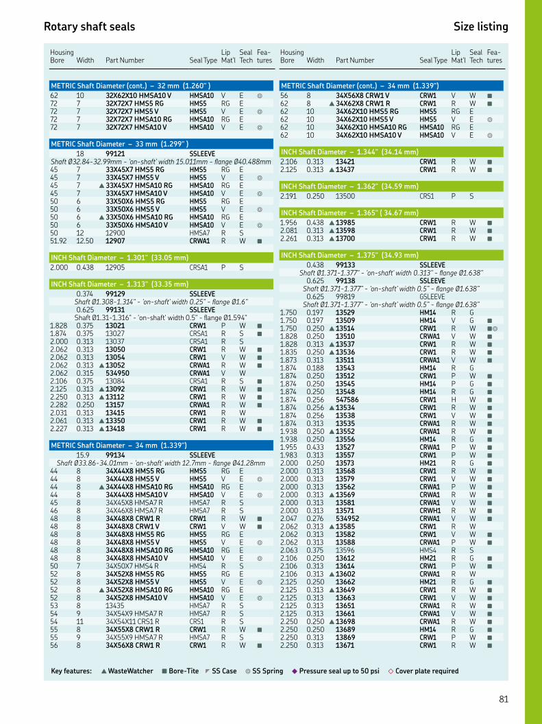
Rotary shaft seals Size listing
Key features: ▲ WasteWatcher ■ Bore-Tite ◤ SS Case ◎ SS Spring ◆ Pressure seal up to 50 psi ◇ Cover plate required
HousingBore Width
Part Number Seal Type
Lip Mat'l
Seal Tech
Fea-tures
METRIC Shaft Diameter (cont.) – 32 mm (1.260" )
XX HMSA V HMSA V E ◎
XX HMS RG HMS RG E XX HMS V HMS V E ◎
XX HMSA RG HMSA RG E XX HMSA V HMSA V E ◎
METRIC Shaft Diameter – 33 mm (1.299" )
SSLEEVEShaft Ø.-.mm - 'on-shaft' width .mm - flange Ø.mm XX HMS RG HMS RG E XX HMS V HMS V E ◎
▲ XX HMSA RG HMSA RG E XX HMSA V HMSA V E ◎
XX HMS RG HMS RG E XX HMS V HMS V E ◎
▲ XX HMSA RG HMSA RG E XX HMSA V HMSA V E ◎
HMSA R S. . CRWA R W ■
INCH Shaft Diameter – 1.301" (33.05 mm)
. . CRSA P S
INCH Shaft Diameter – 1.313" (33.35 mm)
. SSLEEVEShaft Ø.-." - 'on-shaft' width ." - flange Ø.". SSLEEVE
Shaft Ø.-." - 'on-shaft' width ." - flange Ø.". . CRW P W ■
. . CRSA R S ■
. . CRSA R S. . CRW R W ■
. . CRW V W ■
. . ▲ CRWA R W ■
. . CRWA V W. . CRSA R S ■
. . ▲ CRW R W ■
. . ▲ CRW R W ■
. . CRWA R W ■
. . CRW R W. . ▲ CRW R W ■
. . ▲ CRW R W ■
METRIC Shaft Diameter – 34 mm (1.339")
. SSLEEVEShaft Ø.-.mm - 'on-shaft' width .mm - flange Ø.mm
XX HMS RG HMS RG E XX HMS V HMS V E ◎
▲ XX HMSA RG HMSA RG E XX HMSA V HMSA V E ◎
XX HMSA R HMSA R S XX HMSA R HMSA R S XX CRW R CRW R W ■
XX CRW V CRW V W ■
XX HMS RG HMS RG E XX HMS V HMS V E ◎
XX HMSA RG HMSA RG E XX HMSA V HMSA V E ◎
XX HMS R HMS R S XX HMS RG HMS RG E XX HMS V HMS V E ◎
▲ XX HMSA RG HMSA RG E XX HMSA V HMSA V E ◎
HMSA R S XX HMSA R HMSA R S XX CRS R CRS R S XX CRW R CRW R W ■
XX HMSA R HMSA R S XX CRW R CRW R W ■
Housing Bore
Width
Part Number
Seal Type
Lip Mat'l
Seal Tech
Fea-tures
METRIC Shaft Diameter (cont.) – 34 mm (1.339")
XX CRW V CRW V W ■
▲ XX CRW R CRW R W ■
XX HMS RG HMS RG E XX HMS V HMS V E ◎
XX HMSA RG HMSA RG E XX HMSA V HMSA V E ◎
INCH Shaft Diameter – 1.344" (34.14 mm)
. . CRW R W ■
. . ▲ CRW R W ■
INCH Shaft Diameter – 1.362" (34.59 mm)
. . CRS P S
INCH Shaft Diameter – 1.365" ( 34.67 mm)
. . ▲ CRW R W ■
. . ▲ CRW R W ■
. . ▲ CRW R W ■
INCH Shaft Diameter – 1.375" (34.93 mm)
. SSLEEVEShaft Ø.-." - 'on-shaft' width ." - flange Ø."
. SSLEEVEShaft Ø.-.” - ‘on-shaft’ width .” - flange Ø.”
. GSLEEVEShaft Ø.-.” - ‘on-shaft’ width .” - flange Ø.”
. . HM R G. . HM V G ■
. . ▲ CRW R W ■◎
. . CRWA V W ■
. . ▲ CRW R W ■
. . ▲ CRW R W ■
. . CRWA V W ■
. . HM R G. . CRW P W ■
. . HM P G ■
. . HM R G ■
. . CRW H W ■
. . ▲ CRW R W ■
. . CRW V W ■
. . CRWA R W ■
. . ▲ CRWA R W ■
. . HM R G ■
. . CRWA P W ■
. . CRW P W ■
. . HM R G ■
. . CRW R W ■
. . CRW V W ■
. . CRWA P W ■
. . ▲ CRWA R W ■
. . CRWA V W ■
. . CRWH R W ■
. . CRWA V W ■
. . ▲ CRW R W. . CRW V W ■
. . CRWA P W ■
. . HMS R S. . HM R G ■
. . CRW P W ■
. . ▲ CRWA R W. . HM R G ■
. . ▲ CRW R W ■
. . CRW V W ■
. . CRWA R W ■
. . CRWA V W ■
. . ▲ CRWA R W ■
. . HM R G ■
. . CRW P W ■
. . CRW R W ■

Seal tech: W = SKF Wave E = SKF Edge F = SKF Flex S = standard oil G = grease Bold part numbers are preferred designs
Rotary shaft seals Size listing
HousingBore Width
Part Number Seal Type
Lip Mat'l
Seal Tech
Fea-tures
INCH Shaft Diameter (cont.) – 1.375" (34.93 mm)
. . CRW V W ■
. . CRWA R W ■
. . CRWA V W ■
. . HM R G ■
. . HM R G. . HM R G ■
. . CRW R W ■
. . CRW V W ■
. . ▲ CRWA R W ■
. . ▲ CRW R W ■
. . HM R G ■
. . HM R G ■
. . ▲ CRW R W ■
. . CRW V W ■
. . CRW R W ■
. . ▲ CRWA R W ■
. . CRWA V W ■
. . CRWA V W ■
. . ▲ CRW R W ■
. . CRWA R W. . ▲ CRW R W ■
. . CRSH R S ■
. . ▲ CRWHA R W ■
. . CRWA P W ■
. . CRSHA R S. . CRSH R S. . CRSH R S ■
METRIC Shaft Diameter – 35 mm (1.378")
SSLEEVEShaft Ø.-.mm - ‘on-shaft’ width mm - flange Ø.mm
GSLEEVEShaft Ø.-.mm - ‘on-shaft’ width mm - flange Ø.mm
XX HM R HM R G XX HM R HM R G XX HMS RG HMS RG E XX HMS V HMS V E ◎
▲ XX HMSA RG HMSA RG E XX HMSA V HMSA V E ◎
XX HMSA R HMSA R S XX HM R HM R G XX HMS R HMS R S XX HMS RG HMS RG E XX HMS V HMS V E ◎
XX HMSA RG HMSA RG E XX HMSA V HMSA V E ◎
XX CRW R CRW R W ■
XX CRW V CRW V W ■◎
CRWA V W ■
XX HMS RG HMS RG E XX HMS V HMS V E ◎
▲ XX HMSA RG HMSA RG E XX HMSA V HMSA V E ◎
XX HMS RG HMS RG E XX HMS V HMS V E ◎
XX HMSA RG HMSA RG E XX HMSA V HMSA V E ◎
XX CRW R CRW R W ■
XX CRW V CRW V W ■
XX HMS RG HMS RG E XX HMS V HMS V E ◎
▲ XX HMSA RG HMSA RG E XX HMSA V HMSA V E ◎
XX HMS RG HMS RG E XX HMS V HMS V E ◎
▲ XX HMSA RG HMSA RG E XX HMSA V HMSA V E ◎
XX HMS RG HMS RG E XX HMS V HMS V E ◎
▲ XX HMSA RG HMSA RG E
Housing Bore
Width
Part Number
Seal Type
Lip Mat'l
Seal Tech
Fea-tures
METRIC Shaft Diameter (cont.) – 35 mm (1.378")
XX HMSA V HMSA V E ◎
XX CRW R CRW R W ■
XX CRW V CRW V W ■
XX HMS RG HMS RG E XX HMS V HMS V E ◎
XX HMSA RG HMSA RG E XX HMSA V HMSA V E ◎
XX HMS RG HMS RG E XX HMS V HMS V E ◎
XX HMSA RG HMSA RG E XX HMSA V HMSA V E ◎
HMS P S XX HMSAP R HMSAP R S ◆
XX HMSAP V HMSAP V S ◆
XX HMS RG HMS RG E XX HMS V HMS V E ◎
▲ XX HMSA RG HMSA RG E XX HMSA V HMSA V E ◎
XX CRW R CRW R W ■
XX CRWA P CRWA P W ■
XX CRWA R CRWA R W XX HMS RG HMS RG E XX HMS V HMS V E ◎
XX HMSA RG HMSA RG E XX HMSA V HMSA V E ◎
XX HMS R HMS R S XX HMS RG HMS RG E XX HMS V HMS V E ◎
XX HMSA RG HMSA RG E XX HMSA V HMSA V E ◎
▲ XX CRW R CRW R W ■
XX CRW V CRW V W ■
XX CRW V CRW V W XX HMS RG HMS RG E XX HMS V HMS V E ◎
▲ XX HMSA RG HMSA RG E XX HMSA V HMSA V E ◎
XX CRW R CRW R W ■
XX CRW V CRW V W XX HMS RG HMS RG E XX HMS V HMS V E ◎
XX HMSA RG HMSA RG E XX HMSA V HMSA V E ◎
XX HMS RG HMS RG E XX HMS V HMS V E ◎
XX HMSA RG HMSA RG E XX HMSA V HMSA V E ◎
XX HMSA R HMSA R S XX CRW R CRW R W ■
XX CRW V CRW V W ■
XX HMS RG HMS RG E XX HMS V HMS V E ◎
▲ XX HMSA RG HMSA RG E XX HMSA V HMSA V E ◎
XX HMS RG HMS RG E XX HMS V HMS V E ◎
▲ XX HMSA RG HMSA RG E XX HMSA V HMSA V E ◎
XX HMS RG HMS RG E XX HMS V HMS V E ◎
▲ XX HMSA RG HMSA RG E XX HMSA V HMSA V E ◎
XX HMSA R HMSA R S XX HMS RG HMS RG E XX HMS V HMS V E ◎
▲ XX HMSA RG HMSA RG E XX HMSA V HMSA V E ◎
. XX. HMS RG HMS RG E . XX. HMS V HMS V E ◎
. XX. HMSA RG HMSA RG E

Rotary shaft seals Size listing
Key features: ▲ WasteWatcher ■ Bore-Tite ◤ SS Case ◎ SS Spring ◆ Pressure seal up to 50 psi ◇ Cover plate required
HousingBore Width
Part Number Seal Type
Lip Mat'l
Seal Tech
Fea-tures
METRIC Shaft Diameter (cont.) – 35 mm (1.378")
. XX. HMSA V HMSA V E ◎
. CRW R W ■
. CRWA R W ■
XX CRW R CRW R W ■
XX CRW V CRW V W ■
XX HMS RG HMS RG E XX HMS V HMS V E ◎
XX HMSA RG HMSA RG E XX HMSA V HMSA V E ◎
XX HMS RG HMS RG E XX HMS V HMS V E ◎
XX HMSA RG HMSA RG E XX HMSA V HMSA V E ◎
XX CRW R CRW R W ■
XX CRW R CRW R W ■
XX HMS R HMS R S XX CRW R CRW R W ■
XX CRW V CRW V W ■
XX HMS R HMS R S XX HMS RG HMS RG E XX HMS V HMS V E ◎
▲ XX HMSA RG HMSA RG E XX HMSA V HMSA V E ◎
. CRW R W ■
. CRWA P W ■
. CRWA R W ■
. CRWA V W ■◎
XX CRW R CRW R W ■
XX CRW V CRW V W ■
XX HMS RG HMS RG E XX HMS V HMS V E ◎
XX HMSA RG HMSA RG E XX HMSA V HMSA V E ◎
XX HMS RG HMS RG E XX HMS V HMS V E ◎
XX HMSA RG HMSA RG E XX HMSA V HMSA V E ◎
XX CRW R CRW R W ■
▲ XX CRW R CRW R W ■
XX HMS RG HMS RG E XX HMS V HMS V E ◎
▲ XX HMSA RG HMSA RG E XX HMSA V HMSA V E ◎
INCH Shaft Diameter – 1.399" (35.53 mm)
. . ▲ CRW R W
INCH Shaft Diameter – 1.414" (35.92 mm)
. . CRSA R S ■
METRIC Shaft Diameter – 36 mm (1.417")
SSLEEVEShaft Ø.-.mm - 'on-shaft' width mm - flange Ø.mm
XX HMSA R HMSA R S XX HMS RG HMS RG E XX HMS V HMS V E ◎
▲ XX HMSA RG HMSA RG E XX HMSA V HMSA V E ◎
XX CRW R CRW R W ■
XX HMS RG HMS RG E XX HMS V HMS V E ◎
▲ XX HMSA RG HMSA RG E XX HMSA V HMSA V E ◎
XX CRW R CRW R W ■
XX HMS RG HMS RG E XX HMS V HMS V E ◎
▲ XX HMSA RG HMSA RG E XX HMSA V HMSA V E ◎
XX CRW R CRW R W ■
Housing Bore
Width
Part Number
Seal Type
Lip Mat'l
Seal Tech
Fea-tures
METRIC Shaft Diameter (cont.) – 36 mm (1.417")
XX CRW V CRW V W ■
XX CRW R CRW R W ■
XX CRW V CRW V W ■
XX HMS R HMS R S XX HMS R HMS R S XX CRW R CRW R W ■
XX HMS RG HMS RG E XX HMS V HMS V E ◎
▲ XX HMSA RG HMSA RG E XX HMSA V HMSA V E ◎
XX HMS R HMS R S XX CRW R CRW R W ■
XX CRW V CRW V W ■
XX HMS RG HMS RG E XX HMS V HMS V E ◎
▲ XX HMSA RG HMSA RG E XX HMSA V HMSA V E ◎
XX CRW R CRW R W ■
XX CRW R CRW R W ■
. . CRW R W ■
XX CRW R CRW R W ■
XX HMS R HMS R S
INCH Shaft Diameter – 1.435" (36.45 mm)
. SSLEEVEShaft Ø.-.” - ‘on-shaft’ width .” - flange Ø.”
. GSLEEVEShaft Ø.-." - 'on-shaft' width ." - flange Ø."
INCH Shaft Diameter – 1.438" (36.53 mm)
. SSLEEVEShaft Ø.-.” - ‘on-shaft’ width .” - flange Ø.”
. . HM R G. . CRW V W. . ▲ CRWA R W ■
. . ▲ CRW R W ■
. . CRWA V W ■
. . HM R G ■
. . CRW R W ■
. . CRW V W ■
. . ▲ CRWA R W ■
. . CRWA V W ■
. . ▲ CRW R W ■
. . CRWA R W ■
. . HM R G ■
. . ▲ CRW R W ■
. . ▲ CRW R W ■
. . ▲ CRW R W ■
. . ▲ CRW R W ■
. . ▲ CRW R W ■
METRIC Shaft Diameter – 37 mm (1.457")
XX HM R HM R G XX HMS R HMS R S XX HMSA R HMSA R S XX HMS RG HMS RG E XX HMS V HMS V E ◎
▲ XX HMSA RG HMSA RG E XX HMSA V HMSA V E ◎
XX HMSA P HMSA P S XX HMS R HMS R S
INCH Shaft Diameter – 1.469" (37.31 mm)
. . CRSA R S
INCH Shaft Diameter – 1.484" (37.69 mm)
. . ▲ CRW R W ■

Seal tech: W = SKF Wave E = SKF Edge F = SKF Flex S = standard oil G = grease Bold part numbers are preferred designs
Rotary shaft seals Size listing
HousingBore Width
Part Number Seal Type
Lip Mat'l
Seal Tech
Fea-tures
INCH Shaft Diameter – 1.491" (37.87 mm)
. . CRSA R S
INCH Shaft Diameter – 1.494" (37.95 mm)
. . CRW R W ■
METRIC Shaft Diameter – 38 mm (1.496")
SSLEEVEShaft Ø.-mm - ‘on-shaft’ width mm - flange Ø.mm
XX HM R HM R G XX CRW R CRW R W ■
XX CRW V CRW V W ■
XX HMS RG HMS RG E XX HMS V HMS V E ◎
▲ XX HMSA RG HMSA RG E XX HMSA V HMSA V E ◎
XX HMS RG HMS RG E XX HMS V HMS V E ◎
▲ XX HMSA RG HMSA RG E XX HMSA V HMSA V E ◎
XX CRW R CRW R W ■
XX CRW V CRW V W ■
XX CRWA R CRWA R W ■
XX HMS RG HMS RG E XX HMS V HMS V E ◎
XX HMSA RG HMSA RG E XX HMSA V HMSA V E ◎
XX CRW R CRW R W ■
XX CRW P CRW P W XX HMS RG HMS RG E XX HMS V HMS V E ◎
▲ XX HMSA RG HMSA RG E XX HMSA V HMSA V E ◎
XX HMS RG HMS RG E XX HMS V HMS V E ◎
▲ XX HMSA RG HMSA RG E XX HMSA V HMSA V E ◎
XX CRW R CRW R W ■
XX CRW V CRW V W ■
XX HMS RG HMS RG E XX HMS V HMS V E ◎
XX HMSA RG HMSA RG E XX HMSA V HMSA V E ◎
XX HMS RG HMS RG E XX HMS V HMS V E ◎
XX HMSA RG HMSA RG E XX HMSA V HMSA V E ◎
XX CRW R CRW R W ■
XX CRW V CRW V W ■
XX HMS R HMS R S. . HMSA P S XX CRW R CRW R W ■
XX CRW V CRW V W ■
XX HMS RG HMS RG E XX HMS V HMS V E ◎
▲ XX HMSA RG HMSA RG E XX HMSA V HMSA V E ◎
XX HMS RG HMS RG E XX HMS V HMS V E ◎
XX HMSA RG HMSA RG E XX HMSA V HMSA V E ◎
▲ XX CRW R CRW R W ■
XX CRW V CRW V W ■
XX HMS RG HMS RG E XX HMS V HMS V E ◎
▲ XX HMSA RG HMSA RG E XX HMSA V HMSA V E ◎
XX HMS RG HMS RG E XX HMS V HMS V E ◎
▲ XX HMSA RG HMSA RG E
Housing Bore
Width
Part Number
Seal Type
Lip Mat'l
Seal Tech
Fea-tures
METRIC Shaft Diameter (cont.) – 38 mm (1.496")
XX HMSA V HMSA V E ◎
XX CRW R CRW R W ■
XX CRW V CRW V W ■
XX HMS RG HMS RG E XX HMS V HMS V E ◎
XX HMSA RG HMSA RG E XX HMSA V HMSA V E ◎
XX HMS RG HMS RG E XX HMS V HMS V E ◎
XX HMSA RG HMSA RG E XX HMSA V HMSA V E ◎
XX HMS RG HMS RG E XX HMS V HMS V E ◎
▲ XX HMSA RG HMSA RG E XX HMSA V HMSA V E ◎
XX CRW R CRW R W ■
XX HMS R HMS R S XX HMS RG HMS RG E XX HMS V HMS V E ◎
▲ XX HMSA RG HMSA RG E XX HMSA V HMSA V E ◎
XX CRW V CRW V W ■
XX CRWA R CRWA R W ■
▲ XX CRW R CRW R W ■
XX HMS RG HMS RG E XX HMS V HMS V E ◎
XX HMSA RG HMSA RG E XX HMSA V HMSA V E ◎
XX CRWA R CRWA R W ■
XX HMS RG HMS RG E XX HMS V HMS V E ◎
XX HMSA RG HMSA RG E XX HMSA V HMSA V E ◎
INCH Shaft Diameter – 1.500" (38.10 mm)
. SSLEEVEShaft Ø.-.” - ‘on-shaft’ width .” - flange Ø.”
. GSLEEVEShaft Ø.-.” - ‘on-shaft’ width .” - flange Ø.”
. SSLEEVEShaft Ø.-.” - ‘on-shaft’ width .” - flange Ø.”
. GSLEEVEShaft Ø.-.” - ‘on-shaft’ width .” - flange Ø.”
. . HM R G. . HM V G ■
. . ▲ CRW R W ◎
. . HM R G ■
. . HM R G ■
. . HM R G. . CRW V W ■
. . CRWA R W ■
. . CRWA V W ■
. . CRW R W ■
. . CRWA V W ■◎◆
. . HM R G ■
. . ▲ CRW R W ■
. . CRW V W ■
. . CRW V W ◤◎
. . CRWA R W ■
. . ▲ CRWA R W ■
. . HM R G ■
. . ▲ CRW R W ■
. . CRW V W ■
. . CRWA V W ■◎◆
. . CRW R W ■
. . CRW V W ■
. . ▲ CRWA R W ■
. . CRWA V W ■
. . CRW R W ■
. . HM R G

Rotary shaft seals Size listing
Key features: ▲ WasteWatcher ■ Bore-Tite ◤ SS Case ◎ SS Spring ◆ Pressure seal up to 50 psi ◇ Cover plate required
HousingBore Width
Part Number Seal Type
Lip Mat'l
Seal Tech
Fea-tures
INCH Shaft Diameter (cont.) – 1.500" (38.10 mm)
. . CRW R W ■
. . CRW V W ■
. . ▲ CRWA R W ■
. . CRWA V W ■
. . CRW S W ■
. . CRWH R W ■
. . HM R G ■
. . ▲ CRW R W ■
. . CRWA V W ■◎◆
. . HM R G. . CRWA R W ■◎◆
. . HM R G ■
. . HM R G. . HM R G ■
. . CRW R W ■
. . CRW V W ■
. . ▲ CRWA R W ■
. . CRWA V W ■
. . CRWH R W ■
. . ▲ CRWA R W ■
. . HM R G ■
. . ▲ CRW R W ■
. . CRW R W. . CRW V W ■
. . ▲ CRWA R W ■
. . HM R G ■
. . CRW R W ■
. . CRW V W ■
. . ▲ CRWA R W ■
. . ▲ CRW R W ■
. . HM R G. . ▲ CRW R W ■
. . ▲ CRW R W ■
. . HM R G ■
. . ▲ CRW R W ■
. . CRWA R W. . ▲ CRW R W ■
. . ▲ CRW R W ■
. . ▲ CRW R W ■
. . ▲ CRW R W ■
. . CRSH R S. . CRSA R S
METRIC Shaft Diameter – 38.50 mm (1.516")
.XX HMS RG HMS RG E .XX HMS V HMS V E ◎
.XX HMSA RG HMSA RG E .XX HMSA V HMSA V E ◎
INCH Shaft Diameter – 1.523" (38.68 mm)
. SSLEEVEShaft Ø.-." - 'on-shaft' width ." - flange Ø."
INCH Shaft Diameter – 1.524" (38.71 mm)
. . CRSH R S ■
METRIC Shaft Diameter – 39 mm (1.535")
. HMA R G
INCH Shaft Diameter – 1.552" (39.42 mm)
. SSLEEVEShaft Ø.-." - 'on-shaft' width ." - flange Ø."
. . ▲ CRWA R W ■
. . ▲ CRW R W ■
. . CRWHA P W ■
Housing Bore
Width
Part Number
Seal Type
Lip Mat'l
Seal Tech
Fea-tures
INCH Shaft Diameter – 1.563" (39.70 mm)
. SSLEEVEShaft Ø.-." - 'on-shaft' width ." - flange Ø."
. GSLEEVEShaft Ø.-." - 'on-shaft' width ." - flange Ø."
. . CRWA V W ■
. . HM R G ■
. . ▲ CRW R W ■
. . CRW V W ■
. . ▲ CRW R W. . CRWA P W ■
. . HM R G ■
. . ▲ CRW R W ■
. . CRWA R W. . HM R G ■
. . CRW P W ■
. . ▲ CRW R W ■
. . CRWA R W ■
. . CRWA V W ■
. . ▲ CRW R W. . ▲ CRWA R W ■
. . CRWA V W ■
. . CRWA P W ■
. . HM R G ■
. . CRW R W ■
. . CRW V W ■
. . ▲ CRWA R W ■
. . ▲ CRW R W ■
. . ▲ CRW R W ■
. . ▲ CRW R W ■
. . HM R G ■
. . HM R G ■
. . ▲ CRWH R W ■
. . ▲ CRW R W ■
. . CRWA P W ■
INCH Shaft Diameter – 1.569" (39.85 mm)
. SSLEEVEShaft Ø.-." - 'on-shaft' width ." - flange Ø."
METRIC Shaft Diameter – 40 mm (1.575" )
. SSLEEVEShaft Ø.-.mm - ‘on-shaft’ width .mm - flange Ø.mm
SSLEEVEShaft Ø.-.mm - ‘on-shaft’ width mm - flange Ø.mm
GSLEEVEShaft Ø.-.mm - ‘on-shaft’ width .mm - flange Ø.mm
XX HMS R HMS R S XX HMSA R HMSA R S XX HM R HM R G XX HM R HM R G XX HMSA R HMSA R S XX HMS RG HMS RG E XX HMS V HMS V E ◎
▲ XX HMSA RG HMSA RG E XX HMSA V HMSA V E ◎
XX HM R HM R G XX HMS RG HMS RG E XX HMS V HMS V E ◎
XX HMSA RG HMSA RG E XX HMSA V HMSA V E ◎
XX CRW R CRW R W ■
XX CRW V CRW V W ■◎
XX HMS RG HMS RG E XX HMS V HMS V E ◎
▲ XX HMSA RG HMSA RG E XX HMSA V HMSA V E ◎
XX HMS RG HMS RG E XX HMS V HMS V E ◎
XX HMSA RG HMSA RG E

Seal tech: W = SKF Wave E = SKF Edge F = SKF Flex S = standard oil G = grease Bold part numbers are preferred designs
Rotary shaft seals Size listing
Housing Bore
Width
Part Number
Seal Type
Lip Mat'l
Seal Tech
Fea-tures
METRIC Shaft Diameter (cont.) – 40 mm (1.575")
XX HMSA V HMSA V E ◎
. . CRW R W ■
▲ XX CRW R CRW R W ■
HMSA P S XX HMS RG HMS RG E XX HMS V HMS V E ◎
▲ XX HMSA RG HMSA RG E XX HMSA V HMSA V E ◎
XX CRW R CRW R W ■
XX CRW V CRW V W ■
XX HMS RG HMS RG E XX HMS V HMS V E ◎
XX HMSA RG HMSA RG E XX HMSA V HMSA V E ◎
XX CRW V CRW V W ■
XX CRW R CRW R W ■
XX HMS RG HMS RG E XX HMS V HMS V E ◎
▲ XX HMSA RG HMSA RG E XX HMSA V HMSA V E ◎
▲ XX CRW R CRW R W ■
HMSA P S XX HMS RG HMS RG E XX HMS V HMS V E ◎
▲ XX HMSA RG HMSA RG E XX HMSA V HMSA V E ◎
XX CRW R CRW R W ■
XX CRW V CRW V W ■
XX HMS RG HMS RG E XX HMS V HMS V E ◎
XX HMSA RG HMSA RG E XX HMSA V HMSA V E ◎
XX HMSA R HMSA R S XX HMS RG HMS RG E XX HMS V HMS V E ◎
XX HMSA RG HMSA RG E XX HMSA V HMSA V E ◎
XX HMS RG HMS RG E XX HMS V HMS V E ◎
XX HMSA RG HMSA RG E XX HMSA V HMSA V E ◎
XX CRW R CRW R W ■
XX CRW V CRW V W ■
XX HMS RG HMS RG E XX HMS V HMS V E ◎
▲ XX HMSA RG HMSA RG E XX HMSA V HMSA V E ◎
XX HMS RG HMS RG E XX HMS V HMS V E ◎
XX HMSA RG HMSA RG E XX HMSA V HMSA V E ◎
XX CRSA R CRSA R S XX HMS R HMS R S. . CRWHA R W ■
XX HMS RG HMS RG E XX HMS V HMS V E ◎
XX HMSA RG HMSA RG E XX HMSA V HMSA V E ◎
XX HMSAP R HMSAP R S ◆
XX HMS RG HMS RG E XX HMS V HMS V E ◎
▲ XX HMSA RG HMSA RG E XX HMSA V HMSA V E ◎
XX CRW R CRW R W ■
XX CRW V CRW V W ■
XX HMS RG HMS RG E XX HMS V HMS V E ◎
XX HMSA RG HMSA RG E
Housing Bore
Width
Part Number
Seal Type
Lip Mat'l
Seal Tech
Fea-tures
METRIC Shaft Diameter (cont.) – 40 mm (1.575")
XX HMSA V HMSA V E ◎
XX HMS RG HMS RG E XX HMS V HMS V E ◎
XX HMSA RG HMSA RG E XX HMSA V HMSA V E ◎
. XX. HMS R HMS R S. HMSA R S XX CRW R CRW R W ■
XX HMS RG HMS RG E XX HMS V HMS V E ◎
▲ XX HMSA RG HMSA RG E XX HMSA V HMSA V E ◎
XX HMS RG HMS RG E XX HMS V HMS V E ◎
XX HMSA RG HMSA RG E XX HMSA V HMSA V E ◎
XX CRW R CRW R W ■
XX HMS RG HMS RG E XX HMS V HMS V E ◎
▲ XX HMSA RG HMSA RG E XX HMSA V HMSA V E ◎
XX HMS RG HMS RG E XX HMS V HMS V E ◎
XX HMSA RG HMSA RG E XX HMSA V HMSA V E ◎
XX CRW R CRW R W ■
XX HMS RG HMS RG E XX HMS V HMS V E ◎
▲ XX HMSA RG HMSA RG E XX HMSA V HMSA V E ◎
XX HMS RG HMS RG E XX HMS V HMS V E ◎
▲ XX HMSA RG HMSA RG E XX HMSA V HMSA V E ◎
XX CRW R CRW R W ■
XX HMS RG HMS RG E XX HMS V HMS V E ◎
XX HMSA RG HMSA RG E XX HMSA V HMSA V E ◎
XX CRW R CRW R W ■
XX CRW V CRW V W ■
XX HMSA R HMSA R S XX HMS RG HMS RG E XX HMS V HMS V E ◎
▲ XX HMSA RG HMSA RG E XX HMSA V HMSA V E ◎
XX CRW R CRW R W ■
XX HMS RG HMS RG E XX HMS V HMS V E ◎
XX HMSA RG HMSA RG E XX HMSA V HMSA V E ◎
XX HMS RG HMS RG E XX HMS V HMS V E ◎
XX HMSA RG HMSA RG E XX HMSA V HMSA V E ◎
XX HMS RG HMS RG E XX HMS V HMS V E ◎
XX HMSA RG HMSA RG E XX HMSA V HMSA V E ◎
XX CRW R CRW R W ■
XX HMS RG HMS RG E XX HMS V HMS V E ◎
▲ XX HMSA RG HMSA RG E XX HMSA V HMSA V E ◎
XX HMS RG HMS RG E XX HMS V HMS V E ◎
XX HMSA RG HMSA RG E XX HMSA V HMSA V E ◎
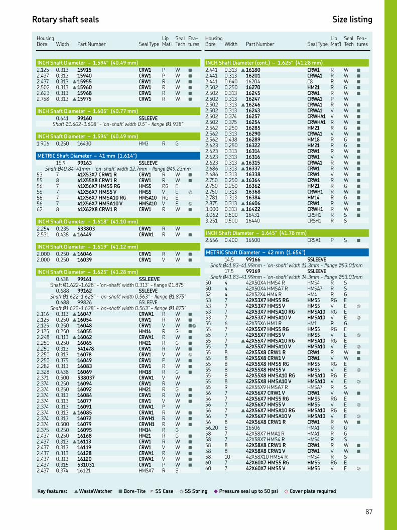
Rotary shaft seals Size listing
Key features: ▲ WasteWatcher ■ Bore-Tite ◤ SS Case ◎ SS Spring ◆ Pressure seal up to 50 psi ◇ Cover plate required
HousingBore Width
Part Number Seal Type
Lip Mat'l
Seal Tech
Fea-tures
INCH Shaft Diameter – 1.594" (40.49 mm)
. . CRW P W ■
. . CRW P W ■
. . ▲ CRW R W ■
. . ▲ CRW R W ■
. . CRW R W ■
. . ▲ CRW R W ■
INCH Shaft Diameter – 1.605" (40.77 mm)
. SSLEEVEShaft Ø.-." - 'on-shaft' width ." - flange Ø."
INCH Shaft Diameter – 1.594" (40.49 mm)
. . HM R G
METRIC Shaft Diameter – 41 mm (1.614")
. SSLEEVEShaft Ø.-mm - 'on-shaft' width .mm - flange Ø.mm
XX CRW R CRW R W ■
XX CRW R CRW R W ■
XX HMS RG HMS RG E XX HMS V HMS V E ◎
XX HMSA RG HMSA RG E XX HMSA V HMSA V E ◎
XX CRW R CRW R W ■
INCH Shaft Diameter – 1.618" (41.10 mm)
. . CRW R W. . ▲ CRWA R W ■
INCH Shaft Diameter – 1.619" (41.12 mm)
. . ▲ CRW R W ■
. . CRW V W ■
INCH Shaft Diameter – 1.625" (41.28 mm)
. SSLEEVEShaft Ø.-." - 'on-shaft' width ." - flange Ø."
. SSLEEVEShaft Ø.-." - 'on-shaft' width ." - flange Ø."
. GSLEEVEShaft Ø.-." - 'on-shaft' width ." - flange Ø."
. . ▲ CRWA R W ■
. . ▲ CRW R W ■
. . CRW V W ■◎
. . HM R G ■
. . ▲ CRWA R W ■
. . HM R G ■
. . CRW R W ■
. . CRW V W ◎
. . CRW P W ■
. . CRW R W ■
. . HM R G ■
. . CRWA V W. . CRW R W. . HM R G ■
. . CRW R W ■
. . CRW V W ■
. . CRWA P W. . ▲ CRWA R W ■
. . CRWH R W ■
. . CRWH R W ■
. . HM R G. . HM R G ■
. . ▲ CRW R W ■
. . CRW V W ■
. . CRWA R W ■
. . CRWA V W ■
. . CRW P W ■
. . HMSA R S
Housing Bore
Width
Part Number
Seal Type
Lip Mat'l
Seal Tech
Fea-tures
INCH Shaft Diameter (cont.) – 1.625" (41.28 mm)
. . ▲ CRW R W ■
. . CRWA R W ■
. . C R W ■
. . HM R G ■
. . CRW R W ■
. . CRWA P W. . ▲ CRWA R W ■
. . CRWA V W ■
. . CRWHA V W ■
. . CRWHA R W ■
. . HM R G ■
. . CRWA V W ■
. . HM R G ■
. . HM R G ■
. . CRW R W ■
. . CRW V W ■
. . ▲ CRWA R W ■
. . ▲ CRW R W ■
. . CRW V W ■
. . ▲ CRW R W ■
. . HM R G ■
. . CRWH R W ■
. . HM R G ■
. . ▲ CRW R W ■
. . ▲ CRWH R W ■
. . CRSH R S ■
. . CRSH R S
INCH Shaft Diameter – 1.645" (41.78 mm)
. . CRSA P S ■
METRIC Shaft Diameter – 42 mm (1.654")
. SSLEEVEShaft Ø.-.mm - 'on-shaft' width .mm - flange Ø.mm
. SSLEEVEShaft Ø.-.mm - 'on-shaft' width .mm - flange Ø.mm
XX HMS R HMS R S XX HMSA R HMSA R S XX HM R HM R G XX HMS RG HMS RG E XX HMS V HMS V E ◎
XX HMSA RG HMSA RG E XX HMSA V HMSA V E ◎
XX HM R HM R G XX HMS RG HMS RG E XX HMS V HMS V E ◎
▲ XX HMSA RG HMSA RG E XX HMSA V HMSA V E ◎
XX CRW R CRW R W ■
XX CRW V CRW V W ■
XX HMS RG HMS RG E XX HMS V HMS V E ◎
XX HMSA RG HMSA RG E XX HMSA V HMSA V E ◎
XX HMSA R HMSA R S XX CRW V CRW V W ■
XX HMS RG HMS RG E XX HMS V HMS V E ◎
▲ XX HMSA RG HMSA RG E XX HMSA V HMSA V E ◎
XX CRW R CRW R W ■
. HMA R G XX HMA R HMA R G XX HMS R HMS R S XX CRW R CRW R W ■
XX CRW V CRW V W ■
XX HMS R HMS R S XX HMS RG HMS RG E XX HMS V HMS V E ◎
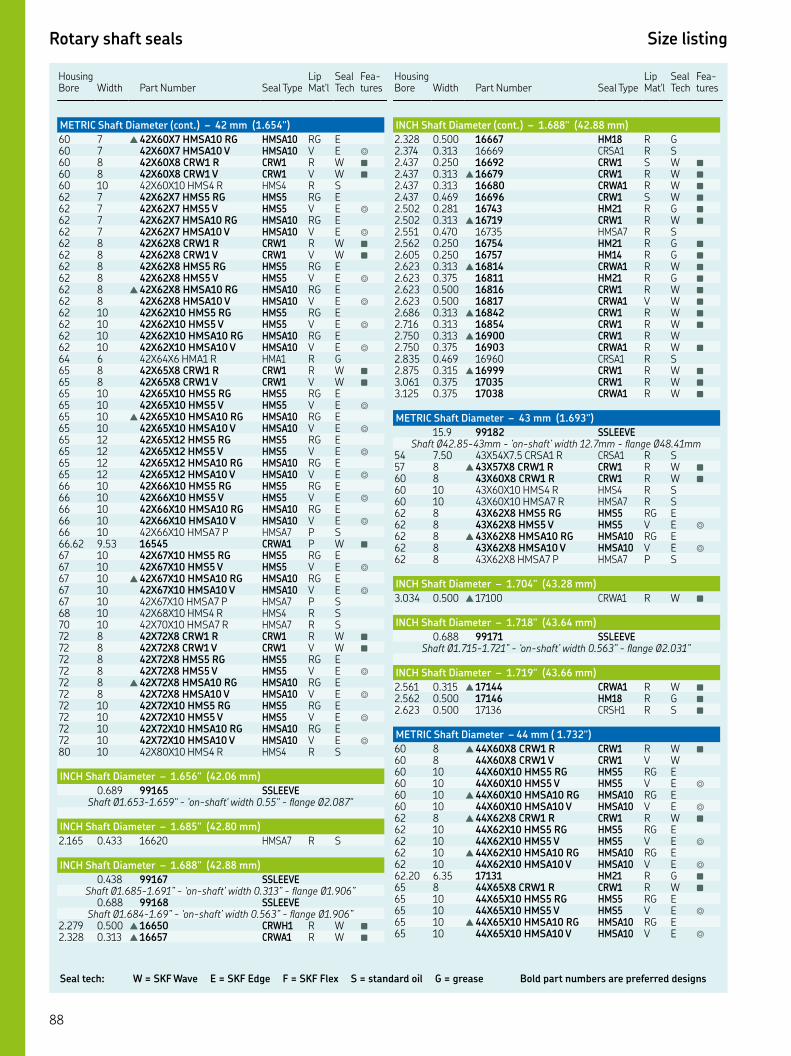
Seal tech: W = SKF Wave E = SKF Edge F = SKF Flex S = standard oil G = grease Bold part numbers are preferred designs
Rotary shaft seals Size listing
Housing Bore
Width
Part Number
Seal Type
Lip Mat'l
Seal Tech
Fea-tures
METRIC Shaft Diameter (cont.) – 42 mm (1.654")
▲ XX HMSA RG HMSA RG E XX HMSA V HMSA V E ◎
XX CRW R CRW R W ■
XX CRW V CRW V W ■
XX HMS R HMS R S XX HMS RG HMS RG E XX HMS V HMS V E ◎
XX HMSA RG HMSA RG E XX HMSA V HMSA V E ◎
XX CRW R CRW R W ■
XX CRW V CRW V W ■
XX HMS RG HMS RG E XX HMS V HMS V E ◎
▲ XX HMSA RG HMSA RG E XX HMSA V HMSA V E ◎
XX HMS RG HMS RG E XX HMS V HMS V E ◎
XX HMSA RG HMSA RG E XX HMSA V HMSA V E ◎
XX HMA R HMA R G XX CRW R CRW R W ■
XX CRW V CRW V W ■
XX HMS RG HMS RG E XX HMS V HMS V E ◎
▲ XX HMSA RG HMSA RG E XX HMSA V HMSA V E ◎
XX HMS RG HMS RG E XX HMS V HMS V E ◎
XX HMSA RG HMSA RG E XX HMSA V HMSA V E ◎
XX HMS RG HMS RG E XX HMS V HMS V E ◎
XX HMSA RG HMSA RG E XX HMSA V HMSA V E ◎
XX HMSA P HMSA P S. . CRWA P W ■
XX HMS RG HMS RG E XX HMS V HMS V E ◎
▲ XX HMSA RG HMSA RG E XX HMSA V HMSA V E ◎
XX HMSA P HMSA P S XX HMS R HMS R S XX HMSA R HMSA R S XX CRW R CRW R W ■
XX CRW V CRW V W ■
XX HMS RG HMS RG E XX HMS V HMS V E ◎
▲ XX HMSA RG HMSA RG E XX HMSA V HMSA V E ◎
XX HMS RG HMS RG E XX HMS V HMS V E ◎
XX HMSA RG HMSA RG E XX HMSA V HMSA V E ◎
XX HMS R HMS R S
INCH Shaft Diameter – 1.656" (42.06 mm)
. SSLEEVEShaft Ø.-." - 'on-shaft' width ." - flange Ø."
INCH Shaft Diameter – 1.685" (42.80 mm)
. . HMSA R S
INCH Shaft Diameter – 1.688" (42.88 mm)
. SSLEEVEShaft Ø.-.” - ‘on-shaft’ width .” - flange Ø.”
. SSLEEVEShaft Ø.-.” - ‘on-shaft’ width .” - flange Ø.”
. . ▲ CRWH R W ■
. . ▲ CRWA R W ■
Housing Bore
Width
Part Number
Seal Type
Lip Mat'l
Seal Tech
Fea-tures
INCH Shaft Diameter (cont.) – 1.688" (42.88 mm)
. . HM R G. . CRSA R S. . CRW S W ■
. . ▲ CRW R W ■
. . CRWA R W ■
. . CRW S W ■
. . HM R G ■
. . ▲ CRW R W ■
. . HMSA R S. . HM R G ■
. . HM R G ■
. . ▲ CRWA R W ■
. . HM R G ■
. . CRW R W ■
. . CRWA V W ■
. . ▲ CRW R W ■
. . CRW R W ■
. . ▲ CRW R W. . CRWA R W ■
. . CRSA R S. . ▲ CRW R W ■
. . CRW R W ■
. . CRWA R W ■
METRIC Shaft Diameter – 43 mm (1.693")
. SSLEEVEShaft Ø.-mm - ‘on-shaft’ width .mm - flange Ø.mm
. XX. CRSA R CRSA R S ▲ XX CRW R CRW R W ■
XX CRW R CRW R W ■
XX HMS R HMS R S XX HMSA R HMSA R S XX HMS RG HMS RG E XX HMS V HMS V E ◎
▲ XX HMSA RG HMSA RG E XX HMSA V HMSA V E ◎
XX HMSA P HMSA P S
INCH Shaft Diameter – 1.704" (43.28 mm)
. . ▲ CRWA R W ■
INCH Shaft Diameter – 1.718" (43.64 mm)
. SSLEEVEShaft Ø.-.” - ‘on-shaft’ width .” - flange Ø.”
INCH Shaft Diameter – 1.719" (43.66 mm)
. . ▲ CRWA R W ■
. . HM R G ■
. . CRSH R S ■
METRIC Shaft Diameter – 44 mm ( 1.732")
▲ XX CRW R CRW R W ■
XX CRW V CRW V W XX HMS RG HMS RG E XX HMS V HMS V E ◎
▲ XX HMSA RG HMSA RG E XX HMSA V HMSA V E ◎
▲ XX CRW R CRW R W ■
XX HMS RG HMS RG E XX HMS V HMS V E ◎
▲ XX HMSA RG HMSA RG E XX HMSA V HMSA V E ◎
. . HM R G ■
XX CRW R CRW R W ■
XX HMS RG HMS RG E XX HMS V HMS V E ◎
▲ XX HMSA RG HMSA RG E XX HMSA V HMSA V E ◎

Rotary shaft seals Size listing
Key features: ▲ WasteWatcher ■ Bore-Tite ◤ SS Case ◎ SS Spring ◆ Pressure seal up to 50 psi ◇ Cover plate required
HousingBore Width
Part Number Seal Type
Lip Mat'l
Seal Tech
Fea-tures
METRIC Shaft Diameter (cont.) – 44 mm (1.732")
XX CRW V CRW V W ■
. HM R G ■
XX CRW R CRW R W ■
▲ XX CRW R CRW R W ■
XX HMS R HMS R S
INCH Shaft Diameter – 1.739" (44.17 mm)
. SSLEEVEShaft Ø.-.” - ‘on-shaft’ width .” - flange Ø.”
INCH Shaft Diameter – 1.750" (44.45 mm)
. SSLEEVEShaft Ø.-.” - ‘on-shaft’ width .” - flange Ø.”
. SSLEEVEShaft Ø.-.” - ‘on-shaft’ width .” - flange Ø.”
. SSLEEVEShaft Ø.-.” - ‘on-shaft’ width .” - flange Ø.”
. GSLEEVEShaft Ø.-.” - ‘on-shaft’ width .” - flange Ø.”
. SSLEEVEShaft Ø.-.” - ‘on-shaft’ width .” - flange Ø.”
. GSLEEVEShaft Ø.-.” - ‘on-shaft’ width .” - flange Ø.”
. . HM R G ■
. . ▲ CRW R W ■
. . CRW V W ■
. . CRS R S. . HM R G. . CRW R W ■
. . ▲ CRWA R W ■
. . CRWA V W ■
. . CRWA V W ■
. . CRW P W ■
. . HM R G. . ▲ CRW R W ■
. . CRW R W ■◤◎
. . CRW V W ■
. . CRWA H W ■
. . CRWA R W ■
. . CRWA V W ■
. . HM R G ■
. . HM R G ■◤
. . ▲ CRW R W ■
. . CRWA R W ■
. . CRWA V W ■
. . HM R G ■
. . HM R G ■
. . CRW R W ■
. . CRW V W ■◎
. . ▲ CRWA R W ■
. . CRWA V W ■
. . CRWHA V W ■
. . CRWA R W ■◎◆
. . HM R G ■
. . ▲ CRW R W ■
. . HM R G ■
. . ▲ CRWA R W ■
. . HM R G. . CRW R W ■
. . CRW S W ■
. . ▲ CRWA R W ■
. . CRWA V W ■
. . CRWH R W ■
. . ▲ CRW R W ■
. . HM R G ■
. . ▲ CRWA R W ■
. . HM R G ■
. . HM R G ■
. . ▲ CRW R W ■
Housing Bore
Width
Part Number
Seal Type
Lip Mat'l
Seal Tech
Fea-tures
INCH Shaft Diameter (cont.) – 1.750" (44.45 mm)
. . CRW V W ■
. . CRWA R W ■
. . CRWA V W. . HM R G ■
. . ▲ CRW R W ■
. . ▲ CRWA R W. . CRWA V W ■
. . HM R G ■
. . HM R G ■
. . ▲ CRW R W ■
. . CRW V W ■
. . CRWHA R W ■
. . CRWHA R W. . CRW R W ■
. . ▲ CRWHA R W ■
. . HM R G ■
. . CRW R W ■
. . CRW V W ■
. . ▲ CRWA R W ■
. . ▲ CRW R W ■
. . CRWA R W ■
. . CRS R S. . ▲ CRW R W ■
. . C R S ■
. . ▲ CRW R W ■
. . ▲ CRW R W ■
. . CRSA R S
INCH Shaft Diameter – 1.764" (44.81 mm)
. SSLEEVEShaft Ø.-.” - ‘on-shaft’ width .” - flange Ø.”
. GSLEEVEShaft Ø.-.” - ‘on-shaft’ width .” - flange Ø.”
METRIC Shaft Diameter – 45 mm (1.772")
SSLEEVEShaft Ø.-.mm - ‘on-shaft’ width mm - flange Ø.mm
GSLEEVEShaft Ø.-.mm - ‘on-shaft’ width mm - flange Ø.mm
XX HM R HM R G XX HM R HM R G XX HMS R HMS R S XX HMSA R HMSA R S XX HMS RG HMS RG E XX HMS V HMS V E ◎
▲ XX HMSA RG HMSA RG E XX HMSA V HMSA V E ◎
XX HMS RG HMS RG E XX HMS V HMS V E ◎
▲ XX HMSA RG HMSA RG E XX HMSA V HMSA V E ◎
XX HMS RG HMS RG E XX HMS V HMS V E ◎
XX HMSA RG HMSA RG E XX HMSA V HMSA V E ◎
. CRWHA V W ■
XX CRW R CRW R W ■
XX CRW V CRW V W ■
XX HMS RG HMS RG E XX HMS V HMS V E ◎
▲ XX HMSA RG HMSA RG E XX HMSA V HMSA V E ◎
XX HMS RG HMS RG E XX HMS V HMS V E ◎
XX HMSA RG HMSA RG E XX HMSA V HMSA V E ◎
XX HMS RG HMS RG E XX HMS V HMS V E ◎
XX HMSA RG HMSA RG E

Seal tech: W = SKF Wave E = SKF Edge F = SKF Flex S = standard oil G = grease Bold part numbers are preferred designs
Rotary shaft seals Size listing
Housing Bore
Width
Part Number
Seal Type
Lip Mat'l
Seal Tech
Fea-tures
METRIC Shaft Diameter (cont.) – 45 mm (1.772")
62 7 45X62X7 HMSA10 V HMSA10 V E ◎
62 8 45X62X8 CRW1 R CRW1 R W ■
62 8 45X62X8 CRWA1 V CRWA1 V W ■
62 8 45X62X8 HMS5 RG HMS5 RG E62 8 45X62X8 HMS5 V HMS5 V E ◎
62 8 ▲ 45X62X8 HMSA10 RG HMSA10 RG E62 8 45X62X8 HMSA10 V HMSA10 V E ◎
62 10 45X62X10 HMS5 RG HMS5 RG E62 10 45X62X10 HMS5 V HMS5 V E ◎
62 10 ▲ 45X62X10 HMSA10 RG HMSA10 RG E62 10 45X62X10 HMSA10 V HMSA10 V E ◎
63 7.47 17788 HMSA7 R S65 5 45X65X5 HM1 R HM1 R G65 7 45X65X7 HMSA7P2 R HMSA7P2 R S ◆
65 8 45X65X8 CRW1 R CRW1 R W ■
65 8 45X65X8 CRW1 V CRW1 V W ■
65 8 45X65X8 HMS5 RG HMS5 RG E65 8 45X65X8 HMS5 V HMS5 V E ◎
65 8 ▲ 45X65X8 HMSA10 RG HMSA10 RG E65 8 45X65X8 HMSA10 V HMSA10 V E ◎
65 10 45X65X10 HMS5 RG HMS5 RG E65 10 45X65X10 HMS5 V HMS5 V E ◎
65 10 45X65X10 HMSA10 RG HMSA10 RG E65 10 45X65X10 HMSA10 V HMSA10 V E ◎
68 7 45X68X7 HMS5 RG HMS5 RG E68 7 45X68X7 HMS5 V HMS5 V E ◎
68 7 ▲ 45X68X7 HMSA10 RG HMSA10 RG E68 7 45X68X7 HMSA10 V HMSA10 V E ◎
68 8 45X68X8 CRW1 R CRW1 R W ■
68 8 45X68X8 CRW1 V CRW1 V W ■
68 8 45X68X8 CRWA1 R CRWA1 R W ■
68 9 45X68X9 HMSA7 R HMSA7 R S68 10 45X68X10 HMS5 RG HMS5 RG E68 10 45X68X10 HMS5 V HMS5 V E ◎
68 10 45X68X10 HMSA10 RG HMSA10 RG E68 10 45X68X10 HMSA10 V HMSA10 V E ◎
68 12 45X68X12 HMS5 RG HMS5 RG E68 12 45X68X12 HMS5 V HMS5 V E ◎
68 12 45X68X12 HMSA10 RG HMSA10 RG E68 12 45X68X12 HMSA10 V HMSA10 V E ◎
70 10 45X70X10 HMS5 RG HMS5 RG E70 10 45X70X10 HMS5 V HMS5 V E ◎
70 10 ▲ 45X70X10 HMSA10 RG HMSA10 RG E70 10 45X70X10 HMSA10 V HMSA10 V E ◎
70 12 45X70X12 HMSA7 R HMSA7 R S72 8 45X72X8 CRW1 R CRW1 R W ■
72 8 45X72X8 CRW1 V CRW1 V W ■
72 8 45X72X8 HMS5 RG HMS5 RG E72 8 45X72X8 HMS5 V HMS5 V E ◎
72 8 ▲ 45X72X8 HMSA10 RG HMSA10 RG E72 8 45X72X8 HMSA10 V HMSA10 V E ◎
72 10 45X72X10 HMS5 RG HMS5 RG E72 10 45X72X10 HMS5 V HMS5 V E ◎
72 10 45X72X10 HMSA10 RG HMSA10 RG E72 10 45X72X10 HMSA10 V HMSA10 V E ◎
75 7 45X75X7 HMS5 RG HMS5 RG E75 7 45X75X7 HMS5 V HMS5 V E ◎
75 7 ▲ 45X75X7 HMSA10 RG HMSA10 RG E75 7 45X75X7 HMSA10 V HMSA10 V E ◎
75 8 45X75X8 CRW1 R CRW1 R W ■
75 8 45X75X8 CRW1 V CRW1 V W ■
75 8 45X75X8 HMS5 RG HMS5 RG E75 8 45X75X8 HMS5 V HMS5 V E ◎
75 8 45X75X8 HMSA10 RG HMSA10 RG E75 8 45X75X8 HMSA10 V HMSA10 V E ◎
75 10 45X75X10 HMS5 RG HMS5 RG E75 10 45X75X10 HMS5 V HMS5 V E ◎
75 10 45X75X10 HMSA10 RG HMSA10 RG E75 10 45X75X10 HMSA10 V HMSA10 V E ◎
78 10 45X78X10 HMS4 R HMS4 R S
Housing Bore
Width
Part Number
Seal Type
Lip Mat'l
Seal Tech
Fea-tures
METRIC Shaft Diameter (cont.) – 45 mm (1.772")
80 8 ▲ 45X80X8 CRW1 R CRW1 R W ■
80 10 45X80X10 HMS5 RG HMS5 RG E80 10 45X80X10 HMS5 V HMS5 V E ◎
80 10 ▲ 45X80X10 HMSA10 RG HMSA10 RG E80 10 45X80X10 HMSA10 V HMSA10 V E ◎
80 12 45X80X12 HMS5 RG HMS5 RG E80 12 45X80X12 HMS5 V HMS5 V E ◎
80 12 45X80X12 HMSA10 RG HMSA10 RG E80 12 45X80X12 HMSA10 V HMSA10 V E ◎
85 8 45X85X8 CRW1 R CRW1 R W ■
85 10 45X85X10 HMS5 RG HMS5 RG E85 10 45X85X10 HMS5 V HMS5 V E ◎
85 10 ▲ 45X85X10 HMSA10 RG HMSA10 RG E85 10 45X85X10 HMSA10 V HMSA10 V E ◎
100 10 45X100X10 HMS5 RG HMS5 RG E100 10 45X100X10 HMS5 V HMS5 V E ◎
100 10 ▲ 45X100X10 HMSA10 RG HMSA10 RG E100 10 45X100X10 HMSA10 V HMSA10 V E ◎
INCH Shaft Diameter – 1.781" ( 45.24 mm)
0.800 99179 SSLEEVEShaft Ø1.778-1.784” - ‘on-shaft’ width 0.664” - lange Ø2.125”
2.126 0.250 17802 HM14 R G ◤
2.252 0.313 ▲ 17806 CRWA1 R W ■
2.502 0.313 ▲ 17810 CRWH1 R W ■
2.502 0.313 17811 CRWH1 V W ■
2.623 0.313 ▲ 17821 CRW1 R W ■
2.686 0.313 17832 CRW1 R W2.750 0.500 17847 CRSH1 R S
INCH Shaft Diameter – 1.797" (45.64 mm)
2.726 0.516 17836 HM14 R G ■
METRIC Shaft Diameter – 46 mm (1.811")
59 12 46X59X12 HMS5 RG HMS5 RG E59 12 46X59X12 HMS5 V HMS5 V E ◎
59 12 46X59X12 HMSA10 RG HMSA10 RG E59 12 46X59X12 HMSA10 V HMSA10 V E ◎
60 8 46X60X8 CRW1 R CRW1 R W ■
65 8 46X65X8 CRW1 R CRW1 R W ■
65 10 46X65X10 HMS5 RG HMS5 RG E65 10 46X65X10 HMS5 V HMS5 V E ◎
65 10 ▲ 46X65X10 HMSA10 RG HMSA10 RG E65 10 46X65X10 HMSA10 V HMSA10 V E ◎
68 8 46X68X8 CRW1 R CRW1 R W ■
72 8 ▲ 46X72X8 CRW1 R CRW1 R W ■
INCH Shaft Diameter – 1.813" (46.04 mm)
0.688 99181 SSLEEVEShaft Ø1.809-1.815” - ‘on-shaft’ width 0.563” - lange Ø2.09”
0.688 99831 GSLEEVEShaft Ø1.809-1.815” - ‘on-shaft’ width 0.563” - lange Ø2.09”
2.279 0.313 ▲ 18025 CRW1 R W ■
2.437 0.313 ▲ 18039 CRW1 R W ■
2.562 0.313 18049 CRWA1 V W ■
2.562 0.438 18050 HM18 R G ■
2.623 0.313 ▲ 18104 CRW1 R W ■
2.686 0.313 18114 CRWA1 P W ■
2.750 0.313 ▲ 18159 CRW1 R W ■
2.875 0.313 ▲ 18242 CRW1 R W ■
2.965 0.250 18258 HM1 R G3.000 0.375 18264 CRWA1 P W ■
INCH Shaft Diameter – 1.825" (46.36 mm)
2.570 0.250 18415 HM21 R G ■
2.623 0.250 18055 HM21 R G ■
2.750 0.484 18149 HM18 R G ■
90

Rotary shaft seals Size listing
Key features: ▲ WasteWatcher ■ Bore-Tite ◤ SS Case ◎ SS Spring ◆ Pressure seal up to 50 psi ◇ Cover plate required
HousingBore Width
Part Number Seal Type
Lip Mat'l
Seal Tech
Fea-tures
INCH Shaft Diameter – 1.844" (46.84 mm)
. . HMA R G. . CRSA R S ■
. . CRW R W ■
. . CRW P W ■
METRIC Shaft Diameter – 47 mm (1.850" )
XX CRW R CRW R W ■
XX CRW R CRW R W ■
XX HMS RG HMS RG E XX HMS V HMS V E ◎
▲ XX HMSA RG HMSA RG E XX HMSA V HMSA V E ◎
XX HMS RG HMS RG E XX HMS V HMS V E ◎
▲ XX HMSA RG HMSA RG E XX HMSA V HMSA V E ◎
XX CRW R CRW R W ■
XX HMS RG HMS RG E XX HMS V HMS V E ◎
XX HMSA RG HMSA RG E XX HMSA V HMSA V E ◎
INCH Shaft Diameter – 1.860" ( 47.24 mm)
. SSLEEVEShaft Ø.-." - 'on-shaft' width ." - flange Ø."
INCH Shaft Diameter – 1.869" ( 47.47 mm)
. SSLEEVEShaft Ø.-.” - ‘on-shaft’ width .” - flange Ø.”
. . CRWA P W ■
INCH Shaft Diameter – 1.875" (47.63 mm)
. SSLEEVEShaft Ø.-.” - ‘on-shaft’ width .” - flange Ø.”
. SSLEEVEShaft Ø.-.” - ‘on-shaft’ width .” - flange Ø.”
. SSLEEVEShaft Ø.-.” - ‘on-shaft’ width .” - flange Ø.”
. SSLEEVEShaft Ø.-.” - ‘on-shaft’ width .” - flange Ø.”
. GSLEEVEShaft Ø.-.” - ‘on-shaft’ width .” - flange Ø.”
. . ▲ CRW R W ■
. . HM R G ■
. . CRWA V W. . ▲ CRWA R W ■
. . CRW P W ■
. . HM R G ■
. . ▲ CRW R W ■
. . CRW P W ■
. . CRWA V W ■
. . HM R G ■
. . CRW R W ■
. . CRW V W ■
. . ▲ CRWA R W ■
. . CRWA V W ■
. . CRW S W ■
. . HM R G ■
. . ▲ CRW R W ■
. . HM R G. . HM R G ■
. . CRW P W ■
. . ▲ CRW R W ■
. . CRW V W ■
. . ▲ CRWA R W ■
. . CRW P W ■
. . HM R G ■
. . CRWH R W ■
. . ▲ CRWHA R W ■
Housing Bore
Width
Part Number
Seal Type
Lip Mat'l
Seal Tech
Fea-tures
INCH Shaft Diameter (cont.) – 1.875" (47.63 mm)
. . HMS R S. . HM R G ■
. . ▲ CRW R W ■
. . CRW V W ■
. . CRWA R W ■
. . CRWA V W ■
. . CRWH R W. . HM R G ■
. . ▲ HM R G ■
. . CRW R W ■
. . HM R G ■
. . ▲ CRW R W ■
. . CRW V W ■
. . ▲ CRWA R W ■
. . ▲ CRWA R W ■
. . CRSA R S ■
. . HM R G ■
. . ▲ CRWH R W ■
. . ▲ CRWA R W ■
. . ▲ CRWH R W ■
. . ▲ CRWA R W ■
. . ▲ CRW R W ■
METRIC Shaft Diameter – 48 mm (1.890")
SSLEEVEShaft Ø.-.mm - ‘on-shaft’ width mm - flange Ø.mm
XX HM R HM R G HMA R G XX CRW P CRW P W ■
XX CRW R CRW R W ■
XX HMS RG HMS RG E XX HMS V HMS V E ◎
▲ XX HMSA RG HMSA RG E XX HMSA V HMSA V E ◎
XX CRW R CRW R W ■
XX CRW V CRW V W ■
XX HMS RG HMS RG E XX HMS V HMS V E ◎
▲ XX HMSA RG HMSA RG E XX HMSA V HMSA V E ◎
. HMS S S XX CRW R CRW R W ■
XX HMS RG HMS RG E XX HMS V HMS V E ◎
▲ XX HMSA RG HMSA RG E XX HMSA V HMSA V E ◎
XX CRW R CRW R W ■
XX CRW V CRW V W ■
XX HMS RG HMS RG E XX HMS V HMS V E ◎
▲ XX HMSA RG HMSA RG E XX HMSA V HMSA V E ◎
XX HMS RG HMS RG E XX HMS V HMS V E ◎
XX HMSA RG HMSA RG E XX HMSA V HMSA V E ◎
XX CRW R CRW R W ■
XX CRW V CRW V W ■
XX HMS RG HMS RG E XX HMS V HMS V E ◎
▲ XX HMSA RG HMSA RG E XX HMSA V HMSA V E ◎
XX HMS RG HMS RG E XX HMS V HMS V E ◎
▲ XX HMSA RG HMSA RG E XX HMSA V HMSA V E ◎
XX HMSA R HMSA R S XX CRW R CRW R W ■
XX HMS RG HMS RG E XX HMS V HMS V E ◎
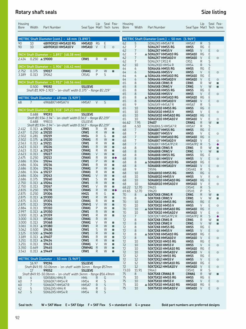
Seal tech: W = SKF Wave E = SKF Edge F = SKF Flex S = standard oil G = grease Bold part numbers are preferred designs
Rotary shaft seals Size listing
Housing Bore
Width
Part Number
Seal Type
Lip Mat'l
Seal Tech
Fea-tures
METRIC Shaft Diameter (cont.) – 48 mm (1.890")
XX HMSA RG HMSA RG E XX HMSA V HMSA V E ◎
INCH Shaft Diameter – 1.893" (48.08 mm)
. . ▲ CRW R W
INCH Shaft Diameter – 1.906" (48.41 mm)
. . CRWA P W ■
. . CRSA P S
INCH Shaft Diameter – 1.912" (48.56 mm)
. SSLEEVEShaft Ø.-.” - ‘on-shaft’ width .” - flange Ø.”
METRIC Shaft Diameter – 49 mm (1.929")
XX HMSA V HMSA V S
INCH Shaft Diameter – 1.938" (49.23 mm)
. SSLEEVEShaft Ø.-.” - ‘on-shaft’ width .” - flange Ø.”
. GSLEEVEShaft Ø.-.” - ‘on-shaft’ width .” - flange Ø.”
. . ▲ CRW R W ■
. . ▲ CRW R W ■
. . HM R G ■
. . ▲ CRWA R W ■
. . ▲ CRW R W ■
. . CRW R W ■
. . ▲ CRWA R W ■
. . CRWA V W ■
. . CRWA R W ■◆
. . CRW P W ■
. . CRW R W ■
. . CRWA P W ■
. . ▲ CRWA R W ■
. . CRWA V W ■
. . CRW S W ■
. . ▲ CRW R W ■
. . CRW V W ■
. . CRWA R W ■◆
. . HM R G ■
. . ▲ CRW R W ■
. . CRWA R W ■
. . CRWH V W ■
. . CRWA P W ■
. . ▲ CRW R W ■
. . ▲ CRW R W ■
. . CRWA R W. . CRWA V W ■
. . ▲ CRW R W ■
. . CRW S W ■
. . ▲ CRW R W ■
. . ▲ CRW R W ■
. . ▲ CRW R W ■
. . CRWA V W ■
. . CRWHA R W ■
. . ▲ CRW R W ■
METRIC Shaft Diameter – 50 mm (1.969")
. SSLEEVEShaft Ø.-.mm - 'on-shaft' width mm - flange Ømm
SSLEEVEShaft Ø.-.mm - 'on-shaft' width mm - flange Ø.mm
XX HM R HM R G XX HMS R HMS R S XX HMSA R HMSA R S XX HM R HM R G XX HMS R HMS R S
Housing Bore
Width
Part Number
Seal Type
Lip Mat'l
Seal Tech
Fea-tures
METRIC Shaft Diameter (cont.) – 50 mm (1.969")
XX HMSA R HMSA R S XX HMS RG HMS RG E XX HMS V HMS V E ◎
▲ XX HMSA RG HMSA RG E XX HMSA V HMSA V E ◎
XX CRS R CRS R S XX HMS R HMS R S XX HMS RG HMS RG E XX HMS V HMS V E ◎
▲ XX HMSA RG HMSA RG E XX HMSA V HMSA V E ◎
XX CRW R CRW R W ■
XX CRW V CRW V W ■
XX HMS RG HMS RG E XX HMS V HMS V E ◎
▲ XX HMSA RG HMSA RG E XX HMSA V HMSA V E ◎
XX HMSA R HMSA R S XX HMS RG HMS RG E XX HMS V HMS V E ◎
XX HMSA RG HMSA RG E XX HMSA V HMSA V E ◎
. . CRWA R W ■
. XX. HMSA R HMSA R S XX HMS RG HMS RG E XX HMS V HMS V E ◎
XX HMSA RG HMSA RG E XX HMSA V HMSA V E ◎
XX HMSAP R HMSAP R S ◆
XX CRW R CRW R W ■
XX CRW V CRW V W ■
XX HMS RG HMS RG E XX HMS V HMS V E ◎
▲ XX HMSA RG HMSA RG E XX HMSA V HMSA V E ◎
CRSHA R S XX HMS RG HMS RG E XX HMS V HMS V E ◎
XX HMSA RG HMSA RG E XX HMSA V HMSA V E ◎
. . CRSH R S. . CRSH P S ▲ XX CRW R CRW R W ■
XX CRW V CRW V W ■
XX HMS RG HMS RG E XX HMS V HMS V E ◎
▲ XX HMSA RG HMSA RG E XX HMSA V HMSA V E ◎
XX HMSAP R HMSAP R S ◆
XX CRW R CRW R W ■
XX CRW V CRW V W ■
XX HMS RG HMS RG E XX HMS V HMS V E ◎
▲ XX HMSA RG HMSA RG E XX HMSA V HMSA V E ◎
XX HMS RG HMS RG E XX HMS V HMS V E ◎
XX HMSA RG HMSA RG E XX HMSA V HMSA V E ◎
XX HMS RG HMS RG E XX HMS V HMS V E ◎
XX HMSA RG HMSA RG E XX HMSA V HMSA V E ◎
. . CRSH R S XX CRWA R CRWA R W ■
XX HMS RG HMS RG E XX HMS V HMS V E ◎
▲ XX HMSA RG HMSA RG E XX HMSA V HMSA V E ◎

Rotary shaft seals Size listing
Key features: ▲ WasteWatcher ■ Bore-Tite ◤ SS Case ◎ SS Spring ◆ Pressure seal up to 50 psi ◇ Cover plate required
HousingBore Width
Part Number Seal Type
Lip Mat'l
Seal Tech
Fea-tures
INCH Shaft Diameter – 1.969" (50 mm)
. . HD R G
METRIC Shaft Diameter – 50 mm (1.969")
XX CRW R CRW R W ■
XX CRW V CRW V W ■
XX HMS RG HMS RG E XX HMS V HMS V E ◎
▲ XX HMSA RG HMSA RG E XX HMSA V HMSA V E ◎
XX HMS RG HMS RG E XX HMS V HMS V E ◎
XX HMSA RG HMSA RG E XX HMSA V HMSA V E ◎
XX CRWA R CRWA R W ■
XX CRW R CRW R W ■
XX HMS RG HMS RG E XX HMS V HMS V E ◎
▲ XX HMSA RG HMSA RG E XX HMSA V HMSA V E ◎
XX CRW R CRW R W ■
XX CRW V CRW V W ■
XX HMS RG HMS RG E XX HMS V HMS V E ◎
▲ XX HMSA RG HMSA RG E XX HMSA V HMSA V E ◎
XX HMS RG HMS RG E XX HMS V HMS V E ◎
XX HMSA RG HMSA RG E XX HMSA V HMSA V E ◎
XX HMS RG HMS RG E XX HMS V HMS V E ◎
XX HMSA RG HMSA RG E XX HMSA V HMSA V E ◎
XX HMS RG HMS RG E XX HMS V HMS V E ◎
XX HMSA RG HMSA RG E XX HMSA V HMSA V E ◎
INCH Shaft Diameter – 1.980" (50.29 mm)
. SSLEEVEShaft Ø.-." - 'on-shaft' width ." - flange Ø."
INCH Shaft Diameter – 2.000" (50.80 mm)
. SSLEEVEShaft Ø.-.” - ‘on-shaft’ width .” - flange Ø.”
. GSLEEVEShaft Ø.-.” - ‘on-shaft’ width .” - flange Ø.”
. SSLEEVEShaft Ø.-.” - ‘on-shaft’ width .” - flange Ø.”
. GSLEEVEShaft Ø.-.” - ‘on-shaft’ width .” - flange Ø.”
. . HM R G ■
. . HM R G. . HM R G. . HM R G ■
. . CRW P W ■
. . HM R G ■
. . HM R G ■
. . HM R G ■
. . HM V G ■
. . CRW R W ■
. . ▲ CRWA R W ■
. . CRWA V W ■
. . CRWA V W ■◎
. . HM R G ■
. . HM R G ■
. . HM R G ■
. . ▲ CRW R W ■
. . CRW R W ■
Housing Bore
Width
Part Number
Seal Type
Lip Mat'l
Seal Tech
Fea-tures
INCH Shaft Diameter (cont.) – 2.000" (50.80 mm)
. . ▲ CRWA R W ■
. . HM R G. . CRW S W ■
. . HM R G ■
. . CRW R W ■
. . CRW V W ■
. . CRW V W ■◤◎
. . ▲ CRWA R W ■
. . CRWA V W ■
. . HM R G ■
. . ▲ CRWH R W ■
. . C R W ■
. . HM R G ■
. . ▲ CRW R W ■
. . CRW V W ■
. . CRWA R W ■
. . CRWHA R W ■
. . CRWH R W ■◤◎
. . CRWA P W ■
. . ▲ CRWA R W ■
. . HM R G ■
. . HM R G ■
. . HM R G ■
. . HM R G. . CRWH R W ■
. . CRWH V W ■
. . ▲ CRWHA R W ■
. . CRWHA V W ■
. . HM R G ■
. . CRW R W ■
. . ▲ CRWA R W ■
. . CRWA V W ■
. . CRWH R W ■
. . CRWH V W ■
. . CRWHA R W ■
. . HM R G ■
. . ▲ CRW R W ■
. . CRWH R W ■
. . CRWHA R W ■
. . ▲ CRW R W ■
. . HM R G. . ▲ CRW R W ■
. . ▲ CRWH R W ■
. . CRWHA R W ■
. . ▲ CRWH R W ■
. . CRW V W ■
. . CRWH R W ■
. . CRWH V W. . ▲ CRWHA R W ■
. . ▲ CRWH R W ■
. . HM R G. . ▲ CRWH R W ■
. . ▲ CRWH R W ■
METRIC Shaft Diameter – 51 mm (2.008")
XX CRWA R CRWA R W ■
. HMS P S
METRIC Shaft Diameter – 52 mm (2.047")
. SSLEEVEShaft Ø.-.mm - 'on-shaft' width .mm - flange Ø.mm
XX HMSA R HMSA R S XX HMS RG HMS RG E XX HMS V HMS V E ◎
XX HMSA RG HMSA RG E XX HMSA V HMSA V E ◎
XX HMSA P HMSA P S CRW R W ■
XX HMS RG HMS RG E

Seal tech: W = SKF Wave E = SKF Edge F = SKF Flex S = standard oil G = grease Bold part numbers are preferred designs
Rotary shaft seals Size listing
HousingBore Width
Part Number Seal Type
Lip Mat'l
Seal Tech
Fea-tures
METRIC Shaft Diameter (cont.) – 52 mm (2.047")
XX HMS V HMS V E ◎
XX HMSA RG HMSA RG E XX HMSA V HMSA V E ◎
XX HMSA R HMSA R S XX HMS R HMS R S XX CRW R CRW R W ■
XX CRW V CRW V W ■
XX HMS RG HMS RG E XX HMS V HMS V E ◎
▲ XX HMSA RG HMSA RG E XX HMSA V HMSA V E ◎
XX HMS R HMS R S XX CRW R CRW R W ■
XX CRW R CRW R W ■
XX CRW V CRW V W ■
XX CRWA V CRWA V W ■
XX HMS RG HMS RG E XX HMS V HMS V E ◎
▲ XX HMSA RG HMSA RG E XX HMSA V HMSA V E ◎
XX HMS RG HMS RG E XX HMS V HMS V E ◎
XX HMSA RG HMSA RG E XX HMSA V HMSA V E ◎
XX HMS R HMS R S XX HMS RG HMS RG E XX HMS V HMS V E ◎
▲ XX HMSA RG HMSA RG E XX HMSA V HMSA V E ◎
▲ XX CRW R CRW R W ■
XX HMS RG HMS RG E XX HMS V HMS V E ◎
▲ XX HMSA RG HMSA RG E XX HMSA V HMSA V E ◎
XX HMS RG HMS RG E XX HMS V HMS V E ◎
XX HMSA RG HMSA RG E XX HMSA V HMSA V E ◎
INCH Shaft Diameter – 2.063" (52.40 mm)
. SSLEEVEShaft Ø.-." - 'on-shaft' width ." - flange Ø."
. . CRW V W ■
. . HMS R S. . ▲ CRWH R W. . ▲ CRWH R W ■
. . CRSA R S ■
. . ▲ CRWH R W ■
. . ▲ CRWH R W ■
. . HM R G ■
. . ▲ CRW R W ■
. . CRWA V W ■
. . ▲ CRWH R W ■
. . ▲ CRW R W ■
. . HM R G ■
. . ▲ CRW R W ■
. . ▲ CRWH R W ■
. . CRWHA R W ■
METRIC Shaft Diameter – 53 mm (2.087")
XX CRW V CRW V W XX HMS R HMS R S. HMSA R S
INCH Shaft Diameter – 2.090" (53.09 mm)
. . HMS R S
INCH Shaft Diameter – 2.094" (53.19 mm)
. . HM R G ■
Housing Bore
Width
Part Number
Seal Type
Lip Mat'l
Seal Tech
Fea-tures
INCH Shaft Diameter (cont.) – 2.094" (53.19 mm)
. . HM R G ■
. . HM R G ■
INCH Shaft Diameter – 2.125" (53.98 mm)
. SSLEEVEShaft Ø.-." - 'on-shaft' width ." - flange Ø."
. SSLEEVEShaft Ø.-.” - ‘on-shaft’ width .” - flange Ø.”
. GSLEEVEShaft Ø.-.” - ‘on-shaft’ width .” - flange Ø.”
. . HM R G ■
. . CRW V W ■
. . ▲ CRWA R W ■
. . ▲ CRW R W ■
. . HM R G ■
. . CRW S W ■
. . CRW R W ■
. . CRW V W ■
. . ▲ CRWA R W ■
. . CRWHA R W ■
. . CRWHA V W. . HM R G ■
. . ▲ CRWH R W ■
. . CRWHA R W ■
. . HM R G ■
. . CRWHA V W ■
. . CRW V W. . CRW R W ■
. . ▲ CRWA R W ■
. . CRWH R W ■
. . CRWH V W ■
. . CRWHA R W ■
. . HM R G ■
. . CRWH V W ■
. . CRW R W ■
. . ▲ CRWA R W ■
. . CRWHA R W ■
. . ▲ CRWH R W ■
. . CRWHA P W ■
. . ▲ CRWH R W ■
. . ▲ CRWH R W ■
. . ▲ CRWA R W ■
. . CRWH R W ■
. . CRSA P S
METRIC Shaft Diameter – 54 mm (2.126")
XX CRW R CRW R W ■
XX CRW V CRW V W ■
XX HMSA P HMSA P S XX HMSA R HMSA R S . XX CRW R CRW R W ■
XX CRSH R CRSH R S . HM R G ■
. CRWA R W ■
. CRWA V W ■
. CRWHA S W ■
XX HMS R HMS R S . CRWH R W ■
INCH Shaft Diameter – 2.145" (54.48 mm)
. . CRSH R S
METRIC Shaft Diameter – 55 mm (2.165")
SSLEEVEShaft Ø.-.mm - ‘on-shaft’ width .mm - flange Ømm
GSLEEVEShaft Ø.-.mm - 'on-shaft' width .mm - flange Ømm
XX HMS RG HMS RG E XX HMS V HMS V E ◎
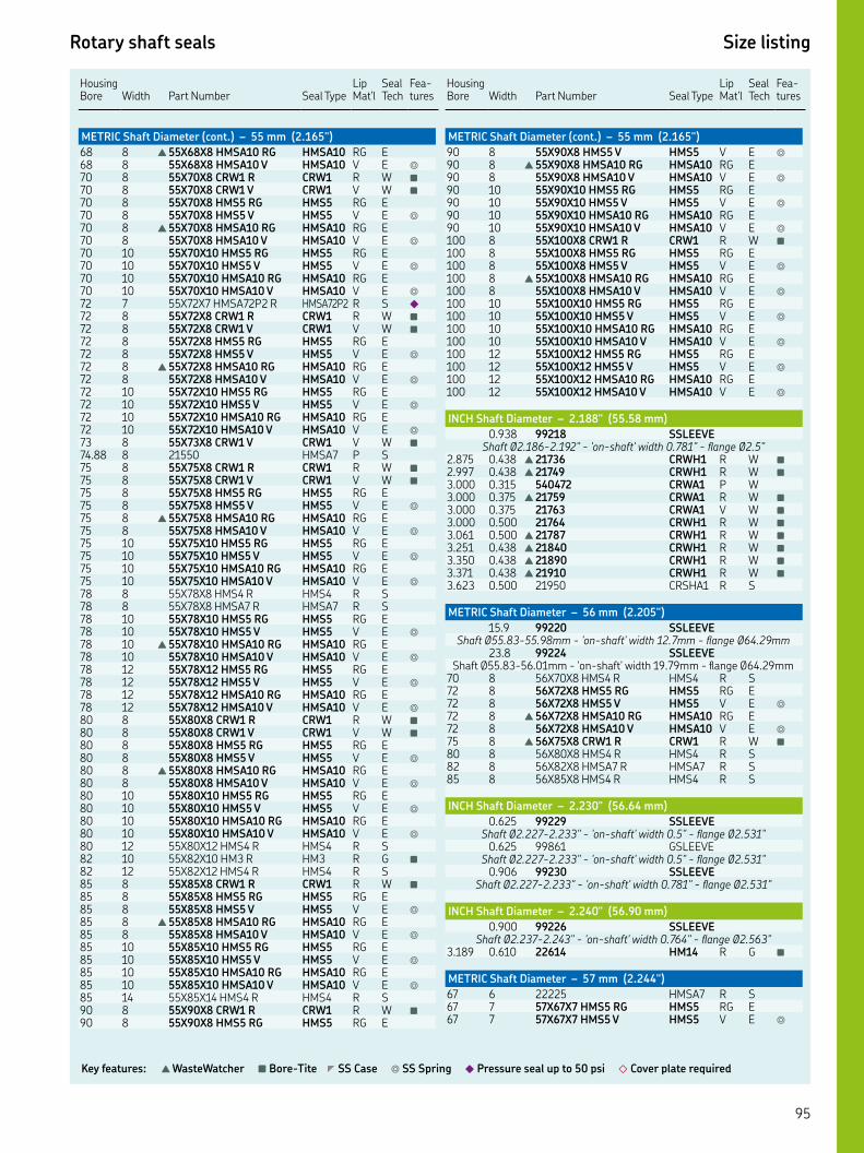
Rotary shaft seals Size listing
Key features: ▲ WasteWatcher ■ Bore-Tite ◤ SS Case ◎ SS Spring ◆ Pressure seal up to 50 psi ◇ Cover plate required
HousingBore Width
Part Number Seal Type
Lip Mat'l
Seal Tech
Fea-tures
METRIC Shaft Diameter (cont.) – 55 mm (2.165")
▲ XX HMSA RG HMSA RG E XX HMSA V HMSA V E ◎
XX CRW R CRW R W ■
XX CRW V CRW V W ■
XX HMS RG HMS RG E XX HMS V HMS V E ◎
▲ XX HMSA RG HMSA RG E XX HMSA V HMSA V E ◎
XX HMS RG HMS RG E XX HMS V HMS V E ◎
XX HMSA RG HMSA RG E XX HMSA V HMSA V E ◎
XX HMSAP R HMSAP R S ◆
XX CRW R CRW R W ■
XX CRW V CRW V W ■
XX HMS RG HMS RG E XX HMS V HMS V E ◎
▲ XX HMSA RG HMSA RG E XX HMSA V HMSA V E ◎
XX HMS RG HMS RG E XX HMS V HMS V E ◎
XX HMSA RG HMSA RG E XX HMSA V HMSA V E ◎
XX CRW V CRW V W ■
. HMSA P S XX CRW R CRW R W ■
XX CRW V CRW V W ■
XX HMS RG HMS RG E XX HMS V HMS V E ◎
▲ XX HMSA RG HMSA RG E XX HMSA V HMSA V E ◎
XX HMS RG HMS RG E XX HMS V HMS V E ◎
XX HMSA RG HMSA RG E XX HMSA V HMSA V E ◎
XX HMS R HMS R S XX HMSA R HMSA R S XX HMS RG HMS RG E XX HMS V HMS V E ◎
▲ XX HMSA RG HMSA RG E XX HMSA V HMSA V E ◎
XX HMS RG HMS RG E XX HMS V HMS V E ◎
XX HMSA RG HMSA RG E XX HMSA V HMSA V E ◎
XX CRW R CRW R W ■
XX CRW V CRW V W ■
XX HMS RG HMS RG E XX HMS V HMS V E ◎
▲ XX HMSA RG HMSA RG E XX HMSA V HMSA V E ◎
XX HMS RG HMS RG E XX HMS V HMS V E ◎
XX HMSA RG HMSA RG E XX HMSA V HMSA V E ◎
XX HMS R HMS R S XX HM R HM R G ■
XX HMS R HMS R S XX CRW R CRW R W ■
XX HMS RG HMS RG E XX HMS V HMS V E ◎
▲ XX HMSA RG HMSA RG E XX HMSA V HMSA V E ◎
XX HMS RG HMS RG E XX HMS V HMS V E ◎
XX HMSA RG HMSA RG E XX HMSA V HMSA V E ◎
XX HMS R HMS R S XX CRW R CRW R W ■
XX HMS RG HMS RG E
Housing Bore
Width
Part Number
Seal Type
Lip Mat'l
Seal Tech
Fea-tures
METRIC Shaft Diameter (cont.) – 55 mm (2.165")
XX HMS V HMS V E ◎
▲ XX HMSA RG HMSA RG E XX HMSA V HMSA V E ◎
XX HMS RG HMS RG E XX HMS V HMS V E ◎
XX HMSA RG HMSA RG E XX HMSA V HMSA V E ◎
XX CRW R CRW R W ■
XX HMS RG HMS RG E XX HMS V HMS V E ◎
▲ XX HMSA RG HMSA RG E XX HMSA V HMSA V E ◎
XX HMS RG HMS RG E XX HMS V HMS V E ◎
XX HMSA RG HMSA RG E XX HMSA V HMSA V E ◎
XX HMS RG HMS RG E XX HMS V HMS V E ◎
XX HMSA RG HMSA RG E XX HMSA V HMSA V E ◎
INCH Shaft Diameter – 2.188" (55.58 mm)
. SSLEEVEShaft Ø.-." - 'on-shaft' width ." - flange Ø."
. . ▲ CRWH R W ■
. . ▲ CRWH R W ■
. . CRWA P W. . ▲ CRWA R W ■
. . CRWA V W ■
. . CRWH R W ■
. . ▲ CRWH R W ■
. . ▲ CRWH R W ■
. . ▲ CRWH R W ■
. . ▲ CRWH R W ■
. . CRSHA R S
METRIC Shaft Diameter – 56 mm (2.205")
. SSLEEVEShaft Ø.-.mm - 'on-shaft' width .mm - flange Ø.mm
. SSLEEVEShaft Ø.-.mm - 'on-shaft' width .mm - flange Ø.mm
XX HMS R HMS R S XX HMS RG HMS RG E XX HMS V HMS V E ◎
▲ XX HMSA RG HMSA RG E XX HMSA V HMSA V E ◎
▲ XX CRW R CRW R W ■
XX HMS R HMS R S XX HMSA R HMSA R S XX HMS R HMS R S
INCH Shaft Diameter – 2.230" (56.64 mm)
. SSLEEVEShaft Ø.-." - 'on-shaft' width ." - flange Ø."
. GSLEEVEShaft Ø.-." - 'on-shaft' width ." - flange Ø."
. SSLEEVEShaft Ø.-." - 'on-shaft' width ." - flange Ø."
INCH Shaft Diameter – 2.240" (56.90 mm)
. SSLEEVEShaft Ø.-." - 'on-shaft' width ." - flange Ø."
. . HM R G ■
METRIC Shaft Diameter – 57 mm (2.244")
HMSA R S XX HMS RG HMS RG E XX HMS V HMS V E ◎

Seal tech: W = SKF Wave E = SKF Edge F = SKF Flex S = standard oil G = grease Bold part numbers are preferred designs
Rotary shaft seals Size listing
HousingBore Width
Part Number Seal Type
Lip Mat'l
Seal Tech
Fea-tures
METRIC Shaft Diameter (cont.) – 57 mm (2.244")
XX HMSA RG HMSA RG E XX HMSA V HMSA V E ◎
XX HMSA R HMSA R S
INCH Shaft Diameter – 2.250" (57.15 mm)
. SSLEEVEShaft Ø.-." - 'on-shaft' width ." - flange Ø."
. GSLEEVEShaft Ø.-." - 'on-shaft' width ." - flange Ø."
. SSLEEVEShaft Ø.-." - 'on-shaft' width ." - flange Ø."
. GSLEEVEShaft Ø.-." - 'on-shaft' width ." - flange Ø."
. . HM R G ■
. . ▲ CRWA R W ■
. . CRWA R W ■
. . ▲ CRWH R W ■
. . ▲ CRWHA R W ■
. . HM R G ■
. . CRW R W ■
. . CRW V W ■
. . ▲ CRWA R W ■
. . CRWA V W ■
. . CRWH R W ■
. . CRWH V W ■
. . CRWHA R W ■
. . HM R G. . ▲ CRW R W ■
. . CRWH R W ■
. . CRWHA R W ■
. . CRWHA S W ■
. . ▲ CRWA R W ■
. . CRWA V W ■
. . CRWH R W. . HM R G. . CRWA P W ■
. . ▲ CRW R W ■
. . HM R G. . ▲ CRW R W ■
. . ▲ CRWA R W ■
. . CRWH R W ■
. . CRWH V W ■
. . CRWHA R W ■
. . HM R G ■
. . CRW P W ■
. . ▲ CRWH R W. . CRWH V W ■
. . CRWHA R W ■
. . HM R G ■
. . CRWH R W ■
. . CRWH V W ■
. . ▲ CRWHA R W ■
. . HM R G ■
. . ▲ CRWH R W ■
. . CRWHA R W ■
. . CRWHA V W ■
. . ▲ CRWA R W ■
. . ▲ CRWHA R W ■
. . CRWH R W ■
. . ▲ CRWH R W ■
. . CRWH R W ■
. . ▲ CRWH R W ■
METRIC Shaft Diameter – 58 mm (2.283")
. SSLEEVEShaft Ø.-.mm - 'on-shaft' width mm - flange Ømm
XX CRW R CRW R W ■
XX CRW S CRW S W ■
XX HMS RG HMS RG E
Housing Bore
Width
Part Number
Seal Type
Lip Mat'l
Seal Tech
Fea-tures
METRIC Shaft Diameter (cont.) – 58 mm (2.283")
XX HMS V HMS V E ◎
▲ XX HMSA RG HMSA RG E XX HMSA V HMSA V E ◎
▲ XX CRW R CRW R W ■
XX HMSA R HMSA R S XX HMS R HMS R S XX CRW R CRW R W ■
XX CRW V CRW V W ■
XX HMS RG HMS RG E XX HMS V HMS V E ◎
▲ XX HMSA RG HMSA RG E XX HMSA V HMSA V E ◎
XX HMS RG HMS RG E XX HMS V HMS V E ◎
XX HMSA RG HMSA RG E XX HMSA V HMSA V E ◎
XX HMS RG HMS RG E XX HMS V HMS V E ◎
XX HMSA RG HMSA RG E XX HMSA V HMSA V E ◎
. . HM R G ■
XX CRW R CRW R W ■
XX HMS R HMS R S XX CRW R CRW R W ■
XX HMSA R HMSA R S
INCH Shaft Diameter – 2.297" (58.34 mm)
. . HM R G
INCH Shaft Diameter – 2.313" (58.75 mm)
. SSLEEVEShaft Ø.-.” - ‘on-shaft’ width .” - flange Ø.”
. . ▲ CRW R W ■
. . HM R G ■
. . CRWH V W ■
. . ▲ CRW R W ■
. . HM R G. . ▲ CRW R W ■
. . CRWA V W ■
. . ▲ CRWH R W ■
. . CRWHA V W. . HM R G ■
. . CRWH R W ■
. . ▲ CRW R W ■
. . ▲ CRWHA R W ■
. . HM R G ■
. . ▲ CRW R W. . CRW R W ■
METRIC Shaft Diameter – 59 mm (2.323")
HMSA R S
INCH Shaft Diameter – 2.328" (59.13 mm)
. . CRW P W ■
INCH Shaft Diameter – 2.330" (59.18 mm)
. SSLEEVEShaft Ø.-." - 'on-shaft' width ." - flange Ø."
INCH Shaft Diameter – 2.359" (59.92 mm)
. . PLUS XL H W
METRIC Shaft Diameter – 60 mm (2.362")
. SSLEEVEShaft Ø.-.mm - ‘on-shaft’ width .mm - flange Ø.mm
SSLEEVEShaft Ø.-.mm - ‘on-shaft’ width .mm - flange Ø.mm

Rotary shaft seals Size listing
Key features: ▲ WasteWatcher ■ Bore-Tite ◤ SS Case ◎ SS Spring ◆ Pressure seal up to 50 psi ◇ Cover plate required
HousingBore Width
Part Number Seal Type
Lip Mat'l
Seal Tech
Fea-tures
METRIC Shaft Diameter (cont.) – 60 mm (2.362")
GSLEEVEShaft Ø.-.mm - ‘on-shaft’ width mm - flange Ø.mm
XX CRS R CRS R S XX HMS RG HMS RG E XX HMS V HMS V E ◎
▲ XX HMSA RG HMSA RG E XX HMSA V HMSA V E ◎
HMSA V S XX CRW R CRW R W ■
XX CRW V CRW V W ■
XX HMS RG HMS RG E XX HMS V HMS V E ◎
▲ XX HMSA RG HMSA RG E XX HMSA V HMSA V E ◎
XX CRS R CRS R S ■
XX HMSA R HMSA R S XX HMS RG HMS RG E XX HMS V HMS V E ◎
XX HMSA RG HMSA RG E XX HMSA V HMSA V E ◎
XX CRW R CRW R W ■
XX CRW V CRW V W ■
XX HMS RG HMS RG E XX HMS V HMS V E ◎
▲ XX HMSA RG HMSA RG E XX HMSA V HMSA V E ◎
XX HMS RG HMS RG E XX HMS V HMS V E ◎
XX HMSA RG HMSA RG E XX HMSA V HMSA V E ◎
XX CRSHA R CRSHA R S XX HMS R HMS R S XX HMS R HMS R S ▲ XX CRWA R CRWA R W ■
XX HMSA R HMSA R S XX HMS RG HMS RG E XX HMS V HMS V E ◎
▲ XX HMSA RG HMSA RG E XX HMSA V HMSA V E ◎
XX CRW R CRW R W ■
XX CRW V CRW V W ■
XX HMS RG HMS RG E XX HMS V HMS V E ◎
▲ XX HMSA RG HMSA RG E XX HMSA V HMSA V E ◎
XX HMS RG HMS RG E XX HMS V HMS V E ◎
XX HMSA RG HMSA RG E XX HMSA V HMSA V E ◎
XX CRW R CRW R W ■
XX HMS RG HMS RG E XX HMS V HMS V E ◎
▲ XX HMSA RG HMSA RG E XX HMSA V HMSA V E ◎
XX HMS RG HMS RG E XX HMS V HMS V E ◎
XX HMSA RG HMSA RG E XX HMSA V HMSA V E ◎
XX HMS RG HMS RG E XX HMS V HMS V E ◎
XX HMSA RG HMSA RG E XX HMSA V HMSA V E ◎
XX CRSH R CRSH R S XX HMS R HMS R S XX HMSA R HMSA R S XX HMS RG HMS RG E XX HMS V HMS V E ◎
▲ XX HMSA RG HMSA RG E XX HMSA V HMSA V E ◎
XX HMS RG HMS RG E
Housing Bore
Width
Part Number
Seal Type
Lip Mat'l
Seal Tech
Fea-tures
XX HMS V HMS V E ◎
XX HMSA RG HMSA RG E XX HMSA V HMSA V E ◎
XX CRW R CRW R W ■
XX CRW R CRW R W ■
XX HMS RG HMS RG E XX HMS V HMS V E ◎
▲ XX HMSA RG HMSA RG E XX HMSA V HMSA V E ◎
XX HMS RG HMS RG E XX HMS V HMS V E ◎
XX HMSA RG HMSA RG E XX HMSA V HMSA V E ◎
XX HMS RG HMS RG E XX HMS V HMS V E ◎
XX HMSA RG HMSA RG E XX HMSA V HMSA V E ◎
INCH Shaft Diameter – 2.375" (60.33 mm)
. SSLEEVEShaft Ø.-.” - ‘on-shaft’ width .” - flange Ø.”
. SSLEEVEShaft Ø.-.” - ‘on-shaft’ width .” - flange Ø.”
. SSLEEVEShaft Ø.-.” - ‘on-shaft’ width .” - flange Ø.”
. GSLEEVEShaft Ø.-.” - ‘on-shaft’ width .” - flange Ø.”
. . ▲ CRWA R W. . HM R G ■
. . ▲ CRWH R W ■
. . HM R G. . CRW V W ■
. . CRWH P W ■
. . ▲ CRWH R W ■
. . CRWH V W ■◎
. . ▲ CRW R W ■
. . CRWH R W ■
. . CRWHA R W ■
. . CRWHA V W ■
. . ▲ CRWH R W ■
. . ▲ CRWHA R W ■
. . CRWHA V W ■
. . CRW P W ■
. . HM R G ■
. . CRW P W ■
. . ▲ CRW R W ■
. . CRW S W ■
. . CRWA R W ■
. . CRWH R W ■
. . CRWHA R W ■
. . ▲ CRWH R W ■
. . CRWH V W ■
. . ▲ CRWH R W ■
. . CRWHA R W. . CRWA P W ■
. . ▲ CRWH R W ■
. . CRWH V W ■
. . CRWHA R W ■
. . HM R G ■
. . ▲ CRWH R W ■
. . CRWHA V W ■
. . CRW R W ■
. . ▲ CRWH R W ■
. . CRWHA P W ■
. . CRWHA V W ■◎
. . ▲ CRWH R W ■
INCH Shaft Diameter – 2.438" (61.93 mm)
. SSLEEVEShaft Ø.-.” - ‘on-shaft’ width .” - flange Ø.”
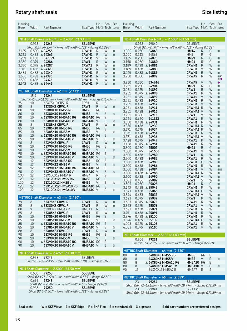
Seal tech: W = SKF Wave E = SKF Edge F = SKF Flex S = standard oil G = grease Bold part numbers are preferred designs
Rotary shaft seals Size listing
HousingBore Width
Part Number Seal Type
Lip Mat'l
Seal Tech
Fea-tures
INCH Shaft Diameter (cont.) – 2.438" (61.93 mm)
. SSLEEVEShaft Ø.-.” - ‘on-shaft’ width .” - flange Ø.”
. . ▲ CRWH R W ■
. . ▲ CRWH R W ■
. . CRWH V W. . CRW R W ■
. . ▲ CRWA R W ■
. . ▲ CRWH R W ■
. . ▲ CRWH R W ■
. . ▲ CRWH R W ■
. . CRWH V W ■
. . ▲ CRWH R W ■
METRIC Shaft Diameter – 62 mm (2.441")
. SSLEEVEShaft Ø.-.mm - 'on-shaft' width .mm - flange Ø.mm
XX CRS R CRS R S XX CRW R CRW R W ■
XX HMS RG HMS RG E XX HMS V HMS V E ◎
▲ XX HMSA RG HMSA RG E XX HMSA V HMSA V E ◎
XX CRW R CRW R W ■
XX HMS RG HMS RG E XX HMS V HMS V E ◎
▲ XX HMSA RG HMSA RG E XX HMSA V HMSA V E ◎
XX CRW R CRW R W ■
XX HMS RG HMS RG E XX HMS V HMS V E ◎
▲ XX HMSA RG HMSA RG E XX HMSA V HMSA V E ◎
XX HMS RG HMS RG E XX HMS V HMS V E ◎
XX HMSA RG HMSA RG E XX HMSA V HMSA V E ◎
XX HMS R HMS R S XX HMS RG HMS RG E XX HMS V HMS V E ◎
XX HMSA RG HMSA RG E XX HMSA V HMSA V E ◎
METRIC Shaft Diameter – 63 mm (2.480")
XX CRW R CRW R W ■
▲ XX CRW R CRW R W ■
XX HMSA R HMSA R S XX CRW R CRW R W ■
XX HMS RG HMS RG E XX HMS V HMS V E ◎
▲ XX HMSA RG HMSA RG E XX HMSA V HMSA V E ◎
XX CRW R CRW R W ■
XX HMS RG HMS RG E XX HMS V HMS V E ◎
▲ XX HMSA RG HMSA RG E XX HMSA V HMSA V E ◎
INCH Shaft Diameter – 2.492" (63.30 mm)
. SSLEEVEShaft Ø.-.” - ‘on-shaft’ width .” - flange Ø.”
INCH Shaft Diameter – 2.500" (63.50 mm)
. SSLEEVEShaft Ø.-.” - ‘on-shaft’ width .” - flange Ø.”
. SSLEEVEShaft Ø.-.” - ‘on-shaft’ width .” - flange Ø.”. SSLEEVE
Shaft Ø.-.” - ‘on-shaft’ width .” - flange Ø.”
Housing Bore
Width
Part Number
Seal Type
Lip Mat'l
Seal Tech
Fea-tures
INCH Shaft Diameter (cont.) – 2.500" (63.50 mm)
. GSLEEVEShaft Ø.-.” - ‘on-shaft’ width .” - flange Ø.”
. . HM R G ■
. . HM R G. . HM R G ■
. . HM R G ■
. . ▲ CRWH R W ■
. . CRWH V W ■
. . ▲ CRWH R W ■
. . CRWA R W ■◤ ◎◆
. . CRWA V W ◆
. . HM R G ■
. . CRW R W ■
. . ▲ CRWA R W ■
. . CRWA V W ■
. . CRWH R W ■
. . CRWH V W ■
. . CRWHA R W ■
. . CRWHA V W ■
. . CRW V W ■
. . CRWA R W ■
. . ▲ CRWH R W ■
. . CRWHA R W ■
. . CRWHA R W. . ▲ CRWH R W ■
. . CRWHA V W ■
. . CRWA P W ■
. . ▲ CRWA R W ■
. . HM R G ■
. . CRWA V W ■
. . CRW R W ■
. . CRWA R W ■
. . CRWH P W ■
. . CRWH R W ■
. . CRWH V W ■◎
. . ▲ CRWHA R W ■
. . CRWHA V W ■
. . CRW S W ■
. . HM R G ■
. . ▲ CRWH R W ■
. . CRWHA P W. . CRWHA V W ■
. . CRW R W ■
. . ▲ CRWA R W ■
. . CRWA V W ■
. . CRWH R W. . ▲ CRWH R W. . ▲ CRWH R W ■
. . CRWHA P W ■
. . ▲ CRWA R W ■
. . CRWA V W ■
INCH Shaft Diameter – 2.513" (63.83 mm)
. SSLEEVEShaft Ø.-." - 'on-shaft' width ." - flange Ø."
METRIC Shaft Diameter – 64 mm (2.520")
XX HMS RG HMS RG E XX HMS V HMS V E ◎
▲ XX HMSA RG HMSA RG E XX HMSA V HMSA V E ◎
XX HMSA R HMSA R S
METRIC Shaft Diameter – 65 mm (2.559")
SSLEEVEShaft Ø.-.mm - ‘on-shaft’ width .mm - flange Ø.mm
GSLEEVEShaft Ø.-.mm - ‘on-shaft’ width .mm - flange Ø.mm

Rotary shaft seals Size listing
Key features: ▲ WasteWatcher ■ Bore-Tite ◤ SS Case ◎ SS Spring ◆ Pressure seal up to 50 psi ◇ Cover plate required
HousingBore Width
Part Number Seal Type
Lip Mat'l
Seal Tech
Fea-tures
METRIC Shaft Diameter (cont.) – 65 mm (2.559")
XX CRW R CRW R W ■
XX CRW V CRW V W ■
XX HMS RG HMS RG E XX HMS V HMS V E ◎
▲ XX HMSA RG HMSA RG E XX HMSA V HMSA V E ◎
XX HMS R HMS R S XX HMSA P HMSA P S XX CRW R CRW R W ■
XX CRW V CRW V W ■◎
XX HMS RG HMS RG E XX HMS V HMS V E ◎
▲ XX HMSA RG HMSA RG E XX HMSA V HMSA V E ◎
XX HMS RG HMS RG E XX HMS V HMS V E ◎
▲ XX HMSA RG HMSA RG E XX HMSA V HMSA V E ◎
XX HMS RG HMS RG E XX HMS V HMS V E ◎
XX HMSA RG HMSA RG E XX HMSA V HMSA V E ◎
XX CRW R CRW R W ■
XX HMSA R HMSA R S XX HMS RG HMS RG E XX HMS V HMS V E ◎
▲ XX HMSA RG HMSA RG E XX HMSA V HMSA V E ◎
XX HMS RG HMS RG E XX HMS V HMS V E ◎
▲ XX HMSA RG HMSA RG E XX HMSA V HMSA V E ◎
▲ XX CRW R CRW R W ■
XX CRW V CRW V W ■
XX HMS RG HMS RG E XX HMS V HMS V E ◎
▲ XX HMSA RG HMSA RG E XX HMSA V HMSA V E ◎
XX HMS R HMS R S XX HMSA R HMSA R S . XX. CRWH R CRWH R W ■
XX HMS RG HMS RG E XX HMS V HMS V E ◎
▲ XX HMSA RG HMSA RG E XX HMSA V HMSA V E ◎
▲ XX CRW R CRW R W ■
XX CRW V CRW V W ■
XX HMS RG HMS RG E XX HMS V HMS V E ◎
▲ XX HMSA RG HMSA RG E XX HMSA V HMSA V E ◎
▲ XX CRW R CRW R W ■
XX HMS RG HMS RG E XX HMS V HMS V E ◎
XX HMSA RG HMSA RG E XX HMSA V HMSA V E ◎
▲ XX CRW R CRW R W ■
XX HMS RG HMS RG E XX HMS V HMS V E ◎
▲ XX HMSA RG HMSA RG E XX HMSA V HMSA V E ◎
XX HMS RG HMS RG E XX HMS V HMS V E ◎
XX HMSA RG HMSA RG E XX HMSA V HMSA V E ◎
XX HMS RG HMS RG E XX HMS V HMS V E ◎
XX HMSA RG HMSA RG E XX HMSA V HMSA V E ◎
Housing Bore
Width
Part Number
Seal Type
Lip Mat'l
Seal Tech
Fea-tures
INCH Shaft Diameter – 2.562" (65.07 mm)
. . CRW R W. . CRWHA V W
INCH Shaft Diameter – 2.563" (65.10 mm)
. SSLEEVEShaft Ø.-." - 'on-shaft' width ." - flange Ø."
. . CRWHA R W ■
. . ▲ CRWH R W ■
. . CRSHA P S. . ▲ CRWH R W ■
. . CRWA P W ■
. . CRWA V W ■
. . ▲ CRWH R W ■
. . CRWH V W ■
. . CRWHA R W ■
. . ▲ CRWHA R W. . CRWH R W ■
METRIC Shaft Diameter – 66 mm (2.598")
. SSLEEVEShaft Ø.-.mm - 'on-shaft' width .mm - flange Ø.mm
. XX. CRSHA R CRSHA R S . XX CRWHA R CRWHA R W ■
. . CRWHA P W ■
INCH Shaft Diameter – 2.607" (66.22 mm)
. . CRWH P W ■
INCH Shaft Diameter – 2.621" (66.57 mm)
. SSLEEVEShaft Ø.-." - 'on-shaft' width ." - flange Ø."
INCH Shaft Diameter – 2.625" (66.68 mm)
. SSLEEVEShaft Ø.-." - 'on-shaft' width ." - flange Ø."
. SSLEEVEShaft Ø.-." - 'on-shaft' width ." - flange Ø."
. . HM R G. . ▲ CRWH R W ■
. . CRW R W ■
. . CRW V W ■
. . CRWA R W ■
. . CRW R W. . HM R G ■
. . ▲ CRWHA R W ■
. . CRWHA V W. . ▲ CRWHA R W ■
. . CRWH R W ■
. . CRW V W ■
. . ▲ CRWA R W ■
. . CRWA P W ■
. . CRWH R W ■
. . CRWHA R W ■
. . CRWH R W ■
. . HM R G ■
. . CRW R W ■
. . CRW V W ■
. . CRWA P W ■
. . CRWA R W ■
. . ▲ CRWH R W ■
. . CRWH V W ■
. . CRWHA R W ■
. . ▲ CRWA R W ■
. . CRWH R W ■
. . CRWHA R W ■
. . CRWHA V W ■
. . ▲ CRWH R W ■
. . CRWH R W ■

Seal tech: W = SKF Wave E = SKF Edge F = SKF Flex S = standard oil G = grease Bold part numbers are preferred designs
Rotary shaft seals Size listing
HousingBore Width
Part Number Seal Type
Lip Mat'l
Seal Tech
Fea-tures
INCH Shaft Diameter (cont.) – 2.625" (66.68 mm)
. . ▲ CRWA R W ■
. . CRWH R W ■
. . ▲ CRWHA R W ■
. . ▲ CRWH R W ■
INCH Shaft Diameter – 2.628" (66.75 mm)
. SSLEEVEShaft Ø.-." - 'on-shaft' width ." - flange Ø."
. GSLEEVEShaft Ø.-." - 'on-shaft' width ." - flange Ø."
METRIC Shaft Diameter – 67 mm (2.638")
XX HMS P HMS P S
INCH Shaft Diameter – 2.648" (67.26 mm)
. . CRS R S ■
INCH Shaft Diameter – 2.667" (67.74 mm)
. . HM R G
METRIC Shaft Diameter – 68 mm (2.677")
. SSLEEVEShaft Ø.-mm - 'on-shaft' width .mm - flange Ø.mm
XX CRW R CRW R W ■
XX HMS V HMS V S XX CRW R CRW R W ■
XX CRW R CRW R W ■
XX CRW V CRW V W ■
XX HMS RG HMS RG E XX HMS V HMS V E ◎
▲ XX HMSA RG HMSA RG E XX HMSA V HMSA V E ◎
XX CRW R CRW R W ■
XX CRW V CRW V W ■
XX HMS R HMS R S XX CRW R CRW R W ■
XX HMS R HMS R S XX HMSA R HMSA R S
INCH Shaft Diameter – 2.688" (68.28 mm)
. . ▲ CRWH R W ■
. . ▲ CRWH R W ■
. . ▲ CRWH R W ■
)INCH Shaft Diameter – 2.730" (69.34 mm
. SSLEEVEShaft Ø.-." - 'on-shaft' width ." - flange Ø."
INCH Shaft Diameter – 2.743" (69.67 mm)
. SSLEEVEShaft Ø.-." - 'on-shaft' width ." - flange Ø."
INCH Shaft Diameter – 2.748" (69.80 mm)
. SSLEEVEShaft Ø.-." - 'on-shaft' width ." - flange Ø."
. GSLEEVEShaft Ø.-." - 'on-shaft' width ." - flange Ø."
INCH Shaft Diameter – 2.750" (69.85 mm)
. SSLEEVEShaft Ø.-." - 'on-shaft' width ." - flange Ø."
. . HM R G. . HM R G. . ▲ CRW R W. . HM R G ■
. . HM V G ■
. . CRW R W ■
Housing Bore
Width
Part Number
Seal Type
Lip Mat'l
Seal Tech
Fea-tures
INCH Shaft Diameter (cont.) – 2.750" (69.85 mm)
. . ▲ CRWA R W ■
. . CRWA V W ■
. . CRWH R W ■
. . ▲ CRWH R W ■
. . CRWH V W ■
. . CRWH P W ■
. . CRWHA P W ■
. . ▲ CRWH R W ■
. . CRWH V W ■
. . HM R G ■
. . CRW R W ■
. . CRWA P W ■
. . CRWA R W ■
. . CRWH R W ■
. . CRWH V W ■
. . ▲ CRWHA R W ■
. . ▲ CRWH R W ■
. . SCOT R S ■
. . CRWHA P W ■
. . CRWA R W ■
. . ▲ CRWH R W ■
. . CRWHA R W ■
. . ▲ CRWH R W ■
. . CRWA P W ■
. . CRWA V W ■
. . ▲ CRWH R W ■
. . CRWHA P W. . CRS P S ■
. . CRSA R S. . ▲ CRWH R W ■
. . CRWHA P W ■
. . ▲ CRWHA R W ■
METRIC Shaft Diameter – 70 mm (2.756")
. SSLEEVEShaft Ø.-.mm - ‘on-shaft’ width .mm - flange Ø.mm
. SSLEEVEShaft Ø.-.mm - ‘on-shaft’ width .mm - flange Ø.mm
. GSLEEVEShaft Ø.-.mm - ‘on-shaft’ width .mm - flange Ø.mm
SSLEEVEShaft Ø.-.mm - ‘on-shaft’ width .mm - flange Ø.mm
. SSLEEVEShaft Ø.-.mm - 'on-shaft' width .mm - flange Ø.mm
XX HMS R HMS R S XX HMSA R HMSA R S XX CRW R CRW R W ■
XX HMS RG HMS RG E XX HMS V HMS V E ◎
▲ XX HMSA RG HMSA RG E XX HMSA V HMSA V E ◎
▲ XX CRW R CRW R W ■
XX CRW V CRW V W ■
XX HMS R HMS R S XX HMS RG HMS RG E XX HMS V HMS V E ◎
XX HMSA RG HMSA RG E XX HMSA V HMSA V E ◎
XX HMSAP R HMSAP R S ◆
XX CRW R CRW R W ■
XX CRW H CRW H W ■
XX CRW V CRW V W ■
XX CRWHA P CRWHA P W ■
XX HMS RG HMS RG E XX HMS V HMS V E ◎
▲ XX HMSA RG HMSA RG E XX HMSA V HMSA V E ◎
XX HMS RG HMS RG E XX HMS V HMS V E ◎
XX HMSA RG HMSA RG E
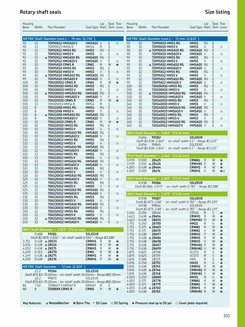
Rotary shaft seals Size listing
Key features: ▲ WasteWatcher ■ Bore-Tite ◤ SS Case ◎ SS Spring ◆ Pressure seal up to 50 psi ◇ Cover plate required
HousingBore Width
Part Number Seal Type
Lip Mat'l
Seal Tech
Fea-tures
METRIC Shaft Diameter (cont.) – 70 mm (2.756" )
XX HMSA V HMSA V E ◎
XX HMS R HMS R S XX HMS RG HMS RG E XX HMS V HMS V E ◎
▲ XX HMSA RG HMSA RG E XX HMSA V HMSA V E ◎
XX CRW R CRW R W ■
XX HMS RG HMS RG E XX HMS V HMS V E ◎
▲ XX HMSA RG HMSA RG E XX HMSA V HMSA V E ◎
XX CRW R CRW R W ■
XX HMS RG HMS RG E XX HMS V HMS V E ◎
▲ XX HMSA RG HMSA RG E XX HMSA V HMSA V E ◎
XX CRW R CRW R W ■
XX HMS R HMS R S XX HMS RG HMS RG E XX HMS V HMS V E ◎
▲ XX HMSA RG HMSA RG E XX HMSA V HMSA V E ◎
XX CRW R CRW R W ■
XX HMS RG HMS RG E XX HMS V HMS V E ◎
XX HMSA RG HMSA RG E XX HMSA V HMSA V E ◎
XX HMS RG HMS RG E XX HMS V HMS V E ◎
XX HMSA RG HMSA RG E XX HMSA V HMSA V E ◎
XX HMS RG HMS RG E XX HMS V HMS V E ◎
XX HMSA RG HMSA RG E XX HMSA V HMSA V E ◎
XX HMS RG HMS RG E XX HMS V HMS V E ◎
XX HMSA RG HMSA RG E XX HMSA V HMSA V E ◎
XX HMS RG HMS RG E XX HMS V HMS V E ◎
XX HMSA RG HMSA RG E XX HMSA V HMSA V E ◎
XX HMS RG HMS RG E XX HMS V HMS V E ◎
XX HMSA RG HMSA RG E XX HMSA V HMSA V E ◎
XX HMS RG HMS RG E XX HMS V HMS V E ◎
▲ XX HMSA RG HMSA RG E XX HMSA V HMSA V E ◎
INCH Shaft Diameter – 2.813" (71.45 mm)
. SSLEEVEShaft Ø.-." - 'on-shaft' width ." - flange Ø."
. . ▲ CRWH R W ■
. . ▲ CRWH R W ■
. . ▲ CRWH R W ■
. . CRW R W ■
. . ▲ CRWH R W ■
. . CRWH P W ■
METRIC Shaft Diameter – 72 mm (2.835" )
. SSLEEVEShaft Ø.-.mm - ‘on-shaft’ width .mm - flange Ø.mm
. GSLEEVEShaft Ø.-.mm - ‘on-shaft’ width .mm - flange Ø.mm
. XX. HMSA R HMSA R S XX CRW R CRW R W ■
Housing Bore
Width
Part Number
Seal Type
Lip Mat'l
Seal Tech
Fea-tures
METRIC Shaft Diameter (cont.) – 72 mm (2.835" )
XX HMS RG HMS RG E XX HMS V HMS V E ◎
▲ XX HMSA RG HMSA RG E XX HMSA V HMSA V E ◎
XX HMS RG HMS RG E XX HMS V HMS V E ◎
▲ XX HMSA RG HMSA RG E XX HMSA V HMSA V E ◎
XX HMS RG HMS RG E XX HMS V HMS V E ◎
XX HMSA RG HMSA RG E XX HMSA V HMSA V E ◎
XX HMS RG HMS RG E XX HMS V HMS V E ◎
▲ XX HMSA RG HMSA RG E XX HMSA V HMSA V E ◎
XX HMS RG HMS RG E XX HMS V HMS V E ◎
XX HMSA RG HMSA RG E XX HMSA V HMSA V E ◎
XX HMS RG HMS RG E XX HMS V HMS V E ◎
XX HMSA RG HMSA RG E XX HMSA V HMSA V E ◎
INCH Shaft Diameter – 2.841" (72.16 mm)
. SSLEEVEShaft Ø.-." - 'on-shaft' width ." - flange Ø."
. GSLEEVEShaft Ø.-." - 'on-shaft' width ." - flange Ø."
INCH Shaft Diameter – 2.844" (72.24 mm)
. . CRWA R W ■
. . ▲ CRWHA R W ■
. . ▲ CRWH R W ■
. . CRWH V W ■◎
INCH Shaft Diameter – 2.869" (72.87 mm)
. SSLEEVEShaft Ø.-." - 'on-shaft' width ." - flange Ø."
INCH Shaft Diameter – 2.875" (73.03 mm)
. SSLEEVEShaft Ø.-.” - ‘on-shaft’ width .” - flange Ø.”
. GSLEEVEShaft Ø.-.” - ‘on-shaft’ width .” - flange Ø.”
. . CRSA R S ■
. . ▲ CRWH R W ■
. . CRWHA R W ■
. . HM R G ■
. . ▲ CRWA R W ■
. . CRWA V W ■
. . CRWH P W ■
. . ▲ CRWH R W ■
. . CRWH V W ■
. . CRWHA R W ■
. . CRWHA V W ■
. . SCOT R S ■
. . SCOT R S ■
. . HM R G ■
. . HM R G ■
. . CRWH R W ■
. . ▲ CRWHA R W ■
. . CRWHA V W ■
. . HM R G ■
. . CRWA R W ■
. . CRWA V W ■
. . ▲ CRWH R W ■
. . CRWHA R W ■
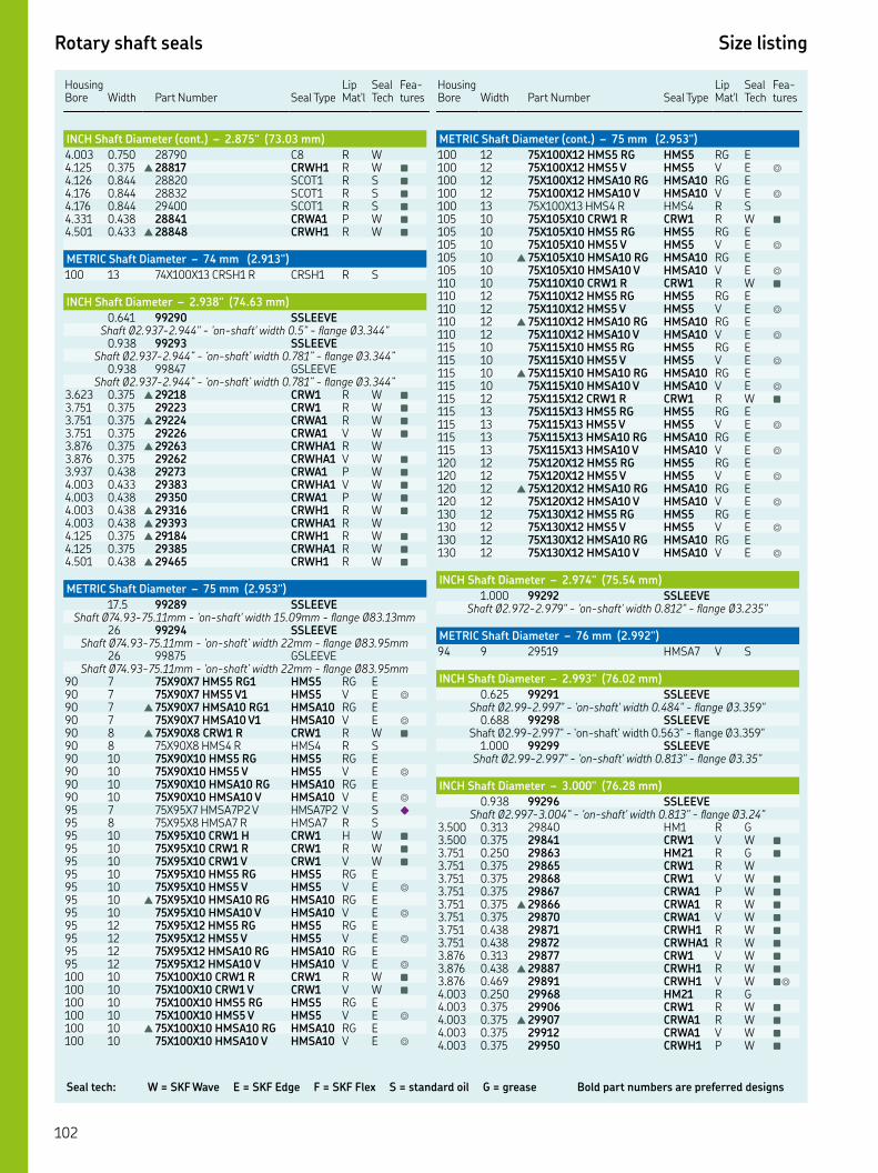
Seal tech: W = SKF Wave E = SKF Edge F = SKF Flex S = standard oil G = grease Bold part numbers are preferred designs
Rotary shaft seals Size listing
HousingBore Width
Part Number Seal Type
Lip Mat'l
Seal Tech
Fea-tures
INCH Shaft Diameter (cont.) – 2.875" (73.03 mm)
. . C R W. . ▲ CRWH R W ■
. . SCOT R S ■
. . SCOT R S ■
. . SCOT R S ■
. . CRWA P W ■
. . ▲ CRWH R W ■
METRIC Shaft Diameter – 74 mm (2.913")
XX CRSH R CRSH R S
INCH Shaft Diameter – 2.938" (74.63 mm)
. SSLEEVEShaft Ø.-." - 'on-shaft' width ." - flange Ø."
. SSLEEVEShaft Ø.-.” - ‘on-shaft’ width .” - flange Ø.”
. GSLEEVEShaft Ø.-.” - ‘on-shaft’ width .” - flange Ø.”
. . ▲ CRW R W ■
. . CRW R W ■
. . ▲ CRWA R W ■
. . CRWA V W ■
. . ▲ CRWHA R W. . CRWHA V W ■
. . CRWA P W ■
. . CRWHA V W ■
. . CRWA P W ■
. . ▲ CRWH R W ■
. . ▲ CRWHA R W. . ▲ CRWH R W ■
. . CRWHA R W ■
. . ▲ CRWH R W ■
METRIC Shaft Diameter – 75 mm (2.953")
. SSLEEVEShaft Ø.-.mm - 'on-shaft' width .mm - flange Ø.mm
SSLEEVEShaft Ø.-.mm - ‘on-shaft’ width mm - flange Ø.mm
GSLEEVEShaft Ø.-.mm - ‘on-shaft’ width mm - flange Ø.mm
XX HMS RG HMS RG E XX HMS V HMS V E ◎
▲ XX HMSA RG HMSA RG E XX HMSA V HMSA V E ◎
▲ XX CRW R CRW R W ■
XX HMS R HMS R S XX HMS RG HMS RG E XX HMS V HMS V E ◎
XX HMSA RG HMSA RG E XX HMSA V HMSA V E ◎
XX HMSAP V HMSAP V S ◆
XX HMSA R HMSA R S XX CRW H CRW H W ■
XX CRW R CRW R W ■
XX CRW V CRW V W ■
XX HMS RG HMS RG E XX HMS V HMS V E ◎
▲ XX HMSA RG HMSA RG E XX HMSA V HMSA V E ◎
XX HMS RG HMS RG E XX HMS V HMS V E ◎
XX HMSA RG HMSA RG E XX HMSA V HMSA V E ◎
XX CRW R CRW R W ■
XX CRW V CRW V W ■
XX HMS RG HMS RG E XX HMS V HMS V E ◎
▲ XX HMSA RG HMSA RG E XX HMSA V HMSA V E ◎
Housing Bore
Width
Part Number
Seal Type
Lip Mat'l
Seal Tech
Fea-tures
METRIC Shaft Diameter (cont.) – 75 mm (2.953")
XX HMS RG HMS RG E XX HMS V HMS V E ◎
XX HMSA RG HMSA RG E XX HMSA V HMSA V E ◎
XX HMS R HMS R S XX CRW R CRW R W ■
XX HMS RG HMS RG E XX HMS V HMS V E ◎
▲ XX HMSA RG HMSA RG E XX HMSA V HMSA V E ◎
XX CRW R CRW R W ■
XX HMS RG HMS RG E XX HMS V HMS V E ◎
▲ XX HMSA RG HMSA RG E XX HMSA V HMSA V E ◎
XX HMS RG HMS RG E XX HMS V HMS V E ◎
▲ XX HMSA RG HMSA RG E XX HMSA V HMSA V E ◎
XX CRW R CRW R W ■
XX HMS RG HMS RG E XX HMS V HMS V E ◎
XX HMSA RG HMSA RG E XX HMSA V HMSA V E ◎
XX HMS RG HMS RG E XX HMS V HMS V E ◎
▲ XX HMSA RG HMSA RG E XX HMSA V HMSA V E ◎
XX HMS RG HMS RG E XX HMS V HMS V E ◎
XX HMSA RG HMSA RG E XX HMSA V HMSA V E ◎
INCH Shaft Diameter – 2.974" (75.54 mm)
. SSLEEVEShaft Ø.-." - 'on-shaft' width ." - flange Ø."
METRIC Shaft Diameter – 76 mm (2.992")
HMSA V S
INCH Shaft Diameter – 2.993" (76.02 mm)
. SSLEEVEShaft Ø.-." - 'on-shaft' width ." - flange Ø."
. SSLEEVEShaft Ø.-." - 'on-shaft' width ." - flange Ø."
. SSLEEVEShaft Ø.-." - 'on-shaft' width ." - flange Ø."
INCH Shaft Diameter – 3.000" (76.28 mm)
. SSLEEVEShaft Ø.-." - 'on-shaft' width ." - flange Ø."
. . HM R G. . CRW V W ■
. . HM R G ■
. . CRW R W. . CRW V W ■
. . CRWA P W ■
. . ▲ CRWA R W ■
. . CRWA V W ■
. . CRWH R W ■
. . CRWHA R W ■
. . CRW V W ■
. . ▲ CRWH R W ■
. . CRWH V W ■◎
. . HM R G. . CRW R W ■
. . ▲ CRWA R W ■
. . CRWA V W ■
. . CRWH P W ■
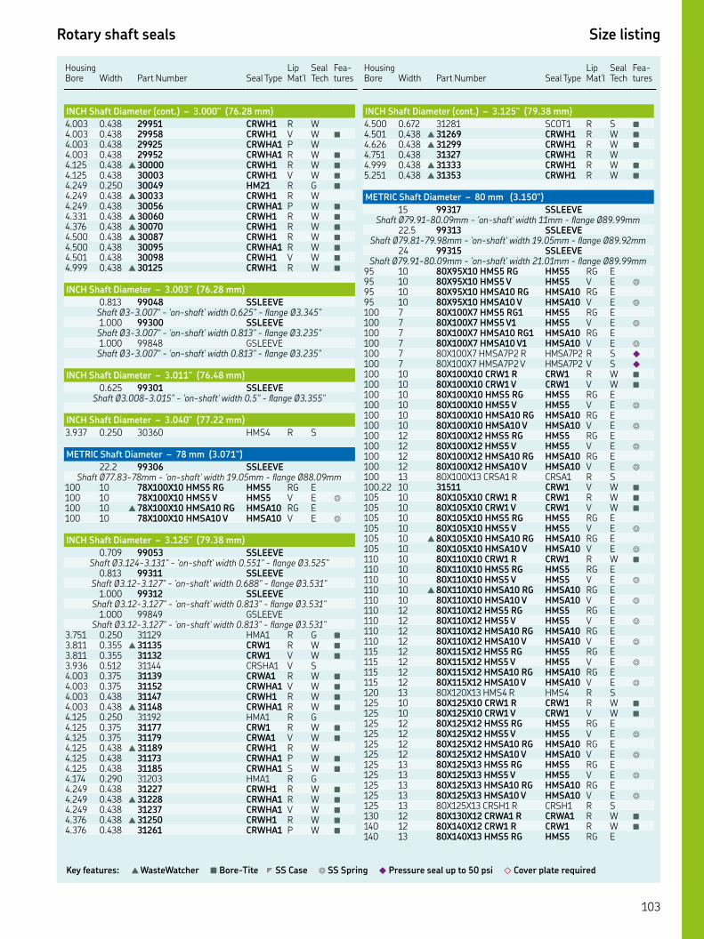
Rotary shaft seals Size listing
Key features: ▲ WasteWatcher ■ Bore-Tite ◤ SS Case ◎ SS Spring ◆ Pressure seal up to 50 psi ◇ Cover plate required
HousingBore Width
Part Number Seal Type
Lip Mat'l
Seal Tech
Fea-tures
INCH Shaft Diameter (cont.) – 3.000" (76.28 mm)
. . CRWH R W. . CRWH V W ■
. . CRWHA P W. . CRWHA R W ■
. . ▲ CRWH R W ■
. . CRWH V W ■
. . HM R G ■
. . ▲ CRWH R W. . CRWHA P W ■
. . ▲ CRWH R W ■
. . ▲ CRWH R W ■
. . ▲ CRWH R W ■
. . CRWHA R W ■
. . CRWH V W ■
. . ▲ CRWH R W ■
INCH Shaft Diameter – 3.003" (76.28 mm)
. SSLEEVEShaft Ø-." - 'on-shaft' width ." - flange Ø.". SSLEEVEShaft Ø-." - 'on-shaft' width ." - flange Ø.". GSLEEVEShaft Ø-." - 'on-shaft' width ." - flange Ø."
INCH Shaft Diameter – 3.011" (76.48 mm)
. SSLEEVEShaft Ø.-." - 'on-shaft' width ." - flange Ø."
INCH Shaft Diameter – 3.040" (77.22 mm)
. . HMS R S
METRIC Shaft Diameter – 78 mm (3.071")
. SSLEEVEShaft Ø.-mm - 'on-shaft' width .mm - flange Ø.mm
XX HMS RG HMS RG E XX HMS V HMS V E ◎
▲ XX HMSA RG HMSA RG E XX HMSA V HMSA V E ◎
INCH Shaft Diameter – 3.125" (79.38 mm)
. SSLEEVEShaft Ø.-." - 'on-shaft' width ." - flange Ø."
. SSLEEVEShaft Ø.-." - 'on-shaft' width ." - flange Ø."
. SSLEEVEShaft Ø.-." - 'on-shaft' width ." - flange Ø."
. GSLEEVEShaft Ø.-." - 'on-shaft' width ." - flange Ø."
. . HMA R G ■
. . ▲ CRW R W ■
. . CRW V W ■
. . CRSHA V S. . CRWA R W ■
. . CRWHA V W ■
. . CRWH R W ■
. . ▲ CRWHA R W ■
. . HMA R G. . CRW R W ■
. . CRWA V W ■
. . ▲ CRWH R W. . CRWHA P W ■
. . CRWHA S W ■
. . HMA R G. . CRWH R W ■
. . ▲ CRWHA R W ■
. . CRWHA V W ■
. . ▲ CRWH R W ■
. . CRWHA P W ■
Housing Bore
Width
Part Number
Seal Type
Lip Mat'l
Seal Tech
Fea-tures
INCH Shaft Diameter (cont.) – 3.125" (79.38 mm)
. . SCOT R S ■
. . ▲ CRWH R W ■
. . ▲ CRWH R W ■
. . CRWH R W. . ▲ CRWH R W ■
. . ▲ CRWH R W ■
METRIC Shaft Diameter – 80 mm (3.150")
SSLEEVEShaft Ø.-.mm - 'on-shaft' width mm - flange Ø.mm
. SSLEEVEShaft Ø.-.mm - 'on-shaft' width .mm - flange Ø.mm
SSLEEVEShaft Ø.-.mm - 'on-shaft' width .mm - flange Ø.mm
XX HMS RG HMS RG E XX HMS V HMS V E ◎
XX HMSA RG HMSA RG E XX HMSA V HMSA V E ◎
XX HMS RG HMS RG E XX HMS V HMS V E ◎
XX HMSA RG HMSA RG E XX HMSA V HMSA V E ◎
XX HMSAP R HMSAP R S ◆
XX HMSAP V HMSAP V S ◆
XX CRW R CRW R W ■
XX CRW V CRW V W ■
XX HMS RG HMS RG E XX HMS V HMS V E ◎
XX HMSA RG HMSA RG E XX HMSA V HMSA V E ◎
XX HMS RG HMS RG E XX HMS V HMS V E ◎
XX HMSA RG HMSA RG E XX HMSA V HMSA V E ◎
XX CRSA R CRSA R S. CRW V W ■
XX CRW R CRW R W ■
XX CRW V CRW V W ■
XX HMS RG HMS RG E XX HMS V HMS V E ◎
▲ XX HMSA RG HMSA RG E XX HMSA V HMSA V E ◎
XX CRW R CRW R W ■
XX HMS RG HMS RG E XX HMS V HMS V E ◎
▲ XX HMSA RG HMSA RG E XX HMSA V HMSA V E ◎
XX HMS RG HMS RG E XX HMS V HMS V E ◎
XX HMSA RG HMSA RG E XX HMSA V HMSA V E ◎
XX HMS RG HMS RG E XX HMS V HMS V E ◎
XX HMSA RG HMSA RG E XX HMSA V HMSA V E ◎
XX HMS R HMS R S XX CRW R CRW R W ■
XX CRW V CRW V W ■
XX HMS RG HMS RG E XX HMS V HMS V E ◎
XX HMSA RG HMSA RG E XX HMSA V HMSA V E ◎
XX HMS RG HMS RG E XX HMS V HMS V E ◎
XX HMSA RG HMSA RG E XX HMSA V HMSA V E ◎
XX CRSH R CRSH R S XX CRWA R CRWA R W ■
XX CRW R CRW R W ■
XX HMS RG HMS RG E
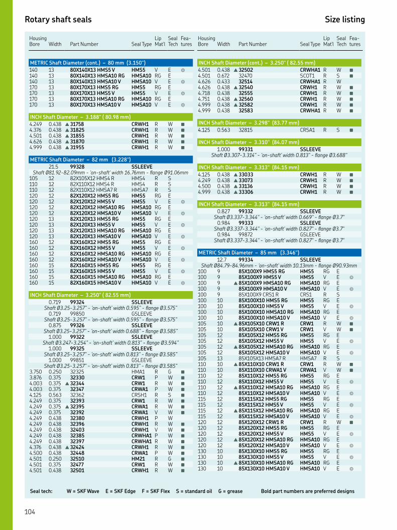
Seal tech: W = SKF Wave E = SKF Edge F = SKF Flex S = standard oil G = grease Bold part numbers are preferred designs
Rotary shaft seals Size listing
HousingBore Width
Part Number Seal Type
Lip Mat'l
Seal Tech
Fea-tures
METRIC Shaft Diameter (cont.) – 80 mm (3.150")
XX HMS V HMS V E ◎
XX HMSA RG HMSA RG E XX HMSA V HMSA V E ◎
XX HMS RG HMS RG E XX HMS V HMS V E ◎
XX HMSA RG HMSA RG E XX HMSA V HMSA V E ◎
INCH Shaft Diameter – 3.188" ( 80.98 mm)
. . ▲ CRWH R W ■
. . ▲ CRWH R W ■
. . ▲ CRWH R W ■
. . ▲ CRWH R W ■
. . ▲ CRWH R W ■
METRIC Shaft Diameter – 82 mm (3.228")
. SSLEEVEShaft Ø.-.mm - 'on-shaft' width .mm - flange Ø.mm
XX HMS R HMS R S XX HMS R HMS R S XX HMSA R HMSA R S XX HMS RG HMS RG E XX HMS V HMS V E ◎
XX HMSA RG HMSA RG E XX HMSA V HMSA V E ◎
XX HMS RG HMS RG E XX HMS V HMS V E ◎
XX HMSA RG HMSA RG E XX HMSA V HMSA V E ◎
XX HMS RG HMS RG E XX HMS V HMS V E ◎
XX HMSA RG HMSA RG E XX HMSA V HMSA V E ◎
XX HMS RG HMS RG E XX HMS V HMS V E ◎
XX HMSA RG HMSA RG E XX HMSA V HMSA V E ◎
INCH Shaft Diameter – 3.250" ( 82.55 mm)
. SSLEEVEShaft Ø.-.” - ‘on-shaft’ width .” - flange Ø.”
. GSLEEVEShaft Ø.-.” - ‘on-shaft’ width .” - flange Ø.”
. SSLEEVEShaft Ø.-.” - ‘on-shaft’ width .” - flange Ø.”
. SSLEEVEShaft Ø.-.” - ‘on-shaft’ width .” - flange Ø.”
. SSLEEVEShaft Ø.-.” - ‘on-shaft’ width .” - flange Ø.”
. GSLEEVEShaft Ø.-.” - ‘on-shaft’ width .” - flange Ø.”
. . HMA R G ■
. . CRW P W ■
. . ▲ CRW R W ■
. . CRWA P W ■
. . CRSH R S ■
. . CRW R W ■
. . ▲ CRWA R W ■
. . CRWA V W ■
. . CRWH P W. . CRWH R W ■
. . CRWH V W ■
. . CRWHA P W ■
. . CRWHA R W ■
. . ▲ CRWH R W ■
. . CRWA P W ■
. . HM R G ■
. . CRW R W ■
. . CRWH R W ■
Housing Bore
Width
Part Number
Seal Type
Lip Mat'l
Seal Tech
Fea-tures
INCH Shaft Diameter (cont.) – 3.250" ( 82.55 mm)
. . ▲ CRWHA R W ■
. . SCOT R S ■
. . CRWHA R W. . ▲ CRWH R W ■
. . CRWH R W ■
. . ▲ CRWH R W ■
. . ▲ CRWH R W ■
. . CRWHA R W ■
INCH Shaft Diameter – 3.298" (83.77 mm)
. . CRSA R S ■
INCH Shaft Diameter – 3.310" (84.07 mm)
. SSLEEVEShaft Ø.-." - 'on-shaft' width ." - flange Ø."
INCH Shaft Diameter – 3.313" (84.15 mm)
. . ▲ CRWH R W ■
. . ▲ CRWH R W ■
. . ▲ CRWH R W ■
. . ▲ CRWH R W ■
INCH Shaft Diameter – 3.313" (84.15 mm)
. SSLEEVEShaft Ø.-." - 'on-shaft' width ." - flange Ø."
. SSLEEVEShaft Ø.-." - 'on-shaft' width ." - flange Ø."
. GSLEEVEShaft Ø.-." - 'on-shaft' width ." - flange Ø."
METRIC Shaft Diameter – 85 mm (3.346")
. SSLEEVEShaft Ø.-.mm - 'on-shaft' width .mm - flange Ø.mm
XX HMS RG HMS RG E XX HMS V HMS V E ◎
▲ XX HMSA RG HMSA RG E XX HMSA V HMSA V E ◎
XX CRS R CRS R S XX HMS RG HMS RG E XX HMS V HMS V E ◎
XX HMSA RG HMSA RG E XX HMSA V HMSA V E ◎
▲ XX CRW R CRW R W ■
XX CRW V CRW V W ■
XX HMS RG HMS RG E XX HMS V HMS V E ◎
▲ XX HMSA RG HMSA RG E XX HMSA V HMSA V E ◎
XX HMSA R HMSA R S ▲ XX CRW R CRW R W ■
XX CRWA V CRWA V W ■
XX HMS RG HMS RG E XX HMS V HMS V E ◎
▲ XX HMSA RG HMSA RG E XX HMSA V HMSA V E ◎
XX HMS RG HMS RG E XX HMS V HMS V E ◎
▲ XX HMSA RG HMSA RG E XX HMSA V HMSA V E ◎
XX CRW R CRW R W ■
XX HMS RG HMS RG E XX HMS V HMS V E ◎
▲ XX HMSA RG HMSA RG E XX HMSA V HMSA V E ◎
XX HMS RG HMS RG E XX HMS V HMS V E ◎
▲ XX HMSA RG HMSA RG E XX HMSA V HMSA V E ◎
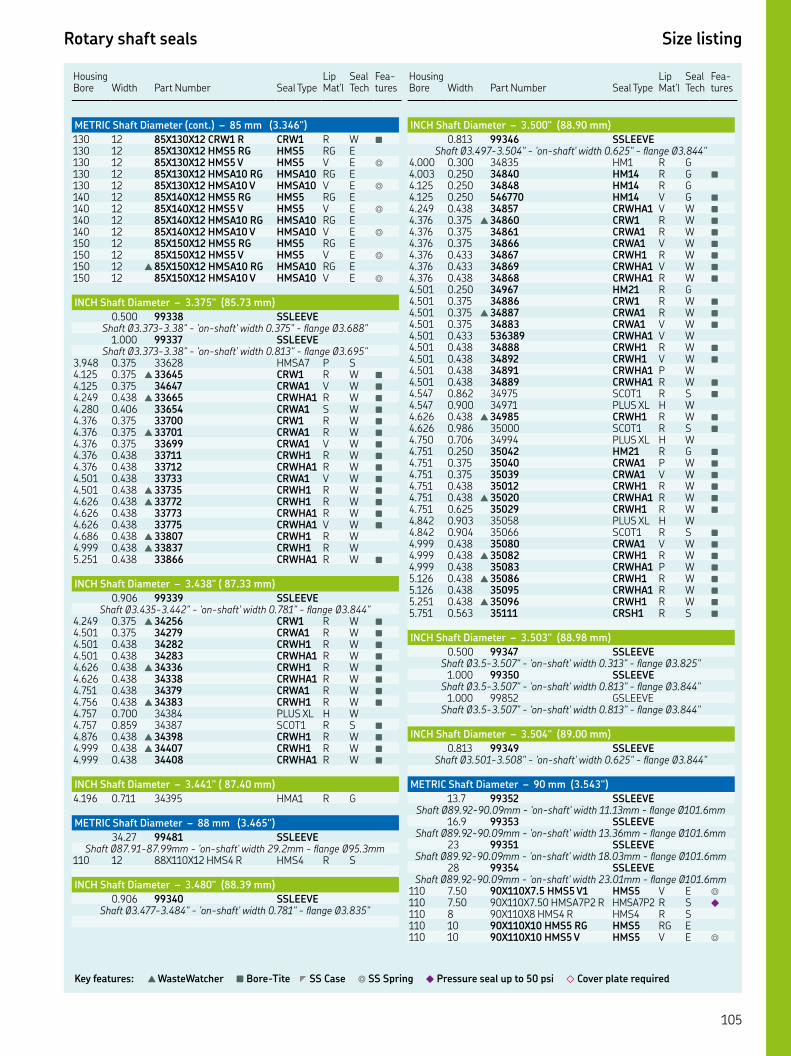
Rotary shaft seals Size listing
Key features: ▲ WasteWatcher ■ Bore-Tite ◤ SS Case ◎ SS Spring ◆ Pressure seal up to 50 psi ◇ Cover plate required
HousingBore Width
Part Number Seal Type
Lip Mat'l
Seal Tech
Fea-tures
METRIC Shaft Diameter (cont.) – 85 mm (3.346")
XX CRW R CRW R W ■
XX HMS RG HMS RG E XX HMS V HMS V E ◎
XX HMSA RG HMSA RG E XX HMSA V HMSA V E ◎
XX HMS RG HMS RG E XX HMS V HMS V E ◎
XX HMSA RG HMSA RG E XX HMSA V HMSA V E ◎
XX HMS RG HMS RG E XX HMS V HMS V E ◎
▲ XX HMSA RG HMSA RG E XX HMSA V HMSA V E ◎
INCH Shaft Diameter – 3.375" (85.73 mm)
. SSLEEVEShaft Ø.-." - 'on-shaft' width ." - flange Ø."
. SSLEEVEShaft Ø.-." - 'on-shaft' width ." - flange Ø."
. . HMSA P S. . ▲ CRW R W ■
. . CRWA V W ■
. . ▲ CRWHA R W ■
. . CRWA S W ■
. . CRW R W ■
. . ▲ CRWA R W ■
. . CRWA V W ■
. . CRWH R W ■
. . CRWHA R W ■
. . CRWA V W ■
. . ▲ CRWH R W ■
. . ▲ CRWH R W ■
. . CRWHA R W ■
. . CRWHA V W ■
. . ▲ CRWH R W. . ▲ CRWH R W. . CRWHA R W ■
INCH Shaft Diameter – 3.438" ( 87.33 mm)
. SSLEEVEShaft Ø.-." - 'on-shaft' width ." - flange Ø."
. . ▲ CRW R W ■
. . CRWA R W ■
. . CRWH R W ■
. . CRWHA R W ■
. . ▲ CRWH R W ■
. . CRWHA R W ■
. . CRWA R W ■
. . ▲ CRWH R W ■
. . PLUS XL H W. . SCOT R S ■
. . ▲ CRWH R W ■
. . ▲ CRWH R W ■
. . CRWHA R W ■
INCH Shaft Diameter – 3.441" ( 87.40 mm)
. . HMA R G
METRIC Shaft Diameter – 88 mm (3.465")
. SSLEEVEShaft Ø.-.mm - 'on-shaft' width .mm - flange Ø.mm
XX HMS R HMS R S
INCH Shaft Diameter – 3.480" (88.39 mm)
. SSLEEVEShaft Ø.-." - 'on-shaft' width ." - flange Ø."
Housing Bore
Width
Part Number
Seal Type
Lip Mat'l
Seal Tech
Fea-tures
INCH Shaft Diameter – 3.500" (88.90 mm)
. SSLEEVEShaft Ø.-." - 'on-shaft' width ." - flange Ø."
. . HM R G. . HM R G ■
. . HM R G. . HM V G ■
. . CRWHA V W ■
. . ▲ CRW R W ■
. . CRWA R W ■
. . CRWA V W ■
. . CRWH R W ■
. . CRWHA V W ■
. . CRWHA R W ■
. . HM R G. . CRW R W ■
. . ▲ CRWA R W ■
. . CRWA V W ■
. . CRWHA V W. . CRWH R W ■
. . CRWH V W ■
. . CRWHA P W. . CRWHA R W ■
. . SCOT R S ■
. . PLUS XL H W. . ▲ CRWH R W ■
. . SCOT R S ■
. . PLUS XL H W. . HM R G ■
. . CRWA P W ■
. . CRWA V W ■
. . CRWH R W ■
. . ▲ CRWHA R W ■
. . CRWH R W ■
. . PLUS XL H W. . SCOT R S ■
. . CRWA V W ■
. . ▲ CRWH R W ■
. . CRWHA P W ■
. . ▲ CRWH R W ■
. . CRWHA R W ■
. . ▲ CRWH R W ■
. . CRSH R S ■
INCH Shaft Diameter – 3.503" (88.98 mm)
. SSLEEVEShaft Ø.-." - 'on-shaft' width ." - flange Ø."
. SSLEEVEShaft Ø.-." - 'on-shaft' width ." - flange Ø."
. GSLEEVEShaft Ø.-." - 'on-shaft' width ." - flange Ø."
INCH Shaft Diameter – 3.504" (89.00 mm)
. SSLEEVEShaft Ø.-." - 'on-shaft' width ." - flange Ø."
METRIC Shaft Diameter – 90 mm (3.543")
. SSLEEVEShaft Ø.-.mm - 'on-shaft' width .mm - flange Ø.mm
. SSLEEVEShaft Ø.-.mm - 'on-shaft' width .mm - flange Ø.mm
SSLEEVEShaft Ø.-.mm - 'on-shaft' width .mm - flange Ø.mm
SSLEEVEShaft Ø.-.mm - 'on-shaft' width .mm - flange Ø.mm
. XX. HMS V HMS V E ◎
. XX. HMSAP R HMSAP R S ◆
XX HMS R HMS R S XX HMS RG HMS RG E XX HMS V HMS V E ◎
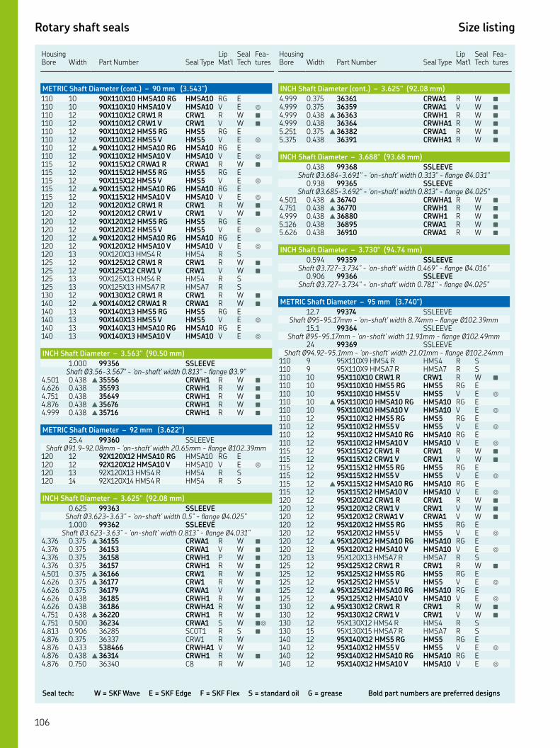
Seal tech: W = SKF Wave E = SKF Edge F = SKF Flex S = standard oil G = grease Bold part numbers are preferred designs
Rotary shaft seals Size listing
HousingBore Width
Part Number Seal Type
Lip Mat'l
Seal Tech
Fea-tures
METRIC Shaft Diameter (cont.) – 90 mm (3.543")
XX HMSA RG HMSA RG E XX HMSA V HMSA V E ◎
XX CRW R CRW R W ■
XX CRW V CRW V W ■
XX HMS RG HMS RG E XX HMS V HMS V E ◎
▲ XX HMSA RG HMSA RG E XX HMSA V HMSA V E ◎
XX CRWA R CRWA R W ■
XX HMS RG HMS RG E XX HMS V HMS V E ◎
▲ XX HMSA RG HMSA RG E XX HMSA V HMSA V E ◎
XX CRW R CRW R W ■
XX CRW V CRW V W ■
XX HMS RG HMS RG E XX HMS V HMS V E ◎
▲ XX HMSA RG HMSA RG E XX HMSA V HMSA V E ◎
XX HMS R HMS R S XX CRW R CRW R W ■
XX CRW V CRW V W ■
XX HMS R HMS R S XX HMSA R HMSA R S XX CRW R CRW R W ■
▲ XX CRWA R CRWA R W ■
XX HMS RG HMS RG E XX HMS V HMS V E ◎
XX HMSA RG HMSA RG E XX HMSA V HMSA V E ◎
INCH Shaft Diameter – 3.563" (90.50 mm)
. SSLEEVEShaft Ø.-." - 'on-shaft' width ." - flange Ø."
. . ▲ CRWH R W ■
. . CRWH R W ■
. . CRWH R W ■
. . ▲ CRWH R W ■
. . ▲ CRWH R W ■
METRIC Shaft Diameter – 92 mm (3.622")
. SSLEEVEShaft Ø.-.mm - 'on-shaft' width .mm - flange Ø.mm
XX HMSA RG HMSA RG E XX HMSA V HMSA V E ◎
XX HMS R HMS R S XX HMS R HMS R S
INCH Shaft Diameter – 3.625" (92.08 mm)
. SSLEEVEShaft Ø.-.” - ‘on-shaft’ width .” - flange Ø.”. SSLEEVE
Shaft Ø.-.” - ‘on-shaft’ width .” - flange Ø.”. . ▲ CRWA R W ■
. . CRWA V W ■
. . CRWH P W ■
. . CRWH R W ■
. . ▲ CRW R W ■
. . ▲ CRW R W ■
. . CRWA V W ■
. . CRWH R W ■
. . CRWHA R W ■
. . ▲ CRWH R W ■
. . CRWA S W ■◎
. . SCOT R S ■
. . CRW R W. . CRWHA V W. . ▲ CRWH R W ■
. . C R W
Housing Bore
Width
Part Number
Seal Type
Lip Mat'l
Seal Tech
Fea-tures
INCH Shaft Diameter (cont.) – 3.625" (92.08 mm)
. . CRWA R W ■
. . CRWA V W ■
. . ▲ CRWH R W ■
. . CRWHA R W ■
. . ▲ CRWA R W ■
. . CRWHA R W ■
INCH Shaft Diameter – 3.688" (93.68 mm)
. SSLEEVEShaft Ø.-." - 'on-shaft' width ." - flange Ø."
. SSLEEVEShaft Ø.-." - 'on-shaft' width ." - flange Ø."
. . ▲ CRWHA R W ■
. . ▲ CRWH R W ■
. . ▲ CRWH R W ■
. . CRWA R W ■
. . CRWA R W ■
INCH Shaft Diameter – 3.730" (94.74 mm)
. SSLEEVEShaft Ø.-." - 'on-shaft' width ." - flange Ø."
. SSLEEVEShaft Ø.-." - 'on-shaft' width ." - flange Ø."
METRIC Shaft Diameter – 95 mm (3.740")
. SSLEEVEShaft Ø-.mm - 'on-shaft' width .mm - flange Ø.mm
. SSLEEVEShaft Ø-.mm - 'on-shaft' width .mm - flange Ø.mm
SSLEEVEShaft Ø.-.mm - 'on-shaft' width .mm - flange Ø.mm
XX HMS R HMS R S XX HMSA R HMSA R S XX CRW R CRW R W ■
XX HMS RG HMS RG E XX HMS V HMS V E ◎
▲ XX HMSA RG HMSA RG E XX HMSA V HMSA V E ◎
XX HMS RG HMS RG E XX HMS V HMS V E ◎
XX HMSA RG HMSA RG E XX HMSA V HMSA V E ◎
XX CRW R CRW R W ■
XX CRW V CRW V W ■
XX HMS RG HMS RG E XX HMS V HMS V E ◎
▲ XX HMSA RG HMSA RG E XX HMSA V HMSA V E ◎
XX CRW R CRW R W ■
XX CRW V CRW V W ■
XX CRWA V CRWA V W ■
XX HMS RG HMS RG E XX HMS V HMS V E ◎
▲ XX HMSA RG HMSA RG E XX HMSA V HMSA V E ◎
XX HMSA R HMSA R S XX CRW R CRW R W ■
XX HMS RG HMS RG E XX HMS V HMS V E ◎
▲ XX HMSA RG HMSA RG E XX HMSA V HMSA V E ◎
▲ XX CRW R CRW R W ■
XX CRW V CRW V W ■
XX HMS R HMS R S XX HMSA R HMSA R S XX HMS RG HMS RG E XX HMS V HMS V E ◎
XX HMSA RG HMSA RG E XX HMSA V HMSA V E ◎
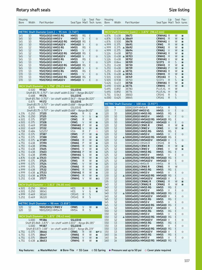
Rotary shaft seals Size listing
Key features: ▲ WasteWatcher ■ Bore-Tite ◤ SS Case ◎ SS Spring ◆ Pressure seal up to 50 psi ◇ Cover plate required
HousingBore Width
Part Number Seal Type
Lip Mat'l
Seal Tech
Fea-tures
METRIC Shaft Diameter (cont.) – 95 mm (3.740")
XX HMS RG HMS RG E XX HMS V HMS V E ◎
XX HMSA RG HMSA RG E XX HMSA V HMSA V E ◎
XX HMS RG HMS RG E XX HMS V HMS V E ◎
XX HMSA RG HMSA RG E XX HMSA V HMSA V E ◎
XX HMS RG HMS RG E XX HMS V HMS V E ◎
XX HMSA RG HMSA RG E XX HMSA V HMSA V E ◎
XX HMS RG HMS RG E XX HMS V HMS V E ◎
XX HMSA RG HMSA RG E XX HMSA V HMSA V E ◎
INCH Shaft Diameter – 3.750" (95.25 mm)
. SSLEEVEShaft Ø.-." - 'on-shaft' width ." - flange Ø."
. SSLEEVEShaft Ø.-." - 'on-shaft' width ." - flange Ø."
. SSLEEVEShaft Ø.-." - 'on-shaft' width ." - flange Ø."
. GSLEEVEShaft Ø.-." - 'on-shaft' width ." - flange Ø."
. . HM R G ■
. . HM V G ■
. . CRW R W. . CRW V W ■
. . CRWHA P W ■
. . CRWHA V W ■
. . HS R F ◇
. . CRW P W ■
. . CRW R W ■
. . ▲ CRWA R W ■
. . CRWA P W ■
. . CRWH R W ■
. . CRWH V W ■
. . CRWHA P W ■
. . CRWHA S W ■
. . ▲ CRWH R W ■
. . CRW R W ■
. . CRW V W ■
. . CRWA R W ■
. . CRWH R W ■
. . ▲ CRWHA R W ■
. . ▲ CRWH R W ■
. . CRWH V W ■◎
INCH Shaft Diameter – 3.813" (96.85 mm)
. . HD R G ■
. . HD V G ■
. . CRSH R S. . CRSH R S
METRIC Shaft Diameter – 98 mm (3.858")
XX CRW V CRW V W ■
XX HMS R HMS R S
INCH Shaft Diameter – 3.875" (98.43 mm)
. SSLEEVEShaft Ø.-." - 'on-shaft' width ." - flange Ø."
. SSLEEVEShaft Ø.-." - 'on-shaft' width ." - flange Ø."
. . CRW R W ■◤◎
. . CRWA R W ■
. . CRWA V W ■
. . ▲ CRWH R W ■
Housing Bore
Width
Part Number
Seal Type
Lip Mat'l
Seal Tech
Fea-tures
INCH Shaft Diameter (cont.) – 3.875" (98.43 mm)
. . CRWHA R W ■
. . ▲ CRWH R W ■
. . CRWHA V W ■
. . CRW R W ■
. . ▲ CRWA R W ■
. . CRWA V W ■
. . CRWHA R W ■
. . ▲ CRWH R W ■
. . CRWHA V W ■
. . SCOT R S ■
. . CRWH R W ■
. . CRWHA P W ■
. . ▲ CRWHA R W ■
. . ▲ CRWH R W ■
. . CRSHA R S ■
. . SCOT R S ■
. . CRWHA R W ■
. . ▲ CRWH R W ■
. . PLUS XL H W. . PLUS XL H W. . CRSH R S. . CRSA R S
METRIC Shaft Diameter – 100 mm (3.937")
XX HMS R HMS R S XX HMS V HMS V E ◎
XX HMS RG HMS RG E XX HMS V HMS V E ◎
XX HMSA RG HMSA RG E XX HMSA V HMSA V E ◎
XX CRW R CRW R W ■
XX CRW V CRW V W ■
XX HMS RG HMS RG E XX HMS V HMS V E ◎
▲ XX HMSA RG HMSA RG E XX HMSA V HMSA V E ◎
XX CRSH R CRSH R S XX CRW R CRW R W ■
XX CRW V CRW V W ■
XX HMS RG HMS RG E XX HMS V HMS V E ◎
▲ XX HMSA RG HMSA RG E XX HMSA V HMSA V E ◎
XX HMS R HMS R S XX CRW R CRW R W XX HMS RG HMS RG E XX HMS V HMS V E ◎
▲ XX HMSA RG HMSA RG E XX HMSA V HMSA V E ◎
XX CRWA R CRWA R W ■
XX CRWA R CRWA R W ■
XX HMS RG HMS RG E XX HMS V HMS V E ◎
▲ XX HMSA RG HMSA RG E XX HMSA V HMSA V E ◎
XX HMS RG HMS RG E XX HMS V HMS V E ◎
XX HMSA RG HMSA RG E XX HMSA V HMSA V E ◎
XX HMS RG HMS RG E XX HMS V HMS V E ◎
▲ XX HMSA RG HMSA RG E XX HMSA V HMSA V E ◎
XX HMS RG HMS RG E XX HMS V HMS V E ◎
XX HMSA RG HMSA RG E XX HMSA V HMSA V E ◎
XX HMS RG HMS RG E XX HMS V HMS V E ◎
XX HMSA RG HMSA RG E
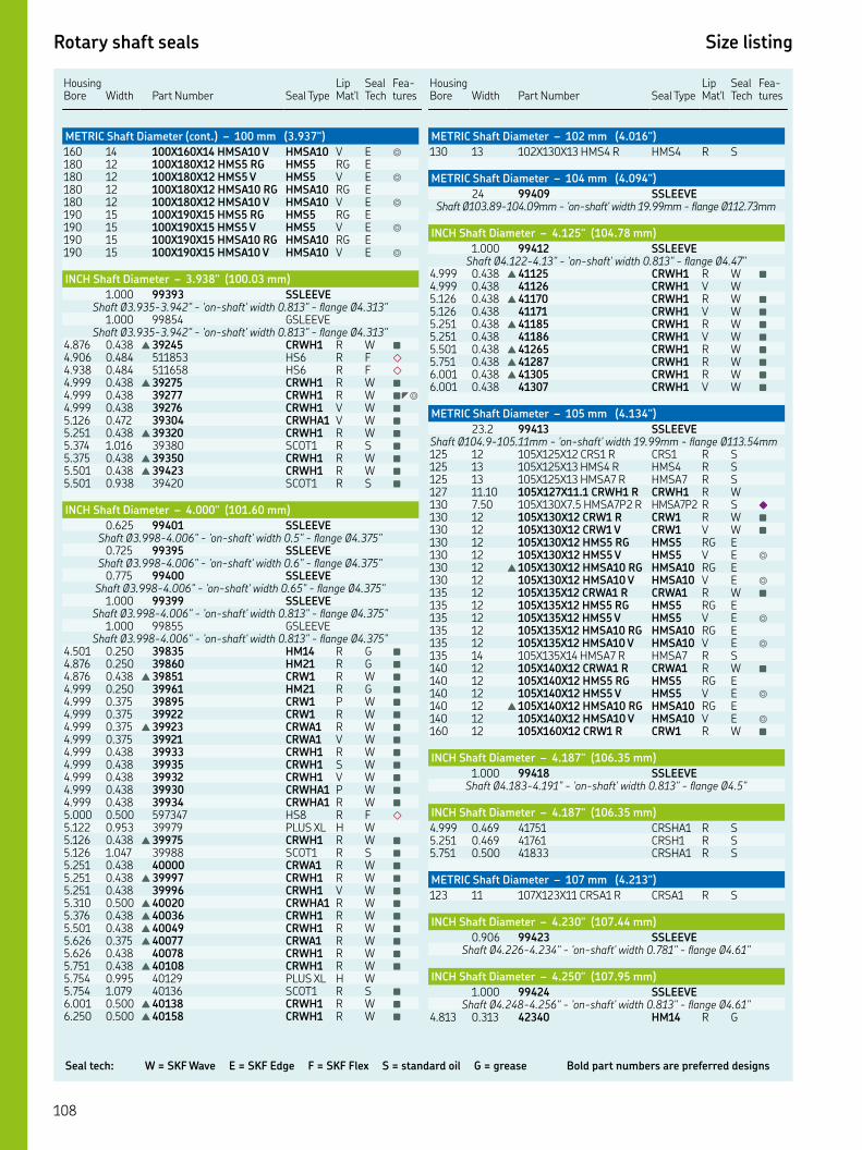
Seal tech: W = SKF Wave E = SKF Edge F = SKF Flex S = standard oil G = grease Bold part numbers are preferred designs
Rotary shaft seals Size listing
HousingBore Width
Part Number Seal Type
Lip Mat'l
Seal Tech
Fea-tures
METRIC Shaft Diameter (cont.) – 100 mm (3.937")
XX HMSA V HMSA V E ◎
XX HMS RG HMS RG E XX HMS V HMS V E ◎
XX HMSA RG HMSA RG E XX HMSA V HMSA V E ◎
XX HMS RG HMS RG E XX HMS V HMS V E ◎
XX HMSA RG HMSA RG E XX HMSA V HMSA V E ◎
INCH Shaft Diameter – 3.938" (100.03 mm)
. SSLEEVEShaft Ø.-." - 'on-shaft' width ." - flange Ø."
. GSLEEVEShaft Ø.-." - 'on-shaft' width ." - flange Ø."
. . ▲ CRWH R W ■
. . HS R F ◇
. . HS R F ◇
. . ▲ CRWH R W ■
. . CRWH R W ■◤◎
. . CRWH V W ■
. . CRWHA V W ■
. . ▲ CRWH R W ■
. . SCOT R S ■
. . ▲ CRWH R W ■
. . ▲ CRWH R W ■
. . SCOT R S ■
INCH Shaft Diameter – 4.000" (101.60 mm)
. SSLEEVEShaft Ø.-." - 'on-shaft' width ." - flange Ø."
. SSLEEVEShaft Ø.-." - 'on-shaft' width ." - flange Ø."
. SSLEEVEShaft Ø.-." - 'on-shaft' width ." - flange Ø."
. SSLEEVEShaft Ø.-." - 'on-shaft' width ." - flange Ø."
. GSLEEVEShaft Ø.-." - 'on-shaft' width ." - flange Ø."
. . HM R G ■
. . HM R G ■
. . ▲ CRW R W ■
. . HM R G ■
. . CRW P W ■
. . CRW R W ■
. . ▲ CRWA R W ■
. . CRWA V W ■
. . CRWH R W ■
. . CRWH S W ■
. . CRWH V W ■
. . CRWHA P W ■
. . CRWHA R W ■
. . HS R F ◇
. . PLUS XL H W. . ▲ CRWH R W ■
. . SCOT R S ■
. . CRWA R W ■
. . ▲ CRWH R W ■
. . CRWH V W ■
. . ▲ CRWHA R W ■
. . ▲ CRWH R W ■
. . ▲ CRWH R W ■
. . ▲ CRWA R W ■
. . CRWH R W ■
. . ▲ CRWH R W ■
. . PLUS XL H W. . SCOT R S ■
. . ▲ CRWH R W ■
. . ▲ CRWH R W ■
Housing Bore
Width
Part Number
Seal Type
Lip Mat'l
Seal Tech
Fea-tures
METRIC Shaft Diameter – 102 mm (4.016")
XX HMS R HMS R S
METRIC Shaft Diameter – 104 mm (4.094")
SSLEEVEShaft Ø.-.mm - 'on-shaft' width .mm - flange Ø.mm
INCH Shaft Diameter – 4.125" (104.78 mm)
. SSLEEVEShaft Ø.-." - 'on-shaft' width ." - flange Ø."
. . ▲ CRWH R W ■
. . CRWH V W. . ▲ CRWH R W ■
. . CRWH V W ■
. . ▲ CRWH R W ■
. . CRWH V W ■
. . ▲ CRWH R W ■
. . ▲ CRWH R W ■
. . ▲ CRWH R W ■
. . CRWH V W ■
METRIC Shaft Diameter – 105 mm (4.134")
. SSLEEVEShaft Ø.-.mm - 'on-shaft' width .mm - flange Ø.mm XX CRS R CRS R S XX HMS R HMS R S XX HMSA R HMSA R S . XX. CRWH R CRWH R W . XX. HMSAP R HMSAP R S ◆
XX CRW R CRW R W ■
XX CRW V CRW V W ■
XX HMS RG HMS RG E XX HMS V HMS V E ◎
▲ XX HMSA RG HMSA RG E XX HMSA V HMSA V E ◎
XX CRWA R CRWA R W ■
XX HMS RG HMS RG E XX HMS V HMS V E ◎
XX HMSA RG HMSA RG E XX HMSA V HMSA V E ◎
XX HMSA R HMSA R S XX CRWA R CRWA R W ■
XX HMS RG HMS RG E XX HMS V HMS V E ◎
▲ XX HMSA RG HMSA RG E XX HMSA V HMSA V E ◎
XX CRW R CRW R W ■
INCH Shaft Diameter – 4.187" (106.35 mm)
. SSLEEVEShaft Ø.-." - 'on-shaft' width ." - flange Ø."
INCH Shaft Diameter – 4.187" (106.35 mm)
. . CRSHA R S. . CRSH R S. . CRSHA R S
METRIC Shaft Diameter – 107 mm (4.213")
XX CRSA R CRSA R S
INCH Shaft Diameter – 4.230" (107.44 mm)
. SSLEEVEShaft Ø.-." - 'on-shaft' width ." - flange Ø."
INCH Shaft Diameter – 4.250" (107.95 mm)
. SSLEEVEShaft Ø.-." - 'on-shaft' width ." - flange Ø."
. . HM R G
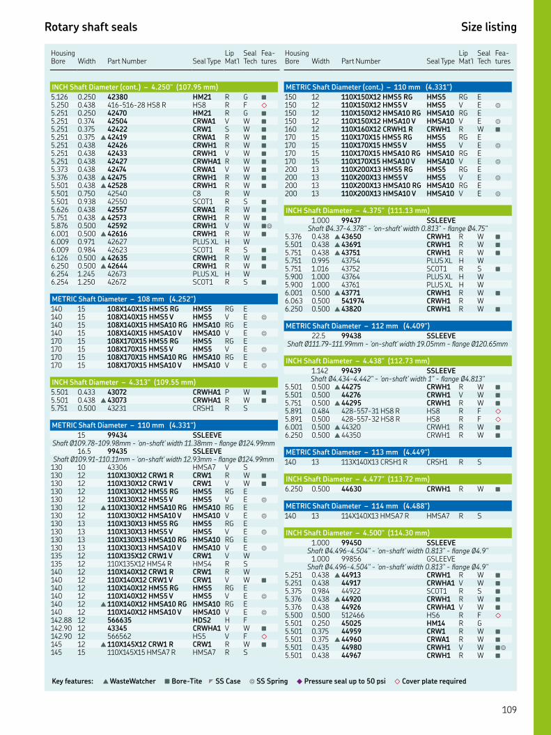
Rotary shaft seals Size listing
Key features: ▲ WasteWatcher ■ Bore-Tite ◤ SS Case ◎ SS Spring ◆ Pressure seal up to 50 psi ◇ Cover plate required
HousingBore Width
Part Number Seal Type
Lip Mat'l
Seal Tech
Fea-tures
INCH Shaft Diameter (cont.) – 4.250" (107.95 mm)
. . HM R G ■
. . -- HS R HS R F ◇
. . HM R G ■
. . CRWA V W ■
. . CRW S W ■
. . ▲ CRWA R W ■
. . CRWH R W ■
. . CRWH V W ■
. . CRWHA R W ■
. . CRWA V W ■
. . ▲ CRWH R W ■
. . ▲ CRWH R W ■
. . C R W. . SCOT R S ■
. . CRWA R W ■
. . ▲ CRWH R W ■
. . CRWH V W ■◎
. . ▲ CRWH R W ■
. . PLUS XL H W. . SCOT R S ■
. . ▲ CRWH R W ■
. . ▲ CRWH R W ■
. . PLUS XL H W. . SCOT R S ■
METRIC Shaft Diameter – 108 mm (4.252")
XX HMS RG HMS RG E XX HMS V HMS V E ◎
XX HMSA RG HMSA RG E XX HMSA V HMSA V E ◎
XX HMS RG HMS RG E XX HMS V HMS V E ◎
XX HMSA RG HMSA RG E XX HMSA V HMSA V E ◎
INCH Shaft Diameter – 4.313" (109.55 mm)
. . CRWHA P W ■
. . ▲ CRWHA R W ■
. . CRSH R S
METRIC Shaft Diameter – 110 mm (4.331")
SSLEEVEShaft Ø.-.mm - 'on-shaft' width .mm - flange Ø.mm
. SSLEEVEShaft Ø.-.mm - 'on-shaft' width .mm - flange Ø.mm
HMSA V S XX CRW R CRW R W ■
XX CRW V CRW V W ■
XX HMS RG HMS RG E XX HMS V HMS V E ◎
▲ XX HMSA RG HMSA RG E XX HMSA V HMSA V E ◎
XX HMS RG HMS RG E XX HMS V HMS V E ◎
XX HMSA RG HMSA RG E XX HMSA V HMSA V E ◎
XX CRW V CRW V W XX HMS R HMS R S XX CRW R CRW R W XX CRW V CRW V W ■
XX HMS RG HMS RG E XX HMS V HMS V E ◎
▲ XX HMSA RG HMSA RG E XX HMSA V HMSA V E ◎
. HDS H F. CRWHA V W ■
. HS V F ◇
▲ XX CRW R CRW R W ■
XX HMSA R HMSA R S
Housing Bore
Width
Part Number
Seal Type
Lip Mat'l
Seal Tech
Fea-tures
METRIC Shaft Diameter (cont.) – 110 mm (4.331")
XX HMS RG HMS RG E XX HMS V HMS V E ◎
XX HMSA RG HMSA RG E XX HMSA V HMSA V E ◎
XX CRWH R CRWH R W ■
XX HMS RG HMS RG E XX HMS V HMS V E ◎
XX HMSA RG HMSA RG E XX HMSA V HMSA V E ◎
XX HMS RG HMS RG E XX HMS V HMS V E ◎
XX HMSA RG HMSA RG E XX HMSA V HMSA V E ◎
INCH Shaft Diameter – 4.375" (111.13 mm)
. SSLEEVEShaft Ø.-." - 'on-shaft' width ." - flange Ø."
. . ▲ CRWH R W ■
. . ▲ CRWH R W ■
. . ▲ CRWH R W ■
. . PLUS XL H W. . SCOT R S ■
. . PLUS XL H W. . PLUS XL H W. . ▲ CRWH R W ■
. . CRWH R W. . ▲ CRWH R W ■
METRIC Shaft Diameter – 112 mm (4.409")
. SSLEEVEShaft Ø.-.mm - 'on-shaft' width .mm - flange Ø.mm
INCH Shaft Diameter – 4.438" (112.73 mm)
. SSLEEVEShaft Ø.-." - 'on-shaft' width " - flange Ø."
. . ▲ CRWH R W ■
. . CRWH V W ■
. . ▲ CRWH R W ■
. . -- HS R HS R F ◇
. . -- HS R HS R F ◇
. . ▲ CRWH R W ■
. . ▲ CRWH R W ■
METRIC Shaft Diameter – 113 mm (4.449")
XX CRSH R CRSH R S
INCH Shaft Diameter – 4.477" (113.72 mm)
. . CRWH R W ■
METRIC Shaft Diameter – 114 mm (4.488")
XX HMSA R HMSA R S
INCH Shaft Diameter – 4.500" (114.30 mm)
. SSLEEVEShaft Ø.-." - 'on-shaft' width ." - flange Ø."
. GSLEEVEShaft Ø.-." - 'on-shaft' width ." - flange Ø."
. . ▲ CRWH R W ■
. . CRWHA V W ■
. . SCOT R S ■
. . ▲ CRWH R W ■
. . CRWHA V W ■
. . HS R F ◇
. . HM R G. . CRW R W ■
. . ▲ CRWA R W ■
. . CRWH V W ■◎
. . CRWH R W ■

Seal tech: W = SKF Wave E = SKF Edge F = SKF Flex S = standard oil G = grease Bold part numbers are preferred designs
Rotary shaft seals Size listing
HousingBore Width
Part Number Seal Type
Lip Mat'l
Seal Tech
Fea-tures
INCH Shaft Diameter (cont.) – 4.500" (114.30 mm)
. . CRWH V W ■
. . CRWHA R W ■
. . ▲ CRWH R W ■
. . CRWHA V W ■
. . CRWA V W ■
. . ▲ CRWH R W ■
. . CRWHA R W ■
. . PLUS XL H W. . SCOT R S ■
. . PLUS XL H W. . CRWH R W ■
. . ▲ CRWHA R W ■
. . CRWHA V W ■
. . CRWH R W ■
. . ▲ CRWH R W ■
. . SCOT R S ■
METRIC Shaft Diameter – 115 mm (4.528")
. SSLEEVEShaft Ø.-.mm - 'on-shaft' width .mm - flange Ømm
XX CRW R CRW R W XX HS R HS R F ◇
XX CRW R CRW R W ■
XX CRW V CRW V W ■
XX HMS RG HMS RG E XX HMS V HMS V E ◎
▲ XX HMSA RG HMSA RG E XX HMSA V HMSA V E ◎
XX CRW R CRW R W ■
XX HMS RG HMS RG E XX HMS V HMS V E ◎
▲ XX HMSA RG HMSA RG E XX HMSA V HMSA V E ◎
XX HMSA R HMSA R S XX CRW R CRW R W ■
XX HMS RG HMS RG E XX HMS V HMS V E ◎
▲ XX HMSA RG HMSA RG E XX HMSA V HMSA V E ◎
XX CRW R CRW R W
INCH Shaft Diameter – 4.563" (115.90 mm)
. . CRSHA R S. . CRSH R S
INCH Shaft Diameter – 4.625" (117.48 mm)
. SSLEEVEShaft Ø.-." - 'on-shaft' width ." - flange Ø". SSLEEVEShaft Ø.-." - 'on-shaft' width " - flange Ø."
. . ▲ CRWH R W ■
. . CRWH V W ■
. . ▲ CRWH R W ■
. . CRWH S W ■
. . ▲ CRWH R W ■
. . PLUS XL H W. . SCOT R S ■
. . ▲ CRWH R W ■
METRIC Shaft Diameter – 118 mm (4.646")
XX HMS RG HMS RG E XX HMS V HMS V E ◎
XX HMSA RG HMSA RG E XX HMSA V HMSA V E ◎
INCH Shaft Diameter – 4.688" (119.08 mm)
. SSLEEVEShaft Ø.-." - 'on-shaft' width ." - flange Ø."
Housing Bore
Width
Part Number
Seal Type
Lip Mat'l
Seal Tech
Fea-tures
INCH Shaft Diameter (cont.) – 4.688" (119.08 mm)
. . HD R G ■
. . HD V G. . ▲ CRWH R W ■
. . CRWH S W ■
. . HD P G ■
. . CRWH R W ■
METRIC Shaft Diameter – 120 mm (4.724")
SSLEEVEShaft Ø.-.mm - 'on-shaft' width mm - flange Ø.mm
SSLEEVEShaft Ø.-.mm - 'on-shaft' width .mm - flange Ø.mm XX HMS RG HMS RG E . XX. HMS V HMS V E ◎
XX CRWA R CRWA R W ■
XX HMS RG HMS RG E XX HMS V HMS V E ◎
▲ XX HMSA RG HMSA RG E XX HMSA V HMSA V E ◎
XX HMS RG HMS RG E XX HMS V HMS V E ◎
XX HMSA RG HMSA RG E XX HMSA V HMSA V E ◎
XX CRW R CRW R W ■
XX HMS R HMS R S XX CRW R CRW R W ■
XX HMS RG HMS RG E XX HMS V HMS V E ◎
▲ XX HMSA RG HMSA RG E XX HMSA V HMSA V E ◎
XX HMS RG HMS RG E XX HMS V HMS V E ◎
XX HMSA RG HMSA RG E XX HMSA V HMSA V E ◎
XX CRSH R CRSH R S XX HMSA R HMSA R S XX CRWH R CRWH R W XX HMS RG HMS RG E XX HMS V HMS V E ◎
▲ XX HMSA RG HMSA RG E XX HMSA V HMSA V E ◎
XX HMS RG HMS RG E XX HMS V HMS V E ◎
XX HMSA RG HMSA RG E XX HMSA V HMSA V E ◎
XX HMS RG HMS RG E XX HMS V HMS V E ◎
XX HMSA RG HMSA RG E XX HMSA V HMSA V E ◎
XX HMS RG HMS RG E XX HMS V HMS V E ◎
XX HMSA RG HMSA RG E XX HMSA V HMSA V E ◎
XX HMS RG HMS RG E XX HMS V HMS V E ◎
XX HMSA RG HMSA RG E XX HMSA V HMSA V E ◎
INCH Shaft Diameter – 4.750" (120.65 mm)
. SSLEEVEShaft Ø.-." - 'on-shaft' width ." - flange Ø"
. . HM R G ■
. . CRW P W ■
. . -- HS V HS V F ◇
. . CRW R W ■
. . CRW V W ■
. . CRWA V W ■◎
EXTENDED DUST LIP W/WAVE MOLDED IN. . CRWH R W ■

Rotary shaft seals Size listing
Key features: ▲ WasteWatcher ■ Bore-Tite ◤ SS Case ◎ SS Spring ◆ Pressure seal up to 50 psi ◇ Cover plate required
HousingBore Width
Part Number Seal Type
Lip Mat'l
Seal Tech
Fea-tures
INCH Shaft Diameter (cont.) – 4.750" (120.65 mm)
. . ▲ CRWHA R W ■
. . ▲ CRWH R W ■
. . CRW V W ■
. . CRWH R W ■
. . ▲ CRWHA R W ■
. . ▲ CRWH R W ■
. . CRWHA V W ■
INCH Shaft Diameter – 4.766" (121.06 mm)
. . SCOT R S ■
. . SCOT R S ■
. . SCOT R S ■
METRIC Shaft Diameter – 122 mm (4.803")
SSLEEVEShaft Ø.-.mm - 'on-shaft' width .mm - flange Ø.mm
INCH Shaft Diameter – 4.813" (122.25 mm)
. . CRWH P W ■
. . CRWH V W ■
INCH Shaft Diameter – 4.875" (123.83 mm)
. SSLEEVEShaft Ø.-." - 'on-shaft' width ." - flange Ø."
. . HM R G. . ▲ CRWH R W ■
. . CRWH V W ■
. . CRWHA R W ■
. . SCOT R S ■
. . ▲ CRWH R W ■
. . ▲ CRWH R W ■
. . CRWH V W ■
. . CRWHA R W ■
METRIC Shaft Diameter – 125 mm (4.921")
SSLEEVEShaft Ø.-.mm - 'on-shaft' width mm - flange Ø.mm
SSLEEVEShaft Ø.-.mm - 'on-shaft' width mm - flange Ø.mm
SSLEEVEShaft Ø.-.mm - 'on-shaft' width .mm - flange Ø.mm XX CRSA P CRSA P S XX CRW R CRW R W ■
XX CRW V CRW V W ■
XX HMS RG HMS RG E XX HMS V HMS V E ◎
▲ XX HMSA RG HMSA RG E XX HMSA V HMSA V E ◎
XX HMSA R HMSA R S XX CRW R CRW R W ■
XX HMS R HMS R S XX HMS RG HMS RG E XX HMS V HMS V E ◎
XX HMSA RG HMSA RG E XX HMSA V HMSA V E ◎
. . CRWHA V W ■
XX HMSA R HMSA R S XX HMS RG HMS RG E XX HMS V HMS V E ◎
XX HMSA RG HMSA RG E XX HMSA V HMSA V E ◎
INCH Shaft Diameter – 4.938" (125.43 mm)
. . ▲ CRWH R W ■
. . ▲ CRWH R W ■
METRIC Shaft Diameter – 126 mm (4.961")
XX CRSA R CRSA R S
Housing Bore
Width
Part Number
Seal Type
Lip Mat'l
Seal Tech
Fea-tures
INCH Shaft Diameter – 5.000" (127.00 mm)
. SSLEEVEShaft Ø.-." - 'on-shaft' width ." - flange Ø.". SSLEEVE
Shaft Ø.-." - 'on-shaft' width ." - flange Ø.". GSLEEVE
Shaft Ø.-." - 'on-shaft' width ." - flange Ø.". SSLEEVE
Shaft Ø.-." - 'on-shaft' width ." - flange Ø.". GSLEEVE
Shaft Ø.-." - 'on-shaft' width ." - flange Ø.". . -- HS V HS V F ◇
. . ▲ CRWH R W ■
. . CRWHA R W ■
. . CRWHA V W ■
. . HDW R W ■
. . CRW V W ■
. . HM R G ■
. . CRW R W ■
. . CRWA R W ■
. . CRWH P W. . CRWH R W ■
. . CRWH V W ■
. . ▲ CRWHA R W ■
. . -- HS R HS R F ◇
. . ▲ CRWH R W ■
. . CRWHA R W ■
. . ▲ CRWH R W ■
. . CRWH V W ■
. . CRWH R W ■
. . ▲ CRWHA R W ■
. . CRSHA R S. . HDW R W ■
. . CRSHA R S
METRIC Shaft Diameter – 128 mm (5.039")
. SSLEEVEShaft Ø.-.mm - 'on-shaft' width .mm - flange Ø.mm
XX HMS R HMS R S ■
INCH Shaft Diameter – 5.063" (128.60 mm)
. . HDW R W ■
. . CRWH R W ■
. . ▲ CRWH R W ■
METRIC Shaft Diameter – 130 mm (5.118")
. SSLEEVEShaft Ø.-.mm - 'on-shaft' width .mm - flange Ø.mm XX CRSA R CRSA R S XX CRSA R CRSA R S XX CRSH R CRSH R S XX CRW R CRW R W ■
XX CRW V CRW V W ■
XX HMS RG HMS RG E XX HMS V HMS V E ◎
▲ XX HMSA RG HMSA RG E XX HMSA V HMSA V E ◎
XX CRSA R CRSA R S XX HMS RG HMS RG E XX HMS V HMS V E ◎
XX HMSA RG HMSA RG E XX HMSA V HMSA V E ◎
XX CRW R CRW R W XX HMS RG HMS RG E XX HMS V HMS V E ◎
▲ XX HMSA RG HMSA RG E XX HMSA V HMSA V E ◎
XX HMS R HMS R S XX HS V HS V F ◇
XX HMS RG HMS RG E
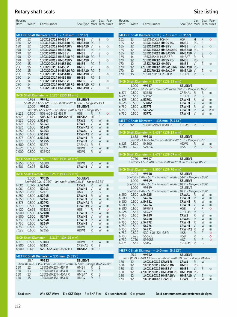
Seal tech: W = SKF Wave E = SKF Edge F = SKF Flex S = standard oil G = grease Bold part numbers are preferred designs
Rotary shaft seals Size listing
HousingBore Width
Part Number Seal Type
Lip Mat'l
Seal Tech
Fea-tures
METRIC Shaft Diameter (cont.) – 130 mm (5.118")
XX HMS V HMS V E ◎
XX HMSA RG HMSA RG E XX HMSA V HMSA V E ◎
XX HMS RG HMS RG E XX HMS V HMS V E ◎
XX HMSA RG HMSA RG E XX HMSA V HMSA V E ◎
XX HMS RG HMS RG E XX HMS V HMS V E ◎
XX HMSA RG HMSA RG E XX HMSA V HMSA V E ◎
XX HMS RG HMS RG E XX HMS V HMS V E ◎
XX HMSA RG HMSA RG E XX HMSA V HMSA V E ◎
INCH Shaft Diameter – 5.125" (130.18 mm)
. SSLEEVEShaft Ø.-." - 'on-shaft' width ." - flange Ø."
. SSLEEVEShaft Ø.-." - 'on-shaft' width ." - flange Ø."
. . -- HS R HS R F ◇
. . -- HDSH HT HDSH HT F. . ▲ CRW R W ■
. . CRW V W ■
. . CRWHA R W ■
. . CRWA V W ■
. . ▲ CRWHA R W ■
. . ▲ CRWH R W. . CRWH V W ■
. . CRSHA R S. . HDW R W ■
. . HDW R W
INCH Shaft Diameter – 5.188" (131.78 mm)
. . HDW R W ■
. . CRWH V W ■
INCH Shaft Diameter – 5.250" (133.35 mm)
. SSLEEVEShaft Ø.-." - 'on-shaft' width ." - flange Ø."
. . ▲ CRW R W ■
. . CRWH V W ■
. . HM R G. . ▲ CRWH R W ■
. . CRWH V W ■
. . ▲ CRWHA R W. . CRWHA V W ■
. . HS R F ◇
. . ▲ CRWH R W ■
. . CRWH V W ■
. . ▲ CRWH R W ■
. . CRWH V W ■
. . HDW R W ■
. . HDW R W ■
INCH Shaft Diameter – 5.313" ( 134.95 mm)
. . HDW R W ■
. . CRSHA R S. . -- HDSH HT HDSH HT F
METRIC Shaft Diameter – 135 mm (5.315")
. SSLEEVEShaft Ø.-.mm - 'on-shaft' width .mm - flange Ø.mm
XX HMS R HMS R S XX HMS R HMS R S XX HMSA R HMSA R S XX HMS R HMS R S
Housing Bore
Width
Part Number
Seal Type
Lip Mat'l
Seal Tech
Fea-tures
METRIC Shaft Diameter (cont.) – 135 mm (5.315")
XX HS H HS H F ◇
XX HMS RG HMS RG E XX HMS V HMS V E ◎
XX HMSA RG HMSA RG E XX HMSA V HMSA V E ◎
XX HMSA R HMSA R S XX HMS RG HMS RG E XX HMS V HMS V E ◎
▲ XX HMSA RG HMSA RG E XX HMSA V HMSA V E ◎
XX CRSH R CRSH R S
INCH Shaft Diameter – 5.375" (136.53 mm)
. SSLEEVEShaft Ø.-." - 'on-shaft' width ." - flange Ø."
. . CRSHA R S ■
. . CRSH R S. . ▲ CRWH R W ■
. . CRWH V W ■
. . ▲ CRWH R W ■
. . CRWH R W ◤◎
. . CRWH V W ■
METRIC Shaft Diameter – 138 mm (5.433")
XX CRSA R CRSA R S
INCH Shaft Diameter – 5.438" (138.13 mm)
. SSLEEVEShaft Ø.-." - 'on-shaft' width ." - flange Ø."
. . HDW R W ■
. . HS R F ◇
INCH Shaft Diameter – 5.476" (139.09 mm)
. SSLEEVEShaft Ø.-." - 'on-shaft' width ." - flange Ø."
INCH Shaft Diameter – 5.500" (139.70 mm)
. SSLEEVEShaft Ø.-." - 'on-shaft' width ." - flange Ø."
. SSLEEVEShaft Ø.-." - 'on-shaft' width ." - flange Ø."
. GSLEEVEShaft Ø.-." - 'on-shaft' width ." - flange Ø."
. . ▲ CRWA R W ■
. . CRWH P W ■
. . ▲ CRWH R W ■
. . CRWH V W ■
. . HS V F ◇
. . CRSHA R S. . CRW R W ■
. . CRWA R W ■
. . ▲ CRWH R W ■
. . CRWH V W ■
. . CRWHA R W ■
. . -- HS R HS R F ◇
. . HS R F ◇
. . HS R F ◇
. . CRSHA R S
METRIC Shaft Diameter – 140 mm (5.512")
. SSLEEVEShaft Ø.-.mm - 'on-shaft' width .mm - flange Ømm
XX CRW R CRW R W XX HMS RG HMS RG E XX HMS V HMS V E ◎
▲ XX HMSA RG HMSA RG E XX HMSA V HMSA V E ◎
XX CRW R CRW R W ■
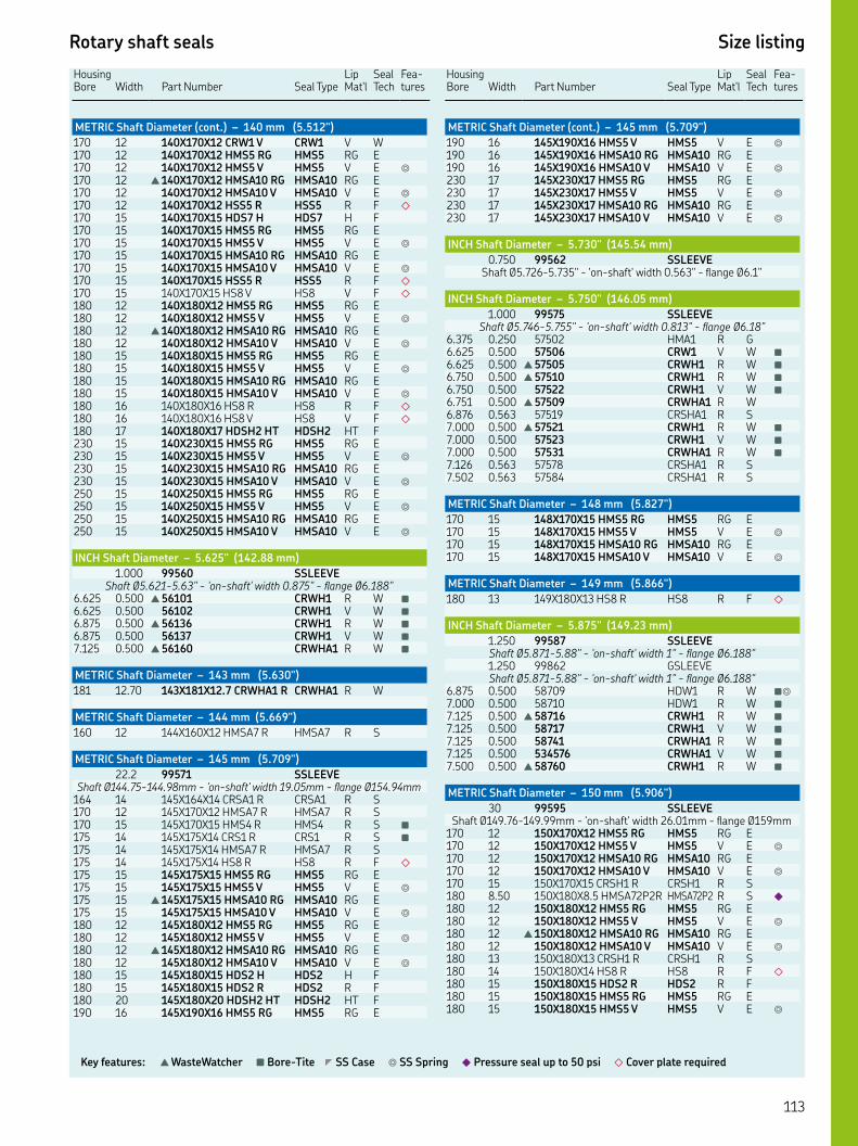
Rotary shaft seals Size listing
Key features: ▲ WasteWatcher ■ Bore-Tite ◤ SS Case ◎ SS Spring ◆ Pressure seal up to 50 psi ◇ Cover plate required
HousingBore Width
Part Number Seal Type
Lip Mat'l
Seal Tech
Fea-tures
METRIC Shaft Diameter (cont.) – 140 mm (5.512")
XX CRW V CRW V W XX HMS RG HMS RG E XX HMS V HMS V E ◎
▲ XX HMSA RG HMSA RG E XX HMSA V HMSA V E ◎
XX HSS R HSS R F ◇
XX HDS H HDS H F XX HMS RG HMS RG E XX HMS V HMS V E ◎
XX HMSA RG HMSA RG E XX HMSA V HMSA V E ◎
XX HSS R HSS R F ◇
XX HS V HS V F ◇
XX HMS RG HMS RG E XX HMS V HMS V E ◎
▲ XX HMSA RG HMSA RG E XX HMSA V HMSA V E ◎
XX HMS RG HMS RG E XX HMS V HMS V E ◎
XX HMSA RG HMSA RG E XX HMSA V HMSA V E ◎
XX HS R HS R F ◇
XX HS V HS V F ◇
XX HDSH HT HDSH HT F XX HMS RG HMS RG E XX HMS V HMS V E ◎
XX HMSA RG HMSA RG E XX HMSA V HMSA V E ◎
XX HMS RG HMS RG E XX HMS V HMS V E ◎
XX HMSA RG HMSA RG E XX HMSA V HMSA V E ◎
INCH Shaft Diameter – 5.625" (142.88 mm)
. SSLEEVEShaft Ø.-." - 'on-shaft' width ." - flange Ø."
. . ▲ CRWH R W ■
. . CRWH V W ■
. . ▲ CRWH R W ■
. . CRWH V W ■
. . ▲ CRWHA R W ■
METRIC Shaft Diameter – 143 mm (5.630")
. XX. CRWHA R CRWHA R W
METRIC Shaft Diameter – 144 mm (5.669")
XX HMSA R HMSA R S
METRIC Shaft Diameter – 145 mm (5.709")
. SSLEEVEShaft Ø.-.mm - 'on-shaft' width .mm - flange Ø.mm
XX CRSA R CRSA R S XX HMSA R HMSA R S XX HMS R HMS R S ■
XX CRS R CRS R S ■
XX HMSA R HMSA R S XX HS R HS R F ◇
XX HMS RG HMS RG E XX HMS V HMS V E ◎
▲ XX HMSA RG HMSA RG E XX HMSA V HMSA V E ◎
XX HMS RG HMS RG E XX HMS V HMS V E ◎
▲ XX HMSA RG HMSA RG E XX HMSA V HMSA V E ◎
XX HDS H HDS H F XX HDS R HDS R F XX HDSH HT HDSH HT F XX HMS RG HMS RG E
Housing Bore
Width
Part Number
Seal Type
Lip Mat'l
Seal Tech
Fea-tures
METRIC Shaft Diameter (cont.) – 145 mm (5.709")
XX HMS V HMS V E ◎
XX HMSA RG HMSA RG E XX HMSA V HMSA V E ◎
XX HMS RG HMS RG E XX HMS V HMS V E ◎
XX HMSA RG HMSA RG E XX HMSA V HMSA V E ◎
INCH Shaft Diameter – 5.730" (145.54 mm)
. SSLEEVEShaft Ø.-." - 'on-shaft' width ." - flange Ø."
INCH Shaft Diameter – 5.750" (146.05 mm)
. SSLEEVEShaft Ø.-." - 'on-shaft' width ." - flange Ø."
. . HMA R G. . CRW V W ■
. . ▲ CRWH R W ■
. . ▲ CRWH R W ■
. . CRWH V W ■
. . ▲ CRWHA R W. . CRSHA R S. . ▲ CRWH R W ■
. . CRWH V W ■
. . CRWHA R W ■
. . CRSHA R S. . CRSHA R S
METRIC Shaft Diameter – 148 mm (5.827")
XX HMS RG HMS RG E XX HMS V HMS V E ◎
XX HMSA RG HMSA RG E XX HMSA V HMSA V E ◎
METRIC Shaft Diameter – 149 mm (5.866")
XX HS R HS R F ◇
INCH Shaft Diameter – 5.875" (149.23 mm)
. SSLEEVEShaft Ø.-." - 'on-shaft' width " - flange Ø.". GSLEEVEShaft Ø.-." - 'on-shaft' width " - flange Ø."
. . HDW R W ■◎
. . HDW R W ■
. . ▲ CRWH R W ■
. . CRWH V W ■
. . CRWHA R W ■
. . CRWHA V W ■
. . ▲ CRWH R W ■
METRIC Shaft Diameter – 150 mm (5.906")
SSLEEVEShaft Ø.-.mm - 'on-shaft' width .mm - flange Ømm
XX HMS RG HMS RG E XX HMS V HMS V E ◎
XX HMSA RG HMSA RG E XX HMSA V HMSA V E ◎
XX CRSH R CRSH R S . XX. HMSAPR HMSAP R S ◆
XX HMS RG HMS RG E XX HMS V HMS V E ◎
▲ XX HMSA RG HMSA RG E XX HMSA V HMSA V E ◎
XX CRSH R CRSH R S XX HS R HS R F ◇
XX HDS R HDS R F XX HMS RG HMS RG E XX HMS V HMS V E ◎

Seal tech: W = SKF Wave E = SKF Edge F = SKF Flex S = standard oil G = grease Bold part numbers are preferred designs
Rotary shaft seals Size listing
HousingBore Width
Part Number Seal Type
Lip Mat'l
Lip Tech
Fea-tures
METRIC Shaft Diameter (cont.) – 150 mm (5.906")
XX HMSA RG HMSA RG E XX HMSA V HMSA V E ◎
XX HS V HS V F ◇
XX HDSF VT HDSF VT F ◤
XX HS R HS R F ◇
XX HDSF VT HDSF VT F XX HMS RG HMS RG E XX HMS V HMS V E ◎
XX HMSA RG HMSA RG E XX HMSA V HMSA V E ◎
XX HMS RG HMS RG E XX HMS V HMS V E ◎
XX HMSA RG HMSA RG E XX HMSA V HMSA V E ◎
INCH Shaft Diameter – 5.938" (150.83 mm)
. SSLEEVEShaft Ø.-." - 'on-shaft' width " - flange Ø."
. . HDW R W ■
METRIC Shaft Diameter – 151 mm (5.945")
XX HS R HS R F ◇
INCH Shaft Diameter – 6.000" (152.40 mm)
. SSLEEVEShaft Ø.-." - 'on-shaft' width " - flange Ø."
. . CRW V W ■
. . CRWA V W ■
. . HS R F ◇
. . -- HS R HS R F ◇
. . CRSHA R S ■
. . HS R F ■◇
. . ▲ CRWHA R W ■
. . CRWHA V W ■
. . HDW R W ■
. . HS R F ◇
. . HM R G. . CRWA R W ■
. . ▲ CRWHA R W ■
. . CRWHA V W ■
. . HS R F ◇
. . HDS R F
METRIC Shaft Diameter – 154 mm (6.063")
SSLEEVEShaft Ø.-.mm - 'on-shaft' width .mm - flange Ø.mm
CRSA R S XX CRSA R CRSA R S. . HDW R W ■
METRIC Shaft Diameter – 155 mm (6.102")
SSLEEVEShaft Ø.-.mm - 'on-shaft' width .mm - flange Ø.mm
XX HMS RG HMS RG E XX HMS V HMS V E ◎
▲ XX HMSA RG HMSA RG E XX HMSA V HMSA V E ◎
XX HMS RG HMS RG E XX HMS V HMS V E ◎
XX HMSA RG HMSA RG E XX HMSA V HMSA V E ◎
XX HMS R HMS R S XX HDS R HDS R F
INCH Shaft Diameter – 6.125" (155.58 mm)
. . HDW R W ■
. . ▲ CRWH R W. . HDW R W ■
Housing Bore
Width
Part Number
Seal Type
Lip Mat'l
Lip Tech
Fea-tures
INCH Shaft Diameter (cont.) – 6.125" (155.58 mm)
. . - HS R F ◇
. . HDW R W ■
. . -- HS V HS R F ◇
. . CRSHA R S. . CRWH P W. . ▲ CRWH R W. . -- HS R HS R F ◇
INCH Shaft Diameter – 6.188" (157.18 mm)
. . HS R F ◇
. . CRSH P S
INCH Shaft Diameter – 6.203" (157.56 mm)
. SSLEEVEShaft Ø.-." - 'on-shaft' width ." - flange Ø."
INCH Shaft Diameter – 6.250" (158.75 mm)
. SSLEEVEShaft Ø.-." - 'on-shaft' width ." - flange Ø."
. . HDW R W ■
. . -- HS V HS V F ◇
. . HS R F ◇
. . ▲ CRWH R W. . ▲ CRWH R W. . CRWH V W ■
. . ▲ CRWH R W ■
. . ▲ CRWH R W ■
METRIC Shaft Diameter – 160 mm (6.299")
. SSLEEVEShaft Ø.-.mm - 'on-shaft' width .mm - flange Ø.mm XX HMS R HMS R S XX CRSA V CRSA V S XX HMS RG HMS RG E XX HMS V HMS V E ◎
▲ XX HMSA RG HMSA RG E XX HMSA V HMSA V E ◎
XX CRW V CRW V W ■
XX HMS RG HMS RG E XX HMS V HMS V E ◎
▲ XX HMSA RG HMSA RG E XX HMSA V HMSA V E ◎
XX HDSH HT HDSH HT F XX HMSA R HMSA R S XX HDSH HT HDSH HT F XX HMS RG HMS RG E XX HMS V HMS V E ◎
XX HMSA RG HMSA RG E XX HMSA V HMSA V E ◎
INCH Shaft Diameter – 6.375" (161.93 mm)
. . ▲ CRWH R W ■
. . -- HDSH HT HDSH HT F. . HDW R W ■
. . ▲ CRWHA R W ■
. . CRWH R W
INCH Shaft Diameter – 6.438" ( 163.53 mm)
. . HDW R W ■
. . HS R F ◇
. . HS R F ◇
. . HS R F ◇
. . HS R F ◇
METRIC Shaft Diameter – 165 mm (6.496")
XX HMS R HMS R S XX HMS RG HMS RG E XX HMS V HMS V E ◎
Don’t s
ee t
he
size
you n
eed?
SK
F F
lex
seals
are
ava
ilable
fast
in c
ust
om
ized
siz
es a
nd m
ate
rials
wit
h N
O toolin
g c
harg
es.

Rotary shaft seals Size listing
Key features: ▲ WasteWatcher ■ Bore-Tite ◤ SS Case ◎ SS Spring ◆ Pressure seal up to 50 psi ◇ Cover plate required
HousingBore Width
Part Number Seal Type
Lip Mat'l
Lip Tech
Fea-tures
METRIC Shaft Diameter (cont.) – 165 mm (6.496")
▲ XX HMSA RG HMSA RG E XX HMSA V HMSA V E ◎
XX HMS RG HMS RG E XX HMS V HMS V E ◎
XX HMSA RG HMSA RG E XX HMSA V HMSA V E ◎
INCH Shaft Diameter – 6.500" (165.10 mm)
. SSLEEVEShaft Ø.-." - 'on-shaft' width " - flange Ø"
. . HS R F ◇
. . CRWA R W ■
. . ▲ CRWH R W. . CRWH V W ■
. . -- HSS R HSS R F ◇
. . HS V F ◇
. . HS R F ◇
. . HDS R F. . HS R F ◇
. . CRW R W ■
. . ▲ CRWHA R W. . CRWA V W ■
METRIC Shaft Diameter – 168 mm (6.614")
HS D F ◇
XX CRSH R CRSH R S
INCH Shaft Diameter – 6.625" (168.28 mm)
. . HS R F ◇
. . HDW R W ■
. . HDW R W ■
. . HDW R W ■
. . ▲ CRWH R W. . HDSA RD F
METRIC Shaft Diameter – 170 mm (6.693")
SSLEEVEShaft Ø.-mm - 'on-shaft' width .mm - flange Ø.mm
XX CRSH R CRSH R S XX HDS R HDS R F XX HDS V HDS V F XX HDS R HDS R F XX HMS RG HMS RG E XX HMS V HMS V E ◎
▲ XX HMSA RG HMSA RG E XX HMSA V HMSA V E ◎
XX HS R HS R F ◇
XX HS V HS V F ◇
XX HS V HS V F ◇
XX HDS D HDS D F XX HMSA R HMSA R S XX HDS R HDS R F XX HDS R HDS R F XX HDS V HDS V F
INCH Shaft Diameter – 6.750" (171.15 mm)
. SSLEEVEShaft Ø.-." - 'on-shaft' width ." - flange Ø."
. . HDW R W ■
. . HDS R F. . HDS V F. . ▲ CRWH R W ■
. . HS R F ◇
. . HS V F ◇
. . ▲ CRWH R W. . HS R F ◇
. . HDW R W ■
Housing Bore
Width
Part Number
Seal Type
Lip Mat'l
Lip Tech
Fea-tures
INCH Shaft Diameter – 6.875" (174.63 mm)
. . HS R F ◇
. . HDW R W ■
. . ▲ CRWH R W. . HDW R W ■
METRIC Shaft Diameter – 175 mm (6.890")
SSLEEVEShaft Ø.-.mm - 'on-shaft' width .mm - flange Ømm
XX HMS RG HMS RG E XX HMS V HMS V E ◎
XX HMSA RG HMSA RG E XX HMSA V HMSA V E ◎
XX HDS R HDS R F ◤
XX HDS V HDS V F XX HMS R HMS R S
INCH Shaft Diameter – 6.938" ( 176.23 mm)
. . HDS V F
INCH Shaft Diameter – 7.000" (176.80 mm)
. SSLEEVEShaft Ø.-." - 'on-shaft' width " - flange Ø."
. . HS D F ◇
. . HS R F ◇
. . HS V F ◇
. . ▲ CRWH R W ■
. . ▲ CRWH R W. . HDS R F. . -- HDS V HDS V F. . HS R F ◇
. . CRSHA R S. . HS R F ◇
. . CRWA R W ■
. . HS R F ◇
. . CRWH R W ■
. . ▲ CRWHA R W ■
. . CRWHA V W ■
. . HDS V F. . HDS R F. . HS R F ◇
. . HS R F ◇
METRIC Shaft Diameter – 178 mm (7.008")
XX HSSG H HSSG H F ◇
INCH Shaft Diameter – 7.025" (178.44 mm)
. . HDS V F
METRIC Shaft Diameter – 180 mm (7.087")
SSLEEVEShaft Ø.-.mm - 'on-shaft' width .mm - flange Ø.mm XX CRS R CRS R S XX HMS RG HMS RG E XX HMS V HMS V E ◎
XX HMSA RG HMSA RG E XX HMSA V HMSA V E ◎
XX HS R HS R F ◇
XX HDS H HDS H F XX HDS H HDS H F XX HMS RG HMS RG E XX HMS V HMS V E ◎
▲ XX HMSA RG HMSA RG E XX HMSA V HMSA V E ◎
XX HS V HS V F ◇
XX HDSH HT HDSH HT F XX HMS RG HMS RG E XX HMS V HMS V E ◎
XX HMSA RG HMSA RG E
Don’t see th
e size you n
eed? S
KF F
lex seals a
re availa
ble fa
st in cu
stom
ized sizes a
nd m
ateria
ls with
NO
toolin
g ch
arg
es.

Seal tech: W = SKF Wave E = SKF Edge F = SKF Flex S = standard oil G = grease Bold part numbers are preferred designs
Rotary shaft seals Size listing
HousingBore Width
Part Number Seal Type
Lip Mat'l
Lip Tech
Fea-tures
METRIC Shaft Diameter (cont.) – 180 mm (7.087")
XX HMSA V HMSA V E ◎
XX CRS R CRS R S XX HDS V HDS V F XX HDS V HDS V F XX HDS R HDS R F XX HDS H HDS H F XX HS V HS V F ◇
XX HDSH HT HDSH HT F XX HDS R HDS R F XX HS R HS R F ◇
INCH Shaft Diameter – 7.125" (180.98 mm)
. . HS R F ◇
. . HS R F ◇
. . HDS R F. . HDW R W ■
. . HDS R F. . ▲ CRWH R W
INCH Shaft Diameter – 7.188" (182.58 mm)
. . HDS R F. . HS R F ◇
. . HS R F ◇
INCH Shaft Diameter – 7.250" (184.15 mm)
. SSLEEVEShaft Ø.-." - 'on-shaft' width ." - flange Ø."
. . HS R F ◇
. . HS R F ◇
. . ▲ CRW R W. . -- HDS R HDS R F. . HDS R F. . HDS V F. . ▲ CRWHA R W ■
. . HDS H F ■
. . HDS V F. . HDS R F. . HDS V F. . HS R F ◇
. . CRWH P W. . HDSA VD F. . ▲ CRWHA R W ■
METRIC Shaft Diameter – 185 mm (7.283")
SSLEEVEShaft Ø.-.mm - 'on-shaft' width mm - flange Ø.mm
XX HMS RG HMS RG E XX HMS V HMS V E ◎
XX HMSA RG HMSA RG E XX HMSA V HMSA V E ◎
XX HS R HS R F ◇
. . HDS R F XX HDS V HDS V F
METRIC Shaft Diameter – 186 mm (7.323")
XX HS R HS R F ◇
INCH Shaft Diameter – 7.375" (187.33 mm)
. . HDW R W ■
. . HDW R W ■
. . HDSH VT F. . ▲ CRWH R W
METRIC Shaft Diameter – 188 mm (7.402")
XX CRWH R CRWH R W ■
Housing Bore
Width
Part Number
Seal Type
Lip Mat'l
Lip Tech
Fea-tures
INCH Shaft Diameter – 7.438" ( 188.93 mm)
. . HS R F ◇
. . HS V F ◇
METRIC Shaft Diameter – 189 mm (7.441")
XX HS V HS V F ◇
INCH Shaft Diameter – 7.449" (189.20 mm)
. SSLEEVEShaft Ø.-." - 'on-shaft' width ." - flange Ø."
METRIC Shaft Diameter – 190 mm (7.480")
XX HSS V HSS V F ◇
XX CRSH R CRSH R S XX HMS RG HMS RG E XX HMS V HMS V E ◎
▲ XX HMSA RG HMSA RG E XX HMSA V HMSA V E ◎
XX HS R HS R F ◇
XX HDS V HDS V F XX HDS D HDS D F XX HDS H HDS H F XX HMS RG HMS RG E XX HMS V HMS V E ◎
▲ XX HMSA RG HMSA RG E XX HMSA V HMSA V E ◎
XX HS R HS R F ◇
XX HS V HS V F ◇
XX HS R HS R F ◇
XX HMS RG HMS RG E XX HMS V HMS V E ◎
XX HMSA RG HMSA RG E XX HMSA V HMSA V E ◎
XX HDS R HDS R F XX HS R HS R F ◇
INCH Shaft Diameter – 7.500" (190.50 mm)
. SSLEEVEShaft Ø.-." - 'on-shaft' width ." - flange Ø."
. . HS R F ◇
. . ▲ CRWH R W. . HS R F ◇
. . HS R F ◇
. . HDW R W ■
. . HDS V F. . HS D F ◇
. . HS R F ◇
. . ▲ CRWH R W ■
. . CRWHA P W ■
. . HDS V F. . -- HDSH HT HDSH HT F. . HDS V F. . HDSA RD F. . HDSA VD F. . -- HDSH HT HDSH HT F. . HDW R W ■
. . HDS V F. . -- HDSH HT HDSH HT F
INCH Shaft Diameter – 7.625" (193.68 mm)
. . ▲ CRWH R W. . HDW R W ■
. . HS R F ◇
. . HS R F ◇
. . ▲ CRWH R W
METRIC Shaft Diameter – 195 mm (7.677")
XX CRSH R CRSH R S XX HDS R HDS R F
Don’t s
ee t
he
size
you n
eed?
SK
F F
lex
seals
are
ava
ilable
fast
in c
ust
om
ized
siz
es a
nd m
ate
rials
wit
h N
O toolin
g c
harg
es.

Rotary shaft seals Size listing
Key features: ▲ WasteWatcher ■ Bore-Tite ◤ SS Case ◎ SS Spring ◆ Pressure seal up to 50 psi ◇ Cover plate required
HousingBore Width
Part Number Seal Type
Lip Mat'l
Lip Tech
Fea-tures
METRIC Shaft Diameter (cont.) – 195 mm (7.677")
XX HDSH RT HDSH RT F
INCH Shaft Diameter – 7.750" (196.85 mm)
. SSLEEVEShaft Ø.-." - 'on-shaft' width " - flange Ø."
. . HDW R W ■
. . HS R F ◇
. . HS D F ◇
. . HDS R F. . HDS V F. . HS R F ◇
. . ▲ CRWH R W. . HDS V F. . HDS D F. . HDS R F. . HDS V F
INCH Shaft Diameter – 7.800" (198.12 mm)
. . HDS R F
METRIC Shaft Diameter – 199 mm (7.835")
XX HDS R HDS R F
INCH Shaft Diameter – 7.835" (199.01 mm)
. . HDS V F
METRIC Shaft Diameter – 200 mm (7.835)"
. SSLEEVEShaft Ø.-.mm - 'on-shaft' width .mm - flange Ø.mm XX HMSAP R HMSAP R S ◆
XX HDS V HDS V F XX HDS V HDS V F XX HDS V HDS V F XX HDS H HDS H F XX HDS R HDS R F XX HDS V HDS V F XX HMS RG HMS RG E XX HMS V HMS V E ◎
▲ XX HMSA RG HMSA RG E XX HMSA V HMSA V E ◎
HS R F ◇
XX HS R HS R F ◇
XX HS V HS V F ◇
. XX. HDS R HDS R F XX HDS D HDS D F
W/LIGHT LOAD SPRING XX HDSF VT HDSF VT F ◤
XX HS V HS V F ◇
XX HMSA R HMSA R S XX HDS R HDS R F XX HS R HS R F ◇
XX HS R HS R F ◇
XX HDS V HDS V F XX HS R HS R F ◇
XX HMS RG HMS RG E XX HMS V HMS V E ◎
▲ XX HMSA RG HMSA RG E XX HMSA V HMSA V E ◎
XX HDS H HDS H F XX HDS V HDS V F XX HDS R HDS R F . XX. HDS V HDS V F . XX. HDS V HDS V F XX HDS R HDS R F XX HDS R HDS R F XX HS V HS V F ◇
XX HDS R HDS R F XX HMS RG HMS RG E
Housing Bore
Width
Part Number
Seal Type
Lip Mat'l
Lip Tech
Fea-tures
METRIC Shaft Diameter (cont.) – 200 mm (7.835")
XX HMS V HMS V E ◎
XX HMSA RG HMSA RG E XX HMSA V HMSA V E ◎
INCH Shaft Diameter – 7.875" (200.03 mm)
. SSLEEVEShaft Ø.-." - 'on-shaft' width ." - flange Ø."
. . HDW R W ■
. . HS R F ◇
. . ▲ CRWHA R W. . ▲ CRWH R W. . HDS D F. . HDS V F. . HDS V F. . HDS V F. . HDS R F
INCH Shaft Diameter – 7.938" (201.63 mm)
. SSLEEVEShaft Ø.-." - 'on-shaft' width " - flange Ø."
. . HM R G. . HDW R W ■
. . HS R F ◇
. . HS R F ◇
. . HDS R F. . HDS V F
INCH Shaft Diameter – 8.000" (203.20 mm)
. SSLEEVEShaft Ø.-." - 'on-shaft' width " - flange Ø."
. . HS V F ◇
. . ▲ CRWH R W. . CRWHA R W. . HDS R F. . -- HSS R HSS R F ◇
. . HS V F ◇
. . ▲ CRWH R W. . CRWHA R W ■
. . HDS V F. . HDS R F. . HS R F ◇
. . HS V F ◇
. . HDS R F. . ▲ CRWH R W ■
. . HDS H F. . HS R F ◇
. . HDS V F. . HDS V F. . ▲ CRWHA R W. . HDS R F. . HS R F ◇
. . HDS R F. . HDSL R F. . HS R F ◇
. . HDS D F. . HDSA RD F. . HDSA RD F. . HDS R F. . HDS V F. . HDSA RD F. . HDSA RD F. . HDSA RD F. . HDSA RD F
METRIC Shaft Diameter – 205 mm (8.071")
XX HDS V HDS V F
Don’t see th
e size you n
eed? S
KF F
lex seals a
re availa
ble fa
st in cu
stom
ized sizes a
nd m
ateria
ls with
NO
toolin
g ch
arg
es.
199 mm

Seal tech: W = SKF Wave E = SKF Edge F = SKF Flex S = standard oil G = grease Bold part numbers are preferred designs
Rotary shaft seals Size listing
HousingBore Width
Part Number Seal Type
Lip Mat'l
Lip Tech
Fea-tures
INCH Shaft Diameter – 8.125" (206.38 mm)
. . HS V F ◇
. . HDS R F. . ▲ CRWH R W. . CRWHA R W. . HDS R F. . HDS V F. . HDS R F. . HDS R F
INCH Shaft Diameter – 8.188" (207.98 mm)
. . HDS R F
INCH Shaft Diameter – 8.250" (209.55 mm)
. . ▲ CRWH R W. . ▲ CRWH R W ■
. . HS R F ◇
. . ▲ CRW R W. . HDS R F. . HDS D F. . HDS R F
W/LIGHT LOAD SPRING. . HDS R F. . HDS V F. . HS R F ◇
. . HS R F ◇
. . HS V F ◇
. . -- HDS R HDS R F. . HS R F ◇
. . HDS R F. . HDS R F. . HDS R F. . -- HS R HS R F ◇
. . ▲ CRWH R W. . HDS V F. . HDS R F. . HDS V F. . HDS D F. . HS R F ◇
. . HS R F ◇
. . HDS V F. . HDS R F. . HDS R F. . HDS R F
METRIC Shaft Diameter – 210 mm (8.268")
XX HDS V HDS V F XX HMS RG HMS RG E XX HMS V HMS V E ◎
▲ XX HMSA RG HMSA RG E XX HMSA V HMSA V E ◎
XX HS R HS R F ◇
XX HDS R HDS R F XX HDS D HDS D F XX HDSH DT HDSH DT F XX HDS R HDS R F XX HDS V HDS V F XX HDS V HDS V F XX HDS V HDS V F XX HMS R HMS R S XX HS R HS R F ◇
XX HSS V HSS V F ◇
XX HDS R HDS R F XX HDS R HDS R F XX HDS V HDS V F XX HDS R HDS R F XX HS V HS V F ◇
XX HDS D HDS D F XX HDS R HDS R F XX HDS V HDS V F
Housing Bore
Width
Part Number
Seal Type
Lip Mat'l
Lip Tech
Fea-tures
METRIC Shaft Diameter (cont.) – 210 mm (8.268")
XX HDS V HDS V F XX HMS RG HMS RG E XX HMS V HMS V E ◎
XX HMSA RG HMSA RG E XX HMSA V HMSA V E ◎
INCH Shaft Diameter – 8.345" (211.96 mm)
. . HDS V F. . HDS R F. . HDS R F. . HDS R F. . HS R F ◇
. . HDS R F. . HDS R F. . HDS R F. . HDS R F
INCH Shaft Diameter – 8.438" (214.33 mm)
. . HDS R F. . HDS V F
METRIC Shaft Diameter – 215 mm (8.465")
XX HDS R HDS R F XX HDS H HDS H F XX HDS H HDS H F . XX. HDSA RD HDSA RD F XX HDS R HDS R F
INCH Shaft Diameter – 8.500" (215.90 mm)
. . HDS R F. . HS R F ◇
. . HS V F ◇
. . HS V F ◇
. . ▲ CRWH R W ■
. . HDS R F. . -- HDS V HDS V F. . HDS D F. . -- HDS H HDS H F. . HDS R F. . HDS V F. . HDS D F. . HDS R F. . HDS R F. . HS V F ◇
. . HS R F ◇
. . HS V F ◇
. . ▲ CRWH R W. . CRWH R W. . HDS R F. . HDSL R F. . HDS R F. . HDS V F. . -- HS R HS R F ◇
. . HDS V F. . HDSA RD F. . HS R F ◇
. . ▲ CRWH R W. . CRWH V W. . HDS V F. . HDS V F. . HS R F ◇
. . HS R F ◇
. . HDSL R F. . HDSA VD F. . HDSA RD F. . HDS R F. . ▲ CRWHA R W
Don’t s
ee t
he
size
you n
eed?
SK
F F
lex
seals
are
ava
ilable
fast
in c
ust
om
ized
siz
es a
nd m
ate
rials
wit
h N
O toolin
g c
harg
es.
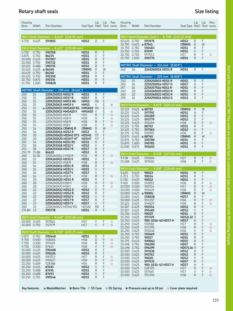
Rotary shaft seals Size listing
Key features: ▲ WasteWatcher ■ Bore-Tite ◤ SS Case ◎ SS Spring ◆ Pressure seal up to 50 psi ◇ Cover plate required
HousingBore Width
Part Number Seal Type
Lip Mat'l
Lip Tech
Fea-tures
INCH Shaft Diameter – 8.540" (216.92 mm)
. . HDS D F
INCH Shaft Diameter – 8.625" (219.08 mm)
. . HDS R F. . HDS V F. . HDS R F. . HDS R F. . HDS R F. . ▲ CRWH R W. . HDS V F. . HDS R F. . HDS R F. . HDS R F
METRIC Shaft Diameter – 220 mm (8.661")
XX HDS R HDS R F XX HDS R HDS R F XX HMS RG HMS RG E XX HMS V HMS V E ◎
▲ XX HMSA RG HMSA RG E XX HMSA V HMSA V E ◎
XX HS R HS R F ◇
XX HS H HS H F ◇
XX HS R HS R F ◇
XX HS V HS V F ◇
XX CRWH R CRWH R W XX HDS R HDS R F XX HDSH DT HDSH DT F XX HDSH HT HDSH HT F XX HDS R HDS R F XX HDS V HDS V F XX HDS R HDS R F. . HDS R F . XX. HS R HS R F ◇
XX HDS V HDS V F XX HS R HS R F ◇
XX HDS R HDS R F XX HDS V HDS V F XX HDS V HDS V F XX HS R HS R F ◇
XX HDS R HDS R F XX HS H HS H F ◇
XX HS V HS V F ◇
XX HDS D HDS D F XX HDS R HDS R F XX HDS V HDS V F XX HDS R HDS R F XX HDS V HDS V F XX HDSA RD HDSA RD F. HDS R F
INCH Shaft Diameter – 8.668" (220.68 mm)
. . HS V F ◇
. . HS V F ◇
INCH Shaft Diameter – 8.750" (222.25 mm)
. . HDS R F. . HS D F ◇
. . HS R F ◇
. . HS V F ◇
. . HDS R F. . HDS R F. . HS R F ◇
. . HS R F ◇
. . HS R F ◇
. . HDS V F. . HDS R F. . HDS V F. . HDS R F
Housing Bore
Width
Part Number
Seal Type
Lip Mat'l
Lip Tech
Fea-tures
INCH Shaft Diameter (cont.) – 8.750" (222.25 mm)
. . HDS R F. . ▲ CRWH R W. . HDS R F. . HDS V F. . HS R F ◇
. . HDS R F
METRIC Shaft Diameter – 224 mm (8.819")
XX HDS R HDS R F
METRIC Shaft Diameter – 225 mm (8.858")
XX HDS R HDS R F XX HDS H HDS H F XX HDS R HDS R F XX HDS R HDS R F XX HDS R HDS R F XX HDS D HDS D F
INCH Shaft Diameter – 8.875" (225.43 mm)
. . ▲ CRWH R W. . HDS H F. . HDS R F. . HDS D F. . HS R F ◇
. . HDS R F. . HDS H F. . HS R F ◇
. . ▲ CRWH R W. . HDS R F. . HDS R F. . HDS R F
INCH Shaft Diameter – 8.938" (227.03 mm)
. . HS R F ◇
. . HS R F ◇
INCH Shaft Diameter – 9.000" (228.60 mm)
. . HDS R F. . HDS R F. . HDS V F. . HS R F ◇
. . HS R F ◇
. . HS R F ◇
. . ▲ CRWH R W. . HDS R F. . HS R F ◇
. . HS R F ◇
. . HDS R F. . HDS V F. . HDS R F. . HDSL D F. . -- HDS H HDS H F. . HS R F ◇
. . HS R F ◇
. . HS V F ◇
. . HDS D F. . HDS R F. . HDS R F. . HDS R F. . HDSL R F. . HDS D F. . HDS R F. . HDS V F. . HDS R F. . -- HDS H HDS H F. . HS R F ◇
. . HS V F ◇
. . HS R F ◇
Don’t see th
e size you n
eed? S
KF F
lex seals a
re availa
ble fa
st in cu
stom
ized sizes a
nd m
ateria
ls with
NO
toolin
g ch
arg
es.
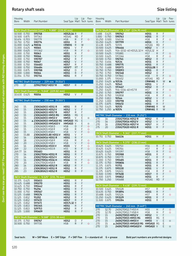
Seal tech: W = SKF Wave E = SKF Edge F = SKF Flex S = standard oil G = grease Bold part numbers are preferred designs
Rotary shaft seals Size listing
HousingBore Width
Part Number Seal Type
Lip Mat'l
Lip Tech
Fea-tures
INCH Shaft Diameter (cont.) – 9.000" (228.60 mm)
. . HDSL R F. . HDSA RD F. . HS R F ◇
. . HDS R F. . ▲ CRWH R W. . HDS V F. . HS R F ◇
. . HDS R F. . HDS V F. . HDS R F. . HDS V F. . HDS R F. . HDSF RT F. . HDS D F. . HDS R F. . HDS R F
METRIC Shaft Diameter – 229 mm (9.016")
XX HDS R HDS R F
INCH Shaft Diameter – 9.048" (229.82 mm)
. . HDS V F
METRIC Shaft Diameter – 230 mm (9.055")
XX HDS R HDS R F XX HDS V HDS V F XX HDS R HDS R F XX HMS RG HMS RG E XX HMS V HMS V E ◎
▲ XX HMSA RG HMSA RG E XX HMSA V HMSA V E ◎
XX HS D HS D F ◇
XX HS R HS R F ◇
XX HS V HS V F ◇
. XX. HDS V HDS V F XX HDS R HDS R F XX HS R HS R F ◇
XX HS V HS V F ◇
XX HSS V HSS V F ◇
XX HS R HS R F ◇
. HDS R F XX HDS R HDS R F XX HDS V HDS V F XX HSS H HSS H F ◇
XX HS R HS R F ◇
XX HDS R HDS R F XX HDS R HDS R F XX HDS R HDS R F
INCH Shaft Diameter – 9.125" (231.78 mm)
. . HDS R F. . HDS R F. . HDS R F. . HDS R F. . HDS R F. . HDS R F. . HDS R F. . HDS R F. . HDSL R F. . HDS R F. . HDS R F. . HDS R F
INCH Shaft Diameter – 9.188" (233.38 mm)
. . HDS D F. . HS R F ◇
Housing Bore
Width
Part Number
Seal Type
Lip Mat'l
Lip Tech
Fea-tures
INCH Shaft Diameter – 9.250" (234.95 mm)
. . HDS R F. . HDS R F. . HS R F ◇
. . HDS R F. . HDSA RD F. . HDS V F. . -- HDSL H HDSL H F. . HS R F ◇
. . HS R F ◇
. . HDS R F. . HDS R F. . HDS R F. . HDSL R F. . HDS R F. . HDS D F. . HS R F ◇
. . HDSA RD F. . ▲ CRWHA R W ■
. . HDS V F. . HDS R F. . -- HS R HS R F ◇
. . HDS R F. . HS R F ◇
. . HDS V F. . HDS R F. . HDS R F. . CRWHA R W. . ▲ CRWHA R W
METRIC Shaft Diameter – 235 mm (9.252")
XX HDS R HDS R F XX HDS V HDS V F XX HDS H HDS H F XX HDS R HDS R F
INCH Shaft Diameter – 9.361" (237.77 mm)
. . HDS H F
INCH Shaft Diameter – 9.375" (238.13 mm)
. . HS R F ◇
. . HS R F ◇
. . HS R F ◇
. . HDS R F. . HS R F ◇
. . HDS R F. . HDS R F. . HDS R F. . HDS V F. . HS R F ◇
. . HDS R F. . HDS R F. . HDSA RD F
INCH Shaft Diameter – 9.438" (239.73 mm)
. . HS R F ◇
. . HDS R F. . HS R F ◇
. . HDS R F. . HDS R F
METRIC Shaft Diameter – 240 mm (9.449")
. XX. HS H HS H F ◇
. XX. HS H HS H F ◇
XX HDS V HDS V F XX HMS RG HMS RG E XX HMS V HMS V E ◎
▲ XX HMSA RG HMSA RG E XX HMSA V HMSA V E ◎
Don’t s
ee t
he
size
you n
eed?
SK
F F
lex
seals
are
ava
ilable
fast
in c
ust
om
ized
siz
es a
nd m
ate
rials
wit
h N
O toolin
g c
harg
es.

Rotary shaft seals Size listing
Key features: ▲ WasteWatcher ■ Bore-Tite ◤ SS Case ◎ SS Spring ◆ Pressure seal up to 50 psi ◇ Cover plate required
HousingBore Width
Part Number Seal Type
Lip Mat'l
Lip Tech
Fea-tures
METRIC Shaft Diameter (cont.) – 240 mm (9.449")
XX HS R HS R F ◇
XX HS V HS V F ◇
XX HDS R HDS R F XX HDS V HDS V F XX HDS D HDS D F XX HDS R HDS R F XX HDS R HDS R F XX HDS V HDS V F XX HDS V HDS V F XX HS R HS R F ◇
XX HDS R HDS R F XX HDS D HDS D F XX HMSA V HMSA V S XX HDS R HDS R F XX HSS H HSS H F ◇
XX HSS H HSS H F ◇
XX HS R HS R F ◇
XX HS V HS V F ◇
XX HS V HS V F ◇
XX HDS V HDS V F XX HDS D HDS D F XX HDS R HDS R F XX HSS H HSS H F ◇
XX HS V HS V F ◇
XX HDS H HDS H F XX HS H HS H F ◇
XX HDS V HDS V F XX HDS R HDS R F XX HS V HS V F ◇
XX HDS R HDS R F XX HS R HS R F ◇
XX HDS R HDS R F XX HDS R HDS R F. HDS R F XX HDS R HDS R F
INCH Shaft Diameter – 9.500" (241.30 mm)
. . ▲ CRW R W ■◤◎
. . HS D F ◇
. . HS R F ◇
W/HOOK & EYE SPRING CONNECTOR . . HS R F ◇
. . HM R G. . HDS R F. . HDS D F. . HDS R F. . HDS V F. . HS R F ◇
. . HS R F ◇
. . HDS R F. . HDSL R F. . HDS R F. . HDS H F. . HS R F ◇
. . HDS V F. . HDS R F. . HDSA RD F. . HDSA VD F. . HDS R F. . HDS R F. . ▲ CRW R W ■
. . HDS R F. . HDS D F. . -- HSS V HSS V F ◇
. . HS R F ◇
. . HDS R F. . HDS V F. . HDS V F. . -- HDS H HDS H F. . HS R F ◇
Housing Bore
Width
Part Number
Seal Type
Lip Mat'l
Lip Tech
Fea-tures
INCH Shaft Diameter (cont.) – 9.500" (241.30 mm)
. . HDS R F. . HDS R F. . HDS R F. . HDSL R F. . HDS R F. . HS R F ◇
. . HDSA DD F. . HDSA RD F
INCH Shaft Diameter – 9.563" (242.90 mm)
. . HS D F ◇
. . HS R F ◇
. . HDS R F
INCH Shaft Diameter – 9.620" (244.35 mm)
. . HDS R F. . HDSA RD F
INCH Shaft Diameter – 9.625" (244.48 mm)
. . HDS R F. . HDS R F. . HDS R F. . ▲ CRWH R W. . HDS V F. . HDS V F
METRIC Shaft Diameter – 245 mm (9.646")
XX HMS RG HMS RG E XX HMS V HMS V E ◎
XX HMSA RG HMSA RG E XX HMSA V HMSA V E ◎
INCH Shaft Diameter – 9.688" (246.08 mm)
. . HDS R F. . HDS R F. . HDS V F
INCH Shaft Diameter – 9.750" (247.65 mm)
. . HS R F ◇
. . HS R F ◇
. . HS R F ◇
. . HDS R F. . HDS V F. . HDS R F. . HDS V F. . HDSL R F. . HDS R F ■
. . HS R F ◇
. . HS R F ◇
. . HDS R F. . HDSA RD F. . ▲ CRWH R W. . HDS R F. . HDS R F. . ▲ CRWH R W. . HDS R F. . HS R F ◇
. . HS R F ◇
. . HDS R F. . HS R F ◇
. . HS R F ◇
. . HDSA DD F. . ▲ CRWH R W. . HDS V F. . HDS R F. . HDS R F. . HDS V F. . HDSA DD F
Don’t see th
e size you n
eed? S
KF F
lex seals a
re availa
ble fa
st in cu
stom
ized sizes a
nd m
ateria
ls with
NO
toolin
g ch
arg
es.
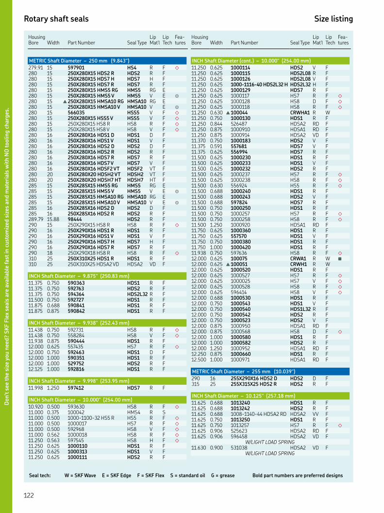
Seal tech: W = SKF Wave E = SKF Edge F = SKF Flex S = standard oil G = grease Bold part numbers are preferred designs
Rotary shaft seals Size listing
HousingBore Width
Part Number Seal Type
Lip Mat'l
Lip Tech
Fea-tures
METRIC Shaft Diameter – 250 mm (9.843")
. HS R F ◇
XX HDS R HDS R F XX HDS H HDS H F XX HDS R HDS R F XX HMS RG HMS RG E XX HMS V HMS V E ◎
▲ XX HMSA RG HMSA RG E XX HMSA V HMSA V E ◎
HSS V F ◇
XX HSS V HSS V F ◇
XX HS R HS R F ◇
XX HS V HS V F ◇
XX HDS D HDS D F XX HDS V HDS V F XX HDS D HDS D F XX HDS R HDS R F XX HDS R HDS R F XX HDS V HDS V F XX HDSF VT HDSF VT F XX HDSH VT HDSH VT F XX HDSH HT HDSH HT F XX HMS RG HMS RG E XX HMS V HMS V E ◎
XX HMSA RG HMSA RG E XX HMSA V HMSA V E ◎
XX HDS D HDS D F XX HDS R HDS R F. . HDS R F XX HS R HS R F ◇
XX HDS R HDS R F XX HDS V HDS V F XX HDS H HDS H F XX HDS R HDS R F XX HS R HS R F ◇
XX HDS R HDS R F XX HDSA VD HDSA VD F
INCH Shaft Diameter – 9.875" (250.83 mm)
. . HDS R F. . HDS R F. . HDSL R F. . HDS R F. . HDS R F. . HDS R F
INCH Shaft Diameter – 9.938" (252.43 mm)
. . HS R F ◇
. . HS V F ◇
. . HDS R F. . HS R F ◇
. . HDS D F. . HDS R F. . HDS R F. . HDS R F
INCH Shaft Diameter – 9.998" (253.95 mm)
. . HDS R F
INCH Shaft Diameter – 10.000" (254.00 mm)
. . HS R F ◇
. . HMS R S. . -- HS R HS R F ◇
. . HS R F ◇
. . HS V F ◇
. . HS R F ◇
. . HS H F ◇
. . HDS R F. . HDS V F. . HDS R F
Housing Bore
Width
Part Number
Seal Type
Lip Mat'l
Lip Tech
Fea-tures
INCH Shaft Diameter (cont.) – 10.000" (254.00 mm)
. . HDS V F. . HDSL R F. . HDSL V F. . -- HDSL H HDSL H F. . HDS R F. . HS R F ◇
. . HS D F ◇
. . HS R F ◇
. . ▲ CRWHA R W. . HDS R F. . HDSA RD F. . HDSA RD F. . HDSA VD F. . HDS V F. . HDS V F. . HDS R F. . HDS R F. . HDS V F. . HDS R F. . HS R F ◇
. . HS R F ◇
. . HS R F ◇
. . HDS R F. . HDS V F. . HDS R F. . HDS R F. . HS R F ◇
. . HS R F ◇
. . HDSA RD F. . HDS R F. . HDS V F. . HDS R F. . HDS R F. . HS R F ◇
. . CRWA R W ■
. . ▲ CRWH R W. . HDS R F. . HS R F ◇
. . HS V F ◇
. . HS R F ◇
. . HS V F ◇
. . HDS R F. . HDS V F. . HDSL R F. . HDS R F. . HDS V F. . HDSA RD F. . HS D F ◇
. . HDS R F. . HDS R F. . HDSA RD F. . HDS R F. . HDSA RD F
METRIC Shaft Diameter – 255 mm (10.039")
XX HDS D HDS D F XX HDS R HDS R F
INCH Shaft Diameter – 10.125" (257.18 mm)
. . HDS R F. . HDS R F. . -- HDSA RD HDSA VV F. . HDS R F. . HS R F ◇
. . HDSA RD F. . HDSA VD F
W/LIGHT LOAD SPRING. . HDSA VD F
W/LIGHT LOAD SPRING
Don’t s
ee t
he
size
you n
eed?
SK
F F
lex
seals
are
ava
ilable
fast
in c
ust
om
ized
siz
es a
nd m
ate
rials
wit
h N
O toolin
g c
harg
es.

Rotary shaft seals Size listing
Key features: ▲ WasteWatcher ■ Bore-Tite ◤ SS Case ◎ SS Spring ◆ Pressure seal up to 50 psi ◇ Cover plate required
HousingBore Width
Part Number Seal Type
Lip Mat'l
Lip Tech
Fea-tures
INCH Shaft Diameter (cont.) – 10.125" (257.18 mm)
. . HDS R F. . HDS R F. . HDS R F
INCH Shaft Diameter – 10.188" (258.78 mm)
. . HS R F ◇
. . HDS R F
INCH Shaft Diameter – 10.220" (259.59 mm)
. . HDS R F
METRIC Shaft Diameter – 260 mm (10.236")
. XX. HS R HS R F ◇
. HDS H F XX HDS H HDS H F XX HDS D HDS D F XX HDS H HDS H F XX HDS R HDS R F XX HDS V HDS V F XX HDS R HDS R F XX HDS V HDS V F XX HDSF VT HDSF VT F XX HDSF VT HDSF VT F XX HSS H HSS H F ◇
XX HSS H HSS H F ◇
XX HS R HS R F ◇
XX HS V HS V F ◇
XX HDS V HDS V F . HDS H F XX HDS V HDS V F XX HDS R HDS R F XX HS R HS R F ◇
XX HDS V HDS V F XX HDS R HDS R F XX HDS V HDS V F XX HDSL R HDSL R F XX HDS R HDS R F XX HS V HS V F ◇
XX HS V HS V F ◇
XX HDS R HDS R F XX HDS V HDS V F XX HDS D HDS D F XX HDS R HDS R F XX HDS V HDS V F XX CRS R CRS R S XX HS V HS V F ■◇
XX HS R HS R F ◇
XX HS V HS V F ◇
XX HDS R HDS R F XX HS R HS R F ◇
XX HDS R HDS R F XX HDS R HDS R F. HDS R F XX HDS V HDS V F ■
XX HDS R HDS R F XX HDSA RD HDSA RD F
INCH Shaft Diameter – 10.250" (260.35 mm)
. . CRWH R W. . HS R F ◇
. . HS V F ◇
. . HDS D F. . HS R F ◇
. . HS R F ◇
. . HS R F ◇
. . HDS R F. . HDS V F. . HDS R F
Housing Bore
Width
Part Number
Seal Type
Lip Mat'l
Lip Tech
Fea-tures
INCH Shaft Diameter (cont.) – 10.250" (260.35 mm)
. . HDS R F. . HDS R F. . HS R F ◇
. . ▲ CRWH R W. . HDS R F. . HS R F ◇
. . HDS R F. . HDS V F. . HDS R F. . HDS R F. . HDS D F. . HDS R F. . HDS R F. . HDS R F
INCH Shaft Diameter – 10.375" (263.53 mm)
. . HDS R F. . HDS V F. . HDS D F. . HDS R F. . HDSA DD F. . HDS R F. . HDS D F
INCH Shaft Diameter – 10.420" (264.67 mm)
. . HS R F ◇
INCH Shaft Diameter – 10.422" ( 264.72 mm)
. . -- HDS R HDS R F
METRIC Shaft Diameter – 265 mm (10.433")
XX HDS R HDS R F XX HDS R HDS R F XX HDS R HDS R F
INCH Shaft Diameter – 10.438" (265.13 mm)
. . HDS R F. . HS R F ◇
. . HDS R F. . HDS R F
METRIC Shaft Diameter – 266 mm (10.472")
XX HS R HS R F ◇
INCH Shaft Diameter – 10.495" (266.57 mm)
. . HDS H F
INCH Shaft Diameter – 10.500" (266.70 mm)
. . HS R F ◇
. . HS R F ◇
. . HS R F ◇
. . HS V F ◇
. . HS R F ◇
. . ▲ CRWH R W. . HDS R F. . HDS V F. . HDS R F. . HS R F ◇
. . HS V F ◇
. . HS R F ◇
. . HS V F ◇
. . HDS R F. . HS R F ◇
. . HDS R F. . HDS R F. . HDS V F. . HDS H F
Don’t see th
e size you n
eed? S
KF F
lex seals a
re availa
ble fa
st in cu
stom
ized sizes a
nd m
ateria
ls with
NO
toolin
g ch
arg
es.

Seal tech: W = SKF Wave E = SKF Edge F = SKF Flex S = standard oil G = grease Bold part numbers are preferred designs
Rotary shaft seals Size listing
HousingBore Width
Part Number Seal Type
Lip Mat'l
Lip Tech
Fea-tures
INCH Shaft Diameter (cont.) – 10.500" (266.70 mm)
. . HDSL H F. . HDS R F. . HDS V F. . HDS D F. . HDS R F. . HDS V F. . HDSL R F. . HS R F ◇
. . HS R F ◇
. . HDS D F. . HDS R F. . HDS R F. . ▲ CRWH R W. . HDS R F. . HDS R F. . HDS V F. . HS R F ◇
. . HDS R F. . HDS R F. . HDS V F. . -- HDSL R HDSL R F. . HS D F ◇
. . HDS R F. . HDS D F. . HDS R F. . HDS R F. . HDSF VT F. . HDSA RD F. . HDS R F
METRIC Shaft Diameter – 267 mm (10.512")
XX HDS R HDS R F XX HDS R HDS R F
INCH Shaft Diameter – 10.625" (269.88 mm)
. . HDS R F. . HS R F ◇
. . HS R F ◇
. . HDS R F. . HDS R F. . HDS R F. . HDS R F. . HDS R F
METRIC Shaft Diameter – 270 mm (10.630")
XX HDS V HDS V F XX HS R HS R F ◇
XX HDS R HDS R F XX HDS V HDS V F XX HDS R HDS R F XX HDS V HDS V F XX HDS H HDS H F XX HDSF VT HDSF VT F XX HDS R HDS R F XX HDS V HDS V F XX HDSH VT HDSH VT F XX HDSH HT HDSH HT F. HDS R F XX HSS V HSS V F ◇
XX HDS R HDS R F XX HDS R HDS R F XX HDS V HDS V F XX HDS R HDS R F XX HDS V HDS V F XX HDS R HDS R F
INCH Shaft Diameter – 10.688" (271.48 mm)
. . HDS V F. . -- HDS V HDS V F
Housing Bore
Width
Part Number
Seal Type
Lip Mat'l
Lip Tech
Fea-tures
INCH Shaft Diameter (cont.) – 10.688" (271.48 mm)
. . HDS V F
INCH Shaft Diameter – 10.710" (272.03 mm)
. . HS R F ◇
INCH Shaft Diameter – 10.750" (273.05 mm)
. . HS R F ◇
. . HDS R F. . HDS R F. . HDS R F. . HDS V F. . HDSL R F. . HS R F ◇
. . HS D F ◇
. . HS R F ◇
. . HS V F ◇
. . HS R F ◇
. . HDS R FSPECIAL CASE FOR VRING SURFACE
. . HDS R F. . HS R F ◇
. . HS R F ◇
. . HDS R F. . HDSA RD F. . HDS R F. . HDS V F. . HDS H F. . -- HDS V HDS RD F. . HDSL R F. . HDSL V F. . HDSA RD F. . HDSA VD F. . HDSA RD F. . HDSA VD F
W/LIGHT LOAD SPRING. . HDSA RD F. . HDS R F. . ▲ CRWH R W. . HDS R F. . HDS V F. . HDS R F. . HDS H F. . HDS V F. . HDSF RT F ◎
. . HDS R F. . HDS R F. . HDS R F. . HDS R F. . HDS V F. . HDS R F
METRIC Shaft Diameter – 275 mm (10.827")
HDS V F XX HDS R HDS R F XX HDS R HDS R F XX HDS R HDS R F
INCH Shaft Diameter – 10.875" (276.23 mm)
. . HS R F ◇
. . HS R F ◇
. . HS R F ◇
INCH Shaft Diameter – 10.938" (277.83 mm)
. . HDS R F. . HDS R F. . HDS V F
METRIC Shaft Diameter – 275 mm (10.827")
XX HS R HS R F ◇
Don’t s
ee t
he
size
you n
eed?
SK
F F
lex
seals
are
ava
ilable
fast
in c
ust
om
ized
siz
es a
nd m
ate
rials
wit
h N
O toolin
g c
harg
es.
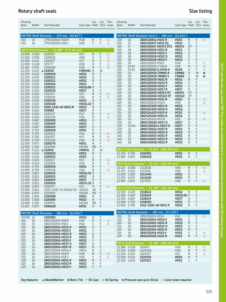
Rotary shaft seals Size listing
Key features: ▲ WasteWatcher ■ Bore-Tite ◤ SS Case ◎ SS Spring ◆ Pressure seal up to 50 psi ◇ Cover plate required
HousingBore Width
Part Number Seal Type
Lip Mat'l
Lip Tech
Fea-tures
METRIC Shaft Diameter – 275 mm (10.827")
XX HS R HS R F ◇
XX HS V HS V F ◇
INCH Shaft Diameter – 11.000" (279.40 mm)
. . HS R F ◇
. . HS H F ◇
. . HS R F ◇
. . HS R F ◇
. . HS R F ◇
. . ▲ CRWHA R W. . HDS R F. . HDS D F. . HDS R F. . HDS V F. . HDSL R F. . HDS R F. . HS R F ◇
. . HS R F ◇
. . HDS R F. . HDSL R F. . -- HDS R HDS R F. . HDS R F. . HS R F ◇
. . HS R F ◇
. . HDS H F. . HDS V F. . HDS H F. . HDS R F. . HS R F ◇
. . HS R F ◇
. . HS R F ◇
. . HDS R F. . HDSA RD F. . ▲ CRWH R W. . HDS R F. . HDS V F. . HS R F ◇
. . HS R F ◇
. . HDS R F. . HS R F ◇
. . HDSL R F. . HDS R F. . HDS R F. . HDSL R F. . HS R F ◇
. . -- HDSA VD HDSA VD F. . HDSA RD F. . HDS R F. . HDS R F. . HDSA RD F. . HDS R F
METRIC Shaft Diameter – 280 mm (11.024")
. HDS D F XX HS R HS R F ◇
XX HS V HS V F ◇
XX HDS R HDS R F XX HDS V HDS V F XX HDS D HDS D F XX HDS R HDS R F XX HDS V HDS V F XX HDS H HDS H F XX HDS R HDS R F XX HMS R HMS R S XX HS R HS R F ◇
XX HS V HS V F ◇
XX HDS R HDS R F XX HDS R HDS R F XX HDS V HDS V F
Housing Bore
Width
Part Number
Seal Type
Lip Mat'l
Lip Tech
Fea-tures
METRIC Shaft Diameter (cont.) – 280 mm (11.024")
XX HSS R HSS R F ◇
XX HDS D HDS D F XX HDSF DT HDSF DT F XX HDS R HDS R F XX HDS V HDS V F XX HDS D HDS D F XX HDS V HDS V F XX HS V HS V F ◇
. XX. HS R HS R F ◇
. XX. HSS H HSS H F ◇
XX CRWA R CRWA R W ■
XX CRWA V CRWA V W ■
XX HDS R HDS R F XX HDS R HDS R F XX HDS V HDS V F XX HDS R HDS R F XX HDSF DT HDSF DT F XX HDSH DT HDSH DT F XX HSS R HSS R F ◇
XX HS R HS R F ◇
XX HDS R HDS R F XX HDS D HDS D F XX HSS H HSS H F ◇
XX HDS R HDS R F XX HS R HS R F ◇
XX HDS D HDS D F . XX. HDS D HDS D F XX HDS R HDS R F XX HDS R HDS R F XX HDS R HDS R F XX HDS R HDS R F XX HDS R HDS R F
INCH Shaft Diameter – 11.063" (281.00 mm)
. . HDS R F. . HDS R F
INCH Shaft Diameter – 11.125" (282.58 mm)
. . HS R F ◇
. . HS R F ◇
. . HDS R F. . HDS R F. . HS V F ◇
INCH Shaft Diameter – 11.188" (284.18 mm)
. . HDS R F. . HDSL H F. . HDS H F. . HDS R F. . -- HDS R HDS R F
METRIC Shaft Diameter – 285 mm (11.220")
XX HS V HS V F ◇
XX HDS V HDS V F XX HDS R HDS R F XX HDS H HDS H F XX HDS R HDS R F XX HSS V HSS V F ◇
XX HSS R HSS R F ◇
INCH Shaft Diameter – 11.188" (284.18 mm)
. . HS R F ◇
. . HS R F ◇
. . HS R F ◇
. . HDS R F. . HDS V F
Don’t see th
e size you n
eed? S
KF F
lex seals a
re availa
ble fa
st in cu
stom
ized sizes a
nd m
ateria
ls with
NO
toolin
g ch
arg
es.
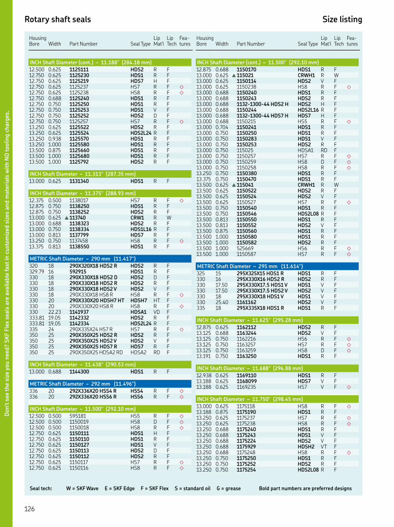
Seal tech: W = SKF Wave E = SKF Edge F = SKF Flex S = standard oil G = grease Bold part numbers are preferred designs
Rotary shaft seals Size listing
HousingBore Width
Part Number Seal Type
Lip Mat'l
Lip Tech
Fea-tures
INCH Shaft Diameter (cont.) – 11.188" (284.18 mm)
. . HDS R F. . HDS R F. . HDS H F. . HS R F ◇
. . HS R F ◇
. . HDS R F. . HDS R F. . HDS V F. . HDS D F. . HS R F ◇
. . HDS R F. . HDSL R F. . HDS R F. . HDS R F. . HDS R F. . HDS R F. . HDS R F
INCH Shaft Diameter – 11.313" (287.35 mm)
. . HDS R F
INCH Shaft Diameter – 11.375" (288.93 mm)
. . HS R F ◇
. . HDS R F. . HDS R F. . ▲ CRW R W. . HDS R F. . HDSL R F. . HDS R F. . HS R F ◇
. . HDS R F
METRIC Shaft Diameter – 290 mm (11.417")
XX HDS R HDS R F. HDS R F XX HDS D HDS D F XX HDS R HDS R F XX HDS V HDS V F XX HS R HS R F ◇
XX HDSH HT HDSH HT F XX HS R HS R F ◇
. HDSA VD F. . HDS R F. . HDSL R F XX HS R HS R F ◇
XX HDS R HDS R F XX HDS V HDS V F XX HDS R HDS R F XX HDSA RD HDSA RD F
INCH Shaft Diameter – 11.438" (290.53 mm)
. . HDS R F
METRIC Shaft Diameter – 292 mm (11.496")
XX HSS R HSS R F ◇
XX HSS R HSS R F ◇
INCH Shaft Diameter – 11.500" (292.10 mm)
. . HS R F ◇
. . HS D F ◇
. . HS R F ◇
. . HDS H F. . HDS R F. . HDS V F. . HDS D F. . HDS R F. . HS R F ◇
. . HS R F ◇
Housing Bore
Width
Part Number
Seal Type
Lip Mat'l
Lip Tech
Fea-tures
INCH Shaft Diameter (cont.) – 11.500" (292.10 mm)
. . HDS R F. . ▲ CRWH R W. . HDS V F. . HS R F ◇
. . HDS R F. . HDS R F. . -- HDS H HDS H F. . HDSL R F. . -- HDS H HDS H F. . HS R F ◇
. . HDS R F. . HDS R F. . HDS V F. . HDS R F. . HDSA RD F. . HS R F ◇
. . HS D F ◇
. . HS R F ◇
. . HDS R F. . HDS R F. . ▲ CRWH R W. . HDS R F. . HDS V F. . HS R F ◇
. . HDS R F. . HDSL R F. . HDS R F. . HDS V F. . HDS R F. . HDS R F. . HDS R F. . HS R F ◇
. . HS R F ◇
METRIC Shaft Diameter – 295 mm (11.614")
XX HDS R HDS R F XX HDS R HDS R F . XX. HDS V HDS V F . XX. HDS V HDS V F XX HDS V HDS V F . HDS V F XX HDS R HDS R F
INCH Shaft Diameter – 11.625" (295.28 mm)
. . HDS R F. . HDS V F. . HS R F ◇
. . HS R F ◇
. . HS D F ◇
. . HDS R F
INCH Shaft Diameter – 11.688" (296.88 mm)
. . HDS R F. . HDS V F. . HS V F ◇
INCH Shaft Diameter – 11.750" (298.45 mm)
. . HS R F ◇
. . HDS R F. . HS R F ◇
. . HS R F ◇
. . HDS R F. . HDS V F. . HDS V F. . HDSH VT F. . HS R F ◇
. . HDS R F. . HDS R F. . HDSL R F
Don’t s
ee t
he
size
you n
eed?
SK
F F
lex
seals
are
ava
ilable
fast
in c
ust
om
ized
siz
es a
nd m
ate
rials
wit
h N
O toolin
g c
harg
es.

Rotary shaft seals Size listing
Key features: ▲ WasteWatcher ■ Bore-Tite ◤ SS Case ◎ SS Spring ◆ Pressure seal up to 50 psi ◇ Cover plate required
HousingBore Width
Part Number Seal Type
Lip Mat'l
Lip Tech
Fea-tures
INCH Shaft Diameter (cont.) – 11.750" (298.45 mm)
. . HDSL V F. . HS R F ◇
. . HS V F ◇
. . HDSA RD F. . HDSA VD F. . HDSA RD F. . HDS R F. . HS R F ◇
. . HDS R F. . HDSL R F. . HDS R F. . HDS V F. . HDS R F. . HDSA RD F. . HDS R F
METRIC Shaft Diameter – 300 mm (11.811")
XX HS R HS R F ◇
XX HS R HS R F ◇
XX HDS R HDS R F XX HDS V HDS V F XX HDS R HDS R F. . HDS R F. . HS R F ◇
. HDS R F . XX. HS R HS R F ◇
XX HDS R HDS R F XX HDS V HDS V F XX HDS V HDS V F XX HSS H HSS H F ◇
XX HMS R HMS R S XX HMSA R HMSA R S XX HDS D HDS D F XX HDS V HDS V F XX HDS R HDS R F XX HDS V HDS V F XX HDS R HDS R F XX HMS R HMS R S XX HS R HS R F ◇
XX HS V HS V F ◇
XX HDS D HDS D F XX HDS R HDS R F XX HDS V HDS V F XX HDS R HDS R F XX HDS V HDS V F XX HDS R HDS R F XX HSS H HSS H F ◇
XX HS V HS V F ◇
HS R F ◇
XX HS R HS R F ◇
XX HS V HS V F ◇
XX HDS V HDS V F XX HDS V HDS V F XX HDS V HDS V F XX HDS R HDS R F XX HS V HS V F ◇
XX HDS R HDS R F XX HS R HS R F ◇
XX HDSF HT HDSF HT F XX HDS R HDS R F HDS R F XX HDS R HDS R F XX HDSF VT HDSF VT F XX HDS R HDS R F XX HDS V HDS V F XX HDSA VD HDSA VD F
INCH Shaft Diameter – 11.813" (300.05 m)
. . HS R F ■◇
Housing Bore
Width
Part Number
Seal Type
Lip Mat'l
Lip Tech
Fea-tures
INCH Shaft Diameter (cont.) – 11.813" (300.05 mm)
. . HDS R F. . HS R F ◇
. . HDS R F. . HDSL R F. . HDS R F
INCH Shaft Diameter – 11.875" (301.63 mm)
. . HS R F ◇
INCH Shaft Diameter – 11.938" (303.23 mm)
. . HS R F ◇
INCH Shaft Diameter – 12.000" (304.80 mm)
. . HD D G. . HS R F ◇
. . HS R F ◇
. . HS D F ◇
. . HS R F ◇
. . HS R F ◇
. . HDS R F. . HS R F ◇
. . HS R F ◇
. . HS H F ◇
. . HS R F ◇
. . HDS R F. . HDS V F. . HS R F ◇
. . HDS V F. . HDS R F. . HDS V F. . HDS R F. . HDSL R F. . HDS R F. . HDSL R F. . HS R F ◇
. . HS R F ◇
. . HDS R F. . HDS R F. . HDS R F. . HS V F ◇
. . HS R F ◇
. . HDSH RT F ◤
. . HS R F ◇
. . HDSA RD F. . HDS D F. . HDS R F. . HDS R F. . HS R F ◇
. . HDS R F. . HDS R F. . ▲ CRW R W. . HDS R F. . HDS V F. . HDS V F. . HS R F ◇
. . HDS R F. . HDS V F. . HDS R F. . HDS R F. . HDSL R F. . HS H F ◇
. . HDS R F. . HDSH HT F. . HDS R F. . HDS R F. . HS R F ◇
. . HDSA RD F. . HDSA VD F. . HDS R F
Don’t see th
e size you n
eed? S
KF F
lex seals a
re availa
ble fa
st in cu
stom
ized sizes a
nd m
ateria
ls with
NO
toolin
g ch
arg
es.

Seal tech: W = SKF Wave E = SKF Edge F = SKF Flex S = standard oil G = grease Bold part numbers are preferred designs
Rotary shaft seals Size listing
HousingBore Width
Part Number Seal Type
Lip Mat'l
Lip Tech
Fea-tures
INCH Shaft Diameter (cont.) – 12.000" (304.80 mm)
. . HDS R F. . HDS V F. . HDS R F. . HDSA RD F. . HDS R F. . HDS R F. . HDS R F
INCH Shaft Diameter – 12.125" (307.98 mm)
. . HS R F ◇
. . HS H F ◇
. . HS R F ◇
. . HDS R F. . HDS R F. . HDS R F
INCH Shaft Diameter – 12.188" (309.58 mm)
. . HDS D F
METRIC Shaft Diameter – 310 mm (12.205")
XX HS R HS R F ◇
XX HS V HS V F ◇
XX HDS V HDS V F XX HS R HS R F ◇
XX HS R HS R F ◇
XX HDS R HDS R F XX HDS V HDS V F XX HDS R HDS R F XX HS R HS R F ◇
XX HDS D HDS D F XX HDS R HDS R F XX HS D HS D F ◇
XX HS R HS R F ◇
XX HS V HS V F ◇
XX HDS R HDS R F XX HDS D HDS D F XX HDS R HDS R F XX HDS V HDS V F
INCH Shaft Diameter – 12.250" (311.15 mm)
. . ▲ CRWH R W. . HS R F ◇
. . HDS R F. . HDS V F. . HDSL D F. . HS R F ◇
. . HDS R F. . HDS V F. . HDS D F. . HDSL R F. . HDS R F. . HDS R F. . HDS D F. . HS R F ◇
. . HDS H F. . HDSA RD F. . ▲ CRW R W. . HDS V F. . HDS R F. . HDS D F. . HDS R F. . HDS R F. . HDS R F ■
. . HDS R F. . HDS R F. . HDS R F. . HDS V F. . HS R F ◇
. . HS R F ◇
Housing Bore
Width
Part Number
Seal Type
Lip Mat'l
Lip Tech
Fea-tures
INCH Shaft Diameter (cont.) – 12.250" (311.15 mm)
. . HDS R F. . HDS R F. . HDS R F. . HDSA RD F. . HDS R F
INCH Shaft Diameter – 12.283" (311.99 mm)
. . HDS D F
METRIC Shaft Diameter – 314 mm (12.362")
XX HSS R HSS R F ◇
INCH Shaft Diameter – 12.373" (314.27 mm)
. . HDS D F
INCH Shaft Diameter – 12.375" (314.33 mm)
. . HS R F ◇
. . HDS R F. . HDS R F. . HS R F ◇
METRIC Shaft Diameter – 315 mm (12.402")
XX HS R HS R F ◇
XX HDS V HDS V F XX HS V HS V F ◇
XX HS V HS V F ◇
XX HDS R HDS R F XX HDS V HDS V F XX HDS H HDS H F. X.X HDS R HDS R F XX HDS R HDS R F XX HDSF VT HDSF VT F XX HDSH VT HDSH VT F
INCH Shaft Diameter – 12.438" (315.93 mm)
. . HS R F ◇
INCH Shaft Diameter – 12.438" (315.93 mm)
. . HS R F ◇
. . HS R F ◇
. . HDS R F. . HDS V F. . HDS V F. . HS R F ◇
. . HDS R F. . HDSA RD F. . HS R F ◇
. . HDS R F. . HS R F ◇
. . HDS R F. . HDS R F. . HDS R F. . HS D F ◇
. . HDS R F. . HDS R F. . HS R F ◇
. . HS R F ◇
. . HDS R F. . HDSA RD F. . HDSA VD F. . HDS V F. . HDS R F. . HDS V F. . HDS R F. . HDS R F. . HDS R F. . HS H F ◇
. . HDS R F
Don’t s
ee t
he
size
you n
eed?
SK
F F
lex
seals
are
ava
ilable
fast
in c
ust
om
ized
siz
es a
nd m
ate
rials
wit
h N
O toolin
g c
harg
es.

Rotary shaft seals Size listing
Key features: ▲ WasteWatcher ■ Bore-Tite ◤ SS Case ◎ SS Spring ◆ Pressure seal up to 50 psi ◇ Cover plate required
HousingBore Width
Part Number Seal Type
Lip Mat'l
Lip Tech
Fea-tures
INCH Shaft Diameter (cont.) – 12.438" (315.93 mm)
. . HDS V F. . HDSL R F. . HDS R F. . HDS R F. . HDS R F. . HS R F ◇
. . HDSA RD F. . HDS R F. . HDS R F. . HDS R F
METRIC Shaft Diameter – 318 mm (12.520")
XX HDS R HDS R F XX HDS R HDS R F
INCH Shaft Diameter – 12.565" (319.15 mm)
. . HDS R F
METRIC Shaft Diameter – 320 mm (12.598")
XX HDS R HDS R F XX HDS R HDS R F XX HDS H HDS H F XX HDS R HDS R F XX HDS R HDS R F XX HDS R HDS R F XX HDS R HDS R F XX HDS V HDS V F XX HDS H HDS H F XX HDS R HDS R F XX HDS H HDS H F XX HDS R HDS R F XX HDS V HDS V F XX HDS D HDS D F XX HSS H HSS H F ◇
XX HSS H HSS H F ◇
XX HSS H HSS H F ◇
XX HDS R HDS R F XX HDS V HDS V F XX HDS V HDS V F XX HDS R HDS R F XX HDSF VT HDSF VT F XX HDSH VT HDSH VT F XX HDSH HT HDSH HT F XX HSS H HSS H F ◇
XX HSS H HSS H F ◇
XX HS R HS R F ◇
XX HS H HS H F ◇
XX HS R HS R F ◇
XX HS V HS V F ◇
XX HDS H HDS H F XX HSS H HSS H F ◇
XX HDSA VD HDSA VD F XX HDS R HDS R F XX HDS V HDS V F XX HDS D HDS D F XX HDS R HDS R F XX HDS V HDS V F XX HS R HS R F ◇
XX HDS R HDS R F XX HDS R HDS R F XX HDS R HDS R F XX HDSA RD HDSA RD F
INCH Shaft Diameter – 12.625" (320.68 mm)
. . HS R F ◇
. . HDS D F. . HS R F ◇
. . HDS R F. . HDSL R F ■
Housing Bore
Width
Part Number
Seal Type
Lip Mat'l
Lip Tech
Fea-tures
INCH Shaft Diameter (cont.) – 12.625" (320.68 mm)
. . HDS R F. . HDS R F. . HDS R F
INCH Shaft Diameter – 12.688" (322.28 mm)
. . HS R F ◇
. . HDS R F. . HDSF VT F. . HDSH VT F. . HDS R F
INCH Shaft Diameter – 12.750" (323.85 mm)
. . HMSA R S. . HDS H F. . HS R F ◇
. . HDS R F. . HDS R F. . HDS V F. . HDSL V F. . HDS R F. . HDS R F. . HS V F ◇
. . HS R F ◇
. . HS R F ◇
. . HDS V F. . -- HDSH RT HDSH RT F. . HDS R F. . HDS R F. . HDS R F. . HDS R F
METRIC Shaft Diameter – 325 mm 325 mm (12.795")
XX HDS R HDS R F XX HDS R HDS R F XX HDS R HDS R F XX HDSH HT HDSH HT F XX HS R HS R F ◇
XX HS R HS R F ◇
XX HDS H HDS H F XX HDS R HDS R F
INCH Shaft Diameter – 12.875" (327.03 mm)
. . HDS R F. . HS R F ◇
. . HDS R F. . HDS R F. . HDSL D F
METRIC Shaft Diameter – 330 mm (12.992")
XX HS R HS R F ◇
XX HDS R HDS R F XX HDS R HDS R F XX HDS R HDS R F ◤
XX HDS D HDS D F XX HDS R HDS R F XX HDS V HDS V F XX HS V HS V F ◇
XX HS R HS R F ◇
XX HDS R HDS R F XX HDS V HDS V F XX HDS V HDS V F XX HDSL R HDSL R F XX HDSF VT HDSF VT F XX HDSH VT HDSH VT F XX HS R HS R F ◇
XX HDSF HT HDSF HT F XX HDS R HDS R F XX HDSL H HDSL H F
Don’t see th
e size you n
eed? S
KF F
lex seals a
re availa
ble fa
st in cu
stom
ized sizes a
nd m
ateria
ls with
NO
toolin
g ch
arg
es.

Seal tech: W = SKF Wave E = SKF Edge F = SKF Flex S = standard oil G = grease Bold part numbers are preferred designs
Rotary shaft seals Size listing
HousingBore Width
Part Number Seal Type
Lip Mat'l
Lip Tech
Fea-tures
METRIC Shaft Diameter (cont.) – 330 mm (12.992")
XX HDS V HDS V F XX HDS V HDS V F XX HS D HS D F ◇
XX HDS R HDS R F ◤
XX HSS H HSS H F ◇
XX HS R HS R F ◇
XX HS H HS H F ◇
XX HDS R HDS R F XX HDS D HDS D F XX HDS R HDS R F
INCH Shaft Diameter – 13.000" (330.20 mm)
. . HS D F ◇
. . HS R F ◇
. . HS H F ◇
. . -- HS V HS V F ◇
. . HS R F ◇
. . HS R F ◇
. . HS V F ◇
. . HDS R F. . HDS R F. . HDS V F. . HDS H F ◤
. . HDS R F. . HDS V F. . -- HDS H HDS H F. . -- HDS H HDS V F. . HDS D F. . HDS R F. . HDS R F. . HS R F ◇
. . HS D F ◇
. . HS R F ◇
. . HDSH HT F ◤
. . HDSA RD F. . HDS R F. . HDSA RD F. . HS R F ◇
. . HDS R F. . HDS R F. . HSS H F ◇
. . HS R F ◇
. . HDS R F. . HDS R F. . HSS H F ◇
. . HS R F ◇
. . HS R F ◇
. . HS R F ◇
. . HDS R F. . HDS V F. . HDS R F. . HDS R F. . HDS V F. . HDS R F
INCH Shaft Diameter – 13.125" (333.38 mm)
. . HDS R F. . HS R F ◇
INCH Shaft Diameter – 13.187" (334.95 mm)
. . HDS R F
INCH Shaft Diameter – 13.188" (334.98 mm)
. . -- HDS V HDS V F. . HDS R F
METRIC Shaft Diameter – 335 mm (13.189")
XX HDS R HDS R F XX HDS V HDS V F
Housing Bore
Width
Part Number
Seal Type
Lip Mat'l
Lip Tech
Fea-tures
INCH Shaft Diameter – 13.250" (336.55 mm)
. . -- HDS R HDS R F. . HS R F ◇
. . HDS R F. . HDS V F. . HDS D F. . HS R F ◇
. . HS R F ◇
. . HDS R F. . HDS R F. . HDS V F. . HDSL R F. . HDS R F. . HDS R F. . HDSA RD F. . HDSA VD F. . HDSA VD F. . HDS R F. . HDS R F. . HDS R F. . HDSA DD F. . HDS R F. . HDS R F. . HDS R F. . HDS R F. . HS D F ◇
. . HDS R F. . HDS R F. . HDS R F. . HDS R F. . HDS R F. . HDSF RT F. . HDS R F. . HDS V F. . HS R F ◇
. . HS R F ◇
. . HDS R F. . HDS R F. . HDS R F. . HDSL R F
METRIC Shaft Diameter – 340 mm (13.386")
XX HDS V HDS V F XX HDS R HDS R F XX HDS V HDS V F XX HDS R HDS R F XX HDS V HDS V F XX HS R HS R F ◇
XX HDS R HDS R F XX HDS V HDS V F XX HDS D HDS D F XX HDS R HDS R F XX HDS V HDS V F XX HS R HS R F ◇
XX HS V HS V F ◇
XX HDS R HDS R F XX HDS H HDS H F XX HDS R HDS R F XX HDS V HDS V F XX HDS R HDS R F XX HDSF VT HDSF VT F XX HDSH VT HDSH VT F XX HS R HS R F ◇
XX HS V HS V F ◇
XX HDSA HD HDSA HD F XX HDSA VD HDSA VD F XX HDS R HDS R F XX HS R HS R F ◇
XX HDS R HDS R F . XX. HDS R HDS R F. HDS R F
Don’t s
ee t
he
size
you n
eed?
SK
F F
lex
seals
are
ava
ilable
fast
in c
ust
om
ized
siz
es a
nd m
ate
rials
wit
h N
O toolin
g c
harg
es.
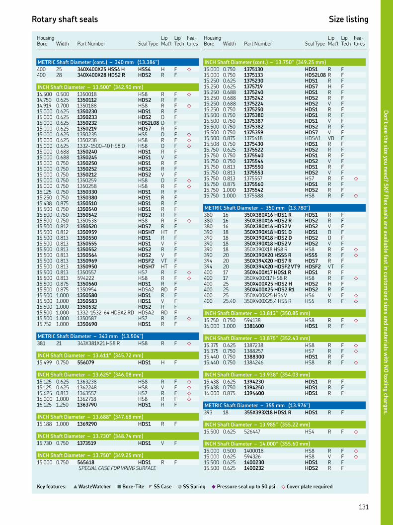
Rotary shaft seals Size listing
Key features: ▲ WasteWatcher ■ Bore-Tite ◤ SS Case ◎ SS Spring ◆ Pressure seal up to 50 psi ◇ Cover plate required
HousingBore Width
Part Number Seal Type
Lip Mat'l
Lip Tech
Fea-tures
METRIC Shaft Diameter (cont.) – 340 mm (13.386")
XX HSS H HSS H F ◇
XX HDS R HDS R F
INCH Shaft Diameter – 13.500" (342.90 mm)
. . HS R F ◇
. . HDS R F. . HS R F ◇
. . HDS R F. . HDS D F. . HDSL D F. . HDS R F. . HS D F ◇
. . HS R F ◇
. . -- HS D HS D F ◇
. . HDS R F. . HDS V F. . HDS R F. . HDS R F. . HDS V F. . HS D F ◇
. . HS R F ◇
. . HDS R F. . HDS R F. . HDS R F. . HDS R F. . HDS R F. . HS R F ◇
. . HDS R F. . HDSH HT F. . HDS R F. . HDS V F. . HDS R F. . HDS V F. . HDSF VT F. . HDSH HT F. . HS R F ◇
. . HS R F ◇
. . HDS R F. . HDSA RD F. . HDS R F. . HDS V F. . HDS R F. . -- HDSA RD HDSA RD F. . HS R F ◇
. . HDS R F
METRIC Shaft Diameter – 343 mm (13.504")
XX HS R HS R F ◇
INCH Shaft Diameter – 13.611" (345.72 mm)
. . HDS H F
INCH Shaft Diameter – 13.625" (346.08 mm)
. . HS R F ◇
. . HS V F ◇
. . HS R F ◇
. . HS R F ◇
. . HDS R F
INCH Shaft Diameter – 13.688" (347.68 mm)
. . HDS R F
INCH Shaft Diameter – 13.730" (348.74 mm)
. . HDS V F
INCH Shaft Diameter – 13.750" (349.25 mm)
. . HDS R FSPECIAL CASE FOR VRING SURFACE
Housing Bore
Width
Part Number
Seal Type
Lip Mat'l
Lip Tech
Fea-tures
INCH Shaft Diameter (cont.) – 13.750" (349.25 mm)
. . HDS R F. . HDSL R F. . HDS R F. . HDS H F. . HDS R F. . HDS R F. . HDS V F. . HDS R F. . HDS R F. . HDS V F. . HDS R F. . HDS V F. . HDSA VD F. . HDS R F. . HDS R F. . HDS R F. . HDS V F. . HDS R F. . HDS V F. . HS R F ◇
. . HDS R F. . HDS R F. . HS R F ◇
METRIC Shaft Diameter – 350 mm (13.780")
XX HDS R HDS R F XX HDS R HDS R F XX HDS V HDS V F XX HDS D HDS D F XX HDS D HDS D F XX HDS V HDS V F XX HS R HS R F ◇
XX HSS R HSS R F ◇
XX HDS R HDS R F XX HDSF VT HDSF VT F XX HDS R HDS R F XX HS R HS R F ◇
XX HDS H HDS H F XX HDS R HDS R F XX HS V HS V F ◇
. XX. HS R HS R F ◇
INCH Shaft Diameter – 13.813" (350.85 mm)
. . HS R F ◇
. . HDS R F
INCH Shaft Diameter – 13.875" (352.43 mm)
. . HS R F ◇
. . HS R F ◇
. . HDS R F. . HS R F ◇
INCH Shaft Diameter – 13.938" (354.03 mm)
. . HDS R F. . HDS R F. . HDS R F
METRIC Shaft Diameter – 355 mm (13.976")
XX HDS R HDS R F
INCH Shaft Diameter – 13.985" (355.22 mm)
. . HS R F ◇
INCH Shaft Diameter – 14.000" (355.60 mm)
. . HS R F ◇
. . HS V F ◇
. . HDS R F. . HDS R F
Don’t see th
e size you n
eed? S
KF F
lex seals a
re availa
ble fa
st in cu
stom
ized sizes a
nd m
ateria
ls with
NO
toolin
g ch
arg
es.

Seal tech: W = SKF Wave E = SKF Edge F = SKF Flex S = standard oil G = grease Bold part numbers are preferred designs
Rotary shaft seals Size listing
HousingBore Width
Part Number Seal Type
Lip Mat'l
Lip Tech
Fea-tures
INCH Shaft Diameter (cont.) – 14.000" (355.60 mm)
. . HDS V F. . HDSL R F. . HS D F ◇
. . HS R F ◇
. . HS R F ◇
. . HDS R F. . HDS V F. . HDS R F. . HDS R F. . HDS V F. . HS R F ◇
. . HS R F ◇
. . HS V F ◇
. . HDSA RD F. . HDSA VD F. . -- HDSA VD HDSA VD F. . HDSA RD F. . HS R F ◇
. . HDS R F. . HDS V F. . HDS R F. . HDS R F. . HDS R F. . HDS R F. . HDS V F. . HDSL R F. . HDS R F. . HS R F ◇
. . HS R F ◇
. . HDS R F. . HDS V F. . HDSL R F. . HS H F ◇
. . HDS R F. . HDS V F. . HDS R F. . HS R F ◇
. . HDSA RD F. . HDS R F. . HDS D F. . HDS R F. . -- HDS R HDS R F. . HDSF VT F. . HDSA RD F. . HS R F ◇
. . HS R F ◇
. . HDSA RD F. . HDS R F. . HDS V F. . HDS V F. . HDSA VD F. . HDSA RD F. . HDSA VD F. . HDS R F
INCH Shaft Diameter – 14.125" (358.78 mm)
. . HS R F ◇
. . HDS D F
METRIC Shaft Diameter – 360 mm (14.173")
. XX. HS R HS R F ◇
. XX. HDS R HDS R F XX HS H HS H F ◇
XX HDS R HDS R F. . HS R F ◇
. . HS R F ◇
XX HDS R HDS R F XX HDS R HDS R F XX HDS R HDS R F
Housing Bore
Width
Part Number
Seal Type
Lip Mat'l
Lip Tech
Fea-tures
METRIC Shaft Diameter (cont.) – 360 mm (14.173)
XX HDS V HDS V F XX HSS H HSS H F ◇
XX HSS H HSS H F ◇
XX HS V HS V F ◇
XX HDS H HDS H F XX HDS R HDS R F XX HDS V HDS V F XX HDS R HDS R F XX HDS R HDS R F XX HDSH VT HDSH VT F ■
XX HSS H HSS H F ◇
XX HS R HS R F ◇
XX HSS H HSS H F ◇
XX HDS R HDS R F XX HDSA VD HDSA VD F XX HDS R HDS R F XX HS H HS H F ◇
XX HDS R HDS R F
INCH Shaft Diameter – 14.188" (360.38 mm)
. . HDS D F. . HDS R F. . HS R F ◇
. . HDS R F
INCH Shaft Diameter – 14.250" (361.95 mm)
. . HDS H F. . HDS R F. . HDS R F. . HS R F ◇
. . HS R F ◇
. . HDS R F. . HDS R F. . HDS R F. . HS R F ◇
. . HDS R F. . HDS R F. . HDS R F. . HDSA RD F. . HS R F ◇
METRIC Shaft Diameter – 362 mm (14.252")
XX HS R HS R F ◇
INCH Shaft Diameter – 14.325" (363.86 mm)
. . HDS D F
INCH Shaft Diameter – 14.350" (364.49 mm)
. . HDS R F
METRIC Shaft Diameter – 365 mm (14.370")
XX HDS R HDS R F XX HDS R HDS R F XX HS R HS R F ◇
XX HS V HS V F ◇
INCH Shaft Diameter – 14.375" (365.13 mm)
. . HS R F ◇
. . HDS R F. . HDS D F. . HDS R F. . -- HS R HS R F ◇
. . -- HDSL R HDSL R F. . -- HDS R HDS R F. . HS R F ◇
Don’t s
ee t
he
size
you n
eed?
SK
F F
lex
seals
are
ava
ilable
fast
in c
ust
om
ized
siz
es a
nd m
ate
rials
wit
h N
O toolin
g c
harg
es.

Rotary shaft seals Size listing
Key features: ▲ WasteWatcher ■ Bore-Tite ◤ SS Case ◎ SS Spring ◆ Pressure seal up to 50 psi ◇ Cover plate required
HousingBore Width
Part Number Seal Type
Lip Mat'l
Lip Tech
Fea-tures
INCH Shaft Diameter – 14.500" (368.30 mm)
. . HS R F ◇
. . HDS R F ■
. . HS R F ◇
. . HS V F ◇
. . HDS R F. . HDS V F. . HDS R F. . -- HDS V HDS V F. . HDSL R F. . HDS R F. . HDS R F ■
. . HDS R F. . HS R F ◇
. . HS R F ◇
. . HDSA RD F. . HDS R F. . HDS R F. . HDS R F. . HDS R F. . HDS R F. . HDS R F. . HDS D F. . HDS R F. . HDS R F. . HDS V F. . HDS R F
INCH Shaft Diameter – 14.563" (369.90 mm)
. . HDS R F. . HS R F ◇
METRIC Shaft Diameter – 370 mm (14.567")
XX HDS R HDS R F XX HDS R HDS R F XX HDS R HDS R F XX HS V HS V F ◇
XX HDS R HDS R F . HS H F ◇
XX HS H HS H F ◇
XX HDS R HDS R F XX HDS R HDS R F
INCH Shaft Diameter – 14.625" (371.48 mm)
. . HS R F ◇
. . HDS R F. . HDS R F. . HS R F ◇
. . HDS V F. . HDS R F. . HDS R F. . HDS R F
INCH Shaft Diameter – 14.688" (373.08 mm)
. . HDS D F. . HDS R F
INCH Shaft Diameter – 14.750" (374.65 mm)
. . HDS R F. . HS R F ◇
. . HDS R F. . HDSL V F. . HDS D F. . HDS R F. . HDS R F. . HDS V F. . HS R F ◇
. . HS R F ◇
. . HS V F ◇
Housing Bore
Width
Part Number
Seal Type
Lip Mat'l
Lip Tech
Fea-tures
INCH Shaft Diameter (cont.) – 14.750" (374.65 mm)
. . HDSA RD F. . HDSA VD F
W/LIGHT LOAD SPRING. . HDS R F. . HDS R F. . HDS V F. . HDSL R F. . HS R F ◇
. . HS R F ◇
. . HDS R F. . HDS R F. . HDS R F
METRIC Shaft Diameter – 375 mm (14.764")
XX HDS R HDS R F XX HDS V HDS V F
INCH Shaft Diameter – 14.875" (377.83 mm)
. . HDS R F. . HDS R F. . HDS V F. . HDS R F. . HDS R F. . HS R F ◇
. . HS R F ◇
INCH Shaft Diameter – 14.906" (378.61 mm)
. . HDS R F. . HDS R F
INCH Shaft Diameter – 14.938" (379.43 mm)
. . HS R F ◇
. . HS R F ◇
METRIC Shaft Diameter – 380 mm (14.961")
XX HS R HS R F ◇
XX HS R HS R F ◇
XX HDS R HDS R F XX HDS V HDS V F XX HDS R HDS R F XX HDS D HDS D F XX HDS R HDS R F XX HDS V HDS V F XX HS R HS R F ◇
XX HS R HS R F ◇
XX HS V HS V F ◇
XX HS V HS V F ◇
XX HSS H HSS H F ◇
HS R F ◇
XX HS R HS R F ◇
XX HDS R HDS R F XX HDS R HDS R F XX HS R HS R F ◇
XX HDS R HDS R F XX HDS R HDS R F
INCH Shaft Diameter – 15.000" (381.00 mm)
. . HS R F ◇
. . HS R F ◇
. . HDS R FSPECIAL CASE FOR VRING SURFACE
. . HDS R F. . HDS D F. . HDS R F. . HDS V F. . HS R F ◇
. . HS R F ◇
. . HDS D F
Don’t see th
e size you n
eed? S
KF F
lex seals a
re availa
ble fa
st in cu
stom
ized sizes a
nd m
ateria
ls with
NO
toolin
g ch
arg
es.
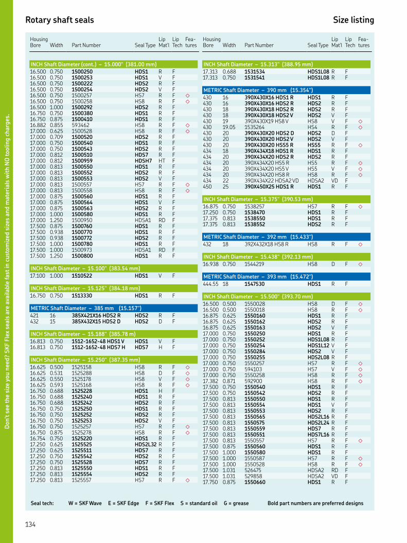
Seal tech: W = SKF Wave E = SKF Edge F = SKF Flex S = standard oil G = grease Bold part numbers are preferred designs
Rotary shaft seals Size listing
HousingBore Width
Part Number Seal Type
Lip Mat'l
Lip Tech
Fea-tures
INCH Shaft Diameter (cont.) – 15.000" (381.00 mm)
. . HDS R F. . HDS V F. . HDS R F. . HDS V F. . HS R F ◇
. . HS R F ◇
. . HDS R F. . HDS R F. . HDS R F. . HS R F ◇
. . HS R F ◇
. . HDS R F. . HDS R F. . HDS R F. . HDS R F. . HDSH HT F. . HDS R F. . HDS R F. . HDS V F. . HS R F ◇
. . HS R F ◇
. . HDS R F. . HDS V F. . HDS R F. . HDS R F. . HDSA RD F. . HDS R F. . HDS R F. . HDS R F. . HDS R F. . HDSA RD F. . HDS R F
INCH Shaft Diameter – 15.100" (383.54 mm)
. . HDS V F
INCH Shaft Diameter – 15.125" (384.18 mm)
. . HDS R F
METRIC Shaft Diameter – 385 mm (15.157")
XX HDS R HDS R F XX HDS D HDS D F
INCH Shaft Diameter – 15.188" (385.78 m)
. . -- HDS V HDS V F. . -- HDS H HDS H F
INCH Shaft Diameter – 15.250" (387.35 mm)
. . HS R F ◇
. . HS D F ◇
. . HS V F ◇
. . HS R F ◇
. . HDS H F. . HDS R F. . HDS R F. . HDS R F. . HDS R F. . HDS V F. . HS R F ◇
. . HS R F ◇
. . HDS R F. . HDSL R F. . HDS R F. . HDS R F. . HDS R F. . HDS R F. . HDS R F. . HS R F ◇
Housing Bore
Width
Part Number
Seal Type
Lip Mat'l
Lip Tech
Fea-tures
INCH Shaft Diameter – 15.313" (388.95 mm)
. . HDSL R F. . HDSL R F
METRIC Shaft Diameter – 390 mm (15.354")
XX HDS R HDS R F XX HDS R HDS R F XX HDS R HDS R F XX HDS V HDS V F XX HS V HS V F ◇
. HS R F ◇
XX HDS D HDS D F XX HDS V HDS V F XX HSS R HSS R F ◇
XX HDS R HDS R F XX HDS R HDS R F XX HS R HS R F ◇
XX HS V HS V F ◇
XX HS R HS R F ◇
XX HDSA VD HDSA VD F XX HDS R HDS R F
INCH Shaft Diameter – 15.375" (390.53 mm)
. . HS R F ◇
. . HDS R F. . HDS R F. . HDS R F
METRIC Shaft Diameter – 392 mm (15.433")
XX HS R HS R F ◇
INCH Shaft Diameter – 15.438" (392.13 mm)
. . HS D F ◇
METRIC Shaft Diameter – 393 mm (15.472")
. HDS R F
INCH Shaft Diameter – 15.500" (393.70 mm)
. . HS D F ◇
. . HS R F ◇
. . HDS R F. . HDS R F. . HDS V F. . HDS R F. . HDSL R F. . HDSL V F. . HDS V F. . HDSL R F. . HS R F ◇
. . HS V F ◇
. . HS R F ◇
. . HS R F ◇
. . HDS R F. . HDS R F. . HDS R F. . HDS V F. . HDS R F. . HDSL R F. . HDSL R F. . HDS R F. . HDSL R F. . HS R F ◇
. . HDS R F. . HDS R F. . HS R F ◇
. . HS R F ◇
. . HDSA RD F. . HDSA VD F. . HDS R F
Don’t s
ee t
he
size
you n
eed?
SK
F F
lex
seals
are
ava
ilable
fast
in c
ust
om
ized
siz
es a
nd m
ate
rials
wit
h N
O toolin
g c
harg
es.
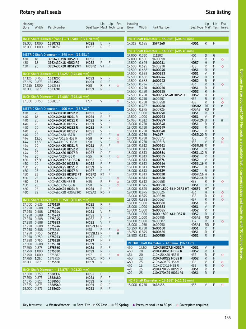
Rotary shaft seals Size listing
Key features: ▲ WasteWatcher ■ Bore-Tite ◤ SS Case ◎ SS Spring ◆ Pressure seal up to 50 psi ◇ Cover plate required
HousingBore Width
Part Number Seal Type
Lip Mat'l
Lip Tech
Fea-tures
INCH Shaft Diameter (cont.) – 15.500" (393.70 mm)
. . HDS D F. . HDS R F
METRIC Shaft Diameter – 395 mm (15.551")
XX HDS H HDS H F XX HDS R HDS R F XX HDSF VT HDSF VT F
INCH Shaft Diameter – 15.625" (396.88 mm)
. . HDS R F. . HDS R F. . HS R F ◇
. . HDS R F
INCH Shaft Diameter – 15.688" (398.48 mm)
. . HS V F ◇
METRIC Shaft Diameter – 400 mm (15.748")
XX HDS R HDS R F XX HDS R HDS R F XX HDS R HDS R F XX HDS V HDS V F XX HDS R HDS R F XX HDS V HDS V F XX HS R HS R F ◇
. XX. HS R HS R F ◇
. XX. HS V HS V F ◇
XX HDS R HDS R F XX HDS R HDS R F XX HDS R HDS R F XX HS R HS R F ◇
. XX. HDS R HDS R F XX HDS R HDS R F XX HDS R HDS R F XX HDS R HDS R F XX HDSF RT HDSF RT F XX HSS R HSS R F ◇
XX HS R HS R F ◇
XX HS R HS R F ◇
XX HDS R HDS R F XX HDSA RD HDSA RD F
INCH Shaft Diameter – 15.750" (400.05 mm)
. . HDS R F. . HDS R F. . HDS V F. . HDS D F. . HDS R F. . HDS V F. . HDSL R F. . HS R F ◇
. . HDSL R F ■
. . HDS R F. . HDS H F. . HDS R F. . HDS R F. . HDS R F. . HS R F ◇
. . HDSA RD F. . HDS R F
INCH Shaft Diameter – 15.875" (403.23 mm)
. . HDS D F. . HDS R F. . HDS R F. . HDS R F. . HDS R F
Housing Bore
Width
Part Number
Seal Type
Lip Mat'l
Lip Tech
Fea-tures
INCH Shaft Diameter – 15.938" (404.83 mm)
. . HDS R F
INCH Shaft Diameter – 16.000" (406.40 mm)
. . HD D G. . HS R F ◇
. . HDS H F. . HS R F ◇
. . HDS R F. . HDS V F. . HDS D F. . HDS R F. . HS R F ◇
. . HDS R F. . HDS R F. . -- HDS H HDS H F. . HS R F ◇
. . HS R F ◇
. . HDSH RT F ◤
. . HDSA RD F. . HDS R F. . HDS V F. . HDSL D F ■
. . HDS R F. . HDS R F. . HDS R F. . HDSL R F. . HS R F ◇
. . HS V F ◇
. . HDSL R F. . HDS R F. . HDSL R F. . HDS R F. . HDS V F. . HDSL R F. . HDS H F. . HDS R F. . HDSL H F. . HDSL R F. . HS R F ◇
. . HDS R F. . -- HDSF HT HDSF HT F. . HS H F ◇
. . HS D F ◇
. . HS R F ◇
. . HDS R F. . HDS V F. . HDS R F. . -- HDS R HDS R F. . HDSA RD F. . HS R F ◇
. . HDSA RD F. . HDS R F. . HDS R F. . HDS R F
METRIC Shaft Diameter – 410 mm (16.142")
. XX. HDS V HDS V F XX HDS R HDS R F XX HS R HS R F ◇
XX HDS R HDS R F XX HS V HS V F ◇
XX HS R HS R F ◇
XX HDS R HDS R F XX HDS R HDS R F
INCH Shaft Diameter – 16.188" (411.18 mm)
. . HS V F ◇
Don’t see th
e size you n
eed? S
KF F
lex seals a
re availa
ble fa
st in cu
stom
ized sizes a
nd m
ateria
ls with
NO
toolin
g ch
arg
es.

Seal tech: W = SKF Wave E = SKF Edge F = SKF Flex S = standard oil G = grease Bold part numbers are preferred designs
Rotary shaft seals Size listing
HousingBore Width
Part Number Seal Type
Lip Mat'l
Lip Tech
Fea-tures
INCH Shaft Diameter – 16.250" (412.75 mm)
. . HS R F ◇
. . HDS R F. . HS R F ◇
. . HDS R F. . HDSL R F. . HDS R F. . HDS R F. . HDSL R F. . HDS R F. . HS R F ◇
. . HDS R F. . HDSL R F. . HDS R F. . HDS V F. . HDSA RD F. . HDSA VD F
W/LIGHT LOAD SPRING. . HDS R F. . HS R F ◇
METRIC Shaft Diameter – 415 mm (16.339")
XX HDS R HDS R F
INCH Shaft Diameter – 16.375" (415.93 mm)
. . HDSA RD F. . HDS R F
METRIC Shaft Diameter – 418 mm (16.457")
XX HDS R HDS R F
INCH Shaft Diameter – 16.500" (419.10 mm)
. . HDS R F. . HDS R F. . HS R F ◇
. . HDS V F. . HDS R F. . HDS R F. . HDS V F. . HDSL R F. . HDS R F. . HS R F ◇
. . HS R F ◇
. . HDS R F. . HDS R F. . -- HDSH RT HDSH RT F. . HDS R F. . HDS R F. . HDS R F. . HDS V F. . HDS R F. . HDS V F. . -- HDS H HDS H F. . HDSL R F. . -- HDS H HDS H F. . HS R F ◇
. . HDS R F. . HS D F ◇
. . HDS R F. . HDSL D F. . HDS R F. . HDS R F
METRIC Shaft Diameter – 420 mm (16.535")
XX HDS R HDS R F XX HDS V HDS V F HDS D F XX HDS R HDS R F XX HDS V HDS V F
Housing Bore
Width
Part Number
Seal Type
Lip Mat'l
Lip Tech
Fea-tures
METRIC Shaft Diameter (cont.) – 420 mm (16.535")
XX HDS R HDS R F XX HS R HS R F ◇
XX HDS R HDS R F XX HDS R HDS R F XX HDS R HDS R F XX HDS V HDS V F XX HDSH VT HDSH VT F XX HDS R HDS R F
METRIC Shaft Diameter – 425 mm (16.732")
XX HDSF VT HDSF VT F XX HDSH VT HDSH VT F
INCH Shaft Diameter – 16.750" (425.45 mm)
. . HS R F ◇
. . HDS R F. . HDS R F. . HS R F ◇
. . HS R F ◇
. . HDS R F. . -- HS R HS R F ◇
. . HS R F ◇
. . HS R F ◇
. . HDS R F. . HDS R F
INCH Shaft Diameter – 16.875" (428.63 mm)
. . HS R F ◇
. . HS R F ◇
METRIC Shaft Diameter – 430 mm (16.929")
XX HDS R HDS R F XX HDS R HDS R F XX HDS R HDS R F XX HDS R HDS R F XX HDS V HDS V F XX HDS R HDS R F XX HDS V HDS V F XX HDS R HDS R F
INCH Shaft Diameter – 16.938" (430.23 mm)
. . HDSL R F
INCH Shaft Diameter – 17.000" (431.80 mm)
. . HDS R F. . HDS R F. . HDS V F. . HDS R F. . HS R F ◇
. . HS R F ◇
. . HS V F ◇
. . HDS R F. . HDS V F. . HDSL R F. . HDS R F. . HDS V F. . HDS R F. . HDS R F. . HDS V F. . HDS D F. . HDSL V F. . HS R F ◇
. . HDS D F. . HDS R F. . HDS R F. . HDS R F. . HDS V F. . HDS R F
Don’t s
ee t
he
size
you n
eed?
SK
F F
lex
seals
are
ava
ilable
fast
in c
ust
om
ized
siz
es a
nd m
ate
rials
wit
h N
O toolin
g c
harg
es.

Rotary shaft seals Size listing
Key features: ▲ WasteWatcher ■ Bore-Tite ◤ SS Case ◎ SS Spring ◆ Pressure seal up to 50 psi ◇ Cover plate required
HousingBore Width
Part Number Seal Type
Lip Mat'l
Lip Tech
Fea-tures
INCH Shaft Diameter (cont.) – 17.000" (431.80 mm)
. . HDS V F. . HDS R F. . HS D F ◇
. . HS R F ◇
. . HS R F ◇
. . HDS R F. . HDSL D F. . HDS D F. . HDS R F. . HDS D F. . HDSA RD F. . HDS R F
METRIC Shaft Diameter – 435 mm (17.126")
XX HDS R HDS R F XX HSS R HSS R F ◇
INCH Shaft Diameter – 17.250" (438.15 mm)
. . HDS R F ■
. . HDS R F. . HDS R F. . HS R F ◇
. . HS R F ◇
. . HDS R F. . HDS R F. . HDS R F. . HS R F ◇
. . HDS R F
METRIC Shaft Diameter – 440 mm (17.323")
XX HDS R HDS R F XX HS R HS R F ◇
XX HDS R HDS R F XX HDS V HDS V F XX HDS R HDS R F XX HS R HS R F ◇
XX HS R HS R F ◇
XX HS V HS V F ◇
XX HDS R HDS R F XX HS R HS R F ◇
INCH Shaft Diameter – 17.375" (441.33 mm)
. . HDS R F
INCH Shaft Diameter – 17.438" (442.93 mm)
. . HDS R F
INCH Shaft Diameter – 17.500" (444.50 mm)
. . HS R F ◇
. . HDSF VU F. . HDS R F. . HDS R F. . HDS R F. . HDS V F. . HDS R F. . HDS D F. . HDS R F. . HDS V F. . HS D F ◇
. . HS R F ◇
. . HDS R F. . HDS R F. . HDS R F. . HDS R F. . HDS R F. . HDS D F. . HDSL R F. . HS R F ◇
Housing Bore
Width
Part Number
Seal Type
Lip Mat'l
Lip Tech
Fea-tures
INCH Shaft Diameter (cont.) – 17.500" (444.50 mm)
. . HDS H F. . HS R F ◇
. . HDS R F. . HS R F ◇
. . HDS R F. . HS R F ◇
. . HDS R F
METRIC Shaft Diameter – 445 mm (17.520")
XX HDS R HDS R F XX HDS R HDS R F
INCH Shaft Diameter – 17.531" (445.29 mm)
. . HDS V F
INCH Shaft Diameter – 17.625" (447.68 mm)
. . HDS R F. . HDS V F. . HDS R F. . HDS R F. . HDS R F. . HDS R F. . HDS R F
METRIC Shaft Diameter – 448 mm (17.638")
XX HDS R HDS R F
METRIC Shaft Diameter – 450 mm (17.717")
XX HDS R HDS R F XX HDS R HDS R F XX HDS V HDS V F XX HS R HS R F ◇
XX HDS R HDS R F XX HDS R HDS R F
INCH Shaft Diameter – 17.750" (450.85 mm)
. . HS R F ◇
. . HS R F ◇
. . HDS R F. . HDS R F. . HS R F ◇
. . HS R F ◇
. . HDS R F
INCH Shaft Diameter – 17.818" (452.58 mm)
. . HDS R F
INCH Shaft Diameter – 17.874" (454.00 mm)
. . HDSL R F. . HDS R F
INCH Shaft Diameter – 17.875" (454.03 mm)
. . HDS D F. . HDS R F. . HDS R F. . HDS R F. . HDS R F
INCH Shaft Diameter – 17.938" (455.63 mm)
. . HDS R F
INCH Shaft Diameter – 18.000" (457.20 mm)
. . HS R F ◇
. . HS R F ◇
. . HDS V F. . HDS V F
Don’t see th
e size you n
eed? S
KF F
lex seals a
re availa
ble fa
st in cu
stom
ized sizes a
nd m
ateria
ls with
NO
toolin
g ch
arg
es.

Seal tech: W = SKF Wave E = SKF Edge F = SKF Flex S = standard oil G = grease Bold part numbers are preferred designs
Rotary shaft seals Size listing
HousingBore Width
Part Number Seal Type
Lip Mat'l
Lip Tech
Fea-tures
INCH Shaft Diameter (cont.) – 18.000" (457.20 mm)
. . HDS R F. . HDS D F. . HDS R F. . -- HDS H HDS H F. . HS R F ◇
. . HDS R F. . -- HDS H HDS H F. . HS R F ◇
. . HS R F ◇
. . HDS R F. . HS R F ◇
. . HDS R F. . HDS R F. . HDS D F. . HS R F ◇
. . HS D F ◇
. . HS R F ◇
. . HDS R F. . HDS R F. . HDS V F. . HDS R F. . HS R F ◇
. . HDS R F. . HDS R F. . HDS V F. . HDS V F. . HDSA VD F. . HDSA RD F. . HDSA VD F. . HS R F ◇
. . HDS R F
INCH Shaft Diameter – 18.063" (458.80 mm)
. . -- HDS R HDS R F
METRIC Shaft Diameter – 460 mm (18.110")
XX HDS R HDS R F XX HDS V HDS V F XX HDS R HDS R F . XX HDS R HDS R F XX HDS H HDS H F XX HDSF VT HDSF VT F XX HDSH VT HDSH VT F XX HS R HS R F ◇
. . HDS R F XX HDS R HDS R F
INCH Shaft Diameter – 18.120" (460.25 mm)
. . HDS R F
INCH Shaft Diameter – 18.175" (461.65 mm)
. . HS R F ◇
INCH Shaft Diameter – 18.250" (463.55 mm)
. . HDS R F. . HDS R F. . HS R F ◇
. . HDS H F. . HS R F ◇
INCH Shaft Diameter – 18.313" (465.15 mm)
. . HDS R F
INCH Shaft Diameter – 18.375" (466.73 mm)
. . HDS R F. . HDS R F. . -- HDS H HDS H F. . HDSL R F
Housing Bore
Width
Part Number
Seal Type
Lip Mat'l
Lip Tech
Fea-tures
INCH Shaft Diameter (cont.) – 18.375" (466.73 mm)
. . -- HDS H HDS H F. . HDS R F. . HDS R F
METRIC Shaft Diameter – 467 mm (18.386")
XX HDS V HDS V F
METRIC Shaft Diameter – 468 mm (18.425")
XX HS R HS R F ◇
INCH Shaft Diameter – 18.500" (469.90 mm)
. . HDS R F. . HS R F ◇
. . HS D F ◇
. . HDS R F. . HDS R F. . HDS R F. . HDS V F. . HDS R F. . -- HSS R HSS R F ◇
. . -- HS R HS R F ◇
. . -- HS R HS R F ◇
. . HDS R F. . HDS R F. . HDS V F. . HDS R F. . HDSL R F. . HDSA RD F. . HDSA VD F. . HDS R F. . HS R F ◇
METRIC Shaft Diameter – 470 mm (18.504")
XX HDS R HDS R F XX HDS V HDS V F XX HDS R HDS R F XX HDS V HDS V F . XX. HS R HS R F ◇
XX HDS R HDS R F XX HDS R HDS R F XX HDS R HDS R F XX HDS R HDS R F XX HDSA RR HDSA RR F
INCH Shaft Diameter – 18.750" (476.25 mm)
. . HS R F ◇
. . HDS R F. . HDS R F. . HS R F ◇
. . HDS R F. . HS H F ◇
. . HS R F ◇
. . HDS R F. . HDS R F. . HS R F ◇
INCH Shaft Diameter – 18.875" (479.43 mm)
. . HDS R F
METRIC Shaft Diameter – 480 mm (18.898")
XX HS H HS H F ◇
XX HDS D HDS D F XX HDS R HDS R F XX HDS V HDS V F XX HDS D HDS D F XX HS R HS R F ◇
XX HDSA VD HDSA VD F XX HS R HS R F ◇
Don’t s
ee t
he
size
you n
eed?
SK
F F
lex
seals
are
ava
ilable
fast
in c
ust
om
ized
siz
es a
nd m
ate
rials
wit
h N
O toolin
g c
harg
es.

Rotary shaft seals Size listing
Key features: ▲ WasteWatcher ■ Bore-Tite ◤ SS Case ◎ SS Spring ◆ Pressure seal up to 50 psi ◇ Cover plate required
HousingBore Width
Part Number Seal Type
Lip Mat'l
Lip Tech
Fea-tures
METRIC Shaft Diameter (cont.) – 480 mm (18.898")
XX HDS R HDS R F XX HDS R HDS R F XX HS R HS R F ◇
XX HDS R HDS R F XX HDS R HDS R F
INCH Shaft Diameter – 19.000" (482.60 mm)
. . HDSL H F. . HDS R F. . HDS R F. . HDS V F. . -- HDS H HDS H F. . HDSL R F. . HDSL R F. . HDS H F. . HDS R F. . -- HDS H HDS H F. . HDSK R F. . HS R F ◇
. . HS R F ◇
. . HDS D F. . HDSL D F. . HS H F ◇
. . HDS R F. . HDS R F. . HDSL R F. . HS R F ◇
. . HS R F ◇
. . -- HS H HS H F ◇
. . HDSF VT F. . HDS R F. . HDS R F. . HDS V F. . HDSL V F. . HDS R F. . HDS R F. . HDS R F. . HDS R F. . HDS R F
METRIC Shaft Diameter – 485 mm (19.485")
XX HDS R HDS R F
INCH Shaft Diameter – 19.125" (485.78 mm)
. . HS R F ◇
INCH Shaft Diameter – 19.250" (488.95 mm)
. . HDS R F. . HDS R F. . HDS R F. . HDSA RD F. . HDS R F. . HDS R F. . HDS R F
METRIC Shaft Diameter – 490 mm (19.291")
XX HDS R HDS R F XX HDS V HDS V F . XX. HS D HS D F ◇
XX HS R HS R F ◇
INCH Shaft Diameter – 19.375" (492.13 mm)
. . HS R F ◇
INCH Shaft Diameter – 19.500" (495.30 mm)
. . HDS R F. . HDS R F. . HDS R F
Housing Bore
Width
Part Number
Seal Type
Lip Mat'l
Lip Tech
Fea-tures
INCH Shaft Diameter (cont.) – 19.500" (495.30 mm)
. . HDS R F. . HDS R F. . -- HDSL R HDSL R F. . HDS R F. . HS R F ◇
. . HS R F ◇
. . HDS R F. . HDS V F. . HDS V F. . HDS R F. . -- HS R HS R F ◇
INCH Shaft Diameter – 19.625" (498.48 mm)
. . HDS R F
METRIC Shaft Diameter – 500 mm (19.685")
XX HDS V HDS V F XX HDS V HDS V F XX HDS R HDS R F XX HDS V HDS V F XX HDS V HDS V F ◤
XX HDS V HDS V F XX HSS H HSS H F ◇
XX HSS H HSS H F ◇
XX HSS R HSS R F ◇
XX HSS V HSS V F ◇
XX HDSA RD HDSA RD F XX HS R HS R F ◇
XX HDS D HDS D F XX HDS D HDS D F XX HDS R HDS R F XX HS V HS V F ◇
XX HSS R HSS R F ◇
XX HDS V HDS V F XX HDS R HDS R F XX HDSF VT HDSF VT F XX HDSH VT HDSH VT F HDS R F XX HDS R HDS R F
INCH Shaft Diameter – 19.750" (501.65 mm)
. . HDS R F. . HDS R F. . HS R F ◇
. . HS R F ◇
. . HDS V F. . HDS R F. . HDS R F
INCH Shaft Diameter – 19.875" (504.83 mm)
. . HDS R F
METRIC Shaft Diameter – 505 mm (19.882")
. XX HDS R HDS R F
INCH Shaft Diameter – 19.938" (506.43 mm)
. . HDS R F
INCH Shaft Diameter – 20.000" (508.00 mm)
. . HS R F ◇
. . HDS R F. . HS R F ◇
. . HDS R F. . HDSL R F. . HDS R F. . HDS V F. . HDS R F. . HS R F ◇
Don’t see th
e size you n
eed? S
KF F
lex seals a
re availa
ble fa
st in cu
stom
ized sizes a
nd m
ateria
ls with
NO
toolin
g ch
arg
es.
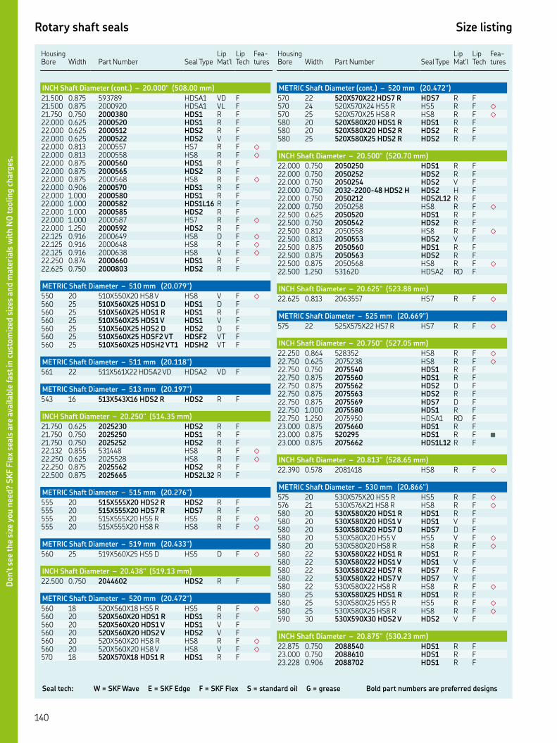
Seal tech: W = SKF Wave E = SKF Edge F = SKF Flex S = standard oil G = grease Bold part numbers are preferred designs
Rotary shaft seals Size listing
HousingBore Width
Part Number Seal Type
Lip Mat'l
Lip Tech
Fea-tures
INCH Shaft Diameter (cont.) – 20.000" (508.00 mm)
. . HDSA VD F. . HDSA VL F. . HDS R F. . HDS R F. . HDS R F. . HDS V F. . HS R F ◇
. . HS R F ◇
. . HDS R F. . HDS R F. . HS R F ◇
. . HDS R F. . HDS R F. . HDSL R F. . HDS R F. . HS R F ◇
. . HDS R F. . HS D F ◇
. . HS R F ◇
. . HS V F ◇
. . HDS R F. . HDS R F
METRIC Shaft Diameter – 510 mm (20.079")
XX HS V HS V F ◇
XX HDS D HDS D F XX HDS R HDS R F XX HDS V HDS V F XX HDS D HDS D F XX HDSF VT HDSF VT F XX HDSH VT HDSH VT F
METRIC Shaft Diameter – 511 mm (20.118")
XX HDSA VD HDSA VD F
METRIC Shaft Diameter – 513 mm (20.197")
XX HDS R HDS R F
INCH Shaft Diameter – 20.250" (514.35 mm)
. . HDS R F. . HDS R F. . HDS R F. . HS R F ◇
. . HS R F ◇
. . HDS R F. . HDSL R F
METRIC Shaft Diameter – 515 mm (20.276")
XX HDS R HDS R F XX HDS R HDS R F XX HS R HS R F ◇
XX HS R HS R F ◇
METRIC Shaft Diameter – 519 mm (20.433")
XX HS D HS D F ◇
INCH Shaft Diameter – 20.438" (519.13 mm)
. . HDS R F
METRIC Shaft Diameter – 520 mm (20.472")
XX HS R HS R F ◇
XX HDS R HDS R F XX HDS V HDS V F XX HDS V HDS V F XX HS R HS R F ◇
XX HS V HS V F ◇
XX HDS R HDS R F
Housing Bore
Width
Part Number
Seal Type
Lip Mat'l
Lip Tech
Fea-tures
METRIC Shaft Diameter (cont.) – 520 mm (20.472")
XX HDS R HDS R F XX HS R HS R F ◇
XX HS R HS R F ◇
XX HDS R HDS R F XX HDS R HDS R F XX HDS R HDS R F
INCH Shaft Diameter – 20.500" (520.70 mm)
. . HDS R F. . HDS R F. . HDS V F. . -- HDS H HDS H F. . HDSL R F. . HS R F ◇
. . HDS R F. . HDS R F. . HS R F ◇
. . HDS V F. . HDS R F. . HDS R F. . HS R F ◇
. . HDSA RD F
INCH Shaft Diameter – 20.625" (523.88 mm)
. . HS R F ◇
METRIC Shaft Diameter – 525 mm (20.669")
XX HS R HS R F ◇
INCH Shaft Diameter – 20.750" (527.05 mm)
. . HS R F ◇
. . HS R F ◇
. . HDS R F. . HDS R F. . HDS D F. . HDS R F. . HDS D F. . HDS R F. . HDSA RD F. . HDS R F. . HDS R F ■
. . HDSL R F
INCH Shaft Diameter – 20.813" (528.65 mm)
. . HS R F ◇
METRIC Shaft Diameter – 530 mm (20.866")
XX HS R HS R F ◇
XX HS R HS R F ◇
XX HDS R HDS R F XX HDS V HDS V F XX HDS D HDS D F XX HS V HS V F ◇
XX HS R HS R F ◇
XX HDS R HDS R F XX HDS V HDS V F XX HDS R HDS R F XX HDS V HDS V F XX HS R HS R F ◇
XX HDS R HDS R F XX HS R HS R F ◇
XX HS R HS R F ◇
XX HDS V HDS V F
INCH Shaft Diameter – 20.875" (530.23 mm)
. . HDS R F. . HDS R F. . HDS R F
Don’t s
ee t
he
size
you n
eed?
SK
F F
lex
seals
are
ava
ilable
fast
in c
ust
om
ized
siz
es a
nd m
ate
rials
wit
h N
O toolin
g c
harg
es.

Rotary shaft seals Size listing
Key features: ▲ WasteWatcher ■ Bore-Tite ◤ SS Case ◎ SS Spring ◆ Pressure seal up to 50 psi ◇ Cover plate required
HousingBore Width
Part Number Seal Type
Lip Mat'l
Lip Tech
Fea-tures
INCH Shaft Diameter – 21.000" (533.40 mm)
. . HDS R F. . -- HDS R HDS R F. . HS R F ◇
. . HS R F ◇
. . HDS R F. . HS R F ◇
. . HDS R F. . HS R F ◇
. . HDS R F. . HDSL R F. . HS R F ◇
. . HDSH RT F ◤
. . HS R F ◇
. . HS R F ◇
. . HS V F ◇
. . HDS R F. . HDSL R F. . HDSL R F. . HDS R F. . HDS R F. . HDS R F
INCH Shaft Diameter – 21.125" (536.58 mm)
. . HDS V F
INCH Shaft Diameter – 21.250" (539.75 mm)
. . HS R F ◇
. . HDS R F. . HDS R F. . HDS R F. . HDS R F. . HDS R F. . HDS V F
METRIC Shaft Diameter – 540 mm (21.260")
XX HDS R HDS R F XX HS R HS R F ◇
XX HDS R HDS R F XX HDS D HDS D F XX HDS V HDS V F XX HDS R HDS R F XX HDS V HDS V F XX HDSF VT HDSF VT F XX HDSH VT HDSH VT F
INCH Shaft Diameter – 21.438" (544.53 mm)
. . HDS R F. . HDS R F
METRIC Shaft Diameter – 545 mm (21.457")
XX HDS R HDS R F
INCH Shaft Diameter – 21.500" (546.10 mm)
. . HS R F ◇
. . HDS R F. . HDS R F. . HDS V F. . HS R F ◇
. . HDS R F. . HDS R F. . HDS V F. . HDS R F. . HDS H F. . HDS R F. . HDSL R F. . HS R F ◇
. . HDS V F. . HDS R F. . HDS R F
Housing Bore
Width
Part Number
Seal Type
Lip Mat'l
Lip Tech
Fea-tures
INCH Shaft Diameter – 21.625" (549.28 mm)
. . HS R F ◇
. . HDS R F
METRIC Shaft Diameter – 550 mm (21.654")
XX HDS R HDS R F XX HDS V HDS V F XX HDS R HDS R F XX HDS R HDS R F XX HS R HS R F ◇
XX HDS R HDS R F XX HDS R HDS R F XX HDSA RD HDSA R F
INCH Shaft Diameter – 21.745" (552.32 mm)
. . HDS R F
INCH Shaft Diameter – 21.750" (552.45 mm)
. . HDS R F. . HDS R F. . HS R F ◇
. . HDS R F. . HDS R F. . HDSL R F. . HDS R F. . HDSA DD F. . HDSA RD F. . HDS R F. . HDSL R F
INCH Shaft Diameter – 22.000" (558.80 mm)
. . HS R F ◇
. . HDS R F. . HDS R F. . HDS R F. . HDS V F. . HDS H F. . -- HDS R HDS R F. . HDSA RD F. . HDS R F. . HDS D F. . HDS R F. . HS D F ◇
. . HDS R F. . HS V F ◇
. . HDS R F. . HS R F ◇
. . HS D F ◇
. . HDS R F. . HDS D F. . HDS R F. . HDSL R F. . -- HDS R HDS R F. . HDSL R F. . HDSA RL F. . HS D F ◇
. . HDS R F. . HDSL R F. . HDS D F. . HDS R F. . HDS R F
METRIC Shaft Diameter – 560 mm (22.047")
XX HDS R HDS R F XX HDS R HDS R F XX HDS V HDS V F XX HDS V HDS V F XX HDS R HDS R F XX HDS R HDS R F XX HDS V HDS V F
Don’t see th
e size you n
eed? S
KF F
lex seals a
re availa
ble fa
st in cu
stom
ized sizes a
nd m
ateria
ls with
NO
toolin
g ch
arg
es.

Seal tech: W = SKF Wave E = SKF Edge F = SKF Flex S = standard oil G = grease Bold part numbers are preferred designs
Rotary shaft seals Size listing
HousingBore Width
Part Number Seal Type
Lip Mat'l
Lip Tech
Fea-tures
METRIC Shaft Diameter (cont.) – 560 mm (22.047")
XX HDSA VD HDSA V F . XX. HDS R HDS R F
INCH Shaft Diameter – 22.125" (561.98 mm)
. . HS R F ◇
. . HS R F ◇
. . HDS R F
INCH Shaft Diameter – 22.250" (565.15 mm)
. . HDS D F. . HDS D F. . HDS R F. . HDS R F. . HDS R F. . HDSL R F. . HS R F ◇
. . HDS R F
INCH Shaft Diameter – 22.375" (568.33 mm)
. . HDS R F. . HDS R F. . HDSL R F
INCH Shaft Diameter – 22.438" (569.93 mm)
. . HDS V F. . HDS R F
METRIC Shaft Diameter – 570 mm (22.441")
XX HS H HS H F ◇
XX HDS R HDS R F XX HDS R HDS R F XX HDS R HDS R F XX HDS R HDS R F XX HDSL R HDSL R F
INCH Shaft Diameter – 22.500" (571.50 mm)
. . HDS R F. . HS R F ◇
. . HDS R F. . HDS V F. . HDSH VT F. . HDS R F
INCH Shaft Diameter – 22.638" (575.01 mm)
. . HS D F ◇
INCH Shaft Diameter – 22.750" (577.85 mm)
. . HS R F ◇
. . HS R F ◇
. . HDS R F. . HDS R F
METRIC Shaft Diameter – 578 mm (22.756")
XX HDS R HDS R F
INCH Shaft Diameter – 22.814" (579.48 mm)
. . HS R F ◇
METRIC Shaft Diameter – 580 mm (22.835")
XX HS R HS R F ◇
XX HDS D HDS D F XX HDS R HDS R F XX HSSG R HSSG R F ◇
XX HDSA RD HDSA RD F . HDS R F XX HDS R HDS R F
Housing Bore
Width
Part Number
Seal Type
Lip Mat'l
Lip Tech
Fea-tures
METRIC Shaft Diameter (cont.) – 580 mm (22.835")
XX HDS D HDS D F XX HS V HS V F ◇
XX HS R HS R F ◇
XX HDSA RD HDSA RD F XX HDS V HDS V F
INCH Shaft Diameter – 23.000" (584.20 mm)
. . HDS R F. . HDSL R F. . HDS R F. . HDS V F. . HDSL R F. . -- HDS H HDS H F. . HS R F ◇
. . HS R F ◇
. . HDS R F. . HDS D F. . HDS R F. . HDS V F. . HS R F ◇
. . HDS R F. . HDS R F ◤◎
. . HS D F ◇
. . HS R F ◇
. . HDS R F. . HDS R F. . HDS R F. . HDS R F. . HDSA RD F. . HDS R F. . HDS R F. . HDS V F. . HDS V F. . HDS R F
METRIC Shaft Diameter – 585 mm (23.031")
XX HDS R HDS R F
INCH Shaft Diameter – 23.208" (589.48 mm)
. . HS R F ◇
METRIC Shaft Diameter – 590 mm (23.228")
XX HDS R HDS R F XX HDS R HDS R F XX HDS D HDS D F. . HS V F ◇
XX HDS R HDS R F XX HS R HS R F ◇
INCH Shaft Diameter – 23.250" (590.55 mm)
. . HDS R F. . HDS R F. . HDS R F. . HDS R F
INCH Shaft Diameter – 23.375" (593.73 mm)
. . HS R F ◇
INCH Shaft Diameter – 23.500" (596.90 mm)
. . HS R F ◇
. . HDS R F. . HDS R F. . HDS V F. . HS R F ◇
. . HDS R F. . HDS V F. . HDSL R F. . HDS R F
Don’t s
ee t
he
size
you n
eed?
SK
F F
lex
seals
are
ava
ilable
fast
in c
ust
om
ized
siz
es a
nd m
ate
rials
wit
h N
O toolin
g c
harg
es.
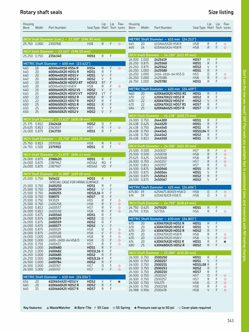
Rotary shaft seals Size listing
Key features: ▲ WasteWatcher ■ Bore-Tite ◤ SS Case ◎ SS Spring ◆ Pressure seal up to 50 psi ◇ Cover plate required
HousingBore Width
Part Number Seal Type
Lip Mat'l
Lip Tech
Fea-tures
INCH Shaft Diameter (cont.) – 23.500" (596.90 mm)
. . HS R F ◇
INCH Shaft Diameter – 23.563" (598.50 mm)
. . HDS R F
METRIC Shaft Diameter – 600 mm (23.622")
XX HSS R HSS R F ◇
XX HDS R HDS R F XX HDS V HDS V F XX HDS V HDS V F XX HDSF RT HDSF RT F XX HS R HS R F ◇
XX HDS V HDS V F XX HDSF VT HDSF VT F XX HDS R HDS R F XX HDS R HDS R F XX HDS R HDS R F XX HDS V HDS V F XX HDS V HDS V F
INCH Shaft Diameter – 23.625" (600.08 mm)
. . HDS D F. . HS R F ◇
. . HDS R F
INCH Shaft Diameter – 23.750" (603.25 mm)
. . HS R F ◇
. . HDS R F
INCH Shaft Diameter – 23.875" (606.43 mm)
. . HDS R F. . HDSA RD F. . HDSA VD F
INCH Shaft Diameter – 24.000" (609.60 mm)
. . HDS R FSPECIAL CASE FOR VRING SURFACE
. . HDS R F. . HDS V F. . HDSL R F. . HDS R F. . HS R F ◇
. . HS R F ◇
. . HS R F ◇
. . HS R F ◇
. . HDS R F. . HDS D F. . HDS R F. . HDS V F. . HS D F ◇
. . HS V F ◇
. . HS R F ◇
. . -- HS D HS D F ◇
. . HS R F ◇
. . HDS R F. . HDSL R F. . HDS R F. . HDSL R F. . HDS R F. . HS D F ◇
. . HS V F ◇
METRIC Shaft Diameter – 610 mm (24.016")
XX HDS V HDS V F ■
XX HDS R HDS R F XX HDS R HDS R F
Housing Bore
Width
Part Number
Seal Type
Lip Mat'l
Lip Tech
Fea-tures
METRIC Shaft Diameter – 615 mm (24.213")
XX HS R HS R F ◇
XX HS R HS R F ◇
INCH Shaft Diameter – 24.250" (615.95 mm)
. . HDS H F. . HDS R F. . HDS V F. . HDS R F. . -- HS D HS D F ◇
. . HS R F ◇
. . HDS R F
METRIC Shaft Diameter – 620 mm (24.409")
XX HDS R HDS R F XX HDS R HDS R F XX HDS V HDS V F XX HDS R HDS R F XX HDS R HDS R F
INCH Shaft Diameter – 24.438" (620.73 mm)
. . HDS R F. . HDS R F. . HDS R F. . HDSL R F. . HDS R F. . HDS R F
INCH Shaft Diameter – 24.500" (622.30 mm)
. . HS R F ◇
. . HS R F ◇
. . HS R F ◇
. . HS R F ◇
. . HS R F ◇
. . HDS R F. . HDS V F. . HDS R F. . HDS V F
METRIC Shaft Diameter – 625 mm (24.606")
. X.X HS D HS D F ◇
XX HS D HS D F ◇
INCH Shaft Diameter – 24.750" (628.65 mm)
. . HDS R F. . HS R F ◇
METRIC Shaft Diameter – 630 mm (24.803")
XX HDS R HDS R F XX HDS V HDS V F XX HDS R HDS R F XX HS R HS R F ◇
XX HS V HS V F ◇
XX HDS R HDS R F ■
XX HDS R HDS R F
INCH Shaft Diameter – 25.000" (635.00 mm)
. . HDS R F. . HDS V F. . HDSL R F. . HDS R F. . HDS R F. . HS D F ◇
. . HS R F ◇
. . HS D F ◇
. . HS R F ◇
. . HS V F ◇
Don’t see th
e size you n
eed? S
KF F
lex seals a
re availa
ble fa
st in cu
stom
ized sizes a
nd m
ateria
ls with
NO
toolin
g ch
arg
es.
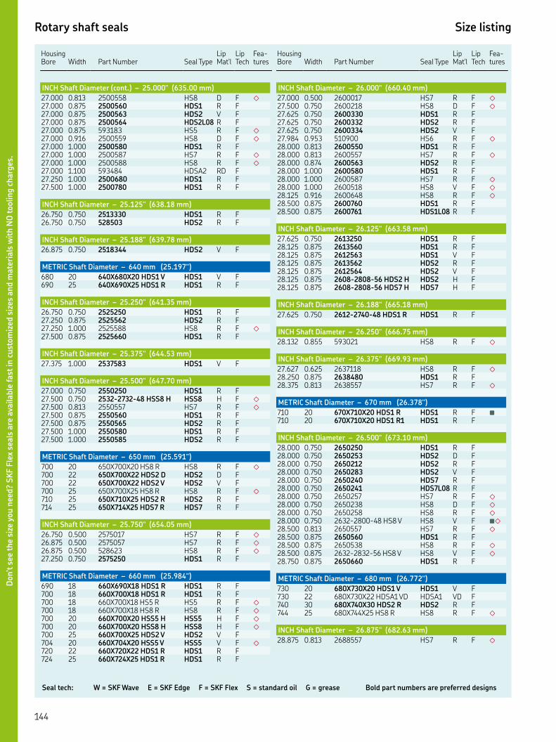
Seal tech: W = SKF Wave E = SKF Edge F = SKF Flex S = standard oil G = grease Bold part numbers are preferred designs
Rotary shaft seals Size listing
HousingBore Width
Part Number Seal Type
Lip Mat'l
Lip Tech
Fea-tures
INCH Shaft Diameter (cont.) – 25.000" (635.00 mm)
. . HS D F ◇
. . HDS R F. . HDS V F. . HDSL R F. . HS R F ◇
. . HS D F ◇
. . HDS R F. . HS R F ◇
. . HS R F ◇
. . HDSA RD F. . HDS R F. . HDS R F
INCH Shaft Diameter – 25.125" (638.18 mm)
. . HDS R F. . HDS R F
INCH Shaft Diameter – 25.188" (639.78 mm)
. . HDS V F
METRIC Shaft Diameter – 640 mm (25.197")
XX HDS V HDS V F XX HDS R HDS R F
INCH Shaft Diameter – 25.250" (641.35 mm)
. . HDS R F. . HDS R F. . HS R F ◇
. . HDS R F
INCH Shaft Diameter – 25.375" (644.53 mm)
. . HDS V F
INCH Shaft Diameter – 25.500" (647.70 mm)
. . HDS R F. . -- HSS H HSS H F ◇
. . HS R F ◇
. . HDS R F. . HDS R F. . HDS R F. . HDS R F
METRIC Shaft Diameter – 650 mm (25.591")
XX HS R HS R F ◇
XX HDS D HDS D F XX HDS V HDS V F XX HS R HS R F ◇
XX HDS R HDS R F XX HDS R HDS R F
INCH Shaft Diameter – 25.750" (654.05 mm)
. . HS R F ◇
. . HS R F ◇
. . HS R F ◇
. . HDS R F
METRIC Shaft Diameter – 660 mm (25.984")
XX HDS R HDS R F XX HDS R HDS R F XX HS R HS R F ◇
XX HS R HS R F ◇
XX HSS H HSS H F ◇
XX HSS H HSS H F ◇
XX HDS V HDS V F XX HSS V HSS V F ◇
XX HDS R HDS R F XX HDS R HDS R F
Housing Bore
Width
Part Number
Seal Type
Lip Mat'l
Lip Tech
Fea-tures
INCH Shaft Diameter – 26.000" (660.40 mm)
. . HS R F ◇
. . HS D F ◇
. . HDS R F. . HDS R F. . HDS V F. . HS R F ◇
. . HDS R F. . HS R F ◇
. . HDS R F. . HDS R F. . HS R F ◇
. . HS V F ◇
. . HS R F ◇
. . HDS R F. . HDSL R F
INCH Shaft Diameter – 26.125" (663.58 mm)
. . HDS R F. . HDS R F. . HDS V F. . HDS R F. . HDS V F. . -- HDS H HDS H F. . -- HDS H HDS H F
INCH Shaft Diameter – 26.188" (665.18 mm)
. . -- HDS R HDS R F
INCH Shaft Diameter – 26.250" (666.75 mm)
. . HS R F ◇
INCH Shaft Diameter – 26.375" (669.93 mm)
. . HS R F ◇
. . HDS R F. . HS R F ◇
METRIC Shaft Diameter – 670 mm (26.378")
XX HDS R HDS R F ■
XX HDS R HDS R F
INCH Shaft Diameter – 26.500" (673.10 mm)
. . HDS R F. . HDS D F. . HDS R F. . HDS V F. . HDS R F. . HDSL R F. . HS R F ◇
. . HS D F ◇
. . HS R F ◇
. . -- HS V HS V F ■◇
. . HS R F ◇
. . HDS R F. . HS R F ◇
. . -- HS V HS V F ◇
. . HDS R F
METRIC Shaft Diameter – 680 mm (26.772")
XX HDS V HDS V F XX HDSA VD HDSA VD F XX HDS R HDS R F XX HS R HS R F ◇
INCH Shaft Diameter – 26.875" (682.63 mm)
. . HS R F ◇
Don’t s
ee t
he
size
you n
eed?
SK
F F
lex
seals
are
ava
ilable
fast
in c
ust
om
ized
siz
es a
nd m
ate
rials
wit
h N
O toolin
g c
harg
es.

Rotary shaft seals Size listing
Key features: ▲ WasteWatcher ■ Bore-Tite ◤ SS Case ◎ SS Spring ◆ Pressure seal up to 50 psi ◇ Cover plate required
HousingBore Width
Part Number Seal Type
Lip Mat'l
Lip Tech
Fea-tures
INCH Shaft Diameter – 26.938" (684.23 mm)
. . HDS R F
METRIC Shaft Diameter – 685 mm (26.696")
XX HDS R HDS R F
INCH Shaft Diameter – 27.000" (685.80 mm)
. . HS R F ◇
. . HDS R F. . HDS R F. . HDS R F. . HS D F ◇
. . HS R F ◇
. . HDSL R F. . HDS R F. . HDS V F. . HDS R F. . HDS V F. . HDS V F. . HDS R F. . HDS R F
METRIC Shaft Diameter – 690 mm (27.165")
XX HDS R HDS R F
INCH Shaft Diameter – 27.250" (692.15 mm)
. . HDS R F. . HDS R F
INCH Shaft Diameter – 27.500" (698.50 mm)
. . HS R F ◇
. . HDS R F. . HS R F ◇
. . HDS R F. . HDSL R F. . HDS R F. . HDSL R F. . HDS R F
METRIC Shaft Diameter – 700 mm (27.559")
XX HDS R HDS R F XX HS D HS D F ◇
XX HDS R HDS R F XX HDS V HDS V F XX HDSF VT HDSF VT F XX HDSH VT HDSH VT F. . HDSA RL F
INCH Shaft Diameter – 27.625" (701.68 mm)
. . HDS R F. . HDS R F
INCH Shaft Diameter – 27.875" (708.03 mm)
. . HDS R F. . HDS R F. . HS R F ◇
METRIC Shaft Diameter – 710 mm (27.953")
XX HDSL. V HDS V F XX HDS V HDS V F XX HDS R HDS R F XX HDS V HDS V F XX HSS H HSS H F ◇
XX HSS H HSS H F ◇
XX HDS D HDS D F XX. HDS D HDS D F XX HS D HS D F ◇
XX HDSL R HDSL R F
Housing Bore
Width
Part Number
Seal Type
Lip Mat'l
Lip Tech
Fea-tures
INCH Shaft Diameter – 28.000" (711.20 mm)
. . HDS R F. . HDS R F. . HDS R F. . HDSL R F. . HS R F ◇
. . HDS R F. . HS R F ◇
. . HDS R F. . HDS V F. . HDS R F. . HDSL R F. . HDS R F. . HDS R F
INCH Shaft Diameter – 28.038" (712.17 mm)
. . HDSA VL F
METRIC Shaft Diameter – 715 mm (28.150")
XX HDS D HDS D F
METRIC Shaft Diameter – 720 mm (28.346")
XX HDS R HDS R F XX HS D HS D F ◇
XX HDS R HDS R F XX HDS R HDS R F
INCH Shaft Diameter – 28.500" (712.17 mm)
. . HDS R F. . HDS R F. . HDSL V F. . HDS R F. . HDS H F. . HDS R F
METRIC Shaft Diameter – 725 mm (28.543")
XX HS R HS R F ◇
METRIC Shaft Diameter – 730 mm (28.740")
XX HDS V HDS V F
INCH Shaft Diameter – 28.750" (730.25 mm)
. . HS R F ◇
. . HDS R F. . HDS V F. . HDS R F
INCH Shaft Diameter – 28.937" (735.00 mm)
. . HDS V F ■
METRIC Shaft Diameter – 735 mm (28.937")
XX HDS H HDS H F
INCH Shaft Diameter – 28.938" (735.03 mm)
. . HDS D F
INCH Shaft Diameter – 29.000" (736.60 mm)
. . HDS R F. . HDSA RL F. . HS R F ◇
. . HDS R F. . HDS R F. . HDSL R F. . HDS R F. . HDSL R F. . HDS R F
Don’t see th
e size you n
eed? S
KF F
lex seals a
re availa
ble fa
st in cu
stom
ized sizes a
nd m
ateria
ls with
NO
toolin
g ch
arg
es.

Seal tech: W = SKF Wave E = SKF Edge F = SKF Flex S = standard oil G = grease Bold part numbers are preferred designs
Rotary shaft seals Size listing
HousingBore Width
Part Number Seal Type
Lip Mat'l
Lip Tech
Fea-tures
METRIC Shaft Diameter – 740 mm (29.134")
. XX. HDS R HDS R F XX HS R HS R F ◇
XX HS R HS R F ◇
XX HDS R HDS R F
INCH Shaft Diameter – 29.500" (749.30 mm)
. . HS D F ◇
. . HDS R F. . HS R F ◇
. . HDS R F. . HDS D F. . HDS V F. . HS R F ◇
. . HDS R F. . HDS R F. . HDS R F. . HDS R F
METRIC Shaft Diameter – 750 mm (29.528")
XX HDS R HDS R F XX HDS V HDS V F XX HDS V HDS V F XX HDS R HDS R F XX HDS R HDS R F XX HDSF RT HDSF RT F XX HDS R HDS R F XX HS R HS R F ◇
XX HDS R HDS R F
INCH Shaft Diameter – 30.000" (762.00 mm)
. . HS V F ◇
. . HS V F ◇
. . HS R F ◇
. . HDS R F. . HDS R F. . HDS R F. . HDSL R F. . HS R F ◇
. . HDS R F. . HDS R F. . HS D F ◇
. . HS H F ◇
. . HS R F ◇
. . HDS R F
INCH Shaft Diameter – 30.250" (768.35 mm)
. . HDS R F. . HDS V F. . HDS R F. . HDSL R F
INCH Shaft Diameter – 30.313" (769.95 mm)
. . HDS R F. . HDS R F
METRIC Shaft Diameter – 770 mm (30.315")
XX HDS V HDS V F . XX. HDS R HDS R F
INCH Shaft Diameter – 30.375" (771.53 mm)
. . HDS R F. . HS R F ◇
INCH Shaft Diameter – 30.500" (774.70 mm)
. . HDS R F. . HDS R F. . HDSL R F
Housing Bore
Width
Part Number
Seal Type
Lip Mat'l
Lip Tech
Fea-tures
INCH Shaft Diameter (cont.) – 30.500" (774.70 mm)
. . HDS R F. . HDS V F. . HDSL V F. . HDS H F. . HDS R F. . HDS R F. . HDS R F. . HDS R F. . HDS R F
METRIC Shaft Diameter – 780 mm (30.709")
XX HS R HS R F ◇
XX HS R HS R F ◇
INCH Shaft Diameter – 30.750" (781.05 mm)
. . HDSL R F ■
. . HS R F ◇
INCH Shaft Diameter – 31.000" (787.40 mm)
. . HDS D F. . HDS R F. . HDS R F. . HDS R F. . HDSL R F. . HDS D F. . HDS R F. . -- HDS H HDS H F. . HDSL D F. . HS R F ◇
. . HSS V F ◇
. . HS R F ◇
. . HDS R F. . HDS R F
METRIC Shaft Diameter – 790 mm (31.102")
XX HDS V HDS V F XX HDS R HDS R F XX HS R HS R F ◇
XX HDS V HDS V F
INCH Shaft Diameter – 31.250" (793.75 mm)
. . HDS R F. . HDSL R F
METRIC Shaft Diameter – 800 mm (31.496")
XX HSS V HSS V F ◇
XX HDS R HDS R F XX HDS R HDS R F XX HDS R HDS R F XX HSS H HSS H F ◇
INCH Shaft Diameter – 31.500" (800.10 mm)
. . HDS R F. . HS R F ◇
INCH Shaft Diameter – 31.750" (806.45 mm)
. . HDS R F. . HDS H F. . HDS R F. . HDS V F. . HDS H F
METRIC Shaft Diameter – 810 mm (31.890")
XX HDS V HDS V F XX HDS R HDS R F XX HS R HS R F ◇
Don’t s
ee t
he
size
you n
eed?
SK
F F
lex
seals
are
ava
ilable
fast
in c
ust
om
ized
siz
es a
nd m
ate
rials
wit
h N
O toolin
g c
harg
es.

Rotary shaft seals Size listing
Key features: ▲ WasteWatcher ■ Bore-Tite ◤ SS Case ◎ SS Spring ◆ Pressure seal up to 50 psi ◇ Cover plate required
HousingBore Width
Part Number Seal Type
Lip Mat'l
Lip Tech
Fea-tures
INCH Shaft Diameter – 31.938" 811.23 mm)
. . HDS V F. . HDSL H F. . HDS H F
INCH Shaft Diameter – 32.000" (812.80 mm)
. . HDS R F. . HDS V F. . HDS R F. . HDSL R F. . HDS D F. . HDS R F. . HDS R F. . HDS R F
INCH Shaft Diameter – 32.125" (815.98 mm)
. . HDS V F. . HDSL R F
METRIC Shaft Diameter – 820 mm (32.283")
XX HSS V HSS V F ◇
XX HS V HS V F ◇
INCH Shaft Diameter – 32.313" ( 820.75 mm)
. . HDS R F. . HS R F ◇
INCH Shaft Diameter – 32.375" (822.33 mm)
. . HS H F ◇
. . HS R F ◇
METRIC Shaft Diameter – 820 mm (32.283")
XX HDS R HDS R F
INCH Shaft Diameter – 32.500" (825.50 mm)
. . HS V F ◇
. . HS R F ◇
. . HDS V F ◤
. . HDS R F. . HDS R F. . HDSL R F. . HDS R F. . HS R F ◇
. . HS R F ◇
. . HDS R F. . HDS R F. . HS R F ◇
. . HDS V F ◤
INCH Shaft Diameter – 33.000" (838.20 mm)
. . HDS R F. . HDS R F. . HDS R F. . HDS R F. . HSS R F ◇
. . HDS R F. . HDS R F. . HDSL R F. . HS R F ◇
. . HDS R F. . HDS R F. . HDS R F. . HDS R F. . HDS R F. . HDSA VD FMETRIC Shaft Diameter – 840 mm (33.071")
XX HDS V HDS V F XX HDS R HDS R F
Housing Bore
Width
Part Number
Seal Type
Lip Mat'l
Lip Tech
Fea-tures
INCH Shaft Diameter – 33.250" (844.55 mm)
. . HS D F ◇
METRIC Shaft Diameter – 850 mm (33.465")
XX HSS H HSS H F ◇
XX HS R HS R F ◇
XX HDS R HDS R F XX HDS R HDS R F
INCH Shaft Diameter – 33.500" (850.90 mm)
. . HS R F ◇
. . HDS R F. . HDS R F. . HDSL R F. . HDS R F
METRIC Shaft Diameter – 860 mm (33.858")
XX HDS R HDS R F
INCH Shaft Diameter – 34.000" (863.60 mm)
. . HDS R F. . HS R F ◇
. . HDS R F. . HDS R F. . HDSL R F. . HDS R F
INCH Shaft Diameter – 34.250" (869.95 mm)
. . HDS R F. . HDSL R F
INCH Shaft Diameter – 34.500" (876.30 mm)
. . HDS R F. . HDS R F. . HDS V F. . HDS R F. . HDS D F. . HDS H F. . HDS R F. . HDS R F. . HDS V F. . HS R F ◇
METRIC Shaft Diameter – 880 mm (34.646")
XX HDS R HDS R F XX HDS V HDS V F
INCH Shaft Diameter – 34.750" (882.65 mm)
. . HDS R F. . HDS R F
INCH Shaft Diameter – 34.955" (887.86 mm)
. . HDS R F
INCH Shaft Diameter – 35.000" (889.00 mm)
. . HS R F ◇
. . HDS R F. . HDS R F. . HDS R F
INCH Shaft Diameter – 35.250" (895.35 mm)
. . HDS V F. . HDS R FINCH Shaft Diameter – 35.375" (898.53 mm)
. . HDS R F
Don’t see th
e size you n
eed? S
KF F
lex seals a
re availa
ble fa
st in cu
stom
ized sizes a
nd m
ateria
ls with
NO
toolin
g ch
arg
es.

Seal tech: W = SKF Wave E = SKF Edge F = SKF Flex S = standard oil G = grease Bold part numbers are preferred designs
Rotary shaft seals Size listing
HousingBore Width
Part Number Seal Type
Lip Mat'l
Lip Tech
Fea-tures
METRIC Shaft Diameter – 900 mm (35.433")
XX HDS R HDS R F
INCH Shaft Diameter – 35.500" (901.70 mm)
. . HDS R F. . HDS R F
INCH Shaft Diameter – 35.750" (908.05 mm)
. . HS R F ◇
METRIC Shaft Diameter – 910 mm (35.827")
. XX. HS R HS R F ◇
INCH Shaft Diameter – 36.000" (914.40 mm)
. . HS R F ◇
. . HS R F ◇
. . HDS R F. . HDS R F. . HDSL R F. . HDS R F. . HS D F ◇
. . HS R F ◇
. . HDS R F
METRIC Shaft Diameter – 920 mm (36.220")
XX HDS R HDS R F XX HDS R HDS R F XX HDS R HDS R F XX HDS V HDS V F XX HDS V HDS V F
INCH Shaft Diameter – 36.500" (927.10 mm)
. . HDS R F. . HDS R F
INCH Shaft Diameter – 36.750" (933.45 mm)
. . HS R F ◇
. . HS R F ◇
INCH Shaft Diameter – 37.000" (939.80 mm)
. . HDS R F. . HDS R F. . HDSL R F. . HDS R F. . HDSL R F. . HDS R F
INCH Shaft Diameter – 37.250" (946.15 mm)
. . HDS R F
INCH Shaft Diameter – 37.375" (949.33 mm)
. . HS R F ◇
METRIC Shaft Diameter – 950 mm (37.402")
XX HDS R HDS R F XX HS R HS R F ◇
INCH Shaft Diameter – 37.500" (952.50 mm)
. . HDS R F. . HDSL R F. . HDS R F. . HDS D F. . HDS R F. . HDS D F. . HDS R F. . -- HDS V HDS V F. . HDS R F
Housing Bore
Width
Part Number
Seal Type
Lip Mat'l
Lip Tech
Fea-tures
METRIC Shaft Diameter – 960 mm (37.795")
XX HDS R HDS R F XX HDS D HDS D F XX HDS D HDS D F XX HDS D HDS D F XX HDSL D HDS D F XX HDS H HDS H F XX HDS V HDS V F XX HDS R HDS R F
INCH Shaft Diameter – 38.000" (965.20 mm)
. . HDS V F. . HS D F ◇
. . HS R F ◇
. . HS R F ◇
. . -- HS V HS V F ◇
. . HDS R F. . HDS R F. . HDSL R F. . HDS R F. . HDSL R F
METRIC Shaft Diameter – 970 mm (38.189")
XX HSS H HSS H F ◇
INCH Shaft Diameter – 38.250" (971.55 mm)
. . HDSL R F. . HDSL R F
INCH Shaft Diameter – 38.500" (977.90 mm)
. . HS R F ◇
. . HS R F ◇
. . HDS R F
INCH Shaft Diameter – 38.750" (984.25 mm)
. . HS R F ◇
. . HDS R F
METRIC Shaft Diameter – 990 mm (38.976")
XX HDSL R HDSL R F XX HDS R HDS R F
INCH Shaft Diameter – 39.000" (990.60 mm)
. . HDS R F. . HDS R F. . HDS R F. . HDS V F. . HDSL R F. . HDS R F. . HDS R F
METRIC Shaft Diameter – 1000 mm (39.370")
XX HDS R HDS R F XX HDS R HDS R F XX HDS H HDS H F XX HDS R HDS R F ■
XX HDS R HDS R F XX HS R HS R F ◇
XX HDS R HDS R F
INCH Shaft Diameter – 39.750" (1009.65 mm)
. . HDS R F. . HDS R F
INCH Shaft Diameter – 40.000" (1016.00 mm)
. . HDS R F. . HDSA RL F. . HS R F ◇
Don’t s
ee t
he
size
you n
eed?
SK
F F
lex
seals
are
ava
ilable
fast
in c
ust
om
ized
siz
es a
nd m
ate
rials
wit
h N
O toolin
g c
harg
es.

Rotary shaft seals Size listing
Key features: ▲ WasteWatcher ■ Bore-Tite ◤ SS Case ◎ SS Spring ◆ Pressure seal up to 50 psi ◇ Cover plate required
HousingBore Width
Part Number Seal Type
Lip Mat'l
Lip Tech
Fea-tures
INCH Shaft Diameter (cont.) – 40.000" (1016.00 mm)
. . HDS R F. . HDS V F. . HDSL R F. . HDS R F. . -- HDS R HDS R F. . HDSA RD F. . HSC R F ◇
METRIC Shaft Diameter – 1020 mm (40.157")
XX HS H HS H F ■◇
XX HS H HS H F ◇
XX HS R HS R F ◇
XX HDS R HDS R F XX HSS H HSS H F ◇
XX HSS H HSS H F ◇
INCH Shaft Diameter – 40.250" (1022.35 mm)
. . HS R F ◇
METRIC Shaft Diameter – 1026 mm (40.394")
XX HDS V HDS V F XX HDS V HDS V F
INCH Shaft Diameter – 40.500" (1028.70 mm)
. . HS R F ◇
. . HDS H F. . HDS R F. . HDS V F. . HDSL V F
INCH Shaft Diameter – 41.308" (1049.22 mm)
. . HS R F ◇
METRIC Shaft Diameter – 1054 mm (41.496")
XX HDS D HDS D F
INCH Shaft Diameter – 41.500" (1054.10 mm)
. . HDS R F. . HSC R F ◇
. . HS R F ◇
. . HSA D F ◇
METRIC Shaft Diameter – 1055 mm (41.535")
XX HDS R HDS R F
METRIC Shaft Diameter – 1060 mm (41.732")
XX HDS V HDS V F XX HDSF HT HDSF HT F XX HDSH HT HDSH HT F XX HSS V HSS V F ◇
INCH Shaft Diameter – 41.813" (1062.05 mm)
. . HDS R F
INCH Shaft Diameter – 41.875" (1063.63 mm)
. . HDS R F
INCH Shaft Diameter – 42.000" (1066.80 mm)
. . HS R F ◇
. . HSC R F ◇
. . HS H F ◇
. . -- HS H HS H F ◇
. . HSC R F ◇
. . HSC R F ◇
Housing Bore
Width
Part Number
Seal Type
Lip Mat'l
Lip Tech
Fea-tures
METRIC Shaft Diameter – 1070 mm (42.126")
XX HS R HS R F ◇
XX HDS R HDS R F XX HDS V HDS V F XX HDS V HDS V F
INCH Shaft Diameter – 42.250" (1073.15 mm)
. . HDS R F
INCH Shaft Diameter – 42.500" (1079.50 mm)
. . HDS R F. . HDSL V F. . HDS R F
METRIC Shaft Diameter – 1080 mm (42.520")
XX HDS R HDS R F
INCH Shaft Diameter – 43.000" (1092.20 mm)
. . HS R F ◇
. . HDS R F. . HDS R F
INCH Shaft Diameter – 43.500" (1104.90 mm)
. . HDS R F. . HDSL R F. . HDS R F
METRIC Shaft Diameter – 1105 mm (43.504")
XX HDS R HDS R F XX HSS V HSS V F ◇
INCH Shaft Diameter – 44.000" (1117.60 mm)
. . HS R F ◇
. . HDS R F. . HDS R F. . HDS R F
INCH Shaft Diameter – 44.500" (1130.30 mm)
. . HDS R F. . HDS R F. . HDS V F
METRIC Shaft Diameter – 1140 mm (44.882")
XX HDS V HDS V F XX HDS V HDS V F XX HDS V HDS V F
INCH Shaft Diameter – 45.000" (1143.00 mm)
. . HDS R F. . HDS V F. . HS R F ◇
INCH Shaft Diameter – 45.250" (1149.35 mm)
. . HDS R F
METRIC Shaft Diameter – 1160 mm (45.669")
XX HDSA VD HDSA VD F
INCH Shaft Diameter – 45.750" (1162.05 mm)
. . HDS R F
INCH Shaft Diameter – 45.994" (1168.25 mm)
. . HDS V F
INCH Shaft Diameter – 46.000" (1168.40 mm)
. . HSA D F ◇
Don’t see th
e size you n
eed? S
KF F
lex seals a
re availa
ble fa
st in cu
stom
ized sizes a
nd m
ateria
ls with
NO
toolin
g ch
arg
es.

Seal tech: W = SKF Wave E = SKF Edge F = SKF Flex S = standard oil G = grease Bold part numbers are preferred designs
Rotary shaft seals Size listing
HousingBore Width
Part Number Seal Type
Lip Mat'l
Lip Tech
Fea-tures
INCH Shaft Diameter (cont.) – 46.000" (1168.40 mm)
. . HDS R F. . HS R F ◇
. . HDS R F. . -- HDS R HDS R F
INCH Shaft Diameter – 46.125" (1171.58 mm)
. . HDSF H F
INCH Shaft Diameter – 46.250" (1174.75 mm)
. . HS R F ◇
METRIC Shaft Diameter – 1180 mm (46.457")
XX HS R HS R F ◇
METRIC Shaft Diameter – 1184 mm (46.614")
XX HS H HS H F ◇
INCH Shaft Diameter – 47.000" (1193.80 mm)
. . HDS R F. . HDS V F. . HDSL R F. . HDSL V F. . HDS H F. . HDSL R F
METRIC Shaft Diameter – 1200 mm (47.244")
XX HS R HS R F ◇
. XX. HDS D HDS D F ■
. XX. HDS R HDS R F
INCH Shaft Diameter – 47.750" (1212.85 mm)
. . HDS R F
INCH Shaft Diameter – 48.000" (1219.20 mm)
. . HDS V F. . HDS R F
METRIC Shaft Diameter – 1220 mm (48.031")
XX HDS R HDS R F
INCH Shaft Diameter – 48.250" (1225.55 mm)
. . HDS R F. . HDS V F. . HDSL R F. . HDS R F. . HDSL R F. . -- HDS R HDS R F. . HS D F ◇
METRIC Shaft Diameter – 1250 mm (49.213")
. XX. HDS R HDS R F . HDS R F
INCH Shaft Diameter – 49.500" (1257.30 mm)
. . HDS R F. . HDS R F
METRIC Shaft Diameter – 1260 mm (49.606")
XX HDS R HDS R F
INCH Shaft Diameter – 49.750" (1263.65 mm)
. . HDS R F
INCH Shaft Diameter – 50.000" (1270.00 mm)
. . HDS R F
Housing Bore
Width
Part Number
Seal Type
Lip Mat'l
Lip Tech
Fea-tures
INCH Shaft Diameter (cont.) – 50.000" (1270.00 mm)
. . HS R F ◇
. . HDS R F
METRIC Shaft Diameter – 1270 mm (50.000")
XX HDS R HDS R F XX HS R HS R F ◇
METRIC Shaft Diameter – 1280 mm (50.394")
XX HSS H HSS H F ◇
INCH Shaft Diameter – 51.000" (1295.40 mm)
. . HS R F ◇
. . HDS R F
METRIC Shaft Diameter – 1320 mm (51.969")
XX HDS V HDS V F
INCH Shaft Diameter – 52.000" (1320.80 mm)
. . HS R F ◇
INCH Shaft Diameter – 52.250" (1327.15 mm)
. . HS R F ◇
. . HDSF H F
INCH Shaft Diameter – 52.500" (1333.50 mm)
. . HDS R F
INCH Shaft Diameter – 53.000" (1346.20 mm)
. . HS R F ◇
METRIC Shaft Diameter – 1360 mm (53.543")
XX HS V HS V F ◇
METRIC Shaft Diameter – 1370 mm (53.937")
. XX. HDS H HDS H F XX HDS R HDS R F
INCH Shaft Diameter – 54.000" (1371.60 mm)
. . HS R F ◇
. . HDSF P F
INCH Shaft Diameter – 54.250" (1377.95 mm)
. . HDS R F
METRIC Shaft Diameter – 1380 mm (54.331")
XX HS R HS R F ◇
XX HS V HS V F ◇
XX HS V HS V F ◇
INCH Shaft Diameter – 54.750" (1390.65 mm)
. . HDS R F
INCH Shaft Diameter – 55.500" (1409.70 mm)
. . HDS R F
INCH Shaft Diameter – 57.500" (1460.50 mm)
. . HS R F ◇
INCH Shaft Diameter – 57.875" (1470.03 mm)
. . HDS R F. . HDSL R F
INCH Shaft Diameter – 58.000" (1473.20 mm)
. . HS R F ◇
Don’t s
ee t
he
size
you n
eed?
SK
F F
lex
seals
are
ava
ilable
fast
in c
ust
om
ized
siz
es a
nd m
ate
rials
wit
h N
O toolin
g c
harg
es.

Rotary shaft seals Size listing
Key features: ▲ WasteWatcher ■ Bore-Tite ◤ SS Case ◎ SS Spring ◆ Pressure seal up to 50 psi ◇ Cover plate required
HousingBore Width
Part Number Seal Type
Lip Mat'l
Lip Tech
Fea-tures
INCH Shaft Diameter – 58.500" (1485.90 mm)
. . HS R F ◇
INCH Shaft Diameter – 59.500" (1511.30 mm)
. . HDS V F. . HDSL V F
INCH Shaft Diameter – 59.750" (1517.65 mm)
. . HS R F ◇
METRIC Shaft Diameter – 1530 mm (60.236")
XX HDS R HDS R F
METRIC Shaft Diameter – 1540 mm (60.630")
XX HS V HS V F ◇
METRIC Shaft Diameter – 1550 mm (61.024")
XX HDS V HDS V F
INCH Shaft Diameter – 61.250" (1555.75 mm)
. . HDS R F. . HDSL R F
METRIC Shaft Diameter – 1580 mm (62.205")
XX HS H HS H F ◇
XX HS R HS R F ◇
INCH Shaft Diameter – 62.250" (1581.15 mm)
. . HDS R F
INCH Shaft Diameter – 62.500" (1587.50 mm)
. . HDS R F. . HDS V F. . HDS V F. . HDSL V F
INCH Shaft Diameter – 63.000" (1600.20 mm)
. . HS R F ◇
INCH Shaft Diameter – 63.250" (1606.55 mm)
. . HS R F ◇
METRIC Shaft Diameter – 1610 mm (63.386")
XX HSS H HSS H F ◇
METRIC Shaft Diameter – 1650 mm (64.961")
XX HS V HS V F ◇
METRIC Shaft Diameter – 1660 mm (65.354")
. XX. HS R HS R F ◇
METRIC Shaft Diameter – 1675 mm (65.945")
XX HS D HS D F ◇
INCH Shaft Diameter – 66.141" (1679.98 mm)
. . HS R F ◇
METRIC Shaft Diameter – 1680 mm (66.142")
. HS R F ◇
INCH Shaft Diameter – 67.000" (1701.80 mm)
. . HS R F ◇
. . HS R F ◇
INCH Shaft Diameter – 69.000" (1752.60 mm)
. . HS R F ◇
Housing Bore
Width
Part Number
Seal Type
Lip Mat'l
Lip Tech
Fea-tures
METRIC Shaft Diameter – 1760 mm (69.291")
. XX. HS R HS R F ◇
. XX. HS R HS R F ◇
INCH Shaft Diameter – 70.000" (1778.00 mm)
. . HS R F ◇
. . HS R F ◇
. . HS R F ◇
. . HS V F ◇
INCH Shaft Diameter – 70.500" (1790.70 mm)
. . -- HS R HS R F ◇
METRIC Shaft Diameter – 1810 mm (71.260")
XX HS D HS D F ◇
INCH Shaft Diameter – 72.500" (1841.50 mm)
. . HS R F ◇
INCH Shaft Diameter – 73.171" (1858.54 mm)
. . HS H F ◇
INCH Shaft Diameter – 75.000" (1905.00 mm)
. . HS R F ◇
METRIC Shaft Diameter – 1908 mm (75.118")
XX HSA D HSA D F ◇
METRIC Shaft Diameter – 1910 mm (75.197")
XX HS R HS R F ◇
INCH Shaft Diameter – 76.000" (1930.40 mm)
. . HS R F ◇
INCH Shaft Diameter – 80.000" (2032.00 mm)
. . HS D F ◇
INCH Shaft Diameter – 80.500" (2044.70 mm)
. . HS R F ◇
INCH Shaft Diameter – 81.000" (2057.40 mm)
. . HS R F ◇
METRIC Shaft Diameter – 2080 mm (81.890")
XX HS H HS H F ◇
METRIC Shaft Diameter – 2140 mm (84.252")
XX HSS H HSS H F ◇
METRIC Shaft Diameter – 2320 mm (91.339")
XX HS R HS R F ◇
INCH Shaft Diameter – 93.750" (2381.25 mm)
. . HS R F ◇
INCH Shaft Diameter – 121.500" (3086.10 mm)
. . HS R F ◇
METRIC Shaft Diameter – 3170 mm (124.803")
XX HSS H HSS H F ◇
METRIC Shaft Diameter – 3572 mm (140.630")
XX HSS H HSS H F ◇
Don’t see th
e size you n
eed? S
KF F
lex seals a
re availa
ble fa
st in cu
stom
ized sizes a
nd m
ateria
ls with
NO
toolin
g ch
arg
es.

V-ring seals
Suitable for an extremely wide
range of applications, V-ring seals
keep contaminants out of many
bearing types. Often they are used
as secondary seals to help protect
primary seals in highly contami-
nated environments.
Form and function
V-rings are installed on shafts and their thin, tapered lip seals against a bore per-pendicular to the shaft († fig. a). V-rings have an interference fit on the shaft, rotate with it and act as flingers († fig. b).
Angular misalignment of the shaft rela-tive to the bore can be tolerated († fig. c). V-rings provide reliable seal-ing even if the shaft is out-of-round or rotates eccentrically († fig. d). The amount by which the shaft can be dis-placed axially is governed by the permis-sible displacement of the V-ring relative to the bore.
Flexible installation and operation
V-rings are made entirely of elastomers without fabric or metal reinforcement. Combining a flexible seal body, a coni-cal-shaped sealing lip and an integral, resilient “hinge” († fig. ), v-rings can be stretched and, depending on size, easily pushed and installed over other compo-nents like flanges, pulleys or even housings.
Inherent tension from the seal body holds the lip in place as it rotates with the shaft and seals axially against a station-ary housing bore. This can be the end face of a bearing, a washer, stamping, bearing housing, or even the metal case of a radial shaft seal.
The flexible lip and hinge provide ade-quate sealing even in applications with considerable endplay and shaft misalign-ment. Thanks to centrifugal force, the contact pressure of the lip decreases as speed increases, resulting in lower heat and friction losses and ultimately, improved wear resistance and extended service life.
Materials
V-rings are normally made of nitrile rub-ber that features good chemical resist-ance, resistance to wear and can be used in applications with temperatures rang-ing from – to + °F (– to + °C). For applications exposed to higher temperatures and/or aggressive media, V-rings made of fluoro rubber are available. Permissible operat-ing conditions for V-rings made of nitrile or fluoro rubber are listed in table .
a b c d
Figure
Installed V-ring seals
Figure
V-ring design
Sealing lip
Seal body
Hinge
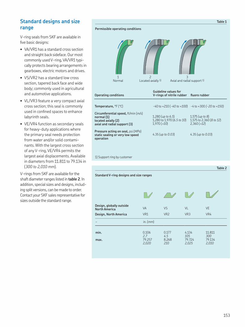
Standard designs and size range
V-ring seals from SKF are available in
ive basic designs:
• VA/VR1 has a standard cross section
and straight back sideface. Our most
commonly used V-ring, VA/VR1 typi-
cally protects bearing arrangements in
gearboxes, electric motors and drives.
• VS/VR2 has a standard low cross
section, tapered back face and wide
body; commonly used in agricultural
and automotive applications.
• VL/VR3 feature a very compact axial
cross section; this seal is commonly
used in conined spaces to enhance
labyrinth seals.
• VE/VR4 function as secondary seals
for heavy-duty applications where
the primary seal needs protection
from water and/or solid contami-
nants. With the largest cross section
of any V-ring, VE/VR4 permits the
largest axial displacements. Available
in diameters from 11.811 to 79.134 in
(300 to 2,010 mm).
V-rings from SKF are available for the
shaft diameter ranges listed in table 2. In
addition, special sizes and designs, includ-
ing split versions, can be made to order.
Contact your SKF sales representative for
sizes outside the standard range.
Table 1
Permissible operating conditions
Table 2
Standard V-ring designs and size ranges
2Located axially 1)
3Axial and radial support 1)
1) Support ring by customer
1Normal
Operating conditionsGuideline values for V-rings of nitrile rubber luoro rubber
Temperature, °F (°C) -40 to +210 (-40 to +100) -4 to +300 (-20 to +150)
Circumferential speed, ft/min (m/s)normal (1) 1,280 (up to 6.5) 1,575 (up to 8)located axially (2) 1,280 to 1,970 (6.5 to 10) 1,575 to 2,360 (8 to 12)axial and radial support (3) 1,970 (>10) 2,360 (>12)
Pressure acting on seal, psi (MPa)static sealing or very low speed operation
4.35 (up to 0.03) 4.35 (up to 0.03)
Design, globally outside North America VA VS VL VE
Design, North America VR1 VR2 VR3 VR4
– in. (mm)
min. 0.106 0.177 4.134 11.8112.7 4.5 105 300
max. 79.257 8.268 79.724 79.1342,020 210 2,025 2,010
153

V-ring seals
Applications
V-rings are suitable for both grease and oil lubricated applications. For sealing grease-lubricated bearing arrangements and protecting against contaminants, V-ring should be arranged outside the housing cover or housing wall. Dust, water spray and other contaminants can be excluded in this position († fig. ). The V-ring can also act as a grease valve, where used grease or excess new grease can escape between the housing bore and the sealing lip († fig. ). The instal-lation of two opposing V-rings can be used in applications where lubricant retention and contaminant exclusion are of equal importance († fig. ). If V-rings are used to retain oil, they should always be located axially on the shaft on the lubricant side († fig. ). V-rings should not be submerged in the application medium.
Secondary applications
V-rings are often used as secondary seals († fig. ) when it is necessary to protect the sealing lip and housing bore of the primary seal against contaminants or corrosion. V-rings will also enhance the sealing efficiency of labyrinth seals († fig. ).
Figure
V-ring used as an excluder
Figure
V-ring located axially
Figure
V-ring used as a grease valve
Figure
V-ring used as a secondary seal
Figure
Two opposing V-rings
Figure
V-rings in a labyrinth seal

Sliding velocities
V-rings can operate under the conditions listed in Table . At speeds of , to , ft/min ( to m/s), the sealing lip lifts from the counterface and the V-ring only acts as a gap-type seal.
Coaxiality and runout
The total tolerance for the deviation from coaxiality and runout should not exceed the guideline values provided in Table .
Misalignment
V-rings can tolerate misalignment between the shaft and housing, or devia-tions from the perpendicularity between the shaft and housing bore. Diagram provides values for the maximum per-missible angular misalignment; these values apply to the V-ring designs VA/VR and VS/VR, provided they are sup-ported axially on the shaft.
The permissible misalignment values for the compact VL/VR seals are signifi-cantly lower than those for the VA/VR and VS/VR designs. In applications where V-rings are not supported axially on the shaft, the maximum values form diagram should be reduced.
Table
Coaxiality and runout tolerances
Diagram
Maximum permissible misalignment for V-rings of the VA/VR and VS/VR designs
Shaft diameter Total tolerance
nominal for coaxiality deviation and runout
d Kd
over incl. over incl. max
in. mm in mm
V-rings, VA/VR and VS/VR designs. . . .
. . . . . .. . . . .. . . .
. . . .. . . .. . . .. . . .
V-rings, VL/VR designs. . . ,
V-rings, VE/VR designs. . .
Kd1
. (,)
. ()
. ()
. ()
. ()
. ()
. ()
. ()
. ()
. ()
.
Misalignment α, degrees
Shaft diameter [in. (mm)]
±α
.
.
.
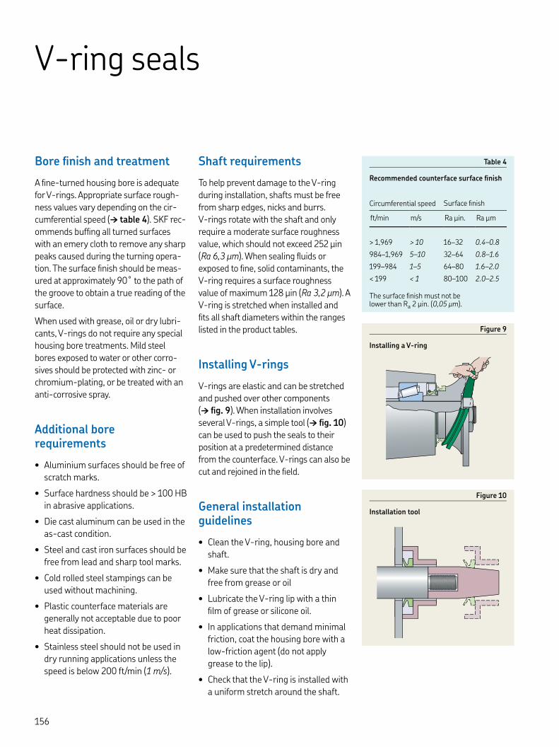
V-ring seals
Bore finish and treatment
A fine-turned housing bore is adequate for V-rings. Appropriate surface rough-ness values vary depending on the cir-cumferential speed († table ). SKF rec-ommends buffing all turned surfaces with an emery cloth to remove any sharp peaks caused during the turning opera-tion. The surface finish should be meas-ured at approximately ˚ to the path of the groove to obtain a true reading of the surface.
When used with grease, oil or dry lubri-cants, V-rings do not require any special housing bore treatments. Mild steel bores exposed to water or other corro-sives should be protected with zinc- or chromium-plating, or be treated with an anti-corrosive spray.
Additional bore requirements
• Aluminium surfaces should be free of scratch marks.
• Surface hardness should be > HB in abrasive applications.
• Die cast aluminum can be used in the as-cast condition.
• Steel and cast iron surfaces should be free from lead and sharp tool marks.
• Cold rolled steel stampings can be used without machining.
• Plastic counterface materials are generally not acceptable due to poor heat dissipation.
• Stainless steel should not be used in dry running applications unless the speed is below ft/min ( m/s).
Shaft requirements
To help prevent damage to the V-ring during installation, shafts must be free from sharp edges, nicks and burrs. V-rings rotate with the shaft and only require a moderate surface roughness value, which should not exceed μin (Ra , μm). When sealing fluids or exposed to fine, solid contaminants, the V-ring requires a surface roughness value of maximum μin (Ra , μm). A V-ring is stretched when installed and fits all shaft diameters within the ranges listed in the product tables.
Installing V-rings
V-rings are elastic and can be stretched and pushed over other components († fig. ). When installation involves several V-rings, a simple tool († fig. ) can be used to push the seals to their position at a predetermined distance from the counterface. V-rings can also be cut and rejoined in the field.
General installation guidelines
• Clean the V-ring, housing bore and shaft.
• Make sure that the shaft is dry and free from grease or oil
• Lubricate the V-ring lip with a thin film of grease or silicone oil.
• In applications that demand minimal friction, coat the housing bore with a low-friction agent (do not apply grease to the lip).
• Check that the V-ring is installed with a uniform stretch around the shaft.
Figure
Installing a V-ring
Table
Recommended counterface surface finish
Figure
Installation tool
Circumferential speed Surface finish
ft/min m/s Ra µin. Ra µm
> , > – .–.
–, – – .–.
– – – .–.
< < – .–.
The surface finish must not be lower than Ra µin. (, µm).


V-Rings Size listing
Inch
SKF Part Number
Shaft dia. min
Shaft dia. max
Free state seal ID Fitted width Max face ID Min face OD
Seal seat width Seal height
Design Mat’l d d d B D D b c
VR R . . . .±. d + . d + . . . VR V . . . .±. d + . d + . . . VR R . . . .±. d + . d + . . . VR V . . . .±. d + . d + . . . VR R . . . .±. d + . d + . . . VR V . . . .±. d + . d + . . . VR R . . . .±. d + . d + . . . VR V . . . .±. d + . d + . . . VR R . . . .±. d + . d + . . . VR V . . . .±. d + . d + . . . VR R . . . .±. d + . d + . . . VR V . . . .±. d + . d + . . . VR R . . . .±. d + . d + . . . VR V . . . .±. d + . d + . . . VR R . . . .±. d + . d + . . . VR V . . . .±. d + . d + . . . VR R . . . .±. d + . d + . . . VR V . . . .±. d + . d + . . . VR R . . . .±. d + . d + . . . VR V . . . .±. d + . d + . . . VR R . . . .±. d + . d + . . . VR V . . . .±. d + . d + . . . VR R . . . .±. d + . d + . . . VR V . . . .±. d + . d + . . . VR R . . . .±. d + . d + . . . VR V . . . .±. d + . d + . . . VR R . . . .±. d + . d + . . . VR V . . . .±. d + . d + . . . VR R . . . .±. d + . d + . . . VR V . . . .±. d + . d + . . . VR R . . . .±. d + . d + . . . VR V . . . .±. d + . d + . . . VR R . . . .±. d + . d + . . . VR V . . . .±. d + . d + . . . VR R . . . .±. d + . d + . . . VR V . . . .±. d + . d + . . . VR R . . . .±. d + . d + . . . VR V . . . .±. d + . d + . . . VR R . . . .±. d + . d + . . . VR V . . . .±. d + . d + . . . VR R . . . .±. d + . d + . . . VR V . . . .±. d + . d + . . . VR R . . . .±. d + . d + . . . VR V . . . .±. d + . d + . . . VR R . . . .±. d + . d + . . . VR V . . . .±. d + . d + . . . VR R . . . .±. d + . d + . . . VR V . . . .±. d + . d + . . .
b1
B1
d1 D
c
d D1

Key features: ▲ WasteWatcher ■ Bore-Tite ◤ SS Case ◎ SS Spring ◆ Pressure seal up to 50 psi ◇ Cover plate required
V-Rings Size listing
Metric (mm)
Shaft dia. min
Shaft dia. max
Free state seal ID Fitted width Max face ID Min face OD
Seal seat width Seal height SKF Part
Numberd d d B D D b c
. . . .±. d + d + . . . . . .±. d + d + . . . . . ±. d + d + . . . . ±. d + d + . . . ±. d + d + . . . ±. d + d + . . . .±. d + d + . . . .±. d + d + . . . ±. d + d + . . . ±. d + d + . . . .±. d + d + . . . .±. d + d + . . ±. d + d + . . ±. d + d + . . .±. d + d + . . .±. d + d + . . ±. d + d + . . ±. d + d + . . .±. d + d + . . .±. d + d + . . . .±. d + d + . . . .±. d + d + . . . .±. d + d + . . . .±. d + d + . . . . .±. d + d + . . . . .±. d + d + . . . . .±. d + d + . . . . .±. d + d + . . . . .±. d + d + . . . . .±. d + d + . . . . .±. d + d + . . . . .±. d + d + . . . . .±. d + d + . . . . .±. d + d + . . . .±. d + d + . . . .±. d + d + . . . .±. d + d + . . . .±. d + d + . . .±. d + d + . . .±. d + d + . . .±. d + d + . . .±. d + d + . ±. d + d + . ±. d + d + . ±. d + d + . ±. d + d + . ±. d + d + . ±. d + d + .
b1
B1
d1 D
c
d D1
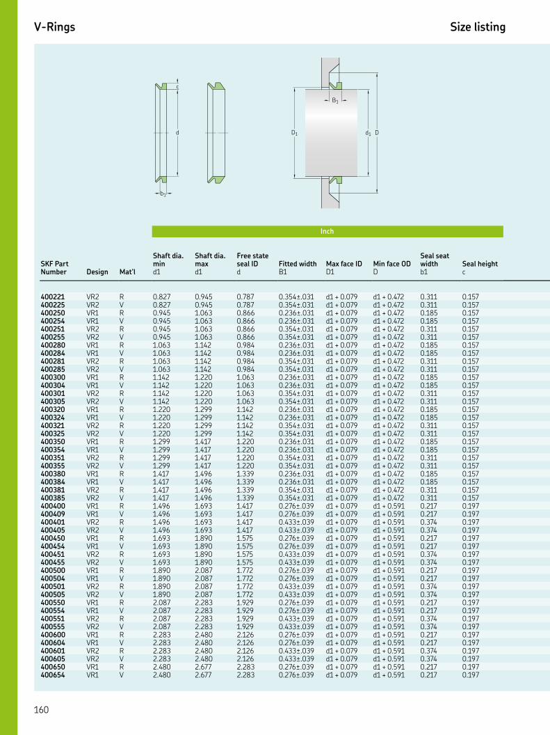
V-Rings Size listing
Inch
SKF Part Number
Shaft dia. min
Shaft dia. max
Free state seal ID Fitted width Max face ID Min face OD
Seal seat width Seal height
Design Mat’l d d d B D D b c
VR R . . . .±. d + . d + . . . VR V . . . .±. d + . d + . . . VR R . . . .±. d + . d + . . . VR V . . . .±. d + . d + . . . VR R . . . .±. d + . d + . . . VR V . . . .±. d + . d + . . . VR R . . . .±. d + . d + . . . VR V . . . .±. d + . d + . . . VR R . . . .±. d + . d + . . . VR V . . . .±. d + . d + . . . VR R . . . .±. d + . d + . . . VR V . . . .±. d + . d + . . . VR R . . . .±. d + . d + . . . VR V . . . .±. d + . d + . . . VR R . . . .±. d + . d + . . . VR V . . . .±. d + . d + . . . VR R . . . .±. d + . d + . . . VR V . . . .±. d + . d + . . . VR R . . . .±. d + . d + . . . VR V . . . .±. d + . d + . . . VR R . . . .±. d + . d + . . . VR V . . . .±. d + . d + . . . VR R . . . .±. d + . d + . . . VR V . . . .±. d + . d + . . . VR R . . . .±. d + . d + . . . VR V . . . .±. d + . d + . . . VR R . . . .±. d + . d + . . . VR V . . . .±. d + . d + . . . VR R . . . .±. d + . d + . . . VR V . . . .±. d + . d + . . . VR R . . . .±. d + . d + . . . VR V . . . .±. d + . d + . . . VR R . . . .±. d + . d + . . . VR V . . . .±. d + . d + . . . VR R . . . .±. d + . d + . . . VR V . . . .±. d + . d + . . . VR R . . . .±. d + . d + . . . VR V . . . .±. d + . d + . . . VR R . . . .±. d + . d + . . . VR V . . . .±. d + . d + . . . VR R . . . .±. d + . d + . . . VR V . . . .±. d + . d + . . . VR R . . . .±. d + . d + . . . VR V . . . .±. d + . d + . . . VR R . . . .±. d + . d + . . . VR V . . . .±. d + . d + . . . VR R . . . .±. d + . d + . . . VR V . . . .±. d + . d + . . .
b1
B1
d1 D
c
d D1

Key features: ▲ WasteWatcher ■ Bore-Tite ◤ SS Case ◎ SS Spring ◆ Pressure seal up to 50 psi ◇ Cover plate required
V-Rings Size listing
Metric (mm)
Shaft dia. min
Shaft dia. max
Free state seal ID Fitted width Max face ID Min face OD
Seal seat width Seal height SKF Part
Numberd d d B D D b c
±. d + d + . ±. d + d + . ±. d + d + . ±. d + d + . ±. d + d + . ±. d + d + . ±. d + d + . ±. d + d + . ±. d + d + . ±. d + d + . ±. d + d + . ±. d + d + . ±. d + d + . ±. d + d + . ±. d + d + . ±. d + d + . ±. d + d + . ±. d + d + . ±. d + d + . ±. d + d + . ±. d + d + . ±. d + d + . ±. d + d + . ±. d + d + . ±. d + d + . ±. d + d + . ± d + d + . ± d + d + . ± d + d + . ± d + d + . ± d + d + . ± d + d + . ± d + d + . ± d + d + . ± d + d + . ± d + d + . ± d + d + . ± d + d + . ± d + d + . ± d + d + . ± d + d + . ± d + d + . ± d + d + . ± d + d + . ± d + d + . ± d + d + . ± d + d + . ± d + d + .
b1
B1
d1 D
c
d D1

V-Rings Size listing
Inch
SKF Part Number
Shaft dia. min
Shaft dia. max
Free state seal ID Fitted width Max face ID Min face OD
Seal seat width Seal height
Design Mat’l d d d B D D b c
VR R . . . .±. d + . d + . . . VR V . . . .±. d + . d + . . . VR R . . . .±. d + . d + . . . VR V . . . .±. d + . d + . . . VR R . . . .±. d + . d + . . . VR V . . . .±. d + . d + . . . VR R . . . .±. d + . d + . . . VR V . . . .±. d + . d + . . . VR R . . . .±. d + . d + . . . VR V . . . .±. d + . d + . . . VR R . . . .±. d + . d + . . . VR V . . . .±. d + . d + . . . VR R . . . .±. d + . d + . . . VR V . . . .±. d + . d + . . . VR R . . . .±. d + . d + . . . VR V . . . .±. d + . d + . . . VR R . . . .±. d + . d + . . . VR V . . . .±. d + . d + . . . VR R . . . .±. d + . d + . . . VR V . . . .±. d + . d + . . . VR R . . . .±. d + . d + . . . VR V . . . .±. d + . d + . . . VR R . . . .±. d + . d + . . . VR V . . . .±. d + . d + . . . VR R . . . .±. d + . d + . . . VR V . . . .±. d + . d + . . . VR R . . . .±. d + . d + . . . VR V . . . .±. d + . d + . . . VR R . . . .±. d + . d + . . . VR V . . . .±. d + . d + . . . VR R . . . .±. d + . d + . . . VR V . . . .±. d + . d + . . . VR R . . . .±. d + . d + . . . VR V . . . .±. d + . d + . . . VR R . . . .±. d + . d + . . . VR V . . . .±. d + . d + . . . VR R . . . .±. d + . d + . . . VR V . . . .±. d + . d + . . . VR R . . . .±. d + . d + . . . VR V . . . .±. d + . d + . . . VR R . . . .±. d + . d + . . . VR V . . . .±. d + . d + . . . VR V . . . .±. d + . d + . . . VR R . . . .±. d + . d + . . . VR V . . . .±. d + . d + . . . VR R . . . .±. d + . d + . . . VR V . . . .±. d + . d + . . .
b1
B1
d1 D
c
d D1
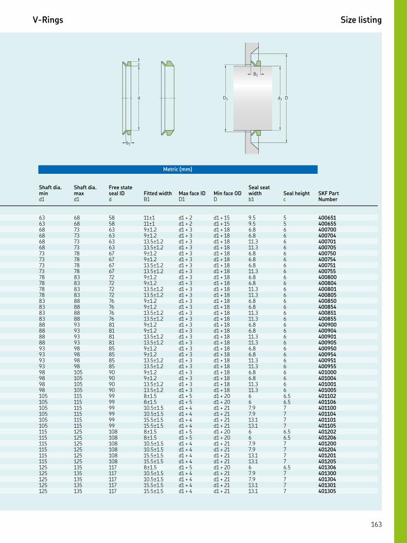
Key features: ▲ WasteWatcher ■ Bore-Tite ◤ SS Case ◎ SS Spring ◆ Pressure seal up to 50 psi ◇ Cover plate required
V-Rings Size listing
Metric (mm)
Shaft dia. min
Shaft dia. max
Free state seal ID Fitted width Max face ID Min face OD
Seal seat width Seal height SKF Part
Numberd d d B D D b c
± d + d + . ± d + d + . ±. d + d + . ±. d + d + . .±. d + d + . .±. d + d + . ±. d + d + . ±. d + d + . .±. d + d + . .±. d + d + . ±. d + d + . ±. d + d + . .±. d + d + . .±. d + d + . ±. d + d + . ±. d + d + . .±. d + d + . .±. d + d + . ±. d + d + . ±. d + d + . .±. d + d + . .±. d + d + . ±. d + d + . ±. d + d + . .±. d + d + . .±. d + d + . ±. d + d + . ±. d + d + . .±. d + d + . .±. d + d + . ±. d + d + . ±. d + d + . .±. d + d + . .±. d + d + . .±. d + d + . .±. d + d + . ±. d + d + . ±. d + d + . .±. d + d + . .±. d + d + . .±. d + d + . .±. d + d + . ±. d + d + . .±. d + d + . .±. d + d + . .±. d + d + . .±. d + d + .
b1
B1
d1 D
c
d D1

V-Rings Size listing
Inch
SKF Part Number
Shaft dia. min
Shaft dia. max
Free state seal ID Fitted width Max face ID Min face OD
Seal seat width Seal height
Design Mat’l d d d B D D b c
VR R . . . .±. d + . d + . . . VR V . . . .±. d + . d + . . . VR R . . . .±. d + . d + . . . VR V . . . .±. d + . d + . . . VR R . . . .±. d + . d + . . . VR V . . . .±. d + . d + . . . VR R . . . .±. d + . d + . . . VR V . . . .±. d + . d + . . . VR R . . . .±. d + . d + . . . VR V . . . .±. d + . d + . . . VR R . . . .±. d + . d + . . . VR V . . . .±. d + . d + . . . VR R . . . .±. d + . d + . . . VR V . . . .±. d + . d + . . . VR R . . . .±. d + . d + . . . VR V . . . .±. d + . d + . . . VR R . . . .±. d + . d + . . . VR V . . . .±. d + . d + . . . VR R . . . .±. d + . d + . . . VR V . . . .±. d + . d + . . . VR R . . . .±. d + . d + . . . VR V . . . .±. d + . d + . . . VR R . . . .±. d + . d + . . . VR V . . . .±. d + . d + . . . VR R . . . .±. d + . d + . . . VR V . . . .±. d + . d + . . . VR R . . . .±. d + . d + . . . VR V . . . .±. d + . d + . . . VR R . . . .±. d + . d + . . . VR V . . . .±. d + . d + . . . VR R . . . .±. d + . d + . . . VR V . . . .±. d + . d + . . . VR R . . . .±. d + . d + . . . VR V . . . .±. d + . d + . . . VR R . . . .±. d + . d + . . . VR V . . . .±. d + . d + . . . VR R . . . .±. d + . d + . . . VR V . . . .±. d + . d + . . . VR R . . . .±. d + . d + . . . VR V . . . .±. d + . d + . . . VR R . . . .±. d + . d + . . . VR V . . . .±. d + . d + . . . VR R . . . .±. d + . d + . . . VR V . . . .±. d + . d + . . . VR R . . . .±. d + . d + . . . VR V . . . .±. d + . d + . . . VR R . . . .±. d + . d + . . . VR V . . . .±. d + . d + . . .
b1
B1
d1 D
c
d D1

Key features: ▲ WasteWatcher ■ Bore-Tite ◤ SS Case ◎ SS Spring ◆ Pressure seal up to 50 psi ◇ Cover plate required
V-Rings Size listing
Metric (mm)
Shaft dia. min
Shaft dia. max
Free state seal ID Fitted width Max face ID Min face OD
Seal seat width Seal height SKF Part
Numberd d d B D D b c
±. d + d + . ±. d + d + . .±. d + d + . .±. d + d + . .±. d + d + . .±. d + d + . ±. d + d + . ±. d + d + . .±. d + d + . .±. d + d + . .±. d + d + . .±. d + d + . ±. d + d + . ±. d + d + . ±. d + d + ±. d + d + ±. d + d + ±. d + d + ±. d + d + . ±. d + d + . ±. d + d + ±. d + d + ±. d + d + ±. d + d + ±. d + d + . ±. d + d + . ±. d + d + ±. d + d + ±. d + d + ±. d + d + ±. d + d + . ±. d + d + . ±. d + d + ±. d + d + ±. d + d + ±. d + d + ±. d + d + . ±. d + d + . ±. d + d + ±. d + d + ±. d + d + ±. d + d + ± d + d + . ± d + d + . ±. d + d + . ±. d + d + . ± d + d + . ± d + d + .
b1
B1
d1 D
c
d D1

V-Rings Size listing
Inch
SKF Part Number
Shaft dia. min
Shaft dia. max
Free state seal ID Fitted width Max face ID Min face OD
Seal seat width Seal height
Design Mat’l d d d B D D b c
VR R . . . .±. d + . d + . . . VR V . . . .±. d + . d + . . . VR R . . . .±. d + . d + . . . VR V . . . .±. d + . d + . . . VR R . . . .±. d + . d + . . . VR V . . . .±. d + . d + . . . VR R . . . .±. d + . d + . . . VR V . . . .±. d + . d + . . . VR R . . . .±. d + . d + . . . VR V . . . .±. d + . d + . . . VR R . . . .±. d + . d + . . . VR V . . . .±. d + . d + . . . VR R . . . .±. d + . d + . . . VR R . . . .±. d + . d + . . . VR R . . . .±. d + . d + . . . VR V . . . .±. d + . d + . . . VR R . . . .±. d + . d + . . . VR V . . . .±. d + . d + . . . VR R . . . .±. d + . d + . . . VR R . . . .±. d + . d + . . . VR R . . . .±. d + . d + . . . VR R . . . .±. d + . d + . . . VR R . . . .±. d + . d + . . . VR R . . . .±. d + . d + . . . VR V . . . .±. d + . d + . . . VR R . . . .±. d + . d + . . . VR V . . . .±. d + . d + . . . VR R . . . .±. d + . d + . . . VR R . . . .±. d + . d + . . . VR R . . . .±. d + . d + . . . VR R . . . .±. d + . d + . . . VR R . . . .±. d + . d + . . . VR R . . . .±. d + . d + . . . VR R . . . .±. d + . d + . . . VR V . . . .±. d + . d + . . . VR R . . . .±. d + . d + . . . VR V . . . .±. d + . d + . . . VR R . . . .±. d + . d + . . . VR R . . . .±. d + . d + . . . VR R . . . .±. d + . d + . . . VR R . . . .±. d + . d + . . . VR R . . . .±. d + . d + . . . VR V . . . .±. d + . d + . . . VR R . . . .±. d + . d + . . . VR R . . . .±. d + . d + . . . VR V . . . .±. d + . d + . . . VR R . . . .±. d + . d + . . . VR R . . . .±. d + . d + . . .
b1
B1
d1 D
c
d D1

Key features: ▲ WasteWatcher ■ Bore-Tite ◤ SS Case ◎ SS Spring ◆ Pressure seal up to 50 psi ◇ Cover plate required
V-Rings Size listing
Metric (mm)
Shaft dia. min
Shaft dia. max
Free state seal ID Fitted width Max face ID Min face OD
Seal seat width Seal height SKF Part
Numberd d d B D D b c
±. d + d + . ±. d + d + . ± d + d + . ± d + d + . ±. d + d + . ±. d + d + . ± d + d + . ± d + d + . ±. d + d + . ±. d + d + . ± d + d + . ± d + d + . ± d + d + . ± d + d + . ±. d + d + . ±. d + d + . ± d + d + . ± d + d + . ± d + d + . ± d + d + . ± d + d + . ± d + d + . ± d + d + . ±. d + d + . ±. d + d + . ± d + d + . ± d + d + . ± d + d + . ± d + d + . ± d + d + . ± d + d + . ± d + d + . ± d + d + . ±. d + d + . ±. d + d + . ± d + d + . ± d + d + . ± d + d + . ± d + d + . ± d + d + . ± d + d + . ±. d + d + . ±. d + d + . ± d + d + . ± d + d + . ± d + d + . ± d + d + . ± d + d + .
b1
B1
d1 D
c
d D1
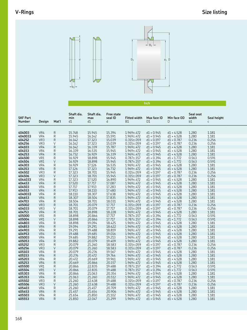
V-Rings Size listing
Inch
SKF Part Number
Shaft dia. min
Shaft dia. max
Free state seal ID Fitted width Max face ID Min face OD
Seal seat width Seal height
Design Mat’l d d d B D D b c
VR R . . . .±. d + . d + . . . VR R . . . .±. d + . d + . . . VR R . . . .±. d + . d + . . . VR V . . . .±. d + . d + . . . VR R . . . .±. d + . d + . . . VR R . . . .±. d + . d + . . . VR R . . . .±. d + . d + . . . VR R . . . .±. d + . d + . . . VR V . . . .±. d + . d + . . . VR R . . . .±. d + . d + . . . VR R . . . .±. d + . d + . . . VR R . . . .±. d + . d + . . . VR V . . . .±. d + . d + . . . VR R . . . .±. d + . d + . . . VR R . . . .±. d + . d + . . . VR R . . . .±. d + . d + . . . VR R . . . .±. d + . d + . . . VR R . . . .±. d + . d + . . . VR R . . . .±. d + . d + . . . VR R . . . .±. d + . d + . . . VR R . . . .±. d + . d + . . . VR V . . . .±. d + . d + . . . VR R . . . .±. d + . d + . . . VR R . . . .±. d + . d + . . . VR V . . . .±. d + . d + . . . VR R . . . .±. d + . d + . . . VR R . . . .±. d + . d + . . . VR R . . . .±. d + . d + . . . VR R . . . .±. d + . d + . . . VR R . . . .±. d + . d + . . . VR R . . . .±. d + . d + . . . VR R . . . .±. d + . d + . . . VR V . . . .±. d + . d + . . . VR R . . . .±. d + . d + . . . VR R . . . .±. d + . d + . . . VR R . . . .±. d + . d + . . . VR R . . . .±. d + . d + . . . VR R . . . .±. d + . d + . . . VR V . . . .±. d + . d + . . . VR R . . . .±. d + . d + . . . VR R . . . .±. d + . d + . . . VR R . . . .±. d + . d + . . . VR V . . . .±. d + . d + . . . VR R . . . .±. d + . d + . . . VR R . . . .±. d + . d + . . . VR R . . . .±. d + . d + . . . VR R . . . .±. d + . d + . . .
b1
B1
d1 D
c
d D1
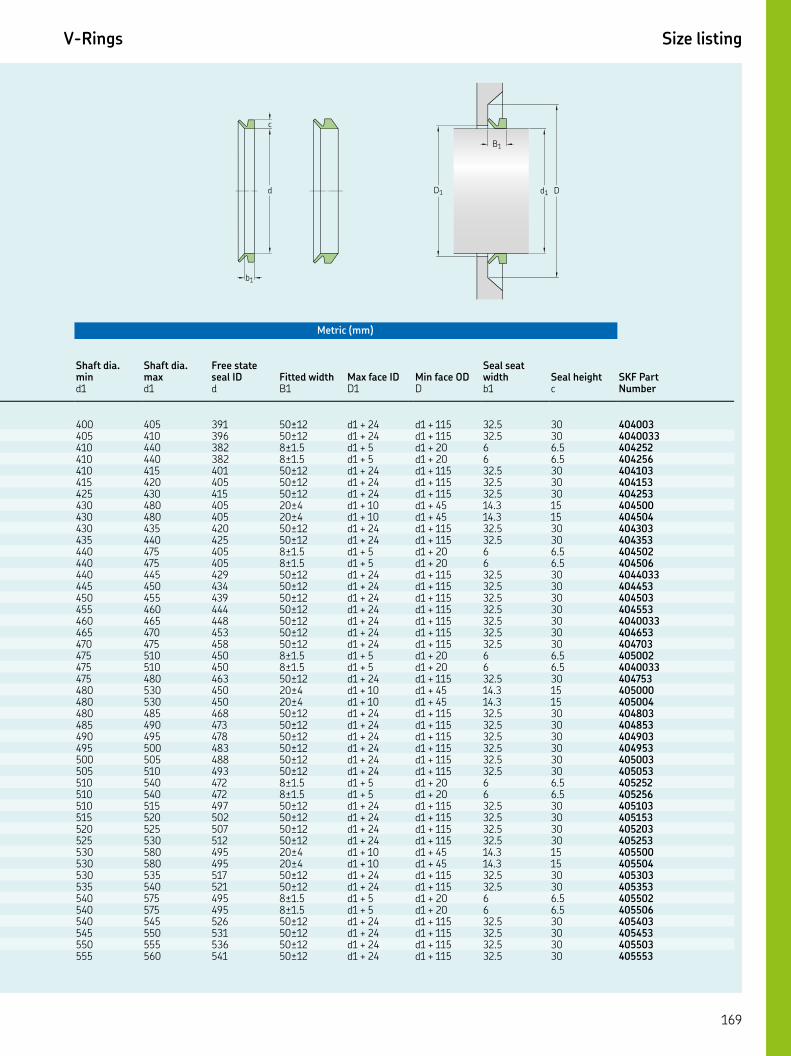
Key features: ▲ WasteWatcher ■ Bore-Tite ◤ SS Case ◎ SS Spring ◆ Pressure seal up to 50 psi ◇ Cover plate required
V-Rings Size listing
Metric (mm)
Shaft dia. min
Shaft dia. max
Free state seal ID Fitted width Max face ID Min face OD
Seal seat width Seal height SKF Part
Numberd d d B D D b c
± d + d + . ± d + d + . ±. d + d + . ±. d + d + . ± d + d + . ± d + d + . ± d + d + . ± d + d + . ± d + d + . ± d + d + . ± d + d + . ±. d + d + . ±. d + d + . ± d + d + . ± d + d + . ± d + d + . ± d + d + . ± d + d + . ± d + d + . ± d + d + . ±. d + d + . ±. d + d + . ± d + d + . ± d + d + . ± d + d + . ± d + d + . ± d + d + . ± d + d + . ± d + d + . ± d + d + . ± d + d + . ±. d + d + . ±. d + d + . ± d + d + . ± d + d + . ± d + d + . ± d + d + . ± d + d + . ± d + d + . ± d + d + . ± d + d + . ±. d + d + . ±. d + d + . ± d + d + . ± d + d + . ± d + d + . ± d + d + .
b1
B1
d1 D
c
d D1

V-Rings Size listing
Inch
SKF Part Number
Shaft dia. min
Shaft dia. max
Free state seal ID Fitted width Max face ID Min face OD
Seal seat width Seal height
Design Mat’l d d d B D D b c
VR R . . . .±. d + . d + . . . VR R . . . .±. d + . d + . . . VR R . . . .±. d + . d + . . . VR R . . . .±. d + . d + . . . VR V . . . .±. d + . d + . . . VR R . . . .±. d + . d + . . . VR R . . . .±. d + . d + . . . VR V . . . .±. d + . d + . . . VR R . . . .±. d + . d + . . . VR R . . . .±. d + . d + . . . VR R . . . .±. d + . d + . . . VR R . . . .±. d + . d + . . . VR R . . . .±. d + . d + . . . VR R . . . .±. d + . d + . . . VR V . . . .±. d + . d + . . . VR R . . . .±. d + . d + . . . VR R . . . .±. d + . d + . . . VR V . . . .±. d + . d + . . . VR R . . . .±. d + . d + . . . VR R . . . .±. d + . d + . . . VR R . . . .±. d + . d + . . . VR R . . . .±. d + . d + . . . VR R . . . .±. d + . d + . . . VR V . . . .±. d + . d + . . . VR R . . . .±. d + . d + . . . VR R . . . .±. d + . d + . . . VR V . . . .±. d + . d + . . . VR R . . . .±. d + . d + . . . VR R . . . .±. d + . d + . . . VR R . . . .±. d + . d + . . . VR R . . . .±. d + . d + . . . VR V . . . .±. d + . d + . . . VR R . . . .±. d + . d + . . . VR V . . . .±. d + . d + . . . VR R . . . .±. d + . d + . . . VR R . . . .±. d + . d + . . . VR R . . . .±. d + . d + . . . VR R . . . .±. d + . d + . . . VR V . . . .±. d + . d + . . . VR R . . . .±. d + . d + . . . VR R . . . .±. d + . d + . . . VR V . . . .±. d + . d + . . . VR R . . . .±. d + . d + . . . VR R . . . .±. d + . d + . . . VR R . . . .±. d + . d + . . . VR R . . . .±. d + . d + . . . VR R . . . .±. d + . d + . . . VR V . . . .±. d + . d + . . .
b1
B1
d1 D
c
d D1

Key features: ▲ WasteWatcher ■ Bore-Tite ◤ SS Case ◎ SS Spring ◆ Pressure seal up to 50 psi ◇ Cover plate required
V-Rings Size listing
Metric (mm)
Shaft dia. min
Shaft dia. max
Free state seal ID Fitted width Max face ID Min face OD
Seal seat width Seal height SKF Part
Numberd d d B D D b c
± d + d + . ± d + d + . ± d + d + . ±. d + d + . ±. d + d + . ± d + d + . ± d + d + . ± d + d + . ± d + d + . ± d + d + . ± d + d + . ± d + d + . ± d + d + . ±. d + d + . ±. d + d + . ± d + d + . ± d + d + . ± d + d + . ± d + d + . ± d + d + . ± d + d + . ± d + d + . ± d + d + . ± d + d + . ± d + d + . ±. d + d + . ±. d + d + . ± d + d + . ± d + d + . ± d + d + . ± d + d + . ± d + d + . ±. d + d + . ±. d + d + . ± d + d + . ± d + d + . ± d + d + . ±. d + d + . ±. d + d + . ± d + d + . ± d + d + . ± d + d + . ± d + d + . ± d + d + . ± d + d + . ± d + d + . ±. d + d + . ±. d + d + .
b1
B1
d1 D
c
d D1

V-Rings Size listing
Inch
SKF Part Number
Shaft dia. min
Shaft dia. max
Free state seal ID Fitted width Max face ID Min face OD
Seal seat width Seal height
Design Mat’l d d d B D D b c
VR R . . . .±. d + . d + . . . VR R . . . .±. d + . d + . . . VR V . . . .±. d + . d + . . . VR R . . . .±. d + . d + . . . VR R . . . .±. d + . d + . . . VR R . . . .±. d + . d + . . . VR R . . . .±. d + . d + . . . VR R . . . .±. d + . d + . . . VR V . . . .±. d + . d + . . . VR R . . . .±. d + . d + . . . VR V . . . .±. d + . d + . . . VR R . . . .±. d + . d + . . . VR R . . . .±. d + . d + . . . VR R . . . .±. d + . d + . . . VR R . . . .±. d + . d + . . . VR R . . . .±. d + . d + . . . VR R . . . .±. d + . d + . . . VR V . . . .±. d + . d + . . . VR R . . . .±. d + . d + . . . VR V . . . .±. d + . d + . . . VR R . . . .±. d + . d + . . . VR R . . . .±. d + . d + . . . VR R . . . .±. d + . d + . . . VR R . . . .±. d + . d + . . . VR V . . . .±. d + . d + . . . VR R . . . .±. d + . d + . . . VR R . . . .±. d + . d + . . . VR V . . . .±. d + . d + . . . VR R . . . .±. d + . d + . . . VR R . . . .±. d + . d + . . . VR R . . . .±. d + . d + . . . VR R . . . .±. d + . d + . . . VR V . . . .±. d + . d + . . . VR R . . . .±. d + . d + . . . VR R . . . .±. d + . d + . . . VR V . . . .±. d + . d + . . . VR R . . . .±. d + . d + . . . VR R . . . .±. d + . d + . . . VR R . . . .±. d + . d + . . . VR R . . . .±. d + . d + . . . VR R . . . .±. d + . d + . . . VR R . . . .±. d + . d + . . . VR V . . . .±. d + . d + . . . VR R . . . .±. d + . d + . . . VR R . . . .±. d + . d + . . . VR R . . . .±. d + . d + . . . VR R . . . .±. d + . d + . . . VR R . . . .±. d + . d + . . .
b1
B1
d1 D
c
d D1
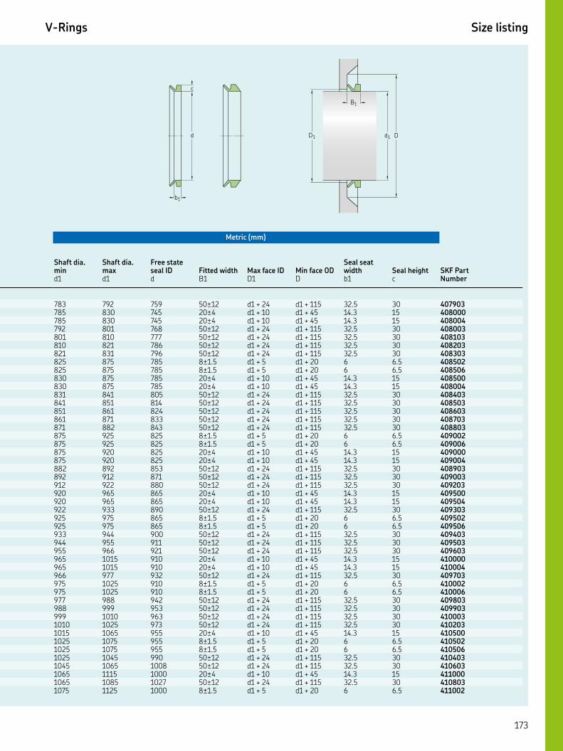
Key features: ▲ WasteWatcher ■ Bore-Tite ◤ SS Case ◎ SS Spring ◆ Pressure seal up to 50 psi ◇ Cover plate required
V-Rings Size listing
Metric (mm)
Shaft dia. min
Shaft dia. max
Free state seal ID Fitted width Max face ID Min face OD
Seal seat width Seal height SKF Part
Numberd d d B D D b c
± d + d + . ± d + d + . ± d + d + . ± d + d + . ± d + d + . ± d + d + . ± d + d + . ±. d + d + . ±. d + d + . ± d + d + . ± d + d + . ± d + d + . ± d + d + . ± d + d + . ± d + d + . ± d + d + . ±. d + d + . ±. d + d + . ± d + d + . ± d + d + . ± d + d + . ± d + d + . ± d + d + . ± d + d + . ± d + d + . ± d + d + . ±. d + d + . ±. d + d + . ± d + d + . ± d + d + . ± d + d + . ± d + d + . ± d + d + . ± d + d + . ±. d + d + . ±. d + d + . ± d + d + . ± d + d + . ± d + d + . ± d + d + . ± d + d + . ±. d + d + . ±. d + d + . ± d + d + . ± d + d + . ± d + d + . ± d + d + . ±. d + d + .
b1
B1
d1 D
c
d D1
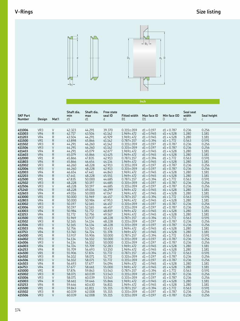
V-Rings Size listing
Inch
SKF Part Number
Shaft dia. min
Shaft dia. max
Free state seal ID Fitted width Max face ID Min face OD
Seal seat width Seal height
Design Mat’l d d d B D D b c
VR V . . . .±. d + . d + . . . VR R . . . .±. d + . d + . . . VR R . . . .±. d + . d + . . . VR R . . . .±. d + . d + . . . VR R . . . .±. d + . d + . . . VR V . . . .±. d + . d + . . . VR R . . . .±. d + . d + . . . VR R . . . .±. d + . d + . . . VR R . . . .±. d + . d + . . . VR R . . . .±. d + . d + . . . VR R . . . .±. d + . d + . . . VR V . . . .±. d + . d + . . . VR R . . . .±. d + . d + . . . VR R . . . .±. d + . d + . . . VR R . . . .±. d + . d + . . . VR R . . . .±. d + . d + . . . VR V . . . .±. d + . d + . . . VR R . . . .±. d + . d + . . . VR R . . . .±. d + . d + . . . VR R . . . .±. d + . d + . . . VR R . . . .±. d + . d + . . . VR R . . . .±. d + . d + . . . VR V . . . .±. d + . d + . . . VR R . . . .±. d + . d + . . . VR R . . . .±. d + . d + . . . VR R . . . .±. d + . d + . . . VR R . . . .±. d + . d + . . . VR V . . . .±. d + . d + . . . VR R . . . .±. d + . d + . . . VR R . . . .±. d + . d + . . . VR R . . . .±. d + . d + . . . VR R . . . .±. d + . d + . . . VR V . . . .±. d + . d + . . . VR R . . . .±. d + . d + . . . VR R . . . .±. d + . d + . . . VR R . . . .±. d + . d + . . . VR R . . . .±. d + . d + . . . VR V . . . .±. d + . d + . . . VR R . . . .±. d + . d + . . . VR R . . . .±. d + . d + . . . VR R . . . .±. d + . d + . . . VR R . . . .±. d + . d + . . . VR V . . . .±. d + . d + . . . VR R . . . .±. d + . d + . . . VR R . . . .±. d + . d + . . . VR R . . . .±. d + . d + . . . VR R . . . .±. d + . d + . . . VR V . . . .±. d + . d + . . .
b1
B1
d1 D
c
d D1
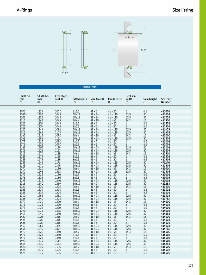
Key features: ▲ WasteWatcher ■ Bore-Tite ◤ SS Case ◎ SS Spring ◆ Pressure seal up to 50 psi ◇ Cover plate required
V-Rings Size listing
Metric (mm)
Shaft dia. min
Shaft dia. max
Free state seal ID Fitted width Max face ID Min face OD
Seal seat width Seal height SKF Part
Numberd d d B D D b c
±. d + d + . ± d + d + . ± d + d + . ± d + d + . ±. d + d + . ±. d + d + . ± d + d + . ± d + d + . ± d + d + . ± d + d + . ±. d + d + . ±. d + d + . ± d + d + . ± d + d + . ± d + d + . ±. d + d + . ±. d + d + . ± d + d + . ± d + d + . ± d + d + . ± d + d + . ±. d + d + . ±. d + d + . ± d + d + . ± d + d + . ± d + d + . ±. d + d + . ±. d + d + . ± d + d + . ± d + d + . ± d + d + . ±. d + d + . ±. d + d + . ± d + d + . ± d + d + . ± d + d + . ±. d + d + . ±. d + d + . ± d + d + . ± d + d + . ± d + d + . ±. d + d + . ±. d + d + . ± d + d + . ± d + d + . ± d + d + . ±. d + d + . ±. d + d + .
b1
B1
d1 D
c
d D1
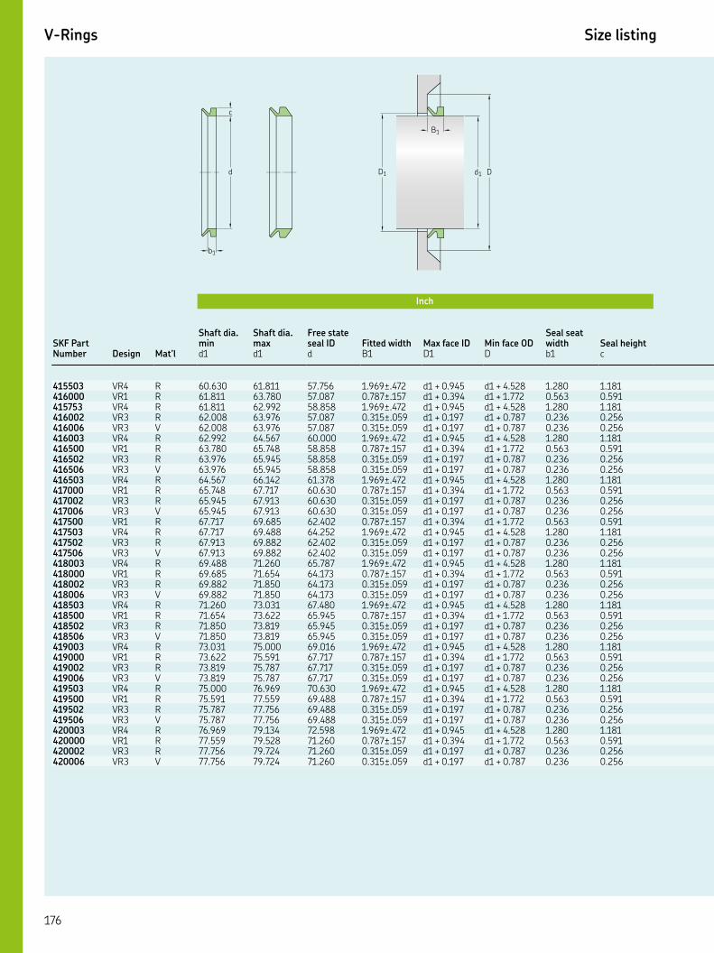
V-Rings Size listing
Inch
SKF Part Number
Shaft dia. min
Shaft dia. max
Free state seal ID Fitted width Max face ID Min face OD
Seal seat width Seal height
Design Mat’l d d d B D D b c
VR R . . . .±. d + . d + . . . VR R . . . .±. d + . d + . . . VR R . . . .±. d + . d + . . . VR R . . . .±. d + . d + . . . VR V . . . .±. d + . d + . . . VR R . . . .±. d + . d + . . . VR R . . . .±. d + . d + . . . VR R . . . .±. d + . d + . . . VR V . . . .±. d + . d + . . . VR R . . . .±. d + . d + . . . VR R . . . .±. d + . d + . . . VR R . . . .±. d + . d + . . . VR V . . . .±. d + . d + . . . VR R . . . .±. d + . d + . . . VR R . . . .±. d + . d + . . . VR R . . . .±. d + . d + . . . VR V . . . .±. d + . d + . . . VR R . . . .±. d + . d + . . . VR R . . . .±. d + . d + . . . VR R . . . .±. d + . d + . . . VR V . . . .±. d + . d + . . . VR R . . . .±. d + . d + . . . VR R . . . .±. d + . d + . . . VR R . . . .±. d + . d + . . . VR V . . . .±. d + . d + . . . VR R . . . .±. d + . d + . . . VR R . . . .±. d + . d + . . . VR R . . . .±. d + . d + . . . VR V . . . .±. d + . d + . . . VR R . . . .±. d + . d + . . . VR R . . . .±. d + . d + . . . VR R . . . .±. d + . d + . . . VR V . . . .±. d + . d + . . . VR R . . . .±. d + . d + . . . VR R . . . .±. d + . d + . . . VR R . . . .±. d + . d + . . . VR V . . . .±. d + . d + . . .
b1
B1
d1 D
c
d D1

Key features: ▲ WasteWatcher ■ Bore-Tite ◤ SS Case ◎ SS Spring ◆ Pressure seal up to 50 psi ◇ Cover plate required
V-Rings Size listing
Metric (mm)
Shaft dia. min
Shaft dia. max
Free state seal ID Fitted width Max face ID Min face OD
Seal seat width Seal height SKF Part
Numberd d d B D D b c
± d + d + . ± d + d + . ± d + d + . ±. d + d + . ±. d + d + . ± d + d + . ± d + d + . ±. d + d + . ±. d + d + . ± d + d + . ± d + d + . ±. d + d + . ±. d + d + . ± d + d + . ± d + d + . ±. d + d + . ±. d + d + . ± d + d + . ± d + d + . ±. d + d + . ±. d + d + . ± d + d + . ± d + d + . ±. d + d + . ±. d + d + . ± d + d + . ± d + d + . ±. d + d + . ±. d + d + . ± d + d + . ± d + d + . ±. d + d + . ±. d + d + . ± d + d + . ± d + d + . ±. d + d + . ±. d + d + .
b1
B1
d1 D
c
d D1
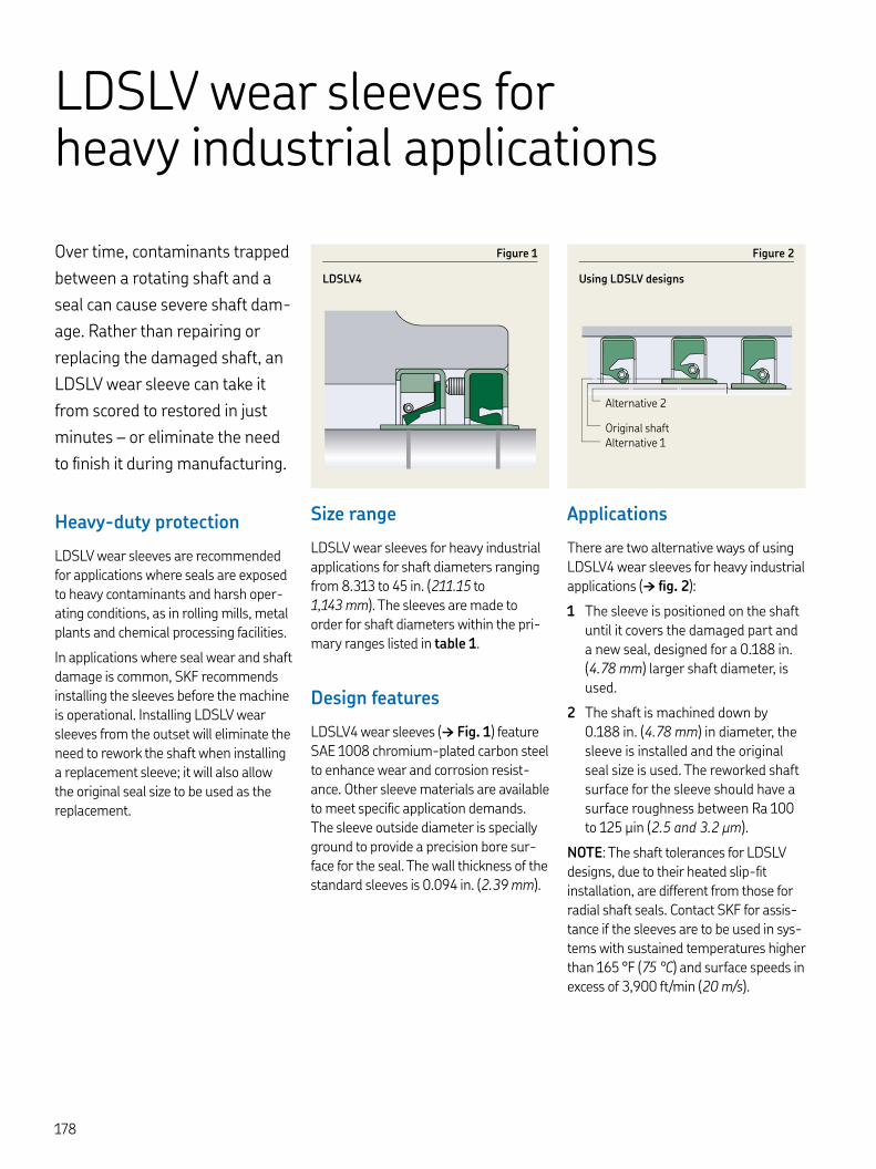
LDSLV wear sleeves for heavy industrial applications
Over time, contaminants trapped
between a rotating shaft and a
seal can cause severe shaft dam-
age. Rather than repairing or
replacing the damaged shaft, an
LDSLV wear sleeve can take it
from scored to restored in just
minutes – or eliminate the need
to finish it during manufacturing.
Heavy-duty protection
LDSLV wear sleeves are recommended for applications where seals are exposed to heavy contaminants and harsh oper-ating conditions, as in rolling mills, metal plants and chemical processing facilities.
In applications where seal wear and shaft damage is common, SKF recommends installing the sleeves before the machine is operational. Installing LDSLV wear sleeves from the outset will eliminate the need to rework the shaft when installing a replacement sleeve; it will also allow the original seal size to be used as the replacement.
Figure
LDSLV
Figure
Using LDSLV designs
Alternative
Original shaftAlternative
Size range
LDSLV wear sleeves for heavy industrial applications for shaft diameters ranging from . to in. (. to , mm). The sleeves are made to order for shaft diameters within the pri-mary ranges listed in table .
Design features
LDSLV wear sleeves († Fig. ) feature SAE chromium-plated carbon steel to enhance wear and corrosion resist-ance. Other sleeve materials are available to meet specific application demands. The sleeve outside diameter is specially ground to provide a precision bore sur-face for the seal. The wall thickness of the standard sleeves is . in. (. mm).
Applications
There are two alternative ways of using LDSLV wear sleeves for heavy industrial applications († fig. ):
The sleeve is positioned on the shaft until it covers the damaged part and a new seal, designed for a . in. (. mm) larger shaft diameter, is used.
The shaft is machined down by . in. (. mm) in diameter, the sleeve is installed and the original seal size is used. The reworked shaft surface for the sleeve should have a surface roughness between Ra to μin (. and . μm).
NOTE: The shaft tolerances for LDSLV designs, due to their heated slip-fit installation, are different from those for radial shaft seals. Contact SKF for assis-tance if the sleeves are to be used in sys-tems with sustained temperatures higher than °F ( °C) and surface speeds in excess of , ft/min ( m/s).
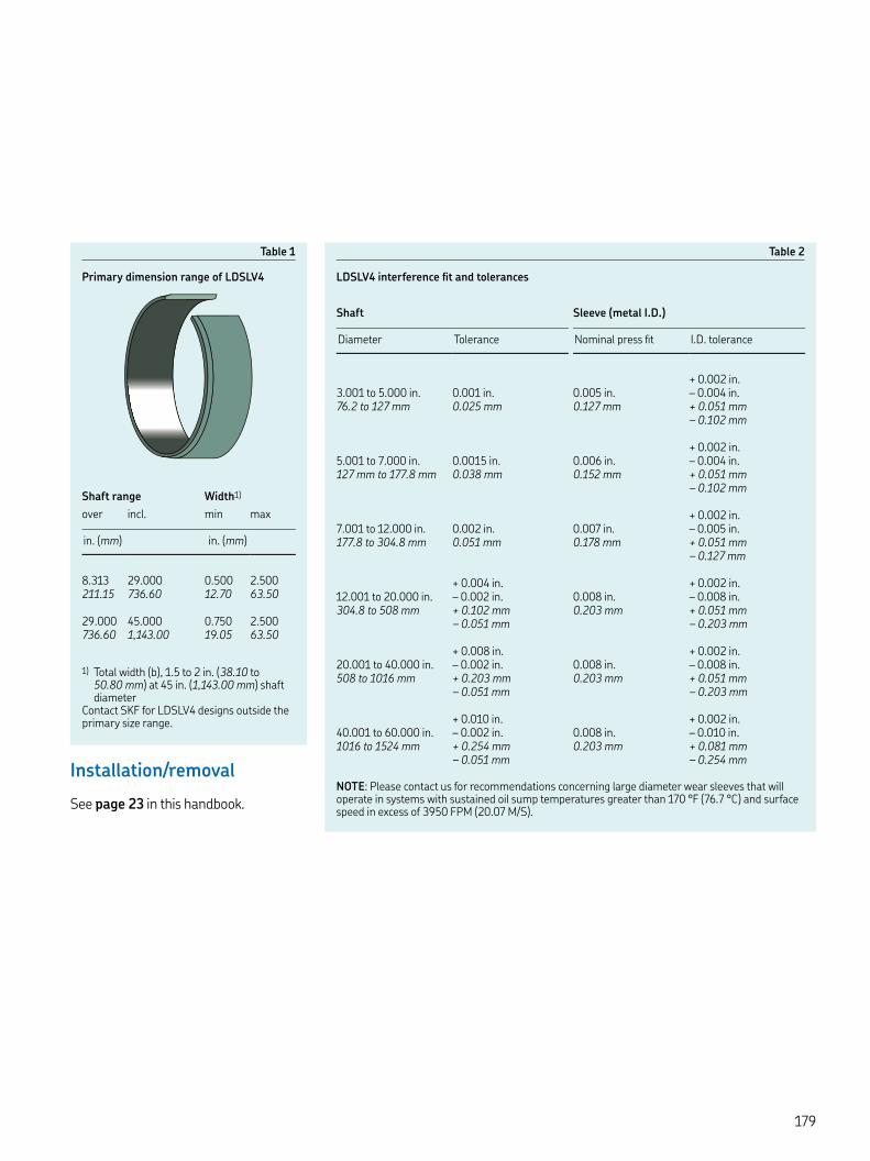
Table
Primary dimension range of LDSLV
Table
LDSLV interference fit and tolerances
) Total width (b), . to in. (. to . mm) at in. (,. mm) shaft diameter
Contact SKF for LDSLV designs outside the primary size range.
Shaft range Width)
over incl. min max
in. (mm) in. (mm)
. . . .. . . .
. . . .. ,. . .
Shaft Sleeve (metal I.D.)
Diameter Tolerance Nominal press fit I.D. tolerance
+ . in.. to . in. . in. . in. – . in.. to mm . mm . mm + . mm
– . mm
+ . in.. to . in. . in. . in. – . in. mm to . mm . mm . mm + . mm
– . mm
+ . in.. to . in. . in. . in. – . in.. to . mm . mm . mm + . mm
– . mm
+ . in. + . in.. to . in. – . in. . in. – . in.. to mm + . mm . mm + . mm
– . mm – . mm
+ . in. + . in.. to . in. – . in. . in. – . in. to mm + . mm . mm + . mm
– . mm – . mm
+ . in. + . in.. to . in. – . in. . in. – . in. to mm + . mm . mm + . mm
– . mm – . mmInstallation/removal
See page in this handbook.NOTE: Please contact us for recommendations concerning large diameter wear sleeves that will operate in systems with sustained oil sump temperatures greater than °F (. °C) and surface speed in excess of FPM (. M/S).

LDSLV Size listing
Inch Metric (mm)
SKF Part NumberShaft min. Shaft max.
Reference Installed OD Width Shaft min. Shaft max.
Reference Installed OD Width
d d D b d d D b
. . . . . . . . . . . . . . . . . . . . . . . . . . . . . . . . . . . . . . . . . . . . . . . . . . . . . . . . . . . . . . . . . . . . . . . . . . . . . . . . . . . . . . . . . . . . . . . . . . . . . . . . . . . . . . . . . . . . . . . . . . . . . . . . . . . . . . . . . . . . . . . . . . . . . . . . . . . . . . . . . . . . . . . . . . . . . . . . . . . . . . . . . . . . . . . . . . . . . . . . . . . . . . . . . . . . . . . . . . . . . . . . . . . . . . . . . . . . . . . . . . . . . . . . . . . . . . . . . . . . . . . . . . . . . . . . . . . . . . . . . . . . . . . . . . . . . . . . . . . . . . . . . . . . . . . . . . . . . . . . . . . . . . . . . . . . . . . . . . . . . . . . . . . . . . . . .
b
d1

Key features: ▲ WasteWatcher ■ Bore-Tite ◤ SS Case ◎ SS Spring ◆ Pressure seal up to 50 psi ◇ Cover plate required
LDSLV Size listing
Inch Metric (mm)
SKF Part NumberShaft min. Shaft max.
Reference Installed OD Width Shaft min. Shaft max.
Reference Installed OD Width
d d D b d d D b
. . . . . . . . . . . . . . . . . . . . . . . . . . . . . . . . . . . . . . . . . . . . . . . . . . . . . . . . . . . . . . . . . . . . . . . . . . . . . . . . . . . . . . . . . . . . . . . . . . . . . . . . . . . . . . . . . . . . . . . . . . . . . . . . . . . . . . . . . . . . . . . . . . . . . . . . . . . . . . . . . . . . . . . . . . . . . . . . . . . . . . . . . . . . . . . . . . . . . . . . . . . . . . . . . . . . . . . . . . . . . . . . . . . . . . . . . . . . . . . . . . . . . . . . . . . . . . . . . . . . . . . . . . . . . . . . . . . . . . . . . . . . . . . . . . . . . . . . . . . . . . . . . . . . . . . . . . . . . . . . . . . . . . . . . . . . . . . . . . . . . . . . . . . . . . . . . . . . . . .
b
d1
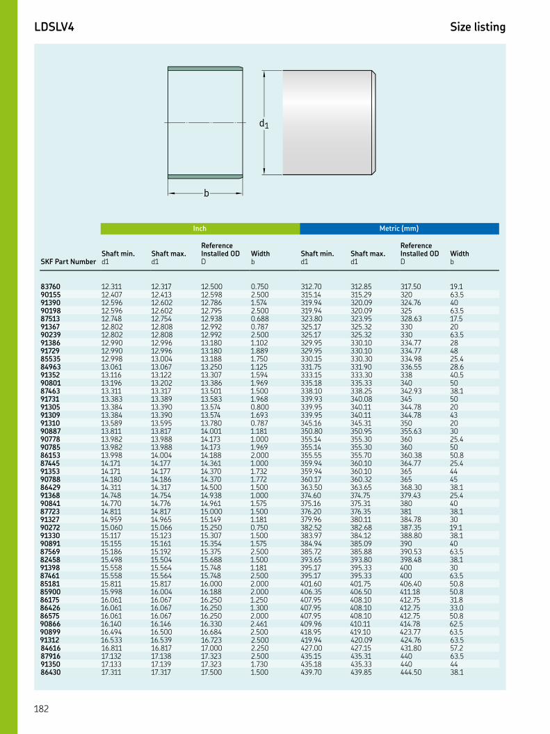
LDSLV Size listing
Inch Metric (mm)
SKF Part NumberShaft min. Shaft max.
Reference Installed OD Width Shaft min. Shaft max.
Reference Installed OD Width
d d D b d d D b
. . . . . . . . . . . . . . . . . . . . . . . . . . . . . . . . . . . . . . . . . . . . . . . . . . . . . . . . . . . . . . . . . . . . . . . . . . . . . . . . . . . . . . . . . . . . . . . . . . . . . . . . . . . . . . . . . . . . . . . . . . . . . . . . . . . . . . . . . . . . . . . . . . . . . . . . . . . . . . . . . . . . . . . . . . . . . . . . . . . . . . . . . . . . . . . . . . . . . . . . . . . . . . . . . . . . . . . . . . . . . . . . . . . . . . . . . . . . . . . . . . . . . . . . . . . . . . . . . . . . . . . . . . . . . . . . . . . . . . . . . . . . . . . . . . . . . . . . . . . . . . . . . . . . . . . . . . . . . . . . . . . . . . . . . . . . . . . . . . . . . . . . . . . . . . . . . . .
b
d1

Key features: ▲ WasteWatcher ■ Bore-Tite ◤ SS Case ◎ SS Spring ◆ Pressure seal up to 50 psi ◇ Cover plate required
LDSLV Size listing
Inch Metric (mm)
SKF Part NumberShaft min. Shaft max.
Reference Installed OD Width Shaft min. Shaft max.
Reference Installed OD Width
d d D b d d D b
. . . . . . . . . . . . . . . . . . . . . . . . . . . . . . . . . . . . . . . . . . . . . . . . . . . . . . . . . . . . . . . . . . . . . . . . . . . . . . . . . . . . . . . . . . . . . . . . . . . . . . . . . . . . . . . . . . . . . . . . . . . . . . . . . . . . . . . . . . . . . . . . . . . . . . . . . . . . . . . . . . . . . . . . . . . . . . . . . . . . . . . . . . . . . . . . . . . . . . . . . . . . . . . . . . . . . . . . . . . . . . . . . . . . . . . . . . . . . . . . . . . . . . . . . . . . . . . . . . . . . . . . . . . . . . . . . . . . . . . . . . . . . . . . . . . . . . . . . . . . . . . . . . . . . . . . . . . . . . . . . . . . . . . . . . . . . . . . . . . . . . . . . . . . . . . . . . . . . . . . . . . . . .
b
d1

Don’t s
ee t
he
size
you n
eed?
SK
F F
lex
seals
are
ava
ilable
fast
in c
ust
om
ized
siz
es a
nd m
ate
rials
wit
h N
O toolin
g c
harg
es.
LDSLV Size listing
Inch Metric (mm)
SKF Part NumberShaft min. Shaft max.
Reference Installed OD Width Shaft min. Shaft max.
Reference Installed OD Width
d d D b d d D b
. . . . . . . . . . . . . . . . . . . . . . . . . . . . . . . . . . . . . . . . . . . . . . . . . . . . . . . . . . . . . . . . . . . . . . . . . . . . . . . . . . . . . . . . . . . . . . . . . . . . . . . . . . . . . . . . . . . . . . . . . . . . . . . . . . . . . . . . . . . . . . . . . . . . . . . . . . . . . . . . . . . . . . . . . . . . . . . . . . . . . . . . . . . . . . . . . . . . . . . . . . . . . . . . . . . . . . . . . . . . . . . . . . . . . . . . . . . . . . . . . . . . . . . . . . . . . . . . . . . . . . . . . . . . . . . . . . . . . . . . . . . . . . . . . . . .
b
d1


Metal face seals
HDDF metal face seals from SKF
(† fig. ) are designed for severe
operating conditions at relatively
low circumferential speeds. They
offer reliable protection against
solid and liquid contaminants as
well as leak-proof lubricant
retention.
Typical applications
Originally developed for off-road and tracked vehicles, HDDF metal face seals († fig. ) have proven equally suitable in applications that need protection against sand, soil, mud, water and more. These include:
• Mixers and conveyors
• Sand treatment equipment
• Mining equipment
• Construction equipment
• Agricultural machinery
• Washing equipment
• Grinding mills /pulverizing equipment
Design features
HDDF seals consist of two identical metal sealing rings and two similar Belleville washers (cup springs) made of nitrile or fluoro rubber compounds, specifically developed for these seals († fig. ). The sealing rings are made of wear- and cor-rosion-resistant cast alloy and have finely finished sliding and sealing surfaces.
The Belleville washers of nitrile or fluoro rubber provide the necessary uniform face loading and effective sealing at the bore and outside diameters. Adequate tolerances between the seal assembly and the bore are critical for proper seal-ing performance.
Lubricant requirements
A lubricant should be applied on the dynamic sealing surfaces of a metal face seal to prevent scoring and cover at least % of the sealing surface to properly lubricate and cool the sealing rings. The lubricant can be either a detergent like SAE W-, or a mineral-based oil ranging from WT to WT, depend-ing on the ambient temperature. Some oils contain additives that make them incompatible with elastomers, which can cause degradation of the Belleville wash-ers, especially when exposed to elevated temperatures.
Although mineral oils are always the rec-ommended lubricant, a grease lubricant can also be used in some slowly rotating or oscillating applications, where the seal face surface speed does not exceed ft/min (. m/s). At higher speeds, an oil lubricant is required, not only to pro-vide lubrication to the sealing faces, but also to cool the sealing rings.
Figure
HDDF seal
Figure
HDDF application
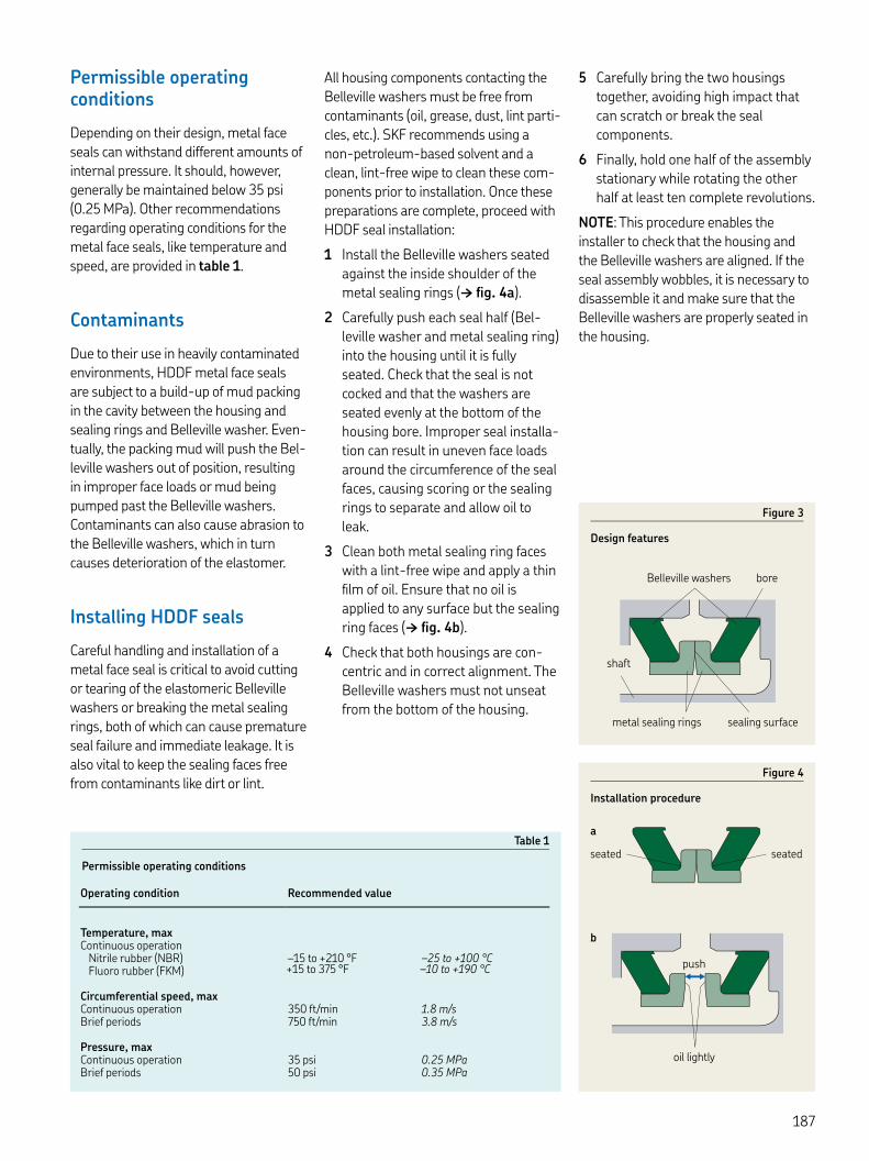
Permissible operating conditions
Depending on their design, metal face seals can withstand different amounts of internal pressure. It should, however, generally be maintained below psi (. MPa). Other recommendations regarding operating conditions for the metal face seals, like temperature and speed, are provided in table .
Contaminants
Due to their use in heavily contaminated environments, HDDF metal face seals are subject to a build-up of mud packing in the cavity between the housing and sealing rings and Belleville washer. Even-tually, the packing mud will push the Bel-leville washers out of position, resulting in improper face loads or mud being pumped past the Belleville washers. Contaminants can also cause abrasion to the Belleville washers, which in turn causes deterioration of the elastomer.
Installing HDDF seals
Careful handling and installation of a metal face seal is critical to avoid cutting or tearing of the elastomeric Belleville washers or breaking the metal sealing rings, both of which can cause premature seal failure and immediate leakage. It is also vital to keep the sealing faces free from contaminants like dirt or lint.
All housing components contacting the Belleville washers must be free from contaminants (oil, grease, dust, lint parti-cles, etc.). SKF recommends using a non-petroleum-based solvent and a clean, lint-free wipe to clean these com-ponents prior to installation. Once these preparations are complete, proceed with HDDF seal installation:
Install the Belleville washers seated against the inside shoulder of the metal sealing rings († fig. a).
Carefully push each seal half (Bel-leville washer and metal sealing ring) into the housing until it is fully seated. Check that the seal is not cocked and that the washers are seated evenly at the bottom of the housing bore. Improper seal installa-tion can result in uneven face loads around the circumference of the seal faces, causing scoring or the sealing rings to separate and allow oil to leak.
Clean both metal sealing ring faces with a lint-free wipe and apply a thin film of oil. Ensure that no oil is applied to any surface but the sealing ring faces († fig. b).
Check that both housings are con-centric and in correct alignment. The Belleville washers must not unseat from the bottom of the housing.
Carefully bring the two housings together, avoiding high impact that can scratch or break the seal components.
Finally, hold one half of the assembly stationary while rotating the other half at least ten complete revolutions.
NOTE: This procedure enables the installer to check that the housing and the Belleville washers are aligned. If the seal assembly wobbles, it is necessary to disassemble it and make sure that the Belleville washers are properly seated in the housing.
Figure
Installation procedure
seated
a
b
push
oil lightly
seated
Figure
Design features
Belleville washers bore
shaft
sealing surfacemetal sealing rings
Table
Permissible operating conditions
Operating condition Recommended value
Temperature, maxContinuous operation
Nitrile rubber (NBR) – to + °F – to + °CFluoro rubber (FKM) + to °F – to + °C
Circumferential speed, maxContinuous operation ft/min . m/sBrief periods ft/min . m/s
Pressure, maxContinuous operation psi . MPaBrief periods psi . MPa

Metal face seals Size listing
B
B1B2
b
r
d1d3 D1D
3–5 m m
(100–200 µin.)
Inch
SKF part number Lip mat’l Inch dimensions
Shaft diameter
Bore diameter Operating width Seal inside diameter
Bore depth
Recom-mendedshoulder diameter
Under-cut
Sealing ringwidth
Radius
Dmax
D B dmin
B Dmax
min)
Bmin
b max
r max
in.
R . . ±. . ±. . . . - - . . R . . ±. . ±. . . . - - . . R . . ±. . ±. . . . - - . . R . . ±. . ±. . . . - - . . R . . ±. . ±. . . . - - . . R . . ±. . ±. . . . - - . . R . . ±. . ±. . . . - - . . R . . ±. . ±. . . . - - . . R . . ±. . ±. . . . - - . . R . . ±. . ±. . . . - - . . R . . ±. . ±. . . . - - . . R . . ±. . ±. . . . - - . . R . . ±. . ±. . . . - - . . R . . ±. . ±. . . . - - . . R . . ±. . ±. . . . . . . . R . . ±. . ±. . . . . . . . R . . ±. . ±. . . . . . . . R . . ±. . ±. . . . - - . . R . . ±. . ±. . . . - - . . R . . ±. . ±. . . . - - . . R . . ±. . ±. . . . . . . . R . . ±. . ±. . . . - - . . R . . ±. . ±. . . . . . . . R . . ±. . ±. . . . - - . . R . . ±. . ±. . . . - - . . R . . ±. . ±. . . . . . . . R . . ±. . ±. . . . - - . . R . . ±. . ±. . . . . . . . R . . ±. . ±. . . . - - . . R . . ±. . ±. . . . - - . . V . . ±. . ±. . . . - - . . R . . ±. . ±. . . . . . . . R . . ±. . ±. . . . . . . . R . . ±. . ±. . . . - - . . V . . ±. . ±. . . . - - . . V . . ±. . ±. . . . - - . .
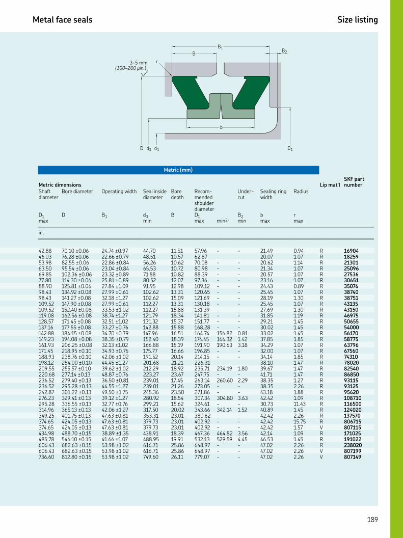
Key features: ▲ WasteWatcher ■ Bore-Tite ◤ SS Case ◎ SS Spring ◆ Pressure seal up to 50 psi ◇ Cover plate required
Metal face seals Size listing
B
B1B2
b
r
d1d3 D1D
3–5 m m
(100–200 µin.)
Metric (mm)
Metric dimensions Lip mat’lSKF part number
Shaft diameter
Bore diameter Operating width Seal inside diameter
Bore depth
Recom-mendedshoulder diameter
Under-cut
Sealing ringwidth
Radius
Dmax
D B dmin
B Dmax
min)
Bmin
b max
r max
in.
. . ±. . ±. . . . - - . . R . . ±. . ±. . . . - - . . R . . ±. . ±. . . . - - . . R . . ±. . ±. . . . - - . . R . . ±. . ±. . . . - - . . R . . ±. . ±. . . . - - . . R . . ±. . ±. . . . - - . . R . . ±. . ±. . . . - - . . R . . ±. . ±. . . . - - . . R . . ±. . ±. . . . - - . . R . . ±. . ±. . . . - - . . R . . ±. . ±. . . . - - . . R . . ±. . ±. . . . - - . . R . . ±. . ±. . . . - - . . R . . ±. . ±. . . . . . . . R . . ±. . ±. . . . . . . . R . . ±. . ±. . . . . . . . R . . ±. . ±. . . . - - . . R . . ±. . ±. . . . - - . . R . . ±. . ±. . . . - - . . R . . ±. . ±. . . . . . . . R . . ±. . ±. . . . - - . . R . . ±. . ±. . . . . . . . R . . ±. . ±. . . . - - . . R . . ±. . ±. . . . - - . . R . . ±. . ±. . . . . . . . R . . ±. . ±. . . . - - . . R . . ±. . ±. . . . . . . . R . . ±. . ±. . . . - - . . R . . ±. . ±. . . . - - . . R . . ±. . ±. . . . - - . . V . . ±. . ±. . . . . . . . R . . ±. . ±. . . . . . . . R . . ±. . ±. . . . - - . . R . . ±. . ±. . . . - - . . V . . ±. . ±. . . . - - . . V

Axial clamp seals
SKF axial clamp seals are
designed for large and very large
shaft diameters. They are suita-
ble for use as primary seals, or as
secondary seals in applications
where the primary seals are sub-
jected to excessive solid or fluid
contaminants. Axial clamp seals
do not rotate but seal axially
against a rotating counterface.
SKF axial clamp seals are made of pro-filed strips of non-reinforced nitrile rub-ber and are held firmly in position by stainless steel band clamps. They are available for shaft diameters ranging from . to in. ( to , mm).
The standard range of SKF axial clamp seals is intended for inch-size shaft diameters. Because axial clamp seals are typically installed with an approximate . in. ( mm) gap between the ends, they may also be used for metric shaft diameters.
Figure
Axial clamp seal designs
Table
Application tolerances
Dimension Tolerance Axial clamp seals
CT
Seal seat diameter, d in. ± . . – .mm ±. . – ,
Seal fitted width, B in. ± . . – .mm ±. . – .
Seal seat width, b in. ± . . – .mm ±. . –
Lip height, c in. ± . .mm ±. .
Gap width, B in. .mm .
d
b
c
B
B
CT

Basic design features
CT seals († fig. ) have the basic design and are held in position by a band clamp.
The maximum permissible axial dis-placement relative to the bore is . in. (+. mm).
Sealing arrangement design
To obtain reliable sealing performance, the seal seat diameter (d), seal seat width (b) and the seal fitted width (B) should meet the requirements listed in table . To simplify alignment, the seal should abut a shoulder.
Finely turned bores are adequate for axial clamp seals. The appropriate sur-face roughness values are μin (Ra . μm) and μin (Rt μm).
Typically, after installation, CT axial clamp seals have an approximate in. ( mm) gap between the ends. This should be arranged at the o’clock position († fig. ) to facilitate installation and drainage of contaminants.
Butt-joint seals are also available for cer-tain applications.
Installation instructions
Axial clamp seals are supplied as rolled-up coils. During installation they are placed in position on their seat in the housing and bolted lightly together. They are then pushed forward toward the counterface and the gap (or joint) between the two ends is arranged at the o’clock position († fig. ). The clamps are finally tightened.
The torque applied to the clamp screws should not exceed Nm.
Figure
Sealing arrangement and installation
A
AA–A
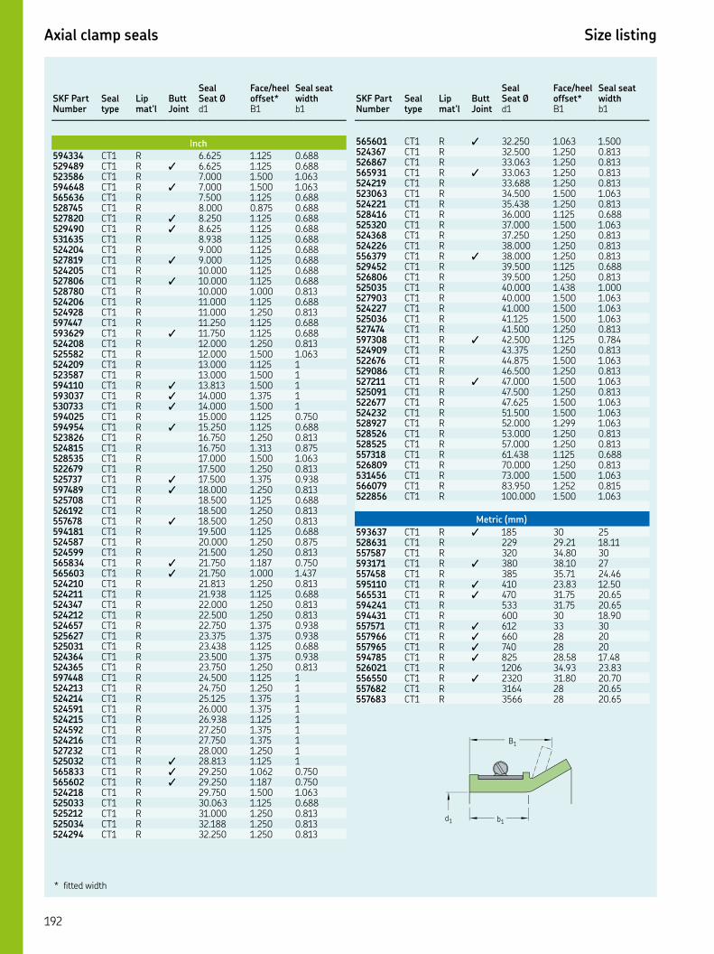
Axial clamp seals Size listing
SKF Part Number
Seal type
Lip mat’l
Butt Joint
Seal Seat Ø
Face/heel offset*
Seal seat width
d B b
Inch
CT R . . . CT R ✓ . . . CT R . . . CT R ✓ . . . CT R . . . CT R . . . CT R ✓ . . . CT R ✓ . . . CT R . . . CT R . . . CT R ✓ . . . CT R . . . CT R ✓ . . . CT R . . . CT R . . . CT R . . . CT R . . . CT R ✓ . . . CT R . . . CT R . . . CT R . . CT R . . CT R ✓ . . CT R ✓ . . CT R ✓ . . CT R . . . CT R ✓ . . . CT R . . . CT R . . . CT R . . . CT R . . . CT R ✓ . . . CT R ✓ . . . CT R . . . CT R . . . CT R ✓ . . . CT R . . . CT R . . . CT R . . . CT R ✓ . . . CT R ✓ . . . CT R . . . CT R . . . CT R . . . CT R . . . CT R . . . CT R . . . CT R . . . CT R . . . CT R . . . CT R . . CT R . . CT R . . CT R . . CT R . . CT R . . CT R . . CT R . . CT R ✓ . . CT R ✓ . . . CT R ✓ . . . CT R . . . CT R . . . CT R . . . CT R . . . CT R . . .
SKF Part Number
Seal type
Lip mat’l
Butt Joint
Seal Seat Ø
Face/heel offset*
Seal seat width
d B b
CT R ✓ . . . CT R . . . CT R . . . CT R ✓ . . . CT R . . . CT R . . . CT R . . . CT R . . . CT R . . . CT R . . . CT R . . . CT R ✓ . . . CT R . . . CT R . . . CT R . . . CT R . . . CT R . . . CT R . . . CT R . . . CT R ✓ . . . CT R . . . CT R . . . CT R . . . CT R ✓ . . . CT R . . . CT R . . . CT R . . . CT R . . . CT R . . . CT R . . . CT R . . . CT R . . . CT R . . . CT R . . . CT R . . .
Metric (mm)
CT R ✓ CT R . . CT R . CT R ✓ . CT R . . CT R ✓ . . CT R ✓ . . CT R . . CT R . CT R ✓ CT R ✓ CT R ✓ CT R ✓ . . CT R . . CT R ✓ . . CT R . CT R .
* fitted width
B1
b1
d1

Pressure seals
CRW and CRWA seals
CRW and CRWA seals are designed to withstand moderate pressure differen-tials. They have an SKF Wave lip to reduce heat generation and a metal out-side diameter for easy installation and a firm and accurate fit in the housing bore; most designs feature SKF Bore Tite Coat-ing on the outside diameter. CRW and CRWA seals will both operate under a maximum pressure of psi.
• CRW: Seal with one steel case, SKF Wave lip and a carbon steel garter spring.
• CRWA: Seal with one steel case, SKF Wave lip, a carbon steel garter spring and an auxiliary contacting lip for additional contaminant exclusion ability. A shoulder or retaining ring should be used at the low-pressure side of the seal to prevent it from being pressed out of the housing bore.
CRW and CRWA seals are available in inch sizes with sealing lips made of either nitrile rubber or the SKF FKM compound SKF Duralife. Other materials are also available on request.
HMSAP and HMSAP seals
CR Seals also offers a limited number of alternative sizes in HMSAP and HMSAP configurations. These are standard oil seals with a straight lip capa-ble of handling up to psi pressure. A shoulder or retaining ring is required to hold the seals in place.
CRW
HMSAP
CRWA
HMSAP
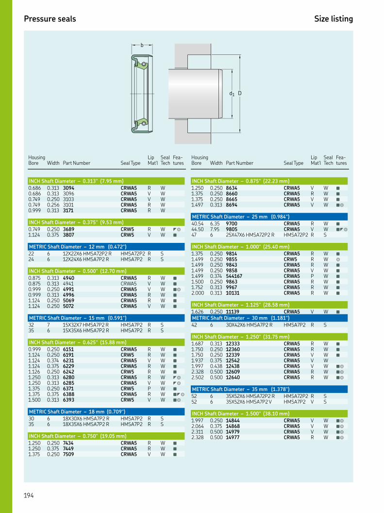
Pressure seals Size listing
b
d1 D
Housing Bore
Width
Part Number
Seal Type
Lip Mat'l
Seal Tech
Fea-tures
INCH Shaft Diameter – 0.313" (7.95 mm)
. . CRWA R W. . CRWA V W. . CRWA V W. . CRWA R W. . CRWA R W
INCH Shaft Diameter – 0.375" (9.53 mm)
. . CRW R W ◤◎
. . CRW V W ■
METRIC Shaft Diameter – 12 mm (0.472")
XX HMSAP R HMSAP R S XX HMSAP R HMSAP R S
INCH Shaft Diameter – 0.500" (12.70 mm)
. . CRWA R W ■
. . CRWA V W ■
. . CRWA V W ■◎
. . CRWA R W ■
. . CRWA R W ■
. . CRWA V W ■
METRIC Shaft Diameter – 15 mm (0.591")
XX HMSAP R HMSAP R S XX HMSAP R HMSAP R S
INCH Shaft Diameter – 0.625" (15.88 mm)
. . CRWA R W ■
. . CRW R W ■
. . CRWA V W ■
. . CRWA R W ■
. . CRW R W ■
. . CRWA R W ◤◎
. . CRWA V W ◤◎
. . CRW P W ■
. . CRWA R W ■◤◎
. . CRW V W ■◎
METRIC Shaft Diameter – 18 mm (0.709")
XX HMSAP R HMSAP R S XX HMSAP R HMSAP R S
INCH Shaft Diameter – 0.750" (19.05 mm)
. . CRWA R W ■
. . CRWA R W ■
. . CRWA V W ■
Housing Bore
Width
Part Number
Seal Type
Lip Mat'l
Seal Tech
Fea-tures
INCH Shaft Diameter – 0.875" (22.23 mm)
. . CRWA V W ■
. . CRWA R W ■
. . CRWA V W ■
. . CRWA V W ■◎
METRIC Shaft Diameter – 25 mm (0.984")
. . CRWA R W ■
. . CRWA V W ■◤◎
XX HMSAP R HMSAP R S
INCH Shaft Diameter – 1.000" (25.40 mm)
. . CRWA R W ■
. . CRW R W ◎
. . CRWA R W ■
. . CRWA V W ■
. . CRWA P W ■
. . CRWA R W ■
. . CRWA R W ■
. . CRWA R W ■
INCH Shaft Diameter – 1.125" (28.58 mm)
. . CRWA V W ■
METRIC Shaft Diameter – 30 mm (1.181")
XX HMSAP R HMSAP R S
INCH Shaft Diameter – 1.250" (31.75 mm)
. . CRWA R W ■
. . CRWA R W ■
. . CRWA V W ■
. . CRWA V W. . CRWA V W ■◎
. . CRWA R W ■◎
. . CRWA R W ■◎
METRIC Shaft Diameter – 35 mm (1.378")
XX HMSAP R HMSAP R S XX HMSAP V HMSAP V S
INCH Shaft Diameter – 1.500" (38.10 mm)
. . CRWA V W ■◎
. . CRWA V W ■◎
. . CRWA V W ■◎
. . CRWA R W ■◎
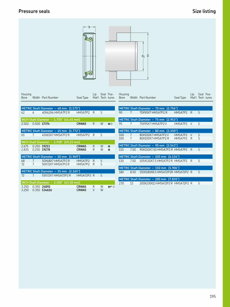
Key features: ▲ WasteWatcher ■ Bore-Tite ◤ SS Case ◎ SS Spring ◆ Pressure seal up to 50 psi ◇ Cover plate required
Pressure seals Size listing
b
d1 D
Housing Bore
Width
Part Number
Seal Type
Lip Mat'l
Seal Tech
Fea-tures
METRIC Shaft Diameter – 40 mm (1.575")
XX HMSAP R HMSAP R S
INCH Shaft Diameter – 1.750" (44.45 mm)
. . CRWA R W ■◎
METRIC Shaft Diameter – 45 mm (1.772")
XX HMSAP R HMSAP R S
INCH Shaft Diameter – 1.938" (49.23 mm)
. . CRWA R W ■
. . CRWA R W ■
METRIC Shaft Diameter – 50 mm (1.969")
XX HMSAP R HMSAP R S XX HMSAP R HMSAP R S
METRIC Shaft Diameter – 55 mm (2.165")
XX HMSAP R HMSAP R S
INCH Shaft Diameter – 2.500" (63.50 mm)
. . CRWA R W ■◤◎
. . CRWA V W
Housing Bore
Width
Part Number
Seal Type
Lip Mat'l
Seal Tech
Fea-tures
METRIC Shaft Diameter – 70 mm (2.756")
XX HMSAP R HMSAP R S
METRIC Shaft Diameter – 75 mm (2.953")
XX HMSAP V HMSAP V S
METRIC Shaft Diameter – 80 mm (3.150")
XX HMSAP V HMSAP V S XX HMSAP R HMSAP R S
METRIC Shaft Diameter – 90 mm (3.543")
. XX. HMSAP R HMSAP R S
METRIC Shaft Diameter – 105 mm (4.134")
. XX. HMSAP R HMSAP R S
METRIC Shaft Diameter – 150 mm (5.906")
. XX. HMSAPR HMSAP R S
METRIC Shaft Diameter – 200 mm (7.835")
XX HMSAP R HMSAP R S
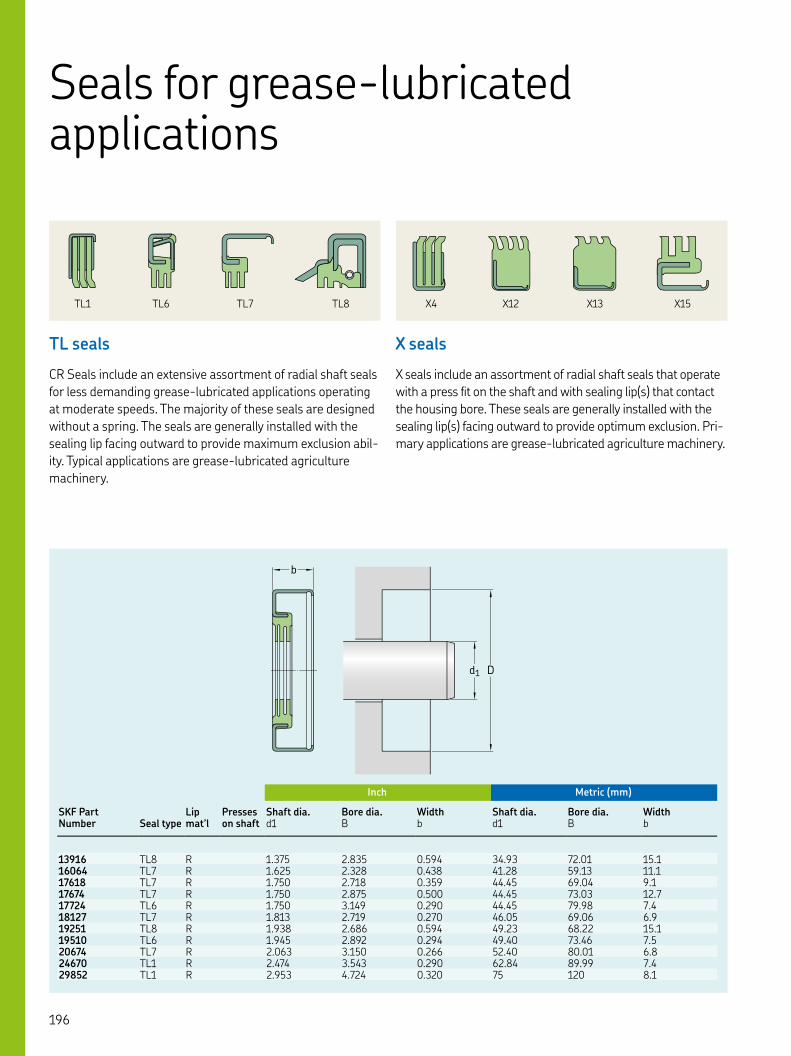
Inch Metric (mm)
SKF Part Number Seal type
Lip mat’l
Presses on shaft
Shaft dia. Bore dia. Width Shaft dia. Bore dia. Widthd B b d B b
TL R . . . . . . TL R . . . . . . TL R . . . . . . TL R . . . . . . TL R . . . . . . TL R . . . . . . TL R . . . . . . TL R . . . . . . TL R . . . . . . TL R . . . . . . TL R . . . .
b
d1 D
Seals for grease-lubricated applications
TL seals
CR Seals include an extensive assortment of radial shaft seals for less demanding grease-lubricated applications operating at moderate speeds. The majority of these seals are designed without a spring. The seals are generally installed with the sealing lip facing outward to provide maximum exclusion abil-ity. Typical applications are grease-lubricated agriculture machinery.
X seals
X seals include an assortment of radial shaft seals that operate with a press fit on the shaft and with sealing lip(s) that contact the housing bore. These seals are generally installed with the sealing lip(s) facing outward to provide optimum exclusion. Pri-mary applications are grease-lubricated agriculture machinery.
TL XTL XTL XTL X
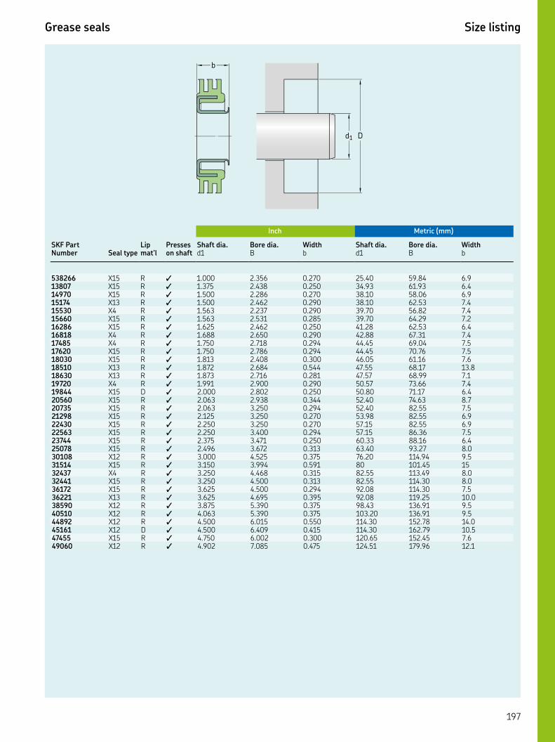
Key features: ▲ WasteWatcher ■ Bore-Tite ◤ SS Case ◎ SS Spring ◆ Pressure seal up to 50 psi ◇ Cover plate required
Grease seals Size listing
Inch Metric (mm)
SKF Part Number Seal type
Lip mat’l
Presses on shaft
Shaft dia. Bore dia. Width Shaft dia. Bore dia. Widthd B b d B b
X R ✓ . . . . . . X R ✓ . . . . . . X R ✓ . . . . . . X R ✓ . . . . . . X R ✓ . . . . . . X R ✓ . . . . . . X R ✓ . . . . . . X R ✓ . . . . . . X R ✓ . . . . . . X R ✓ . . . . . . X R ✓ . . . . . . X R ✓ . . . . . . X R ✓ . . . . . . X R ✓ . . . . . . X D ✓ . . . . . . X R ✓ . . . . . . X R ✓ . . . . . . X R ✓ . . . . . . X R ✓ . . . . . . X R ✓ . . . . . . X R ✓ . . . . . . X R ✓ . . . . . . X R ✓ . . . . . . X R ✓ . . . . X R ✓ . . . . . . X R ✓ . . . . . . X R ✓ . . . . . . X R ✓ . . . . . . X R ✓ . . . . . . X R ✓ . . . . . . X R ✓ . . . . . . X D ✓ . . . . . . X R ✓ . . . . . . X R ✓ . . . . . .
b
d1 D
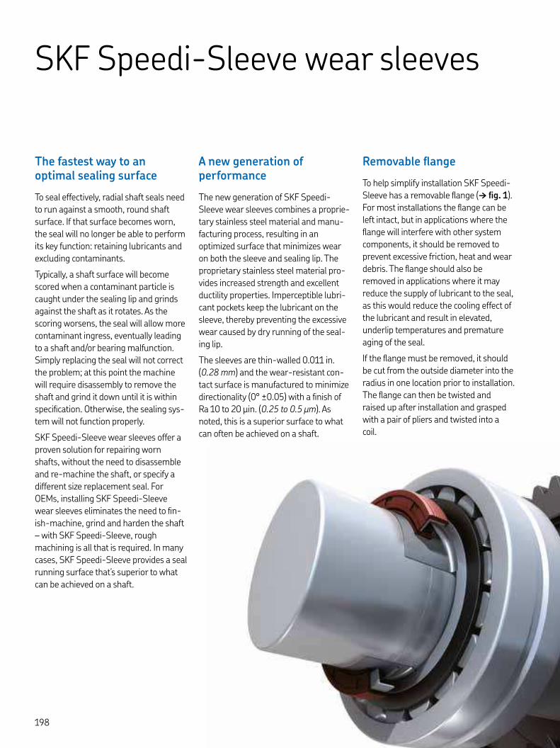
SKF Speedi-Sleeve wear sleeves
The fastest way to an optimal sealing surface
To seal effectively, radial shaft seals need to run against a smooth, round shaft surface. If that surface becomes worn, the seal will no longer be able to perform its key function: retaining lubricants and excluding contaminants.
Typically, a shaft surface will become scored when a contaminant particle is caught under the sealing lip and grinds against the shaft as it rotates. As the scoring worsens, the seal will allow more contaminant ingress, eventually leading to a shaft and/or bearing malfunction. Simply replacing the seal will not correct the problem; at this point the machine will require disassembly to remove the shaft and grind it down until it is within specification. Otherwise, the sealing sys-tem will not function properly.
SKF Speedi-Sleeve wear sleeves offer a proven solution for repairing worn shafts, without the need to disassemble and re-machine the shaft, or specify a different size replacement seal. For OEMs, installing SKF Speedi-Sleeve wear sleeves eliminates the need to fin-ish-machine, grind and harden the shaft – with SKF Speedi-Sleeve, rough machining is all that is required. In many cases, SKF Speedi-Sleeve provides a seal running surface that’s superior to what can be achieved on a shaft.
A new generation of performance
The new generation of SKF Speedi-Sleeve wear sleeves combines a proprie-tary stainless steel material and manu-facturing process, resulting in an optimized surface that minimizes wear on both the sleeve and sealing lip. The proprietary stainless steel material pro-vides increased strength and excellent ductility properties. Imperceptible lubri-cant pockets keep the lubricant on the sleeve, thereby preventing the excessive wear caused by dry running of the seal-ing lip.
The sleeves are thin-walled . in. (. mm) and the wear-resistant con-tact surface is manufactured to minimize directionality (° ±.) with a finish of Ra to μin. (. to . μm). As noted, this is a superior surface to what can often be achieved on a shaft.
Removable flange
To help simplify installation SKF Speedi-Sleeve has a removable flange († fig. ). For most installations the flange can be left intact, but in applications where the flange will interfere with other system components, it should be removed to prevent excessive friction, heat and wear debris. The flange should also be removed in applications where it may reduce the supply of lubricant to the seal, as this would reduce the cooling effect of the lubricant and result in elevated, underlip temperatures and premature aging of the seal.
If the flange must be removed, it should be cut from the outside diameter into the radius in one location prior to installation. The flange can then be twisted and raised up after installation and grasped with a pair of pliers and twisted into a coil.

SKF Speedi-Sleeve Gold
For highly abrasive applications, the new generation of SKF Speedi-Sleeve is also available in the Gold version. A thin, metallic coating applied to the base stainless steel imparts a gold color and significantly increases durability. SKF Speedi-Sleeve Gold is particularly effec-tive in environments where there are abrasive contaminants, especially when combined with a seal manufactured from the SKF FKM material SKF Duralife. This sealing system solution lasted , hours in a contamination test.
The installation procedure is common to both SKF Speedi-Sleeve designs and the original seal size can still be used. All sleeves listed in the following product tables can be manufactured as SKF Speedi-Sleeve Gold.
Available size range
The standard size range covers sleeves for shaft diameters from . to in. (. to . mm). Depending on production quantities, non-standard sizes can be manufactured (for additional information, contact SKF). Each sleeve is designed to fit a specific shaft range, usu-ally above and below the nominal shaft diameter. This permits some flexibility to accommodate variations in the actual shaft diameter.
Selecting the sleeve size
To determine the appropriate sleeve size, the shaft must be carefully cleaned first. The diameter of an undamaged section of the shaft surface should then be measured on at least three different planes. The arithmetical mean of these measurements determines the size of the required SKF Speedi-Sleeve. If the value lies within the permissible range listed in the product table for the shaft diameter d, the selected SKF Speedi-Sleeve will provide an adequately tight fit on the shaft and will not require an adhesive.
Figure
SKF Speedi-Sleeve removable flange
The standard size range covers sleeves for shaft diameters from . to in. (. to . mm)
SKF Speedi-Sleeve new generation, Gold version
Removable flange

SKF Speedi-Sleeve Size listing
Inch
Nominal shaft size
SKF part number Style
Shaft dia. min Shaft dia. max‘ On-shaft’ width Total width Flange dia.
Max tear groove offset
d d b b D B
mm STD . . . . . .. in. STD . . . . . . mm STD . . . . . .. in. STD . . . . . . mm STD . . . . . .. in. STD . . . . . .. in. GOLD . . . . . . mm STD . . . . . . mm STD . . . . . .. in. STD . . . . . . mm STD . . . . . .. in. STD . . . . . .. in. GOLD . . . . . .. in. STD . . . . . .. in. STD . . . . . . mm STD . . . . . . mm STD . . . . . .. in. STD . . . . . .. in. STD . . . . . . mm STD . . . . . . mm STD . . . . . .. in. GOLD . . . . . .. in. STD . . . . . .. in. STD . . . . . .. in. STD . . . . . .. in. GOLD . . . . . . mm STD . . . . . .. in. STD . . . . . .. in. STD . . . . . . mm STD . . . . . . mm GOLD . . . . . .. in. STD . . . . . .. in. GOLD . . . . . . mm STD . . . . . .. in. or mm STD . . . . . .. in. or mm GOLD . . . . . .. in. STD . . . . . . mm STD . . . . . . mm GOLD . . . . . .. in. STD . . . . . .. in. GOLD . . . . . .. in. STD . . . . . .. in. STD . . . . . .. in. STD . . . . . . mm STD . . . . . .. in. STD . . . . . . mm STD . . . . . .. in. STD . . . . . .
b1B
b
D d1
rmax 0.125 in.
Green shading = inch blue shading = metric gray shading = both
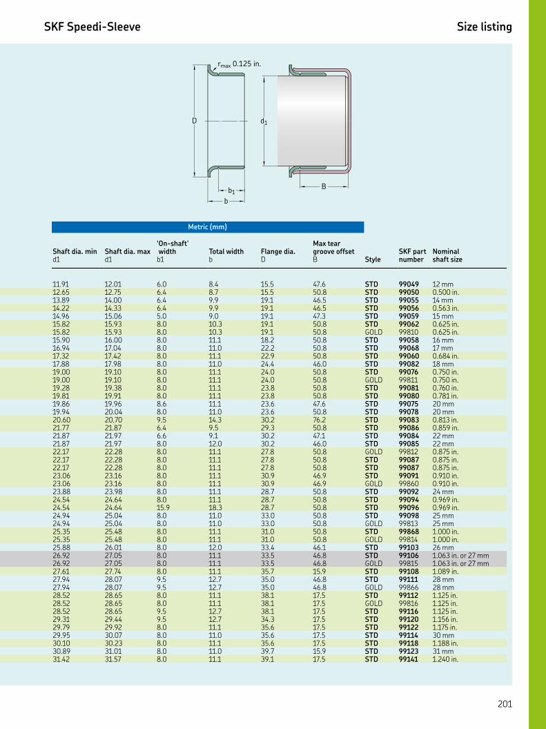
Key features: ▲ WasteWatcher ■ Bore-Tite ◤ SS Case ◎ SS Spring ◆ Pressure seal up to 50 psi ◇ Cover plate required
SKF Speedi-Sleeve Size listing
Metric (mm)
Shaft dia. min Shaft dia. max‘ On-shaft’ width Total width Flange dia.
Max tear groove offset
StyleSKF part number
Nominal shaft sized d b b D B
. . . . . . STD mm. . . . . . STD . in.. . . . . . STD mm. . . . . . STD . in.. . . . . . STD mm. . . . . . STD . in.. . . . . . GOLD . in.. . . . . . STD mm. . . . . . STD mm. . . . . . STD . in.. . . . . . STD mm. . . . . . STD . in.. . . . . . GOLD . in.. . . . . . STD . in.. . . . . . STD . in.. . . . . . STD mm. . . . . . STD mm. . . . . . STD . in.. . . . . . STD . in.. . . . . . STD mm. . . . . . STD mm. . . . . . GOLD . in.. . . . . . STD . in.. . . . . . STD . in.. . . . . . STD . in.. . . . . . GOLD . in.. . . . . . STD mm. . . . . . STD . in.. . . . . . STD . in.. . . . . . STD mm. . . . . . GOLD mm. . . . . . STD . in.. . . . . . GOLD . in.. . . . . . STD mm. . . . . . STD . in. or mm. . . . . . GOLD . in. or mm. . . . . . STD . in.. . . . . . STD mm. . . . . . GOLD mm. . . . . . STD . in.. . . . . . GOLD . in.. . . . . . STD . in.. . . . . . STD . in.. . . . . . STD . in.. . . . . . STD mm. . . . . . STD . in.. . . . . . STD mm. . . . . . STD . in.
b1B
b
D d1
rmax 0.125 in.

SKF Speedi-Sleeve Size listing
Inch
Nominal shaft size
SKF part number Style
Shaft dia. min Shaft dia. max‘ On-shaft’ width Total width Flange dia.
Max tear groove offset
d d b b D B
. in. STD . . . . . .. in. GOLD . . . . . . mm STD . . . . . . mm GOLD . . . . . . mm STD . . . . . .. in. STD . . . . . .. in. STD . . . . . . mm STD . . . . . .. in. STD . . . . . .. in. STD . . . . . .. in. GOLD . . . . . . mm STD . . . . . . mm GOLD . . . . . . mm STD . . . . . .. in. GOLD . . . . . .. in. STD . . . . . .. in. STD . . . . . . mm STD . . . . . .. in. STD . . . . . .. in. GOLD . . . . . .. in. STD . . . . . .. in. GOLD . . . . . .. in. STD . . . . . .. in. STD . . . . . .. in. STD . . . . . .. in. GOLD . . . . . .. in. STD . . . . . . mm STD . . . . . . mm GOLD . . . . . . mm STD . . . . . .. in. STD . . . . . . mm STD . . . . . .. in. STD . . . . . .. in. STD . . . . . .. in. GOLD . . . . . . mm STD . . . . . . mm STD . . . . . .. in. STD . . . . . .. in. STD . . . . . .. in. STD . . . . . . mm STD . . . . . .. in. STD . . . . . .. in. STD . . . . . .. in. STD . . . . . .. in. STD . . . . . .. in. STD . . . . . .. in. GOLD . . . . . .. in. STD . . . . . .
b1B
b
D d1
rmax 0.125 in.
Green shading = inch blue shading = metric gray shading = both

Key features: ▲ WasteWatcher ■ Bore-Tite ◤ SS Case ◎ SS Spring ◆ Pressure seal up to 50 psi ◇ Cover plate required
SKF Speedi-Sleeve Size listing
Metric (mm)
Shaft dia. min Shaft dia. max‘ On-shaft’ width Total width Flange dia.
Max tear groove offset
StyleSKF part number
Nominal shaft sized d b b D B
. . . . . . STD . in.. . . . . . GOLD . in.. . . . . . STD mm. . . . . . GOLD mm. . . . . . STD mm. . . . . . STD . in.. . . . . . STD . in.. . . . . . STD mm. . . . . . STD . in.. . . . . . STD . in.. . . . . . GOLD . in.. . . . . . STD mm. . . . . . GOLD mm. . . . . . STD mm. . . . . . GOLD . in.. . . . . . STD . in.. . . . . . STD . in.. . . . . . STD mm. . . . . . STD . in.. . . . . . GOLD . in.. . . . . . STD . in.. . . . . . GOLD . in.. . . . . . STD . in.. . . . . . STD . in.. . . . . . STD . in.. . . . . . GOLD . in.. . . . . . STD . in.. . . . . . STD mm. . . . . . GOLD mm. . . . . . STD mm. . . . . . STD . in.. . . . . . STD mm. . . . . . STD . in.. . . . . . STD . in.. . . . . . GOLD . in.. . . . . . STD mm. . . . . . STD mm. . . . . . STD . in.. . . . . . STD . in.. . . . . . STD . in.. . . . . . STD mm. . . . . . STD . in.. . . . . . STD . in.. . . . . . STD . in.. . . . . . STD . in.. . . . . . STD . in.. . . . . . GOLD . in.. . . . . . STD . in.
b1B
b
D d1
rmax 0.125 in.
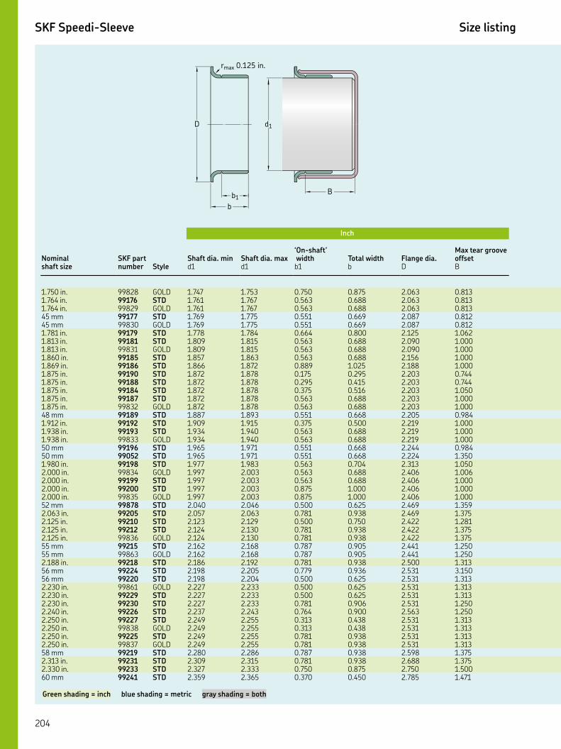
SKF Speedi-Sleeve Size listing
Inch
Nominal shaft size
SKF part number Style
Shaft dia. min Shaft dia. max‘ On-shaft’ width Total width Flange dia.
Max tear groove offset
d d b b D B
. in. GOLD . . . . . .. in. STD . . . . . .. in. GOLD . . . . . . mm STD . . . . . . mm GOLD . . . . . .. in. STD . . . . . .. in. STD . . . . . .. in. GOLD . . . . . .. in. STD . . . . . .. in. STD . . . . . .. in. STD . . . . . .. in. STD . . . . . .. in. STD . . . . . .. in. STD . . . . . .. in. GOLD . . . . . . mm STD . . . . . .. in. STD . . . . . .. in. STD . . . . . .. in. GOLD . . . . . . mm STD . . . . . . mm STD . . . . . .. in. STD . . . . . .. in. GOLD . . . . . .. in. STD . . . . . .. in. STD . . . . . .. in. GOLD . . . . . . mm STD . . . . . .. in. STD . . . . . .. in. STD . . . . . .. in. STD . . . . . .. in. GOLD . . . . . . mm STD . . . . . . mm GOLD . . . . . .. in. STD . . . . . . mm STD . . . . . . mm STD . . . . . .. in. GOLD . . . . . .. in. STD . . . . . .. in. STD . . . . . .. in. STD . . . . . .. in. STD . . . . . .. in. GOLD . . . . . .. in. STD . . . . . .. in. GOLD . . . . . . mm STD . . . . . .. in. STD . . . . . .. in. STD . . . . . . mm STD . . . . . .
b1B
b
D d1
rmax 0.125 in.
Green shading = inch blue shading = metric gray shading = both

Key features: ▲ WasteWatcher ■ Bore-Tite ◤ SS Case ◎ SS Spring ◆ Pressure seal up to 50 psi ◇ Cover plate required
SKF Speedi-Sleeve Size listing
Metric (mm)
Shaft dia. min Shaft dia. max‘ On-shaft’ width Total width Flange dia.
Max tear groove offset
StyleSKF part number
Nominal shaft sized d b b D B
. . . . . . GOLD . in.. . . . . . STD . in.. . . . . . GOLD . in.. . . . . . STD mm. . . . . . GOLD mm. . . . . . STD . in.. . . . . . STD . in.. . . . . . GOLD . in.. . . . . . STD . in.. . . . . . STD . in.. . . . . . STD . in.. . . . . . STD . in.. . . . . . STD . in.. . . . . . STD . in.. . . . . . GOLD . in.. . . . . . STD mm. . . . . . STD . in.. . . . . . STD . in.. . . . . . GOLD . in.. . . . . . STD mm. . . . . . STD mm. . . . . . STD . in.. . . . . . GOLD . in.. . . . . . STD . in.. . . . . . STD . in.. . . . . . GOLD . in.. . . . . . STD mm. . . . . . STD . in.. . . . . . STD . in.. . . . . . STD . in.. . . . . . GOLD . in.. . . . . . STD mm. . . . . . GOLD mm. . . . . . STD . in.. . . . . . STD mm. . . . . . STD mm. . . . . . GOLD . in.. . . . . . STD . in.. . . . . . STD . in.. . . . . . STD . in.. . . . . . STD . in.. . . . . . GOLD . in.. . . . . . STD . in.. . . . . . GOLD . in.. . . . . . STD mm. . . . . . STD . in.. . . . . . STD . in.. . . . . . STD mm
b1B
b
D d1
rmax 0.125 in.

SKF Speedi-Sleeve Size listing
Inch
Nominal shaft size
SKF part number Style
Shaft dia. min Shaft dia. max‘ On-shaft’ width Total width Flange dia.
Max tear groove offset
d d b b D B
mm STD . . . . . . mm GOLD . . . . . .. in. STD . . . . . .. in. STD . . . . . .. in. STD . . . . . .. in. GOLD . . . . . . mm STD . . . . . .. in. STD . . . . . .. in. STD . . . . . .. in. STD . . . . . .. in. STD . . . . . .. in. STD . . . . . .. in. STD . . . . . .. in. GOLD . . . . . .. in. STD . . . . . . mm STD . . . . . . mm GOLD . . . . . .. in. STD . . . . . . mm STD . . . . . .. in. STD . . . . . .. in. STD . . . . . .. in. STD . . . . . .. in. STD . . . . . .. in. GOLD . . . . . . mm STD . . . . . .. in. STD . . . . . .. in. STD . . . . . .. in. STD . . . . . .. in. GOLD . . . . . .. in. STD . . . . . . mm STD . . . . . . mm STD . . . . . . mm STD . . . . . . mm GOLD . . . . . . mm STD . . . . . .. in. STD . . . . . . mm STD . . . . . . mm GOLD . . . . . .. in. STD . . . . . .. in. GOLD . . . . . .. in. STD . . . . . .. in. STD . . . . . .. in. GOLD . . . . . .. in. STD . . . . . .. in. STD . . . . . .. in. GOLD . . . . . . mm STD . . . . . . mm STD . . . . . .
b1B
b
D d1
rmax 0.125 in.
Green shading = inch blue shading = metric gray shading = both

Key features: ▲ WasteWatcher ■ Bore-Tite ◤ SS Case ◎ SS Spring ◆ Pressure seal up to 50 psi ◇ Cover plate required
SKF Speedi-Sleeve Size listing
Metric (mm)
Shaft dia. min Shaft dia. max‘ On-shaft’ width Total width Flange dia.
Max tear groove offset
StyleSKF part number
Nominal shaft sized d b b D B
. . . . . . STD mm. . . . . . GOLD mm. . . . . . STD . in.. . . . . . STD . in.. . . . . . STD . in.. . . . . . GOLD . in.. . . . . . STD mm. . . . . . STD . in.. . . . . . STD . in.. . . . . . STD . in.. . . . . . STD . in.. . . . . . STD . in.. . . . . . STD . in.. . . . . . GOLD . in.. . . . . . STD . in.. . . . . . STD mm. . . . . . GOLD mm. . . . . . STD . in.. . . . . . STD mm. . . . . . STD . in.. . . . . . STD . in.. . . . . . STD . in.. . . . . . STD . in.. . . . . . GOLD . in.. . . . . . STD mm. . . . . . STD . in.. . . . . . STD . in.. . . . . . STD . in.. . . . . . GOLD . in.. . . . . . STD . in.. . . . . . STD mm. . . . . . STD mm. . . . . . STD mm. . . . . . GOLD mm. . . . . . STD mm. . . . . . STD . in.. . . . . . STD mm. . . . . . GOLD mm. . . . . . STD . in.. . . . . . GOLD . in.. . . . . . STD . in.. . . . . . STD . in.. . . . . . GOLD . in.. . . . . . STD . in.. . . . . . STD . in.. . . . . . GOLD . in.. . . . . . STD mm. . . . . . STD mm
b1B
b
D d1
rmax 0.125 in.

SKF Speedi-Sleeve Size listing
Inch
Nominal shaft size
SKF part number Style
Shaft dia. min Shaft dia. max‘ On-shaft’ width Total width Flange dia.
Max tear groove offset
d d b b D B
mm GOLD . . . . . .. in. STD . . . . . .. in. STD . . . . . .. in. STD . . . . . .. in. STD . . . . . .. in. STD . . . . . .. in. STD . . . . . .. in. STD . . . . . .. in. GOLD . . . . . .. in. STD . . . . . . mm STD . . . . . .. in. STD . . . . . .. in. STD . . . . . .. in. GOLD . . . . . .. in. STD . . . . . . mm STD . . . . . . mm STD . . . . . . mm STD . . . . . . mm STD . . . . . .. in. STD . . . . . .. in. STD . . . . . .. in. GOLD . . . . . .. in. STD . . . . . .. in. STD . . . . . .. in. GOLD . . . . . .. in. STD . . . . . .. in. STD . . . . . .. in. STD . . . . . .. in. GOLD . . . . . . mm STD . . . . . .. in. STD . . . . . .. in. STD . . . . . .. in. STD . . . . . . mm STD . . . . . .. in. STD . . . . . .. in. STD . . . . . .. in. STD . . . . . .. in. STD . . . . . .. in. GOLD . . . . . .. in. STD . . . . . . mm STD . . . . . . mm STD . . . . . . mm STD . . . . . . mm STD . . . . . .. in. STD . . . . . . mm STD . . . . . .. in. STD . . . . . .. in. STD . . . . . .
b1B
b
D d1
rmax 0.125 in.
Green shading = inch blue shading = metric gray shading = both
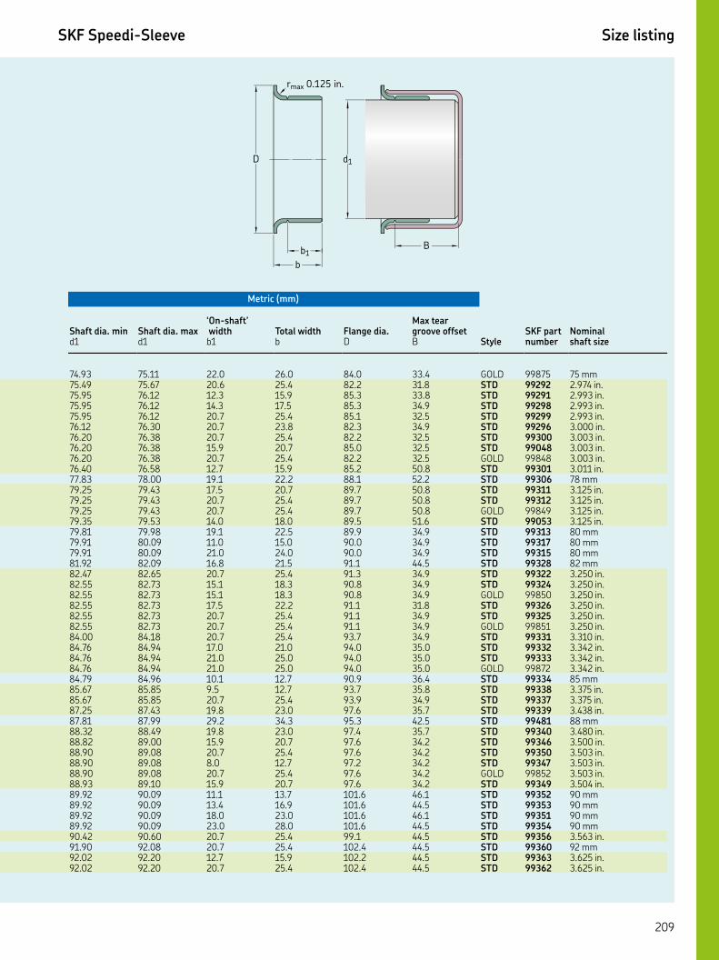
Key features: ▲ WasteWatcher ■ Bore-Tite ◤ SS Case ◎ SS Spring ◆ Pressure seal up to 50 psi ◇ Cover plate required
SKF Speedi-Sleeve Size listing
Metric (mm)
Shaft dia. min Shaft dia. max‘ On-shaft’ width Total width Flange dia.
Max tear groove offset
StyleSKF part number
Nominal shaft sized d b b D B
. . . . . . GOLD mm. . . . . . STD . in.. . . . . . STD . in.. . . . . . STD . in.. . . . . . STD . in.. . . . . . STD . in.. . . . . . STD . in.. . . . . . STD . in.. . . . . . GOLD . in.. . . . . . STD . in.. . . . . . STD mm. . . . . . STD . in.. . . . . . STD . in.. . . . . . GOLD . in.. . . . . . STD . in.. . . . . . STD mm. . . . . . STD mm. . . . . . STD mm. . . . . . STD mm. . . . . . STD . in.. . . . . . STD . in.. . . . . . GOLD . in.. . . . . . STD . in.. . . . . . STD . in.. . . . . . GOLD . in.. . . . . . STD . in.. . . . . . STD . in.. . . . . . STD . in.. . . . . . GOLD . in.. . . . . . STD mm. . . . . . STD . in.. . . . . . STD . in.. . . . . . STD . in.. . . . . . STD mm. . . . . . STD . in.. . . . . . STD . in.. . . . . . STD . in.. . . . . . STD . in.. . . . . . GOLD . in.. . . . . . STD . in.. . . . . . STD mm. . . . . . STD mm. . . . . . STD mm. . . . . . STD mm. . . . . . STD . in.. . . . . . STD mm. . . . . . STD . in.. . . . . . STD . in.
b1B
b
D d1
rmax 0.125 in.

SKF Speedi-Sleeve Size listing
Inch
Nominal shaft size
SKF part number Style
Shaft dia. min Shaft dia. max‘ On-shaft’ width Total width Flange dia.
Max tear groove offset
d d b b D B
. in. STD . . . . . .. in. STD . . . . . .. in. STD . . . . . .. in. STD . . . . . . mm STD . . . . . . mm STD . . . . . . mm STD . . . . . .. in. STD . . . . . .. in. STD . . . . . .. in. STD . . . . . .. in. GOLD . . . . . .. in. STD . . . . . .. in. STD . . . . . .. in. STD . . . . . .. in. GOLD . . . . . .. in. STD . . . . . .. in. STD . . . . . .. in. STD . . . . . .. in. STD . . . . . .. in. GOLD . . . . . . mm STD . . . . . .. in. STD . . . . . . mm STD . . . . . .. in. STD . . . . . .. in. STD . . . . . .. in. STD . . . . . . mm STD . . . . . . mm STD . . . . . .. in. STD . . . . . . mm STD . . . . . .. in. STD . . . . . .. in. STD . . . . . .. in. GOLD . . . . . . mm STD . . . . . .. in. STD . . . . . .. in. STD . . . . . .. in. STD . . . . . . mm STD . . . . . . mm STD . . . . . .. in. STD . . . . . . mm STD . . . . . .. in. STD . . . . . . mm STD . . . . . . mm STD . . . . . . mm STD . . . . . .. in. STD . . . . . .. in. GOLD . . . . . .. in. STD . . . . . .
b1B
b
D d1
rmax 0.125 in.
Green shading = inch blue shading = metric gray shading = both

Key features: ▲ WasteWatcher ■ Bore-Tite ◤ SS Case ◎ SS Spring ◆ Pressure seal up to 50 psi ◇ Cover plate required
SKF Speedi-Sleeve Size listing
Metric (mm)
Shaft dia. min Shaft dia. max‘ On-shaft’ width Total width Flange dia.
Max tear groove offset
StyleSKF part number
Nominal shaft sized d b b D B
. . . . . . STD . in.. . . . . . STD . in.. . . . . . STD . in.. . . . . . STD . in.. . . . . . STD mm. . . . . . STD mm. . . . . . STD mm. . . . . . STD . in.. . . . . . STD . in.. . . . . . STD . in.. . . . . . GOLD . in.. . . . . . STD . in.. . . . . . STD . in.. . . . . . STD . in.. . . . . . GOLD . in.. . . . . . STD . in.. . . . . . STD . in.. . . . . . STD . in.. . . . . . STD . in.. . . . . . GOLD . in.. . . . . . STD mm. . . . . . STD . in.. . . . . . STD mm. . . . . . STD . in.. . . . . . STD . in.. . . . . . STD . in.. . . . . . STD mm. . . . . . STD mm. . . . . . STD . in.. . . . . . STD mm. . . . . . STD . in.. . . . . . STD . in.. . . . . . GOLD . in.. . . . . . STD mm. . . . . . STD . in.. . . . . . STD . in.. . . . . . STD . in.. . . . . . STD mm. . . . . . STD mm. . . . . . STD . in.. . . . . . STD mm. . . . . . STD . in.. . . . . . STD mm. . . . . . STD mm. . . . . . STD mm. . . . . . STD . in.. . . . . . GOLD . in.. . . . . . STD . in.
b1B
b
D d1
rmax 0.125 in.

SKF Speedi-Sleeve Size listing
Inch
Nominal shaft size
SKF part number Style
Shaft dia. min Shaft dia. max‘ On-shaft’ width Total width Flange dia.
Max tear groove offset
d d b b D B
. in. STD . . . . . .. in. GOLD . . . . . . mm STD . . . . . . mm STD . . . . . .. in. STD . . . . . .. in. STD . . . . . .. in. STD . . . . . . mm STD . . . . . .. in. STD . . . . . .. in. STD . . . . . .. in. STD . . . . . .. in. STD . . . . . .. in. STD . . . . . .. in. GOLD . . . . . . mm STD . . . . . .. in. STD . . . . . . mm STD . . . . . .. in. STD . . . . . .. in. STD . . . . . .. in. STD . . . . . .. in. GOLD . . . . . . mm STD . . . . . .. in. STD . . . . . .. in. STD . . . . . . mm STD . . . . . . mm STD . . . . . .. in. STD . . . . . .. in. STD . . . . . . mm STD . . . . . .. in. STD . . . . . . mm STD . . . . . .. in. STD . . . . . . mm STD . . . . . .. in. STD . . . . . . mm STD . . . . . .. in. STD . . . . . . mm STD . . . . . .. in. STD . . . . . .. in. STD . . . . . .. in. STD . . . . . .. in. and mm STD . . . . . .. in. STD . . . . . .. in. STD . . . . . .
b1B
b
D d1
rmax 0.125 in.
Green shading = inch blue shading = metric gray shading = both
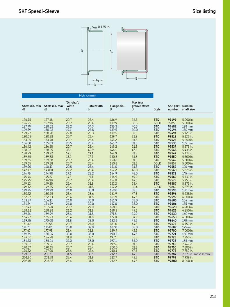
Key features: ▲ WasteWatcher ■ Bore-Tite ◤ SS Case ◎ SS Spring ◆ Pressure seal up to 50 psi ◇ Cover plate required
SKF Speedi-Sleeve Size listing
Metric (mm)
Shaft dia. min Shaft dia. max‘ On-shaft’ width Total width Flange dia.
Max tear groove offset
StyleSKF part number
Nominal shaft sized d b b D B
. . . . . . STD . in.. . . . . . GOLD . in.. . . . . . STD mm. . . . . . STD mm. . . . . . STD . in.. . . . . . STD . in.. . . . . . STD . in.. . . . . . STD mm. . . . . . STD . in.. . . . . . STD . in.. . . . . . STD . in.. . . . . . STD . in.. . . . . . STD . in.. . . . . . GOLD . in.. . . . . . STD mm. . . . . . STD . in.. . . . . . STD mm. . . . . . STD . in.. . . . . . STD . in.. . . . . . STD . in.. . . . . . GOLD . in.. . . . . . STD mm. . . . . . STD . in.. . . . . . STD . in.. . . . . . STD mm. . . . . . STD mm. . . . . . STD . in.. . . . . . STD . in.. . . . . . STD mm. . . . . . STD . in.. . . . . . STD mm. . . . . . STD . in.. . . . . . STD mm. . . . . . STD . in.. . . . . . STD mm. . . . . . STD . in.. . . . . . STD mm. . . . . . STD . in.. . . . . . STD . in.. . . . . . STD . in.. . . . . . STD . in. and mm. . . . . . STD . in.. . . . . . STD . in.
b1B
b
D d1
rmax 0.125 in.
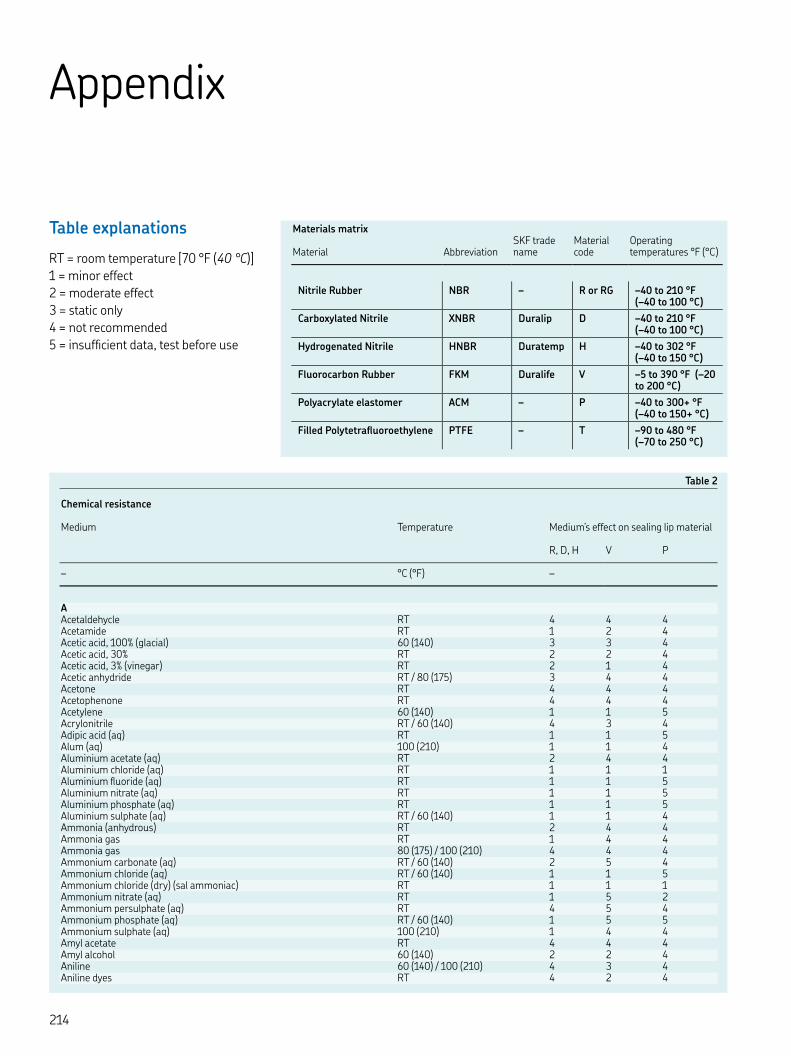
Table
Chemical resistance
Medium Temperature Medium’s effect on sealing lip material
R, D, H V P
– °C (°F) –
A Acetaldehycle RT Acetamide RT Acetic acid, % (glacial) () Acetic acid, % RT Acetic acid, % (vinegar) RT Acetic anhydride RT / () Acetone RT Acetophenone RT Acetylene () Acrylonitrile RT / () Adipic acid (aq) RT Alum (aq) () Aluminium acetate (aq) RT Aluminium chloride (aq) RT Aluminium fluoride (aq) RT Aluminium nitrate (aq) RT Aluminium phosphate (aq) RT Aluminium sulphate (aq) RT / () Ammonia (anhydrous) RT Ammonia gas RT Ammonia gas () / () Ammonium carbonate (aq) RT / () Ammonium chloride (aq) RT / () Ammonium chloride (dry) (sal ammoniac) RT Ammonium nitrate (aq) RT Ammonium persulphate (aq) RT Ammonium phosphate (aq) RT / () Ammonium sulphate (aq) () Amyl acetate RT Amyl alcohol () Aniline () / () Aniline dyes RT
Table explanations
RT = room temperature [ °F ( °C)] = minor effect = moderate effect = static only = not recommended = insufficient data, test before use
Appendix
Materials matrix
Material Abbreviation
SKF trade name
Material code
Operating temperatures °F (°C)
Nitrile Rubber NBR – R or RG – to °F (– to °C)
Carboxylated Nitrile XNBR Duralip D – to °F (– to °C)
Hydrogenated Nitrile HNBR Duratemp H – to °F (– to °C)
Fluorocarbon Rubber FKM Duralife V – to °F (– to °C)
Polyacrylate elastomer ACM – P – to + °F (– to + °C)
Filled Polytetrafluoroethylene PTFE – T – to °F (– to °C)
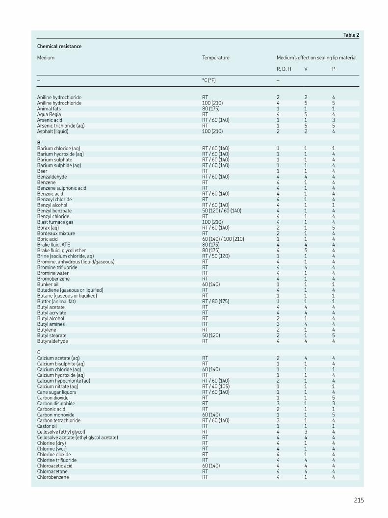
Table
Chemical resistance
Medium Temperature Medium’s effect on sealing lip material
R, D, H V P
– °C (°F) –
Aniline hydrochloride RT Aniline hydrochloride () Animal fats () Aqua Regia RT Arsenic acid RT / () Arsenic trichloride (aq) RT Asphalt (liquid) ()
BBarium chloride (aq) RT / () Barium hydroxide (aq) RT / () Barium sulphate RT / () Barium sulphide (aq) RT / () Beer RT Benzaldehyde RT / () Benzene RT Benzene sulphonic acid RT Benzoic acid RT / () Benzoyl chloride RT Benzyl alcohol RT / () Benzyl benzoate () / () Benzyl chloride RT Blast furnace gas () Borax (aq) RT / () Bordeaux mixture RT Boric acid () / () Brake fluid, ATE () Brake fluid, glycol ether () Brine (sodium chloride, aq) RT / () Bromine, anhydrous (liquid/gaseous) RT Bromine trifluoride RT Bromine water RT Bromobenzene RT Bunker oil () Butadiene (gaseous or liquified) RT Butane (gaseous or liquified) RT Butter (animal fat) RT / () Butyl acetate RT Butyl acrylate RT Butyl alcohol RT Butyl amines RT Butylene RT Butyl stearate () Butyraldehyde RT
CCalcium acetate (aq) RT Calcium bisulphite (aq) RT Calcium chloride (aq) () Calcium hydroxide (aq) RT Calcium hypochlorite (aq) RT / () Calcium nitrate (aq) RT / () Cane sugar liquors RT / () Carbon dioxide RT Carbon disulphide RT Carbonic acid RT Carbon monoxide () Carbon tetrachloride RT / () Castor oil RT Cellosolve (ethyl glycol) RT Cellosolve acetate (ethyl glycol acetate) RT Chlorine (dry) RT Chlorine (wet) RT Chlorine dioxide RT Chlorine trifluoride RT Chloroacetic acid () Chloroacetone RT Chlorobenzene RT

Table
Chemical resistance
Medium Temperature Medium’s effect on sealing lip material
R, D, H V P
– °C (°F) –
Chlorobromomethane RT Chlorobutadiene RT Chloroform RT Chlorosulphonic acid RT Chlorotoluene RT Chromic acid () Citric acid () / () Cobalt chloride (aq) RT Coconut oil () / () Cod liver oil RT Coke oven gas () Copper acetate (aq) RT Copper chloride (aq) RT Copper sulphate (aq) () Corn oil RT / () Cottonseed oil RT / () Cresol () / () Cumene (isopropylbenzene) RT Cyclohexane RT Cyciohexanol RT Cyclohexanone RT p-Cymene RT
DDecahydronaphthalene (decalin) RT / () Detergent RT Developing fluids (photography) RT Diacetone alcohol RT Dibenzyl ether RT Dibutyl amine RT Dibutyl ether RT Dibutyl phthalate RT / () Dibutyl sebacate RT / () o-Dichlorobenzene RT Dicyclohexylamine RT Diethyl amine RT Diethyl benzene RT Diethyl ether RT Diethyl sebacate RT Diisopropyl benzene RT Dimethyl aniline (Xylidine) RT Dimethyl ether RT Dimethyl formamide RT / () Dimethyl phthalate RT Dioctyl phthalate RT / () Dioctyl sebacate RT / () Dioxane RT / () Dioxolane RT Dipentene RT Diphenyl oxide RT Dowtherm oils () Dry cleaning fluids ()
EEpichlorohydrin RT Ethane RT Ethanol (denatured alcohol) RT Ethanolamine (monoethanolamine) RT Ethanolamine (di- and triethanolamine) () Ethyl acetate RT Ethyl acrylate RT Ethyl benzene RT Ethyl benzoate RT Ethyl chloride RT Ethylene RT Ethylene chloride RT Ethylene chlorohydrin RT Ethylene diamine RT

Table
Chemical resistance
Medium Temperature Medium’s effect on sealing lip material
R, D, H V P
– °C (°F) –
Ethylene glycol RT Ethylene glycol () Ethylene oxide RT Ethylene trichloride RT Ethyl ether RT Ethyl formate RT Ethyl glycol (Cellosolve) RT Ethyl glycol acetate (Cellosolve acetate) RT Ethyl silicate RT
FFatty acids () Ferric chloride (aq) RT Ferric nitrate (aq) RT Ferric sulphate (aq) RT Fish oil RT Fluorine (liquified) RT Fluorobenzene RT Fluorosilic acid () Formaldehyde RT Formaldehyde, % below () Formic acid RT / ()
Fuels– Aero engine fuels JP:– JP (MIL-J- G) RT – JP (MIL-J- G) RT – JP (MIL-J- G) RT – JP (MIL-F- B) RT / () – ASTM reference fuels:– ASTM-A (MIL-S- B Typ ) RT / () – ASTM-B (MIL-S- B Typ ) RT / () – ASTM-C RT / () – Diesel fuel () – Fuel oil () – Gasohol (% ethanol or methanol) RT – Kerosene RT – Mineral oil () – Petrol RT Fumaric acid RT Furan RT Furfural RT Furfuran RT
GGelatine (aq) () Glucose RT Glue RT Glycerin () Glycols ()
Hn-Hexaldehyde RT Hexane RT / () -Hexene RT Hexyl alcohol RT Hydraulic fluids– Hydraulic oils (acc. to DIN ) () – Hydraulic fluids (acc to DIN ):– HFA (oil in water emulsion) () – HFB (water in oil emulsion) () – HFC (aqueous Polymer solutions) () – HFD (phosphoric esters) () / – Skydrol () – Skydrol () Hydrazine RT Hydrobromic acid RT / () Hydrochloric acid (conc.) RT
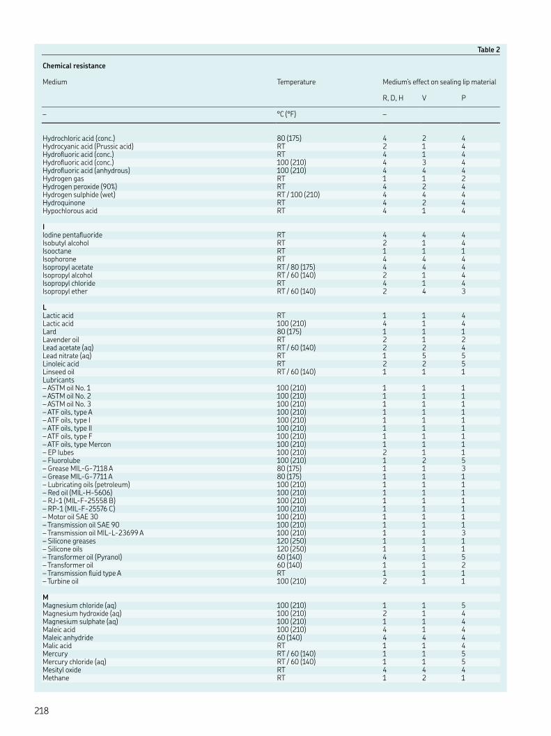
Table
Chemical resistance
Medium Temperature Medium’s effect on sealing lip material
R, D, H V P
– °C (°F) –
Hydrochloric acid (conc.) () Hydrocyanic acid (Prussic acid) RT Hydrofluoric acid (conc.) RT Hydrofluoric acid (conc.) () Hydrofluoric acid (anhydrous) () Hydrogen gas RT Hydrogen peroxide (%) RT Hydrogen sulphide (wet) RT / () Hydroquinone RT Hypochlorous acid RT
IIodine pentafluoride RT Isobutyl alcohol RT Isooctane RT Isophorone RT Isopropyl acetate RT / () Isopropyl alcohol RT / () Isopropyl chloride RT Isopropyl ether RT / ()
LLactic acid RT Lactic acid () Lard () Lavender oil RT Lead acetate (aq) RT / () Lead nitrate (aq) RT Linoleic acid RT Linseed oil RT / () Lubricants– ASTM oil No. () – ASTM oil No. () – ASTM oil No. () – ATF oils, type A () – ATF oils, type I () – ATF oils, type II () – ATF oils, type F () – ATF oils, type Mercon () – EP lubes () – Fluorolube () – Grease MIL-G- A () – Grease MIL-G- A () – Lubricating oils (petroleum) () – Red oil (MIL-H-) () – RJ- (MIL-F- B) () – RP- (MIL-F- C) () – Motor oil SAE () – Transmission oil SAE () – Transmission oil MIL-L- A () – Silicone greases () – Silicone oils () – Transformer oil (Pyranol) () – Transformer oil () – Transmission fluid type A RT – Turbine oil ()
MMagnesium chloride (aq) () Magnesium hydroxide (aq) () Magnesium sulphate (aq) () Maleic acid () Maleic anhydride () Malic acid RT Mercury RT / () Mercury chloride (aq) RT / () Mesityl oxide RT Methane RT

Table
Chemical resistance
Medium Temperature Medium’s effect on sealing lip material
R, D, H V P
– °C (°F) –
Methanol (methyl alcohol) () Methyl acetate RT Methyl acrylate RT Methyl aniline RT Methyl bromide RT Methyl cellosolve (methyl glycol) RT Methyl chloride RT Methyl cyclopentane RT Methylene chloride RT Methyl ethyl ketone RT Methyl formate RT Methyl glycol (Cellosolve) RT Methyl isobutyl ketone RT Methyl methacrylate RT Methyl salicylate RT Milk RT Mustard gas RT
NNaphtha RT Naphthalene () Naphthalenic acid RT Natural gas RT Neat-s-foot oil RT / () Nickel acetate (aq) RT Nickel chloride RT Nickel sulphate (aq) RT / () Nitric acid (conc.) RT Nitric acid (fuming) RT Nitric acid (dilute) RT Nitrobenzene () Nitroethane RT Nitrogen RT Nitrogen tetroxide RT Nitromethane RT Octadecane RT / () n-Octane RT Octyl alcohol RT Oleic acid () Olive oil () Oxalic acid () Oxygen RT Oxygen > () Ozone RT
PPalmitic acid () Peanut oil RT / () Perchloric acid RT Perchloroethylene RT / () Petroleum below () Petroleum above () Petroleum ether RT / () Petroleum gas (liquified) RT Phenol () / () Phenyl ethyl ether RT Phenyl hydrazine RT / () Phoron (diisopropylidene acetone) () Phosphoric acid, % () / () Phosphoric acid, % () / () Phosphorus trichloride RT Pickling solution RT Picric acid RT Pinene RT Pine oil RT Piperidine RT Potassium acetate (aq) RT

Table
Chemical resistance
Medium Temperature Medium’s effect on sealing lip material
R, D, H V P
– °C (°F) –
Potassium chloride (aq) RT / () Potassium cyanide (aq) RT / () Potassium dichromate (aq) RT Potassium hydroxide (aq) () Potassium nitrate (aq) RT / () Potassium sulfate (aq) RT / () Propane RT Propyl acetate RT Propyl alcohol RT / () Propylene RT Propylene oxide RT Prussic acid (hydrocyanic acid) RT Pyridine RT Pyroligneous acid RT Pyrrole RT
RRapeseed oil RT Refrigerants (acc. to DIN )– R RT – R RT – R RT – R B RT – R RT – R RT – R RT – R RT – R RT – R RT – R RT – R RT – R B RT – R RT – R C RT
SSalicylic acid RT Sea water RT Silver nitrate (aq) RT Soap solution RT Sodium acetate (aq) RT Sodium bicarbonate (aq) () Sodium bisulphite (aq) () Sodium carbonate (soda) RT / () Sodium chloride (aq) RT / () Sodium cyanide (aq) RT Sodium hydroxide (aq) RT Sodium hypochlorite (aq) RT / () Sodium metaphosphate RT / () Sodium nitrate (aq) RT / () Sodium phosphate (aq) RT / () Sodium silicate (aq) RT / () Sodium sulphate (aq) (Glauber’s salt) RT / () Sodium thiosulphate (aq) RT / () Soyabean oil RT Stannic chloride (aq) RT / () Stannous chloride (aq) RT / () Steam below () Steam above () Stearic acid () Stoddard solvent RT Styrene RT Sucrose solution RT / () Sulphur RT / () Sulphur chloride (aq) RT Sulphur dioxide (dry) RT / () Sulphur dioxide (liquified) RT / () Sulphur dioxide (wet) RT / ()
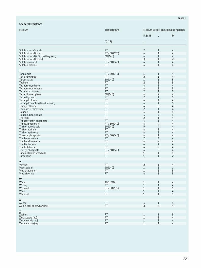
Table
Chemical resistance
Medium Temperature Medium’s effect on sealing lip material
R, D, H V P
– °C (°F) –
Sulphur hexafluoride RT Sulphuric acid (conc.) RT / () Sulphuric acid (%) (battery acid) () Sulphuric acid (dilute) RT Sulphurous acid RT / () Sulphur trioxide RT
TTannic acid RT / () Tar, bituminous RT Tartaric acid () Tepineol RT Tetrabromoethane RT Tetrabromomethane RT Tetrabutyl titanate RT Tetrachloroethylene () Tetraethyl lead RT Tetrahydrofuran RT Tetrahydronaphthalene (Tetralin) RT Thionyl chloride RT Titanium tetrachloride RT Toluene RT Toluene diisocyanate RT Triacetin RT Tributoxy ethyl phosphate RT Tributyl phosphate RT / () Trichloroacetic acid () Trichloroethane RT Trichloroethylene RT Tricresyl phosphate RT / () Triethanol amine RT Triethyl aluminium RT Triethyl borane RT Trinitrotoluene RT Trioctyl phosphate RT / () Tung oil (China wood oil) RT Turpentine RT
VVarnish RT Vegetable oil () Vinyl acetylene RT Vinyl chloride RT
WWater () Whisky RT White oil RT / () Wine RT Wood oil RT
XXylene RT Xylidine (di-methyl aniline) RT
ZZeolites RT Zinc acetate (aq) RT Zinc chloride (aq) RT Zinc sulphate (aq) RT

Seal request form
Customer to Quote: _____________________________________________ Contact: _________________________________________
End Customer: _________________________________________________ Contact: _________________________________________
Seal Brand and Part #: ___________________________________________________________________________________________
Application: _______________________________________________________________________________________________________
Purchase QTY: Delivery Date: Profile:
Annual Usage: Target Price: Material:
Reason for Inquiry:
q Delivery q Mounting q Quality q Material q New Design
q Seal Life q Wear q Leakage q Price Other:
Seal Type: q Piston Seal q Rod Seal q Guide Ring q O-Ring q Rotary Shaft Seal
q Wiper q Backup Ring q Gasket q Check if Split Other:
Motion: q Static q Oscillating q Linear ( q Single Acting q Double Acting )
Rotating ( q Clockwise* q Counter-clockwise* q Bi-directional ) q Shaft Rotating q Bore Rotating
Internal Media: (Type, Level) _________________________________________________________________________________________
External Media: (Type, Level) _________________________________________________________________________________________
Operating Conditions (Label Units)
Speed (fpm, m/s, rpm)
Differential Pressure (PSI/BAR)
Temperature (°F/°C)
Minimum
Normal
Maximum
Housing Type: q Through q Press-in q Open End q 2 Piece q Groove q Snap-in
MM q IN q Key Values Tolerance Fixed (Yes/No) Hardness Surface Finish Material
Shaft / Rod / Groove DIA d
Shaft / Rod / Groove DIA d1
Bore / Groove DIA D
Bore / Groove DIA D1
Bore / Groove Length L
Bore / Groove Length L1
Max. Extrusion Gap (Air) eMAX
Shaft Dynamic Shaft to Bore AxialTreatment Run-out Misalignment Free Play
Additional information (quality requirements, installation method, torque, pressure cycle, contamination, etc.):
Service life (h)
Cycles/min
Stroke length or Degrees of arc
Hardware Image No. (Page 2)
* Viewed from air side
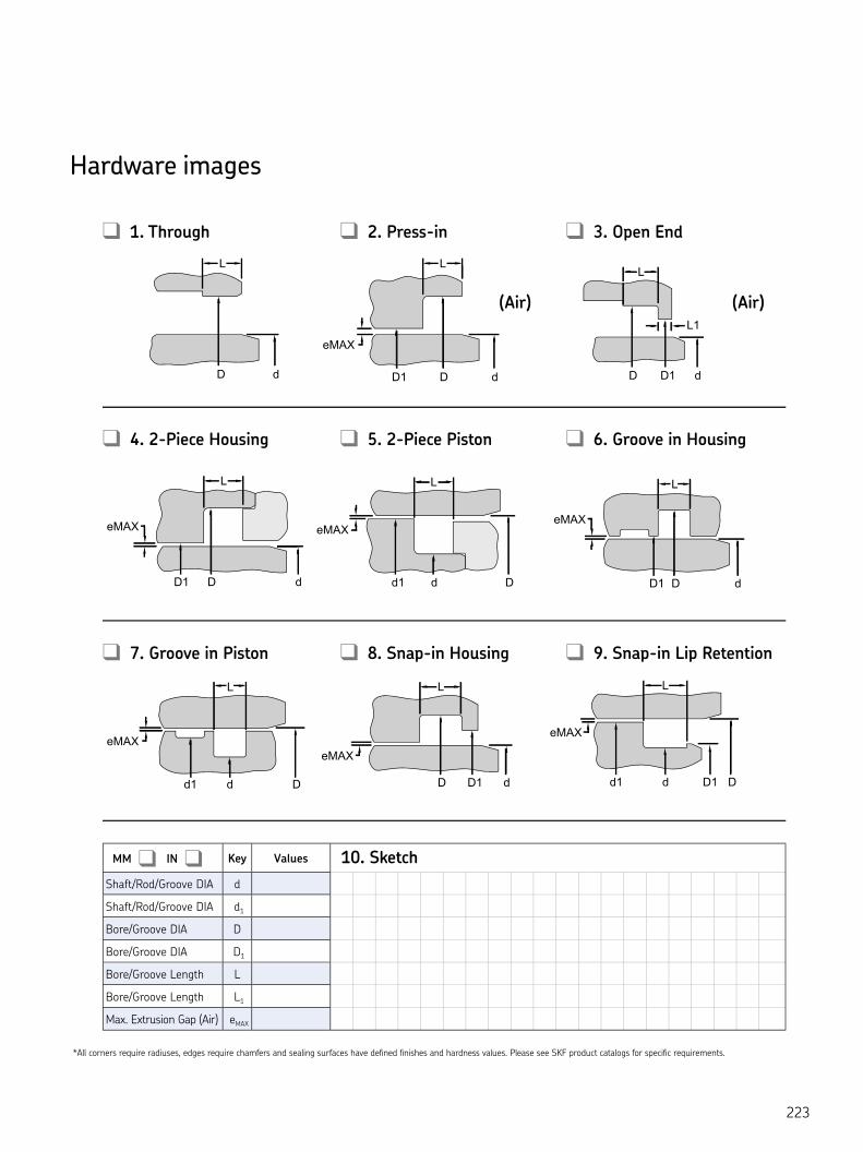
Hardware images
eMAX
D1
L1
D d
L
d D
L L L
L
D dD1
L
d Dd1DD1 d
L L
DD1 d
eMAXeMAX
L
L
LL
eMAX
dd1 D
eMAX
L
eMAX
d1 d DD dD1
LL
D1
eMAX
MM q IN q Key Values
Shaft/Rod/Groove DIA d
Shaft/Rod/Groove DIA d1
Bore/Groove DIA D
Bore/Groove DIA D1
Bore/Groove Length L
Bore/Groove Length L1
Max. Extrusion Gap (Air) eMAX
q 1. Through q 2. Press-in q 3. Open End
q 7. Groove in Piston q 8. Snap-in Housing q 9. Snap-in Lip Retention
q 4. 2-Piece Housing q 5. 2-Piece Piston q 6. Groove in Housing
(Air)(Air)
* All corners require radiuses, edges require chamfers and sealing surfaces have defined finishes and hardness values. Please see SKF product catalogs for specific requirements.
10. Sketch

CR
Seals h
andbook
skf.com | skfusa.com/industrialseals | skf.com/crseals
® SKF, CR Seals, SCOTSEAL, DURATEMP, SPEEDI-SLEEVE, WAVE, ECOPUR, H-ECOPUR, G-ECOPUR and S-ECOPUR are registered trademarks of the SKF Group.
™ EDGE, FLEX, DURALIFE and DURALIP are trademarks of the SKF Group.
© SKF USA Inc. 2018The contents of this publication are the copyright of the publisher and may not be reproduced (even extracts) unless prior written permission is granted. Every care has been taken to ensure the accuracy of the information contained in this publication but no liability can be accepted for any loss or damage whether direct, indirect or consequential arising out of the use of the information contained herein.
PUB 810-701 · 5M/CW January 2019 Printed in U.S.A.
Certain image(s) used under license from Shutterstock.com.