cracking assessment in concrete structures by …
TRANSCRIPT

CRACKING ASSESSMENT IN CONCRETE STRUCTURES BY DISTRIBUTED
OPTICAL FIBER
ABSTRACT
In this paper, a method to obtain crack initiation, location and width in concrete
structures subjected to bending and instrumented with an OBR system (Optical
Backscattered Reflectometer) is proposed. Continuous strain data with high spatial
resolution and accuracy are the main advantages of the OBR system. These
characteristics make this Structural Health Monitoring (SHM) technique a useful tool
in early damage detection in important structural problems. In the specific case of
reinforced concrete structures, which exhibit cracks even in-service loading, the
possibility to obtain strain data with high spatial resolution is a main issue. In this way,
this information is of paramount importance concerning the durability and long
performance and management of concrete structures.
The proposed method is based on the results of a test up to failure carried out on a
reinforced concrete slab. Using test data and different crack modelling criteria in
concrete structures, simple non-linear finite element models were elaborated to validate
its use in the localization and appraisal of the crack width in the testing slab.
KEYWORDS : Distributed Optical Fiber Sensor, Non-linear FEM,Cracking detection.
INTRODUCTION
Structural Health Monitoring (SHM) can be described as a process of implementing a damage
identification strategy1. In the specific case of concrete structures, damage is closely related to the
presence of cracks. Because of inherent weakness in tension, cracks can be observed in reinforced
concrete structures even in-service loading. On the other hand, cracks usually appear in concrete
surfaces due to the corrosion of the passive and active reinforcement. Therefore, early detection of

damage, its localization and characterization (crack width) are very important parameters in the
safety, maintenance and durability of concrete structures.
The crack width measurement is a main issue in damage detection. Visible cracks not only affect
the aesthetics, cracks of excessive widths can contribute to the corrosion of the reinforcement2.
Early detection of these cracks before they become visible is of high interest for a correct preventive
maintenance of concrete structures.
Until recently, conventional monitoring methods that were used to perform crack detection had
serious limitations. The most common was to perform visual inspections and /or to use discrete
sensors that generally were not able to locate existing cracks. In fact, the use of discrete sensors has
very serious limitations since it is not known a priori where the crack could appear. The main
problem is not being able to locate and especially to quantify cracking patterns in a timely manner.
During the past decades, the development of structural monitoring has produced a wide variety of
measurement systems and new sensors. Monitoring systems with more compact sizes, easy
installation and use, but especially with new measurement capabilities, have been implemented.
Within this diversity, monitoring systems based on the use of fiber optic sensors have gained an
important place and their use is increasingly being accepted. Their advantages and limitations
regarding the use of traditional mechanical and electrical sensors have been widely discussed in a
number of publications on this subject.3, 4, 5
One of the new possibilities has been to use the optical fiber itself not only as a conductive medium
of information, but as a sensitive mean to gather information. Considering this idea, the optical fiber
becomes a sensor with thousands of measurement points, giving the user the possibility of obtaining
measurements distributed along a certain length. This has led to monitoring systems with distributed
optical fiber, having the possibility to detect, localize and measure with high precision and in a
timely manner, the damage on a monitored structure. 6, 7

In the specific case of concrete structures, much of the structural damage that is to be identified is
manifested by the appearance of cracks. This is why to detect, to locate and mainly to obtain the
crack width becomes of greater relevance. Crack width can be also related to damage due to
corrosion in the reinforcing steel8. However, since the appearance of cracks is a phenomenon that
cannot be predicted a priori, very often evaluating their effects is complicated and costly when
using traditional techniques. The possibility to have monitoring systems that allow to accurately
locate and to obtain crack width dimensions has become a challenge.
This paper presents a method to obtain the average crack width in concrete structures subjected to
bending. The proposed method is based on information acquired from a monitoring system with
distributed optical fiber and is an extension of the method as presented in Rodriguez et al9. In fact,
in the presented paper, the technique to assess the crack width is introduced. Additionally, an
extensive comparison between the results of the proposed method and those obtained with other
experimental techniques and FEM models is provided, including the compression zone. In this way,
the checking of the results becomes more reliable.
AVAILABLE METHODS FOR CRACK WIDTH MEASUREMENT
Visual Inspection
Visual inspection is generally performed by using simple measuring devices, which have
predetermined ranges of crack width measurements. Occasionally, these devices have lens that
serve to amplify and improve the viewer’s vision.10
Image Processing
Currently, techniques to acquire crack patterns through images are widely used, such as high-
resolution photographic cameras and software development, allowing imaging processing. These
techniques have allowed the incorporation of monitoring systems whose application to experimental

testing in the laboratory, as well as in the field, is beginning.11
Irrespective of the characteristics of
these monitoring systems, in most cases, it is necessary to implement sophisticated methodologies
to ensure the usefulness of the acquired images.12
In the case of obtaining crack widths in concrete structures, a very important aspect is the setting of
the camera monitoring system, since when using the images to determine crack widths within
millimeter levels; it must be ensured that the reference is always the same. This aspect may limit the
use of these systems only for the measurement of cracks in small areas, or its use in laboratory tests,
where work conditions and lighting can be controlled in a more optimal manner. In field
applications, the versatility of these systems is limited because they must adapt to a number of
conditions which are often very different, as well as aspects of lighting and weather conditions.
Smart film Technique
Another possibility that currently exists for measuring crack widths in concrete structures is through
the technique known as Smart film.13
This technique is based on the simulation of the sensitivity of
the skin of an animal, when creating a surface made from enameled copper wires, which intersect
each other to simulate a sensory system. The smart film adheres to the surface of concrete with
epoxy resin. Once the smart film is adhered to the concrete surface under study, through an
electrical signal processor and a sophisticated algorithm for interpretation, the produced signals
within the smart film that run through the enameled copper wire, are monitored. When a crack in
the concrete appears, it is detected by the system and can be localized. This technique has been
tested both the laboratory and an in-service bridge.13
The results obtained so far, have been the
product of a series of major adjustments in the surface that simulates the sensory system. However,
these results seem to be still limited to the detection and localization of cracks in sections with low
length, without even quantifying crack widths.

Distributed optical Fiber
Several experiences have demonstrated the feasibility of using the Distributed Optical Fiber Sensor
system (DOFSs) and OBR (Optical Backscattered Reflectometer) technique in the structural health
monitoring of existing concrete structures.14, 15, 16
This Structural Health Monitoring (SHM)
technique has shown to be very effective in the detection and localization of initiating cracking in
the concrete, either because of the increasing applied external loads or because of environmental
actions as corrosion. Also, the distributed strain data has been used to calculate the deflection in
selected points of a bridge.15
However, the continuous (in space) monitoring of the strain along the
optical fiber, including the crossing of a crack provides additional information that can be used in
further SHM applications. Billon et al. 17
presented a methodology to perform a quantitative strain
measurement with DOFSs when strain in the optical fiber may differ from actual strain in the
structure, due to shear transfer through the intermediate material layers between the optical fiber
and the host material. Hoult and Regier18
investigated the feasibility of distributed fiber optic strain
sensors installed either internally or externally to detect pitting corrosion in reinforced concrete
beams. Their tests show how localised deterioration can be detected and quantified with embedded
sensing fibres. Rodriguez et al.9 showed how the experimental strains data obtained with and OBR
measuring system can be used to locate cracking before being visually observable. In the present
paper, it is described how these data can be used to obtain crack width. This information is of
paramount importance concerning durability and long term performance of concrete structures.
OPTICAL BACKSCATTERED REFLECTOMETER
A DOFSs is usually applied by measuring physical changes along the length of a sensing fiber. This
is a distinctive property of DOFSs with respect to other measuring techniques, because it can
replace a several number of discrete sensors. DOFSs are generally based on the measuring of some
perturbations induced on the light that travels inside the fiber. In this intrinsic mechanism, three

main physical principles take place in an optical fiber: Raman, Brillouin and Rayleigh scattering.
Raman and Brillouin processes present dependence to external physical fields. Raman scattering has
an intrinsic dependence on the temperature of the fiber, which has been used in DOFSs to perform
continuous measurement of temperature with high accuracy. Brillouin scattering is simultaneously
sensitive to strain and temperature, therefore, these two parameters could be obtained through this
scattering process19
.
However, there are two techniques based on Brillouin scattering: Brillouin Optical Time Domain
Reflectometry (BOTDR) based on a Spontaneous Brillouin scattering and Brillouin Optical Time
Domain Analysis (BOTDA) based on Stimulated Brillouin scattering20
. The main difference
between them is that BOTDA is achieved by using two optical waves (pump and probe signal). The
interaction between them, leads to a larger scattering efficiency, resulting in an energy transfer and
an amplification of the probe signal7. Therefore, these systems are used to monitor in very long
distances, up to some kilometers.21
However, they have limitations in detecting very small cracks
and in accurately providing the size of the crack.22, 23
Conversely, Rayleigh scattering in optical fiber is independent of almost any external physical field
for a wide range of condition. DOFSs based on Rayleigh technique, scattering is used only to detect
propagation effects as attenuation or gain, phase interference and polarization variation, which are
the real sensing mechanisms19
. In the specific case of DOFSs for strain and temperature monitoring,
phase interference is the physical phenomenon used to the implementation of the monitoring system
based on Rayleigh scattering process24
.
Recently, the Rayleigh scattering has been applied to the measurement of strain and temperature
with a spatial resolution around millimeters 25
. The main issue is the use of the so-called Optical
Backscattered Reflectometry (OBR). OBR is based on a frequency-domain technique, optical
frequency-domain reflectometry (OFDR) that uses a tunable laser and an interferometer to probe
reflections. Frequency domain techniques are usually used to analyse systems on the component-or
module-level when very high resolution (microns) analysis of the reflections in a system is required.
Optical backscatter differs from other frequency-domain techniques in that is sensitive enough to
measure levels of Rayleigh backscatter in standard single mode fiber. The OBR uses swept
wavelength interferometry (SWI) to measure the Rayleigh backscatter as a function of length in an
optical fiber with high spatial resolution (at a strain and temperature resolution as fine as 1
microstrain and 0.1 °C). An external stimulus (like a strain or temperature change) causes temporal
and spectral shifts in the local Rayleigh backscatter pattern. These temporal and spectral shifts can
be measured and scaled to give a distributed temperature or strain measurement16
.
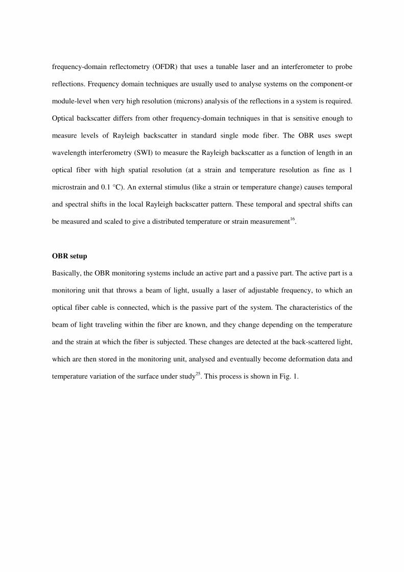
OBR setup
Basically, the OBR monitoring systems include an active part and a passive part. The active part is a
monitoring unit that throws a beam of light, usually a laser of adjustable frequency, to which an
optical fiber cable is connected, which is the passive part of the system. The characteristics of the
beam of light traveling within the fiber are known, and they change depending on the temperature
and the strain at which the fiber is subjected. These changes are detected at the back-scattered light,
which are then stored in the monitoring unit, analysed and eventually become deformation data and
temperature variation of the surface under study25
. This process is shown in Fig. 1.

Fig. 1. Rayleigh scattering measurement process.25
The specifications of the monitoring system as used in the tests presented in the next section are as
follows: Spatial resolution: Sub-millimeter spatial resolution (default gauge length 1 cm), Accuracy
in strain measurement: +/- 2 microstrain, +/- 2º C, Interval between measurement points: 1 cm,
Length range of sensor: 50 m
As shown in the following section, the availability of a continuous measurement of the strain along
a concrete surface, including the presence of cracking, can be used to warn about the initiation of
cracking, its location and the assessment of crack width.
EXPERIMENTAL VALIDATION
The OBR measuring system was deployed in a concrete slab of an experimental campaign
conducted at the Structural Technology Laboratory of the Technical University of Catalonia (UPC-
BARCELONATECH) 26, 27
. Dimensions of the reinforced concrete slab were 5.6 m span length,
1.60 m width and 0.285 m thickness. The slab was simply supported at both ends and the loading
was applied using an actuator of 1 MN capacity in the mid-span of the slab. The slab was monitored
with OBR sensors at the top and bottom surfaces, exactly in the four stretches as shown in Fig. 2.
The optical fiber used was a single-mode fiber (SMF) type with a 50 m length. A coating of a
polymer (polyimide) was used to protect the fiber against scratches and environmental attack.
Firstly, bond areas were cleaned and free from grease. A commercial glue was applied to the bond
Interrogation
System

area (on the concrete surfaces), avoiding to apply adhesive excess. The glue used was a one part
component (without mixing) chemical type ethyl cyanoacrylate, with low viscosity. The adhesive
was applied to one of the bond surfaces, avoiding the use of tissue or a brush to spread the adhesive.
The slab was also monitored in the reinforcing steel bars with dynamic strain gauges. Deflection
was measured at the centre and ends of the slab using linear displacement transducers (LVDT).
Joint opening at the middle of the slab was measured from their initiation using magnetic transducer
“Temposonics” as seen in Fig. 2 (right).
Fig. 2. Load arrangement and location of OBR sensors (left: top view, right: bottom view).
Strain Distribution
During the test, the strain distribution along the slab was measured by the OBR system. The
measured results in the third and fourth stretch at the bottom of the slab at different load levels
(from 50 kN to 110 kN with increments of 20 kN) are shown in Figs. 3 and 4. The measurements
are in good agreement with the results predicted by the analysis, and apparent strain distribution
peaks appear first at 50 kN (corresponding to the theoretical cracking load), around the middle of
the span. The location of the peaks corresponds quite well to the crack location visually observed.
Based on these data and other experimental results coming from the standard monitoring by strain-
gages and LVDT, firstly a method to obtain the mean crack width of reinforced slab is developed.
Then, three non-linear finite element models of the slab were proposed and calibrated with the

objective to obtain the most accurate model to predict cracking patterns where no instrumentation
was deployed in the test.
Fig. 3. Strain along the fiber length (third stretch bottom side) from 50 kN to 170 kN.

Fig. 4. Strain along the fiber length (fourth stretch bottom side) from 50 kN to 170 kN.
CRACK WIDTH ASSESSEMT
By obtaining the strain in the concrete surface along the fiber, a formulation can be drawn to obtain
the average crack width. The formulation is based on integrating the distribution of the experimental
strains registered along a characteristic length L. As described in Fig. 5, in order to integrate and
obtain an average strain (εmean), the strain distribution (εOBR) is defined from a strain value
corresponding to the tensile strength of the concrete (εfct ). This is the strain value where the crack
appears. Under this criterion, firstly an average deformation from the area under the curve of the
total strain over the cracked length L is defined according to equation 1(see Fig. 5). L corresponds
to the length of the element where εOBR > εfct .

Fig. 5. Definition of parameters to calculate the crack width
Ɛ���� � 1� Ɛ�����1�
�
�
This average strain has two components: the deformation to the concrete cracking and starting here,
the deformation due to the cracks in the cracked area. Therefore, from equation (2) we can calculate
Σw, where w comprises the sum of the widths of all cracks in the cracked area.
Ɛ���� � Ɛ��� �∑�� �2�
In this way, we can define an average crack width in the following way:
����� �∑�� �3�
Being N the number of cracks. N can be also obtained from the test results, counting the peaks in
the strain profile ( see Fig. 5).
The method can be applied to different load levels in order to know the variation of crack width as a
function of the load increase. A comparison between the average crack width obtained
experimentally in the middle of the span by the crack width transducers and those obtained with the
equations 1 to 3 for different load levels registered with the OBR system is shown in Table 1. The

values of columns 2 and 3 in the Table 1 are the values of the transducers 1 and 2, respectively.
These transducers are located in two different points of the cross-section, close to the edge of the
slab one, and in the central part the other (see Figs. 2 and 6). For this reason, in column 4 the mean
of these values is calculated, as representative of the crack width in the section under investigation.
It should be noticed that this comparison is done only at mid-span because this was the only section
instrumented with sensors to measure crack opening as show in Fig. 6. The results show a quite
acceptable correspondence between the experimental results and the proposed method.
Table 1. Crack width at mid-span.
Load
(kN)
Crack Width
Transducer1
(mm)
Crack Width
Transducer2
(mm)
Arithmetic
Mean
(mm)
OBR
Stretch3
(mm)
OBR
Stretch4
(mm)
50 0.058 0.099 0.079 0.062 0.065
70 0.077 0.154 0.116 0.112 0.101
90 0.105 0.125 0.115 0.149 0.127
110 0.166 0.147 0.157 0.190 0.163
130 0.296 0.200 0.248 0.237 0.209
150 0.370 0.267 0.319 0.298 0.246
170 0.439 0.337 0.388 0.354 0.213
Fig. 6. Location of transducers 1 and 2 (left: front of the slab, right: bottom and middle of the slab).

NON-LINEAR FINITE ELEMENT MODEL
As mentioned, crack width at mid-span of the slab was measured using two magnetic transducers
(Fig. 6). Therefore, a direct comparison between crack width obtained with transducers and OBR
respectively, can only be checked at these points. For this reason, a Finite Element Model (FEM)
able to represent the behaviour of cracked concrete was built and calibrated using the available
experimental data coming from the displacement transducers and strain gauges. With the results
from the FEM, more conclusions can be drawn on the performance of the optical fiber sensor in
other cross-sections different from the mid-span.
The cracked behavior of reinforced concrete structures may be modelled by discrete or smeared
crack models. In the first case, the element remains always continuous and without damage. The
cracks are modelled by displacement discontinuities between elements. In this way, the cracks can
only be developed through the element boundaries, and to obtain the direction of crack propagation,
the FEM mesh has to be progressively adapted or interface elements have to be used. The analyses
with these models becomes very cumbersome and therefore are used to follow the propagation of
singular cracks, but are not normally used to model a global crack pattern.
The smeared crack models are defined by: a failure criteria (constant or linear), a transfer across the
crack (total, constant or variable) and a law to smooth the material behavior ( brittle, linear,
exponential). The cracked material is worked out as continuous and the discontinuity of the
displacement field due to cracking is extended over the whole element. Therefore, these models are
a non-discrete global approximation to a process that is essentially discrete. However, they derive
acceptable results in practical applications28, 29
. This approach is useful because does not impose any
cracking direction. These models can be fixed or with rotation. In the first case, the cracking

direction is the same during the all computational process (bending cracks). In the second case, they
allow the co-rotation of the principal strain axes (shear-bending cracks) 29
.
The concrete slab is modelled with 2D plain stress elements, with a total of 821 nodes and 239
square elements with 9 Gauss points. The reinforcing bars are modelled by elements with perimeter
and sectional area identical to the real re-bars. The upper and bottom reinforcements consists of 7
bars each, with 16 and 20 mm diameter respectively. The concrete cover is 30 mm. (see Fig. 7) The
steel yield strength is 550 MPa. The concrete properties are those obtained in the tests26
. The
compressive strength is fc=51.31 MPa, and the tensile strength ft=4.00 MPa. The elasticity modulus
is 33,147 MPa.
Fig. 7. Mesh of Finite Element Model.
When the sensing cable is protected with a significant coating and attached to the surface with
adhesive layers, strain profiles measured in the optical fiber may differ from actual strain in the
structure. In these cases, fiber optic sensor needs to be evaluated to provide accurate measurements.
Several mechanical testing, pull out tests and FEM numerical modelling had been developed to
validate different methodologies to evaluate these effects17, 30
.
In the present case, the FEM model does not include the fiber stretches because the optic sensor
used in the test, was a fiber of 0.2 mm of diameter with a simply polyimide-coated, without any
special protective coating in the sensing cable. The fiber optic used in the test is shown in Fig. 8.
Due to the reduced dimensions of the fiber and de adhesive layer, they were not included in the
modelling.

Fig. 8. View of fiber optic sensor and layer of adhesive
The DIANA software31
is used to model the test with 3 different scenarios : brittle behavior of
concrete (Fig. 9 left) with rotating cracks (FEM1) or fixed cracks (FEM2), and tensile strength with
exponential decrease (Fig. 9 center) (FEM3). In all cases the stress-strain law in compression is
according to Spanish Code32
adjusted by a multi-linear law (Fig. 9 right).
Results: model calibration
In table 2, the measured deflections are presented in the mid-span section and those coming from
the three FEM models. The models FEM1 and FEM2 give very accurate results. The results are
graphically displayed in Fig. 10. Fig. 11 shows the results obtained in each load step by the 3
models. It is clearly visible the change of stiffness at the level of 50 kN for FEM1 and FEM2, which
corresponds to the appearance of the first cracks. In FEM3 cracking appears at around 100 kN,
despite the deflection at failure becomes more similar to the other 2 models. Based on the results of
deflection, model FEM3 is disregarded from future comparisons.

Fig. 9. Tension and compression behaviour of concrete for FEM models
Table 2. Deflections at mid-span
Load
(kN)
Experimental
Deflection
(mm)
FEM 1
Deflection
(mm)
FEM 2
Deflection
(mm)
FEM 3
Deflection
(mm)
20 0.498 0.584 0.584 0.584
60 3.833 3.53 3.53 1.752
100 10.166 11.38 10.5 5.548
140 16.543 18.10 16.7 14.01
180 22.324 25.11 22.6 21.31
204-220 29.227 29.3 29.3 29.3
Fig. 10. Experimental and FEM deflections
Fig. 11. FEM max deflections in the middle of the slab
brittle exponential multilinear
0
50
100
150
200
250
0 5 10 15 20 25 30 35
Load
(k
N)
Deflection (mm)
EXPERIMENTAL TEST
FEM2
FEM1
FEM3
0
50
100
150
200
250
0 5 10 15 20 25 30 35
Loa
d (k
N)
Desplacement (mm)
FEM1 FEM2 FEM3

Crack pattern, location and width
Fig. 12 shows the strain obtained in the first stretch (upper part of the slab, compression zone) of
the sensor and their comparison with the results obtained with FEM2 for 2 load levels. For the load
level of 50 kN, the maximum experimental value (222 µε ) is slightly higher than the theoretical one
( 190 µε ). For the load level of 110 kN, the corresponding values are 410 and 455 µε. From figure
12, we may conclude that the comparison is acceptable in the whole fiber length. The maximum
measured compressive strain in the concrete for a load level of 243 kN was 2400 µε. This value is
close to the maximum compressive strain in concrete (between 2000 and 3500 µε ), what reflects
the fact that the failure mode of the slab was due to failure in compression of the concrete at a load
level of 255 kN.
Fig. 12. Comparison of experimental and theoretical compression strain along span
Tables 3 and 4 show the strains measured by the OBR system and those predicted by the FEM
models at those points where cracking appeared (peaks) for load levels of 50 and 110 kN. The first
column in the tables indicates the location of each observed crack in the test. A value equal to zero
in table 3 means that the corresponding crack had not yet appeared for this level of load.

From tables 3 and 4, one may conclude that the best approximation to the real strains is obtained
with model FEM2 (crack pattern without rotation), as expected for a test zone mainly in bending. In
Fig. 13 we can see the comparison between the experimental crack pattern and the one obtained
with FEM2 for a load level of 110 kN at mid-span. In Fig. 14, the experimental and theoretical
(FEM2) strain laws are compared for two levels of load, showing a good fit. This confirms again the
correct performance of the OBR system in measuring strain even in cracked zones. The theoretical
values are obtained linking the points of cracking strain at the Gauss points of interpolation and
taking into account the dimension of the corresponding finite element. The location of these points
in the model is the closest to the peaks of strain identified in the test. The OBR system detected an
early cracking at low level of load around 50 kN. The crack width could be experimentally obtained
by the standard instrumentation but only in the points where the sensors were deployed (mid-span).
These values are shown in table 5 for different load levels and compared with the values obtained
with the OBR system and the theoretical models FEM1 and FEM2. Again FEM2 provides the most
accurate results.
Table 3. Micro strains at 50 kN
Peaks:distance
from the left end
(mm)
µεµεµεµε
OBR
µεµεµεµε
FEM1
µεµεµεµε
FEM2
1953 0 0 0
2258 400 594 997
2456 1300 741 1134
2758 800 570 997
2932 1480 567 1223
2991 0 0 0
3185 1090 699 997
3382 1500 587 1223
3525 0 0 0
3795 0 0 0
4066 0 0 0
4270 0 0 0

Table 4. Micro strains at 110 kN
Peaks: distance
from the left end
(mm)
µεµεµεµε
OBR
µεµεµεµε
FEM1
µεµεµεµε
FEM2
1953 800 2950 1814
2258 2250 3002 1910
2456 2450 2963 1385
2758 2590 2279 2086
2932 2040 2324 2091
2991 1550 1201 2962
3185 3450 2326 2126
3382 3500 802 2369
3525 2650 966 2962
3795 2240 2129 2022
4066 1700 1295 2031
4270 675 700 1090
Fig. 13. Comparison of experimental and theoretical crack patterns at mid-span

Fig. 14. Comparison of experimental and theoretical strain along span
Table 5. Crack width at mid-span
CONCLUSIONS
With the use of the monitoring systems with distributed optical fiber, the limitations of discrete
sensors to locate cracks and measure their width are covered, since such sensors have to rely on the
extrapolation of results and in some cases on the use of very sophisticated structural analysis
techniques to diagnose the local and global state of a whole structure.
Load
Load(kN)
Crack Width
Transducers
(mm)
Crack Witdth
OBR
(mm)
Crack Width FEM1
(mm)
Crack Width
FEM2
(mm)
50 0.079 0.062 0.049 0.052
60 0.094 --- 0.070 0.106
70 0.116 0.112 0.132 0.138
90 0.115 0.149 0.126 0.118
100 0.130 --- 0.174 0.152
111 0.157 0.190 0.202 0.206
130 0.248 0.237 0.230 0.240
140 0.284 --- 0.245 0.259
150 0.319 0.298 0.304 0.296
170 0.388 0.354 0.422 0.371
180 0.420 --- 0.482 0.409
220 0.594 --- 0.552 0.533
0
200
400
600
800
1000
1200
1400
1600
0 1000 2000 3000 4000 5000
Str
ain
(m
icro
stra
in)
Fiber Length (mm)
LOAD 50 kN
OBR
FEM2
0
500
1000
1500
2000
2500
3000
3500
4000
0 1000 2000 3000 4000 5000
Str
ain
(m
icro
stra
in)
Fiber Length (m)
LOAD 110 kN
OBR
FEM2

The experimental data obtained in the test allowed to calibrate a non-linear model for the concrete
slab. Once calibrated, the model can be used to predict cracking location and width in different parts
of the specimen. This is demonstrated by comparison with the experimental results.
The OBR system deployed allowed to predict the formation of the initial cracking, the location of
the cracks and also their width based on the continuous monitoring of strain along the optical fiber.
The obtained results compare very well with the available experimental values obtained from the
rest of the sensors as well as with the visual inspection and the values predicted by the non-linear
finite element models. This validates the use of OBR system as a method for SHM of concrete
structures.
REFERENCES
1. Liu Y and Nayak S. Structural Health Monitoring: State of the Art and Perspectives. JOM, Vol.
64 No.7, 2012.Published on line July 10, 2012.
2. Coronelli D, Hanjari K.Z and Lundgren K. Severely Corroded RC with Cover Cracking.
Journal of Structural Engineering. ASCE pp 221-232, February 2013.
3. Casas JR and Cruz JS. Fiber Optic Sensors for Bridge Monitoring. ASCE Journal of Bridge
Engineering, 8 (6), pp 362-373, November/December 2003.
4. Culshaw B. Fiber Optic Sensors in Smart Structures: Achievements, Challenges and Prospects.
SPIE Vol. 7982. Smart Sensor Phenomena, Technology, Networks and Systems. 798202-1
798202-9, 2011.
5. Glisic B and Inaudi D. Fibre optic methods for structural health monitoring. Chichester, UK:
John Wyley & Sons 2007.
6. Ravet F, Briffod F, Glisic B, Nikles M and Inaudi D. Submillimeter Crack Detection With
Brillouin-Based Fiber-Optic Sensors. IEEE Sensors Journal. Vol. 9, No. 11, November 2009.
7. Glisic B, Inaudi D. Development of method for in-service crack detection based on distributed
fiber optic sensors. Structural Health Monitoring 11 (2) pp 161-171, 2011.

8. Vidal T, Castel A, François R. Analyzing crack width to predict corrosion in reinforced
concrete. Cement and Concrete Research. 34 pp 165-174, 2004.
9. Rodriguez G, Casas JR and Villalba S. Assessing cracking characteristics of concrete structures
by Distributed Optical Fiber and Non-Linear Finite Element Modelling. EWSHM-7th European
Workshop on Structural Health Monitoring, Nantes France, July 2014.
10. D.J Haavik. Evaluating concrete cracking by measuring crack width. Publication #C900553.
The Aberdeen Group. 1990.
11. Nazmul I and Matsumoto T. High Resolution COD image analysis for health monitoring of
reinforced concrete structures through inverse analysis. International Journal Solids Structures.
45 pp159-174, 2008.
12. Jahanshani MR, Masri SF and Sukhatme S. Multi-image stitching and scene reconstruction for
evaluating defect evolution in structures. Structural Health Monitoring International journal,
10 pp 643-57, 2011.
13. Zhang B, Wang S, Li X, Zhang X, Yang G and Qiu M. Crack width monitoring of concrete
structures based on smart film. Smart Materials and Structures 23, 2014.
14. Villalba S and Casas JR. Monitorización y salud estructural. Aplicación de la fibra óptica
distribuida (OBR) en estructuras de hormigón. V Congreso de Puentes y Estructuras de ACHE.
Barcelona, España, Octubre 2011.
15. Villalba V, Casas JR and Villalba S. Application of OBR fiber optic technology in structural
health monitoring of Can Fatjó Viaduct (Cerdanyola de Vallés-Spain).VI International
Conference on Bridge Maintenance, Safety and Management, IABMAS 12, Stresa, Italy, July
2012.
16. Villalba S and Casas JR. Application of optical fiber distributed sensing to health monitoring of
concrete structures. Mechanical Systems and Signal Processing. 39 :441-451, 2013.

17. Billon A, Henault JM, Quiertant M, Taillade F, Khadour A, Martin RP, Benzarti K.
Quantitative Strain Measurements with Distributed Fiber Optic Systems: Qualification of a
Sensing Cable Bonded to the Surface of a Concrete Structure. EWSHM-7th European Workshop
on Structural Health Monitoring, Nantes France, July 2014.
18. Hoult A. and Regier R. Concrete deterioration detection using distributed sensors. Proceedings
of the ICE- Structures and Buildings, September 2014.
19. Palmieri L and Schenato L. Distributed Optical Fiber Sensing Based on Rayleigh Scattering.
The Open Optics Journal, 7, (Suppl-1, M7)104-127, 2013.
20. Zeni L. Optical fiber distributed sensors: a tool for in-situ structural and environmental
monitoring. www.corista.eu/docs/optical_fiber.pdf
21. Enckell M, Glisic B, Myrvoll F and Bergstrand B. Evaluation of large-scale bridge strain,
temperature and crack monitoring with distributed fibre optic sensors. Journal of Civil and
Structural Health Monitoring, 1, pp 37-46, 2011.
22. Bastianini F, Matta F, Galati N and Nanni A. A Brillouin smart FRP material and strain data
post processing software for structural health monitoring through laboratory testing and field
application on a highway bridge. Smarts Structures and Materials: Nondestructive Evaluation
for Health Monitoring and Diagnostics. Proc. SPIE Vol. 5765, pp 600-611. 2005.
23. Minardo A, Persichetti G, Testa G and Zeni L.Long term structural health monitoring by
Brillouin fibre-optic sensing: a real case. Journal of Geophysics and Engineering-, 9, S64-S68.
2012.
24. Froggatt M and Moore J. High-Spatial-Resolution Distributed Strain Measurement in Optical
Fiber with Rayleigh Scatter. Appl Opt; 37(10): 1735-40, 1998
25. Samiec D. Distributed fibre-optic temperature and strain measurement with extremely high
spatial resolution. Photonik international, 2012.

26. Villalba S. Diseño y validación experimental de uniones mediante superposición de lazos de
armaduras en viaductos de hormigón de sección transversal evolutiva. Optimización del
proceso constructivo. Ph. D. Thesis. Civil Engineering Department, Technical University of
Catalonia, UPC. Barcelona, Spain, July 2010.
27. Villalba S, Casas J.R, Aparicio AC and Villalba V. New structural joint by rebar looping
applied to segmental bridge construction. Fatigue strength tests. Journal of Bridge Engineering
(ASCE), Vol. 18, N. 11, pp. 1174-1188, 2013.
28. Rots JG, Nauta P, Kusters GMA and Blaauwendraad J. Smeared crack approach and fracture
localization in concrete. HERON, Delft, v.30, n.1, 1985.
29. Rots JG and Blaauwendraad J. Crack models for concrete: discrete or smeared? Fixed,
multidirectional or rotating? HERON, Delft, v.34, n.1, 1989.
30. Li D, Ren L, Li H. Mechanical property and strain transferring mechanism in optical fiber
sensors. www.interchopen.com
31. DIANA. Finite Element Analysis. User´s Manual release 9.4.4. Analysis Procedures, 2011.
32. EHE. Normativa: Instrucción del Hormigón Estructural, Ministerio de Fomento, Madrid, 2008.