craftsman router table mk2 - farnell · pdf filecraftsman router table mk2. 1 3 4 2 5 6 8 9 7...
TRANSCRIPT

CRAFTSMAN
ROUTER
TABLE MK2

1
23 4 5 6 78 9
10
12 1311 12
-2-
CRT MK2
DESCRIPTION OF PARTS
1 Legs
2 Fixing plate
3 Table top
4 Back fence
5 Workpiece support
6 Guard
7 Tenon push block
8 Lead-on pin
9 Mitre fence
10 Switch
11 Pushstick
12 Table extensions
13 Insert rings
ITEMS ENCLOSED
1 x Table top
4 x Legs
1 x Back fence and fittings
1 x Workpiece Support and fittings
1 x Tenon Block and fittings
1 x Top guard and fittings
1 x Mitre fence
1 x No-Volt Release Switch
3 x Insert rings
2 x Table extensions
1 x Lead-on Pin
1 x Spanner (9.5mm A/F)
1 x Screw and Fittings Pack
1 x Pushstick
1 x Instructions
1 x Guarantee card

-3-
CRT MK2
SAFETY PRECAUTIONS
■ Always switch off the power and unplug therouter when changing cutters or when makingadjustments.
■ Always wear protective goggles when routing.
■ Wear sound protective ear muffs when routingfor long periods of time.
■ Always wear a dust mask. Use dust extractionequipment whenever possible.
■ Do not wear loose clothing. Make sure baggysleeves are rolled up and ties are removed.
■ Always remove spanners and hex keys fromthe workpiece before switching router on.
■ Keep hands well clear of the router cutterwhen routing.
■ Avoid accidental starting of the router. Makesure the power switch is in the ‘Off’ positionbefore plugging in and connecting to theelectrical supply.
■ Never leave the router unattended whenrunning. Always wait until the router comes toa complete stop before making adjustments.
■ Do not switch the router on with the cuttertouching the workpiece.
■ Mount the router table securely to a workbench.
■ Periodically check all nuts and bolts to makesure they are tight and secure.
Cutter Care
■ Do not drop cutters or knock them againsthard objects.
■ Cutters should be kept clean. Resin build-upshould be removed at regular intervals withResin Cleaner®. The use of a dry lubricantwill act as a preventative such as Trendicote®
PTFE spray. Do not use PTFE spray onplastic components.
■ Cutter shanks should be inserted into thecollet at least 3/4 of shank length to preventdistortion. A distorted collet should bediscarded, as it can cause vibration anddamage the shank.
■ Do not over-tighten collet as this will score theshank and create a weakness there.
■ It is also advisable to periodically check therouter collet nut for wear.
Useful Advice
■ Judge your feed rate by the sound of themotor. In time, the operator will acquire a ‘feel’for the router, and a feed speed relative to thework will come naturally. Too slow a feed willresult in burning.
■ Apply the normal precautions as with anyelectric power tool.
■ The main abuse of routing machines is theinclination for operators to overload them. Themotto is ‘Keep the revs up’. The drop inrevolutions should not exceed, if possible,more than 20% of full running speed.
■ The motor of a router is susceptible to theaccumulation of sawdust and wood chips, andshould be blown out, or ‘vacuumed’,frequently to prevent interference with normalmotor ventilation.
■ Refer to the Instruction Manual supplied withyour router for full details of it’s features andsafety information.
■ Trial cuts should be made on waste materialbefore starting any project.
■ Do not store the router on the floor, aschippings, pins or dirt can drop into the airintake of the router.
IMPORTANT:
To move table with leg stand
fitted, please lift. Do not drag.

-4-
CRT MK2
ASSEMBLY
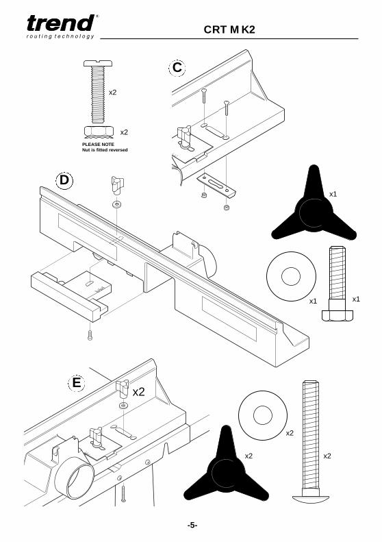
Assemble the parts as show in A to N.
For identification all fixings areillustrated as actual size.
x16
x16
x18
A
B
ACTUAL SIZE
x18
-5-
CRT MK2
x2 x2
x2
x2
C
D
Ex2
PLEASE NOTENut is fitted reversed
x1
x1x1
x2

Special note for Bosch POF routers
For the Bosch POF range of DIY routers a packing piece must be made in 3mm to 6mm thick plywood or MDF. This is then placed between the underside of the plate in the table and the underside of the router base. Thefixing screws can then be used. Enlarging theaperture in the base of the router is alsoadvised if large diameter tooling is to be used.
-6-
CRT MK2
Identification of Router Mounting
Holes and Screws (see pages 8 & 9).
■ Identify the mounting holes and fixing screws(including washers & nuts if router baserequires re-drilling) which will be required tosuit your router.
■ Identify whether your router or the fixing platerequires re-drilling.
■ Bolt the router onto the fixing plate first withthe operating controls to the front, beforefitting to the table.
■ The fixing plate is symmetrical therefore oncethe router is mounted to it, it can be fitted tothe router table in four different positions. Theorientation of the plate depends on whichrouter is fitted. It is advisable to position theplate so that controls for speed or height areeasily accessible.
IMPORTANT!
Some routers may require the
removal of the plastic base
slider to allow fitting to plate.
IMPORTANT!
Carry out the following re-
drilling only if required.
Re-drilling Router Base Only
■ Invert and stand your router onto a suitablesurface.
■ Place the fixing plate facing upwards ontothe base of your router.
■ Identify holes 1 and 2, or holes 3 on fixingplate (Ref. CRT/FP/A see page 8).
■ Fit a large diameter cutter (max. 53mm Ø)into your router and tighten collet.
■ Retract plunge mechanism and lock offallowing cutter to protrude through the base.
■ Adjust position of the fixing plate tocentralise the cutter within the centre hole.Take care not to damage cutter or to touchsharp edges.
■ Ensure that the holes you are about to drill inthe base do not interfere with any of thefeatures on the router or any webbings in thecasting of the router base. A slight turning ofthe plate may be required to miss suchobstructions.
■ Mark the centre of the holes onto the base.
■ Remove plate and mark the centre of theholes with a centre punch.
■ Drill a hole at these points with a 6mmdiameter drill bit.
■ Clean up edges of holes if required.
Re-drilling Fixing Plate Only
■ Remove the plastic base of the router.Alternatively a photocopy or an outline of thebase can be made of the plastic baseinstead.
■ Draw cross lines onto the plastic base of therouter.
■ Draw cross lines on the fixing plate with apencil. These cross lines should bisect theplate on both sides.
Packing piece

-7-
CRT MK2
■ Align the lines on the fixing plate with thoseon the plastic base and secure the fixingplate to the plastic base.
■ Using a centre punch, mark the centres ofholes.
■ Drill the required hole size with a suitablemetal cutting drill bit. Best results will beobtained if your power drill is mounted in adrill stand.
■ Countersink the hole with a countersink bitto a depth so the heads of the screws areslightly below the top surface. Clean off anyburrs created.
IMPORTANT!
If you do not have the
necessary equipment to carry
out these operations, then a
local engineering shop will be
able to carry them out
accurately for you.
Re-drilling both Fixing Plate and
Router Base
■ Invert the router and lay the fixing plate onto the upturned base.
■ Clamp the fixing plate and router basetogether with two cramps.
■ Ensuring that the drill bit will not foul anywebbing or fixtures on the router base, drillwith a 6mm diameter metal cutting drill bitinto the fixing plate and through the routerbase two holes approximately 75mm apart.
■ Unclamp the router base and fixing plate.
■ Countersink the fixing plate holes with acountersink bit to a depth so the screw headsare slightly below the top surface. Clean offany burrs created on both the fixing plate androuter base.
CL
CL

-9-
CRT MK2
11
11
9
9
10
10
11
11
13
1313
12
1212
13 14
14
MAKITA 3620 10 D x 2MAKITA 3612(C) 9 D x 2
11 A x 4MAKITA 3612BR 10 D x 2
11 A x 4MAKITA 3600B ■ D x 2
■ A x 4
CRT/FP/C CRT/FP/D
-8-
CRT MK2
4 4
4
3
311
5
5 5
52
8
8
66
67 7
7
TREND T5 1 E x 2TREND T9 1 & 2 E x 3AEG OF4505, OF500S, OFE710 3 ● G x 2ATLAS COPCO OFS720, OFSE850, OFS50
OFSE1000, OF500S 3 ● G x 2B&D KW779, 780(E), 800(E)
BD780(E) 4 A x 3B&D SR100, DN67, BD66 3 ● G x 2BOSCH POF400, 500A, 600ACE 3 F x 2BOSCH GOF1600A, 1700ACE 1 & 2 F x 3DEWALT DW613 1 E x 2DEWALT DW620, 621 1 E x 2DEWALT DW625EK 1 & 2 F x 3EINHELL EOF850SP 3 ● G x 2ELU MOF96(E) MK1 3 ● G x 2ELU MOF96(E) MK2 1 E x 2ELU OF97(E) 1 E x 2ELU MOF131, 177(E) 1 & 2 F x 3FELISATTI R346EC 1 & 2 F x 3FELISATTI TP246(E) ■ ● G x 2FERM FBF-6E, FBF-8E 3 ● G x 2FESTO OF900(E), 1000(E),
1010EBC, 2000(E) 1 & 2 ● H x 3HITACHI M8(V) 5 B x 4HITACHI FM8, ZK2008 3 ● H x 2HOLZHER 2335, 2355, 2356 ■ ● G x 2KANGO R8550S 3 ● G x 2KINZO 250C44 ■ F x 2KRESS FM6955 3 ● G x 2LYNX RT-800-A 3 ● G x 2MAFELL LO50E, 65E 1 & 2 ● H x 3MAKITA RP0910, 1110C 1 E x 2METABO OF528 3 ● G x 2METABO OF1028, OFE1229 ■ ● G x 2METABO OF1612, OFE1812 ■ ● G x 2NUTOOL NPT850 3 ● G x 2PERLES OF808(E) pre 1999 3 ● G x 2PERLES OF808(E) post 1999 1 E x 2PERFORMANCE POWER 1020W 3 ● G x 2POWER DEVIL PDW5026 3 ● G x 2ORTER CABLE 100, 690, 693 3 ● H x 2POWER DEVIL PDW5027 3 ● G x 2RYOBI R500, R502 1 & 2 ● H x 3SPARKY X52E 3 ● G x 2STAYER PR50 3 ● G x 2VIRUTEX FR77C, 78C, 66F 3 ● H x 2WADKIN R500 1 & 2 ● H x 3WICKES 900W 3 ● G x 2
BOSCH GOF900A, 900ACE, POF800ACE 6 H x 3BOSCH GOF1300ACE 7 H x 3RYOBI RE600N, R600N,RE601,R601 8 I x 2
CRT/FP/A CRT/FP/B
● Re-drilling of router base by user required■ Re-drilling of insert plate by user required* Requires 3mm packing piece
CRT/MK2
FIXING
PLATES
CUNF10-32
x3/8"
BM5x10mm
AM4x12mm
GM6x25mm
FM6x12mm
EM6x10mm
IM8x20mm
HM6x35mm
DM5x16mm
IMPORTANT!
Some routers may require the
removal of their plastic base
slider to allow fitting to the plate.
***
ATLAS COPCO OFSE2000 12 F x 3CASALS FT750, 1000E, FT2000VCE 12 F x 3DRAPER R1900V 12 F x 3FREUD FT1000E, FT2000E 12 F x 3HITACHI M12SA, M12V 13 B x 4HITACHI TR12 ■ B x 4RYOBI RE120, R150, R151, RE155K 14 D x 2PEUGEOT DF55E, DEF570E 14 B x 2SKIL 1835, 1875U1 ■ C x 3

-10-
CRT MK2
x4
x1
The fixing plate must be fitted to the routerbase before installation into the router table.
I
F
G
x1
Mounting Table to Workbench or
Workboard
The router table must be mounted onto eitherthe optional floor stand or onto a suitableworkbench or workboard.
Each table leg has four holes at the bottommounting. Firmly secure the table assembly to aworkbench or workboard, using self-tappingscrews (not provided). If a workboard is used, this will allow quickmounting and removal from a workbench byusing cramps. If a Workmate® is to be usedthen a batten can be fitted to allow securing inthe Workmate’s® jaws.
H
Workboard 575mm x 450mm Batten 560mm x 100mm
IMPORTANT:
Please tighten
screws across
the diagonals,
to ensure the
plate remains
flat. Tighten all
screws evenly.

-11-
CRT MK2
x1
x1 x1
x1
x1
x1
x1
x1
x2
x4
x2
J
K
L
-12-
CRT MK2
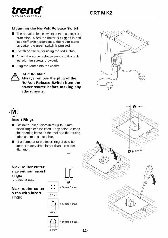
Mounting the No-Volt Release Switch
■ The no-volt release switch serves as start-upprotection. When the router is plugged in andits on/off switch depressed, the router startsonly after the green switch is pressed.
■ Switch off the router using the red button.
■ Attach the no-volt release switch to the tableleg with the screws provided.
■ Plug the router into the socket.
IMPORTANT:
Always remove the plug of the
No-Volt Release Switch from the
power source before making any
adjustments.
Ø
Ø
Insert Rings
■ For router cutter diameters up to 50mm,insert rings can be fitted. They serve to keepthe opening between the tool and the routingtable as small as possible.
■ The diameter of the insert ring should beapproximately 4mm larger than the cutterdiameter.
Max. router cutter
size without insert
rings:
- 53mm Ø max
Max. router cutter
sizes with insert
rings:32mm
= 28mm Ø max.
48mm
= 44mm Ø max.
54mm
= 50mm Ø max.
Ø
M

-13-
CRT MK2
Guard Operation
When routing with the top guard, never reachunder the guard or swing the guard away. Theguard should not be removed from the backfence and should always be used in the loweredposition.
Cutter Rotation
Feed Direction
Feed Direction
■ Always work with constant, medium rate.Feeding too slow will results in burn marksand excessive heat build up of the cutter.
■ Good results will be obtained by removingsmall amounts of material in several passes.
■ Always feed work in the opposite direction tothe direction of rotation of the router cutter.

-14-
CRT MK2
ADJUSTMENT
Fence Adjustments
To make adjustment to the lateral movement ofthe back fence:
■ Release the back fence knob.
■ Loosen the two screws that secure
the adjustable wedge.
■ Adjust position and re-tighten screws.
■ Re-tighten the back fence knob.
The back fence can be adjustedforwards and backwards, using the graduatedscales to gauge the depth of mould.
For edge moulding, position the back fence withthe fastening bolts towards the front of the slot.
For panel grooving (i.e. routing of grooves awayfrom the edge of the workpiece) the fasteningbolts should be to the rear of the holes and slots.
Workpiece Support
The workpiece support provides safe guiding ofthe workpiece when routing the complete edgeof the surface.
Adjustment range from:0 to 12.7mm (1/2”)
Cutting Depth/Cutting Height
Before starting to work:
■ Adjust the cutting depth (A) by adjusting the
position of the back fence.
■ Adjust the cutting height (B) by raising or
lowering the cutter using a fine height
adjuster (if fitted). Alternatively rapid height
adjustment can be made if a PlungeBar is
fitted.
max.58mm
32mm

-15-
CRT MK2
OPTIONAL ACCESSORIES
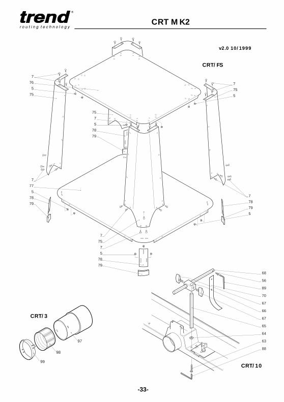
Hose and Connector - CRT/3 & CRT/4The back fence is provided with an extractionpoint for connection to suitable vacuumextractors. The internal hole diameter is 58mm(2 1/4"). Suitable fittings with 58mm outsidediameter are available for most extractor units.
■ Only a vacuum extractor unit recommendedfor use in the workshop should be used.
■ A suitable adaptor and extraction hose canbe purchased as optional accessories.
The hose (Ref. CRT/4) has an outside diameterof 39mm and inside diameter of 32mm. Thehose adaptor (Ref. CRT/3) is a three piecedesign that allows the hose to swivel freely.
■ Assemble the hose adaptor onto the end ofthe hose as shown and insert into backfence.
■ Fit the other end of the extraction hose toyour dust extractor.
39mmx 3metre
Large capacity extraction hose - T30/22
A larger 58mm diameter hose 1.5 metres longwith integral connector is available (Ref. T30/22)for fitting to the CRT and the Trend T30A vacuumextractor. This hose will provide an increased rateof air flow to improve extraction effectiveness.
■ The hose is simply inserted into the back fenceextraction point.
58mm x 1.5metre
T30/22
CRT/3
CRT/4

-16-
CRT MK2
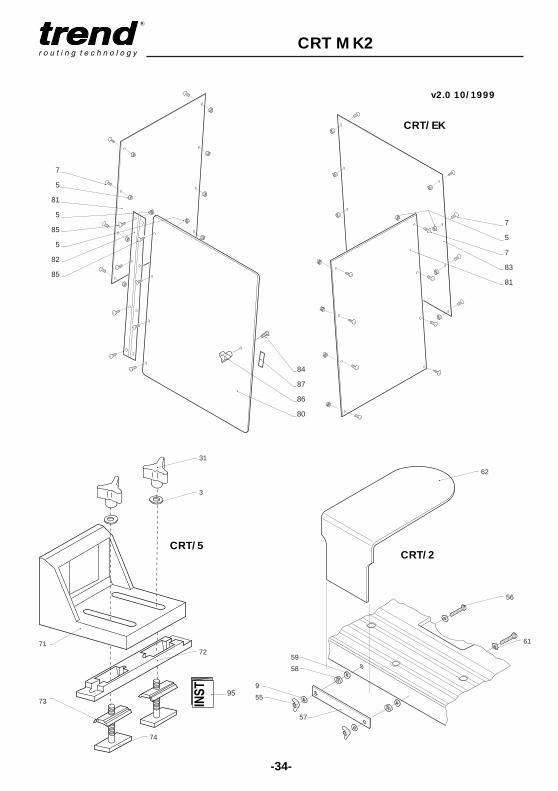
Profiling Top Guard - CRT/2
■ Remove the back fence and assemble theprofiling top guard as shown.
The use of the optional profiling top guard isrecommended when profiling of workpiecesworkpieces with a pin or ball bearing guidedcutter. It will prevent the operator's fingersinadvertently contacting the cutter whileproviding good visibility.
Pages 26 and 27 describe a typical applicationinvolving using ball bearing guided cutters withto make a shield.
Spring Pressure Clamps - CRT/10The optional spring pressure clamps can bemounted to the back fence. When adjusted tosuit the width and thickness of the workpiece,they ensure the workpiece is held down ontothe surface to obtain accurate machining ofthe workpiece.
■ Remove back fence from table surface andassemble as shown.
Adjustment
■ The spring pressure clamps will requireadjusting to suit the height and width ofworkpiece being routed.
■ The pressure strips should provide enoughpressure to prevent the workpiece liftingfrom the table surface, but not too much asto create friction which would prevent theworkpiece from sliding freely.
■ The horizontal bar with pressure strip fittedcan be removed from the vertical pillarswhen not required. The vertical pillars canbe left in position and will not impede thetenon push bock system.
CRT/10
CRT/2
-17-
CRT MK2
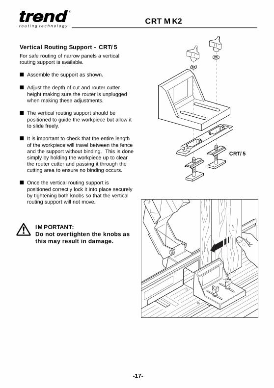
Vertical Routing Support - CRT/5
For safe routing of narrow panels a verticalrouting support is available.
■ Assemble the support as shown.
■ Adjust the depth of cut and router cutterheight making sure the router is unpluggedwhen making these adjustments.
■ The vertical routing support should bepositioned to guide the workpiece but allow itto slide freely.
■ It is important to check that the entire lengthof the workpiece will travel between the fenceand the support without binding. This is donesimply by holding the workpiece up to clearthe router cutter and passing it through thecutting area to ensure no binding occurs.
■ Once the vertical routing support ispositioned correctly lock it into place securelyby tightening both knobs so that the verticalrouting support will not move.
IMPORTANT:
Do not overtighten the knobs as
this may result in damage.
CRT/5

-18-
CRT MK2
x4
x44
x44
To adjust foruneven floors,loosen screws,raise or lower footand re-tighten.
Floor Stand - CRT/FS
Always mount the routing table on awork table, bench or on the optionalfloor stand.
IMPORTANT:
Please do not fit top screws
until CRT/MK2 is fitted to
the floor stand. Once
CRT/MK2 is placed onto
floor stand, the screws can
be fitted.
IMPORTANT:
Do not drag unit along floor. Please lift to move.

-19-
CRT MK2
Enclosure Kit - CRT/EK
x32
x32
x1
x1
x1
+-

CRT MK2
-20-
OPERATION
Edge moulding with the back fence
■ Mark the width and depth of cut requiredonto the end of the timber and place it upagainst back fence.
■ Release back fencefixing bolts andadjust position untilrequired width of cutis achieved.
If pin or ball bearingguided cutters are used,ensure that the backfence is in line with the guide or slightly behindit. The back fence will give more support andprovides the retractable safety guard andspring pressure clamp facility.
■ Lock back fence fixingbolts.
■ Release plungemechanism on routerand adjust the depthof cut using the fineheight adjuster orPlungeBar (if fitted).
■ Lock-off plunge mechanism of router.
■ Lower guard and check it will retract freelyover the workpiece.
■ Adjust the spring pressure clamps (if fitted)to suit the thickness and width of thetimber.
■ Ensure that you have the pushstick withineasy reach when routing.
■ Switch on router and pass timber overcutter with a consistent feed speed.
■ Ensure even pressure is kept on theworkpiece down onto the table and againstthe back fence.
IMPORTANT:
Before making adjustments
isolate the router and no-volt
release switch from the power
supply.
Always ensure that hands
are never near the
cutter.
Use the push stick to safely
maintain pressure on narrow
timbers.
Useful AdviceMake a test cut on a piece of waste materialprior to carrying out any routing operation.
Examples of edge moulding cutters
Craft Range Ref. C020
Craft Range Ref. C072
Craft Range Ref. C110
Craft Range Ref. C040
Craft Range Ref. C112
Craft Range Ref. C094
-21-
CRT MK2
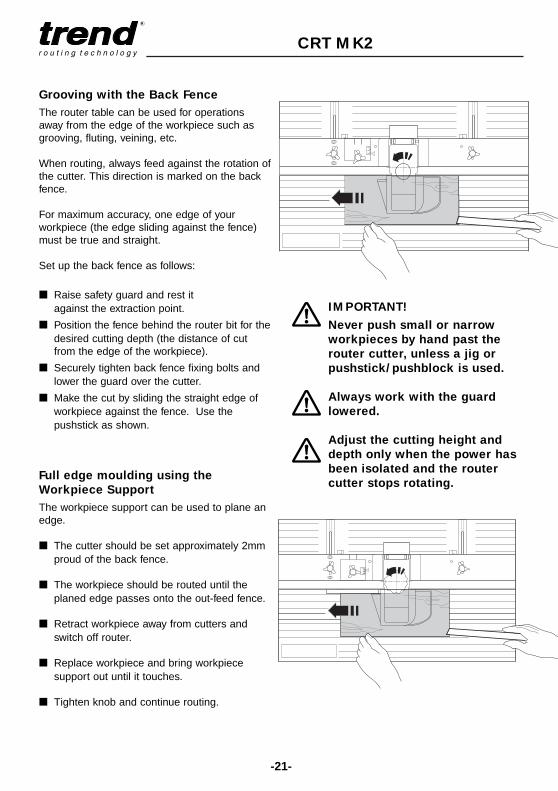
Grooving with the Back Fence
The router table can be used for operationsaway from the edge of the workpiece such asgrooving, fluting, veining, etc.
When routing, always feed against the rotation ofthe cutter. This direction is marked on the backfence.
For maximum accuracy, one edge of yourworkpiece (the edge sliding against the fence)must be true and straight.
Set up the back fence as follows:
■ Raise safety guard and rest it against the extraction point.
■ Position the fence behind the router bit for thedesired cutting depth (the distance of cutfrom the edge of the workpiece).
■ Securely tighten back fence fixing bolts andlower the guard over the cutter.
■ Make the cut by sliding the straight edge ofworkpiece against the fence. Use thepushstick as shown.
Full edge moulding using the
Workpiece Support
The workpiece support can be used to plane anedge.
■ The cutter should be set approximately 2mmproud of the back fence.
■ The workpiece should be routed until theplaned edge passes onto the out-feed fence.
■ Retract workpiece away from cutters andswitch off router.
■ Replace workpiece and bring workpiecesupport out until it touches.
■ Tighten knob and continue routing.
IMPORTANT!
Never push small or narrow
workpieces by hand past the
router cutter, unless a jig or
pushstick/pushblock is used.
Always work with the guard
lowered.
Adjust the cutting height and
depth only when the power has
been isolated and the router
cutter stops rotating.
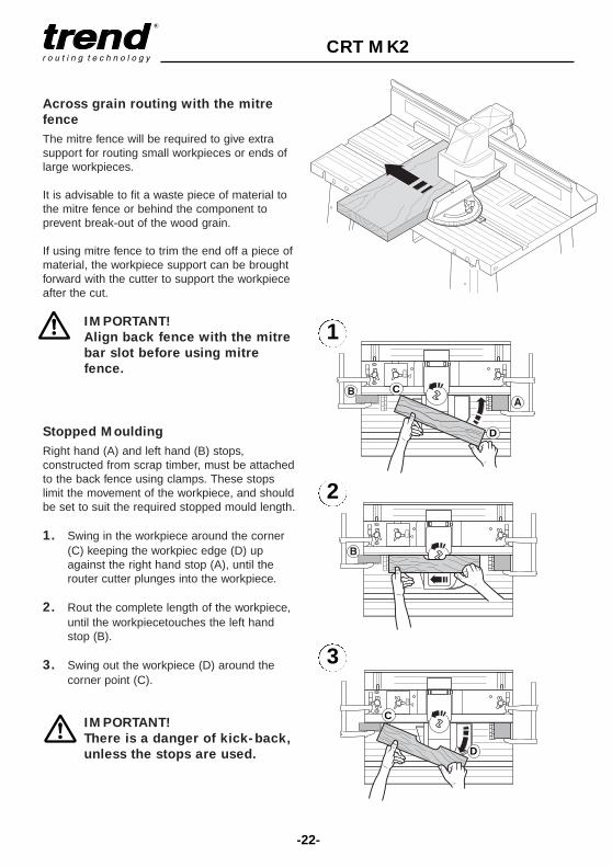
Across grain routing with the mitre
fence
The mitre fence will be required to give extrasupport for routing small workpieces or ends oflarge workpieces.
It is advisable to fit a waste piece of material tothe mitre fence or behind the component toprevent break-out of the wood grain.
If using mitre fence to trim the end off a piece ofmaterial, the workpiece support can be broughtforward with the cutter to support the workpieceafter the cut.
IMPORTANT!
Align back fence with the mitre
bar slot before using mitre
fence.
Stopped Moulding
Right hand (A) and left hand (B) stops,constructed from scrap timber, must be attachedto the back fence using clamps. These stopslimit the movement of the workpiece, and shouldbe set to suit the required stopped mould length.
1. Swing in the workpiece around the corner(C) keeping the workpiec edge (D) upagainst the right hand stop (A), until therouter cutter plunges into the workpiece.
2. Rout the complete length of the workpiece,until the workpiecetouches the left handstop (B).
3. Swing out the workpiece (D) around thecorner point (C).
IMPORTANT!
There is a danger of kick-back,
unless the stops are used.
C
D
-22-
CRT MK2
C
D
1
2
3
-23-
CRT MK2
w
w
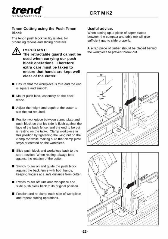
Tenon Cutting using the Push Tenon
Block
The tenon push block facility is ideal forproducing tenons and sliding dovetails.
IMPORTANT!
The retractable guard cannot be
used when carrying our push
block operations. Therefore
extra care must be taken to
ensure that hands are kept well
clear of the cutter.
■ Ensure that the workpiece is true and the endis square and smooth.
■ Mount push block assembly on the backfence.
■ Adjust the height and depth of the cutter tosuit the cut required.
■ Position workpiece between clamp plate andpush block so that it's side is flush against theface of the back fence, and the end to be cutis resting on the table. Clamp workpiece inthis position by tightening the wing nut on theclamp rod while making sure that clamp platestays orientated on the workpiece.
■ Slide push block and workpiece back to thestart position. When routing, always feedagainst the rotation of the cutter.
■ Switch router on and guide the push blockagainst the back fence with both hands,keeping fingers at a safe distance from cutter.
■ Switch router off, unclamp workpiece andslide push block back to its original position.
■ Position and re-clamp each side of workpieceand repeat cutting operations.
Useful advice.When setting up, a piece of paper placedbetween the compact and table top will givesufficient gap to slide properly.
A scrap piece of timber should be placed behindthe workpiece to prevent break-out.

-24-
CRT MK2
CRT/2
Routing without a Back Fence
IMPORTANT!
There is an increased danger of
injury since the router cutter is
freely accessible from all sides.
Fit the profiling top guard for
protection and the lead-on pin
to prevent kick-back.
■ Only use router cutters with a ball bearing orpin guide.
■ Always work against the direction of rotationof the router cutter.
Mounting a Lead-on Pin
■ The lead-on pin should be screwed into thetable top as shown and tightened with a flatscrewdriver.
The pin is used as a guide for the workpiecewhen the cut is first made. Correct workingprocedure for this is critical especially whenusing large diameter cutters.
Profiling Working Procedure
■ Switch router on and allow it to reach fullrunning speed.
■ Position the workpiece against the lead-onpin as shown. The workpiece should notcontact the cutter.
■ Gradually swing workpiece towards cutteruntil workpiece or template engages the ballbearing or pin guide.
■ Feed workpiece against the rotation of thecutter whilst swinging the workpiece awayfrom the lead-on pin. At this point the ballbearing is acting as the guide.

-25-
CRT MK2
■ Progressively feed the workpiece anti-clockwise around the shape of thetemplate ensuring that the ball bearingalways stays in contact with theworkpiece.
■ When the complete edge of theworkpiece has been machined, slide itaway from the cutter.
■ If you are unfamiliar with the aboveprocedure then the technique should bepractised before switching on the router.
Helpful Advice
■ Always keep the workpiece moving in aprecise steady movement to prevent theworkpiece from burning.
■ Never let go of the workpiece. Alwayskeep an even pressure of the workpieceagainst the bearing. Do not use toomuch pressure.
■ If you wish to stop routing halfwaythrough the operation. Simply slide theworkpiece away from the cutter beforeswitching off the router.
■ If the workpiece inadvertently comesaway from the ball-bearing and so doesnot complete the cut correctly, do notstop. Complete the operation andrepeat the procedure for the edgeconcerned.
■ It is usually advisable to repeat theoperation in order to improve the finishof the workpiece.
■ Keeps hands away from the cutter, evenif the guard is fitted, in order to give agood safety margin.
■ If natural woods are used, considerationshould be given to break-out of shortgrain which will effect your decision as towhere to start the routing operation inorder to prevent it.

-26-
CRT MK2
EXAMPLE APPLICATION
Producing a Shield
■ Construct an actual size template of thedesign from 6mm MDF or plywood ensuringthat it is accurate and free from imperfections.
■ Fix the template to the back of the workpieceto be used using screws or double sidedtape.
■ Rough cut the workpiece to the shape of thetemplate using a band saw or jigsaw leaving2-3mm oversize.
■ Fit a ball bearing guided trimmer cutter.
■ Lay the workpiece (with template fitted) facedown on the table surface. Adjust the heightof the cutter. Ensure that the ball bearing willcontact the template and the cutting edge ofthe cutter will machine the full edge of theworkpiece.
■ Fit the profiling top guard and adjust height togive a 6mm gap between the top of cutterand underside of template.
■ Switch router on and position the workpieceagainst the lead-on pin as shown. Theworkpiece should not contact the cutter.
■ Rout the shield using the proceduredescribed on the previous pages.
Useful adviceIf natural woods are used, consideration shouldbe given to break-out of short grain which willeffect your decision as to where to start therouting operation in order to prevent it.
Moulding the Shield
A suitable ball bearing guided cutter should bechosen to mould the shield.
■ Fit chosen moulding cutter and adjust heightof cutter to achieve shape required.
■ If the full edge of the workpiece is to bemachined, leave the template attached to theworkpiece so as to provide a guide for theball bearing. Otherwise the template can beremoved, providing there is sufficient edge forthe ball bearing to follow.
■ Repeat the same routing procedure asbefore.
If the profile required involves excessive removalof material, it is advisable to take two passeswith the cutter. First reduce the height of thecutter protruding from the table, this in effect,reduces the amount of material which will beremoved, or fit a larger ball bearing, if one isavailable for that particular cutter.
The second pass can then be made to give therequired finish.
Carrying out this two stage routing operation hasmany advantages.
■ Improved finish on workpiece
■ Less load on cutter and router
■ Far less risk of workpiece snatching
Definition of Snatching
This can be described as the cutter catching theworkpiece and projecting it away from thedirection of rotation. The workpiece is oftentaken from the operator's hands and projectedacross the work area. It can have potentiallydangerous consequences if the cutter isunguarded and/or the operator's hands are tooclose to the cutter. Damage to the cutter canalso be caused.
The following precautions should be made toavoid a potentially dangerous situation:
-27-
CRT MK2
Lead-onPin
Guard
Table Surface
Template
Insert Ring
6mm
Guard
Table Surface
6mmLead-onPin
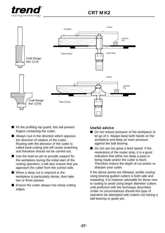
■ Fit the profiling top guard, this will preventfingers contacting the cutter.
■ Always rout in the direction which opposesthe direction of rotation of the cutter.Routing with the direction of the cutter iscalled back-cutting and will cause snatchingand therefore should not be carried out.
■ Use the lead-on pin to provide support forthe workpiece during the initial start of therouting operation, it will also ensure that youapproach the cutter from the correct side.
■ When a deep cut is required or theworkpiece is particularly dense, then taketwo or three passes.
■ Ensure the cutter always has sharp cuttingedges.
Useful advice■ Do not reduce pressure of the workpiece or
let go of it. Always keep both hands on theworkpiece and keep an even pressureagainst the ball bearing.
■ Do not use too great a feed speed. If therevolutions of the router drop, it is a goodindication that either too deep a pass isbeing made and/or the cutter is blunt.Therefore reduce the depth of cut and/or re-sharpen your cutter.
If the above points are followed, profile routingusing bearing guided cutters is both safe andrewarding. It is however advisable for those newto routing to avoid using larger diameter cuttersuntil proficient with the technique described.Under no circumstances should this type ofoperation be attempted with cutters not having aball bearing or guide pin.
Craft RangeRef. C116
Craft RangeRef. C078

-28-
CRT MK2
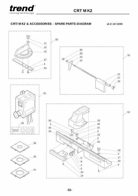
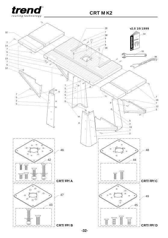
CRT/MK2 & ACCESSORIES - SPARE PARTS LIST v2.0 10/1999
Item Qty Description Ref.
1 1 Table Top WP-CRTMK2/012 2 Table Leg WP-CRTMK2/023 4 Washer 7.2mm X 19mm X 1.5mm WP-CRT/034 2 Bolt Carriage UNC1/4"-20 X 1.3/4" WP-CRT/045 34 Nut/Star Washer UNF10-30 WP-CRTMK2/056 1 Mitre Fence Bar WP-CRTMK/067 34 Machine Screw Pan UNF10-32 X 1/2" PH WP-CRTMK2/078 1 Back Fence Wedge WP-CRTMK2/089 4 Machine Screw Csk UNF10-32 X 3/4" PH WP-CRTMK2/0910 1 Mitre Fence Head WP-CRTMK2/1011 1 Mitre Fence Knob UNC10-24 WP-CRT/1112 1 Extension Table Support LH WP-CRTMK2/1213 1 Extension Table Support RH WP-CRTMK2/1314 1 Extension Table Left WP-CRTMK2/1415 1 Washer 5.2mm X 14.2mm X 1mm WP-CRT/1516 1 Extension Table Right WP-CRTMK2/1617 1 Back Fence WP-CRTMK2/1718 1 Safety Guard WP-CRTMK2/1819 1 Guard Pivot Pin WP-CRTMK2/1920 1 Workpiece Support WP-CRT/2021 1 Push Block WP-CRT/2122 1 Clamp Rod UNC5/16"-18 WP-CRT/2223 1 Clamp Plate For WP-CRT/2324 1 Bolt Hex UNC1/4"-20 X 1" WP-CRT/2425 1 Guard Pivot Pin Clip WP-CRTMK2/2526 1 Wing Nut UNC5/16"-18 WP-CRT/2627 1 Washer 9mm X 17.5mm X 1.5mm WP-CRT/2728 2 Scale Metric/Imperial WP-CRTMK2/2829 1 Washer Split Spring UNF1/4" WP-CRT/2930 3 Knob UNC1/4"-20 WP-CRTMK2/3032 1 Table Top Label WP-CRTMK2/3233 1 Label Fence Trend WP-CRTMK2/3334 1 Label Warning WP-CRTMK2/3435 2 Machine Screw Pan UNF10-32 X 7/8" PH WP-CRTMK2/3536 1 Nut Hex UNF1/4"-28 WP-CRT/3637 1 Screw Self Tapping 4.8mm x 12.7mm PH WP-CRTMK2/3738 1 Lead On Pin WP-CRTMK2/3839 1 Insert Ring 32mm ID WP-CRTMK2/3940 1 Insert Ring 48mm ID WP-CRTMK2/4041 1 Insert Ring 54mm ID WP-CRTMK2/4142 1 Fixing Pack For Plate A WP-CRTMK2/42

-29-
CRT MK2
CRT/MK2 & ACCESSORIES - SPARE PARTS LIST v2.0 10/1999
Item Qty Description Ref.
43 1 Fixing Pack For Plate B WP-CRTMK2/4344 1 Fixing Pack For Plate C WP-CRTMK2/4445 1 Fixing Pack For Plate D WP-CRTMK2/4546 0 Fixing Plate A With Screws CRT/FP/A47 0 Fixing Plate B With Screws CRT/FP/B48 0 Fixing Plate C With Screws CRT/FP/C49 0 Fixing Plate D With Screws CRT/FP/D50 0 Mitre Fence Complete WP-CRTMK2/5051 0 Push Block Complete WP-CRT/5152 0 Back Fence Complete WP-CRTMK2/5253 1 Bolt Carriage UNC10-24 X 3/4" WP-CRTMK2/5391 1 No Volt Release Switch 230v UK Plug NVRS/230V
0 No Volt Release Switch 230v Euro Plug NVRS/230V/EUR92 0 Fixing Pack For Switch WP-NVRS/0193 1 Spanner 9.5mm A/F Pressed Steel WP-SPAN/95P94 1 Manual MANU/CRT96 1 Plastic Pushstick PUSHSTICK/1
CRT/EK5 32 Nut/Star Washer UNF10-30 WP-CRTMK2/0537 1 Screw Self Tapping 4.8mm X 12.7mm PH WP-CRTMK2/3780 1 Enclosure Kit Door Panel WP-CRTMK2/8081 2 Enclosure Kit Side Panel WP-CRTMK2/8182 1 Enclosure Kit Hinge WP-CRTMK2/8283 1 Enclosure Kit Back Panel WP-CRTMK2/8385 8 Machine Screw Pan UNC10-32 X 3/8" PH WP-CRTMK2/8586 1 Enclosure Kit Knob WP-CRTMK2/8687 1 Magnetic Latch WP-CRTMK2/87
CRT/FS5 44 Nut/Star Washer UNF10-30 WP-CRTMK2/057 44 Machine Screw Pan UNF10-32 X 1/2" PH WP-CRTMK2/0775 4 Leg Stand Leg Assembly WP-CRTMK2/7576 1 Leg Stand Top Shelf WP-CRTMK2/7677 1 Leg Stand Bottom Shelf WP-CRTMK2/7778 4 Leg Stand Adjustable Foot WP-CRTMK2/7879 4 Leg Stand Rubber Foot WP-CRTMK2/79
CRT/254 2 Washer 5.3mm X 9.8mm X 1.0mm WP-WASH/0955 2 Wing Nut M5 WP-NUT/11

-30-
CRT MK2
CRT/MK2 & ACCESSORIES - SPARE PARTS LIST v2.0 10/1999
Item Qty Description Ref.
57 1 Clamping Plate WP-CRT/5758 2 Nut Hex M5 WP-NUT/0559 2 Spring Washer M5 WP-WASH/2960 2 Star Washer M5 WP-WASH/3961 2 Machine Screw Pan M5 X 20mm Slot WP-SCW/1662 1 Perspex Guard WP-CRT/62
CRT/397 1 Adaptor Tube WP-CRT/9798 1 Adaptor Fitting WP-CRT/9899 1 Adaptor Clip WP-CRT/99
CRT/53 2 Washer 7.2mm x 19mm x 1.5mm WP-CRT/0331 1 Workpiece Support Knob UNC1/4"-20 WP-CRT/3171 1 Vertical Support Fence Body Only WP-CRT/7172 1 Guide Track For Vertical Support WP-CRT/7273 2 Wedge For Vertical Support WP-CRT/7374 2 Bolt For Guide Track Vertical Supp
UNC1/4"-20 X 1.3/8" WP-CRT/7495 1 Instructions for CRT/5 INST/CRT/5
CRT/1056 2 Machine Screw Socket M5 X 10mm WP-SCW/2063 2 Machine Screw Socket M6 X 20mm WP-SCW/2964 2 Washer M6 WP-WASH/5065 2 Vertical Pillar WP-CRT/6566 2 Connecting Block WP-CRT/6667 4 Knob M6 X 10mm WP-KNOB/0168 2 Horizontal Bar WP-CRT/6870 2 Pressure Strip WP-CRT/7088 1 Hex Key 4mm A/F WP-AP/0489 1 Hex Key 3mm A/F WP-AP/03
-31-
CRT MK2
40
39
41
18
35
31
3
19
3
25
5
8
4
5
20
24
30
3
17
34
4
30
3
35
33
52
36
29
23
22
21
27
26
51
11
15
10
37
6
53
50
91
92
CRT/MK2 & ACCESSORIES - SPARE PARTS DIAGRAM v2.0 10/1999
46
42
47
43
48
44
49
45
-32-
CRT MK2
28
73891928
7167125
521372
714757
1375
12
32
7525
752575
CRT/FP/A
CRT/FP/B
CRT/FP/C
CRT/FP/D
v2.0 10/1999
96
93
CRT/MK2
94
-33-
CRT MK2
7
76
5
75
75
7
5
78
79
7
77
5
78
79
7
75
7
5
78
79
7
78
79
5
7
75
5
68
56
89
70
67
66
67
65
64
63
88
CRT/FS
CRT/10
v2.0 10/1999
97
98
99
CRT/3
-34-
CRT MK2
7
5
81
5
85
5
82
85
84
87
86
80
7
5
7
83
81
CRT/EK
31
3
7271
73
74
CRT/5
62
56
61
59
58
9
55
57
CRT/2
95
v2.0 10/1999

-35-
CRT MK2
Maintenance and Cleaning
Before all work on the router table itself, pull themains cable out of the socket and not the routercable out of the no-volt release switch.
Always keep the table clean. After operation,clean the woodchip, dust and waste away fromthe table.
Do not use PTFE spray on the plasticcomponents of the table.
Guarantee
■ The router table carries a manufacturersguarantee in accordance with the conditionson the enclosed guarantee card.
Recycling
■ Router table, accessories and packagingshould be sorted for environmentally friendlyrecycling.

Trend Machinery & Cutting Tools Ltd.Unit 6 Odhams Trading Estate Watford WD2 5TR EnglandEnquiries: _____________0800 487363Technical Support:_____01923 224681Fax: _________________01923 236879Email: [email protected]: ____________www.trendm.co.ukM
AN
U/C
RT
v4
.0
© Copyright Trend 2000. No part of this publication may be reproduced, stored or transmitted in any form without prior permission.Our policy of continuous improvement means that specifications may change without notice. Trend Machinery and Cutting Tools
cannot be held liable for any material rendered unusable or any form of consequential loss. E&OE
RECYCLABLE