crash analysis trends in the automotive industry dilip bhalsod · crash analysis trends in the...
TRANSCRIPT
Crash Analysis trends in the Automotive Industry
Dilip Bhalsod2017 3rd China LS-DYNA User’s conference
1
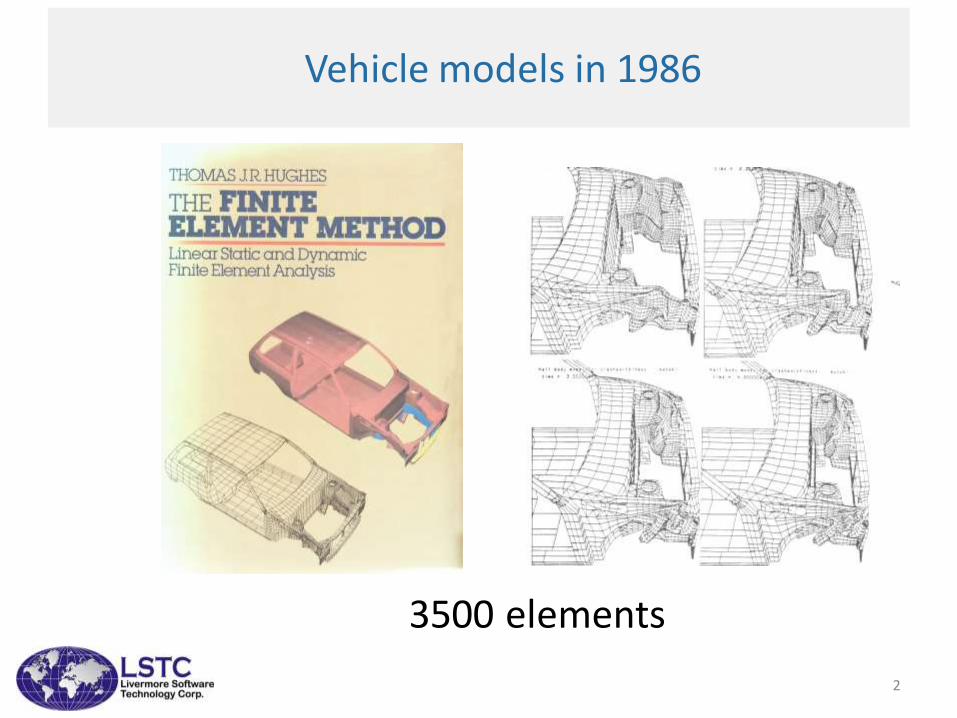
Vehicle models in 1986
3500 elements
2
3
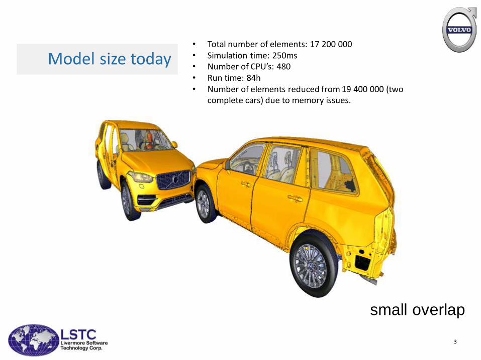
Model size today
small overlap
• Total number of elements: 17 200 000• Simulation time: 250ms • Number of CPU’s: 480• Run time: 84h• Number of elements reduced from 19 400 000 (two
complete cars) due to memory issues.
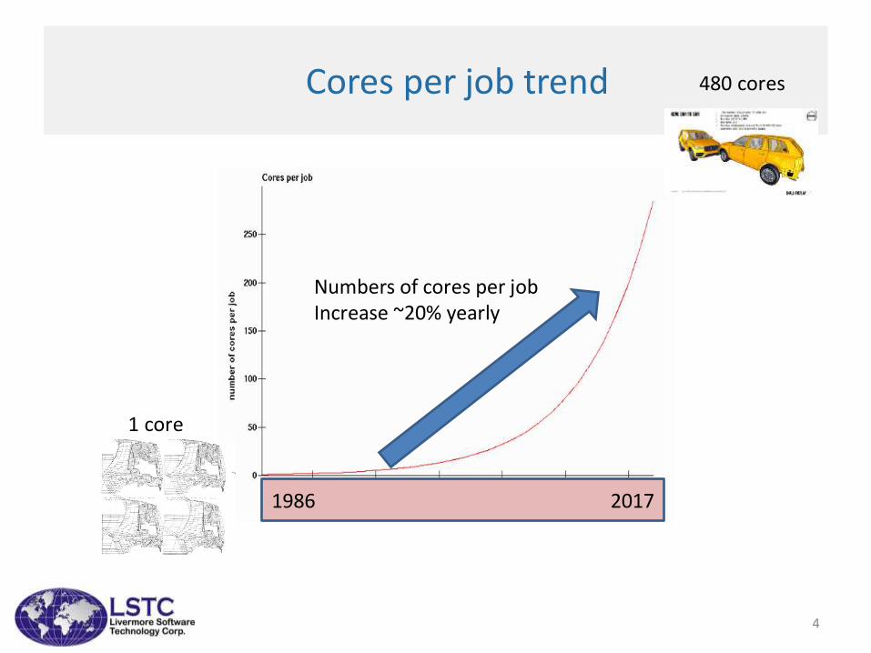
Cores per job trend
1 core
480 cores
Numbers of cores per jobIncrease ~20% yearly
1986 2017
4
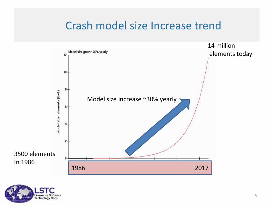
Crash model size Increase trend
Model size increase ~30% yearly
3500 elementsIn 1986
14 millionelements today
1986 2017
5
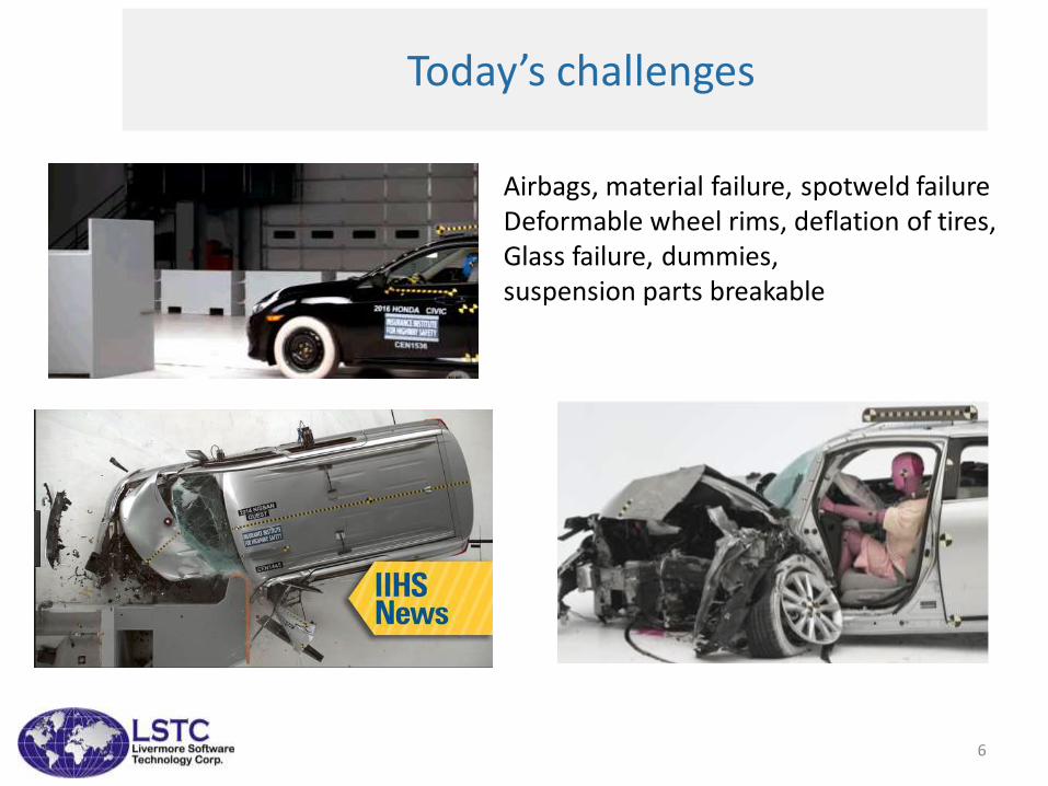
Today’s challenges
Airbags, material failure, spotweld failureDeformable wheel rims, deflation of tires,Glass failure, dummies, suspension parts breakable
6
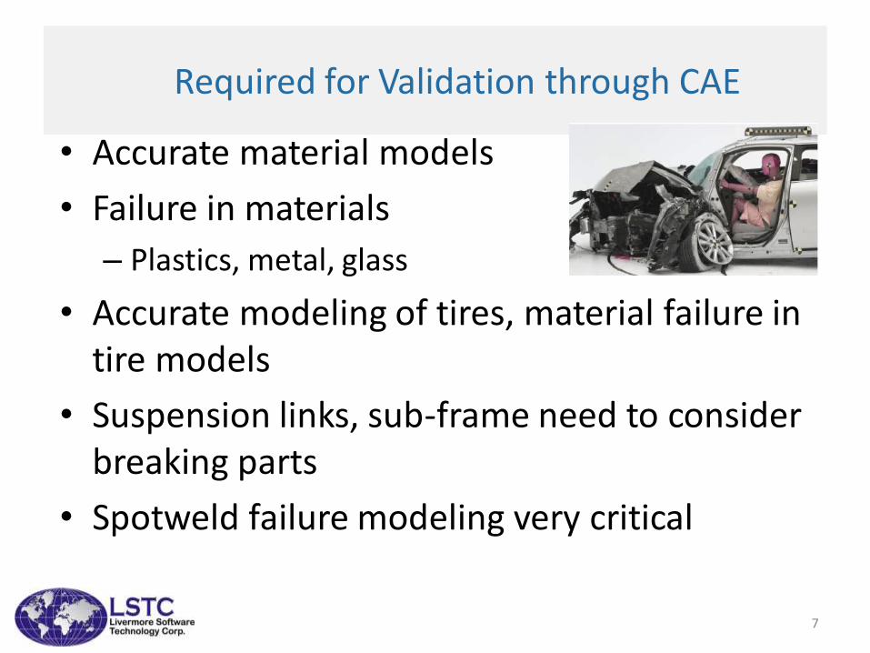
Required for Validation through CAE
• Accurate material models
• Failure in materials
– Plastics, metal, glass
• Accurate modeling of tires, material failure in tire models
• Suspension links, sub-frame need to consider breaking parts
• Spotweld failure modeling very critical
7
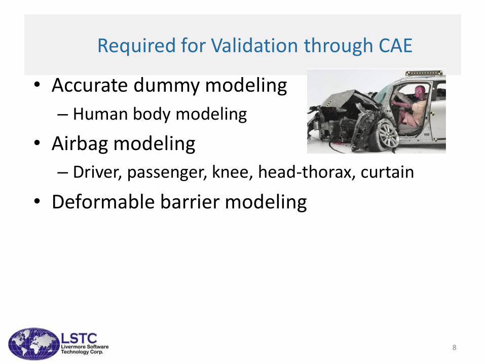
Required for Validation through CAE
• Accurate dummy modeling
– Human body modeling
• Airbag modeling
– Driver, passenger, knee, head-thorax, curtain
• Deformable barrier modeling
8
9
Challenges of todays crash models
Challenges of todays crash models
• Typical crash models now range between 5 to 15 million elements
• 96 -256 cpus per job
• Common mesh for Crash, NVH and Durability analysis
• Possible to move from mpp-lsdyna to hybrid-lsdyna to improve job turnaround times.
• Ford study of 100 million element model revealed issues– for pre-processing , solver and post-processing
– More than 100 Gb memory needed to load 100 million element model
– Fringing of plastic strain took several hours
• Use of different unit system by different departments within a company results in confusion and time loss
10
Challenges of todays crash models
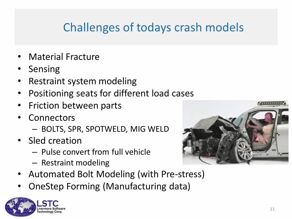
• Material Fracture• Sensing• Restraint system modeling• Positioning seats for different load cases• Friction between parts• Connectors
– BOLTS, SPR, SPOTWELD, MIG WELD
• Sled creation– Pulse convert from full vehicle– Restraint modeling
• Automated Bolt Modeling (with Pre-stress)• OneStep Forming (Manufacturing data)
11
Challenges of todays crash models
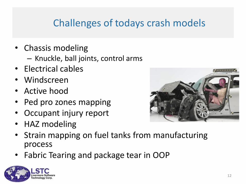
• Chassis modeling– Knuckle, ball joints, control arms
• Electrical cables• Windscreen• Active hood• Ped pro zones mapping• Occupant injury report• HAZ modeling• Strain mapping on fuel tanks from manufacturing
process• Fabric Tearing and package tear in OOP
12
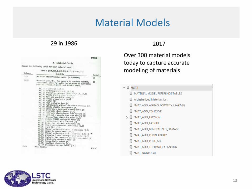
Material Models
29 in 1986
Over 300 material modelstoday to capture accurate modeling of materials
2017
13

LSTC family of Dummies and barriers
ECER95shell
IIHSshell/solid
ODBshell/hybrid
214shell/solid
AE-MDBshellRCAR Barrier RMDB MCB rigid PDB barrier
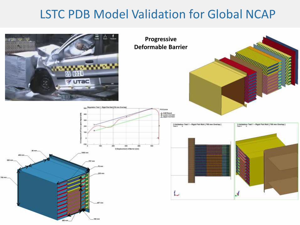
LSTC PDB Model Validation for Global NCAP
Progressive Deformable Barrier
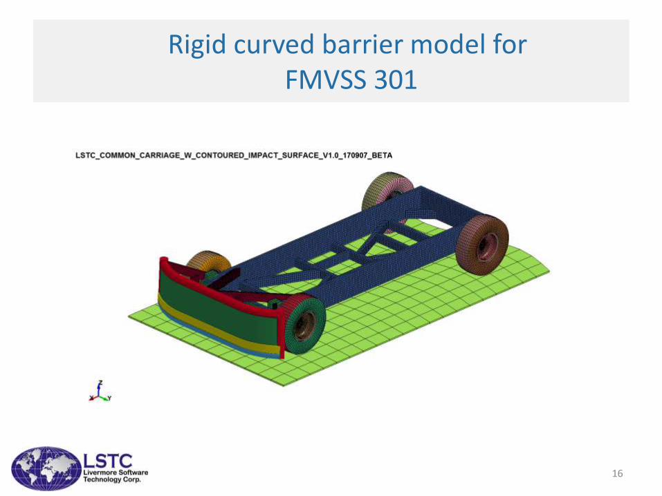
Rigid curved barrier model forFMVSS 301
16
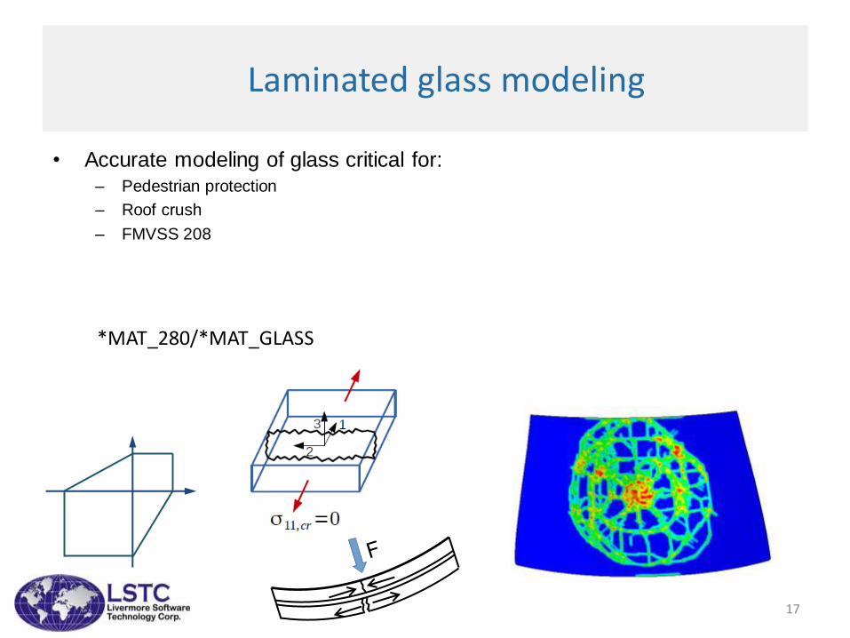
Laminated glass modeling
• Accurate modeling of glass critical for:– Pedestrian protection
– Roof crush
– FMVSS 208
*MAT_280/*MAT_GLASS
17
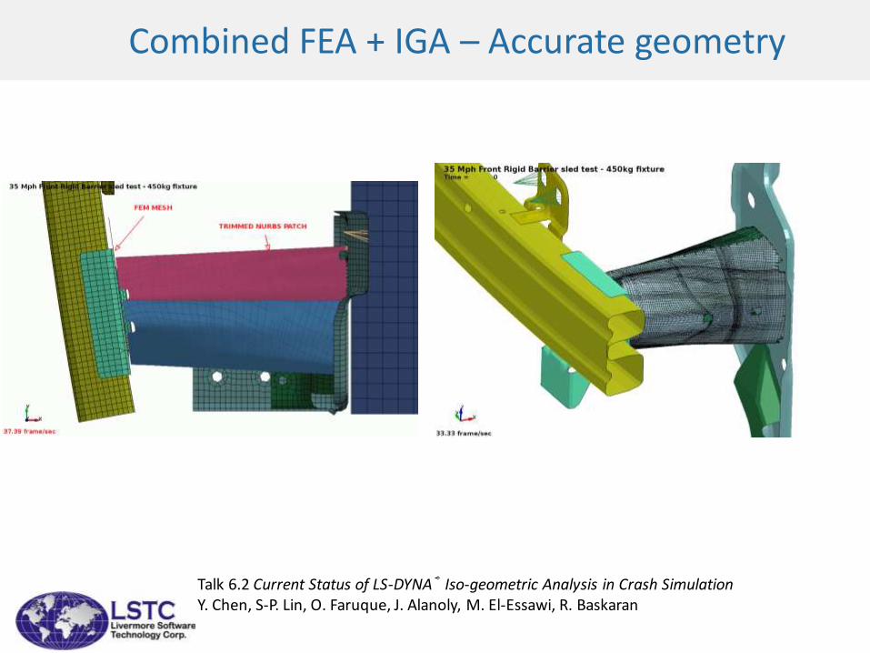
Combined FEA + IGA – Accurate geometry
Talk 6.2 Current Status of LS-DYNA® Iso-geometric Analysis in Crash Simulation Y. Chen, S-P. Lin, O. Faruque, J. Alanoly, M. El-Essawi, R. Baskaran
Accurate airbag modeling
• Driver, passenger, side, curtain, knee....– Airbag folding
– Uniform pressure or CPM method
– Accurate venting methods
• Vent holes
• Porosity
• Adaptive vents
• Pushout vents
19
20
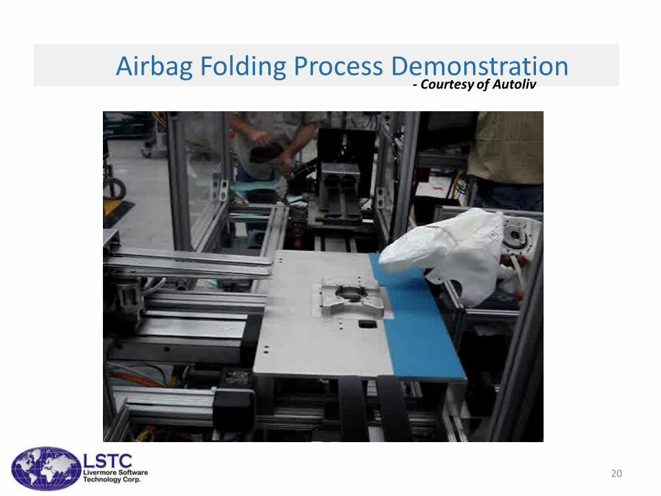
Airbag Folding Process Demonstration- Courtesy of Autoliv
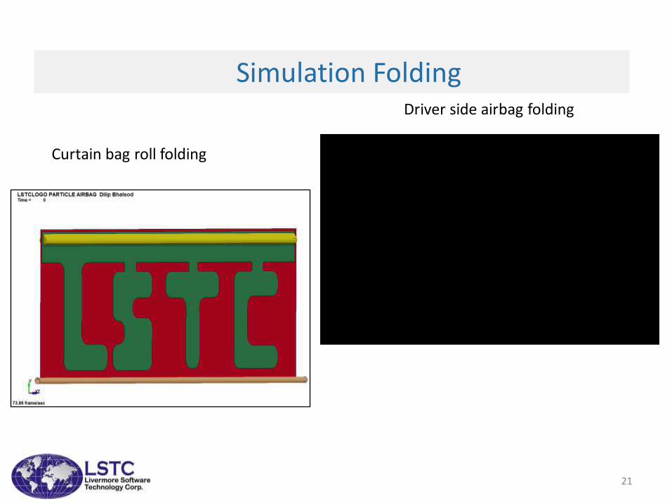
Simulation Folding
21
Curtain bag roll folding
Driver side airbag folding
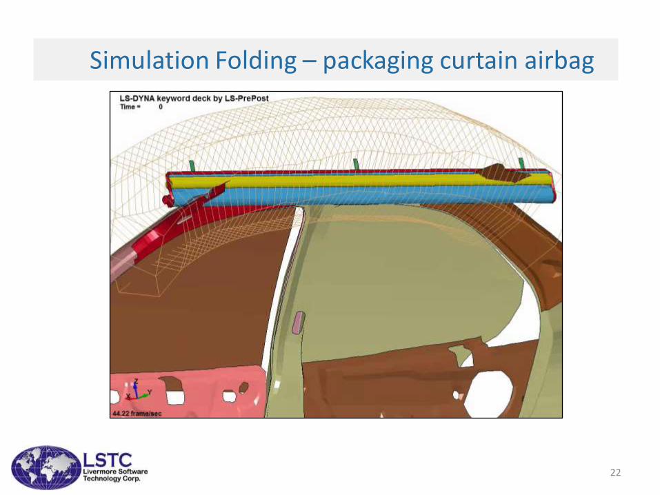
Simulation Folding – packaging curtain airbag
22
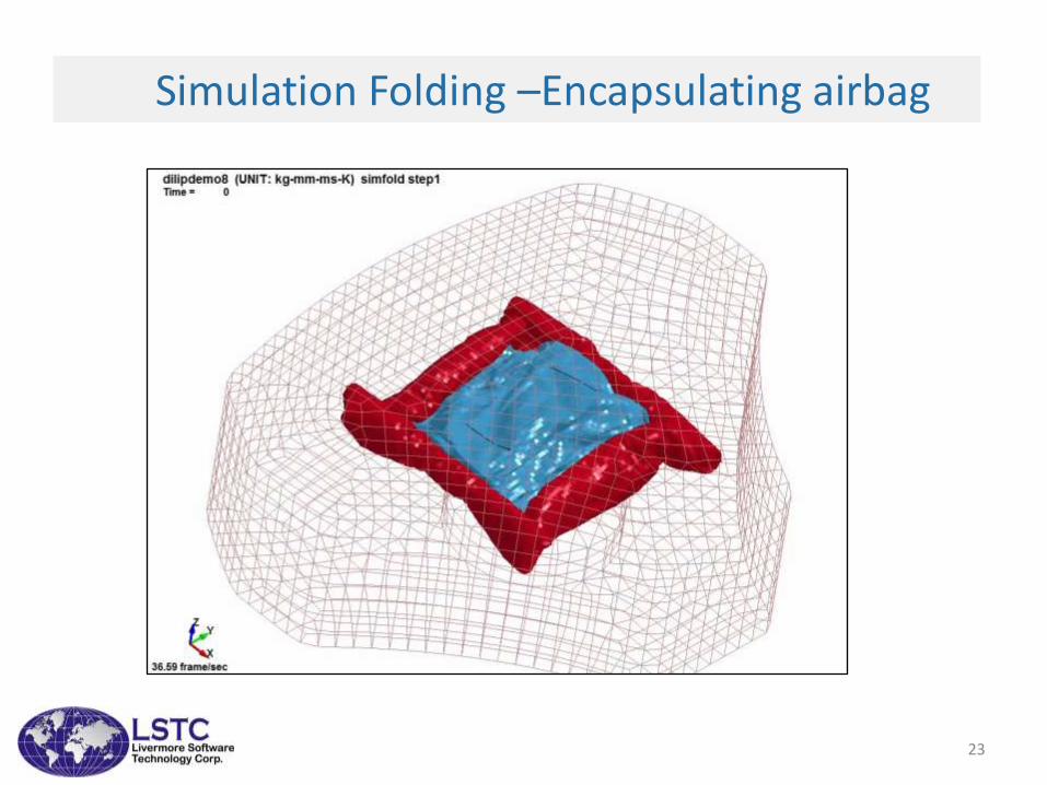
Simulation Folding –Encapsulating airbag
23
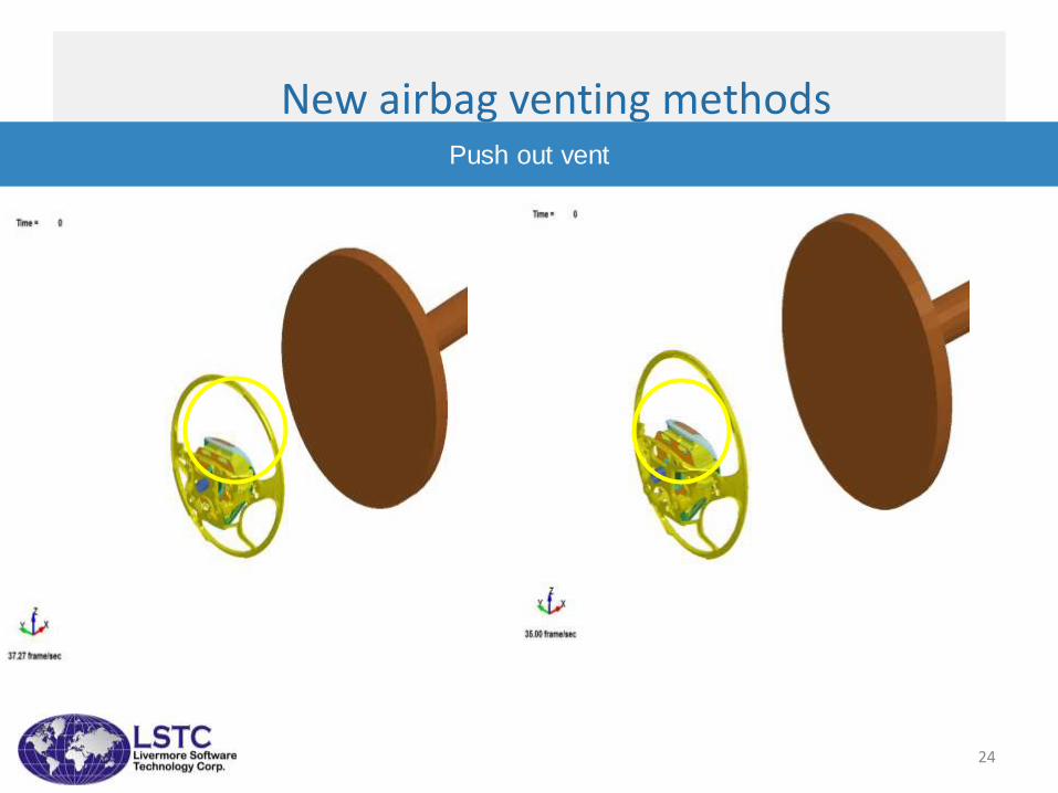
New airbag venting methodsPush out vent
24
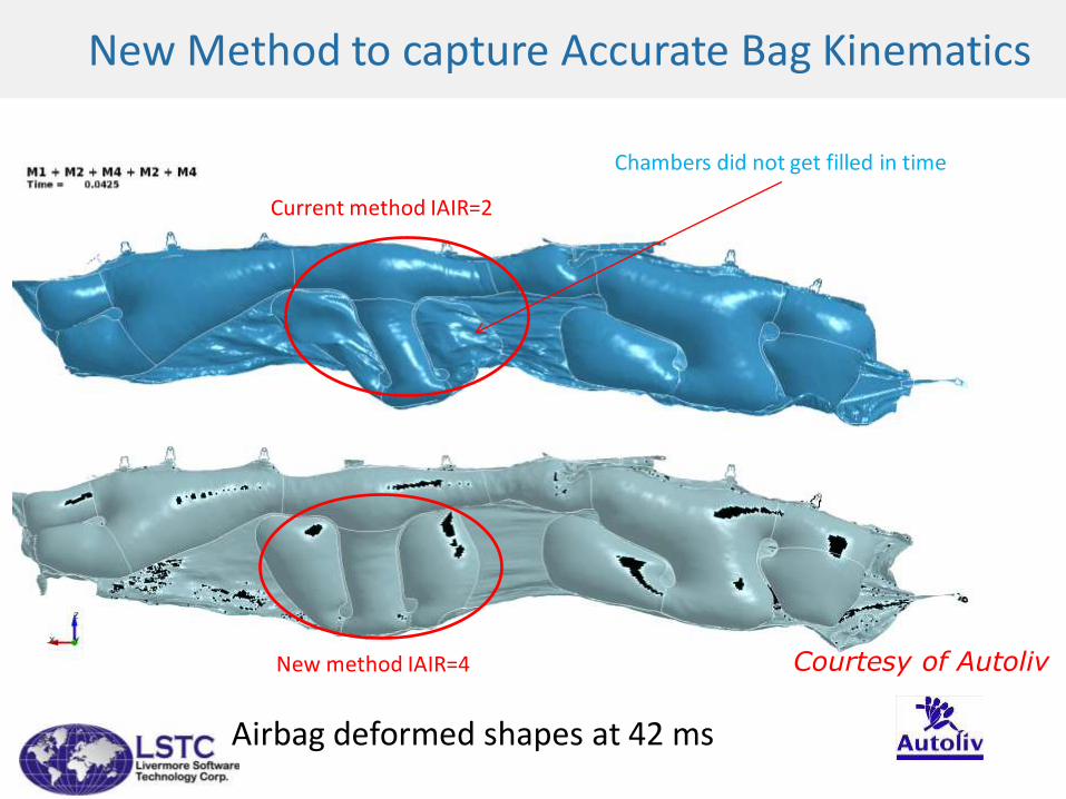
New Method to capture Accurate Bag Kinematics
Current method IAIR=2
New method IAIR=4
Airbag deformed shapes at 42 ms
Courtesy of Autoliv
Chambers did not get filled in time
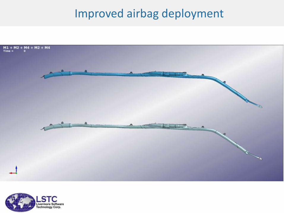
Improved airbag deployment

27
Multi-Physics
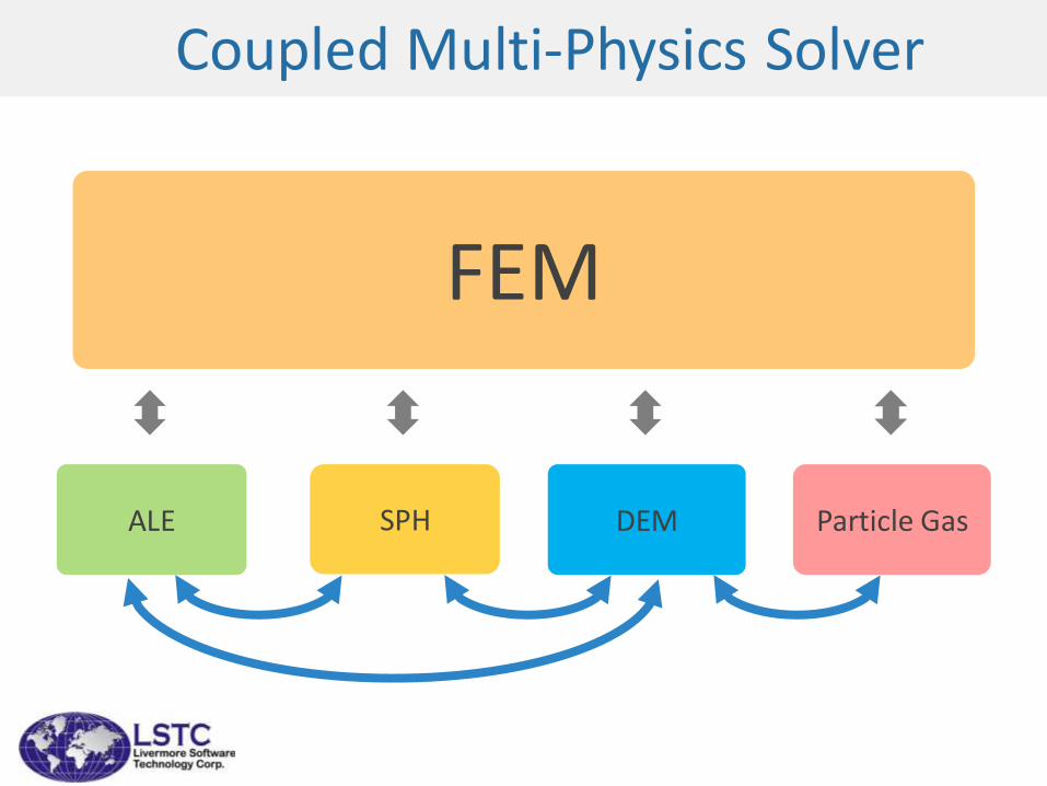
FEM
SPHALE Particle GasDEM
Coupled Multi-Physics Solver
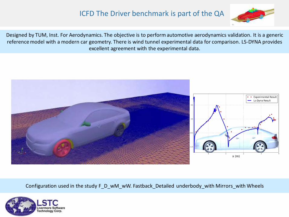
ICFD The Driver benchmark is part of the QA
Designed by TUM, Inst. For Aerodynamics. The objective is to perform automotive aerodynamics validation. It is a generic reference model with a modern car geometry. There is wind tunnel experimental data for comparison. LS-DYNA provides
excellent agreement with the experimental data.
Configuration used in the study F_D_wM_wW. Fastback_Detailed underbody_with Mirrors_with Wheels
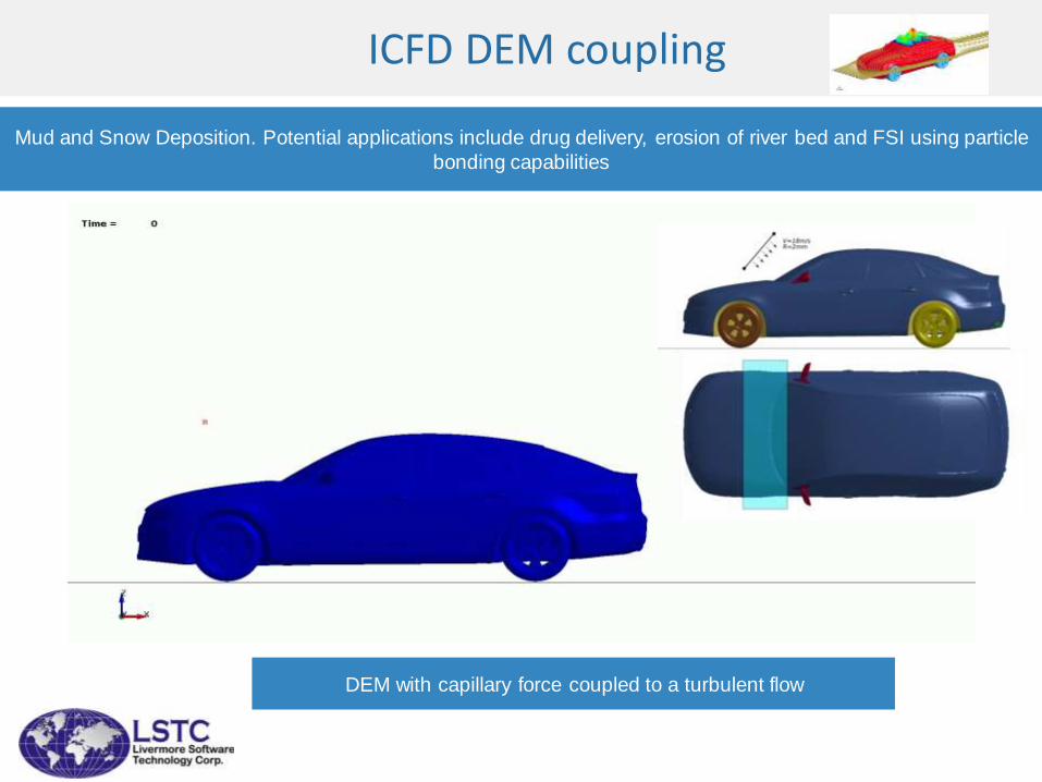
ICFD DEM coupling
Mud and Snow Deposition. Potential applications include drug delivery, erosion of river bed and FSI using particle
bonding capabilities
DEM with capillary force coupled to a turbulent flow
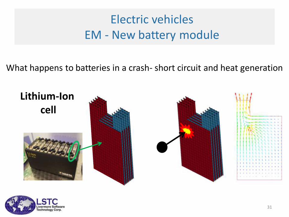
Electric vehiclesEM - New battery module
Lithium-Ioncell
What happens to batteries in a crash- short circuit and heat generation
31
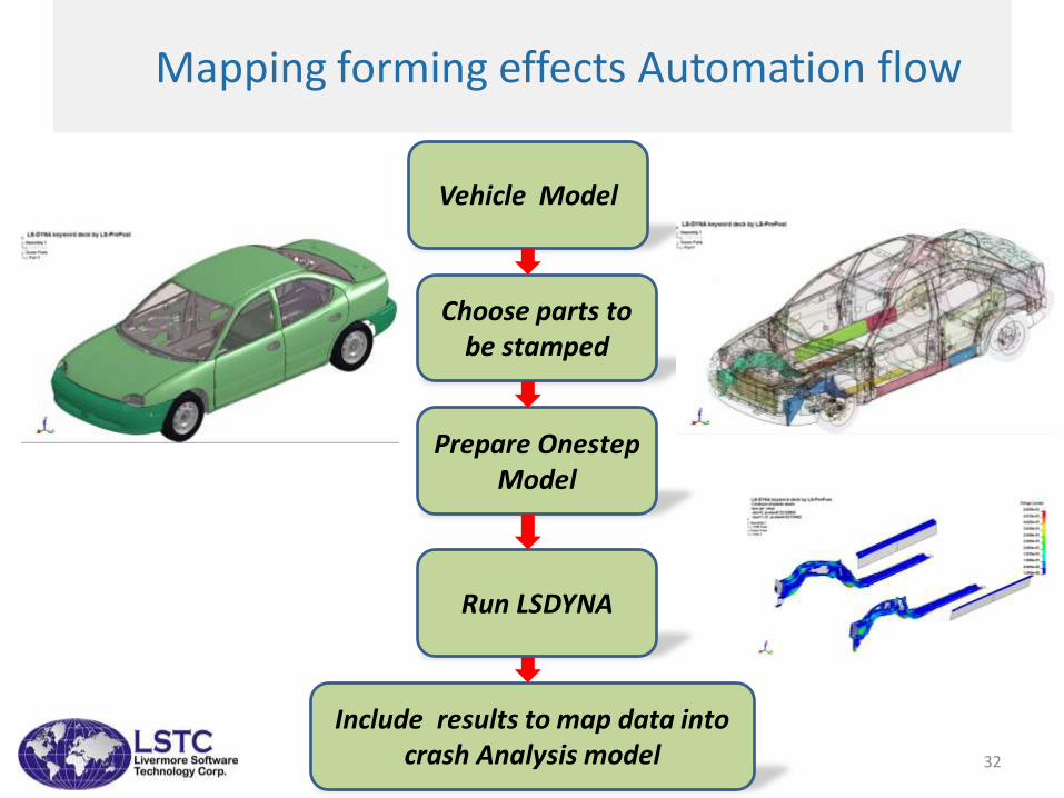
Mapping forming effects Automation flow
Vehicle Model
Choose parts to be stamped
Prepare Onestep Model
Include results to map data into crash Analysis model
Run LSDYNA
32
Crash models
• Automotive companies focus on building
body models and using supplier provided
models like:– Airbag and streering wheel assembly
– Seat models
– Steering column
– Instrument panel
• With this approach subsystems are
validated by suppliers.
33
34
ImplicitLS-OPTLS-TaSC
Human Body Modeling
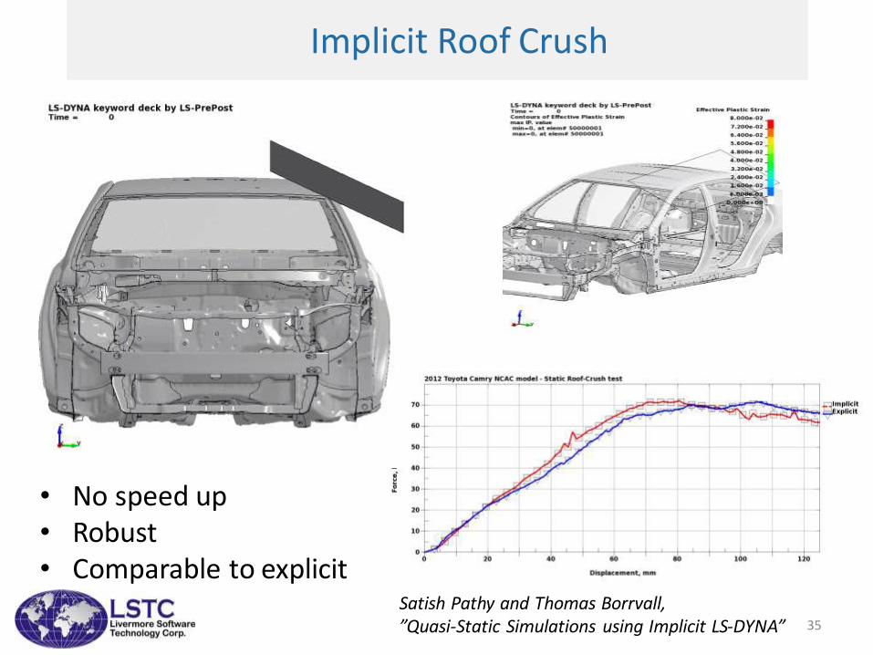
Implicit Roof Crush
• No speed up• Robust• Comparable to explicit
Satish Pathy and Thomas Borrvall,”Quasi-Static Simulations using Implicit LS-DYNA” 35
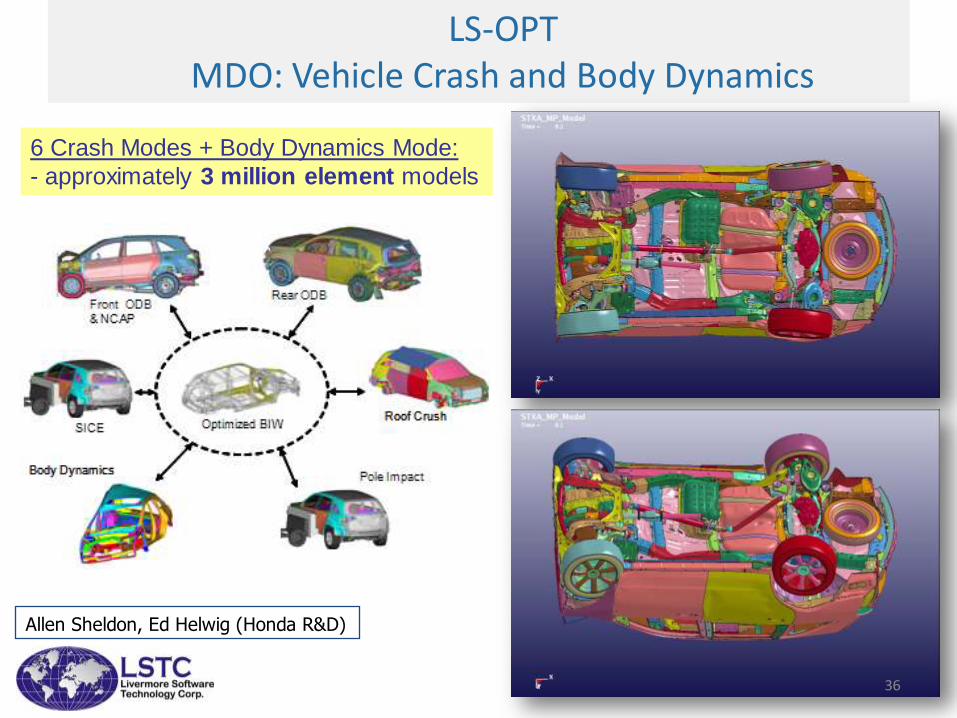
LS-OPT MDO: Vehicle Crash and Body Dynamics
6 Crash Modes + Body Dynamics Mode:
- approximately 3 million element models
Allen Sheldon, Ed Helwig (Honda R&D)
36
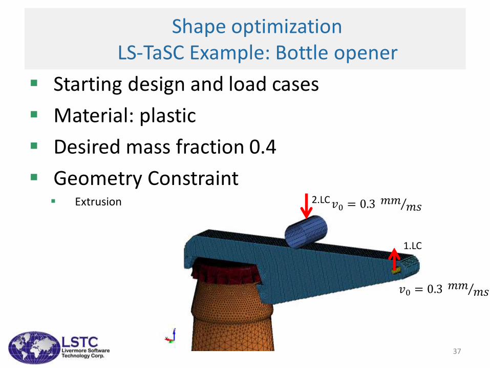
𝑣0 = 0.3 𝑚𝑚𝑚𝑠
1.LC
2.LC𝑣0 = 0.3 𝑚𝑚𝑚𝑠
Shape optimizationLS-TaSC Example: Bottle opener
Starting design and load cases
Material: plastic
Desired mass fraction 0.4
Geometry Constraint Extrusion
37
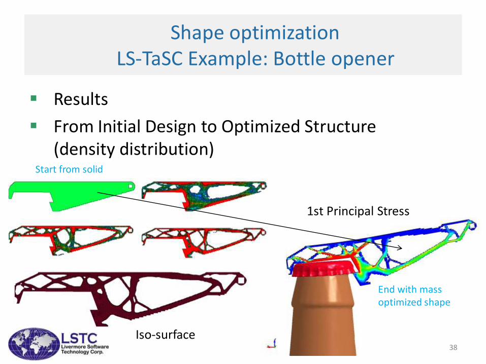
1st Principal Stress
Shape optimizationLS-TaSC Example: Bottle opener
Results
From Initial Design to Optimized Structure (density distribution)
Iso-surface
Start from solid
End with mass optimized shape
38
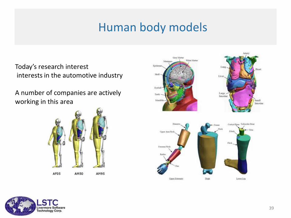
Human body models
Today’s research interestinterests in the automotive industry
A number of companies are activelyworking in this area
39
40