crash safety of hybrid- and battery electric vehicles rainer justen …€¦ · · 2011-04-29benz...
TRANSCRIPT

Justen | 1
CRASH SAFETY OF HYBRID- AND BATTERY ELECTRIC VEHICLES Rainer Justen Prof. Dr. Rodolfo Schöneburg Daimler AG, Mercedes Car Group Germany Paper No 11-0096
ABSTRACT
Besides the suitability for daily use, sufficient cruising range, rapid battery charging times and an area-wide service infrastructure, the crash safety performance will also play a key role for the consumer’ s acceptance of electric vehicles. In particular, the electric energy storages and high voltage systems are very challenging to the crash safety performance.
Already in the Mercedes-Benz S 400 HYBRID in 2009, worldwide the first series-production vehicle with a Lithium-Ion battery, a seven-stage safety concept has been implemented. It has an extremely high performance in terms of functional and operational safety during normal driving and an outstanding crash performance in any real world accidents. Similarly, an intrinsically safe packaging concept has been implemented in all other Mercedes-Benz Hybrid- and Battery Electric Vehicles, such as the ML 450 HYBRID, the A-Class E-Cell, the B-Class F-Cell, and the Smart Electric Drive. All safety relevant components of the high-voltage system have been integrated and protected in a safe manner. This is particularly true for the high voltage battery. The HV-system has been isolated and protected against any contacts, and it will be shut-off in any accident. In the future Mercedes-Benz hybrid- and electric vehicles, this safety concept will be enhanced consistently, by utilizing the Mercedes-Benz safety philosophy of “Real Life Safety”. Its key elements are:
- A foolproof strategy to cut-off the high voltage in accidents will prevent any electric shocks.
- A concept of protection zones defines the accident-proof placement of all the safety relevant high voltage components along with the highest possible structural safety.
- Mechanical requirements for HV-components ensure the electric insulation and shock-proof protection.
- An integrated safety concept shall prevent any critical damages to the high voltage battery in case of high crash loadings.
This paper illustrates Daimler’s concept for crash safety of hybrid- and electric vehicles.
INTRODUCTION
Driven by severe fuel economy and CO2 emission regulations, the automobile industry experiences a fundamental change. Undoubtedly, hybrid and battery electric vehicles will play a major role in the future individual traffic, with the focus on the suitability for daily use, sufficient cruising range, and energy charging time, at reasonable cost. The key to achieve these goals will be the energy storage technology, with Lithium-ion batteries as a future base. Since these new high voltage systems involve some major challenges with regard to functional safety and operating safety, foolproofness and crash safety, an equally important criterion for the acceptance of alternatively driven vehicles by the general public will be the same high safety standards as established for conventional vehicles.

Justen | 2
Some basic requirements to the integrity of the high voltage system, such as the protection against electric shocks and the avoidance of fire or explosion of energy storages after a crash have already been addressed in the existing and currently discussed safety standards for alternative vehicles with high voltage systems (i.e. FMVSS 305, ECE R94/95, GB/T 18384, Attachment 111). This has been the base for the development of the Mercedes-Benz S 400 HYBRID, which has been launched in 2009 as the world wide first series vehicle with a Lithium-ion battery. As a result, the following seven-stage safety concept has been implemented:
1. Color-code and contact protection for all high voltage wiring with amply insulation and special plugs,
2. High-strength steel housing for the lithium-ion battery located well protected in the extremely stiff zone before the fire wall,
3. The battery cells are bedded in a shock absorbing gel, with a separate cooling circuit and a blow-off vent with burst disk,
4. Multiple safety interlock to automatically separate battery terminals,
5. Continuous short circuit and malfunction monitoring,
6. Active discharging of the high voltage system in the event of faults or fire,
7. Pyrotechnical tripping of the voltage system in the event of an accident.
Based on the Mercedes-Benz “Real World Safety” philosophy, this concept will be enhanced consistently in the future Mercedes-Benz hybrid and battery electric vehicles. The key goals will be:
- A high structural safety, based on protection zones for all high voltage components, surrounded by deformation zones to manage the crash energy and specifically programmed to the vehicle concept, while implementing intelligent light weight design.
- An intelligent integration concept for the high voltage battery to prevent critical damages even if directly impacted during a crash.
- The implementing of high requirements to the mechanical stability of all high voltage components, combined with an ultimate shock-proof protection by cut-off and discharge during any accidents.
- The consistent protection of other road users (compatibility) along with an enhanced implementation of the new driver assistance and crash avoidance systems.
Figure 1. Mercedes-Benz hybrid and electric vehicles.
Figure 1 shows an overview of the actual Mercedes-Benz alternative propulsion vehicles. The traction battery of the A-class E-CELL and the Smart Electric Drive is integrated on the floor of the passenger cell. In the F-CELL B-class, the hydrogen tank and the fuel cell stack are located on the floor, while the small HV-battery is well protected on the vehicle’s rear axle. While the mild hybrid battery of the S 400 HYBRID is located behind the right wheel arch, the full hybrid battery of the ML 450 HYBRID is placed on the rear axle. All these integration concepts implement the highest possible crash protection in all accident types.
HIGH VOLTAGE CUTT-OFF IN THE EVENT OF AN ACCIDENT
The power train of both hybrid and electric vehicles utilizes high voltages up to several hundreds of volts, for which severe safety regulations have been

Justen | 3
legislated appropriately. Voltages above 30 V a.c. and 60 V d.c. respectively are in class B voltage, which requires already enhanced protection against electric shock. Nevertheless, the high voltage will be cut-off from the battery and discharged in Mercedes vehicles in any serious accidents, in order to reliably avoid any risks of electrical shocks even at very high vehicle damages [1]. By opening the battery contactors, the high voltage must be reduced below 60 V d.c. and 30 V a.c. accordingly in less than 5 seconds. High voltage sub-systems with extremely high energies in the link will be discharged actively by a short circuit. Generally, this HV-deactivation is linked to the crash detection sensors for frontal / lateral / rear crash and rollover, and the subsequent activation of the restraint system. Two different switch-off strategies have been implemented (Figure 2):
Figure 2. High-voltage cut-off in a crash.
1. In minor severe accidents, i.e. frontal collisions with activation of the seat belt pretensioners or the 1st stage of airbags, the high-voltage system will be shut-down reversibly. After the self diagnosis has not detected any insulation faults, the HV-system will be re-activated, and the engine of vehicles still drivable can be re-started.
2. In any severe accidents (i.e. airbags fully fired in frontal crash), the HV-system will be cut-off irreversibly. In this case, a re-start of the engine will only be possible after a diagnosis or repair has been conducted at an authorized service station.
CRASH PROTECTION ZONES FOR HV-COMPONENTS
Extremely important for the safety performance of battery electric and hybrid vehicles in any real world accidents is the well protected placement of all safety relevant components. This is particularly true for the high voltage battery which must not be damaged even in very severe accidents resulting in any crucial cell damages or a loss of protection against contact. In order to define the protection zones for the best possible integration of energy storages, a specific study was conducted [2] by analyzing the damages of approx. 9000 vehicles involved in severe real world accidents, using the German In-Depth Accident Study (GIDAS) data base [3]. For each vehicle, the deformations in the lower vehicle (floor) level were plotted in a standardized 2-D grid. By consolidating the resulting deformation matrix with the accident frequency and severity, the probability of the deformation of each vehicle cell in any crash type can be evaluated accordingly. Figure 3 compares the resulting deformation matrix of a station wagon with the vehicle intrusions in the standard crash tests.
Figure 3. Comparison of vehicle intrusions in real world accidents and crash tests.
Based on this deformation probability matrix, three deformation zones have been specified for the safe location of high voltage components (Figure 4):

Justen | 4
Figure 4. High voltage safety protection zone concept.
Protection Zone 1: The outside deformation area which is already damaged in minor collisions without any activation of the restraint system is a keep-off zone for any HV-components. If (for whatever reason) the location of a HV component in this area were unavoidable, it must be well protected against any damages in minor or serious accidents, and the high voltage wiring must be coated additionally.
Protection Zone 2: Areas deformed in medium severe frontal collisions characterized by firing the belt pretensioner or the 1st stage of the airbag require enhanced protection against contact according to class IPXXB with a test finger of a diameter of 12 mm (Figure 5).
Figure 5. Contact protection of HV-components
Protection Zone 3: The preferred zones for the location of high voltage systems are not damaged in the standard crash tests, and only with a probability of less than 2 % in real world accidents. Areas deformed in the standard crash tests should be avoided.
THE CRASH SAFETY OF HIGH VOLTAGE BATTERIES
The current safety standards of high voltage batteries address the chemical and thermal performance of battery cells during mechanical loads, i.e. pressure forces and intrusion. Due to the high loads, the cells will be damaged typically, with the result of electrolyte leakage. Undisputed the fact that these cell tests are crucial for the design of HV-batteries, they do not represent the typical loads to the battery during crash or even in severe real world accidents [4, 5, 6]:
- Crash simulations indicate that the maximum loads applied to the battery rarely exceed 200 kN. The key reason for this phenomenon are the indirect, multiple and distributed load paths of the crash propagation: i.e. the battery protecting cage and the surrounding vehicle structure may absorb energy, the battery may move and dodge, the battery mounting and housing may be deformable, and other compliances and reinforcements may cushion the peak loads to the battery.
- The forces specified in the current battery standards (i.e. SAE J2464), i.e. the thousand fold of the battery weight is not high enough to achieve the 50 % battery crush (of the battery dimension) targeted; even the small 20 kg battery of a mild hybrid vehicle battery will be crushed only by approx 11 % with a static load of 200 kN.
- Another crucial difference of crash loads versus quasi-static tests is the time scale: due to the very short period of the whole crush of approx 100 ms (the blink of the eye) peak loads are applied only for milliseconds. Same as any component, the battery withstands much higher short-period dynamical forces than the maximum static loads.
Justen | 5
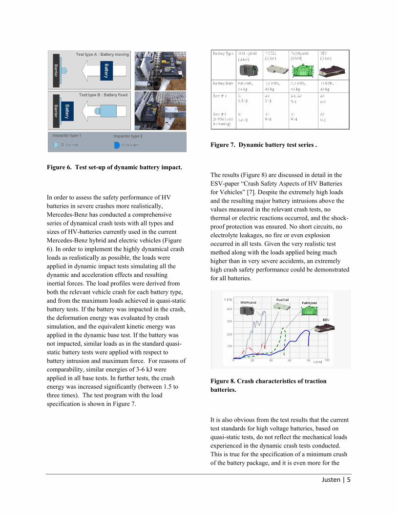
Figure 6. Test set-up of dynamic battery impact.
In order to assess the safety performance of HV batteries in severe crashes more realistically, Mercedes-Benz has conducted a comprehensive series of dynamical crash tests with all types and sizes of HV-batteries currently used in the current Mercedes-Benz hybrid and electric vehicles (Figure 6). In order to implement the highly dynamical crash loads as realistically as possible, the loads were applied in dynamic impact tests simulating all the dynamic and acceleration effects and resulting inertial forces. The load profiles were derived from both the relevant vehicle crash for each battery type, and from the maximum loads achieved in quasi-static battery tests. If the battery was impacted in the crash, the deformation energy was evaluated by crash simulation, and the equivalent kinetic energy was applied in the dynamic base test. If the battery was not impacted, similar loads as in the standard quasi-static battery tests were applied with respect to battery intrusion and maximum force. For reasons of comparability, similar energies of 3-6 kJ were applied in all base tests. In further tests, the crash energy was increased significantly (between 1.5 to three times). The test program with the load specification is shown in Figure 7.
Figure 7. Dynamic battery test series .
The results (Figure 8) are discussed in detail in the ESV-paper “Crash Safety Aspects of HV Batteries for Vehicles” [7]. Despite the extremely high loads and the resulting major battery intrusions above the values measured in the relevant crash tests, no thermal or electric reactions occurred, and the shock-proof protection was ensured. No short circuits, no electrolyte leakages, no fire or even explosion occurred in all tests. Given the very realistic test method along with the loads applied being much higher than in very severe accidents, an extremely high crash safety performance could be demonstrated for all batteries.
Figure 8. Crash characteristics of traction batteries.
It is also obvious from the test results that the current test standards for high voltage batteries, based on quasi-static tests, do not reflect the mechanical loads experienced in the dynamic crash tests conducted. This is true for the specification of a minimum crush of the battery package, and it is even more for the

Justen | 6
correlation of the maximum load to the battery weight. As a result, these standards must be modified appropriately.
INTEGRATED SAFETY CONCEPT FOR HV-BATTERIES
Although it must be the ultimate goal to locate the HV-battery in a well protected zone as described above, this will not always be feasible in all vehicles, and under all circumstances. This is particularly true in small electric vehicles with traction batteries of the dimension of approx 1200 x 500 x 200 mm, or if more than one battery will be needed to achieve a satisfactory cruising range. On the other hand, the dynamic crash tests described above have proven that HV-batteries can withstand very high crash impacts without any severe damages. And severe crash tests with different vehicle sizes, different battery types and sizes, different battery integration concepts and locations have shown that an equally high crash safety performance can be achieved by implementing an intelligent safety integration concept which takes into account the following relevant criteria:
- The safety performance of the battery materials, the chemistry of the cells in particular, i.e. the electrolyte and material of the anode and cathode.
- The battery stability, in particular the enclosure material, interior expansion space and deformation zones, appropriate arrangement of the connectors of the electronics and of the cooling ports.
- The battery protection, i.e. a stiff cage around the battery, reinforcements in the surrounding vehicle structure.
- The battery integration, such as a programmed compliance in the mounting, clearances for battery movement, no block building, staggered arrays.
- The safety performance of the battery in the crash tests, i.e. battery impact, maximum crash loads, battery intrusion or damage.
- The ultimate mechanical loads to the battery in the static and dynamic battery tests, i.e. enclosure cracks, electrolyte leakages, short circuits, fire explosion.
CONCEPT OF STRUCTURAL INTEGRITY AND CRASH COMPATIBILITY
Due to the changes in the power train and energy storages, the packaging of the traction battery in particular, alternatively driven vehicles are exposed to major challenges in the crash performance such as the stability of the vehicle structure and the related occupant protection. This is particularly true for the compatibility in a collision with other road users such as a (smaller / bigger) car, a cyclist or pedestrian. In addition to the compatibility features of conventional vehicles, the mass ratio, the structural stiffness ratio and the geometric suitability, some additional challenges have to be addressed. One specific focus is on the avoidance of collisions with pedestrians and cyclists due to the missing engine noise of electric drives, where even a new regulation is under discussion. Another aspect is the hazard to 3rd parties, rescue people in particular, due to damages of the high voltage system in an accident, and the potentially resulting electric shock, electrolyte leakage, vehicle fire or even explosion. As a result, the enhanced implementation of the new crash avoidance technologies will play a major role in improving the safety performance of alternative vehicles.
In the actual vehicle population, a maximum mass ratio of 1:2, and the resulting inverse ratio for the velocity change of the two vehicles in the collision, can be managed in today’s advanced occupant protection system. With future alternative vehicles in the exposure, this ratio may potentially increase up to 4:1 since on the one hand, the weight of small electric vehicles must be reduced significantly in order to increase their cruising range. Oh the other hand, the weight of hybrid cars such as big limousines or SUV will increase due to the additional traction battery and electric drive. The management of the resulting delta V’s in car-to-car collisions through the restraint

Justen | 7
system, in order to achieve tolerable occupant loadings, will be a major challenge.
With regard to the structural and geometrical compatibility of hybrid and electric vehicles, a particularly important aspect will be the well protected integration of the high voltage systems in vehicle areas which will not be damaged in any severe accidents. Another focus is the energy absorbing crush zones which must be programmed specifically to the packaging concept of the vehicle’s key components. Table 1 shows the impact of the different alternative vehicle concept on the crash performance.
Table 1. Impact of alternative propulsion concepts on
crash performance
* Compared to conventional vehicle
The elimination of the conventional combustion engine in battery electric vehicles will enable new crush zones in the vehicle front. On the other hand, the integration of the relatively big and sensitive traction battery will require very stiff areas which must not be deformed in a crash in order to protect the battery. An obvious area for the battery is the vehicle floor, thus killing two birds with one stone: Since the passenger cell must be designed extremely stiff for the occupant protection in order to prevent any major intrusions (“safety cage”), a stiff vehicle floor along with very solid rocker panels will also enable a very high protection of the battery from any damages in severe crashes. In electric vehicles with a small combustion engine as a range extender must take into account the packaging of the engine and the fuel tank in the vehicle rear. Accordingly, the stack and the hydrogen tank of fuel cell vehicles will be placed on the vehicle floor, while the relatively small
high voltage battery as an energy buffer will be located well protected above the rear axle.
The BlueZERO concept for the future alternatively driven Mercedes vehicle generations will be based on a flexible modular safety packaging concept, as shown in Figure 9. The sandwich floor already realized in the A- and B-class will house the different energy storages as needed, and the space above the rear axle may be used for any additional components which must be protected in vehicle crashes. As a result, all variants of battery electric vehicles, even a gas fueled engine fueled can be implemented on this platform.
Figure 9. Concept BlueZERO.
OPPORTUNITIES FOR ENHANCED CRASH AND OCCUPANT PROTECTION IN HYBRID AND ELECTRIC VEHICLES
A major roadblock for the consumer acceptance of electric vehicles is their still very limited cruising range. As a result, by utilizing the formula “Less Weight = Less Energy Consumption = Smaller Traction Battery = Lower Vehicle Cost”, consistent light weight design will be a key to the success of

Justen | 8
electric vehicles in the market. Due to the high cost of HV batteries (i.e. 1000 € for a 100 kg battery), an additional 10-15 € could be spent for each kg vehicle weight reduction without a significant increase of the vehicle cost [8]. This may push a break-through of light-weight design in electric vehicles, enabling new materials and technologies which have been too expensive for conventional vehicles, even exotic carbon fibers (Figure 10).
Figure 10. Vehicle body with carbon elements.
Since the traction battery may amount for up to 20 % of the total vehicle weight, a specific focus should be on weight reduction measures, such as utilizing the vehicle floor itself to house the battery.
Given the partially more difficult crash performance of alternative vehicles, another important aspect to enhance the safety performance will be the consistent implementation of the new crash avoidance and driver assistance systems. This is particularly true for the Mercedes-Benz PRE-SAFE systems which can be significantly improved by utilizing the high electric power available from the high voltage batteries. One
example is the motorized seat belt which, with the current 12 V power supply, is limited in both the pretension times of minimum 100 ms, and the belt-to-occupant retraction force of maximum 200 N. With the power of 400 V, this performance data could be easily increased to less than 10 ms and up to 800 N. This would not only allow to use motorized seat belts also in the event of a crash and thus to eliminate the pyrotechnical seat belt pretensioners, but also to pull an occupant “out- of-position” back into the seat backrest. This would be a major benefit in many real world accidents where the occupants are no longer in the ideal back position due to a forward movement by emergency braking, vehicle spinning or minor impacts preceding the most severe crash.
REFERENCES
[1] Justen Rainer, Schöneburg Rodolfo Prof., Unfallsicherheit von Hybrid- und Elektrofahrzeugen, VDA-Technischer Kongress 2011, Ludwigsburg, 24.3.2011. [2] Joerg Bakker, Rainer Justen, Daimler AG; Christian Sachs, Flavio Friesen, Adam Opel AG - General Motors Company; Dietmar Otte, Medical University Hannover; Lars Hannawald, VUFO GmbH, Analysis of Fuel Cell Vehicles Equipped with Compressed Hydrogen Storage Systems from a Road Accident Safety Perspective, SAE 11B-0132 / 2011-01-0545. [3] GIDAS Project, “German In-Depth Accident Study”, http://www.gidas.org/en, 2010. [4] Justen Rainer, Schöneburg Rodolfo Prof., Schröter Dirk Dr, Kaufmann Rainer Dr,, Crashsicherheit von Lithium-Ionen-Batterien für Hybridfahrzeuge; Crash.tech 2010, Leipzig, 14.4.2010. [5] Lamm Arnold Dr., Justen Rainer, u.a. Daimler AG; Safety Aspects on Li-Ion Batteries for Future Mobility Concepts; 12. UECT 2010, Ulm, 17.6.2010.

Justen | 9
[6] Justen Rainer, Schöneburg Rodolfo Prof., Dieter Scheunert, Arnold Lamm Dr, FIVE – Fires in Vehicles, Conference Gothenburg, Sweden, 30.9.2010. [7] Wech Lothar Dr. Richter Richard, TÜV-Süd Automotive GmbH, Germany, Justen Rainer, Schöneburg Rodolfo Prof., Daimler AG, Germany, Crash Safety Aspects of HV Batteries for Vehicles, 22th Enhanced Safety Vehicles Conference, Washington, USA, June 13th – 16th. [8] Eckstein Lutz Prof. u.a., Leichtbau bei Elektrofahrzeugen, ATZ Automobiltechnische Zeitschrift, Germany, 11/2010.