creating distraction at the knee joint: a treatment option
TRANSCRIPT

1
Creating distraction at the knee joint:
a treatment option for osteoarthritis
Final Report December 14, 2011
Team Members Kelsi Bjorklund (Team Leader)
Jacob Stangl (BSAC) Taylor Lamberty (Co-BWIG)
Amy Martin (Communicator) Lindy Couwenhoven (Co-BWIG)
Client Kim Skinner, M.P.T., C.S.C.S.
Advisor Tracy Puccinelli, Ph.D.

2
Table of Contents
Abstract 4
Background 5
Client Description 5
Current Devices 5
Marketed Devices 5
Problem Motivation 7
Design Requirements 8
Prior Work 9
Design Alternatives 10
Free Weight Design 10
Band Design 11
Pump Design 12
Design Matrix 13
Effectiveness 14
Patient Comfort 14
Safety 15
Durability 15
Cost 16
Portability 16
Testing and Results 16
Testing 16
Discussion 17
Future Work 19
Cost 20
Timeline 21
References 22

3
Appendix 23

4
Abstract
Our client, Kim Skinner, is a practicing physical therapist at Group Health Cooperative of South
Central Wisconsin. She treats many patients who suffer from knee osteoarthritis and also suffers
from symptoms herself. It is a painful and degenerative disease that is caused by the
deterioration of the articulate cartilage in the knee, causing a narrowed joint space [1]. Recent
studies have shown that joint distraction (the forced separation of the two bony ends of a joint)
increases cartilage thickness, decreases denuded bone area, decreases pain, and improves
functional ability [1]. Mrs. Skinner has asked our group to create an at-home system for joint
distraction on the knee in hopes of prolonging, or even eliminating, the need for knee
replacement surgery. Our team has designed a device which utilizes the natural force of gravity,
as well as an air pump system to distract the knee joint, relieving pressure and stress on the joint.
Initial testing of this device has proven successful in applying a distraction force significant
enough to separate the joints in the knee. With further work, we are hopeful that this product will
be made available to all those who suffer from knee osteoarthritis.
5
Background
Client Description
Kim Skinner is a physical therapist at Group Health Cooperative in Madison. She works with a
variety of patients who require physical therapy for a multitude of reasons, but over the years has
noticed the prevalence of knee osteoarthritis. Kim would like our group to design a portable
knee traction unit for home use to help slow the progression of knee osteoarthritis in her patients.
Her clinic currently provides portable cervical and lumbar traction devices, and she would like to
offer a similar option for clients that suffer from knee osteoarthritis. By using a knee traction
device regularly, it is hopeful that patients will be able to slow the progression of their
osteoarthritis, further eliminating the need for knee replacement surgery or other invasive
treatments [1].
Current Devices
Marketed Devices
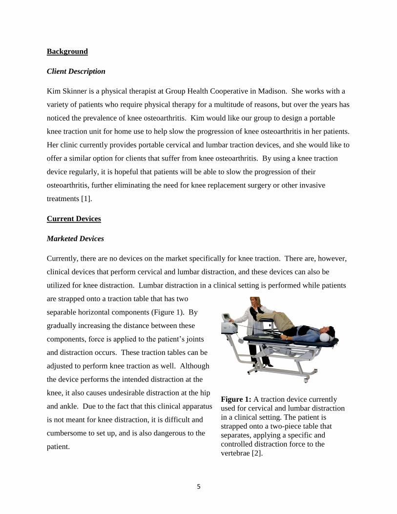
Currently, there are no devices on the market specifically for knee traction. There are, however,
clinical devices that perform cervical and lumbar distraction, and these devices can also be
utilized for knee distraction. Lumbar distraction in a clinical setting is performed while patients
are strapped onto a traction table that has two
separable horizontal components (Figure 1). By
gradually increasing the distance between these
components, force is applied to the patient’s joints
and distraction occurs. These traction tables can be
adjusted to perform knee traction as well. Although
the device performs the intended distraction at the
knee, it also causes undesirable distraction at the hip
and ankle. Due to the fact that this clinical apparatus
is not meant for knee distraction, it is difficult and
cumbersome to set up, and is also dangerous to the
patient.
Figure 1: A traction device currently
used for cervical and lumbar distraction
in a clinical setting. The patient is
strapped onto a two-piece table that
separates, applying a specific and
controlled distraction force to the
vertebrae [2].

6
In addition to clinical practices, the client occasionally performs her own at-home method of
knee distraction using ankle weights. While wearing the weights, she positions herself on a
staircase and hangs her leg over the stairs. Gravity pulls the knee apart, providing the desired
knee distraction. However, the dilemma with this method is that the ankle weights are not heavy
enough and therefore do not apply enough force to create significant and long-term results.
In addition to the previously stated clinical devices,
portable cervical and lumbar units for at-home
treatment exist in a variety of different forms. The
Saunders Cervical Neck Traction Device is a twelve
pound portable unit that can apply up to 50 pounds
of force to distract the vertebrae in the neck (Figure
2) [3]. The Saunders Lumbar Traction Unit uses a
similar principle to distract the lumbar region of the
back (Figure 3) [4]. There are also different
variations of these models available to encompass a
wide range of osteoarthritis severities.
Although neither of these units can be used to
distract the knee, several aspects of their design
can be applied to a portable knee traction device.
Both the cervical and lumbar units are light
weight and easily portable, making it convenient
for the patient to use on a regular basis.
Additionally, both of these devices utilize a
hand-held pump with a pressure release valve,
which enables the user to have constant control of the force exerted by the device [4]. Ideally,
this hand-held pump mechanism could be incorporated into a portable knee traction unit.
Figure 3: The Saunders Lumbar Traction
Unit functions similarly to the cervical
traction device. Both the cervical and
lumbar units utilize a hand held pump with
a gauge and lock-release mechanism to
provide and maintain the distraction force
[4].
Figure 2: The Saunders Cervical
Neck Traction Device is currently
available on the market for
patients to provide at home
distraction therapy similar to what
they might experience in a clinical
setting [3].

7
Problem Motivation
Osteoarthritis (OA) is a painful, degenerative disease that affects millions of people around the
world. Often referred to as “wear-and-tear” arthritis, OA is the breaking down of the cartilage
that cushions the joints, which causes the bones to rub together and leads to subsequent pain [5].
Joint distraction is a procedure that gradually separates the two bony ends of a joint for a
specified amount of time [1] [8]. Recent studies have shown that distraction of joints allows the
cartilage between the joints to grow back and thicken [1]. Invasive arthroscopic surgical
procedures have been performed, supplying a distraction to the knee. These experiments have
shown to be effective in delaying the, often requisite, total knee replacement surgery as this
procedure promotes cartilage re-growth [9]. However, a surgical procedure is required and a
device implanted in the body must be worn for a period of eight to 12 weeks, limiting the
patient’s lifestyle and comfort [9]. Therefore, a noninvasive device that replicates this treatment
for knee osteoarthritis without the need for surgery is preferred [10]. As previously mentioned,
cervical and lumbar traction units are currently available on the market; however, a traction unit
for the knee has not yet been produced. The goal of this design project is to provide a non-
Figure 4: A comparison of a healthy knee and a knee with osteoarthritis. The left picture shows
an x-ray image and the right illustrates a diagram of the progression of osteoarthritis [6]. The
cartilage cushioning is clearly present in a healthy knee, while there is a lack of cartilage
between the bones in an osteoarthritic knee [7].

8
surgical device that can be used as a home-based treatment method by creating distraction in the
knee. When used regularly, the effects of osteoarthritis could be diminished and potentially
reversed. A device to distract the knee would be greatly advantageous for patients by prolonging
the life of their knee and either delaying, or completely eliminating, the need for total knee
replacement surgery [11].
Design Requirements
The design requirements outlined in the Product Design Specifications in the Appendix are
explained in detail here. Requirements for this design revolve around three main focuses: safety
requirements, client requirements, and patient comfort.
Safety requirements are crucial to the design process and must be met in order for the device to
be usable and effective. The knee distraction device must not cause pain or further damage to
any part of the body. Therefore, it must not distract either the hip or the ankle joints. The device
must also meet all the requirements for class one medical devices established by the FDA.
In addition to the safety requirements, the design must also meet the requirements set forth by
the client. The client has specified that the distraction force should be constant, and not vary
over the time it is used. It is estimated that the applied force should be about half of the weight
of the leg, with a maximum force of 311.4 N (70 pounds). Increments of force should be
available, and total force should range from zero to 311.4 N. The client would also like the
product to be portable so that patients are able to use it in their homes between doctor visits.
Furthermore, the knee will have to be positioned in a 30° angle from the horizontal, often
referred to as the “open pack” position. This angle of the knee allows for the most separation
between the bony ends of the tibia and femur. Due to the wide variety of body types and sizes,
all components of the device will need to be adjustable, especially the strap that fastens around
the upper calf. Additionally, since the patient will be using it at home without the aid of a
physical therapist, usability is important. The device will need to be user-friendly so that people
with knee osteoarthritis are able to operate it with ease and without causing further pain to their
affected joints. The device should have the durability to last a lifetime because the patient will
use it two to three times a day in 15-20 minute increments [12]. These requirements that have

9
been set forth by the client will play a significant role in the final design of the knee traction
device.
Finally, patient comfort is very important to consider when designing the device. All of the
components of the device in contact with the skin need to be non-abrasive and adjustable so that
the patient feels relaxed and comfortable while using it. The materials used should also be easily
sanitized and cleaned. The knee and leg should be supported, while assuring that all other parts
of the body are not restricted. A wide range of components go into the design requirements
including safety requirements, client requirements, and patient comfort. All are important to the
success of our design, and all are taken into account when developing and deciding design
options.
Prior Work
Free Body Diagram
Figure 5: A free body diagram of the lower leg and our device. FC is the tensile force from
ligaments in the knee. FM is the tensile force of the quadriceps muscle. FJ is the joint force. FD is
the distraction force from the device. W is the weight force of the lower leg. N is the normal
force exerted on the leg from the device.
For our calculations, we modeled FC, FJ, FM as zero, as we want to minimize these forces in
order to have optimal distraction between the joints. We can model FM as zero because the
quadriceps muscle will be relaxed, and therefore, will not be applying any force to the knee. FJ
can be modeled as zero because if distraction is being performed, the joints will not be touching
and will not supply a force against each other. The tensile force from ligaments (FC) can never
30°
FJ
N
W
FD
FC
FM
10
truly be zero, but we will model it as such because when the knee is in the “open-pack” position,
the tensile force is minimized. We modeled FD as 70 pounds (311.4 N) because it is the
maximum traction force that our device will supply. Variable “W” depends on the weight of the
individual. By equating the forces in the horizontal and vertical directions, all unknown forces
were found. These equations were:
= -FDsin30 + Nsin60 – W = 0 (1)
Ʃ X = FDcos30 + Ncos60 = 0 (2)
By evaluating equations 1 and 2 all unknowns were found and incorporated into fabrication of
the design. [13][14][15].
Design Alternatives
Prior to building and testing, three design alternatives were conceptualized and evaluated based
on criteria set in the design matrix shown below (See Table 1). All designs were created for the
patient to be seated in a standard kitchen chair, 0.4826 m (19 inches) tall, and will keep the knee
at a 30° angle from the horizontal in order to maintain an “open pack” position. All three
designs will maintain this 30° angle through the incorporation of a triangular structure
underneath the leg. This will function to support the leg, as well as keep the quadriceps and
hamstring muscles relaxed so that no unnecessary tension forces act upon the knee. No support
will be given to the foot and it will be suspended with the heel resting on the top of the device.
An additional component utilized by all three designs is a strap around the leg directly below the
knee.
Free Weight Design
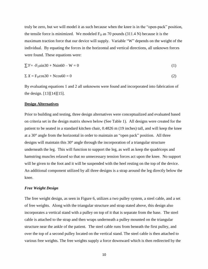
The free weight design, as seen in Figure 6, utilizes a two pulley system, a steel cable, and a set
of free weights. Along with the triangular structure and strap stated above, this design also
incorporates a vertical stand with a pulley on top of it that is separate from the base. The steel
cable is attached to the strap and then wraps underneath a pulley mounted on the triangular
structure near the ankle of the patient. The steel cable runs from beneath the first pulley, and
over the top of a second pulley located on the vertical stand. The steel cable is then attached to
various free weights. The free weights supply a force downward which is then redirected by the
11
pulleys to distract the knee in a direction parallel to the incline of the triangular structure. The
use of free weights allows the patient to know the exact force being applied to distract their knee,
and specific increments of weight are readily available.
Band Design
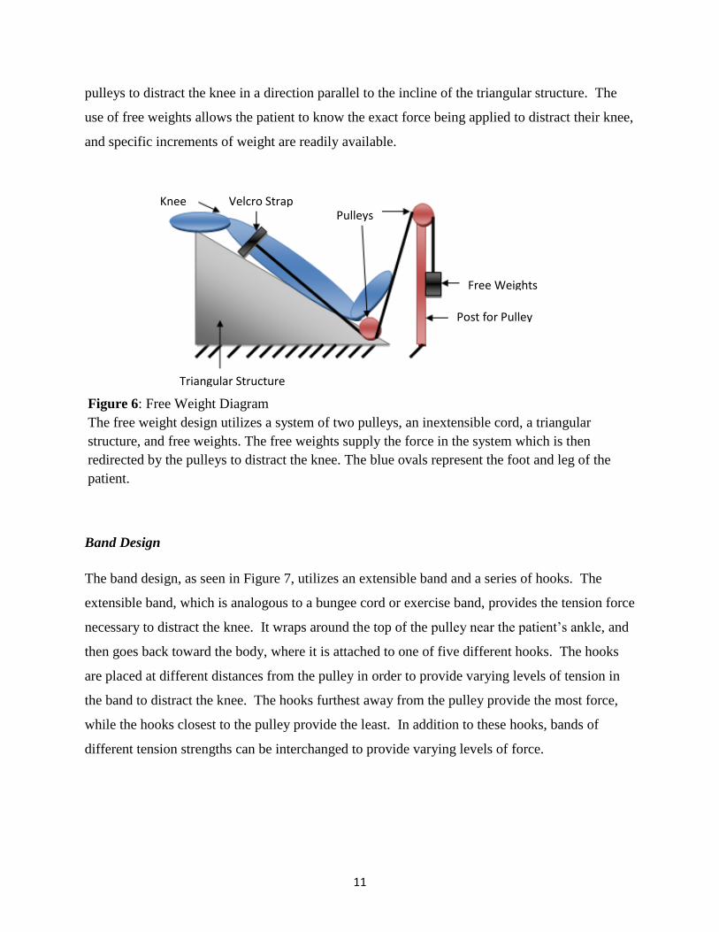
The band design, as seen in Figure 7, utilizes an extensible band and a series of hooks. The
extensible band, which is analogous to a bungee cord or exercise band, provides the tension force
necessary to distract the knee. It wraps around the top of the pulley near the patient’s ankle, and
then goes back toward the body, where it is attached to one of five different hooks. The hooks
are placed at different distances from the pulley in order to provide varying levels of tension in
the band to distract the knee. The hooks furthest away from the pulley provide the most force,
while the hooks closest to the pulley provide the least. In addition to these hooks, bands of
different tension strengths can be interchanged to provide varying levels of force.
Figure 6: Free Weight Diagram
The free weight design utilizes a system of two pulleys, an inextensible cord, a triangular
structure, and free weights. The free weights supply the force in the system which is then
redirected by the pulleys to distract the knee. The blue ovals represent the foot and leg of the
patient.
Knee Velcro Strap Pulleys
Free Weights
Post for Pulley
Triangular Structure
12
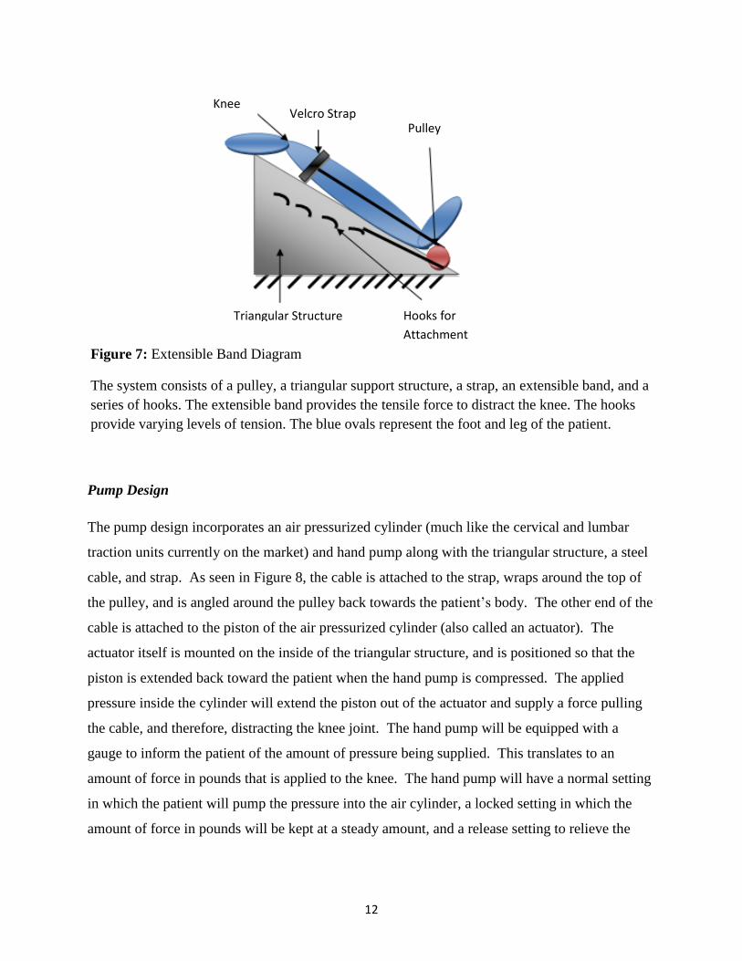
Pump Design
The pump design incorporates an air pressurized cylinder (much like the cervical and lumbar
traction units currently on the market) and hand pump along with the triangular structure, a steel
cable, and strap. As seen in Figure 8, the cable is attached to the strap, wraps around the top of
the pulley, and is angled around the pulley back towards the patient’s body. The other end of the
cable is attached to the piston of the air pressurized cylinder (also called an actuator). The
actuator itself is mounted on the inside of the triangular structure, and is positioned so that the
piston is extended back toward the patient when the hand pump is compressed. The applied
pressure inside the cylinder will extend the piston out of the actuator and supply a force pulling
the cable, and therefore, distracting the knee joint. The hand pump will be equipped with a
gauge to inform the patient of the amount of pressure being supplied. This translates to an
amount of force in pounds that is applied to the knee. The hand pump will have a normal setting
in which the patient will pump the pressure into the air cylinder, a locked setting in which the
amount of force in pounds will be kept at a steady amount, and a release setting to relieve the
Figure 7: Extensible Band Diagram
The system consists of a pulley, a triangular support structure, a strap, an extensible band, and a
series of hooks. The extensible band provides the tensile force to distract the knee. The hooks
provide varying levels of tension. The blue ovals represent the foot and leg of the patient.
Triangular Structure Hooks for
Attachment
Pulley Velcro Strap
Knee
13
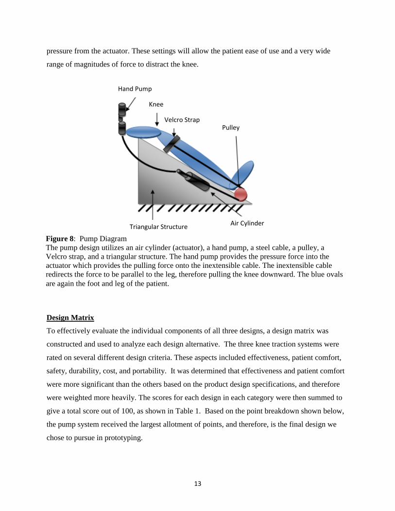
pressure from the actuator. These settings will allow the patient ease of use and a very wide
range of magnitudes of force to distract the knee.
Design Matrix
To effectively evaluate the individual components of all three designs, a design matrix was
constructed and used to analyze each design alternative. The three knee traction systems were
rated on several different design criteria. These aspects included effectiveness, patient comfort,
safety, durability, cost, and portability. It was determined that effectiveness and patient comfort
were more significant than the others based on the product design specifications, and therefore
were weighted more heavily. The scores for each design in each category were then summed to
give a total score out of 100, as shown in Table 1. Based on the point breakdown shown below,
the pump system received the largest allotment of points, and therefore, is the final design we
chose to pursue in prototyping.
Figure 8: Pump Diagram
The pump design utilizes an air cylinder (actuator), a hand pump, a steel cable, a pulley, a
Velcro strap, and a triangular structure. The hand pump provides the pressure force into the
actuator which provides the pulling force onto the inextensible cable. The inextensible cable
redirects the force to be parallel to the leg, therefore pulling the knee downward. The blue ovals
are again the foot and leg of the patient.
Knee
Pulley Velcro Strap
Triangular Structure
Hand Pump
Air Cylinder

14
Effectiveness
The purpose of our design is to apply a force to the lower leg to distract the knee joint for 15-20
minutes, multiple times per day. As the most important category, effectiveness was given a
weight of 25 points in the design matrix because it determines the ultimate performance of the
device. The pump design scored the highest, receiving 23 out of a possible 25 points. It was
closely followed by the free weight design (21 points) and the band design (20 points). The
pump design scored the highest because it would be the most effective in supplying a constant
force on the knee, and could uphold that force for an extended period of time. The free weight
design scored the second-highest in this category because while it would be effective and use
gravity to its advantage, the device might apply a greater instant force immediately after weights
are added, rather than one that would be gradual and constant. The band design received the
fewest points because over time, the bands would lose elasticity and therefore, be less effective.
Patient Comfort
Patient comfort is a significant aspect of the design, and was given 20 points in the design
matrix. The comfort of patients while using this device is important because it will be used in the
Weight Criteria Pump Design Band Design Weight Design
25 Effectiveness 23 20 21
20 Patient Comfort 19 19 18
15 Safety 12 13 8
15 Durability 14 10 11
15 Cost 7 13 10
10 Portability 7 5 3
100 Total 82 80 71
Table 1: Design Matrix
This design matrix breaks down each design based on certain criteria that we believe are
important for our design. The maximum point values are indicated in the left-most row,
and the total points allotted out of 100 are specified in the bottom row.
15
patient’s home multiple times per day, and if the patient is not comfortable while performing
distraction, they likely will not use the product. The pump and band designs were both given 19
points in the area of patient comfort. Both designs will provide comfortable padding for the
knee, and because the distraction force will be applied gradually in both designs, patient comfort
will be optimized. The free weight design received a slightly lower value of 18 points for patient
comfort because it may be uncomfortable for a patient with knee osteoarthritis to lift a free
weight onto the pulley system.
Safety
Safety was also weighted at 20 points in the design matrix because our design will be used by
individuals as a form of therapy, and should not cause any pain or harm. The force supplied by
the device should not distract any joints other than the desired knee joint. The pump design
scored the highest in this category with 18 points because the distraction force would be applied
gradually, and the actuator would be unlikely to cause physical harm to the patient while in use.
The band design scored the next highest with 17 points because the distraction force would still
be applied gradually, but bands may snap causing possible injury to the patient. The free weight
design received eight points and would be the least safe due to the fact that the traction force
would be instantly applied, and that weights can be dropped on the hands or feet.
Durability
As requested by our client, the device must be usable for a minimum of 15 years, and ideally a
lifetime. Therefore durability must be included in the design matrix. The use of any machine
over an extended period of time causes expected wear on individual parts, but the chosen device
must minimize wear to each component. Durability was given a maximum of ten points in the
design matrix because the patients will be using the device at home and will be in charge of the
maintenance of their own equipment. The pump design was given nine points because it was
determined that the chance of failure was rather low since the pump would not be applying an
excessive amount of force. Scoring the next lowest was the free weight design, which received
six points. It was suspected that the rope may wear out over time since it must hold a large
amount of weight in the air. The band design was given three points, the least amount in this
16
category because the bands may stretch and break over time which would require the patient to
either purchase multiple bands or replace them frequently.
Cost
In order for the device to be marketable, it must be cost effective. Furthermore, to make the
purchase of this device a better option than having knee replacement surgery, it should be low in
cost while still using durable materials. Thus, cost was given a value of 15 points in the design
matrix. The band design was given the highest value of 13 points because elastic bands are
readily available and inexpensive. Ten points were given to the free weight design because
weights would be more expensive than the bands, and the pulley design would cost more to
manufacture. Finally the pump design was given only seven points, the lowest value attained,
because the air cylinder, gauge, and hosing components are significantly more expensive than
the bands or free weights.
Portability
Portability was seen as a less important aspect of our design and was thus given only ten points
in the design matrix. The device will need to be used in the patient’s home, and would not likely
need to be transported from place to place. It should be fairly lightweight so that the patient may
easily lift the device. The device should also be easily stored so that it is out of the patient’s way
when not in use. The band design was given the highest value of seven points in this category
because it would be the most lightweight and have the least amount of components. The pump
design was given the next highest value of five points because although it is still relatively light
weight, it includes the loose cable, Velcro strap, and hand pump components that would hinder
portability. Finally, as it would be quite difficult to transport free weights, the weight design was
given the lowest value of three points.
Testing and Results
Testing
Initial qualitative testing on the design prototype was conducted by team members on
Wednesday, December 7, 2011. Overall, 16 subjects participated in the study, and all were

17
students of the University of Wisconsin-Madison. These participants varied in age from 18 to
22, in height from 5’4” to 6’2”, and in weight from 120 lbs to 210 lbs. Each subject used the
device for five minutes, and performed distraction with an average force of 63.7 pounds.
This average force corresponds to a
PSI of 20, as can be seen in Figure 9.
The test subjects were then asked to
complete an evaluation form
containing questions about their
experience with the device (see
Appendix). Each question included a
rating scale of one to five, where a one
signified a negative response while a
five represented an exceptional
experience (see Appendix). Comfort, usability, and overall
effectiveness ratings were collected from each patient,
averaged, and then analyzed to determine where future
adjustments should be made. The results of these tests are
displayed in Table 3.
Discussion
As seen in Table 2, positive feedback and high scores were observed for each category. The
highest scoring category in our testing was patient comfort with a score of 4.4375. It was
indicated that the padding and vinyl fabric cover were pleasing to the subjects, which led to this
high rating. The overall effectiveness rating scored in the middle with an average of 4.25.
During testing, we received many comments indicating that the device is successful in separating
the joints in the knee. However, none of the test subjects reported having knee osteoarthritis, so
Ratings Average Std. Dev.
Overall 4.25 0.5774
Comfort 4.4375 0.6292
Usability 4.125 0.7188
Table 2: Testing Results
Qualitative values averaged from 16 test subjects.
Rating scale is from one to five with one
corresponding to a low rating, and five as the highest.
Figure 8: Conversion of pounds of
force to PSI used to distract the
knee in our device. 0
5
10
15
20
25
0 20 40 60 80
PS
I
Pounds
Calibration Curve
Figure 9: Calibration curve between PSI and pounds
of force.

18
they were not able to compare joint pain before and after the joint distraction. The lowest scoring
category included in our survey was usability. Judging from observations and the comments
received, this lower score could be attributed to a variety of different problems that arose with
the prototype. First, the majority of the test subjects experienced difficultly when putting on and
fastening the leg strap, requiring another person’s assistance. Additionally, the cables frequently
slipped out of the pulley tracks, also requiring another person to adjust the apparatus before
distraction could take place. A slight leak in the connection between the hand pump and air hose
also hindered usability because it was difficult to maintain a constant distraction force on the
knee. By applying this feedback, changes can be made to improve the functionality and usability
of the knee traction device.
In the future, a similar evaluation will be given to physical therapy patients suffering from knee
osteoarthritis when using our device for distraction therapy. The patient will be instructed to use
the device for a period of seven days, and joint distraction will be performed twice a day for 20
minutes. Patients will fill out the evaluation every day, rating their experience with the device
from one to five, similar to the procedure our test subjects followed. Comfort, usability, and
overall effectiveness ratings will be collected from each patient, averaged and analyzed. If there
is no change in comfort or pain, adjustments will be made in order to increase the effectiveness
of the device in these areas. Tests will be run on a multitude of users ranging in height, weight
and age to ensure that the device can safely be
used by all patients.
Although these patient evaluation forms
provide feedback and qualitative data, in the
future, quantitative analysis will be
completed as well. Our team plans to
compare an x-ray of the patient’s knee with
the device to an x-ray of the patient’s knee without using the device, an example of which is seen
in Figure 10. An image of the distracted knee would enable us to see the physical distance
between the bony ends of the tibia and femur when a distraction force is applied and compare it
to the natural space between the joints without application of this force [9]. After consulting our
client and experts in the field of physical therapy and orthopedics, we can determine the distance
between the bones that will optimize distraction treatment. Using this joint space data, a
Figure10: An x-ray of a distracted knee from
invasive knee osteoarthritis treatment [8].

19
calibration curve can be constructed relating a person’s weight to the force required to reach this
joint space. Ultimately categorizing this data according to height and weight will allow
necessary adjustments to be made to the device to allow a comfortable and effective experience
for a multitude of users.
Future Work
There are many items that still need to be addressed before our device fully meets the established
product design specifications. First, our current device is fabricated out of wood, and although it
is stable and durable, the device is far too heavy. To make it more convenient for the patient to
transport, in a future design the device should be constructed from lightweight plastics or metal.
Ideally, the device will also be collapsible for easy storage in the home. Second, it will be
necessary to develop a strap and cable system that is adjustable to accommodate patients varying
in height and weight. The current strap is permanently fixed to the cables, causing the wire rope
to often run down the back or front of the leg when being used by patients with smaller or larger
legs. Also, a barrier to keep the cables in their respective pulley tracks during patient setup and
throughout the time the device is in use should be an addition to the device. However, the
component that requires the most revision in future prototypes is the hand pump and its
respective connections. The hand pump used with the current device is normally used for
bicycles, and the threads are not compatible with the rest of the hosing system. In the future, it
will be necessary to either fabricate a custom adapter to attach the pump to the gauge, or find a
hand pump with pipe threads to make the connection airtight, more durable, functional, and
visually appealing. Additionally, the hand pump should have a release mechanism to allow the
air cylinder to retreat to its original position after distraction. Currently, to release the air from
the cylinder, it is necessary to unscrew one of the hose connections from the adaptor. Therefore,
to improve the safety and usability of the device, a release valve is imperative in future
prototypes. In all, there are various improvements that can be made to the device in the future,
and with these modifications, it could soon be a marketable device.

20
Cost
The fabrication of our device was based on a hand pump design with an air cylinder. As
determined by our client, the final budget for the device is $500. The costs in building our
prototype include:
Item Purchased from Item # Price Quantity
Cast wire rope clips McMaster-Carr 31985T71 $1.41 2
Gauge adaptor McMaster-Carr 50785K226 $4.68 1
Accuracy gauge McMaster-Carr 4026K26 $55.54 1
Air Cylinder McMaster-Carr 6498K954 $35.86 1
Pulley McMaster-Carr 9466T75 $5.85 2
Coated Cable McMaster-Carr 8923T511 $0.92/ft 10 ft
Foot Brackets McMaster-Carr 6498K34 $3.95 2
Hose McMaster-Carr 5304K388 $13.19 5 ft
Thread size adaptor McMaster-Carr 48805K252 $11.22 1
Pulley McMaster-Carr 9466T73 $8.35 2
Adaptor McMaster-Carr 97088A205 $2.45 1
Rod End Grainger 6G173 $10.26 1
Mueller ltb strap Amazon $9.81 1
High density pads JoAnn Fabric $13.99 1 yd x 1 yd
MedBlue Marine
Vinyl
JoAnn Fabric $16.99 1 yd x 1 yd
2x4x6 SPF Construct
Menards $1.39 5
3/4" min 7.9 S Menards $9.59 1
8 oz. tightbond II
Wood
Menards $2.98 1
Multi-mate 10x2-1/2
ph
Menards $5.99 1
1/2" Chisel point
staples
Menards $2.29 1
Adjustable knee brace Dick’s Sporting Goods $12.99 1
Avenir air pump Dick’s Sporting Goods $14.99 1
Final Total = $298.42
Table 3: Contains prices of materials for construction of our
device.
21
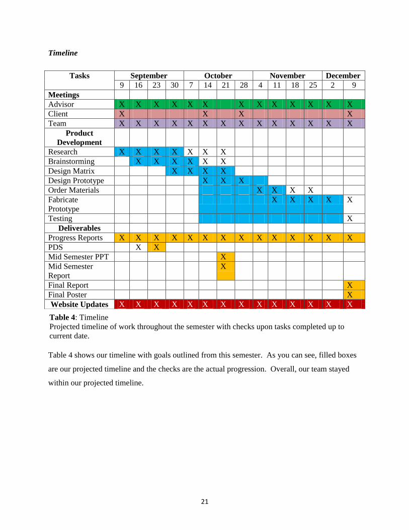
Timeline
Table 4 shows our timeline with goals outlined from this semester. As you can see, filled boxes
are our projected timeline and the checks are the actual progression. Overall, our team stayed
within our projected timeline.
Tasks September October November December
9 16 23 30 7 14 21 28 4 11 18 25 2 9
Meetings
Advisor X X X X X X X X X X X X X
Client X X X X
Team X X X X X X X X X X X X X X
Product
Development
Research X X X X X X X
Brainstorming X X X X X X
Design Matrix X X X X
Design Prototype X X X
Order Materials X X X X
Fabricate
Prototype
X X X X X
Testing X
Deliverables
Progress Reports X X X X X X X X X X X X X X
PDS X X
Mid Semester PPT X
Mid Semester
Report
X
Final Report X
Final Poster X
Website Updates X X X X X X X X X X X X X X
Table 4: Timeline
Projected timeline of work throughout the semester with checks upon tasks completed up to
current date.

22
References
[1] Interna F., Van Roermund PM, Marijnissen ACA, et al. Tissue structure modification in knee
osteoarthritis by use of joint distraction: an open 1-year pilot study. Annals of the
Rheumatic Diseases (May, 2011).
[2] Traction tables and units: tables and units. (2011). Retrieved 10/23, 2011, from
http://www.keitzer.com/Qstore/Qstore.cgi?CMD=009&DEPT=1137884894&CAT=0000
54&BACK=A0007A1B01137884894B
[3] Saunders Cervical Traction Device. (2011). Retrieved 10/23, 2011,
http://www.empi.com/empi_products/detail.aspx?id=230
[4] Saunders Lumbar Traction Device. (2011). Retrieved 10/23, 2011, from
http://www.empi.com/empi_products/detail.aspx?id=232
[5] Types of arthritis. (2011). Retrieved 10/23, 2011, from http://www.vimovo.com/types-of-
arthritis.aspx
[6] Innovative Ways to Detect Osteoarthritis Developed. Elements 4 Health. Aug. 2010.
Retrieved from http://www.elements4health.com/innovative-way-to-detect-osteoarthritis-
developed.html [7] Knee OsteoArthritis Treatment. Woodward Medical Center. 2011. Retrieved from
http://www.woodwardmedical.com/knee-osteoarthritis.html [8] Diseases and conditions. (2011). Retrieved 10/23, 2011, from
http://www.mayoclinic.com/health/osteoarthritis/
[9] Deie, M., Ochi, M., Adachi, N., Kajiwara, R., Kanaya, A. A new articulated distraction
arthroplasty device for treatment of the osteoarthritic knee joint: A preliminary report.
Arthroscopy: The Journal of Arthroscopic and Related Surgery. (August 2007).
[10] Skinner, Kim. Interview by studiomelt.com. studiomelt. (2011). Retrieved 10/23, 2011,
from http://studiomelt.com/kim.html
[11] Joint Distraction May Delay Need for Joint Replacement in Advanced Osteoarthritis.
(2006). Retrieved 12/1, 2011, from
http://www.mskreport.com/articles.cfm?articleID=905
[12] Cleland, J., Whitman, J., Fritz, J., Palmer, J. Manual physical therapy, cervical traction,
and strengthening exercises in patients with cervical radiculopathy: A case series. Journal
of Orthopedic and Sports Physical Therapy. (December 2005).
[13] Gruben, Kreg. Personal Interview. 3 Oct. 2011.
[14] Fung, Yuan-cheng. Biomechanics Mechanical Properties of Living Tissues. 2nd
ed. Berlin:
Springer, 1993. Print.
[15] Ozkaya, N., Nordin, M., Fundamentals of Biomechanics, 2nd
ed. New York: Springer, 1999.
Print.

23
Appendix
Creating distraction at the knee joint: a treatment option for osteoarthritis (Knee Traction)
Group Members: Kelsi Bjorklund, Jacob Stangl, Taylor Lamberty, Amy Martin, Lindy
Couwenhoven
Advisor: Tracy Puccinelli, Ph.D.
Function:
Knee osteoarthritis affects millions of Americans and people around the world. It is a
painful, degenerative disease for which there is no cure. Thus far, no treatment option has been
shown to halt or reverse tissue damage. However, joint distraction has been shown to increase
cartilage thickness, decrease denuded bone area, decrease pain and improve functional ability. It
is a procedure that gradually separates the two bony ends of a joint for a specified period of time.
This principal can be applied to the knee joint. We will be creating a non-surgical device that can
be used as a home-based intervention to create joint distraction in the knee. No such device
currently exists. The theory is that when used regularly, someone could potentially delay or
eliminate the need for a knee replacement.
Client Requirements:
A device that will distract the knee in order to stop or slow the progression of
osteoarthritis.
A device simple enough to be used at home by patients who may have limited mobility.
Reach a maximum of 311.4 N (70 pounds) of pressure to distract the knee joint apart.
Fit a wide range of patients in weight and size.
Provide a constant force to maintain distraction for 20 minutes.
Keep knee at a 30° angle from the horizontal, or the “open pack” position, to optimize
separation of the knee joint.
Take caution to not distract the ankle and hip joints.
1. Physical and Operational Characteristics
A. Performance Requirements: The device must be able to keep a patient’s knee
distracted for a period of 20 minutes. The device must also reach a maximum pull of 311.4 N (70
pounds) and be easily stored in the home. It must be functional for a wide range of patients
regarding size and dexterity.
B. Safety: The device must provide enough pressure to distract the knee but not cause
injury to the joint or distract the hip or ankle. It also must be stable so that when force is applied,
there is no extra movement that would put the user at risk.

24
C. Accuracy and Reliability: The device must be able to maintain a constant pressure up
to 311.4 N (70 pounds) for a period of 20 minutes, multiple times a day. The force used to
distract the knee joint will be easily adjusted by a patient based on their needs. The knee must
also be kept at an angle of 30 ° to maintain an “open pack” position.
D. Life in Service: The device should maintain function for a minimum of 15 years.
Ideally, the product should last a lifetime.
E. Operating Environment: The finished device will be used in the home on a firm, flat
surface, and the user should be seated in a firm chair that is 0.5 meters (19 inches tall).
F. Ergonomics: As this device will be used by a range of patients at varying heights and
weights, ergonomics is extremely important. The device must be functional for anyone weighing
from 100 to 400 pounds. The prototype must also be adjustable, user friendly, and easily
transported.
G. Size: The traction unit must be shorter in length than one meter, 0.5 meters tall, and
wide enough to accommodate a wide range of leg sizes.
H. Weight: The traction unit must be lightweight so that it can be lifted by a patient who
suffers from osteoarthritis in the knee. However, it should not be so lightweight that it impedes
functionality or usability.
I. Materials: The materials used should be strong and durable for the device to last many
years, as well as be nonabrasive to the skin. Materials used are nylon coated cables, wood
covered in foam padding with a layer of vinyl fabric, pulleys, cotton straps, Velcro straps,
cylinder mounting clips, and an air cylinder with a hand pump and gauge.
J. Aesthetics, Appearance and Finish: Since this device will be used in homes, it must
be aesthetically pleasing and have a smooth, streamline design.
2. Production Characteristics A. Quantity: We will be constructing one device.
B. Target Product cost: The target product cost will be at or below $500.
3. Miscellaneous A. Standards and Specifications: If marketed, the product will require approval from
the FDA.
B. Customer: The intended customer for this device is anyone who may suffer from
knee osteoarthritis that would prefer a way to ease their pain and prolong the amount of time
before knee replacement surgery is needed by using an at home system. The patients will be of
varying height, weight and ability level, therefore the product must be compatible to many
different body types. All of these requirements must be considered in designing a final product.

25
C. Patient-related Concerns: The device must not be harmful to the user in any way and
be comfortable so as to not put the patient in any more discomfort than already caused by their
knee osteoarthritis.
D. Competition: Currently, there is no competition as there is no at home product for
distracting the knee available on the market. Knee distraction is only done in a clinical setting
and even then is very cumbersome to execute.

26
Knee Traction Unit Evaluation Form
Age:
Weight:
Height:
Sex:
How long did you use the device for? (minutes)
What was the PSI reading when you used the device?
Additional comments:
After using this device I feel (Please Circle):
1 2 3 4 5
Please rate the comfort of the device (Please Circle):
1 2 3 4 5
Please rate the usability of this device (Please Circle):
1 2 3 4 5
Note:
By signing this form I acknowledge that I am aware that my name and information stated on this page
will not be used in any form of publication or presentation. I also release the following parties from
liability resulting from my participation in this study: Kelsi Bjorklund, Lindy Couwenhoven, Taylor
Lamberty, Amy Martin, Jacob Stangl, and the University of Wisconsin-Madison.
Signature: Date:
Same or worse No pain, 100%
better
Awkward, leg was
strained during use
My leg did not feel strained
Would not be able to use the
device without assistance
Device was extremely user
friendly