creep behaviour of polyamide in selective laser sinteringedge.rit.edu/edge/p10551/public/sff/sff...
TRANSCRIPT
CREEP BEHAVIOUR OF POLYAMIDE IN SELECTIVE LASER SINTERING Eef Moeskops, Nico Kamperman, Bart van de Vorst, Rik Knoppers
TNO Industrial Technology
De Rondom 1, P.O. Box 6235, 5600 HE Eindhoven, The Netherlands Reviewed, accepted August 19, 2004
ABSTRACT
The use of Rapid Prototyping technology to produce fully-functional end use products (Rapid Manufacturing) requires understanding of the material's time dependency. Creep is the time dependent strain as a result of a constant load. Creep behaviour of sintered polyamide-12 processed by the Selective Laser Sintering process has been investigated. To study the effect of temperature on this material, tests have been performed at room temperature as well as at elevated temperatures of 60°C and 100°C. Although the SLS processed material is more sensitive to creep than most other thermoplastics it is shown to be affected less than injection molded polyamide-12, which has been tested as a reference. The results show an almost linear behaviour on a logarithmic time scale, which enables the creep behaviour of SLS processed polyamide-12 to be predicted for at least 11 years.
INTRODUCTION
Rapid Manufacturing (RM) is the production of fully-functional end-use products using Rapid Prototyping technology. One of the techniques that was found to have potential to be utilised as an RM process is Selective Laser Sintering (SLS). With SLS, a powder - having particle sizes in the range of 20~100 µm - is spread out onto a build platform that steps down for each layer of the model. A CO2 laser selectively heats up the powder to a temperature just above the melting point, bonding the particles in one layer together as well as to the layer below. The whole process is kept inside a heated chamber at a temperature close to the melt temperature of the powder, so that the laser needs to impart only a small temperature increase to ensure bonding.
The layered manufacturing and the polyamide material are at the base of some characteristic RM-material properties, such as: brittle failure, anisotropy, temperature dependency and moisture absorption. These material properties can be analysed using 'short-term' tests such as tensile tests. Designing for RM also requires understanding of the time-dependent 'long-term' properties. After all, the product needs to meet the requirements even after a period of time in service.
An important 'long-term' property is tensile creep, which is the strain (∆l+ ∆c) as function of time (t), as a result of a constant load (F). See Figure 1.
60

EXPERIMENTAL PROCEDURE Because of the high relevance to the number of creep tests that have to be performed, it is necessary to evaluate whether the samples behave in an isotropic or anisotropic manner. Standard dumb-bell-shaped specimens (ISO 527-1) have been produced in six directions, as indicated in Figure 2. These specimens were produced on a 3D Systems' Vanguard HS with layer thickness of 0.1mm, using virgin Duraform powder and standard machine build parameters.
The tensile test results reveal only little variation between XY, XZ, YX and YZ built
specimens and between ZX and ZY built specimens. Therefore it was chosen to conduct creep tests only with specimens built in ZX and YX directions, representing the worst-case and best-case directions for 'short-term' properties.
As a reference, injection molded Duraform specimens have been produced using an Arburg 320S 500-150 at an injection temperature of 270°C, 70 bar ram pressure leading to 525 bar effective injection pressure, 400 bar hold pressure reducing to 100 bar in 9.30 seconds. Tensile tests show that the injection molded specimens are less stiff (about 1400 MPa) and more ductile (having an elongation at break of almost 300%).
∆c ∆l ∆l
l0 l0+∆l+∆c l0+∆l
Time = 0 Time = 1 min Time = t
F F
Figure 1: Tensile creep.
Figure 2: Different orientations of fabrication and their tensile behaviour (averages of five tests per direction). The X-axis denotes the laser scanning direction, as the Z-axis denotes the layer build direction.
0
10
20
30
40
50
0 10 20 30 40Strain (% )
Stre
ss (M
Pa)
X
Z
Y
YZ
YX
XZ
ZY ZX
XY
YX
ZY
YZ XY ZX
XZ Injection moulded
61
The tensile creep behaviour has been tested according to ISO 899-1, with identical specimens as used in the tensile tests. These specimens were connected to a frame at one side. Stresses have then been applied by attaching loads to the other side. Tests at room temperature (23°C) have been conducted with both SLS and injection molded material at approximately 12.5%, 25%, 37.5%, 50% and 80% of the material's Ultimate Tensile Strength, i.e. at 5, 10, 15, 20 and 35 MPa respectively. These tests have been conducted twice for each stress level. The extension of the specimens was measured over time by using a cathetometer. Each sequence was limited to 1000 hours.
Due to the moisture uptake of the material it is of no use to conduct creep tests with dry-as-molded specimens (ISO-1874-2). It was therefore chosen to carry out the creep tests at room temperature with moistened specimens. This moist state was achieved by immersing the specimens in water at 60°C for 24 hours, after which they were stored in the test environment (23°C, 50% RH) for at least 24 hours.
The temperature dependent mechanical behaviour of nylon parts makes it necessary to conduct tests at a wide range of temperatures. In this study, also creep tests at elevated temperatures were conducted at high temperature (100°C) and at medium temperature (60°C). Moistening the specimens would be unnecessary, since this moist will evaporate at elevated temperatures.
The elevated temperatures were obtained by testing the specimens within a heated chamber. The temperature in this heated chamber was controlled using an adjustable convection heater. Thermocouples attached to every clamp recorded the real temperature at every specimen. Before each test, the specimens were conditioned in the preheated environment for over 24 hours.
At elevated temperatures the stress levels were set to 2.5, 5, and 10 MPa.
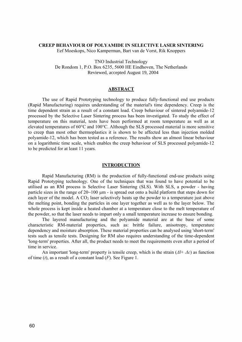
RESULTS
The creep results are shown in Figure 3. From these curves it can be concluded that the
differences between YX and ZX built specimens are negligible for small loads. These differences increase with increasing load and temperature.
Raising the temperature reveals an increased initial creep response and creep rate. After 100 hours testing the 10 MPa tests show a strain of 1.7% at 23°C, 2.5% at 60°C and 3.9% at 100°C. Due to mechanical slip of clamps, the measurement of the YX specimen at 100°C had to be stopped after 1 hour.
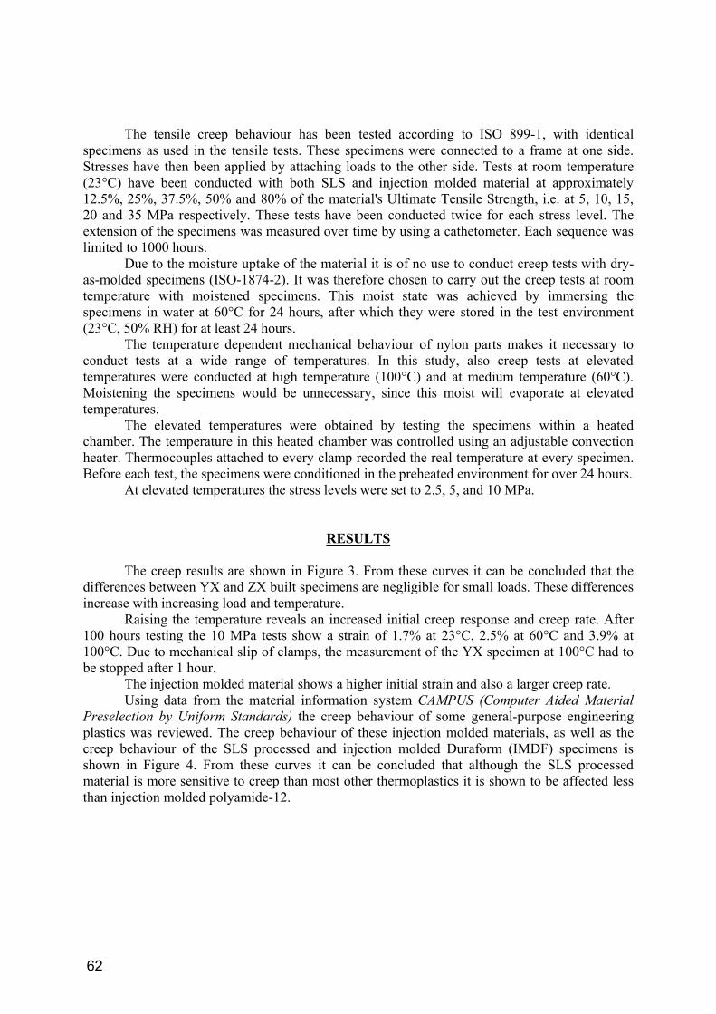
The injection molded material shows a higher initial strain and also a larger creep rate. Using data from the material information system CAMPUS (Computer Aided Material
Preselection by Uniform Standards) the creep behaviour of some general-purpose engineering plastics was reviewed. The creep behaviour of these injection molded materials, as well as the creep behaviour of the SLS processed and injection molded Duraform (IMDF) specimens is shown in Figure 4. From these curves it can be concluded that although the SLS processed material is more sensitive to creep than most other thermoplastics it is shown to be affected less than injection molded polyamide-12.
62
0
1
2
3
4
5
6
0.01 0.1 1 10 100 1000Log time (hours)
Stra
in (%
)
0
1
2
3
4
5
6
0.01 0.1 1 10 100 1000Log time (hours)
Stra
in (%
)
SLS, 23°C Injection Molded, 23°C
SLS, 60°C SLS, 100°C
0
1
2
3
4
5
6
0.01 0.1 1 10 100 1000Log time (hours)
Stra
in (%
)
Figure 3: Creep behaviour of YX ( ), ZX ( ) and injection molded ( ) specimens.
0
1
2
3
4
5
6
0.01 0.1 1 10 100 1000Log time (hours)
Stra
in (%
)
5 MPa
10 MPa
15 MPa
20 MPa
35 MPa
10 MPa 5 MPa
2.5 MPa
10 MPa 5 MPa 2.5 MPa
20 MPa 10 MPa 5 MPa
Figure 4: Isochronous curves of several engineering plastics after 1000h, 23°C.
SLS YX SLS ZX
PA-12
PA-66
PA-6 GF30 PC
ABS
SAN PA-6
PS
Several engineering plastics, 1000h, 23°C
0
10
20
30
40
0 0.5 1 1.5 2 2.5 3
Strain (% )
Stre
ss (M
Pa)
IMDF
63
ANALYSIS OF THE MATERIAL
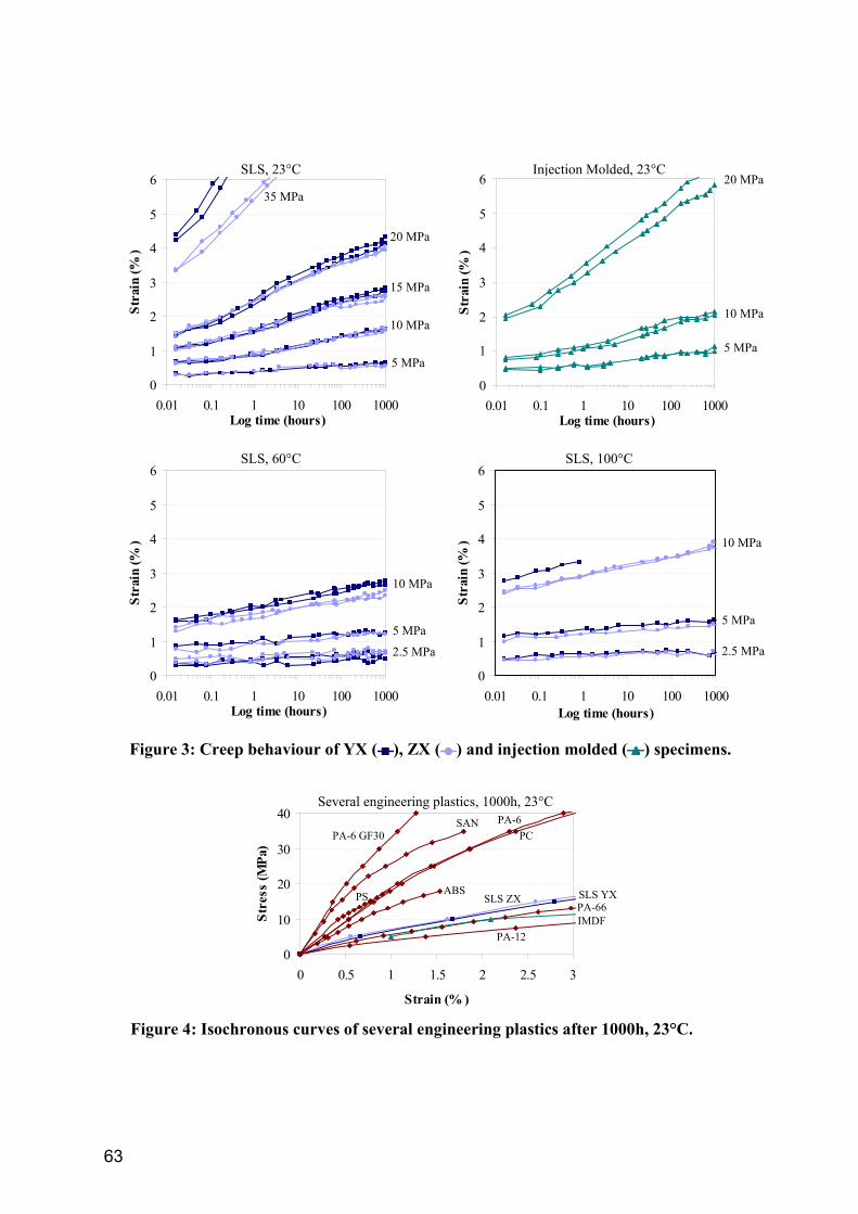
Using a microtome, 5µm thick slices have been planed off from the reported materials.
These slices have been applied to a cover glass and observed using a light microscope (with oblique as well as with polarised light), as can be seen in Figure 5.
These pictures show the presence of both spherulites and kernels of particles within the
SLS processed material. Near the edge of an SLS part spherulites can be found with the size of 50µm, which is equal to the size of an individual powder particle before sintering. The injection molded material shows to have smaller spherulites and no kernels of particles can be seen.
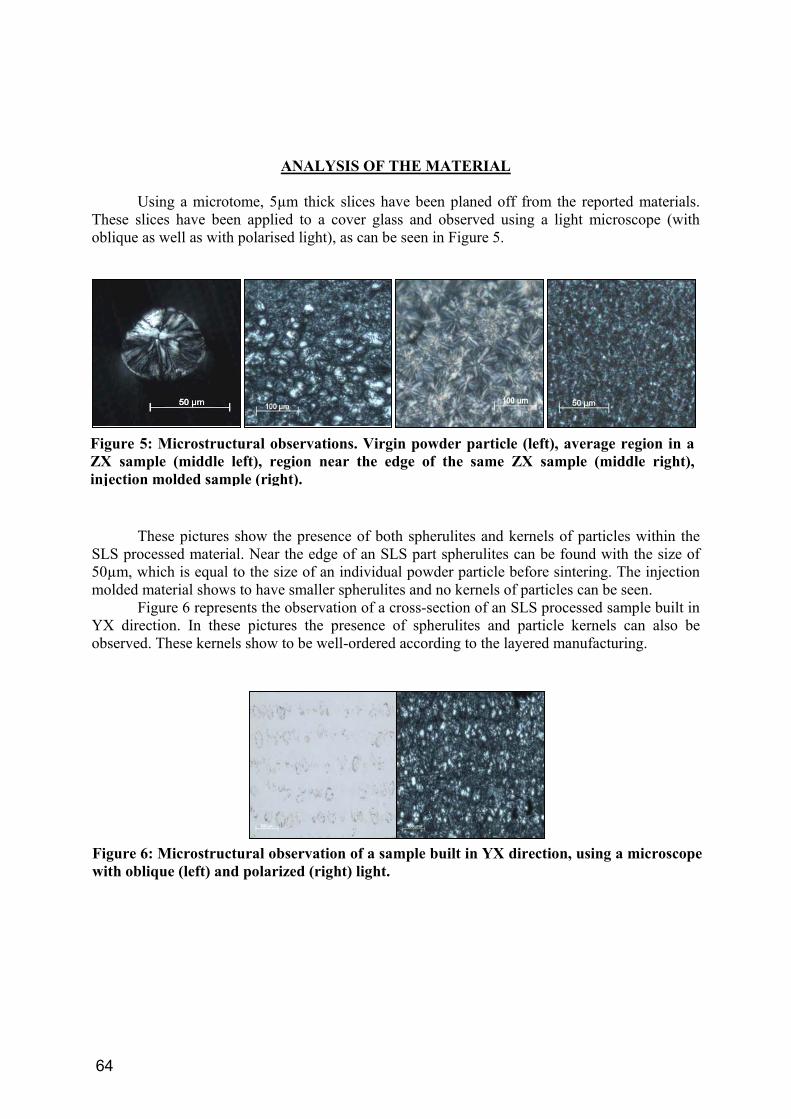
Figure 6 represents the observation of a cross-section of an SLS processed sample built in YX direction. In these pictures the presence of spherulites and particle kernels can also be observed. These kernels show to be well-ordered according to the layered manufacturing.
Figure 6: Microstructural observation of a sample built in YX direction, using a microscope with oblique (left) and polarized (right) light.
Figure 5: Microstructural observations. Virgin powder particle (left), average region in a ZX sample (middle left), region near the edge of the same ZX sample (middle right), injection molded sample (right).
64
DISCUSSION
Although tensile tests show large differences between mechanical behaviour of YX and ZX built specimens, these differences are not reflected in the creep results. Only with creep tests at higher loads and temperatures the YX built specimens show to perform not as good as the ZX built specimens.
There are two topics concerning the anisotropic behaviour of SLS Duraform material. Influence is exerted by the weak bonding between layers [9] as well as by the presence and distribution of particle kernels within the material.
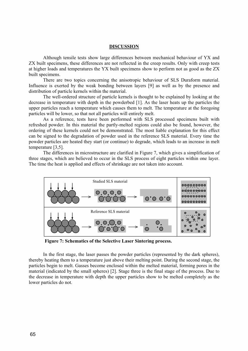
The well-ordered structure of particle kernels is thought to be explained by looking at the decrease in temperature with depth in the powderbed [1]. As the laser heats up the particles the upper particles reach a temperature which causes them to melt. The temperature at the foregoing particles will be lower, so that not all particles will entirely melt.
As a reference, tests have been performed with SLS processed specimens built with refreshed powder. In this material the partly-melted regions could also be found, however, the ordering of these kernels could not be demonstrated. The most liable explanation for this effect can be signed to the degradation of powder used in the reference SLS material. Every time the powder particles are heated they start (or continue) to degrade, which leads to an increase in melt temperature [3,5].
The differences in microstructure are clarified in Figure 7, which gives a simplification of three stages, which are believed to occur in the SLS process of eight particles within one layer. The time the heat is applied and effects of shrinkage are not taken into account.
In the first stage, the laser passes the powder particles (represented by the dark spheres),
thereby heating them to a temperature just above their melting point. During the second stage, the particles begin to melt. Gasses become enclosed within the melted material, forming pores in the material (indicated by the small spheres) [2]. Stage three is the final stage of the process. Due to the decrease in temperature with depth the upper particles show to be melted completely as the lower particles do not.
Figure 7: Schematics of the Selective Laser Sintering process.
Reference SLS material
Studied SLS material
65
The temperature (and the time this temperature acts upon the material) in the powder bed is too low to arrange a good bonding between the processed layer and its foregoing layer. During this bonding diffusion between the layers has to take place as chains in the melt move with a snake-like motion, called reptation [9]. This random walk configuration causes entanglement between both layers. However, due to the low temperature and the short time in which the chains are able to move, the entanglement between two layers is low in respect to the entanglement of chains within a layer. Increasing the temperature can improve the entanglement between layers as is true for the injection molded Duraform. On the other hand new problems arise when increasing the temperature in the SLS process [6].
Schrauwen[7] concluded that the applied temperatures and cooling rate have their effect on physical ageing and degree of crystallinity. These phenomena are most likely the main causes of the differences in creep behaviour between injection molded Duraform and SLS processed Duraform specimens.
The particle kernels are thought to hinder the stretching of the material [4]. The orientation of these kernels also affects the stretching behaviour, demonstrated by the different creep behaviour of the two materials in Figure 7.
The creep behaviour of the SLS material shows to be almost linear (on a logarithmic time-scale), also with large loads. Using linear extrapolation [8] creep behaviour of SLS material can be described and predicted quite exactly to a maximum of 105 hours, i.e. more than 11 years, on the hand of a 1000h test.
CONCLUSION
Creep behaviour of sintered polyamide-12 processed by the SLS process has been investigated at temperatures of 23°C, 60°C and 100°C. Although the SLS processed material is more sensitive to creep than most other thermoplastics it is shown to be affected less than injection molded polyamide-12, which has been tested as a reference.
Therefore, the SLS processed polyamide-12 may have the potential to be utilised for Rapid Manufacturing. Doing so, one has to keep in mind the anisotropic behaviour of the produced parts. This anisotropic behaviour can be explained by looking at the relatively weak bonding between layers and the presence of partly melted powder particles. The mechanical behaviour of processed Duraform material can be explained by looking at the applied process heat, thermal history of the powder (degradation) and the cooling rate.
ACKNOWLEDGEMENT
The authors acknowledge the Rapid Manufacturing Group of the Loughborough University as well as Amitek for supplying the test samples.
REFERENCES [1] Bugeda, G., Cervera, M., Lombera, G, Numerical prediction of temperature and density
distributions in selective laser sintering processes. Rapid Prototyping Journal, 5:1 21-26 (1999).
66
[2] Childs, T.H.C., Berzins, M., Ryder, G.R., Tontowi, A.E., Selective laser sintering of an amorphous polymer - simulations and experiments. Proc Instn Mech Engrs, 213:B 333-349 (1999).
[3] Choren, J., Gervasi, V., Herman T., Kamara, S., Mitchell, J.. SLS Power Life Study. Solid Freeform Fabrication Symposium, Proceedings. 39-45 (2001).
[4] Dommelen, J.A.W. van. Micromechanics of particle-modified semicrystalline polymers. (2003).
[5] Gornet, T.J., Davis, K.R., Starr, T.L., Mulloy, K.M., Characterization of Selective Laser Sinteringtm Materials to Determine Process Stability. Solid Freeform Fabrication Symposium, Proceedings. 546-553 (2002).
[6] Melvin III, L.S., Das, S., Beaman Jr, S., Video Microscopy of Selective Laser Sintering. Solid Freeform Fabrication Symposium, Proceedings. 34-41 (1994).
[7] Schrauwen, B.A.G. Deformation and failure of semi-crystalline polymer systems. Influence of micro and molecular structure. 5-24 (2003).
[8] Struik, L.C.E. Physical aging in amorphous polymers and other materials. Dissertation. (1977).
[9] Xue, Y.Q., Vervoort, T.A., Lemstra, P.J., Welding Behaviour of Semicrystalline Polymers. 1. The Effect of Nonequilibrium Chain Conformations on Autoadhesion of UHMWPE. Macromolecules 31, 3075-3080 (1998).
67