creme96 update/replacement efforts j.h. adams abstract: the … · 2013-04-10 · creme96...
TRANSCRIPT

CREME96 Update/Replacement Efforts
J.H. Adams
Abstract:
This talk concerns the plans to update the CREME96 model that is currently available on
the WWW. The talk states the reasons for updating CRI_ME. It describes the updates
that are planned, including the single event prediction paradigm, the method of radiation
transport through the spacecraft to the electronic component of interest and the planned
updates to models for the space radiation environment. It also reviews user suggestions
received do date for the update.
https://ntrs.nasa.gov/search.jsp?R=20070032033 2019-05-07T22:19:58+00:00Z

CREME96 Update/Replacement Efforts
presented by Jim Adams
Single Event Effects Symposium, Long Beach, CA, 11 April 2007 1

Outline
• Why Update CREME?o The CREME paradigm and why it does not work
o Examples
• The CREME Replacemento Technical Approach
~ SEE Rate Predictions using RADSAFE
- RADSAFE Implementation Concept
- Structure of MRED - Core of RHESE Tool
- Modeling a Complex Stack - Nuclear Events
o Using MRED to Predict SEE Rates
• Summary
Single Event Effects Symposium, Long Beach, CA, 11 April 2007 2
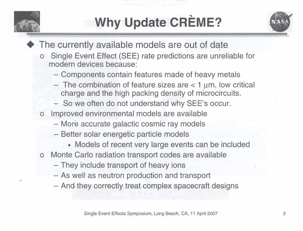
"Why Update CREME?
+ ·The currently available models are out of dqteo Single Event Effect (SEE) rate predictions are unreliable for
modern devices because:- Components contain features made of heavy metals- The combination of feature sizes are < 1 J.lm, low critical
charge and the high packing density of microcircuits.- So we often do not understand why SEE's occur.
o Improved environmental models are available- More accurate galactic cosmic ray models- Better solar energetic particle models
• Models of recent very large events can be includedo Monte Carlo radiation transport codes are available
- They include transport of heavy ions "- As well as neutron production and transport...- And they correctly treat complex spacecraft designs
Single Event Effects Symposium, Long Beach, CA, 11 April 2007 3

"The CREME paradigm
Space Environment Grou,nd TestingIPM-MIN.LET
100 101 102 103 104
LET (MeV-cm'/g)
Direct Ionization: Rectangular Parallelepiped (RPP) modelNuclear Reactions (proton only): Bendel Model
(both are circa 1980)https://creme96.nrl.navy.mil/
Single Event Effects Symposium, Long Beach, CA, 11 April 2007 4

Technical Justification (1)Classical On-Orbit SEE Performance Predictions
Ground TestingI
. Space EnvironmentIPM....MIN.LET
On-Orbit SEE Rate?
Single Event Effects Symposium, Long Beach, CA, 11 April 2007 5

Xe
R.A. Reed, et. alIEEE Trans. Nuc.Sci., vol. 48, no.6, Dec. 2001, pp.2202 - 2209.
RA Reed, et. ai,IEEE Trans. Nuc.Sci., vol. 49, no. 6,Dec. 2002, pp.3038-304fl
Heavy IoneffectsCMOSSRAM
100
120
Protoneffects in
.-1--801 basedmemones
40
10080
30
lETeff (MeV-cm2/mg)
60
2J 40 ffi 80Argo r:J In::il:lem:l (00grees)
20
40
o
Existing Model (\Would P1jedict
Solid Line IA31I~ __~
20
Proton Angle oflnc:idenc:e (Degrees)
Silicon On InsulatorL..-__--.I
c<>
~en;i!10'"I-----+----~d.--l
~8
~
10'" r;========::;---------,'"!
10-5 ,...------------,~---.....
Protons10.6
Effects inOpticalLinks
K.M. Warren, et.allEEE Trans.Nuc. Sci., vol.48, no. 6, Dec.2005, pp. 21252131.
Heavy IonEffects in
~---, SiGe HBTs
•o
~ 1l~~:~- OJ /.'
N~ 10-8 ~ ~ Ar M1 \!:;{ ,/~ 1~~~:i \ \ \/J~ /' '''~o /. ' I'flo. •.1 .,' i /CIl 10-11 1'/: ~;i .!y·:-V)(/(l •.• '.!: \.
10-12-., ··j.f,'\" ,.10-13 --
o 10
Provided by Vendor A
Single Event Effects Symposium, Long Beach, CA, 11 April 2007
MSOfficel
Examples of Breakdown of Existing SEE Models
No ModelWidelyAvailable!
RA Reed, et. al IEEE Trans. Nuc. Sci., vol. 50,no. 6, Dec. 2003, pp. 2184 - 2190
1.E-07 -r:-------------_1.E-oS
Ne 1.E-09CJ-; 1.E-10o~ 1.E-11 ----------------,--------,--------,-,-"",,-,rn::: 1.E-12~ -=o ---i
/:, ~ -,.....,.,.-"""""-..."j,.".,.",."."-"",,,,,,-------e I; -o 1.E-13 t-I;~••~.~,;;:;;:;;;;;;:;;;:;:::;;-rRADHA.RDCMOS SRAM
1.E-14 .------11.E-15 -h-.-....-...~I:;:::;::=t=;:::;::f Nuclear Reactions
o 20 40 from Heavy IonslET (MeV"
(Z>l)

Slide 6
MSOfficel This is a measurement of the SEU cross section for Radhard part developed for DOD. It was supposed to have threshold at an LETof 40, but obviously it does not. Detailed TCAD simulations of the part could not identify any lower threshold junctions in thecircuit. A RADSAFE analysis showed that the subthreshold SEEs were due to target fragments from heavy ion induced reactions bythe 523 MeV Ne beam.,8/5/2006
Al This figure shows how the data can never be explained by the RPP model in CREME. The purple curve is an attempt to use theRPP moel to explain the SEU cross section versus LET. The data in black, green, pink and orange are from Kr (15 MeV), Ar (15MeV), Ar (20 MeV) and Ne (40 MeVjnuc) beams at 0, 30, 45, 60, and 70 degrees). Ne and Ar beam measurements are notconsistent with the RPP model. This is caused by the sensitive volume shape and heavy ion effects.AdamsJH, 8/6/2006
A2 This shows the angular dependence of the proton-induced SEU cross section on the angle of incidence of the proton in 0.5 micron50S. It is thought that the SEUs in this device are due to nuclear recoils and these are most likely at 0 degrees to the protonbeam. When these recoils are nearly in the plane of the silicon.
. AdamsJH, 8/6/2006
A3 These are proton-induced single event transcient cross section measurements, probably on an optocoupler. Bendel wil predict thepurple line, but if you include direct ionization using the RPP in CREME, you can get the peak at 90 degrees from the directionization of the stopping protons.AdamsJH, 8/6/2006
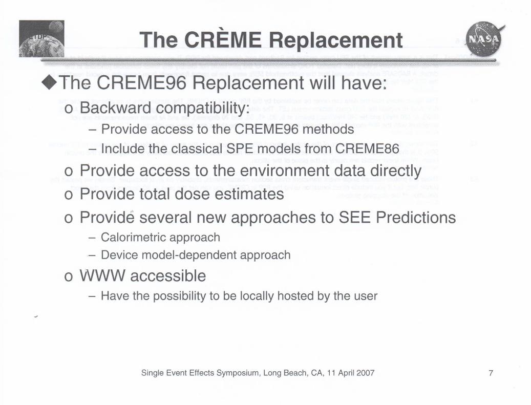
"The CREME Replacement
+The CREME96 Replacement will have:o Backward compatibility:
- Provide access to the CREME96 methods
- Include the classical SPE models from CREME86
o Provide access to the environment data directly
o Provide total dose estimates
o Provide several new approaches to SEE Predictions- Calorimetric approach
- Device model-dependent approach
o WWW accessible- Have the possibility to be locally hosted by the user
Single Event Effects Symposium, Long Beach, CA, 11 April 2007 7

Technical Team
• Marshall Space Flight Center Teamo Scientists
- James H. Adams, Subproject Lead and Cosmic Ray Team Lead at MSFC
- Nasser Barghouty, Astrophysicist, Cosmic Ray Team at MSFC
- Zi-Wei Lin, Nuclear Physicist, Research Professor at Univ. of Alabama in Huntsville
- John Watts, Cosmic Ray Physicist, Cosmic Ray Team at MSFC
• Institute for Space and Defense Electronics (ISDE), Vanderbilt Universityo Principal Engineers
- Robert A. Weller, Prof. of Electrical Engineering, Prof. of Physics
- Robert A. Reed, Research Associate Professor of Electrical Engineering
- Ronald D. Schrimpf, Prof. of Electrical Engineering, Director of ISDE
- Marcus H. Mendenhall, Research Associate Professor of Physics
o Additional Engineering Staff Participants
- Lloyd W. Massengill, Prof. of Electrical Engineering, Director of Engineering, ISDE
- Brian Sierawski, ISDE Engineer
- Kevin Warren, ISDE Senior Engineer
- Dennis Ball, ISDE Engineer
o Graduate Students
- Students from the Radiation Effects and Reliability Group test and use ISDE code
Single Event Effects Symposium, Long Beach, CA, 11 April 2007 8

Technical Objectives
+ Improve External Radiation Environment De~criptions
o Galactic cosmic rayso Solar energetic particleso Anomalous cosmic rays
+ Improve Radiation Transport though Spacecrafto Full Monte Carlo radiation transport
+ Provide a Physics-Based Simulation Tool of Single-EventEffects It
o Correctly treat hole-electron plasma creationo Charge collectiono Circuit response
+ Use the Tool to:o Diagnose SEE mechanisms in selected technologies
-' + Provide a WWW site to predict total dose and SEE effectson spacecraft
Single Event Effects Symposium, Long Beach, CA, 11 April 2007 9

Technical ApproachThe External Environment
+ Quiet-time Galactic Cosmic Ray (GCR) Environmento We will evaluate the available GCR models against data and choose the
most accurate one.
+ Solar Energetic Particle Environmentso We will offer a variety of models based on real event (probably using
Xapsos spectral fits)
o We will include a probabilistic model based on the work of Joan Feynman
+ The Anomalous Cosmic Ray Environment in the Outer Heliosphere
Radiation Transport+ The external environment will be propagated though the spacecraft
structure to the electronic part of interest using a Monte Carlo transportcode (probably GEANT or FLUKA)o These codes include the capability to calculate the absorbed dose in the
part of interest (thus allowing the total dose to be predicted)
Single Event Effects Symposium, Long Beach, CA, 11 April 2007 10

RADSAFE Implementation Concept
..Radiation EnvironmentModels
Approximate__-4.....1JIo<1 Response Models.
Virtual" Irradiator
PYO~SWG ..
REOC++
[Geant4]~ )
LVi~---...-
..Energy
Deposition&
Partitioning
1---.:1 Q(r, t) ~;''''I Poisson +---I:~ DesignSolver Decision
TCADGeometry
Single Event Effects Symposium, Long Beach, CA, 11 April 2007 11

Description of RADSAFE
• RADSAFE will extend CREME96 modelso Leverages ongoing NASA/DoD funded development at Vande'rbilt University
• RHESE support will bring key portions of the RADSAFE concept to NASAengineers through the CREME-MC, a world wide web tool
• Examples of new on-orbit prediction capabilitieso Heavy ion nuclear reactionso Realistic geometries associated with modern technologieso Improved charge collection modelso Multiple Bit Upsets (i.e. FPGA based memory)o Proton induced effects in modern technologies
• Extensible to capture new, technology based models
DesignDecision
PoissonSolver
Q(r,t)
reADGeometry
EnergyDeposition
&Partitioning
Radiation Environments 1----+-1 Response Models.------l (CREME96) (CREME96)
RHESE RHESE
Single Event Effects Symposium, Long Beach, CA, 11 April 2007 12

SEE Rate Predictions using RADSAFE
Statistical CircuitResponse
Predictable System Error Rates
~
Trackable System EffectsFunctional Errors
ComponentResponseStatistics
Physics of RadiationInteraction
Single Event Effects Symposium, Long Beach, CA, 11 April 2007 13

Structure of MRED - Core of RHESE Tool
• MRED8: a Python/Geant4 application• Core: c++ for speed• Interface: SWIG (simplified
wrapper interface generator)• Python: THe language for
software system integration• Target machine is a Linux
cluster with 1k x86 and ppc nodes
Python
SWIG
MREDC++
( Geant4 )
Single Event Effects Symposium, Long Beach, CA, 11 April 2007 14

Modeling a Complex Stack - Nuclear Events
~7 __~:-Y;)~ 2x2x2 IJm3
• "\\h " SensitiveVolume
I
Si021.0 IJm
Si-Nitride 0.4 m
High energy secondary particlescreated by nuclear reactions
with W in the Ie overlayer
4------ 50 IJm
2520
- Ne523 MeV- Ne 523 MeV - W plug
10 15
Energy (MeV)
Nuclear Reition Fragments
5
...............LET
I Direct I
• EX9.mple: MRED used to predict SE effects for twostructures:
o Stylized stack to approximate an Ie overlayer withand without W
• Direct and Indirect reactions computed• Energy deposition events included from primary and
secondary particles
(/) 106.....c::
105a.>>
W 104"t-o
103L-
a.>.0
102E:::J
101Za.>
10°>~('0
10-1a.>
0:: 10-2
J
Single Event Effects Symposium, Long Beach, CA, 11 April 2007 15

25
/1.0
2010 15Energy (MeV)
• CREME96• Si only: MRED• Si withW layer: MRED
Solar MinimumZ = 1 to 92
Charge (pC)0.5
5
Product Application Example:Using MRED to Predict SEE Rates
......................................:t .
IMSOffice2! -\................. - - - - ~~.. ·k···················-···-·1O~12
10~13 L..-.-l...---'-...l--.I..--'----'----J'---'---'---'--"'il~___...---L...-.....L-'----'-___L......f.J.t___l_--'-----'----'---J
o
Single Event Effects Symposium, Long Beach, CA, 11 April 2007 16

Slide 16
MSOffice2 This is a plot of energy deposition rate in a 10 by 10 by 1 micron volume within a block of silicon from the GCR envionment. Theblue case is pure silicon and the red case is with a tungsten layer above the sensitive volume.
1 8/ 6/2006

Summary
+ Single Event Effect (SEE) rate predictions with current models areunreliable for modern devices because: I
- Existing SEE prediction tools do not include effects found in m_oderndevices
- Accelerator tests cannot be intepreted by traditional methods toprovide accurate SEE predictions with existing tools.
+ We will use available physics-based device modeling to diagnose thecauses of SEEs in selected devices.
+ We will provide a WWW-based computational tool that:o supports real-time prediction of component reliability.o Includes improved environmental models that are availableo Uses available Monte Carlo radiation transport codeso Uses calorimetric methods informed by physics-based charge collection
and circuit response codes
+ This tool will provide:o Estimates of mission-specific total dose and SEE rateso To enable the design of safe reliable space electronics.
Single Event Effects Symposium, Long Beach, CA, 11 April 2007 17