creo® ui editor - ptcsupport.ptc.com/wcms/files/162724/en/creo3_m110_ui_editor_c_user.pdfcreated...
TRANSCRIPT

Creo® UI EditorC++ User’s GuideDatecode M110


Copyright © 2016 PTC Inc. and/or Its Subsidiary Companies. All Rights Reserved.
User and training guides and related documentation from PTC Inc. and its subsidiary companies (collectively"PTC") are subject to the copyright laws of the United States and other countries and are provided under alicense agreement that restricts copying, disclosure, and use of such documentation. PTC hereby grants to thelicensed software user the right to make copies in printed form of this documentation if provided on softwaremedia, but only for internal/personal use and in accordance with the license agreement under which theapplicable software is licensed. Any copy made shall include the PTC copyright notice and any otherproprietary notice provided by PTC. Training materials may not be copied without the express written consentof PTC. This documentation may not be disclosed, transferred, modified, or reduced to any form, includingelectronic media, or transmitted or made publicly available by any means without the prior written consent ofPTC and no authorization is granted to make copies for such purposes. Information described herein isfurnished for general information only, is subject to change without notice, and should not be construed as awarranty or commitment by PTC. PTC assumes no responsibility or liability for any errors or inaccuraciesthat may appear in this document.
The software described in this document is provided under written license agreement, contains valuable tradesecrets and proprietary information, and is protected by the copyright laws of the United States and othercountries. It may not be copied or distributed in any form or medium, disclosed to third parties, or used in anymanner not provided for in the software licenses agreement except with written prior approval from PTC.
UNAUTHORIZED USE OF SOFTWARE OR ITS DOCUMENTATION CAN RESULT IN CIVILDAMAGES AND CRIMINAL PROSECUTION.
PTC regards software piracy as the crime it is, and we view offenders accordingly. We do not tolerate thepiracy of PTC software products, and we pursue (both civilly and criminally) those who do so using all legalmeans available, including public and private surveillance resources. As part of these efforts, PTC uses datamonitoring and scouring technologies to obtain and transmit data on users of illegal copies of our software.This data collection is not performed on users of legally licensed software from PTC and its authorizeddistributors. If you are using an illegal copy of our software and do not consent to the collection andtransmission of such data (including to the United States), cease using the illegal version, and contact PTC toobtain a legally licensed copy.
Important Copyright, Trademark, Patent, and Licensing Information: See the About Box, or copyrightnotice, of your PTC software.
UNITED STATES GOVERNMENT RIGHTS
PTC software products and software documentation are “commercial items” as that term is defined at 48 C.F.R. 2.101. Pursuant to Federal Acquisition Regulation (FAR) 12.212 (a)-(b) (Computer Software) (MAY 2014)for civilian agencies or the Defense Federal Acquisition Regulation Supplement (DFARS) at 227.7202-1(a)(Policy) and 227.7202-3 (a) (Rights in commercial computer software or commercial computer softwaredocumentation) (FEB 2014) for the Department of Defense, PTC software products and softwaredocumentation are provided to the U.S. Government under the PTC commercial license agreement. Use,duplication or disclosure by the U.S. Government is subject solely to the terms and conditions set forth in theapplicable PTC software license agreement.
PTC Inc., 140 Kendrick Street, Needham, MA 02494 USA


Contents
Creo UI Foundation Classes Introduction ......................................................................7Overview..............................................................................................................8Basic Concepts ....................................................................................................8
User Interface Basics ................................................................................................17About the Creo UI Editor Main Window.................................................................18Menu Bar ...........................................................................................................18Creating a New Dialog Box..................................................................................23Adding Components to the Dialog Box .................................................................23Opening and Closing the Dialog Box ....................................................................23Saving the Dialog Box.........................................................................................24Saving a Copy of the Dialog Box ..........................................................................24Saving the Code File...........................................................................................25To Edit Properties of a Component or dialog box ...................................................25
Grid..........................................................................................................................27Grid Positioning Scheme.....................................................................................28
User Interface: Dialogs ..............................................................................................33Label .................................................................................................................34PushButton ........................................................................................................36CheckButton ......................................................................................................38RadioGroup .......................................................................................................42InputPanel .........................................................................................................45TextArea ............................................................................................................49List ....................................................................................................................50OptionMenu .......................................................................................................55Layout ...............................................................................................................58Tab ....................................................................................................................60CascadeButton...................................................................................................62SpinBox .............................................................................................................64ScrollBar ............................................................................................................67Slider .................................................................................................................70ProgressBar .......................................................................................................72DrawingArea ......................................................................................................73Table .................................................................................................................74NakedWindow....................................................................................................75Tree...................................................................................................................76MenuBar ............................................................................................................78MenuPane .........................................................................................................79Dialogs ..............................................................................................................80
5

Basic Concepts of the Creo UI Editor Components ......................................................81Displaying Text Caption for Components ..............................................................82Defining the Alignment of the Text Caption............................................................82Defining a Mnemonic for Components..................................................................82Defining an Accelerator Hot Key ..........................................................................83Defining an Image for Components ......................................................................83Defining the Alignment Between the Image and Text Caption .................................83Creating Name and Label Pairs ...........................................................................84Defining the Width of a Component ......................................................................85Defining the Mouse Pointers................................................................................85Defining the Color ...............................................................................................86Setting the Help Text ...........................................................................................86Defining the Visibility of a Component ..................................................................87Defining the Availability of a Component...............................................................87Defining the Type of Selection .............................................................................87
6 Creo® UI Editor

1Creo UI Foundation Classes
IntroductionOverview ....................................................................................................................8Basic Concepts ...........................................................................................................8
This chapter provides an introduction to the basic concepts of the Creo UIFoundation classes.
7

OverviewThe User Interface Foundation Classes (UIFC) provides a framework for creating,displaying and managing additions to the Creo user interface. New dialogs can becreated using the Creo UI Editor, and then loaded into a Creo session. The UIFCis a platform and operating system independent toolkit, supporting trail files,mapkeys and a common appearance to the rest of the Creo user interface.
Basic ConceptsThis sections provides more information on the basic concepts used in Creo UIEditor.
DialogsA dialog is the term used for all top-level windows by the UIFC. This includesanything from a Creo main window to an exit confirmation dialog box.
ModalityDialogs can be defined to be either modal, also referred to as blocking ormodeless. When the Activate function is called for a given dialog, modal dialogsprevent access to other individual dialogs or the whole application, whereasmodeless dialogs allow the user to interact with the rest of the application as wellas the modeless dialog itself.In the activated state, modal dialogs start an event loop and process events and thefunction uifcActivateDialog() will only return when the dialog is exitedfrom a callback function. Modeless dialogs on the other hand do not start an eventloop so the call to activate the dialog returns immediately. Event processing formodeless dialogs is handled by the currently active event loop.
Dialog LifecycleThe dialog lifecycle has 4 or 5 stages depending on whether it is modeless ormodal. The steps to display a dialog are:
1. CreateCall the function uifcCreateDialog() to create an instance of a dialog froma resource file. For example:uifcCreateDialog (“MyDialogInstance”,
“my_dialog_resource_file”);
8 Creo® UI Editor

Creating the dialog only loads the definition into memory; it does not show thedialog on the screen, which happens later.
2. InitializeOnce the dialog has been created, for example by loading a resource file, you canthen set up run time values for the dialog or components within the dialog. Forexample, if the dialog relates to editing a file, you might want to set the title of thedialog to the name of the file. We recommend that you set the title and modifyover components before the dialog is displayed on the screen as the values on thecomponents can affect the overall size of the dialog and relative placement ofcomponents in the dialog. This avoids causing the dialog to resize, or cause visualdisturbance, to the user due to the content in the dialog changing.Also at this point you will need to setup the action listeners for the components inthe dialog. For more information, see the section on Event processing on page 10.
3. ActivateActivate the dialog, that is, show the dialog on the screen by calling the functionuifcActivateDialog():uifcActivateDialog (“MyDialogInstance”);
If the dialog type is modal, this call will start a new event loop. The call will notreturn until the dialog exits from the event loop. Refer to the section 4. Exit onpage 9.For a modeless dialog, the activate call will display the dialog and returnimmediately.
4. ExitA modal dialog stays in the uifcActivateDialog() call and has an eventloop running while it is displayed. You need to exit the event loop, to dismiss thedialog. This can be done from an action listener by calling:uifcExitDialog (“MyDialogInstance”, status);
Specify the name of the dialog instance and an integer status value as thearguments to the call to uifcExitDialog(). The status value is used as thereturn status from the uifcActivateDialog() call. Note that you must exitthe event loop for a modal dialog before it can be destroyed.
Creo UI Foundation Classes Introduction 9

NoteExiting the event loop for a dialog does not remove the dialog from the screen.It will still be displayed, and it is possible to activate the dialog again and starta new event loop.
For modeless dialogs, which do not have any associated event loop, there is noneed to call the exit function.
5. DestroyTo finally remove the dialog from the screen after any event loop associated withthe dialog has been exited, call:uifcDestroyDialog (“my dialog instance”);
For modal dialogs this will normally be called immediately after the call touifcActivateDialog().At this point the dialog will need to be created again before it can be reused.
Event processingOnce you have your dialog displayed on the screen, you need to be able torespond to the user interacting with it. This is done by the use of action listenerson the dialog and on the components within it.Create an action listener by deriving a new class from the appropriate ObjectTOOLKIT Listener base class for the given component type. The followingexample shows you how to define an action listener for a PushButton component:class MyButtonListener : public uifcDefaultPushButtonListener
{
MyButtonListener() {};
~MyButtonListener() {};
OnActivate (uifcPushButton_ptr component);
};
uifcPushButton_ptr ok_button = uifcPushButtonFind("MyDialogInstance",
"ok_button");
MyButtonListner* ok_listner = new MyButtonListner();
Ok_button->AddActionListener (ok_listner);
10 Creo® UI Editor

In this example, the OnActivate() method is overridden, which informs youwhen the user has activated the PushButton, that is, when the user has clicked onthe component, or pressed the spacebar when the keyboard focus was on thecomponent, or if the activate action was programmatically pushed from code. Asyou are defining your own class for the notification, you are free to include yourown methods and data in the class, which allow for more versatility in associatingyour own data with the component.
NoteCertain action types are not recorded to trail files unless there is a method thathad been derived for them from the base class. If you were to override all thenotification methods in the Listener class, for example to have a generalpurpose class for all your components, then you may cause additionalunwanted actions to be recorded into the output trail file. It is recommendedthat you only override those notifications that you need for a given individualcomponent.
Text DisplayText displayed to the user in components can be either simple Unicode strings or asubset of HTML tags to control text attributes like the use of bold, italics, fontsize, and so on.
ImagesThe supported image formats are PNG, Jpeg, GIF, BMP, and ICO. If using animage to define a cursor it is recommended that you use an ICO file, to allow thedefinition of the cursor hotspot.
Component PositioningThe primary way to position components is via a Grid structure. Grids allowautomatic relative placement of components and resizing of a component if thecomponent is a child of a Dialog or Layout. Alternatively, components can bepositioned and resized manually when the component is a child of a DrawingArea,NakedWindow or PGLWindow. Component classes such as the Sash, Tab, orTable component define their own placement schemes for their child components.
Creo UI Foundation Classes Introduction 11

GridThe Layout and Dialog components both use a grid based positioning scheme fortheir child components. This consists of a recursive rectangular grid of cellssimilar to an HTML table or a spreadsheet. Each cell in the grid can either beempty or can contain a component or a nested sub-grid.A grid cell has offset values in pixels for the top, bottom, left and right sides,which give the spacing between a component in the cell and the cell edges. Youcan also define attachments for the cell content, so that a component can have it’sleft, right, top or bottom edges fixed to the corresponding cell edge taking intoaccount any offset defined for the edge, in any combination.If you attach a component to only the left or right side, or the top or bottom of agrid cell, then the component will stick to that edge if the grid cell changes size orposition. Attaching a component to both the left and right sides or both the top andbottom edges will cause the component to stretch to be the size of the grid cell,less any offsets in that direction.A row or column in a grid can be defined as being either resizable or non-resizable. This controls the distribution of any size changes made to the Dialog orLayout component, so that the change in size in the horizontal or vertical directionis divided up between the row and columns that are marked as being resizable. Atleast one of the rows and one of the columns must be resizable in order to acceptany size changes.
Button SizesBy default, a toggle style PushButton in a dialog that is not in a menu and has noattachments will have the same width, based on the widest toggle stylePushButton component in the dialog. You can explicitly control this behavior byusing the UseStandardWidth attribute. When set to TRUE, the componentwill have the standard width behavior regardless of any attachments.
NoteWhen determining the widest component, the ‘natural’ size of the componentis used, that is the size of the component before it is potentially stretched byany attachments.
You can also set CascadeButton and CheckButton components to have thestandard width behavior by setting the UseStandardWidth attribute to TRUE.
12 Creo® UI Editor

InternationalizationWhere possible you should define your dialogs using resource files rather thancreating the dialogs and components in code. The strings defined in the resourcefile that are displayed on the user interface can be automatically extracted andused to create a translation file. Separate translation files can then be created foreach supported language so that at run time the appropriately localized text istaken from the translation file.
NoteBy default, the resource files contain English text strings, if any translationsare missing, then displayed test will fallback to the English text in the resourcefile.
Textual input component such as the TextArea, InputPanel, and so on supportinput methods and right to left input.
Trail Files and MapkeysActions such as the user clicking on a PushButton or selecting an item in a Listcomponent are automatically written into the output trail file for the session. Forsimple actions such as activating a PushButton, only the action type and the dialogand component names are recorded in the trail files. For more complex actions,such as selecting an item in a List, Table, OptionMenu, or RadioGroup, along withthe action type and component name, the names of the items that were selected arealso recorded in the trail file.Having meaningful names for components and particularly in the case of thenames of items in the component, will be helpful while examining trail files, forexample, ok_button rather than PushButton3.In the case of items in a List, where the content might change from session tosession, such as a list of file names, you should base the names on a scheme thatwill be as far as possible invariant between times that the dialog is displayed. Forexample, if you use a numeric index for the item names, then this reduces thereadability of the resulting trail file entries and will most likely prevent anymapkeys that use the component from working in another situation other thanwhen the set of items in the component are exactly identical. Further more, if atsome later point in time you add more items into the component, then a simpleindex will mean that the names written in an earlier trail file or mapkey will nolonger map to the correct items. If however you used an invariant name, themapping will be unaffected and trail files and mapkeys will still work.
Creo UI Foundation Classes Introduction 13

Accelerators and MnemonicsAccelerators and mnemonics are two different ways of controlling components viathe keyboard.
MnemonicsMnemonics are shown as an underlined character in the label text of a component,using Alt + the underlined character will activate the component. The mnemonicis defined by putting an ampersand character in the label text of the componentimmediately in front of the character to be used, for example &File. To display aliteral ampersand character you need to use two ampersands, for example This&& that.In the case of a PushButton or CheckButton component the mnemonic behaves asif the user clicked on the component. In the case of a Label or Layout componentthis will move the keyboard focus onto the component defined by the Focusattribute. In the case of a MenuBar component it will open the menu with thematching mnemonic and similarly for a CascadeButton it will open it’s menu.Mnemonics are only available to the user to use if they are shown in the currentlyactive dialog, that is the dialog with the keyboard focus. The component with themnemonic also needs to be visible. If duplicate mnemonics are used in the dialogfor PushButton or CheckButton, then rather than immediately activating thecomponent, the keyboard focus is cycled between the components with the samematching mnemonic, to allow the user to chose and activate using the spacebar.
NoteA best practice is to avoid having duplicate mnemonics as far as possible.
It is good practice to add mnemonics to all the components in a menu, as thisallows the user to directly active a button in the menu by typing the sequence ofkey presses, rather than having to navigate through the menu using the arrowkeys.
NoteWhen a menu pane is open, pressing the mnemonic character key will activatethe mnemonic, the Alt key is not required. Also when the menu is open thescope of any mnemonics available to the user is limited to just those in themenu itself.
14 Creo® UI Editor

AcceleratorsUnlike mnemonics, accelerators can be used on components that are notimmediately visible in the dialog, that is, an accelerator can activate componentsthat are in a menu such as a popup menu or a menu associated with aCascadeButton or MenuBar without having to open the menu.Define an accelerator for a component using the AcceleratorCode attribute inCreo UI Editor. The accelerator consists of a character key and one or moremodifier keys, such as, Ctrl, Alt, or Shift where one of them should be the Ctrlkey. When a component with an accelerator is shown in a menu, the acceleratordefinition is automatically shown in a column on the right-hand side.For component classes that support the AcceleratorCode attribute, theaccelerator will call the Activate action on the component. The Dialog class is anexception to this, where the accelerator will call the Close action on the dialog,that is, using the accelerator will be similar to clicking the Close button on thedialog. It is a good practice to define an accelerator using the ‘Escape’ key ondialogs that contain transient content or short tasks, for example, prompts, queriesor perhaps something like renaming an object. This allows the user to quickly getout of the dialog and should behave as though the task was cancelled.
Creo UI Foundation Classes Introduction 15

2User Interface Basics
About the Creo UI Editor Main Window .......................................................................18Menu Bar..................................................................................................................18Creating a New Dialog Box ........................................................................................23Adding Components to the Dialog Box ........................................................................23Opening and Closing the Dialog Box...........................................................................23Saving the Dialog Box................................................................................................24Saving a Copy of the Dialog Box.................................................................................24Saving the Code File .................................................................................................25To Edit Properties of a Component or dialog box..........................................................25
This chapter describes the user interface for the Creo UI Editor in detail.
17

About the Creo UI Editor Main WindowYou can create dialog boxes using the Creo UI Editor. The dialog boxes are savedas resource files. Each dialog box that you create appears in the same Creo UIEditor window.The Creo UI Editor user interface consists of the following elements:• Menu Bar• Quick Access toolbar• Tree• Work Area• Status BarThe following figure shows the various elements of the Creo UI Editor:
1 Menu bar2 Quick Access toolbar3 Tree4 Work Area5 Status bar
Menu BarThe menu bar contains commands for creating, saving, and modifying dialogboxes and components, and for setting your Creo UI Editor environment. Itcontains the following menus:• File• Edit• Tree
18 Creo® UI Editor

• View• Help
About the File MenuThe File menu allows you to create a new dialog box or work with an existingdialog box.It has the following commands:
Command Name Icon on Quick AccessToolbar
Description
New Creates a new dialog box.
Open Opens an existing dialogbox.
Close Closes the current dialogbox.
Save Saves the dialog box.Save As Saves a copy of the dialog
box as a resource file(.res).
Save Code Saves the source code tocontrol the dialog boxprogrammatically.
Exit Exits the Creo UI Editor.
About the Edit MenuThe Edit menu contains commands that allow you to cut, paste, delete and renamethe selected components in a dialog box. You can select and manipulate thecomponents in the dialog box using the Edit menu.It has the following commands:
Command Name Icon on Quick AccessToolbar
Description
Cut Copies the selectedcomponent to theclipboard and then deletesthe selected component.
Copy Copies the selectedcomponent to theclipboard withoutremoving it from itsoriginal location.
User Interface Basics 19

Command Name Icon on Quick AccessToolbar
Description
Paste Pastes the cut or copiedcomponent to the selectedcell in the grid.
Delete Removes the selectedcomponent or a layout ofcomponents.
Rename Changes the name of theselected component.
Properties Edits the properties of theselected component or thedialog box.
About the Tools Menu
About the View MenuThe View menu allows you to customize the display of the Creo UI Editor. Itprovides options to control the display of different types of grid in the work areaand display of user interface components in the Creo UI Editor.It has the following commands:
Command Name Icon on Quick AccessToolbar
Description
No Grid No grid is displayed inthe work area.
Grid Displays the placementgrid in the work areaaround the components.The placement grid helpsyou to position thecomponents in a dialogbox.
Resource Grid Displays the resource gridin the work area aroundthe components. Theresource grid is the gridstructure present withinthe component.
Both Displays both theplacement and resourcegrids in the work area
20 Creo® UI Editor

Command Name Icon on Quick AccessToolbar
Description
around the components.Refresh Refreshes the work area
in the Creo UI Editor.You can also use thefunction key F5 to refreshthe work area.
Preview Enables you to previewthe current dialog box.The preview isdynamically updated asyou modify the dialogbox.
Toolbar Displays the QuickAccess toolbar.The Quick Access toolbaris located at the top of theCreo UI Editor. Itprovides quick access tofrequently usedcommands, such as Open,Close and Save files,copy and pastecomponents, and so on.
Status Bar Displays the status bar.The status bar is locatedat the bottom of the CreoUI Editor. It displays thename of the commandselected in the QuickAccess toolbar. It alsodisplays additionalinformation about thecommand selected fromthe menu bar.
Clipboard Displays the Clipboard.The Clipboard stores thecopied component.
User Interface Basics 21

About the Tree MenuThe Tree menu allows you to expand and collapse the tree structure of the dialogbox. Each branch of the tree corresponds to either individual components orparent container components that hold the child components. You can expand orcollapse the tree on a branch level or on an individual layout level. When thismenu is selected, the commands described below appear.
Command Name DescriptionExpand One Level Expands the selected dialog or a branch
by one level. It displays the immediatechildren of the selected branch.
Expand Branch Expands the selected dialog box or abranch in the component tree. It displaysthe node and sub-nodes of the selectedbranch.
Expand All Expands all the branches of thecomponent tree.
Collapse Branch Collapses the expanded dialog or thebranches in the component tree. Itcollapses all the nodes and sub-nodes ofselected tree branch.
About the Help MenuThe Help menu allows you to see the context-sensitive help and the releaseinformation.It has the following commands:
Command Name Icon on Quick AccessToolbar
Description
About Creo UI Editor Displays the copyrightand release informationfor Creo UI Editor.
What’s This Displays the context-sensitive help for theselected command.Click What’s Thiscommand, and then clicktree, work area, or on theicon for which you wanthelp. Creo UI Editordisplays the context-sensitive help.
22 Creo® UI Editor

Creating a New Dialog BoxTo create a new dialog box, click File ▶▶ New or click on the Quick Accesstoolbar.The work area consists of a single grid cell and the tree area displays the name ofdialog box as the parent node. Select components from the Quick Access toolbarand add them to the dialog box. These components appear as child nodes of theparent node in the tree.Click Save. The dialog box is saved as a resource file with the same name as thatof the parent node in the tree.
NoteYou cannot save the resource file if you do not add components in it.
Refer to section Adding Components to the Dialog Box on page 23, for moreinformation on adding components.
Adding Components to the Dialog BoxTo add components:1. Click the component from the Quick Access toolbar.2. Place the component in a single grid cell in the work area. You can add
additional components as required to create the dialog box. Place theadditional components in empty grid cells.
Opening and Closing the Dialog BoxYou work with resource files when you open a dialog box and edit it.
1. Click File ▶▶ Open or click on the Quick Access toolbar. The Open Filedialog box opens. The directory in the address bar defaults to one of thefollowing items:• The directory in which Creo UI Editor has been installed.• The directory you last accessed to open, save, or save a copy of your file.
2. Locate the file to open in the default directory or select a different directoryusing a method below:• Click a folder under Common Folders.• Click any directory in the address bar and then select another directory or a
file. The path in the address bar changes as you select directories.
User Interface Basics 23

• Click the arrow in the address bar to toggle it to display the directory path.You can directly edit the path to the required directory.
• Click Folder Tree and select a folder to browse.3. To open the resource file, double-click it or click OK. The dialog box along
with its components appears in the work area.
To close the dialog box, click File ▶▶ Close or click on the Quick Accesstoolbar.
Saving the Dialog BoxTo save a resource file, click File ▶▶ Save or click on the Quick Access toolbar.The file is saved with the same name as displayed in the parent node of the tree.To change the name of the dialog box before saving it:1. Right-click the dialog box in the tree or click Edit ▶▶ Properties. The Properties
dialog box appears.2. Click Change.3. In the Name box, type the new name for the new dialog box.4. Click OK.5. To save the dialog box, click File ▶▶ Save.
NoteIf you rename an existing dialog box and save the file, it is saved as a copy ofthe original file with the new name.
Saving a Copy of the Dialog BoxTo save a copy of the dialog box:
1. Click File ▶▶ Save As or click on the Quick Access toolbar. The Save Asdialog box opens. The directory in the address bar defaults to one of thefollowing items:• The directory in which Creo UI Editor has been installed.• The directory you last accessed to open, save, or save a copy of your file.
2. You can accept the default directory or browse to a new directory.3. In the File Name box, type a different name for the resource file.4. Click OK in the Save As dialog box. The dialog box is saved as a resource file.
24 Creo® UI Editor

Saving the Code FileOnce you create a dialog box using the Creo UI Editor, you can automaticallygenerate the C++ code files using the Save Code command. This code can invokethe resource file to invoke the dialog box at runtime.
1. Click File ▶▶ Save Code or click on the Quick Access toolbar. The SaveCode dialog box opens.
2. In the Options tab, select main window to open the dialog box as the mainwindow of the application, else select secondary window to open the dialogbox as the secondary window of the application.
3. In the Actions tab, specify the following:• Classes—Select the component class.• Used—Move the actions that are valid for the component class from the
Unused list to the Used list. Click >> or << to move the actions across lists.4. Click OK. The code is saved as a .c file.
To Edit Properties of a Component ordialog boxTo edit the properties of a component or a dialog box:1. Select the component or dialog box.2. Click Edit ▶▶ Properties or right click on the selected component in the
component tree and click Properties from the shortcut menu. Alternatively,click on the Quick Access toolbar. The Properties dialog box opens.
3. The following is the list of properties that you can view and edit:• The Name box displays the name of the component or dialog box. Click
Change to modify the name.• The Type box displays the type of the selected component. You cannot
modify this field.• In the Component tab, select an attribute and set or modify its value.• Click the Grid tab to modify the grid parameters.• Click the Navigation tab to specify the navigation options for the selected
component within the dialog.4. Click OK to save and close the Properties dialog box.
User Interface Basics 25


3Grid
Grid Positioning Scheme............................................................................................28
The work area of the Creo UI Editor contains a Grid representation. This chapterprovides more details on using the Grid.
27

Grid Positioning SchemeThe Layout and Dialog components use a grid based component placementscheme. This uses a rectangular grid of cells, which can be thought of like aspreadsheet, where the cell can be either blank or contain a single component.
ResizingThe grid supports resizing either from the user resizing the dialog or also due tothe component themselves changing size. Component resizing can result due toone of the following:• Run-time changes made to a component, such as changing a label.• When the application is run, circumstances such as text or fonts available on
the computer could cause the components to have a different size to that whenthe dialog was created.
You can mark the rows and columns of a grid as being resizable or non-resizable.This allows you to construct a grid of different components, so that a componentclass such as a TextArea can be made resizable allowing it to make use of anyextra space or can shrink down if less space is available while component such asPushButtons, that should not be resized, can stay the same size.For example, consider a simple information dialog that shows some text in aTextArea at the top and two PushButton components at the bottom inside a Layoutcomponent:
In the above example, the Dialog has a grid consisting of one column with tworows, that is two cells, with the TextArea component in the top cell and the Layoutcomponent in the bottom cell. In the Layout component there is a grid consistingof one row and two columns, with the Clear button in the left cell and the Savebutton in the right cell.
28 Creo® UI Editor

If you make the dialog larger, and all the grid rows and columns are resizable,then the dialog will appear as follows:
From the image, you can see the extra space available to the dialog is distributedequally between the TextArea component and the PushButton components, whichleads to an unwanted change in the amount of space around the PushButtons.Now if you make the bottom row of the grid in the Dialog component to be non-resizable, so the PushButton components are not resizable vertically, then thedialog will appear as follows:
NoteThe ability to resize is an attribute of the grid rows and columns, and not ofindividual grid cells. Thus if a row is made resizable or non-resizable, then allthe cells in that row would be either resizable or non-resizable in the verticaldirection, and similarly for a column affecting the resizing of a cellhorizontally.
Additionally, at least one row and one column in the grid must be resizable, toallow for any change in size. This means that if the grid in the component has onlyone row or column, then that row or column must be resizable.
AttachmentsA component in a grid cell also has four attributes that describe how thecomponent is attached to the each of the edges of the cell, namely the top, bottom,left, and right attachments.
Grid 29

Depending on how the attachments are set, the component will be stretchedhorizontally and vertically, or be moved in response to the grid cell changing size.If the component has both left and right attachments, then component in grid cellwill be stretched horizontally to take up the full width of the cell. Similarly if thecomponent is attached to both the top and bottom of the grid, it will be stretchedvertically. If the component has no horizontal attachments set, then it will bepositioned in the middle of the available width in the cell, and again similarly forthe vertical attachments. If the component has a single horizontal or verticalattachment, for example to the left but not to the right or top or bottom, then thecomponent will be aligned against the attached edge.
In the above image the Save button is now attached to the right-hand side, and theClear button also attached on the right-hand side. The Save button is in a non-resizable column, with the Clear button in a resizable column.
NoteIndividual component classes have their own default values for attachments.Refer to the documentation for the component classes to see what these are.
OffsetsIn the same way that the component has attachments to the edges of its grid cell,there are also offsets that can be set on the top, bottom, left and right edges of thecell and the component. The offsets are between the component and the cell it isin, not between adjacent components, so the right offset of one component and theleft offset of another component are added together to give the minimum spacing
30 Creo® UI Editor

between the components that are next to each other horizontally. In addition to theoffset values, the spacing between components will depend on the attachments onthe component and whether the cell might have been resized to be larger.
In the above image offsets have been added around the components to give a lesscluttered appearance.
Grid 31


4User Interface: Dialogs
Label ........................................................................................................................34PushButton...............................................................................................................36CheckButton .............................................................................................................38RadioGroup ..............................................................................................................42InputPanel ................................................................................................................45TextArea...................................................................................................................49List ...........................................................................................................................50OptionMenu..............................................................................................................55Layout ......................................................................................................................58Tab...........................................................................................................................60CascadeButton .........................................................................................................62SpinBox....................................................................................................................64ScrollBar...................................................................................................................67Slider........................................................................................................................70ProgressBar..............................................................................................................72DrawingArea.............................................................................................................73Table ........................................................................................................................74NakedWindow...........................................................................................................75Tree .........................................................................................................................76MenuBar...................................................................................................................78MenuPane ................................................................................................................79Dialogs .....................................................................................................................80
This chapter describes the User Interface components and their attributes.
33
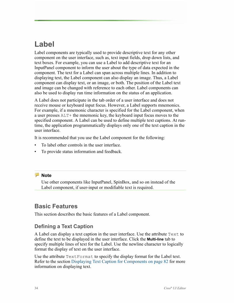
LabelLabel components are typically used to provide descriptive text for any othercomponent on the user interface, such as, text input fields, drop down lists, andtext boxes. For example, you can use a Label to add descriptive text for anInputPanel component to inform the user about the type of data expected in thecomponent. The text for a Label can span across multiple lines. In addition todisplaying text, the Label component can also display an image. Thus, a Labelcomponent can display text, or an image, or both. The position of the Label textand image can be changed with reference to each other. Label components canalso be used to display run time information on the status of an application.A Label does not participate in the tab order of a user interface and does notreceive mouse or keyboard input focus. However, a Label supports mnemonics.For example, if a mnemonic character is specified for the Label component, whena user presses ALT+ the mnemonic key, the keyboard input focus moves to thespecified component. A Label can be used to define multiple text captions. At run-time, the application programmatically displays only one of the text caption in theuser interface.It is recommended that you use the Label component for the following:• To label other controls in the user interface.• To provide status information and feedback.
NoteUse other components like InputPanel, SpinBox, and so on instead of theLabel component, if user-input or modifiable text is required.
Basic FeaturesThis section describes the basic features of a Label component.
Defining a Text CaptionA Label can display a text caption in the user interface. Use the attribute Text todefine the text to be displayed in the user interface. Click the Multi-line tab tospecify multiple lines of text for the Label. Use the newline character to logicallyformat the display of text on the user interface.Use the attribute TextFormat to specify the display format for the Label text.Refer to the section Displaying Text Caption for Components on page 82 for moreinformation on displaying text.
34 Creo® UI Editor

Defining a MnemonicThe text of a Label can be defined to have a mnemonic character. The Label itselfnever receives the keyboard input focus. The keyboard focus shifts to thecomponent specified in the attribute FocusComponentName when ALT+ themnemonic key combination is pressed. You can specify a Label with a mnemonickey defined to move focus on an InputPanel, PushButton, and so on.For example, if you specify the Text attribute as &Whats New and theFocusComponentName attribute as my_component, the keyboard input focusmoves to the component called my_component when ALT+W is pressed. Refer tothe section Defining a Mnemonic for Components on page 82 for moreinformation on mnemonics.
Defining an ImageThe Label component can display an image in the user interface. Use the attributeTitleImage to specify the image to be displayed in the Label. Specify the nameof the image with its extension, for example, my_image.png. Refer to thesection Defining an Image for Components on page 83, for more information ondefining images.Use the attribute ContentArrangement to define the placement of image andLabel text in reference to each other. Refer to the section Defining the AlignmentBetween the Image and Text Caption on page 83, for more information onaligning images.
Displaying Status InformationA Label can be used to give status information and feedback. The status istypically given at the bottom of the main window of an application. When theLabel is used for this purpose it is recommended to set the attribute Border toTrue. This attribute defines a decorated border around the Label, thus changing theappearance of the Label to befit a status-bar.
Defining Multiple Text CaptionsA Label can be used to define multiple text captions. At run-time, the applicationcode selects one of text options and displays it in the user interface. This isanalogous to having multiple Label objects on top of each, occupying the samespace, while only one Label object is visible to the user. For this, you must createmultiple pairs of objects names and object text. The ItemTextArray attributealong with the ItemNameArray attribute allows you to create a customizablelist of paired values. Refer to the section Creating Name and Label Pairs on page84, for more information on paired values.
User Interface: Dialogs 35

Every object text, that is, text caption is defined by an object name. The objectname is unique for the Label component. Use the attribute ItemNameArray todefine the object name for the text caption.The attribute ItemTextArray defines a text caption that will be displayed inthe user interface for each object name. By default it is the text defined for thefirst object name which is displayed within the Label. The width of the Labelcomponent is set according to the longest string specified for theItemTextArray attribute.The set of object names is not translated. So it is recommended that the objectnames are specified such that they are impervious to changes in locale. Only theobject text, that is, the text captions are translated. The application code only dealswith the object names. This way the code is isolated from any differences in thetext arising from internationalization (i18n).The main advantages of having paired object name-object text values are:• As all the possible text captions are defined in the resource file the
internationalization (i18n) and localization (L10n) processes are simplified.The application code can select the appropriate text caption to be displayed inthe user interface regardless of the locale of the application.
• As the Label sizes itself to the length of the longest string defined for textcaption, any of the text captions displayed in the user interface does notchange the size of the control. This in turn does not affect the size of thecontrols surrounding the Label component in the user-interface
You can specify an image for each object name. Use the attributeItemImageArray to specify the set of images.At run-time the application code can use to select the name of the object whichshould be displayed in the Label.
NoteUse of ItemNameArray and ItemTextArray is mutually exclusive withrespect to the use of the Text. If you use the ItemTextArray to define theobject text for a Label, then you cannot specify a value for the Text attribute.
PushButtonPushButton components enable you to activate behaviors within the application,in the user interface.
36 Creo® UI Editor

When you press a PushButton component, its appearance and behavior change.By default, the PushButton component displays a border around its content whenit is selected. The selected and deselected states of the PushButton component arespecified by the pushed in and out appearance of the PushButton when pressed.A PushButton component can display content such as text, or image, or both. Youcan also add a PushButton component in a menu hierarchy or in a dialog box. Forexample you can add PushButton in a menubar. A PushButton can define both amnemonic and accelerator (hot key).You can also use the PushButton component to provide a hyperlink for the user tofollow by selecting the link.It is recommended that you use the PushButton component to activate a feature ofthe application.
NoteFor buttons which retain their pressed-in state and appearance until they areactivated again the next time, use the CheckButton component instead.
Basic FeaturesThis section describes the basic features of a PushButton component.
Defining a Text CaptionA PushButton can display a text caption that describes its behavior within theapplication in the user interface.You can also define a mnemonic key to set the keyboard input focus for thePushButton component. Use the attributes Text to define the text caption andspecify a mnemonic key for the PushButton component in the user interface. Usethe attribute TextFormat to specify the display format for the PushButtoncaption text. Refer to the section Displaying Text Caption for Components onpage 82 for more information on displaying text.For example, consider the key combination Alt+F as the mnemonic, which canbe used as a shortcut to toggle and change the behavior of the PushButtoncomponent. Refer to the section Defining a Mnemonic for Components on page82 for more information on mnemonics.
User Interface: Dialogs 37

Defining a Hot-KeyPushButton component can be toggled using a keyboard shortcut, that is, anaccelerator or hot key. You can define the keyboard shortcut using the attributeAcceleratorKey. For example, set Ctrl+O as the hot-key. This keyboardshortcut which can be used to toggle the control.The accelerator key combination is displayed with the PushButton in the userinterface only for PushButtons added in a menubar. Refer to the section Definingan Accelerator Hot Key on page 83 for more information on mnemonics.
Controlling the AppearanceYou can change the appearance of a PushButton component using the attributeButtonStyle. The following types of display styles are available for aPushButton:• Toggle (BUTTON_STYLE_TOGGLE)—This is the default setting. The
PushButton is rendered as a button which toggles between two states. It has aborder and a pressed in-out appearance to reflect the state. The PushButton isdisplayed in user interface with a text caption or an image, or both. The imageis defined separately using the attribute TitleImage. The relative placementof the text caption and the image is controlled using the attributeContentArrangement. You can toggle between the states of a PushButtonby pressing the space bar, when the PushButton has input focus over it.
• Flat (BUTTON_STYLE_FLAT)—The PushButton is similar to the togglebutton except that it is displayed as a button with no border to it. It is mostlyused on the toolbar of the application since it is rendered without any borders.The border is displayed when you hover the mouse over the PushButtoncomponent or the PushButton is in pressed state. The flat type of PushButtoncomponent toggles between two states. You cannot toggle between the statesof a PushButton by pressing the space bar, when the PushButton has inputfocus over it.
• Link (BUTTON_STYLE_LINK)—The Link type PushButton is rendered as abutton which enables you to position a hyper-link in the user interface. Youcan place the link using the attribute BUTTON_STYLE_LINK.
CheckButtonCheckButton components enable you to select or clear options on the application’suser interface.When you select or clear a CheckButton component, its appearance and statechange. By default, the CheckButton component displays a check mark when it isselected. The selected state is specified by the text of the CheckButton, while thecleared state must be the opposite of the selected state.
38 Creo® UI Editor

A CheckButton component can be displayed as a toggle button. SuchCheckButton components can also be used to toggle between two exactly oppositestates.A CheckButton component can display content such as text, or image, or both.You can also add a CheckButton component in a menu hierarchy or in a dialogbox.A CheckButton can define both a mnemonic and an accelerator or the hot key.It is recommended that you use the CheckButton component for the following:• To let the user make a choice over the state of a feature in the application.• Use multiple CheckButton components to display multiple choices from
which the user can select any number of options
NoteFor mutually exclusive choices, use the RadioGroup component instead of theCheckButton component.
Basic FeaturesThis section describes basic features of a CheckButton component.
Defining a Text CaptionA CheckButton can display a text caption that describes its state in the userinterface. You can also define a mnemonic key to set the keyboard input focus andtoggle the CheckButton component. Use the attributes Text to define the textcaption and specify a mnemonic key for the CheckButton component in the userinterface. Use the attribute TextFormat to specify the display format for theCheckButton caption text.Refer to the section Displaying Text Caption for Components on page 82 for moreinformation on displaying text. For example, the key combination Alt+H is themnemonic, which can be used as a shortcut to toggle the control of theCheckButton component.Refer to the section Defining a Mnemonic for Components on page 82 for moreinformation on mnemonics.
Defining an Accelerator or Hot KeyA CheckButton component can be toggled using a keyboard shortcut, that is, anaccelerator or hot key. You can define the keyboard shortcut using the attributeAcceleratorKey. For example, Ctrl+Shift+F is the keyboard shortcut
User Interface: Dialogs 39

which can be used to toggle the control. The accelerator key combination isdisplayed with the CheckButton in the user interface only for CheckButtons addedin a menubar.Refer to the section Defining an Accelerator Hot Key on page 83 for moreinformation on hot keys.
Defining the StateTypically, a CheckButton component has two states, namely, the set staterepresenting True and the unset state representing False. The attributeCheckedState enables you to set the default state of the CheckButtoncomponent on the user interface. The attribute CheckedState in set state hasits value as 1 and has its value as 0 in the unset state.Sometimes, it is necessary for the application to indicate that the featurerepresented by a CheckButton is neither set nor unset. This mixed-value status canbe achieved with a CheckButton using the attribute InMixedState.When the CheckButton is in the mixed-value state, the states of the attributeCheckedState are not considered. In such cases, if you get the value of theattribute CheckedState, an error code is returned. However, when you click onthe CheckButton component, it returns to its normal behaviour of togglingbetween the set and unset states.
Cycling Between the StatesYou can configure the CheckButton component to set the number of states itcycles through. The attribute 3State enables you to set the number of togglestates for a CheckButton component. When this attribute is set to False, theCheckButton component toggles between two states, True or False. When theattribute 3State is set to True, the CheckButton component toggles betweenthree possible states, that is, True, False, or Mixed.
Value ofCheckedState
State of Button Comments
True (Default value) Set state The button appears with acheck mark on the userinterface.
False Unset state When the user clicks onthe button, it cycles to thenext state which is theFalse state.
Mixed Mixed state On the next click, thebutton cycles to anindeterminate state, whereit is neither set nor unset.
40 Creo® UI Editor

Sometimes it is necessary to allow users to actively to choose between threestates. The third mixed state represents an indeterminate state which theapplication can use for its own purpose. The difference between the mixed statedefined in the attributes 3State and InMixedState is as follows:• With the attribute 3State it is the user who can select the indeterminate
state.• With the attribute InMixedState it is the application which displays the
indeterminate state. The user can click the CheckButton component to reset itto toggle between set and unset states.
Controlling the AppearanceYou can change the appearance of a CheckButton component using the attributeButtonStyle. The following types of display styles are available for aCheckButton:• Check (BUTTON_STYLE_CHECK)—This is the default setting. The
CheckButton is rendered in the user interface with a text caption and a check-mark to reflect the state. The CheckButton components with this appearancecan be used for the display of two states, three states, or the mixed-value state.You can toggle between the states of a CheckButton by pressing the space bar,when the CheckButton has input focus over it. When you add a CheckButtoncomponent to the menubar, it is always displayed in BUTTON_STYLE_CHECK style.
• Toggle (BUTTON_STYLE_TOGGLE)—The CheckButton is rendered as abutton which toggles between two states. It has a well-defined border which isalways displayed. The CheckButton is displayed in user interface with a textcaption or an image, or both. The image is defined using the attributeTitleImage. The relative placement of the text caption and the image iscontrolled using the attribute ContentArrangement. You can togglebetween the states of a CheckButton by pressing the space bar, when theCheckButton has input focus over it. Refer to the sections Defining an Imagefor Components on page 83 and Defining the Alignment Between the Imageand Text Caption on page 83, for more information on defining and aligningimages.
• Flat (BUTTON_STYLE_FLAT)—The CheckButton is similar to the togglebutton except that it is displayed as a button with no border to it. It is mostlyused on the toolbar of the application since it is rendered without any borders.The border is displayed when you hover the mouse over the CheckButtoncomponent or the CheckButton is in set state. The CheckButton componenttoggles between two states. You cannot toggle between the states of aCheckButton by pressing the space bar, when the CheckButton has input focusover it.
User Interface: Dialogs 41

Customizing the Images for the Check-MarksThe check-mark images of a CheckButton can be customized. The check-markimages change their appearance in the user interface according to state of theCheckButton. The following attributes enable you to change the appearance of thecheck-mark image of a CheckButton component according to its state:• SetStateImage—Specifies the image to be displayed when the
CheckButton component is in set state.• UnsetStateImage—Specifies the image to be displayed when the
CheckButton component is in unset state.• MixedStateImage—Specifies the image to be displayed when the
InMixedState attribute is set to True or the CheckButton is in the thirdmixed state.
NoteThese attributes are applicable only for CheckButtons that have the displaystyle attribute ButtonStyle set as BUTTON_STYLE_CHECK, that is, theCheckButton displays a check-mark.
RadioGroupA RadioGroup component allows you to choose an option by selecting a buttonfrom a set of mutually exclusive buttons in the user interface. When you selectone button, the previously selected button is cleared.When you select or clear a RadioGroup component, its appearance and statechange. By default, the RadioGroup component displays a check mark when it isselected. You can also display the set of buttons in a RadioGroup as togglebuttons.The buttons in the RadioGroup can each display text caption, or image, or both.You can add a RadioGroup component in a menu hierarchy or in a dialog box.You can define a mnemonic key for a button in the RadioGroup.
42 Creo® UI Editor
It is recommended that you use the RadioGroup component, when you want tochoose one option from a set of mutually exclusive options.
NoteUse other components instead of the RadioGroup component for choiceswhich are not mutually exclusive. In such cases use multiple CheckButtoncomponents.
Basic FeaturesThis section describes the basic features of a RadioGroup component.
Defining the ButtonsA RadioGroup will always have a set of minimum two buttons. Each button in theRadioGroup is defined as a paired value. You must create a pair of object nameand object text for each button in the RadioGroup. The ItemTextArrayattribute along with the ItemNameArray attribute allows you to create thecustomizable list of paired values.Refer to the section Creating Name and Label Pairs on page 84, for moreinformation on paired values.Every object text, that is, text caption is defined by an object name. The objectname for every button is unique in the RadioGroup component. Use the attributeItemNameArray to define the object name for the text caption. The attributeItemTextArray defines a text caption that will be displayed in the userinterface for each object name. Thus, for every button in the RadioGroup, you candefine the text caption. By default the first button defined in ItemNameArrayattribute is selected in the user interface.You can use the attribute EnabledItemNameArray to specify the buttons of aRadioGroup that will be available for selection in the user interface. You mustspecify the buttons with their object names. The buttons that are not added in thisattribute are not available, and appear dimmed in the user interface.The set of object names is not translated. So it is recommended that the objectnames are specified such that they are impervious to changes in locale. Only theobject text, that is, the text captions are translated. The application code only dealswith the object names. This way the code is isolated from any differences in thetext arising from internationalization (i18n).You can specify an image for each object name. Use the attributeItemImageArray to specify the set of images for the buttons in a RadioGroup.You can set images only for toggle and flat type of buttons in the RadioGroupcomponent.
User Interface: Dialogs 43

Defining Text CaptionsEach button of a RadioGroup component can display a text caption in the userinterface.You can also define a mnemonic key in the text caption to set the keyboard inputfocus. Use the attribute ItemTextArray to define the text caption and specify amnemonic key for the button in the RadioGroup component. Refer to the sectionDefining a Mnemonic for Components on page 82, for more information onmnemonics.Use the attribute TextFormat to specify the display format for the text captionof the buttons in a RadioGroup.Refer to the section Displaying Text Caption for Components on page 82, formore information on displaying text.
Defining the SelectionThe RadioGroup component can have only one selected button. Use theattribute EnabledItemNameArray to specify the selected button from theRadioGroup. This attribute has an array that contains the object name of only onebutton from the RadioGroup component. In the user interface this button isselected, while the other buttons are not selected.Sometimes the feature represented by the RadioGroup component may not have aselection. Use the attribute InMixedState to represent this mixed-value status.When the RadioGroupis in the mixed-value state, the selected button in theattribute CheckedState is not considered. In such cases, if you get the value ofthe attribute CheckedState, an error code is returned. However, when youclick on the RadioGroup component, it returns to its normal behavior of havingonly one selected button.The application with a mixed-value status is used to force the user to make achoice from a series of options before proceeding further. This ensures that theuser does not leave the application without selecting an option.
Controlling the AppearanceYou can change the appearance of the buttons in the RadioGroup component usingthe attribute ButtonStyle. The following types of display styles are availablefor a button in the RadioGroup component:•
○ Check (BUTTON_STYLE_CHECK)—This is the default setting. Thebuttons in the RadioGroup are rendered in the user interface with a textcaption and a check-mark to reflect the state. When you add a RadioGroupcomponent to the menu bar, it is always displayed in BUTTON_STYLE_CHECK style.
44 Creo® UI Editor

○ Toggle (BUTTON_STYLE_TOGGLE)—The buttons in the RadioGroup arerendered as a toggle buttons. The buttons have a well-defined borderwhich is always displayed. The button can be displayed in the userinterface with a text caption, or an image, or both. The image is definedusing the attribute ItemImageArray. The relative placement of the textcaption and the image is controlled using the attributeContentArrangement. Refer to the sections Defining an Image forComponents on page 83 and Defining the Alignment Between the Imageand Text Caption on page 83 for more information on defining andaligning images.
○ Flat (BUTTON_STYLE_FLAT)—The flat buttons in the RadioGroup aresimilar to the toggle button except that they are displayed as buttons withno border. When you use a RadioGroup on the toolbar of an application,the buttons of flat type are used as they are rendered without any borders.The border is displayed when you hover the mouse over the button or thebutton of the RadioGroup is selected.
Customizing the Check-MarksThe check-mark images of the buttons in a RadioGroup can be customized. Thecheck-mark images change their appearance in the user interface according tostate of the button in a RadioGroup.The following attributes enable you to change the appearance of the check-markimage of the buttons in a RadioGroup component according to their state:• SetStateImage—Specifies the image to be displayed when the button of a
RadioGroup is selected.• UnsetStateImage—Specifies the image to be displayed when the button
of a RadioGroup is cleared.
NoteThese attributes are applicable only for RadioGroup that have the display styleattribute ButtonStyle set as BUTTON_STYLE_CHECK, that is, theRadioGroup displays a check-mark.
InputPanelAn InputPanel component is a text input field used to enter a single line of text inthe user interface. It allows you to enter either numerical or text input. In case ofnumerical inputs, the InputPanel component enables you to define the upper andlower limits for the numeric data. When you type a number in the InputPanel, thenumber is validated against the specified limits.
User Interface: Dialogs 45

Besides text and numerical entry, you can use an InputPanel to prompt the user toprovide an input. Prompts are pieces of text on the user interface that provideinformation on the type of input expected by the application. An InputPanelcomponent can also be used as a prompt to accept user password. The passwordcharacters appear masked on the user interface and cannot be copied and pasted toany other application. Additionally, you can provide read-only access to theInputPanel to display feedback to the user. Right click on the InputPanel to copythe feedback message. The InputPanel component can also be used to match thespecified input against a predefined set of values.It is recommended that you use the InputPanel component:• For Single-line text entry• For Unbounded numerical input• For Password entry• To provide read-only feedback
NoteUse other components instead of the InputPanel component for the following:
• If the numerical input is tightly bound between the upper and lower limits,use the SpinBox component for more flexibility.
• For value matching, use the OptionMenu component for better searchresults.
• Use the TextArea component when multiple line text input is required.
Basic FeaturesThis section describes the basic features of an InputPanel component.
Handling Text InputYou can specify string and wide-string characters as textual input to anInputPanel.Use the attribute ValueType with the following values to specify string or wide-string characters:• INPUT_TYPE_STRING—Specifies the data type as UTF-8 string characters.• INPUT_TYPE_WIDESTRING—Specifies the data type as a wide-string
characters.
46 Creo® UI Editor

You can also define one of the following attributes to enter single line text in theInputPanel:• Use the attribute StringValue to set the value for the string data type.• Use the attribute WideStringValue to set the value for the wide-string
data type.Use the attribute TextGravity to set the position of the caret to the start or tothe end of the text after modification.You can control the maximum number of input characters that can be specified inan InputPanel. Use the attribute TextValueMaximumLength to define themaximum length of input characters in an InputPanel.
Handling Numerical InputUse the attribute ValueType to enter numerical data as the input to theInputPanel component. Numerical data can be specified as positive or negativevalues.Use the attribute ValueType with the following values to specify numerical datatypes:• INPUT_TYPE_INTEGER—Specifies the data type as an integer number.• INPUT_TYPE_DOUBLE—Specifies the data type as a double number.You can specify a mathematical formula as input to the InputPanel. When theapplication requests the numeric value from the InputPanel, the formula isevaluated programmatically at runtime to get the value. Define the followingattributes for an integer data type in the InputPanel:• Use the attribute IntegerValue to set the value for an integer data type.
You can specify the value of an integer as positive or negative.• Use the attribute MaximumIntegerValue to set the upper limit for the
integer value.• Use the attribute MinimumIntegerValue to set the lower limit for the
integer value.The application programmatically validates the upper and lower bounds for theinteger value specified in the InputPanel component.Define the following attributes for double data type in the InputPanel:• Use the attribute DoubleValue to set the value for the double data type. You
can specify the double value as positive or negative.• Use the attribute MaximumDoubleValue to set the upper limit for the
double value.
User Interface: Dialogs 47

• Use the attribute MinimumDoubleValue to set the lower limit for thedouble value.
• Use the attribute DoubleFormat to format the display of the double value inthe InputPanel. You can set the number of digits to be displayed after thedecimal point.
The application programmatically validates the upper and lower bounds for thedouble value specified in the InputPanel component.Use the attribute AlwaysShowValueSign to display the sign along with thenumerical value in the InputPanel component.
Defining the WidthThe width of the InputPanel component can be defined using the attribute Width.The width of the InputPanel is defined in terms of the number of text characters itcan display.You can also set the minimum width for the InputPanel using the attributeMinimumWidth. Once you set this attribute, you cannot resize the InputPanel toa size smaller than the character width specified by the attribute.
Defining a PromptThe InputPanel can be configured to display a text that prompts the user to enterthe required input. When the InputPanel component receives focus, the textdisappears and converts to a caret. Use the attribute Prompt to set the text for theprompt. Use the attribute TextFormat to format the text displayed as prompt.
Password InputThe input characters in the InputPanel can be masked to accept passwords asinput. Set the attribute Password to True to enable the InputPanel to acceptpasswords.
Defining Text for Value MatchingThe data entered in an InputPanel can be matched against a pre-defined list ofvalues to enable auto completion. This feature is effective when it is easy topredict the word being typed based on a list of limited number of possible terms.You can specify both textual and numerical values for value matching.Create a list of commonly used or pre-defined terms using the attributeAutoCompleteTextArray. Use the attribute AutoCompleteLength tospecify the minimum characters that need to be entered in the InputPanel for thevalue matching to start. The value matching is performed in the order in which thevalues are added in the attribute AutoCompleteTextArray. Use the attribute
48 Creo® UI Editor

AutoCompleteCaseSensitive to determine if the value matching must becase-sensitive. Set the attribute to True for case-sensitive matching of inputvalues.
Giving Read-Only FeedbackYou can set the content of an InputPanel as read-only, that is: the content is noteditable. You can only copy the content from such a field. Set the attributeNotReadOnly to False to set the content of the InputPanel as read-only. Thedata in the the InputPanel is dimmed to indicate a read-only field. You can use theread-only field to display feedback or any information that is not allowed writeaccess.
TextAreaATextArea component is a text input field used to enter multiple lines of text onthe user interface.Besides text entry, you can also use the TextArea component to prompt the user toprovide an input. Prompts are pieces of text on the user interface that provideinformation on the type of input expected by the application. You can also set theTextArea component as read-only to display feedback to the user. Right click onthe TextArea to copy the feedback message. You can configure the TextArea towrap the text within it automatically. When the text entered exceeds the maximumnumber of characters per line, the text automatically wraps to the next line.
NoteUse other components instead of the TextArea component for the following:
• For read-only feedback, e.g. for EULA(End User License Agreement)information, an HTML window offers greater control over the content andlayout.
• Use the InputPanel component when single-line text input is required.• As a prompt for password entry.
Basic FeaturesThis section describes the basic features of a TextArea component.
User Interface: Dialogs 49

Handling Text InputYou can type string and wide-string characters as textual input into the TextAreacomponent. Use the attribute TextValue to specify the input type. Theattributes StringValue and WideStringValue allow you toprogrammatically set the values for the string and widestring data types. Use theattribute TextGravity to set the position of the caret, andTextValueMaximumLength to set the maximum number of input charactersin a TextArea Component. For more information on textual inputs, refer to thesection Handling Text Input on page 46.Besides this, you can configure the TextArea component to control the wrappingof the text input using the attribute CanWrap. When the text entered in theTextArea exceeds the set column width, the TextArea component automaticallywraps its contents to the available width near the boundaries. Set the attributeCanWrap to true, to enable the automatic text wrapping.
Defining the SizeThe height of a TextArea is defined in terms of the number of lines of text it candisplay. Use the attribute Height to specify the height. You can also set theminimum height for the TextArea using the attribute MinimumHeight. Onceyou set this attribute, you cannot resize the TextArea to a size smaller than the lineheight specified by this attribute. You can also set the minimum width of theTextArea component using the attribute MaximumWidth. For more informationon this attribute, refer to the sectionBasic Concepts of the Creo UI EditorComponents on page 81.
Defining a PromptUse the attribute Prompt to display a text that prompts the user to enter therequired input. For more information on the Prompt attribute, refer to the sectionDefining a Prompt on page 48 in the InputPanel component.
Giving Read-Only FeedbackUse the attribute NotReadOnly to display the content of the TextAreacomponenet as read-only. For more information on the NotReadOnly attribute,refer to the section Giving Read-Only Feedback on page 49 in the InputPanelcomponent.
ListA List component allows you to select single or multiple items from a onedimensional set of items. Each item in the List is displayed in a single row. All therows in a List component have the same height.
50 Creo® UI Editor

The items in a List can be displayed with check-marks.The text caption of an item in the List can be tab-separated. The tab-separated textcaptions are displayed under separate columns. You can add column headers forall the columns in the List component. You can also resize the column headers,which eventually resizes the text captions under it.Each List item can display an image. You can customize the relative position ofthe image to the item text caption.The List component allows various types of selection. You can select one item,mutliple items, or select a range of items.You can collect the items of a List under different groups. Each group can have aheading.When a List component is resized, it displays vertical and horizontal scroll bars tonavigate through the entire List. You can also wrap the List items in the availablespace, so that scroll bars are not displayed when the List is resized.You can control the direction of layout for the items in a List. You can orient theList items horizontally or vertically.It is recommended that you use the List component for the following:• To make a choice or series of choices from a set of static or dynamic data,
where the screen real estate permits display of larger group of choices.• To select multiple items from a group of choices.• To choose from a dynamic and large set of objects that are calculated and
displayed at run-time to the user. The List component does not change its sizewhen the data set is modified.
NoteUse other components instead of the List component for the following:
• To select a single option where the screen real estate is very restricted, usethe OptionMenu component.
• To choose from a pre-defined set of small number of options, use theRadioGroup component.
• To choose from a data set that is arranged in two dimensions, use the Tablecomponent.
Basic FeaturesThis section describes the basic features of a List component.
User Interface: Dialogs 51

Defining the ItemsThe items in the List are defined as a paired value. You must create a pair ofobject name and object text for each item in the List. The ItemTextArrayattribute along with the ItemNameArray attribute allows you to create thecustomizable list of paired values.Refer to the section Creating Name and Label Pairs on page 84, for moreinformation on paired values.Every object text, that is, text caption of an item in the List is defined by an objectname. The object name for every item is unique in the List component. Use theattribute ItemNameArray to define the object name for the text caption.The attribute ItemTextArray defines the text caption that will be displayed inthe user interface for each object name. Thus, for every item in the List, you candefine a text caption. The list items are displayed in the user interface in the samesequence as they were defined in the ItemNameArray attribute.The set of object names is not translated. So it is recommended that the objectnames are specified such that they are impervious to changes in locale. Only theobject text, that is, the text strings are translated. The application code only dealswith the object names. This way the code is isolated from any differences in thetext arising from internationalization (i18n).You can use the attribute EnabledItemNameArray to specify the items of aList that will be available for selection in the user interface. You must specify theitems with their object names. The items that are not added in this attribute are notavailable, and appear dimmed in the user interface. To enable all the items in theList, you can programmatically pass an empty array value.Use the attribute ItemHelpTextArray to define the popup help text. The helptext is displayed when you hover the mouse over the item in the List component.The help text is also translated.
Defining the Text and Image for ItemA List item can display text caption in the user interface. The attributeItemTextArray defines the text caption to be displayed in the user interface.Use the attribute TextFormat to specify the display format for the text of a Listitem.Refer to the section Displaying Text Caption for Components on page 82 for moreinformation on displaying text.You can specify images for all the items in the List. Use the attributeItemImageArray to specify the set of images for all the object names in List.Specify the name of the image with its extension, for example, my_image.png.Refer to the section Defining an Image for Components on page 83 for moreinformation on defining images.
52 Creo® UI Editor

Use the attribute ContentArrangement to define the placement of image andtext caption of a List item in reference to each other.Refer to the section Defining the Alignment Between the Image and Text Captionon page 83 for more information on aligning images.
Displaying Check-MarksThe items in the List component can be displayed with check-marks. The attributeListType when set to LIST_TYPE_CHECKBOXES displays check-marks inthe user interface for every List item.
Displaying ColumnsThe items in a List component can be displayed in columns. In a List item, youcan have multiple pieces of text captions separated by tabs. These tab-separatedtext captions are displayed under separate columns. Use the attributeColumnHeaderText to specify the tab-separated labels for the column headersof the List. When you set attribute ListType to LIST_TYPE_COLUMNS thecolumn headers are displayed in the user interface.You must set the attribute ListType to LIST_TYPE_COLUMNS_AND_CHECKBOXES to display both the check-marks and column headers in the userinterface.You can select all the items of the List component by selecting the check-mark atthe column header. If in a List component, the check-marks of some items isselected while that of other List items is not selected, the check-mark of thecolumn header is dispalyed in mixed state. The user cannot set the mixed statevalue for the check-mark of the column header.
Defining the Selection PolicyUse the attribute ItemSelectionPolicy to specify the type of selectionallowed in the application. The selection type allows you to select single ormultiple items. You can also select continuous or discontinuous range of items.Refer to the sectionDefining the Type of Selection on page 87, for moreinformation on types of selection available for components.
Defining Group HeadingsThe List items can be collected together under a common group. These groups canhave group headings. The group headings are created as a paired value. You mustcreate a pair of object name and object text for each group heading in the List. Theattribute GroupTextArray along with the attribute GroupNameArray allowsyou to create customizable list of paired values.
User Interface: Dialogs 53

Use the attribute GroupNameArray to define the object name for the groupheading. The object name for every group heading is unique in the Listcomponent.The attribute GroupTextArray defines the text caption of the group headingthat will be displayed in the user interface for each object name.The set of object names is not translated. Only the object text, that is, the textcaption is translated. The application code only deals with the object names.Use the attribute GroupItemNameArray to specify the name of the firstmember in each group of the List. The items between the first members of eachgroup along with first member are grouped together.The group headings can be collapsed and expanded both by the user and theapplication.
Defining the Direction and SizeYou can set the size of List component by specifing the number of rows of theitems that should be displayed in the user interface. Use the attributeDropDownHeight to define the number of rows of List items that will bedisplayed in the user interface. The remaining items of the List are accessed usingscroll bars.Use the attribute Orientation to specify the orientation of the List. The validvalues are:• ORIENTATION_VERTICAL—The items in the list are arranged vertically in a
column. This is the default value. –picture of vertically orientated list withmore items than can be shown at one time
• ORIENTATION_HORIZONTAL—The items in the list are arrangedhorizontally in a row.
You can wrap the List items horizontally or vertically. To wrap the List items, setthe attribute CanWrap to TRUE.If the orientation of the List is set to ORIENTATION_VERTICAL and wrapping isset to TRUE, the attribute VerticalCells defines the number of vertical cellsthat will display the List items before wrapping on to a new column.If the orientation of the List is set to ORIENTATION_HORIZONTAL andwrapping is set to TRUE, the attribute HorizontalCells defines the numberof horizontal cells that will display the List items before wrapping on to a newrow. This option effectively wraps and displays Lists with group headings.
54 Creo® UI Editor

OptionMenuThe OptionMenu component allows you to choose only one item from a list ofitems. The OptionMenu component has a display area where the current selectionfrom the drop-down list is displayed. You can specify images for all the items inthe OptionMenu.You can set the display area of the OptionMenu as editable. You can type existingor new text caption in the editable display area instead of selecting from the drop-down list.You can collect the items of the OptionMenu under different groups. Each groupcan have a heading.You can set the OptionMenu to have no default selection of a item from the list.This ensures that the user must select an item from the list.It is recommended that you use the OptionMenu component for the following:• To select a single option where screen real estate is very restricted.• To choose from a set of objects that are calculated and displayed at run-time to
the user. The OptionMenu component does not change its size when the dataset is modified.
NoteUse other components instead of the OptionMenu component for thefollowing:
• To select multiple options from a group, use the List component.• To select an option where screen real estate permits display of larger group
of choices, use the List component.• To choose from a pre-defined set of small number of options, use the
RadioGroup component.• To choose from a data set that is arranged in two dimensions, use the Table
component.
Basic FeaturesThis section describes the basic features of the OptionMenu component.
User Interface: Dialogs 55

Defining the ItemsThe items in the OptionMenu are defined as a paired value. You must create a pairof object name and object text for each item in the OptionMenu. TheItemTextArray attribute along with the ItemNameArray attribute allowsyou to create the customizable list of paired values.Refer to the section Creating Name and Label Pairs on page 84, for moreinformation on paired values.Every object text, that is, text caption of an item in the OptionMenu is defined byan object name. The object name for every item is unique in the OptionMenucomponent. Use the attribute ItemNameArray to define the object name for thetext caption.The attribute ItemTextArray defines the text caption that will be displayed inthe user interface for each object name. Thus, for every item in the OptionMenu,you can define a text caption. The list items are displayed in the user interface inthe same sequence as they were defined in the ItemNameArray attribute.The set of object names is not translated. So it is recommended that the objectnames are specified such that they are impervious to changes in locale. Only theobject text, that is, the text captions are translated. The application code only dealswith the object names. This way the code is isolated from any differences in thetext arising from internationalization (i18n).You can use the attribute EnabledItemNameArray to specify the items of aOptionMenu that will be available for selection in the user interface. You mustspecify the items with their object names. The items that are not added in thisattribute are not available, and appear dimmed in the user interface. To enable allthe items in the OptionMenu, you can programmatically pass an empty arrayvalueUse the attribute ItemHelpTextArray to define the popup help text. The helptext is displayed when you hover the mouse over the item in the OptionMenucomponent. The help text is also translated.
Defining the Text and Image for the ItemAn OptionMenu item can display text caption in the user interface. The attributeItemTextArray defines the text caption to be displayed in the user interface.Use the attribute TextFormat to specify the display format for the text of anOptionMenu item.Refer to the section Displaying Text Caption for Components on page 82, formore information on displaying text.You can specify images for all the items in the OptionMenu. Use the attributeItemImageArray to specify the set of images for all the object names inOptionMenu. Specify the name of the image with its extension, for example, my_image.png.
56 Creo® UI Editor

Refer to the section Defining an Image for Components on page 83, for moreinformation on defining images.The display area can be set as editable. The editable area allows you to type newor existing item text captions. The attribute NotReadOnly when set to Truespecifies the display area as editable. You can display a default text caption in thedisplay area. Use the attribute TextValue to specify the text caption that mustbe displayed in the editable display area in the user interface.You can specify an image to be displayed in an editable display area. The image isalways displayed on the left of the editable display area. Use the attributeTitleImage to specify the image.
Defining Group HeadingsThe items of an OptionMenu can be collected together under a common group.These groups can have group headings. The group headings are created as a pairedvalue. You must create a pair of object name and object text for each groupheading in the OptionMenu. The attribute GroupTextArray along with theattribute GroupNameArray allows you to create customizable list of pairedvalues.Use the attribute GroupNameArray to define the object name for the groupheading. The object name for every group heading is unique in the OptionMenucomponent.The attribute GroupTextArray defines the text caption of the group headingthat will be displayed in the user interface for each object name.The set of object names is not translated. Only the object text, that is, the textcaption is translated. The application code only deals with the object names.Use the attribute GroupItemNameArray to specify the name of the firstmember in each group of the OptionMenu. The items between the first membersof each group along with first member are grouped together.You can specify images for group headings. Use the attributeGroupImageArray to specify the set of images for the group headings.
Defining the SizeYou can set the size of OptionMenu component by specifing the number of rowsof the drop-down list that should be displayed in the user interface. Use theattribute DropDownHeight to define the number of rows of OptionMenu itemsthat must be displayed in the user interface. The remaining items of theOptionMenu are accessed using scroll bars.
User Interface: Dialogs 57

Forcing a SelectionYou can set the OptionMenu component not to have a default selection. Thisensures that the user selects an item from the drop-down list of the OptionMenubefore the application proceeds further. The MixedValue attribute sets theOptionMenu component in this mode where there is no default selection. If theapplication receives an already selected item, it throws an error. After the userselects an item in the OptionMenu component, the MixedValue attribute iscleared, and the application proceeds further.
LayoutLayout components allow you to create a collection of controls, such as,InputPanels, CheckButtons, Labels, RadioGroups, and so on within a specifiedarea on the user interface. This collection of controls is then treated as a singleentity on the user interface. You can specify the placement, position, and resize thecontrols using the Grid component within the user interface.You can also add a border around the Layout to decorate it. You can place aLayout component on a menubar or within a dialog box.You can logically group the controls within a Layout using a suitable title. Thecontrols within the Layout can be made visible or invisible during run-time. Theentire Layout can be greyed out at a time.It is recommended that you use the Layout component:• To group controls with a title and a border.• To control the display of set of controls together at one time, without any
change in space.
NoteIf application specific, per pixel position of controls is required, use theNakedWindow component instead of the Layout component.
Basic FeaturesThis section describes the basic features of the Layout component.
58 Creo® UI Editor

Defining the Text Caption and ImageA Layout can display a title, that is, text caption in the user interface. The titledescribes the purpose of the controls within the Layout. The title of the Layout isdisplayed only if a border has been defined for the Layout component using theattribute Border. Use the attribute Text to define the text to be displayed in theuser interface.Refer to the section Displaying Text Caption for Components on page 82, formore information on displaying text.The title of the Layout can have an image associated with it. The image isdisplayed along with the title text. If you do not specify the title text, then theimage will not be displayed. Use the attribute TitleImage to specify the imageto be displayed along with the Layout title. Specify the name of the image with itsextension, for example, my_image.png.Refer to the section Defining an Image for Components on page 83, for moreinformation on defining images.Use the attribute ContentArrangement to define the placement of the imageand Layout title in reference to each other.Refer to the section Defining the Alignment Between the Image and Text Captionon page 83, for more information on aligning images.
Defining a Mnemonic for Text CaptionThe title of the Layout component can be defined to have a mnemonic key. TheLayout component by itself does not receive input focus. When you press theALT+mnemonic key combination, the input focus moves to the first componentin the Layout that can receive input focus.Refer to the section Defining a Mnemonic for Components on page 82, for moreinformation on mnemonics.
Defining the Availability of a LayoutA control within a Layout or the title of the Layout can be programmaticallydimmed or made active to receive user input. When the attribute Enabled is setto True, the specified component on the user interface can receive user input.When this attribute is set to False, the component appears dimmed on the userinterface.For Layouts, this attribute controls only the display of the title of the Layout. Ifyou set the attribute Enabled to False, for a Layout, the title of the Layoutappears dimmed but the controls within it are active.For example, in the figure below, the attribute Enabled for the Layoutcomponent Create Arc is set to False. The title of the Layout is dimmed, but theCheckButton components within the Layout are active and can receive user input.
User Interface: Dialogs 59

Resizing the Layout on the User InterfaceA Layout can be made visible or invisible programmatically within the userinterface. When a Layout is made invisible, the Layout including all thecomponents inside it are not visible. However, the space that was reserved for, oroccupied by the Layout, is displayed as empty space on the user interface. Forbetter user experience, the dialog box or menu bar can be scaled or resized to hidethis empty space.Use the attribute Visible to control the display of Layout component on theuser interface. When the attribute is set to False, the Layout component alongwith its components is not displayed on the user interface. Set the attributeReserveSpace to False to scale the dialog box or menu bar to hide the emptyspace occupied by the Layout and to display only the visible components.
Positioning the ControlsThe Layout component uses Grid hierarchy to position and size the controls in it.A Grid is composed of multiple grid cells that accommodate the controls in theLayout component.
TabThe Tab component allows you to create a collection of multiple layouts in asingle dialog box. The Tab component displays only one layout page at a time inthe user interface.You can add a border around the Tab component to decorate it. When you addborder to a Tab component, the layouts contained in it are displayed as a series oftab buttons adjacent to each other. The tab buttons can be set to wrap or scroll.The Tab component can either have each layout page defining its own size or thesize of Tab component is set to be large enough to contain all the childcomponents. You can control the resizing of the Tab component.It is recommended that you use the Tab component to have multiple pages ofinformation or options.
NoteIf controls are to be grouped together, use the Layout component instead of theTab component.
Basic FeaturesThis section describes the basic features of the Tab component.
60 Creo® UI Editor

Defining a BorderATab component can display a border around its current layout page. The currentpage is the layout displayed in the user interface.When you set the attribute Border to True, the Tab component is decorated witha border around the current page. ATab component with border displays all thelayout pages as a series of tab buttons in the user interface. You can select therequired layout and it will be displayed in the user interface.When you set the attribute Border to False, all the layouts are positioned on topof each occupying the same space. In this case, you can select the required layoutonly programmatically.
Wrapping and Scrolling the Tab ButtonsThe series of tab buttons of a Tab component can be set to wrap to multiple lineswhen there is insufficient space to display all of them on a single line. When theattribute CanWrap is set to True, the tab buttons wrap to always display all thebuttons on user interface.When the attribute CanWrap is set to False, the tab buttons do not wrap andremain in single line. The buttons may overlap each other. You can scroll throughthe tab buttons to select and display the required layout.
Resizing the TabThe resizing of the Tab component can be controlled using the attributeVariableSize. When the attribute is set to True, the Tab component takes thesize of the current layout page. Hence, the size of the Tab component changeswhen you navigate from one layout page to other depending on size of the layoutpage. This is called a Collapsible Tab.When the attribute is set to False, the size of the Tab component is set to be largeenough to accomodate all the child components. In this case, the size of the Tabcomponent does not change when you navigate between layout pages.
User Interface: Dialogs 61

For a Collapsible Tab, you can specify attributes that can control the resizing ofthe Tab component in horizontal and vertical direction, when you navigatebetween the layout pages. The following attributes allow you to control thedirection of resize:• HeightFixed—This attribute controls the resize in the vertical direction.
When this attribute is set to True, the height of the Tab component is fixed tocontain all the child components vertically. The maximum height of each pagedetermines the fixed vertical height . When set to False, the Tab componentresizes vertically as you navigate between the layout pages.
• WidthFixed—This attribute controls the resize in the horizontal direction.When this attribute is set to True, the width of the Tab component is fixed tocontain all the child components horizontally. The maximum width of eachpage determines the fixed horizontal width. When set to False, the Tabcomponent resizes horizontally as you navigate between the layout pages.
CascadeButtonCascadeButton components enable you to open a MenuPane within theapplication, in the user interface. The CascadeButton component can be addedwithin a menu or in a dialog box. You can choose the direction in which the childmenu should open. You can also split your CascadeButton component to form asplit-button. When you press a split-button component, its appearance andbehavior change. A CascadeButton can define both a mnemonic and accelerator(hot key).It is recommended that you use the CascadeButton component for the following:• To display a sub-menu from the graphical user interface.• To allow an unchanging default choice as well as a set of options.
NoteFor offering a dynamic set of options, use the OptionMenu component insteadof the CascadeButton component.
Basic FeaturesThis section describes the basic features of the CascadeButton component.
62 Creo® UI Editor

Defining a Text CaptionA CascadeButton can display a text caption that describes its behavior within theapplication in the user interface. Use the attribute Text to define the text caption.Use the attribute TextFormat to specify the display format for theCascadeButton caption text.Refer to the section Displaying Text Caption for Components on page 82, formore information on displaying text.The text of a CascadeButton can be defined to have a mnemonic character. Thekeyboard focus shifts to the CascadeButton component when theALT+mnemonic key combination is pressed. Refer to the section Defining aMnemonic for Components on page 82, for more information on mnemonics.
Orientation of Child MenuThe CascadeButton component enables you to choose the direction in which thechild menu of the component should be displayed. Use that attributeOrientation to specify the direction of child menu. The valid values are:• Horizontal (ORIENTATION_HORIZONTAL)—The child menu opens in a
horizontal direction.• Vertical (ORIENTATION_VERTICAL)—The child menu opens in a vertical
direction.
Making it a SplitButtonUse the attribute SplitButton to split the CascadeButton. When you specifythe value of this attribute as True, ACTIVATE_ACTION callbacks are allowed forthe CascadeButton. The CascadeButton is drawn as a split-button, with the arrowregion being used to open the child MenuPane and the remainder of the buttongenerates this callback.You can also make the CascadeButton behave similar to a CheckButton using theattribute SplitCheckButton. When you specify the value of this attribute asTrue, the ACTIVATE_ACTION callbacks for the CascadeButton are treated as ifthe button were a CheckButton. The CascadeButton toggles the value ofCheckedState attribute when the button is pressed.Use the attribute CheckedState to display the current state of theCascadeButton when the attribute SplitCheckButton is set to the valueCHECK_STATE_SET.
User Interface: Dialogs 63

Defining a HotKeyThe states of the split-button can be toggled using a keyboard shortcut, that is, anaccelerator or hot key. You can define the keyboard shortcut using the attributeAcceleratorKey. The accelerator key, when pressed, activates theCascadeButton when it is rendered as a split-button.Refer to the section Defining an Accelerator Hot Key on page 83, for moreinformation on mnemonics.
SpinBoxA SpinBox component is an input field used to enter numerical data on the userinterface. It supports integer or double values as input. You can also specifypositive or negative values for the numeric data. Use the and controls onthe SpinBox component to increment and decrement the numeric value displayedin the text field. You can define the amount by which to increment or decrementthe displayed number.You can also define the upper and lower limits for the numeric data entered in theSpinBox component. When you type a number in the SpinBox, the number isvalidated against the specified limits.It is recommended that you use the SpinBox component for bounded numericalinput:
NoteUse other components instead of the SpinBox component for the following:
• If the numerical input is not tightly bound between the upper and lower limits,use the InputPanel component.
• For text input, use the InputPanel or the TextArea, depending on therequirement.
Basic FeaturesThis section describes the basic features of a SpinBox component.
64 Creo® UI Editor
Handling Numerical InputUse the attribute ValueType to enter numerical data as the input to the SpinBoxcomponent. Specify one of the following values for this attribute:• INPUT_TYPE_INTEGER—Specifies the data type as an integer number.• INPUT_TYPE_DOUBLE—Specifies the data type as a double number.For integer data type in the SpinBox:• Use the attribute IntegerValue to set the value for an integer data type.• Use the attribute MaximumIntegerValue to set the upper limit for the
integer value.• Use the attribute MinimumIntegerValue to set the lower limit for the
integer value.For double data type in the SpinBox:• Use the attribute DoubleValue to set the value for the double data type.• Use the attribute MaximumDoubleValue to set the upper limit for the
double value.• Use the attribute MinimumDoubleValue to set the lower limit for the
double value.• Use the attribute DoubleFormat to specify the number of digits to be
displayed after the decimal point. The value of this attribute is a C formattingstring which can handle the precision and value of the SpinBox component.
You can specify a mathematical formula as input to the SpinBox. When theapplication requests the numeric value from the SpinBox, the formula is evaluatedprogrammatically at runtime to get the value.The toolkit application programmatically validates the upper and lower limits forthe integer and double value specified in the SpinBox component. When you typea number whose value is out of the specified limit, the number is reset to theclosest upper or lower limiting value.
NoteYou can enter the numerical data as a positive or negative value too. Use theattribute AlwaysShowValueSign to display the sign along with thenumerical value in the SpinBox component.
User Interface: Dialogs 65

Calibrating the Controls to Increment and DecrementNumeric DataThe SpinBox component has and controls using which you can incrementor decrement the numeric value in the text field by a specific value.The attribute SpinRate sets the number of increments per second, when thenumeric value is continuously updated using the up or down button.You can configure the control to increment the values in one of the followingways:• Slow Increment—Specifies the value by which the number in the SpinBox is
incremented or decremented on every click of the up or down button. Use theattribute SlowSpinIntegerDelta to set the value for slow increment forinteger data type. The attribute SlowSpinDoubleDelta sets the value forslow increment for double data type.
• Fast Increment—Specifies the value by which the number in the SpinBox isincremented or decremented during a continuous update. Use the attributeFastSpinIntegerDelta to set the value for fast increment for integerdata type. The attribute FastSpinDoubleDelta sets the value for fastincrement for double data type.
Use the attribute FastSpinDelay to set the time delay to switch from slowincrement to fast increment, when the numeric value is continuously updated. Thedelay is specified in milliseconds.In a SpinBox component, when the numeric value is continuously incremented,the SpinBox uses the slow increment. After the specified time delay, the SpinBoxuses the fast increment.For example consider SpinBox component configured with the following values:• SlowSpinIntegerDelta is set to 2• FastSpinIntegerDelta is set to 20• FastSpinDelay is set to 2000 milliseconds, that is, 2 seconds• SpinRate is set to 10 increments per secondIf you type the numeric value 2 in this SpinBox, the value will increment by 2 as4, 6, 8, and so on, upto 40 in two seconds. After two seconds, the value willincrement by 20 as 60, 80, 100, and so on repeatedly.
Defining the WidthUse the attribute Width to define the width of the SpinBox component. Theminimum width of the SpinBox component can be set using the attributeMinimumWidth. For more information on the attributes Width andMinimumWidth, refer to the section Basic Concepts of the Creo UI EditorComponents on page 81
66 Creo® UI Editor

ScrollBarA ScrollBar component allows you scroll, pan, or zoom content in the graphicsarea of other components. ScrollBar components are used when the content doesnot completely fit in the graphics area. You can use the ScrollBar component toscroll and display the required portion of the content in the graphics area.The ScrollBar component consists of a bar called the thumb-track bar and twoarrows at the end of the bar. You can set the lowest and highest value for theScrollBar component. The ScrollBar component works in this specified range.You can use the arrows to change the value of the ScrollBar component. You canalso invert the values of the ScrollBar component so that the component valuedecreases, when scrolled.The ScrollBar component can be placed horizontally or vertically.It is recommended that you use the ScrollBar component to scroll, pan, or zoomcontent in the graphics area of components like, DrawingArea, NakedWindow,and so on.
NoteUse other components such as ScrolledLayout or the Table instead of theScrollBar component, to scroll through the graphics user-interface controls.These components allow the user to scroll the controls in or out-of-view.
Basic FeaturesThis section describes the basic features of a ScrollBar component.
Defining the Orientation and SizeUse the attribute Orientation to define the orientation of the ScrollBarcomponent. Specify one of the following values to set the orientation:• ORIENTATION_HORIZONTAL—Positions the ScrollBar component
horizontally in the user interface. The minimum value is placed at the left ofthe ScrollBar component. You can scroll to left or to right.
• ORIENTATION_VERTICAL—Positions the ScrollBar component verticallyin the user interface. The minimum value is placed at the bottom of theScrollBar component. You can scroll to top or to bottom.
The length of the ScrollBar component is defined using the attribute Length.The length of the ScrollBar is defined in character width of the font used by thecomponent.
User Interface: Dialogs 67

Defining the RangeA ScrollBar component has two endpoints, that is, the minimum and themaximum integer values. Use the attribute MaximumIntegerValue to set themaximum value of the ScrollBar component. The attributeMinimumIntegerValue sets the minimum value for the ScrollBar component.The ScrollBar component can take any value in this defined range.
Inverting the RangeYou can invert the range of a ScrollBar component. Due to this, the ScrollBarcomponent scrolls in the opposite direction. To invert the range, you mustinterchange maximum and minimum values.For example, consider the ScrollBar component configured with the followingvalues:• Orientation is set to ORIENTATION_VERTICAL.• MinimumIntegerValue is set to 0.• MaximumIntegerValue is set to 100.These attribute values indicate that in the vertical ScrollBar component, the valueset at the bottom of the ScrollBar is 0 and the value set at the top of the ScrollBaris 100.To invert the range, configure the ScrollBar component with the following values:• Orientation is set to ORIENTATION_VERTICAL.• MinimumIntegerValue is set to 100.• MaximumIntegerValue is set to 0.These attribute values indicate that in the vertical ScrollBar component, the valueset at the bottom of the ScrollBar is 100 and the value set at the top of theScrollBar is 0.
Calibrating the Thumb-Track BarYou can set the number of intervals between the maximum and minimum value inthe ScrollBar component. The interval defines the integer values permitted for theScrollBar component. When you scroll the ScrollBar component, it moves fromone interval to the next interval. Use the attribute BarIntervals to set theintervals.You can also set the page interval. Page interval specifies the number of intervalsthat is considered as a single page of scroll. The page interval is used to define thesize of the thumb-track bar of the ScrollBar component. It also defines the amountby which the ScrollBar will scroll when you use the Page Up, Page Down, Page
68 Creo® UI Editor
Left, or Page Right commands. These commands are available as right-mousebutton menu option in the ScrollBar component. Use the attributePageIntervals to set the page intervals.You can set the line interval. Line interval defines the number of intervals that isconsidered as a single scroll when you use the Scroll Up, Scroll Down, ScrollLeft, or Scroll Right commands or the arrows of the ScrollBar component. Thesecommands are available as right-mouse button menu option in the ScrollBarcomponent. Use the attribute LineIntervals to set the line intervals.For example consider a ScrollBar component configured with the followingattributes:• MinimumIntegerValue is set to 0.• MaximumIntegerValue is set to 1000.You can set the number of intervals to 1000. In this case all the values between theminimum and the maximum are allowed for the ScrollBar component. If you wantto scroll the content in small defined units of 20 each, than the intervals can be setto 50, that is there are Maximum value/Size of defined data units = 1000/20 = 50intervals. The values allowed for the ScrollBar component are then 0, 20, 40, 60,and so on.
• BarIntervals is set 50.• PageIntervals is set to 10.When you set the interval as 50 for a size of 20 units and page interval as 10, thena single page of scroll is 200 units, that is, Size of defined data units X PageInterval = 20 X 10. The values allowed for the ScrollBar component are 0, 20, 60,80, ...., 740, 760, 780, 800. The last allowed value is 800 because when you scrollto 800, you can see the last 200 units of data which is the page interval.When you set the line interval LineIntervals as 3, then a single line of scrollis 60 units, that is, Size of defined data units X Line Interval = 20 X 3. TheScrollBar will scroll by a line when the arrow buttons of the control are used, orthe user chooses the appropriate options from the popup menu of the control.
Tracking the ValueYou can track the value of the ScrollBar component, when the thumb-track barmoves. When the attribute TrackMoveSize is set to True, the application codewill receive a callback for every change in the value of the ScrollBar component.If the attribute TrackMoveSize is set to False, the callback is received onlyonce, when the movement of the thumb-track bar has ended and the ScrollBarcomponent has reached the specified value.
User Interface: Dialogs 69

SliderThe Slider component is a tool that comprises of a Slider track that stretches fromend to end and a button which marks the selection of a particular value. You canset the minimum and maximum value for the Slider component. You can also setintervals between the minimum and maximum values of the Slider. The Slidercomponent allows you to select a numeric value by sliding the button between theminimum and maximum value. The Slider component works in this specifiedrange. You can set the orientation of the Slider component to either horizontal orvertical. You can also choose to track the movement of the Slider betweenintervals along the track.It is recommended that you use the Slider component for the following:• To select a value from a small range of values.• To select a value from a large range of values where precision is not important.
NoteUse components such as SpinBox instead of the Slider component forselecting a value from a large range of values where precision is important.
Basic FeaturesThis section describes the basic features of a Slider component.
Defining the SizeUse the attribute Orientation to define the orientation of the Slider. Specifyone of the following values to set the orientation:• ORIENTATION_HORIZONTAL—Positions the Slider component
horizontally in the user interface. Specifies that the minimum value of therange is placed at the left of the Slider.
• ORIENTATION_VERTICAL—Positions the Slider component vertically inthe user interface. Specifies that the minimum value of the range is at thebottom of the Slider .
The length of the Slider component is defined in character width of the font sizeused by the Slider component. You can set the length of the Slider using theattribute Length.
70 Creo® UI Editor

Defining the DirectionYou can set the alignment of the button in the Slider component. Alignment of thebutton defines the direction in which the button of the Slider component willpoint. The alignment of the button determines the direction of the Slidercomponent .Use the attribute SliderDirection to set the alignment of the Slider button.The following types of alignment styles are available for a Slider button• No Alignmnet (NO_SLIDER_ALIGNMENT)—Specifies that the button of the
Slider component will not point in any direction.• Left (SLIDER_ALIGNMENT_LEFT)—Specifies that the button of the Slider
component points in the left direction for a vertical Slider.• Right (SLIDER_ALIGNMENT_RIGHT)—Specifies that the button of the
Slider component points in the right direction for a vertical Slider.• Top (SLIDER_ALIGNMENT_TOP)—Specifies that the button of the Slider
component points towards the top for a horizontal Slider.• Bottom (SLIDER_ALIGNMENT_BOTTOM)— Specifies that the button of the
Slider component points towards the bottom for a horizontal Slider.
Defining the RangeThe range for a Slider component can be set by defining the two end points or theminimum and maximum values. Use the attribute MaximumIntegerValue toset the maximum value of the Slider component. Use the attributeMinimumIntegerValue to set the minimum value of the Slider component.You can specify any integer from the set range.
Calibrating the BarYou can set the number of intervals between the maximum and minimum value inthe Slider component. The intervals can be a continuous range or discrete values.Intervals limit the permitted integer values of the Slider. Use the attributeBarIntervals to set the intervals. Normally, the interval for the Slider range isset as Maximum value–Minimum value.For example consider a Slider component configured with the followingattributes:• MinimumIntegerValue is set to 0.• MaximumIntegerValue is set to 100.• BarIntervals is set to 100.
User Interface: Dialogs 71

The interval is set to 100, that is, Maximum value – Minimum value = 100-0 =100. This means that there will be 100 intervals between the maximum andminimum values of the Slider. All the values between the minimum value andmaximum value are allowed for the Slider component.Consider another Slider component configured with the following attributes :• MinimumIntegerValue is set to 0.• MaximumIntegerValue is set to 100.• BarIntervals is set to 5.
The interval is set to 5. This limits the positions that the integer value can occupyin the Slider component, that is, 0, 20, 40, 60, 80, 100.You can also specify the number of intervals of the Slider which constitute a lineof sliding. Use the attribute LineIntervals to define the line interval. Lineintervals define the extent by which the Slider button will move when the useruses the arrow keys to change its position. When the arrow key is pressed, theSlider snaps to the nearest line position.
Update TrackingYou can track the value of the Slider component, when the button is dragged.When the attribute TrackMoveSize is set to True, the application code willreceive a callback for every change in the value of the Slider component.
ProgressBarThe ProgressBar component indicates the progress of a lengthy task. It can also beused to indicate the progress of a task which has an unknown number of steps.You can use the ProgressBar component to indicate a paused task as well as afailed task. The ProgressBar component comprises of a progress track that worksin a specified range or an infinite range. The Progressbar component gives you avisual feedback about the status of a task.It is recommended that you use the ProgressBar component to show the progressof a lengthy task when the task is executing in the secondary thread.
NoteUse other components instead of the ProgressBar to show the progress of alengthy task when the task is executing in the main-thread. In this case, themain-thread will be blocked by the lengthy task, and the events are will not beprocessed. Hence the ProgressBar will does not update as required.
72 Creo® UI Editor

Basic FeaturesThis section describes the basic features of the ProgressBar component.
Defining a Range and a ValueThe range for a ProgressBar component can be set by defining the two end pointsor the minimum and maximum values. Use the attributeMaximumIntegerValue to set the maximum value of the ProgressBarcomponent. Use the attribute MinimumIntegerValue to set the minimumvalue of the ProgressBar component. You can set an integer value that indicatesthe progress of the task in the ProgressBar component. Use the attributeIntegerValue to set an integer value between the defined range.
Defining an Unknown RangeUse the attribute Unbounded to track the progress of the ProgressBar if therange of the ProgressBar component is either unbounded or cannot be determined.Specify one of the following values to set this attribute:• True—Specifies that the ProgressBar value is restricted to its maximum and
minimum values.• False—Specifies that the ProgressBar value has no restricting limit on its
value. With no bounding limit, the bar of the ProgressBar is displayed as ascrolling marquee to indicate an indeterminate range.
Defining the SizeUse the attribute Orientation to define the orientation of the ProgressBar.Specify one of the following values to set the orientation:• ORIENTATION_HORIZONTAL—Positions the ProgressBar component
horizontally in the user interface. Specifies that the minimum value of therange is placed at the left of the ProgressBar.
• ORIENTATION_VERTICAL—Positions the ProgressBar componentvertically in the user interface. Specifies that the minimum value of the rangeis at the bottom of the ProgressBar.
The length of the ProgressBar component is defined in terms of character width ofthe font size used by the ProgressBar component. You can set the length of theProgressBar using the attribute Length.
DrawingAreaDrawingArea is a control which allows the application to draw text, images, andbasic shapes. You can embed other components in the DrawingArea.
User Interface: Dialogs 73

The DrawingArea can receive keyboard and mouse inputs. The DrawingArea canbe configured to be double-buffered, so that a copy of all drawing is retained andis rendered automatically when the component is repainted.It is recommended that you use the DrawingArea component to draw basic objectssuch as text, images, lines, ellipses, rectangles, arcs, chords and polygons.
NoteYou must not use the DrawingArea component for arbitrary componentpositioning of other components. In such cases, use the NakedWindowcomponent.
Basic FeaturesThis section describes the basic features of a DrawingArea component.You can set the following features for DrawingArea component:• Setting the Background color—Use the attribute
DrawingBackgroundColor to set the background color of theDrawingArea component.
• Setting Double-buffering—Use the attribute IsDoubleBuffered with itsvalue set to True to set the double-buffering feature for the DrawingAreacomponent.
• Defining the Size—Use the attributes Width and Height to define the sizeof the DrawingArea.
TableATable is a two-dimensional selection tool. The data in a Table is defined by rowsand columns. The location of each unique row and column defines the data in acell. A cell can contain text, or it can host a child component, embedded withinthe bounds of the cell.ATable has selection policy, which is similar to the List component. The rows andcolumns in a Table display headers. These headers can be selected by the user.Column headers can be resized by the user. The column headers can displaysorting arrows to indicate that the column contains sorted data.You can create non-scrollable areas of rows and columns at the head of the data.This means that the rows and columns are locked from scrolling.
74 Creo® UI Editor

It is recommended that you use the Table component to define and manipulate twodimensional data, such as a spreadsheet of information.
NoteYou must not use the Table component, when the data is one dimensional. Insuch cases, you must use the List component.
Basic FeaturesThis section describes the basic features of a Table component.You can set the following features for Table component:• Defining the data—Rows and columns define the available cells of the Table.
Use the attributes RowNameArray and ColumnNameArray to define thenames of rows and columns in a Table.
• Setting the cell text—Use CellSetByName with attribute Prompt to setthe contents in a cell.
• Defining the selection policy—Use the attribute CellSelectionPolicyto specify the type of selection allowed in a cell. The attributesRowSelectionPolicy and ColumnSelectionPolicy specify thetype of selection for row and column headers. Refer to the section Definingthe Type of Selection on page 87, for more information on the type ofselection.
• Locking rows and columns—Use the attributes LockedRows andLockedColumns to define areas of rows and columns, which must not bescrolled, that is, they are locked in the view.
• Setting the column sorting arrows—Use the function ColumnSetByNamewith its attribute SortArrow to display sorting arrows in the column.
NakedWindowNakedWindow is an application defined area where controls can be positionedprecisely by the application code.
User Interface: Dialogs 75

It is recommended that you use the NakedWindow component:• To contain application defined content. For example, a Win32 HWND object
whose content is not being ported.• To have precise control over child position.
NoteUse the DrawingArea component to draw your own content.
Basic FeaturesThis section describes the basic features of a NakedWindow component.You can set the following features for NakedWindow component:• Defining the Size—Use the attributes Width and Height to define the size
of the NakedWindow. The attributes MinimumHeight andMinimumWidth set the minimum height and width of the NakedWindowcomponent.
• Positioning children—Use the functions SetFrameOrigin,SetFrameRectangle, and SetFrameSize directly on the child components toset their position.
The functions GetFrameOrigin, GetFrameRectangle, and GetFrameSizeget the location of the component.
SetFramePosition sets the screen position of the component.
TreeATree is a primarily an ordered selection tool. It supports a series of choices froma hierarchy of data, which has a clearly defined parent-child relationship for eachitem. Each item, that is a node, in the Tree component is defined to have a singleparent node. Each node can have unlimited number of children.The root node of a Tree can be hidden from the view. This gives the impression tothe user that there are multiple root nodes.An item displays a text label and can optionally display an image also. Each itemis a member of a class of nodes. Each class defines the images to be displayednext to the item text when the item is expanded or collapsed. You can expand andcollapse items. Expanded items display their children.You can add items to a node with no children, when user expands the node. Youcan specify different types of selection for the items.
76 Creo® UI Editor

ATree can display checkmarks for its items.It is recommended that you use the Tree component:• To allow users to make a choice or series of choices, from a set of data which
is ordered or can be presented as an hierarchy.• To allow users to make an informed choice, as the Tree does not change its
physical size when its data set is modified. A dynamic and possibly large setof objects calculated at runtime can be displayed to the user.
NoteYou must use other components in the following cases:
• Use a List, when data is not hierarchical in nature, or when it isinappropriate to present data as a hierarchy.
• Use a Table, to make choices from data that is arranged in two dimensions.
Basic FeaturesThis section describes the basic features of a Tree component.
Defining the ItemsThe items of a Tree can only be defined at run-time, unlike a List. The functionInsertItemByName is used to add a new item, that is, node to the Tree. Thefunctions ItemGetByName and ItemSetByName are used to get and set theproperties of an item.When you add an item, the parent node must be specified so that the location ofthe item in the hierarchy can be determined. The first item added to a Tree has noparent, and this becomes the root node for the Tree. Each item can define a textlabel, a piece of help text, and membership of a node class. The node class imagefor an item can be overridden.Item names are unique in the Tree, and are not translated. Item text and help-textis translated. Each item can be enabled or disabled, that is, user input is allowed.
Defining the TextA item can display text caption in the user interface. The attribute Text definesthe text caption to be displayed in the user interface. Use the attributeTextFormat to specify the display format for the text of a item.Refer to the section Displaying Text Caption for Components on page 82 for moreinformation on displaying text.
User Interface: Dialogs 77

Displaying Check-MarksThe items in the Tree component can be displayed with check-marks. Theattribute ListType when set to LIST_TYPE_CHECKBOXES displays check-marks in the user interface for every item.Typically, an item with check mark has two states, namely, the set staterepresenting True and the unset state representing False. The attributeCheckedState enables you to set the default state of the item in the Treecomponent on the user interface. The attribute CheckedState in set state hasits value as 1 and has its value as 0 in the unset state.Sometimes, it is necessary for the application to indicate that the featurerepresented by an item is neither set nor unset. This mixed-value status can beachieved with a by using the attribute InMixedState.
Defining the Selection PolicyUse the attribute ItemSelectionPolicy to specify the type of selectionallowed in the item. The selection type allows you to select single or multipleitems. You can also select continuous or discontinuous range of items.Refer to the sectionDefining the Type of Selection on page 87, for moreinformation on types of selection available for components.
Expanding and Collapsing ItemsThe attribute IsOpen expands or collapses an item, causing its children to beshown or hidden.If you set the attribute DoesAutoCheck to True, you can expand or collapseitems using the boxes, that is, +/- or arrows, located to the left of the item text. Ifset to False, application when expands and collapses the nodes receive theappropriate action callbacks.
Defining the SizeUse the attribute Height to specify the number of rows of items, which can beshown at one time in the Tree.
MenuBarA MenuBar is a component which can contain only MenuPanes. A MenuBar canbe placed as a child within a Dialog, or it can be automatically positioned at thetop of the Dialog in which it is contained. It displays one cascading button foreach child MenuPane. When you click on the MenuBar button the correspondingMenuPane is displayed under the MenuBar button. You can set mnemonics for theMenuBar component.
78 Creo® UI Editor

It is recommended that you use the MenuBar component to create menus usingthe MenuPanes components.
Basic FeaturesThis section describes the basic features of the MenuBar component.
Defining the VisibilityUse the attribute Enabled to display or hide the MenuBar component in the userinterface. Specify the attribute value as True to display the MenuBar in the userinterface.
Adding MenuPane as Popup MenuUse the attribute PopupMenuName to specify the name of the MenuPane youwant to add as popup menu in the MenuBar. The popup menu is displayed whenright-click in the MenuBar.
MenuPaneThe MenuPane component is a container for creating menus that allows you todisplay a vertically positioned menu in a single column. You can position theMenuBarPane component under a MenuBar or a CascadeButton component. Incase of MenuBar, the MenuPane is displayed on selecting the appropriateMenuBar item whereas in case of CascadeButton, it gets displayed when theCascadeButton is activated. A MenuPane can contain a menu items likeCheckButton, Label, PushButton, RadioGroup , Separator, and so on.Additionally, you can also use the MenuPane component as a popup menu withinany component. It is displayed when the user presses the right mouse buttonwithin the component.It is recommended that you use the MenuPane component to create drop downmenus.
Basic FeaturesThis section describes the basic features of the MenuPane component.
Defining a Text CaptionThe MenuPane can display a text caption that describes its behavior within theapplication in the user interface. Use the attribute TitleText to define the textcaption and specify a mnemonic key for the MenuPane component in the userinterface.
User Interface: Dialogs 79
Refer to the section Defining a Mnemonic for Components on page 82, for moreinformation on mnemonics.Use the attribute TextFormat to specify the display format for the MenuPanecaption text.Refer to the section Displaying Text Caption for Components on page 82, formore information on displaying text.
Defining the Visibility in MenuBarUse the attribute VisibleInMenuBar to display or hide the MenuPane in itsparent MenuBar component. Specify the attribute value as True to display theMenuPane in the MenuBar.
DialogsThe Dialog is a top-level container for all user interface components. It contains agrid, which contains child components. The Dialog has a title bar and a border.You can maximize, minimize, move, and resize the Dialog components. You canassociate a Dialog components with both blocking or non-blocking event loops.It is recommended that you use the Dialog component as the top-level container todisplay graphical user interface (GUI) to your users.
Basic FeaturesThis section describes the basic features of a Dialog component.You can set the following features for Dialog component:• Defining a Text Caption—Use the attribute TitleText to define the title of
a Dialog.• Defining an Icon—Use the attribute Image to define the task-switching icon
of a Dialog. The attribute TitleImage defines the taskbar icon.• Defining the Size—A Dialog sizes itself according to its contents. You can
override this size by resizing the frame, or use the functionSetFrameRectangle in the application code.
• Minimizing or Maximizing a Dialog—A Dialog can be minimized to thetaskbar, or maximized to the size of the desktop by the user with the captionbuttons. The application can also perform these tasks by using the functionsIsMinimized and IsMaximized.
• Starting an event loop for a Dialog—Use the function ActivateDialog tolaunch an event loop for a Dialog. Depending on the value of attributeModality, the event will be blocking or non-blocking.
80 Creo® UI Editor

5Basic Concepts of the Creo UI
Editor ComponentsDisplaying Text Caption for Components .....................................................................82Defining the Alignment of the Text Caption ..................................................................82Defining a Mnemonic for Components ........................................................................82Defining an Accelerator Hot Key .................................................................................83Defining an Image for Components.............................................................................83Defining the Alignment Between the Image and Text Caption........................................83Creating Name and Label Pairs ..................................................................................84Defining the Width of a Component.............................................................................85Defining the Mouse Pointers ......................................................................................85Defining the Color......................................................................................................86Setting the Help Text..................................................................................................86Defining the Visibility of a Component .........................................................................87Defining the Availability of a Component .....................................................................87Defining the Type of Selection ....................................................................................87
This chapter describes the basic concepts of the Creo UI Editor components.
81

Displaying Text Caption for ComponentsUse the attribute Text to define the text caption to be displayed in the userinterface for the components. You can format the display of text using the attributeTextFormat. The display format can be one of the following:• Text—Simple text format with no formatting.• HTML—Supports using basic HTML tags while defining the text for the label.
For example, if you specify “<img src=\ “PTC small logo image\”PTC copyright” as the text of the label, the following is displayed on theuser interface.
Click the Multi-line tab to specify multiple lines of text for the component. Use thenewline character to logically format the display of text on the user interface.
Defining the Alignment of the TextCaptionUse the attribute TextAlignment to specify the alignment of a multiple linetext which is the text caption of a component. The multiple line text can have thefollowing alignment:• Left—Aligns the text to the left within the component space.• Center—Aligns the text to the center within the component space.• Right—Aligns the text to the right within the component space.
Defining a Mnemonic for ComponentsThe mnemonic key allows users to shift the control on the specified component bypressing a single key or the combination of ALT+the mnemonic key.Define a mnemonic for the component by specifying the ampersand symbol (&)before the mnemonic character. For example, if you define, &New as the text for acomponent, ALT+N becomes the hotkey for the component.To use the ampersand symbol as a character and not a mnemonic in thecomponents, specify the ampersand symbol twice, that is, &&. For example,New&&Open. Here, the text displayed in the user interface for the component isNew&Open.
82 Creo® UI Editor

Defining an Accelerator Hot KeyComponents can be activated on the user interface using the accelerator hot keys.You can specify any key or key combination to define the accelerator hot key. Usethe attribute AcceleratorKey to define the accelerator hot key. For example,if the combination Ctrl+G is specified in the AcceleratorKey attribute, onpressing this combination the control moves to the specified component.
Defining an Image for ComponentsUse the attribute Image to specify the image to be displayed in the user interfacefor the component. You must specify the name of the image with its extension, forexample, my_image.png.You can select a predefined image from within the Creo UI Editor installationfolder or select a custom image. To specify a custom image, save the image in thefolder where the resource (.res) file resides. This attribute supports thefollowing image formats:• PNG
• JPG
• BMP
• GIF
• PCX
• ICO
• CUR
Defining the Alignment Between theImage and Text CaptionYou can have various types of alignment between the image and text caption. Usethe attribute ContentArrangement to set the alignment. The alignment isspecified as a four digit number. These numbers represent the relative positionbetween the image and caption.The first digit represents placement of the image within the bounds of thecomponent. You can specify any number from 1 to 9. Each number indicates aspecific position in the component as below:
Basic Concepts of the Creo UI Editor Components 83

The second digit represents the placement of caption text within the bounds of thecomponent. You can specify any number from 1 to 9. The position specific toevery number is same as the image placement. This is an optional parameter. If nonumber is specified, the alignment of the text is considered same as the alignmentof image.The third digit represents the relative position between the image and the textcaption if the first two digits are same. You can specify any number from 1 to 4. Ifno digit is specified then the relative position is assumed to be 1. This is also anoptional parameter. Each number indicates a specific relative position as below:
Number Description1 Specifies that the image must be placed
to the left of the text caption.2 Specifies that the image must be placed
to the right of the text caption.3 Specifies that the image must be placed
above the text caption.4 Specifies that the image must be placed
below the text caption.
The forth digit specifies whether the image, or text caption, or both must bedisplayed in the user interface. You can specify any number from 1 to 3. If no digitis specified then the relative position is assumed to be 1. This is also an optionalparameter. Each number determines the display of text and label as below:
Number Description1 Specifies that both the image and text
caption must be displayed in the userinterface.
2 Specifies that only the image must bedisplayed in the user interface.
3 Specifies that only the text caption mustbe displayed in the user interface.
Creating Name and Label PairsA component can have multiple text captions. At run-time, the application codeselects one of text options and displays it in the user interface. This is analogous tohaving multiple objects names on top of each other and occupying the same space,while only one object text is visible to the user. You must create multiple pairs ofobjects names and object text for this. At run time, depending on the object namethat is accessed programmatically, the corresponding object text is displayed forthe component in the user interface.
84 Creo® UI Editor
The ItemTextArray attribute along with the ItemNameArray attributeenables you to create a customizable list of paired values. The ItemNameArrayattribute is used to define multiple object names within the same label. TheItemTextArray attribute defines the corresponding text that will be displayedfor each object name defined by the ItemTextArray attribute. By default, thetext defined for the first object name is displayed on the user interface.You can specify an image for each object name. Use the attributeItemNameArray to specify the set of images. Refer to section Defining anImage for Components on page 83 for more information on images.
Defining the Width of a ComponentUse the attribute Width to define the width of a component. It is defined in termsof character widths, that is, the number of text characters it can display. Thedefault size is 0, which indicates that the component will resize itself based on itscontents.
Defining the Mouse PointersYou can choose to define the type of pointer that will be displayed when youmove the mouse over the component. Use the attribute CursorImage to specifythe pointer.You can select a predefined pointer from within the Creo UI Editor installationfolder. This attribute supports the following image formats:• PNG
• JPG
• BMP
• GIF
• PCX
• ICO
• CUR
You can also specify the pointer to be displayed during the drag-and-dropoperation for a component. Use the attribute DragCursorImage to define thepointer for drag-and-drop operation.Similarly, you specify the pointer that must be displayed when the mouse points toa invalid component during the drag-and-drop operation. Use the attributeDragNotValidCursorImage to specify the pointer for an invalid drag-and-drop operation.
Basic Concepts of the Creo UI Editor Components 85

You can decide which components must be allowed to be dragged in the drag-and-drop operation. Similarly, you can decide which elements can be used as thedestination components in the drag-and-drop operation. Use the attributesValidDragSite and ValidDropSite to specify the components that canused as source and destination for a drag-and-drop operation.You can also specify the type of data for the drag-and-drop operation. Use theattribute ValidDropTypeFlags to specify the data type. The valid values are:• DRAG_DROP_NOTHING—Specifies that you cannot drag or drop any data in
the component.• DRAG_DROP_FILES—Specifies that you can drag and drop an array of
filenames.• DRAG_DROP_COMPONENT—Specifies that you can drag and drop a
component.
Defining the ColorYou can define the background and foreground color of a component. Use theattribute BackgroundColor to set the background color. The attributeTextColor sets the foreground color of the component.
Setting the Help TextYou can specify the help text, that is, a tooltip for the components. When youposition the mouse over the component, the help text appears. The text can besingle or multiple lines. Use the attribute HelpText to specify the help text.The attribute supports HTML tags. The HTML tags are similar to the displayformat the of text caption. Refer to the section Displaying Text Caption forComponents on page 82, for more information on diaply format.Use the attribute HelpTextAlignment to horizontally align multiple lines ofthe help text. The multiple line help text can have the following alignment:• Left—Aligns the text to the left within the component space.• Center—Aligns the text to the center within the component space.• Right—Aligns the text to the right within the component space.You can also specify the width of the help text window. Use the attributeHelpTextWidth to define the width in character width. The value 0 indicatesthat the window sizes itself based on its contents. The text is not wrapped to thenext line.The child components can inherit the help text menu from their parent component.Set the attribute CanInheritPopupMenu to True, to inherit help text.
86 Creo® UI Editor

Defining the Visibility of a ComponentA component can be shown or hidden programmatically in the user interface.When a component is hidden, all the components within the specified componentare also hidden. However, the space that was reserved for, or occupied by thecomponent, is displayed as empty space in the user interface. For better userexperience, the dialog box or menu bar can be scaled or resized to hide this emptyspace. Use the attribute Visible to control the display of the component in theuser interface. When the attribute is set to False, the component along with itscomponents is hidden in the user interface. However, the space occupied by thecomponent is displayed in the user interface. Set the attribute ReserveSpace toFalse to scale the dialog box or menu bar to hide the empty space occupied bythe component.
Defining the Availability of a ComponentYou can programmatically control the availability of a component in the userinterface. The component can be dimmed or made active to receive user input.When the attribute Enabled is set to True, the specified component in the userinterface can receive user input. When this attribute is set to False, thecomponent appears dimmed in the user interface.
Defining the Type of SelectionYou can define the type of selection in a components using the attributeItemSelectionPolicy. The valid values for selection are:• Single—No item or one item can be selected at a time.• Browse—Only one item can be selected at a time.• Multiple—More than one item can be selected.• Extended—When no key is pressed, only one item can be selected at a time.
Press SHIFT or CTRL keys, to select multiple items.• None—No selected item.
Basic Concepts of the Creo UI Editor Components 87
