crescent-winged aircraft, including tests of leading...
TRANSCRIPT

L~
MINISTRY OF AVIATION
AERONAUTICAL RESEARCH COUNCIL
REPORTS AND MEMORANDA
Subsonic W i n d - T u n n e l Tes t s on a
Crescent-Winged Aircraft, including Tests Leading-Edge Droop Designs and
Several Tailplane Heights ~y
C. N. HALL and B. J. PRIOR
© Crown copyright 1961
LONDON : HER MAJESTY'S STATIONERY OFFICE 1961
PK-ICE I6S, old. NET
R. & M. No . 3208
of

Subsonic Wind-Tunnel Aircraft, including Tests
Designs and Several Tailplane gy
C. N. HALL and B. j. PRIOR
Tests on a Crescent-Winged of Leading-Edge Droop
Heights
COMMUNICATED BY PRINCIPAL DIRECTOR, SCIENTIFIC RESEARCH (AIR),
MINISTRY OF SUPPLY
Reports and Memoranda No. 3208*
October, 1955
q
Summary.--The' longitudinal characteristics of the aircraft (Aspect Ratio 4.0) were investigated on a half-model in the Royal Aircraft Establishment 10 ft × 7 I t Wind Tunnel at a Reynolds number of 1.3 million up to a Mach number of 0.93, and at higher Reynolds numbers at low speed. The tests showed that the high-speed characteristics at low lift were satisfactory, but that at all Mach numbers a severe instability occurred at moderate lift coefficients (C~ = 0.45 to 0.6). Examination of tuft and off-flow patterns established that for Mach numbers up to M = 0-8, the tip stall began as a leading-edge separation at the outer kink ; at the highest Mach numbers the flow separation was initially shock-induced.
Further tests were therefore made with leading-edge droop applied over the outer wing and with wing fences near the outer kink. The ' pitch-up ' at low Mach number was delayed by these means to CL = 0-8 (ACL = 0.25), but the stability at high lViach number was not improved. A further modification, in which the plan-form was changed to eliminate the outer kink, brought a small improvement at high Mach number, the pitch-up being delayed to C~ = 0" 65 at M = 0.9.
Lowering the tailplane had a much more powerful effect on the aircraft's stability than these wing modifications, and with the tailplane below the wing chord plane (where wake surveys showed the downwash to be greatly reduced), the nose-up instability.was almost eliminated throughout the test range of Mach number.
1. I~troduction.--This -report describes tests made in the Royal Aircraft Establishment 10 It x 7 It High Speed Tunnel on a half-model of an aircraft having a crescent wing designed for flight at high altitude and transonic speeds. The model included a ' slab ' flying tailplane t ; this was justified by earlier tests which had shown a reasonable agreement between the tailplane characteristic of a half-model and the corresponding full-span model.
The purpose of the initial tests was to investigate the longitudinal characteristics of the model up to high subsonic Mach numbers. Following these tests a series of wing modifications was developed and tested, with the aim of improving the lifting characteristics of the basic design, which experienced an unstable ' p i t c h - u p ' at moderate lift coefficients. The modi- fications were at first restricted to small additions to the existing wing sections, and took the form of a drooped and extended leading edge which was also tested in combination with some fence arrangements. A final wing modification examined the effect of removing the outer kink in the crescent plan-form while retaining a leading-edge droop distribution closely similar to the previous modification of the basic plan-form.
* Previously issued as R.A.E. Rept. Aero. 2562--A.R.C. 18,508. i.e., the whole of the tailplane moving in one piece, with no elevator.

Tests were made with this last wing modification to examine the effect of lowering the tailplane on its contribution to stabil i ty at high lift coefficients. The downwash field at the tailplane was surveyed by means of a rake of yawmeter and pitot heads.
2. Experimental Details.--2.1. Model Construction and Installation.--A general arrangement drawing of the model is shown in Fig. 1, and Fig. 2 is a photograph of it installed in the tunnel working section. Leading dimensions and details of the aerofoil sections are listed in Table 1.
The wing of this half-model was built up from a core of light alloy covered with a 0.04 in. skin of Araldite, which was shaped to the required profile using normal wood-working techniques, and painted with photographic matt-black paint; ailerons and flaps were not represented. This wing construction proved very useful in the later tests, for the profile was easily changed by building up tile surface with more Araldite and re-shaping it.
The half-fuselage, made of laminated teak, was given a black Pheenoglaze finish; the air intake was represented, but the duct was blanked off at about one entry height behind the entry plane, and the fuselage lines were carried on beyond the jet exit to fair this over. The tailplane, shaped from Tufnol, was mounted in position between blocks forming the rear fuselage ; no representation of the fin was included. The wing and fuselage, bolted together to form one unit, were mounted on the half-model balance with a small clearance between the half-fuselage and the working-section floor. A mercury-filled labyrinth seal between the balance mounting plate and the working-section floor prevented any flow of air between the balance chamber and the working section.
2.2. Range of Tests.--Lift, drag and pitching moment were measured at seven Mach I~umbers from 0.4 to 0.93, at a Reynolds number of 1.3 million, giving a dynamic pressure at high speed of about 215 lb/sq ft. The basic design was tested with the tailplane set at + 1 deg, -- 1 deg and -- 5 deg to the fuselage horizontal datum, and with the tailplane removed, but the tests on the modified designs included only the cases with the tailplane set at -- 1 deg and with the tailplane removed. The maximum incidence available on the turntable was 24 deg; the maximum incidence used was limited at the highest Mach numbers by the onset of tunnel choking, and at moderate Mach numbers by the appearance of large fluctuations in the wind speed, possibly due to fan stMling caused by the model wake. Forces were also measured at M = 0" 15 and Reynolds numbers of 1.3, 3.0 and 4.5 million over the full range of incidence, and at M = 0.25 and R = 7.0 million when the incidence was restricted to 20 deg by balance load limitations.
In view of the effects of wing surface roughness on the aerodynamic characteristics, reported in Ref. 1, tests were made on the basic design at M = 0-8 and 0.9 using three types of surface roughness, viz. :--(a) tuft remnants over both wing surfaces, the tufts (0.015 in. diameter silk thread) held by overlapping strips of Sellotape which were painted matt black, (b) 0.010 in. grains of carborundum embedded in Durofix along the leading-edge from 0 to 10 per cent on both surfaces, (c) particles of dried matt black paint, 0.010 in. to 0.020 in. in size, painted on both surfaces of the leading-edge from 0 to 10 per cent. In addition, the pitching-moment characteristics of the modified designs with surface tufts were always recorded while examining the surface flow at M = 0.4 and 0.9. Apart from these specific investigations, all tests were made with transition free.
The flow over the surface of the wing was investigated by means of tuft observations at M = 0.4 and 0.9, and by means of the oil-flow technique at M = 0.23 and R = 1.9 million. Chemical sublimation patterns, indicating transition position, were obtained at ~ = 0 deg at high speed as a check on the effectiveness of the three types of surface roughness.
2.3. Corrections lo Measurements.--Tunnel-constraint corrections were applied to the observed drag coefficients and incidence, but the quoted tailplane settings have not been corrected, since this correction is small (of the order 0.1 deg) and its inclusion is not justified in the derivation

of the downwash at the tailplane. Blockage corrections to the observed Mach number and dynamic pressure were estimated by the methods of Ref. 2 ; no results are given where the blockage correction to Mach number is greater than 0.03.
3. Presentation of Results.--Coefficients are based on the gross wing area of the basic design throughout this report, and all pitching moments and Reynolds numbers are related to the standard mean chord of the basic design. Tile pitching-moment axis is at 0. 411 of this chord (i.e., 21.400 in. from the leading-edge apex). Incidences are given relative to the fuselage horizontal datum ; the wing-root chord line is set at + 1 deg 45 rain (see Table 1).
The-characteristics of the basic design are presented first, and then the effects of the modified wing sections and the change in plan-form are discussed in comparison with these. Since the characteristics of the first droop modification are very similar to those of the second, revised; droop modification, only the latter are presented in detail. Finally, the improvement in the pitching-moment characteristics resulting from the use of lower tailplane positions is discussed.
The effects of fixing transition by applying surface roughness are shown in Figs. 12 and 23.
4. The Basic Design.--4.1. Results of Force Measurements.--The effects of increasing Mach number upon the characteristics of the basic design are shown in Figs. 3 to 6, and the changes due to increase of Reynolds number at low Mach number in Figs. 7 and 8.
At low lift coefficients the high critical Mach number of the design is apparent (Figs. 5, 6, 24). By an extrapolation of the curves of Fig. 24, the drag divergence Mach number (AC, ~ 0"005) is estimated to be about 0..96 at zero lift, falling to 0" 94 at CL = 0.2, and the induced-drag factor k does not increase until M----0.86. The lift-curve slope increases steadily up to the highest test Mach number without showing any signs of the transonic decrease. The change in pitching moment (no tailplane) between M =-0 .85 and M-----0.93 is negligible at zero lift, and at CL z 0.2 is equivalent to a negative change in tailplane angle to trim of less than 2 deg.
However, at moderate +alues of CL, the lift available for manoeuvring is severely limited throughout the test range of Mach number by an unstable tip stall (Fig. 4), which results in a sudden forward movement of the centre of pressure. The total lift continues to increase after this local stall and CLaax is reached only at the highest test incidences. The stable range of lift is least at M ---- 0 .8 when the instabili ty occurs at CL = 0.45.- As the Mach number increases above M ---- 0" 8, the stable range of lift improves but the instabili ty itself becomes more severe, being worst at M z 0.9 when the forward movement of centre of pressure is over 6 per cent mean chord between CL ---- 0.6 a n d 0.7 ; the improvement in the CL value at the stall with increasing Mach number in this range is clearly indicated by the reduction in drag, at constant values of CL greater than 0" 4, shown in Fig. 24. With increase in Mach number above M = 0.9 the severity of the loss in stabili ty is reduced.
At low lift coefficients, the tailplane contribution to stabil i ty is about 10 per cent mean chord for all the test Mach numbers, but after, the onset of the tip stall the contribution to stabil i ty is negligible throughout the Mach number range, and it can even be slightly destabilising.
The longitudinal stabili ty of the model at low Mach number is little affected by increase in Reynolds number from 1.3 to 7 ~ 0 million (Fig. 7) and, although the stable range of lift increases, the highest stable value of CL does not exceed 0.7. The appearance of disturbed flow on the wing is indicated by a rapid increase of profile drag (Fig. 8) which occurs about 0.2 in CL before stabil i ty is affected by the breakdown of flow (see also Fig. 9).
4.2. Analysis of Flow Visualisation.--4.2.1. Oil-flow technique at low speed.--The flow over the wing upper surface was investigated using the oil-flow technique under conditions, of low speed and atmospheric stagnation pressure (i.e., M = 0.23, R = 1.9 million). The details of this technique, in which the flow of light diesel oil on the surface of the wing is rendered visible by mixing white t i tanium oxide with the oil, are described in Appendix I of Ref. 3. The flow of the oil was photographed as it developed under the wind forces, and the resulting flow patterns
3 (82201) A 2

have been copied for certain incidences and are reproduced in Fig. 9. Where the flow lines are shown broken, the oil flow was relatively' dead ' compared with the flow in the rest of the pattern, .suggesting that the boundary layer had separated from the wing surface. The chain-dotted line is the plan position of a part-span vortex core, as indicated by the very rapid cross-scouring Of the surface oil immediately the tunnel was started up.
Irregular flow lines first appear at c~ = 6.2 deg, when the oil flow indicates a leading-edge separation with reattachment of the flow at about 15 per cent chord, in the vicinity of the outer kink. The occurrence of this separation coincides with the marked increase in the profile drag already mentioned. With an increase of incidence to ~ = 8.3 deg, the origin of the breakdown moves inboard along the leading edge and the line of reattachment of the flow -to the wing surface moves back to about 60 per cent of the chord at the outer kink. There is now a distinct suggestion of a vortex within the separated flow.
When the incidence is increased to 10.3 deg the overall pitching moment of the wing is beginning to be affected by the flow separation ; the origin of the breakdown has reached the inner kink, the vortex extends right across the wing to the trailing edge, and the flow over the whole of the tip panel has separated from the wing surface. With further increase of incidence, the part-span vortex moves farther inboard, remaining at an angle of 20 deg to 30 deg tQ the free stream direction, and at c~ = 20 deg has reached about 0.25 × gross semispan at the leading edge, and all the flow outboard of that controlled by the vortex has separated from the wing surface.
It is apparent that the increase in leading-edge suction peaks brought about by the dis- continuity at the outer kink combined with its position near the spanwise peak in lift, causes a leading-edge separation to occur first at this point, which then spreads rapidly to affect the whole wing tip. Thus the improvement in longitudinal stability that was expected to derive from the crescent plan-form has not been realised, and tip stalling with an associated severe instability is still evident.
4.2.2. Flow investigation by tufls.--The flow over the upper surface of the wing at M = 0.4 and 0.9 was investigated by means of tufts of silk thread (0.015 in. diameter) attached to the surface by overlapping strips of Sellotape which were painted matt black.' The tufted wing was photographed at a series of incidences at each Mach number, and the photographs have been studied to build up patterns of flow over the surface which are presented in Figs. 10 and 11.
Comparison between Figs. 9 and 10 shows that at M = 0.4 both the nature of the flow separations and their spread with increasing incidence closely resemble those revealed by the oil-flow technique. At high incidences, the strong spanwise flow under the partrspan vortex and the large regions farther outboard in which the flow has completely separated from the surface are clearly marked.
A short tuft !nvestigation at M --=- 0.8 was made after the tests at M = 0.4 and 0.9. The photographs taken show that at this Mach number the flow separation which initiates the instability still occurs at the leading edge in the region of the outer kink, and its development with increasing incidence is very similar to that observed at low Mach number.
At M = 0.9 (Fig. 11) the flow disturbance that brings about the instability is markedly different. At an incidence of 4.2 deg the tufts indicate disturbed flow at the foot of a shock wave at about 50 per cent chord across the tip panel. When the incidence is increased to 6.3 deg this shock wave is evidently stronger as there is a large area of disturbed flow behind it. Coinciding with the start of the se+ere ' pitch-up ' there is an abrupt change in the tuft pattern at c~ = 7.3 def. The area of disturbed flow spreads forward instantaneously into the region of the outer kink, and a shock wave can be seen developing towards the wing root at about 25 per cent chord.
At slightly higher incidences it becomes apparent that at this Mach number supersonic expansion is suppressing the suction peaks and the resulting leading-edge separatior/s, except locally in the region of the outer kink (~ = 8.3 deg Fig. l l d cf. Fig. 10b), and only when the
4

incidence increases to 10.3 deg does the area of disturbed flow spread to cover the whole of the middle and tip panels (Fig. l le). Fig. 24 shows the reduction of drag with increasing Math number associated with this establishment of smooth flow over the leading edge, and suggests that for a Mach number of 0.95, this process will be effective in preventing any leading-edge separations for incidences up to at least ~ = 9 deg (CL = 0.7), although the separations from the foot of the upper-surface shock wave may be expected to occur at lower incidences than at M = 0.9, and farther aft on the wing chord.
At no incidence at M = 0.9 is there any indication of a part-span vortex lying across the wing from a point at the leading edge, such as was observed at low Mach number.
4.3. Effects of Surface Roughness.--As detailed in Section 2.2, tests were carried out to investi- gate the effects of surface roughness on the Overall force characteristics of this wing at high Mach number. By forcing a forward transition to a turbulent boundary layer the tests give an indication of the effects of an increase in scale at this Mach number. The effectiveness of the various forms of roughness in forcing a forward transition position was checked by using the sublimation of acenaphthene as an indicator (Fig. 12). Both the carborundum and the paint
• particles applied along the leading edge force transition close to the leading edge, while the tuft remnants give wedges of turbulent flow resulting in complete transition between 20 and 40 per cent chord.
The effect of forcing transition near the leading edge is to delay the instabili ty at M = 0.8 to slightly higher CL, but at M = 0.9 the breakdown occurs at slightly lower CL and the severity of the pitch-up is reduced. These changes are small, and the tests confirm that the ir~stability at moderate CL is little affected by the position of transition, so tha t the results obtained with the smooth wing should be representative of those at a higher Reynolds number.
All further tests on this model, incorporating several modifications (see Sections 5 and 6) were made w i t h the wing surface finished with smooth mat t black paint as described in Section 2.1. When investigating the surface flow by means of tufts the forces were measured in each case and some delay in the onset of instabil i ty was brought about by the tufts at both low and high Mach number (Fig. 23).
5. Wing Modifications to the Basic Design.--In view of the restricted manoeuvring performance of the basic design, it was decided to design and test a modification to the aerofoil sections incorporating a ' d rooped ' leading edge, with the aim of increasing the stable range of lift coefficient, and accepting the possibility of a slight reduction in the high critical l~ach number of the basic design at low lift coefficients. The modified aerofoil sections nowhere undercut the basic wing profile.
5.1. Design of the Modified Wing Sections.--5.1.1. The causes of the flow breakdowns.--The flow visualisation tests discussed in Section 4.2 focused attention upon the outer kink, where flow separations from the leading edge brought about the first loss of lift at both low and high Mach number. Accordingly, calculations were made to examine the effect of the kinks on the spanwise lift distributions and on the local pressure distribution at the outer kink.
The calculations used the methods of Ktichemann, Weber and Brebner (Ref. 4, 5, 6, 7), and considered the case of incompressible flow only. The spanwise distribution of lift coefficient, excluding tip shape effects (Fig. 13), shows tha t the high sweepback and large taper of the root panel throw the peak in the CL distribution onto the mid-panel, and that the wing twist con- siderably relieves the concentration of lift towards the tip. The kinks produce local peaks in the lift distribution, - but more important is tile resulting distortion of the pressure d is t r ibut ions at the kinks which considerably increases locally the height of. the leading-edge suction peaks (Fig. 14). Calculations of the chordwise pressure distributions at the inner and outer kinks for
= 10 deg show that in spite of the lower local CL value at the outer kink (Fig. 13), the peak suction and subsequent adverse pressure gradient are higher here than at the inner kink.
5

Since it is the high suction peak associated with thin aerofoils at incidence, in this case increased by the discontinuity of the kink, that causes the leading-edge flow separations, the aim of the modification became the reduction of these peaks. Both leading-edge camber (droop) and the use of a thicker nose profile are effective in this respect. The National Advisory Council for Aeronautics have described 8 a series of symmetrical bluff-nosed sections designed for high CL . . . .
and the effect on the calculated pressure distribution at the outer kink of changing from the RAE 102-7 per cent to a section of this series (NACA 3-007) is shown in Fig. 14; the suction peaks at high lift are greatly reduced--an improvement achieved at the expense of the critical Mach number for the section at low lift. The ordinates for the NACA 3-006 section, which was used because it fairs more readily into the RAE 102-7 per cent than the NACA 3-007, are given in Table 2.
5.1.2. The first modificatio~¢.--The first modified section for the outer kink was built up from the nose of a NACA 3-006 section set off from a drooped mean line, with the chord extended slightly so that the drooped nose could be faired into the basic RAE 102-7 per cent section. The mean line was based on the Brebner M = 0.5 camber line°, the amount of camber being that calculated to restore the centre of pressure to the quarter-chord point, i.e., to eliminate the root, tip and kink effects upon the pressure distribution. The Brebner camber lines all have an infinite slope at the leading edge, which results in a corner below the leading edge if the usual vertical ordinate system is used. To ensure adequate rounding here, the mean line at the leading edge was formed by taking the tangent to the camber line at 1 per cent. The modified section obtained for the outer kink is shown in Fig. 15a.
The spanwise distribution of droop was chosen to relieve the leading-edge suction peaks across the mid-panel, where the local CL values are greatest (Fig. 13). Symmetry of the section at the projected tip was retained, but the leading-edge radius was increased. The sections forming the first droop modification of the design are detailed in Fig. 17.
5.1.3. The revised modification.--After the testing of the first modification, it was felt that worthwhile improvements, particularly in respect of the drag at high Mach number, could be obtained by a refinement of the drooped sections. At the same time the application of the modification could be simplified by retaining the original upper surface behind about 5 per cent chord. Because the Brebner camber line is not readily applied to. a droop design, a parabolic mean line was developed ; its application in the design of a drooped leading edge is described in the Appendix. A parabolic mean line is similar to the Brebner camber lines in that the camber
" is concentrated towards the leading edge, and was chosen for this reason; its characteristics are readily calculated in full from those parameters of interest in a droop design and by using the unchanged upper surface in combination with the appropriate mean line an acceptable lower surface is at once defined, the extent of the ' f a i r e d ' profile being greatly reduced. The revised droop section for the outer kink is shown in Fig. 15b.
In this design, the leading-edge droop was continued r ight out to the wing tip, since the tests on the first modification showed that the wing was stalling first at the tip at low speed. In addition the section at the projected tip was changed from the basic RAE 104-5 per cent to an RAE 102-5 per cent with the intention of relieving the shock-induced flow separations at high 1Kach number, which had been unaffected by the first droop modifications. The along-wind aerofoil sections over the tip fairing were determined by the usual method of linear variation in actual thickness between the specified sections at the outer kink and tile projected t ip ; the ordinates were then scaled down to the chord lengths appropriate to the tip fairing shape. Fig. 18 shows the wing sections forming the revised modification and their ordinates are given in Table 3 ; the increase in gross wing area is 1.8 per cent of the basic wing area.
5.1.4. Calculated pressure distributions.--Theoretical methods are not yet available for the calculation of pressure distribution round a cambered section on a finite wing. Therefore the effectiveness of the modified sections for the outer kink was studied by calculating the pressure distributions (at M = 0) on the basis of an infinite swept wing, having sweepback equal to the
6

mean sweep for the outer kink, and CL values of zero and 0 .98- - th is is tile calculated local vahfe at the outer kink for ~. = 15 deg when the leading-edge separation first appeared at low Mach number in the modified design.
Results of some of these calculations are shown in Fig. 16. Both the original and revised droop designs result in a very great reduction of the suction peak at tKe leading edge under high lift, and in this respect they are equally effective; however, the upper surface profile near maximum thickness was unsatisfactory in the first attempt. I t is interesting to note tha t com- parable calculations for the section at the outer kink in the basic design show that the adverse pressure gradient at 1 per cent chord on the upper surface, for the local CL value equivalent to the incidence when leading-edge separations first appear (~ = 6 deg, see Figs. 9 and 10), is the same as that for the modified section at ~ = 15 deg, although the actual peak suction attained at tile outer kink on the basic design is less.
Included in Fig, 16 are the results of calculations for a section formed f rom the thickness distribution of the RAE 102-7 per cent section combined with the parabolic mean line of the revised modification, showing tha t leading-edge droop alone provides a considerable reduction in peak suction at high l if t ; the addition of bluffness further reduces and spreads this peak, with consequent lessening of the pressure gradients, and also reduces the high suction below the leading edge at zero lift. Additional calculations have shown that there are definite limits to the amounts of camber and bluffness tha t can be incorporated ; an increase to 3 per cent of droop at the leading edge results in suctions up to Cp = - 2 . 7 below the leading edge at zero incidence, and use of a larger nose radius than the 0" 76 per cent of the NACA 3-006 forces an increase in suction levels at about 5 per cent chord on the upper surface.
5.2. Results of Tests on Designs with a Drooped Leading Edge.--The original and the revised modifications were each tested and yielded very similar results ; thus only the results of the tests on the revised design are discussed here in full. The revision resulted in a reduction of drag when under lift at high Mach number, but only minor differences in the stabil i ty characteristics.
5.2.1. The revised modification, plain wing.raThe results of the tests on the revised droop modification are presented in Figs. 20 to 27, where they are compared with the basic aircraft and with a further modification in which the wing plan-form was changed to remove the outer kink ; this further modification is shown in Fig. 19 and its effectiveness is discussed in Section 5.3.
Applying droop to the leading edge increases significantly the usable value of CL at low Mach number (Fig. 21) : at M = 0" 4 the CL at which the instabili ty occurs is increased from 0.53 to 0.70 (without tailplane). However, with increasing Mach number the gain in usable C~ becomes smaller, and at M ---- 0.9 there is a slight reduction in the stable range of lift, although the instabili ty is less severe and the tailplane maintains considerable effectiveness at incidences above the tip stall (Fig. 22).
The lift slope is almost unchanged by the modification (Fig. 20). CLm~x is increased at low speed, and the loss of lift due to shock-induced flow separations at high Mach number is less.
There is a considerable drag penalty at low lift (Fig. 24). At CL = 0, ACD = 0.003 (i.e., 14 lb at 100 ft/sec, full scale), and the drag divergence Mach number (AC, = 0" 005) is reduced from 0.96 to 0.94. At CL = 0.3 there is little difference in the drag, and under conditions of high lift the elimination of the early flow separation from the leading edge results in large reductions in drag. However, Fig. 24 makes clear the general ineffectiveness of the modification at high Mach number, and above M = 0" 9 there is in fact a more rapid drag increase under all conditions of lift.
Increase of Reynolds number at low Mach number has very little effect upon the characteristics of the modified wing ; the nose-up stall occurs at about CL = 0" 95, compared with 0" 7 for the basic design (Fig. 26), and is very abrupt at this low speed, which may limit the extent to which the increased range of lift can be used. The induced drag factor has been noticeably improved (Fig. 27), and at R = 6.5 million the drag penalty due to droop is reduced to ACD ----- 0.0015.

Flow visualisation tests were made using the oil-flow technique (Section 4.2.1), and diagrams of the resulting flow patterns are shown in Fig. 30c, d, e. The drooped leading edge preserves smooth flow over the wing surface for incidences up to 12 deg, when strong outflow is evident over the rear of the wing. The first sign of irregular flow appears at ~ = I4.3 deg and may be caused by a sudden thickening of the boundary layer near the outer kink. With a small further increase of incidence there is an abrupt separation of the flow from the upper surface outboard of the outer kink. On the inner sections of the wing there is smooth flow over the leading edge, but at about 25 per cent chord the boundary layer rapidly thickens and the oil indicates a strong spanwise flow. The vortex core between the attached and the separated flow appears to be well off the wing surface at this relatively high incidence, and does not manifest itself by the rapid cross-scouring action found in the basic design at lower incidence (Fig. 9 and Section 4.2.1). With further increase of incidence the area of separated flow extends inboard, and at ~ = 20 deg covers both of the outer panels. A most unusual feature indicated by the oil is the smooth attached flow at the wing tip, maintained even when most of the flow over the outer wing has separated ; this appears to be associated with the extension of the drooped section to the wing tip, since it was found again with the later modification, and was not present in the basic design or the first modification which retained a symmetrical tip profile.
The wing flow was also examined by means of tufts, at both low and high Mach number. At M = 0.4 the flow characteristics are similar to those shown by the oil flow in Fig. 30, with a separation in thereg ion of the outer kink present at c~ ----- 14 deg (CL = 0.84) and inboard flow along the leading edge of the tip panel at ~ = 17 deg. At M ---- 0.9, for incidences up to 8 deg the shock-induced flow separations are not affected by the drooped leading edge or the change in basic profile at the tip, and they are similar in extent to those observed on the basic design (Fig. 11). At c~ = 8 deg the area of disturbed flow at the outer kink is rather less, and there is a small drag saving (Fig. 24, CL = 0.6) ; when c~ = 10 deg, in contrast with the basic design, smooth flow is still present over the whole leading edge except for the small area at the outer kink, and this is reflected in the drag reduction at Cr = 0.7 (Fig. 24). When the incidence is increased to 12 deg, the tufts are violently disturbed over the whole of the upper surface, except near the root.
Thus the droop fails to improve the value of CL for pitch-up at M = 0.9, but does achieve a reduction..in its severity, presumably due to the delay, to higher incidences, in the occurrence of the leading-edge separations. It seems that the forward progression of the shock wave with increasing incidence, forced by the rear flow separations, in itself causes a loss of stability at about C+, : 0.6 at this Mach number. These shock-induced flow separations can be reduced only by the maintenance of a high sweepback and the use of even thinner wing sections, or by reduction of the local lift coefficients.
5.2.2. The droop modifications withfemes.--Tests were made with fences, singly or in combina- tion, at 0.64 and 0.74 semi-span, i.e., on either side of the outer kink (Fig. 18). Each fence extended round the leading edge from 10 per cent chord on the lower surface to 80 per cent chord on the upper surface, and the fence height above the wing surface was roughly constant at half the maximum thickness of the wing section.
The first fence position examined was at ~ = 0.74, which had been found to be the best position in low-speed tunnel tests 1° on a model which incorporated the first modification (as in Fig. 17). This combination was tested over the full Mach number range and the results compared with those for the first modification without the fence (this figure is not included here). The fence was found to give a further improvement in longitudinal stability for Mach numbers less than 0.9, i.e., the fence was effective over the same Mach number range as the drooped leading edge alone ; the drag increase due to the fence was negligible at all Mach numbers. Subsequent tests of other fence arrangements on the revised modification were all made at low Mach number and several Reynolds numbers, and the results are presented in Figs. 28,' 29 (compare with Figs. 25, 26).
8

With the outer fence alone, as above, the CL value for the onset of instability is improved only slightly, but the nose-up change in pitching moment is reduced for Mach numbers less than 0.9 by the maintenance of lift outboard of the fence. The operation of the fence is made clear by the oil-flow diagrams (a) and (b) of Fig. 30. The reflection-plate effect causes an increase in the leading-edge suction levels just inboard of the fence and thus forces a premature flow breakdown at this point (Fig. 30a). Immediately outboard of the fence, the reverse effect delays the separation, and a vortex is formed at this position, lying close to the wing surface with reattached flow behind it, which is effective in maintaining lift over the wing tip to a high incidence (Fig. 30b). Haines 11 has discussed the effectiveness of fences in this application in greater detail.
With the inner fence alone, the increased area of lift preserved by the fence increases the stable range of lift to CL = 1.10 at R = 4.4 million, but at the highest incidences this lift is suddenly lost, with a consequent sharp nose-up break in the pitching moment.
The two fences ill combination are no more effective than either singly. For this combination at R = 1-3 million, M-----0-15, i t appeared that at CL : 0.96 the wing tip was periodically stalling and then recovering' lift, while at CL = 1.02 steady flow conditions were regained; this diagnosis from the variation of the pitching moment (Fig. 29) was confirmed by observations using the oil-flow technique (R = 1.9 million, M = 0.23), but the phenomenon was not en- countered at higher Mach number or Reynolds number.
5.3. Plan-form Modifications Combined with Leading-edge Droop.--None of the modifications discussed in the previous section prevents the occurrence of flow separations in the region of the outer kink which initiate pitch-up at both low and high Mach number on the basic design, although the leading-edge droop greatly improves the CL obtainable without flow separations at low Mach number. In particular, at high Mach number the pat tern of development of the flow breakdown is unaffected by the modifications.
These adverse effects due to the outer kink led to a further test in which the wing plan-form was modified so as to eliminate the outer kink. I t was hoped that by avoiding the local leading-edge separation found here at M = 0.9 such a change would reduce the severity of the instabili ty at high Mach number, and, by thinning the wing section in this region, would postpone the shock-induced separations to a higher incidence.
5.3.1. The elimination of the outer ki~ck.--A new plan-form embodying these changes was formed by drawing the leading edge straight between the inner kink and the projected tip (Fig. 19), thus producing a chord extension of about 18 per cent at 70 per cent semi-span and maintaining a quarter-chord sweepback beyond the outer kink of about 35 deg.
The removal of the outer kink (69.2 per cent semi-span) can be expected to improve the high lift qualities at this station, so that a distribution of droop similar to that of the previous ' revised ' modification would cause the first loss of lift at low Mach number to occur at the wing tip, resulting in a more gradual stall progression than that following an initial separation farther inboard. The new section a t 69-2 per cent semi-span was formed from the revised section at the outer kink increased in scale but with its thickness/chord ratio reduced to 6.5 per cent ; the necessarily long fairing from maximum thickness to the rear of the basic symmetrical aerofoil .was obtained by integration from a line giving a smooth chordwise variation of the surface slope between the two aerofoils. At the projected tip the section reverted to the basic RAE 104-5 per cent, since the change to RAE 102-5 per cent (Section 5.1.3) was quite ineffective in relieving the shock-induced separations, and a leading-edge droop of 1.5 per cent was devised.
The new plan-form and aerofoil sections are shown in Fig. 19. I t will be noted that the degree and distribution of droop are closely similar to the design of the revised modification. The increase in gross wing area is 4.6 per cent over the basic design.
9 (82201) A*

5.3.2. Results of tests o~ the new desig~.--These results' are presented in Figs. 20 to 27, where they are compared with the basic design and with the revised droop modification.
At Mach numbers less than 0.8 the new design maintains the advantages of the revised droop modification. The small increase in lift (Fig. 20) is rather greater than theproport ionate increase in wing area, and the stable range of lift is little changed (Figs. 21, 22) ; at low lift "the position of the aerodynamic centre is about 0.03g farther forward, although the pitching:moment axis lies at 39.3 per cent of the new mean chord, cf. 41- 1 per cent of the basic mean chord .
At Mach numbers from 0.8 to 0" 9 the new design improves the lifting characteristics of the Wing, particularly for values of CL from 0" 5 to 0-7, so that the stable range of lift at these Mach numbers is extended to CL = 0.62 ; wi thin this range there is now a marked variation of aero- dynamic centre position with increasing lift. However, the tailplane has lost some effectiveness after the tip stall at M----0 .9 compared with the previous droop modification (Fig. 22). For Math numbers greater than M = 0 . 9 , the pitch-up is noticeably less severe than in the previous designs.
The increase in drag at low lift compared with the droop modification (Fig. 24) is in the same proportion as the increase in wing area, and the drag divergence Mach number (ACv = 0. 005) for zero lift remains at M = 0.94.. At lift coefficients greater than 0.4 a reduction of drag has been achieved, particularly at high Mach number, and the rapid drag rise above M = 0-9 found in the previous droop modification has been lessened.
The new design shows a more favourable scale effect tha t either of the previous modifications (Figs. 25, 26, 27). At a Reynolds number of 4.4 million, the stable range of lift now extends to CL = 1.0, against 0.95 for the revised droop modification and 0.65 for the basic design. A similar advantage is apparent for the wing with tufted upper surface at high Mach number, when there is an increase in CL of about 0.05 for the onset of the severe instabil i ty (Fig. 23). As has been shown (Fig. 12), the tufts simulate an increase in Reynolds number by causing an early transition to a turbulent boundary layer.
Flow visual isat ion by means of the oil-flow technique showed t h a t the low Mach number stall starts at the wing tip (~ = 14 deg), but at higher incidences the nature and area of the separated flow is exactly as was found with the revised modification (Fig. 30) ; this was to be expected, in view of the very similar leading-edge droops of the two designs.
Observation of surface tufts at M = 0" 9 (Fig. 31) reveal tha t with this design, unlike the previous designs, the pitch-up at high Mach number coincides with a flow breakdown at the wing tip. As in all the previous tests, shock-induced flow separations at low incidences precede the main flow breakdown, and these appear quite unaffected by the reduction to 6.5 per cent t/c outboard (~ = 0..7) or by the increase in the sweepback of the line of maximum thickness towards the tip (compare Figs. l lb and 31b). For the designs featuring the double-cranked plan-form, the loss of lift at M = 0.9 was found to occur first at the outer kink at c, = 7" 3 deg (Fig. l lc) . For this design the change in plan-form has succeeded in maintaining attached flow over the leading edge near 70 per cent semi-span up to at least 10.3 deg (Fig. 31e) but, at c~ = 8.3 deg the shock-induced flow separations have already begun to extend forward at the tip (compare Figs. l l d and 31c), and the pitch-up is initiated.
At a wing tip, the loss in isobar sweepback increases the loading due to lift, an effect which is aggravated by a cranked plan-form, and in addition, comparing this design with the original plan-form, the loading is further increased by the more rapid taper towards the tip. Thus, in the absence of the outer kink, the wing tip has become the first part of the wing to lose lift at high Mach number. Since the low Mach number stall starts at the wing tip also, although the nature of the breakdown is different in the two Mach number ranges, this suggests that the spanwise loading rather than the chordwise loading is responsible in both cases.
These conclusions imply that an improvement would result from a marked increase of sweepback towards the wing tip, which ~ould reduce the loading at the tip, and should also delay the formation of the shock-induced flow separations at M = 0.9. Such a plan-form is not
10

incompatible with satisfactory low Mach number stalling characteristics: t h e vortex sheet that is shed from the leading edge at moderate lift co6fficients on wings employing thin wing sections is regularly observed to be inclined at an angle of 20 to 30 deg to the free-stream direction whatever tile leading-edge sweepback (Fig. 9 and Haines~"), and thus lies close to a highly swept leading edge; this limits the extent of the ' dead a i r ' region outboard of the vortex sheet (Ref. 12 pp. 9 and 12) and so there is no abrupt loss of stability as the vortex sheet moves inboard with increasing incidence. The characteristics of the vortex sheet associated with such a highly swept leading edge are discussed in a report by Ktichemann ~a.
6. The Effects of Tailplane Height.--With the wing configuration of Fig. 19, reported in the previous Section, tests were made to investigate the changes in tailplane effectiveness due to positioning the tailplane lower in relation to the Wing wake. The importance of tailplane height upon the stability of swept-wing aircraft has been noted ill several N.A.C.A. tests 1~'15.
6.1. The TailpIam Configurations and Flow Survey Instrumentation.--The three tailplane positions tested are shown in Fig. 32. The ' mid-high ' tailplane is in the original design position, with 10 deg dihedral and placed 10.8 deg above the wing-root chord plane (the angle being measured between this plane and the line joining the wing and tailplane mean quarter-chord points). The ' mid-low ' tailplane position is the design position reflected in the fuselage datum, resulting in 10 deg anhedral and an angle of 4.4 deg above the wing chord plane. In the ' very low' position, chosen with tile object of clearing the wing wake, the tailplane is 3 deg below the wing chord plane ; to mount the tailplane in this position a fairing had to be added under the rear fuselage, and this is shown in Figs. 32, 33. The nose of the fairing was formed by a semi-ellipse of 3" 1 fineness ratio followed by a straight portion to promote a pressure recovery, and thus minimise tile interference between the tailplane and the fairing ~ however, under conditions of high incidence the flow in the tailplane-fuselage junction may well differ from tile basic conditions. The fairing was present only in combination with the very low tailplane configuration.
To determine the position and extent of the wing wake in relation to the tailplane, a rake of pitot tubes was set vertically 6 in. outboard from the centre-line at the longitudinal position of the t.ailplane mean quarter-chord point (Fig. 32). The rake was mounted on the turntable and measured total head in the absence of the tailplane. The opportunity was taken to obtain a direct measurement of the downwash in this region by including several yawmeters in the survey rake; it was not possible to make an exhaustive calibration of the ya~ne te r s in the time available, ~o that the accuracy of flow direction measured by the rake (i.e., ~ -- e) may not be better than -t- 5 per cent.
6.2. The Influence of Tailplane Height on Aircraft Stability.--Curves of C~ vs. CL for tile three tailplane positions are compared with those for the model without tailplane in Fig. 34. They show that the effectiveness of the tailplane through the pitch-up increases as it is lowered; so much so, that in the lowest position the nose-up instability is almost eliminated throughout the test range of Mach numbers, while there is a considerable reduction in the unstable change of pitching moment when the tailplane is in the mid-low position. The tailplane contribution to Stability before the wing-tip stall is not altered by the change in tailplane height from the mid-high position to the very low, although the neutral point is slightly farther forward (never more than 2 per cent mean chord) with tile mid-low tailplane position.
In both the lower tailplane positions, a stable stall is achieved at angles of attack above those for the pitch-up due to the wing (which, of course, is in no way affected by the tailplane position, and would probably give rise to buffeting in flight that would limit tile available range of lift).
it had been observed that an increase in Reynolds number brought an improvement in the wing-alone stability of this design, and now, at R = 4.4 million with the tailplane lowered only to the mid-low position (Fig. 35) the pitching-moment characteristic is fully stable right up to CL = 1.2, corresponding to the highest incidence available.
11

6.3. The Vertical Variation of Downwash at the Tailplane.--The readings from the wake survey rake have been analysed only for M = 0" 4 and 0.9, and are presented in Fig. 36, which shows the change in downwash at the tailplane for varying wing lift and tailplane height ; the tailplane height above the wing-root chord plane is given as a proportion of the distance of the survey section aft of the wing mean quarter-chord point.
Taking the wake boundary to be defined by a 5 per cent loss in dynamic pressure, its thickness is 0.6 of the wing thickness at the same spanwise station at M = 0.4, and 0.8 of it at M = 0.9. Its upward extent rapidly increases after the appearance of flow separations on the wing; in this respect the shock-induced flow separations are less severe. ~e/~CL at the tailplane does not vary with height at lift coefficients below the stall. When flow separations occur, ~e/OCL increases rapidly above the wing wake, but falls almost to zero below the wake. This explains the ineffectiveness of the high tailplane position, and the improvement in effectiveness in the low position which in this case more than counterbalances the wing instability. Within the wing wake there are rapid changes in the downwash characteristics after the wing stalls; the sudden decrease in downwash when passing downwards through the wing wake is shown for constant CL, in Fig. 37. A reasonable extrapolation from this graph suggests that free-stream conditions are reached about 15 deg below the wing chord plane, i.e., at a depth of half the wing mean chord, while it is evident tha t above the wake high downwash persists to a much greater distance.
As a check on the accuracy of the downwash angles obtained from the yawmeter readings, a comparison has been included in Fig. 36 between these values, corresponding to the mean tailplane heights, and the values derived from the change in pitching moment due to the tailplane. Since the tailplane characteristics were established in the basic tailplane configuration only (Fig. 4), the range of tailplane lift coefficient for which values of al are available is not great enough to enable the downwash to be derived for the low tailplane cases when (e -- e) and hence CL r is large. The worst discrepancy in downwash between the two methods is of the order of 2 deg, and the general trends indicated by the yawmeter survey are confirmed.
7. Summary and Conclusions.--7.1. Characteristics of the Basic Design.--The design is notably successful in its ability to penetrate to high subsonic Mach numbers without severe compressibility effects, under conditions of low lift (Figs. 5, 6). The drag divergence Mach number (ACv = 0. 005) at zero lift is estimated to be 0.96, and the pitching-moment changes at h i g h Mach number are small.
I t is evident tha t the crescent plan-form does., not succeed in preventing tip stall ing and its associated longitudinal instability, and in fact the range of lift available for manoeuvring is severely limited for this design throughout the test Mach number r ange (Fig. 4). Although the form of the C~ vs. CL curves are similar at all Mach numbers, investigations of the wing flow show that the cause of the flow breakdown near the tip is different at high Mach number from that at low Mach number.
For low Mach numbers and up to M = 0.8, the stall starts as a leading-edge separation at the outer kink with flow reat tachment at about 15 per cent chord (Figs. 9, 10). This is characteristic of thin aerofoil sections with small nose radii, at low speed, but the local increase in suction peaks at the leading edge brought about by the discontinuity at the outer kink, and its position in that part of the span where the local lift coefficients are high (Fig. 13), cause the separation to occur first at this point rather than at the tip. The area of flow separation spreads rapidly, and gives rise to a part-span vortex sheet with separated flow outboard of it.
At high Mach number (M = 0.9) the flow separates first behind a shock wave at about 50 per cent chord on the tip panel (Fig. l la) . Supersonic expansion maintains smooth flow over most of the leading edge, but the pitch-up coincides with a sudden flow separation from the leading edge at the outer kink (Fig. l lc) , and is very abrupt at this Mach number.
Tests with increased Reynolds number at low speed, and at high speed with scale effectively increased by the application of surface roughness indicate tha t the unstable model characteristics
12

are not affected by increase of scale; the maximum usable lift at low speed is of the order CL = 0.7, and becomes even less at higher Mach numbers2
The tailplane is ineffective in improving stability after the onset of the unstable loss of lift. At lower lift coefficients the tailplane contribution to stability is about 10 per cent mean chord.
7.2. Effectiveness of the Wing Modifications to the Basic Design.--The modifications were all designed w i t h the intention of improving the range of lift available for manoeuvring in the. basic design, while keeping the drag penalty incurred as low as possible.
At low Mach number the tip stall is delayed to higher incidences by the addition of leading-edge camber and thickening over the outer wing panels (ACL = 0.25 see Figs. 18, 21) and the unstable change in pitching moment accompanying the stall is reduced by adding a fence to this modification just outboard of the outer kink (cf. Figs. 26 and 29). The combination' of these devices increases the stable range of lift from 0.65 to 0.95 at low Mach number (R = 4.4 million) ; it does not, however, eliminate the eventual instability although the unstable change in pitching moment is reduced by nearly 60 per cent. The modifications increase the drag at zero lift by A C~ = 0.003, and the drag divergence Mach number falls from 0.96 to 0.94. For lift coefficients greater thanO. 3 the modifications effect a saving in drag due to the improve- ment in the flow over the wing. With increasing Mach number, the benefits of both the droop and the fence are reduced.
Tile stability at high l~ach number is not improved by either of these modifications, and a change of aerofoil section at the wing tip from RAE 104-5 per cent to RAE 102-5 per cent is ineffective in reducing the shock-induced flow separations.
In both ranges of Mach number, the first loss of lift occurs at the outer kink (69 per cent semi-span). Changing the plan-form to remove the outer kink (Fig. 19) and retaining the modified wing sections, prevents this at all Mach numbers, but results in little change in tile stability characteristics at low speed. At high Mach number there is only a small increase in the available lift before the pitch-up, which is now caused by a loss of lift at tile wing-tip at CL = 0.65 (Fig. 31) and is less severe particularly for Mach numbers greater than M = 0.9.
The series of tests show that use of leading-edge droop and fences can greatly improve the stability at low Mach numbers, but they also make clear the ineffectiveness of such secondary modifications to the wing in controlling the wing-tip stall at high Mach m~mbers. To avoid the wing pitch-up at high Mach numbers, larger changes in the wing design are needed, and it has been argued in Section 5.3.2 that an increase in sweepback towards the wing tip would improve the stability characteristics of the wing at both low and high Mach number.
7.3. The Effects of Tailplam Height.--Whilst the various wing modifications are only partially successful in combating the unstable stall, lowering the tailplane so increases its contribution to stability through the wing pitch-up that a stable stall is achieved at CL .... • In the lowest position tested, the pitch-up is almost eliminated for all values of lift coefficient throughout the Mach number range (Fig. 34). I t is probable, however, that in flight, buffeting due to the wing tip stall will still limit the lift available.
t3

No. Author
1 J . R . Collingbourne and B. J. Prior
2 J . Y . G . Evans . . . . . .
3 A.B. Haines and C. W. Rhodes ..
4 G.G. Brebner
5 D. Kiichemann
6 J. Weber . . . . . .
7 J. Weber . . . . . . . .
8 N . J . Paradiso . . . . . .
9 G.G. Brebner . . . . . .
10 J. Leathers . . . . . . . .
11 A. 13. Haines and C. W. Rhodes
12 A.B. Haines . . . . . . . . . .
13 D. I4iichemann . . . . . . . .
14 .W. I). Morrison Jnr. and W. J. Alford Jnr.
15 B . E . Tinling and A. E. Lopez . . . .
REFERENCES
Title, etc.
.. Wind tunnel tests at high subsonic speeds on a half-model of the prototype Handley Page (Victor) B35/46 wing and fuselage. A.R.C. 16,113. March, 1953.
.. Corrections to velocity for'wall constraint in any 10 ft × 7 ft rectangular subsonic tunnel. R. & M. 2662. April, 1949.
•. Tests in the R.A.E. 10 ft × 7 It High Speed Tunnel on three wings with 50 deg sweepback and 7-5 per cent thick sections. R. & M. 3043. September, 1954.
.. Tile calculation of the loading and pressure distribution on cranked wings. R. & M. 2947. January, 1953.
.. A simple method for calculating the span and chordwise loadings on thin swept wings. A.R.C. 13,758. August, 1950.
.. Tile calculation of the pressure distribution over the surface of two-dimensional and swept wings with symmetrical aerofoil sections. R. & M. 2918. July, 1953.
.. Theoretical load distribution on a wing with a cylindrical body at one end. R. & M. 2889. June, 1952.
.. Investigation at high and low subsonic Ma-ch numbers of two symmetrical 6 per cent thick aerofoil sections designed to have high maximum lift coefficients at low speeds. N.A.C.A. Research Memo. L52102, TIB/3433. October, 1952.
.. The application of camber and twist to swept wings in incompressible flow. C.P. 171. March, 1952.
.. Low speed wind tunnel tests on a quarter-scale half-model of a single jet fighter. January, 1955. Unpublished M.o.A. report.
Tests in the R.A.E. 10 It × 7 ft High Speed Tunnel on a 7- 5 per cent thick 50 deg syeept wing fitted with stall fences and a leading-edge chord extension. R. & M. 3043. September, 1954.
Some notes on the flow patterns observed over various sweptback wings at low Mach number (in R.A.E. 10 ft × 7 It High Speed Tunnel). R. & M. 3192. September, 1954.
A non-linear lifting surface theory for wings of small aspect ratio with edge separations. A.R.C. 17,769. April, 1955.
The effects of horizontal-tail height and a wing leading-edge modification consisting of a full-span flap and a partial-span chord-extension, on the aerodynamic characteristics in pitch at high subsonic speeds of a model with a 45 deg sweptback wing. N.A.C.A. Research Memo. L53E06, TIB/3768. June, 1953.
The effects of horizontal tail location and size on the subsonic longitudinal aerodynamic characteristics of an airplane model having a triangular wing of aspect ratio 3.0. N.A.C.A. Research Memo. A53L15, TIB/4116. March, 1954.
14

A P P E N D I X
The Parabolic Mean Line used in the Modification of Symmetrical Aerofoil Sections to obtain a Drooped Leading Edge
/ 1 I"
/// - / . ! I
/ l J ,. ( ) / l / , , A,%'T---
(x, D) v"
(o.
The equation of a parabola which passes through the required new leading-edge point (X, D) and is tangential to the chord line of the symmetrical section at the chordwise position of maximum thickness (the origin of axes) is given by : - -
X - A (X_~ 2A)x~ ~ Y = IX---ff-zl l 1 - ,~/( 1 (X- -A)2] I ] D
where A = D cot
D droop at leading edge as percentage of basic chord
slope of mean line at leading edge and
. X chordwise position of maximum thickness + extension of leading edge, as percentage of basic chord.
For simplicity in the application of the modification, it was required that the upper surface of the symmetrical section should be unchanged as far forward as possible. Accordingly, the values of a and leading-edge extension were chosen such that a satisfactory lower surface resulted, by making the parabola pass through a 'control po in t ' (A, B) where A was approximately half-way between the leading edge and the maximum thickness position, and B = } (½ t .... -- FA). The condition for the mean line to pass through this point is given by : -
Thus either X or A was determined, and the lower surface ordinates of the droop followed by difference between the unchanged upper surface and th& new mean line :
Yl . . . . = Zt ~ - Zs = yupper ~ - 2Zs The nose shape of the droop was then determined by applying the appropriate thickness
distribution to the camber line (the bluff-nosed NACA 3-00X series of aerofoils were used in the designs of this report); a plot of a few of the resulting ordinates for the nose shape quickly showed whether this faired satisfactori ly into the lower surface, obtained as above, and the unchanged upper surface of the symmetrical, section (see Fig. 15b).
15

T A B L E 1
Wing Gross area
Span
Standard mean chord (g)
Aspect ratio
Dihedral
Section at centre line
Section at inner kink
Section at outer kink
Section at projected tip
(~ = o)
(21 = 0 . 4 3 6 )
(7 = 0 - 6 9 2 )
(n = 1 .0 )
Leadi¢¢g Dimensions of Model
Sweepback of quarter-chord line and taper ratio of inner/mid/tip panels
Wing incidences relative to fuselage horizontal datum : - -
= 0 to ~ = 0 . 2 5
v = 0 " 6 9 2 t o ~ = 1 . 0
i.e., between ~1 = 0-25 and 0.692, non-linear washout of 2 deg , 48 rain
50 deg; 0. 525
856.7 sq in.
58.5 in.
14.644 in.
4.00
+ 1.5 deg
RAE 10028 per cent
RAE 101-7.5 per cent
RAE 102-7 per cent
RAE 104-5 per cent
/ 40 deg; 0. 720 / 30 deg; 0.845
+ l d e g 4 5 m i n
- - 1 deg 3 min
Tailplane Gross area
Span
Standard mean chord
Aspect ratio
Dihedral
Section (constant across the span)
Sweepback of quarter-chord line and taper ratio
Tail volume coefficient*
139.2 sq in.
18" 34 in.
7 "474 in.
2.50
+ 10 deg
RAE 103-7 per cent
50deg ; 0.391
0.277
Fuselage Length (excluding model rear fairing)
Maximum width
Distance from nose to : -
Wing leading-edge apex
Wing mean quarter-chord point
Model pitching moment axis (0- 411~)
Tailplane leading-edge apex
Tailplane mean quarter-chord point
Distance between wing mean quarter-chord point and tailplane' mean quarter-chord point (l~)
68.75 in.
8.50 in.
13" 875 in.
32-919 in.
35.275 in.
53 -250 in.
60. 657 in.
27. 738 in.
* Based on the longitudinal distance between model pitching-moment axis (0.411~) and mean quarter-chord point of tailplane, and the projected tailplane area.
16
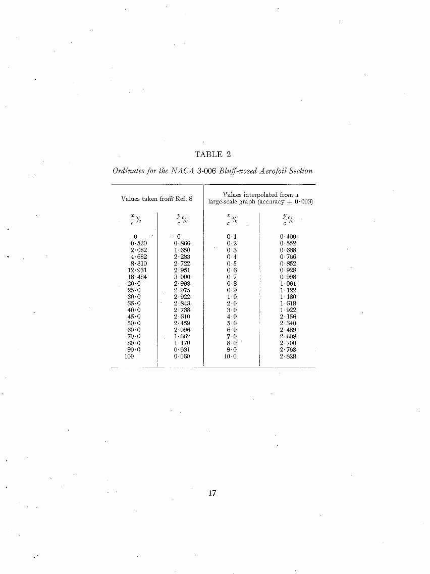
TABLE 2
Ordinates for the NACA 3-006 Bluff-nosed Aerofoil Section
Values taken frofff Ref. 8
X o ~o
0 0.520 2.082 4.682 8.310
12.931 18.484 20 .0 25 .0 30 .0 35 .0 40 .0 45"0 50.0 60.0 70.0 80.0 90.0
100
Y o/ - / o .
0 O. 866 1.650 2- 283 2- 722 2.951 3.000 2- 998 2.975 2.922 2- 843 2. 738 2-610 2- 459 2- 096 1- 662 1 : 170 0-631 O. 060
Values in te rpo la ted from a large-scale graph (accuracy ± 0-003)
X o
0.1 0 .2 0 .3 0 .4 0"5 0 .6 0"7 0-8 0 .9 1.0 2 .0 3 .0 4 .0 5"0 6"0 7 .0 8 .0 9 .0
10.0
Y O
O" 400 O" 552 O. 668 O. 766 O" 852 O. 928 O" 998 1 . 0 6 1 1. 122 1. 180 1.618 1.922 2. 156 2. 340 2.489 2. 608 2. 700 2. 768 2. 828
17

TABLE 3
Ordinates for the Wing Sections of the Revised Droop Modification
Sta t ion
~1C,.%
0 0"1 0-2 0-3 0"4 0-5 0-6 0-7 0-8 0-9 1-0
1"2 1"4 1"5 1.6 1"8 2 2 .5 3 3"5 4 4"5 5 6 7 7"5 8 9 '
10
12-5 15 17"5 20 25 30 35 40 45 50
60 70 80
100
Inner Kink
1"035 Mean Line Ordinates
z/c~%
- - 2 . 3 0 0 - -2 .274 - - 2 . 2 4 9 - -2 .224 - - 2 . 2 0 0 - - 2 . 175 - - 2 . 151 - - 2 . 1 2 8 - - 2 . 1 0 5 - - 2 . 0 8 2 - - 2 . 0 5 9
- - 2 . 0 1 5 - - 1 . 9 7 2 --1"951 - - 1 . 9 3 0 - - 1 . 8 8 9 - -1"850 - -1 .754 - -1"664 - - 1 . 5 7 9 - -1"499 - - 1 . 4 2 3 - -1 .351 - - 1 . 2 1 7 - -1 .095 - - 1 . 0 3 9 - -0"985 - - 0 . 8 8 4 - -0 -792
- -0 -594 - -0 -436 - -0 -309 - -0 -209 - -0 -075 - -0 -011
0 0 0 0
Thickness Ordinates
Z,lC.%
0 0.432 0.606 0.733 0.841 0-935 1.019 1-096 1-168 1-235 1-298
1.415 1-519 1.566 i -612 1.699 1.779 1.959 2-112 2-250 2.367 2.472 2-566 2.723 2.840 2.890 2.935 3.016 3.090
3.234 3.353 3.445 3.522 3.659 3.739
3 . 7 4 0 3.661 3.503 3.284
2 '732 2"080 1 '387
0
Outer Kink
1.040 Mean Line Ordinates
z./c~%
- -2 -500 - -2-461 - - 2 . 4 2 3 - -2 -387 - - 2 - 3 5 2 - - 2 . 3 1 8 - -2 .285 - - 2 . 2 5 3 - - 2 . 2 2 2 - - 2 . 1 9 2 - - 2 . 1 6 2
- - 2 . 1 0 6 - - 2 . 0 5 2 - - 2 . 0 2 7 - -2 .001 - -1 .952 - - 1 . 9 0 5 - - 1 . 7 9 6 - - 1 . 6 9 6 - - 1 . 6 0 4 - - 1 . 5 1 9 - - 1 . 4 4 0 - - 1 . 3 6 6 - - 1 . 2 3 2 - - 1 . 1 1 2 - - 1 . 0 5 7 - - 1 . 0 0 5 - -0 -908 - -0-821
Thickness Ordinates
z,/c~%
0 0.400 0.560 0"678 0"778 0.866 0.943 1-014 1.081 1-143 1-202
1-309 1-404 1-449 1.492 1-572 1-648 1-814 1-954 2-070 2-173 2-263 2-342 2-468 2-570 2 .619 2-662 2 .736 2.802
2.940 3.046 3.141 3.219 3"349 3.435 3.489 3.493 3.404 3.229
2.718 2.080 1.386
0
Projected Tip
1. 040 Mean Line Ordinates
z./c~%
- -1 -643 - - 1 . 6 2 2 - - 1 . 6 0 2 - - 1 . 5 8 2 - - 1 . 5 6 2 - - 1 . 5 4 3 - -1 .524 - - 1 . 5 0 6 - - 1 . 4 8 8 - - 1 . 4 7 0 - -1"453
- - 1 . 4 2 0 - - 1 . 3 8 7 - - 1 . 3 7 2 - - 1 . 3 5 6 - - 1 . 3 2 6 - - 1 . 2 9 7 - - 1 . 2 2 9 - - 1 . 1 6 5 - - 1 . 1 0 6 - -1 .051 - - 0 . 9 9 9 - - 0 . 9 5 0 - - 0 : 8 6 0 - -0"779 - -0"742 - - 0 . 7 0 6 - - 0 . 6 4 0 - - 0 . 5 8 0
- -0 -635 - - 0 . 4 8 5 - - 0 . 3 6 5 - -0 .267 - - 0 " ! 2 8 - -0 .045 - - 0 . 0 0 6
0 0 0
- -0 -450 - -0 -345 - - 0 - 260 - - 0 . 191 - - 0 - 092 - - 0. 032 - - 0- 004
0 0 0
Thickness Ordinates
z,/c,,%
0 O. 286 O. 400 O. 484 O. 556 0.619 O- 674 O- 724 O- 772 0-816 O. 859
O" 935 1.003 1.035 1. 066 1- 123 1- 177 1.296 1- 396 1-477 1- 547 1. 607 1 . 6 6 1 1.748 1 - 8 2 1 1.856 1- 886 1- 944 1. 995
2- 097 2. 175 2 .243 2. 300 2.392 2.454 2.492 2.495 2.431 2- 306
1.941 1.486 O- 990
0
C, the original chord length of the basic design.
C~ the ex tended chord length of the modified design.
The t ra i l ing edge of the wing r e m a i n s u n a l t e r e d , and the wing-root sections inboard of 0 .25 semi-span are the symmet r ica l sections of the basic design.
The d a t u m line in the above tab le of sections coincides wi th the chord line of the symmet r ica l sections of the basic twis ted wing, and the thickness ord ina tes are set off from the mean line in a direct ion normal to ti le d a t u m line.
18

F~SELAGE HORIZONTAL DATUM
C
MODELSCAL¢ 0 3 6 9 t2 INCHF..~
FIG. 1. General arrangement of half-model.
The half-model installed in the high-speed tunnel.
FI6. 2.
(8~201)
19 B

bO
R = 1.3 x i O 6
. f i e f -0"8 /./o ,.~
i I FIG. 3. CL vs. ~ at constant Mactl number for the model wi thout tailplane.
ORl~ M : O - 4
ORIGIN
M=l
ORI~ FOR
ORIGIN FOR M : 0 . 6 5
R= I ' ~ x [ 0 6
T L T = - 5 °
" ~ ' - - ~-r = - I °
- 0 . 0 5 O.'Z 0 . 4 0 ' 6 0 " 8 CL - I-O
FIG. 4a. C,,~ vs. Cz at constant Mach number for three tailplane settings and model without tailplane.
, i t t t

o v
t ~
P,'=I "3 y.tO ~'
--e-- TIT. -5 °
~ "qT t - I "
omc~,~ Fo% o " " =0.9 - " - 4 ~
' \ O.Z 0 - 4 0 '6 0-65 C~ I '0
FIG. 4b. C,,~ vs. CL at constant Mach number for three t a i lp lane se t t ings and model wi thout tai lplane.
M= 0.95 • "
/ M • 0 ' ~ 0
o___ _o___~ / k4:0.85
I ~ "e'--'-'e j
M :0 . '7
Io.-/ o_.._ _o___.--o ~
M : O . 4
. / 0.2 0.4- 0.(3 0 ' 8 CL I,O
C~ vs. Cz at constant Mach number for the model w i thou t ta i lp lane.
F I G . 5 .

N.~. FALSE ZERO
O-O5
-0 .O5
Cl"~.4ti ~
0.5
I CL = 0
. _ _ . ~ CL- = O'Z
1----'-'=-~ --- ~ . 1 o.b 0.7 0"~ ~ i ' \
CL.: 0 -4 \ M
5.0
'Z'O
1,0 0 .~ 0 ,5
N.5 FALSE ZERO
4.0
0'6 0"'7 O'8 O'9 M b3 bO
3.0
2.0 0.4
FIG. 6.
~c~ I I - ~ - )PER RADIAN 0 <C L
/
< 0 ' 3
/ / J
/
TAILPLANE LIFT CURVE SLOPE -O-I<C,_ T 4 +O'l
. . . . ~ ~ . . ~ . - - - - - - -~
0"5 0 ' 6 0:'7 O'~ 0 .9 M
Variation with Mach number of pitching moment, induced drag factor and lift curve slope for the
model without tailplane.
t Cm: 0.050
l t
LRI~IN ~---- 5 - ~:4,4 ×~0 6
D R ~
]RIGIN R:l'3xlO~
- . . e - - R = l . 3 x l 0 6 M = 0 - 1 5 ) NO -.¢-- R = 3'0x10 6 M =O'15
R = 4 '4x l0 6 M :0 '15 TAIL- R = 7"O:~106 M =O'Z5 PLANE
6--------o---- - ' -¢--"~-- ' -¢ o---
0'2 0.4 0 '6 0"5 C L I'O
FIG. 7. Effects of Reynolds number C,, vs. C,. and CL VS. ~.
4 q

O.OZ
0.04 _~__ C ~ C&p=-o 1TA" L
/ /
0'02
I ' 0
"~ = 1"44
~ x I O ~ M,O'ZS]
0.04-
Co?
0"04 Cop
'O.Z . 0.2 0.4 0.6 0.8 QL t.O 0,4 0 '6 045 C~ I '0 2
0'04 Co.p
r R:l.3xlO~, M=O' I51 0 0 ~ -k= [.60 /
~r ._ . .~_~ ~ ~ - - - --~ ='~'4 xlO ~' M=O'I5 [
0.2 0 .4 0.6 0 '8 C L I,O 0.2 0 '4 0 '6 0"8 G~
FIO. 8. Effects of Reynolds number C~ vs. Cs.
WIN~ UPPER SLIR~'ACE
-- CL.EAN ~t.OW
. - ~EPA~A-rEO ~Low
- - - - - P ~ O J E c ~ o ~ o f v O R T e X coR~ oN VLN~ suRfAcE
0.~ 0 ' 4 0 .6 O.B C u
(C) ~ " 8"~ ° ~ - (~t) ~o IO.~ ° ie) ~ = • °
FIG. 9& to e. Oil-flow pat terns for the basic design at M = 0.23, R = 1-9 × 10⁶.
23 (82201) C 2

- - / //.~:,x~" ~ . . ~ . . / ' ,.,,SMOOTH P'LOW. Z~,-----------"W / / ;~ ?. .: :.. - / - "TUFTS UNSTEAD','.
o L%-~ ~ ~ / x ff 7' " I-I --~ TUFTS OSCILL,~-I'ING,. (0..),=6"Z /_~..~-- J (b) ~-.8"~X~.~...I~I/ ' XX× TLIF-['.~ V,0IENTL'( .
/ - ' ___/ /~ , ~ z . ~ Z _ _ _ / o~s'rua~,E.o ,~ s~PaaAr~o
-- -- • ~ L o,z 0.4 o,6 o.8, c.
FIG. 10a to e. Tuf t - f low p a t t e r n s for t he basic design a t M = 0 .4 , R = 1 .3 X l0 G.
o )~.~ .X j F T /
/ Z ~ . A ~ 1 / 1 Z____--- :4 ":'> ,
WINI~ UPPER SURFACE
SMOOTH .FLOW, TUFT6 UNSTEADY.
---) - - ) TUFTS OSCLLLA"f lN~.
X X X TUFTS V IOLENTLY DISTURBED iN SE:PAR A'Tg D FLOW
Cm I J ~ j M : 0 ,9 R = 1'3 xl0 6 (TUFTED)
-,05 0.2 0 .4 0 ' 6 0 .~ CL
FIG. l l a to e. Tuf t - f low p a t t e r n s for t he bas ic design a t M = 0-9, R = 1 .3 × 10 6.
t
2 4

; t
Smooth wing. 0.01 in. carborundum, L.E. 10% both surfaces.
0.01--0.02 in. rough paint, L.E. 10% both surfaces.
Wing with tufts (0.015 in. dia.).
Upper surface transition, indicated by sublimation technique.
(82,~00
--o- SMOOTH w,Ne 7 i 0-0| # C.RRBORUNDUM t L.E I O ~ l l . r
' C, wt ~ o.ol-o.d2 = R.OUGH PRIN"'~ ~.,IRFFiCES "
' ~ ,1 . . . . . i , ~ ~ , ; ' ( ' , : i ~ :
• • . . ~ . 8 o , . , = ~-~ _ _ . ~ ,
" : : i ' I l : : : ; i : ~ ; c ; ' 2 : : : i : : : ° ' z i " ' : i ° r= ' i o e C L t
T " " " r T : 1 " " !
:::il I FZG. 12. Effects of surface roughness upon the stability of the basic design at high
Math number, showing transition position and C, vs. C~.
25 C,

['O Ob
0:7
Ct.
0 . 6
0"5
0'.4"
0"5
0"2
O.I
i ,
TWISTED WIN~ (SEE TABLF" 1- D . . . . WIN~ WI'TH COMSTAN4T INC_IDENCF-.
// /// "X \ \ \
/
/ ~ ~ ' - . / / \
_..._ ~ ~ = O °
o~ o~ o s - . . . . ~
FIc. 13. Calculated spanwise distribution of lift coefficient showing effect of wing twist.
0.5 I I -cp / ~ LOcAuc~=o
0'25 ~CA 3-007
0 I 0 O.Oi 0 . 0 5 0.1 0.2 0'3 0-4 0"5
-~ UPPER SuRFAC ~"
~c ]4.O - - E = 0 '5
-¢p ~ £AE. IOZ-~%
,Z.O ~ ~-00"7 t
fO 'O
8"0
LOCAL eL =0"64"7 (~ = IO °)
. . . . . . ~ R.A.E. I0~--7 %
I - - R A E. [O~--1% (WITHOUq" CRANK E'F"FECT~
6.0 t
/ , N AC,,k 5-00"7
o.o \ /
/\2 0
0-002 0'01 0 '05 O'[ 0'2 0 " 5 O"~ 0"5 O --~ UPPE~ SIJRFAC~
F I G . 14. C a l c u ] a t e d p ressu re d i s t r i b u t i o n s a t t h e o u t e r k i n k . M ---- 0.

b~ -..1
I%
0
-I~
((]) FIRST MODIFICATION. ~ . . - ~ - ' ~ _ -
f I "NACA 3-oo6
/- I B~EBNER cAMBER LINE (-m =0.5)
/1\ Jf' EAN L,NE
~ " - FAIREO FeE)FILE ~x,,,... NACA 3-OOb. ~ ' - ~ /
( b ) REVISED MODIFICATION.
NACA 3 - 0 0 6
IL ,
o [ I ~,o% I p z ~O°/o
- 1% AN LINE
_~ ~ ,,~z/,IbASlC PROFILE. R.A.E. lO~--/~'a
,oL '~- - ..... -3 ;
FIG. 15a and b.
l E c
PROFILE OBTAINED Bh' DIFFERENCE BETWEEN UPPER ~,URFACE AND
THE. MEAN LINE
Construction of the modified sections for the Quter kink.
"'~'0
CL=O
-I.5
"I'D
R,A,E IOZ -'7 %
C FLRST DROOP MODIFICATION ....
C
REVISED DROOP MODWICAq'ION .....
d R AE. IO~-'7 % WITH REVISED CAMBER LINE
6' / / l /;'/
./
x / .,.f
• 0"1 -O'05 "0'01 I
.O~/ER SURFACE
'k
i111 / ,I # t
[ / / UPPER BUR FA~E.
// i~t 5 # !
/ FIG. 16a. Pressure distributions for the modified sections, calculated for the case of an infinite swept wing. $ = 35 deg,
M = 0 .

J~
C~ n
-IZ
C~ : O-98
R.A.E. IO2--7 % FIRST DROOP MODIFICATION
I REVISEO Df:~3QP MQDIFICA-rlON '.R.A.~. I02-7 % WITH REVISED -
CAMBER LINE.
INME.R KINK TI= 0.4'36 40% BASIC CHORD
OUTE.R KINK "rl:Q'bg";' 50 %,BASIC CHORD
b~ GO
-I0
-0'1
( I .
I
/, %. r - 2 " 0 I
/ O O'OI 0 .05 O'Z O.3:= 0.4 0'5
I,o I I I I ~ 1 I LOWER SURFACE UPPER SURFACE
FIG. 16b. Pressure distributions for the modified sections, calculated for the case of an infinite swept wing. ~ = 35 deg,
M = 0 .
0'1 F
• PROJECTED TIP "rl= I 'OO 50% BASIC CHORD
~ NO MODIFICA-rION INI~OAI~D
< 2 INNER KiNK
NACA 3-008 FAIR~'D TO ~ASLC R.A.E. ~OI SECTtON OF "7.5% E LEADIN~ 30~ O~OOPED ~ A N D ~X'T~NDED ~.O%.OV~'RALL -~ ";.S-/%
OUTER KINK NACA. 3-OO/-, FAIRED "TO m, ASIC R.A.E. 101- ~ ,.SECTION OF"7.0%
LEADINCt 30% DROOPED 2.5 % AND EXTENDED 3,'25 %.OVERALL ~ 6~.97 %
PI:?OJECTED TIP RA.E. IOO, ° ~ 6 '/o ~, FAIRED TO BASIC R.A.E. IO4 SECTION
OF 5'O % ~ AT 65 % CHORD. NO DROOP OR ,EXTEN.51ON.
FIG. 17. Details of the first wing modification.
4 R

INNER KINK "q = 0 ' 4 ~ & 40% ~ASIC CHORD
,.l OUTSR KINK " r1,0-692
,50% BABIg CHORD
INNER KINK "rL:0'45,5
d<-_ 4-0 % BASIC CHORD
i
4-0 To BASIC CHOP,,D " OUTE.R KINK" T L, O-69Z !
I
C< -c i
1",3 C.D •• PROJECTED TIP 1"l. : l , O O 50 % BASIC CHORD
!
" ~ ~ FF..NC~B T~ST~D ON UPPER SURFAC~ AT '~= 0 " 7 4 - 4 AND O'~41
~ NO MODIFICATION INE!,OARD ~ 2..~ % SF..M ISPAN ,
\ "" -.. \ RM ". . . \ " - - "1- "~'
AXIS
INNER KINK N,A.CA: ~ - 0 0 6 5 FAIRE.D TO BASIC RA.E. IOI SF-CTIONI OF "7.5°/o-~ L!EADING I ~1% DROOPED "Z'~ % AND EXTE.NDED 3.5%.SLOPE OF MEAN LINF,.
AT L~, = 14 ° 3 ~
OUTER KINK NA.CA. 3 - 0 0 6 ~'AIRED TO BASIC R.A.E. I0~ ,..%IECTION OF-/.0% LC'ADIN~ 3B.&% DROOPED ;~'B% AND EXTE.NDED 4.0%,SLOPE OF" MEAN LINE AT LE..,:/I "~'~
PROJECTED "TIP NACA. 5 - 0 0 4 3 FAIRED 'TO R.A.E.IOZ,5 %~ (BASIC ,SECTION WAS R.A.E. IO4.,5%) LEADIN~ 35-6% DROOPED I,,'.-.4-~. EXTENDED 4.0%.SLOPg OF MEAN LINE. AT I r.ll°5.~
FIG. 18. Details of the revised wing modification. (See also Table 3.)
PROJE.CTED TIP "r'[= DO0 50% BASIC CHORD I
i I
\ PM. " ' " - - - - 4 - - - - % ' - - -
A'/,d £ INNF--R KINK N.A.C.A. 5- 0065 FAIRED TO BASIC R ,~F. IOI SECTION or -7,5 % {
LEADING 31% DROOPED 2.5% AND EXTENDED 3.5%. 5LOPF... OF MEAN LINE AT L E= 14°3 '
"OUTER KINK' SECTION AS FOR REVISED MODIFICATION BUT INCREASED B"( 15.8% ISABIC CHARD (Co) THICKNESS REDUCED TO 6"5% TC)TAL CHORD & FAIRED F'ROM MAY, THICKNESS INTO' BASIC RA.E IO'g-q %AT45%Oe,.DP,,OOP:2.b4%C 6 ~LOPE OF MlEAN
PROJECq'EO TIP LINE. AT LIE.=IB°4B ' N A CA. 5 -004 FAIRED TO BASIC.. R.A.EA04 SECTION OF B'0% {
LEAITIN~ 41,9% DROOPED 1"5% AND E.XTENDF..D 4.0%. SLOPE. OF MF-AN , LiME AT L.E." 6°5"5
FIG. 19. Details of the modification to remove the outer kink.

-I.0 R = I-;5 ~ IO 6 ,~.~.~,..,~
~-, . f j j ~ o,,
-o.~, ¢f/..a ~>:~.~. "~ "'
o. /y/y-i,-/ - 0 ' 4 I / ,
/oj~/,#
FIG. 20.
REVISED DROOP MODIFICAT"-I • E ' - - ~ - ' ~ - OUTER KINK REMOVED I
/ X # °
. , _ ~ , = 5 ° . _ _ ~
C~ vs. e at constant Mach number for the model without tailplane.
C'r".411~ "
- - 0 . 0 5
r ~ - - O - - .
0 - - - - - -
0 - . . . . .
...... ~ ' ~ 0 ~
I - - e - - - REVISED DROOP MODIFICAT ~ - f / [ t - '÷'- DuTE~ K~NK R~'Mow'~ , / # ;
I I~ " e
J .~/~--~'~', / ' /
...~ I:~" ~" " I ~
- - e - - _ _ _ e
--;~bL=:
• L: L -
. t a , n F .
FIG. 21,
" - - q > _ ~
3 0.'Z 0-4- 0 ' 6 O ' B (2 L I 'O
C,,, vs. C~ at constant Mach number for the model without tailplane,
30

%7 ¢ , )5 " / 1.e
NO TAILPLANE Z.O"
TAILPLANE- SET AT ~.~-I ° --
aS 0"2 0"4 0 ' 6 0 ' 8 C L I.O
I + BASLE DESIGN ] RH'3xiOe - -0" - - REVISED DROOP MODIFiE&T N-
---9,--- OUTER KiNK REMOVED
SETA-r ~r; olo "".'~.. / '
J ~ - O , 0 5 - -~ ,~ ,~ ,
"-------0'10 O'Z 0.4- 0"~ 0"8 C L I '0
FIG. 22. C,, vs. Cr at M : 0 .4 and M = 0 . 9 wi th and wi thout ta i lplane.
0"10
Cm.,¢ll~.
0.05
0-05
I
0
R= I'~ x IO 6
"411F.
-0.05
0
.REVISED DROOP M O D I ~
-O.OB
FIG. 23. character is t ics of
MODIF"ICA"TION WITH 3LJ"rER KINK REMOVED /
0- .'.'Z 0 .4 0 ' 6
, SMOOTH WIN(~ SU.RFA{~,E I - - - - - TUFTED W N~ SURFACE I
REVI~SED DROOP MODIFICAq'IONt/~/
MODIFICATION W i'-I'H OUTER KINK REMOYE.D"
/ 0 8 CL [.0
.-9'- /
O.'Z 0.4- O'b 0 .8 C~ I.O
Effects of tu f t s upon the p i t ch ing-moment the modif ied designs for the model wi thou t ta i lp lane .

03 tO
R = I . 3 × I O 6 1 J
P ~As ,o DES,~N / I - - - REWS~O dROOP ~40Di~tCa~-~ I I - - °uT mR KiNK RE~OVEa /
0.1~ - - e / l " ~" / / / \ . ~ .....
/
, i I
o-o'~ I ; ; . " .1" I i I I
i i / i i ~ , 1 " Cu:O. 5
O'O& ~ ~ , ~ 1 . i l j ~ . ~
t - ' ~ i CL- = 0 . 4
0.04 . . . . . . - - - o ~ - = - - . - -
~ = ° K . ~ -S ~ . ~ : - ~ ' ~ _ f . ~
O,OZ ~ _ ~ - ~ - a = . . . . . = ~ - - ~ T - . . . . /
C~: 0 ~
m L F J
--e-- R¢~4SED DROOP MODIFICATION I ~= 6.5 x 10⁶ --b'- OUTER KINK ~KMOVED l /M ~ 0 - ~
/ ~ - ...e. b " " R =" / . 0 × i 0 6
/ ~
R=4.4×IO a l / e / M:o-15
/~ /, I / ~ 4),.. ..4y. .,.e ~=3.0 ×lO 6
? I / o / / ' / / / / .'1
0 / / / , 5 ° I O ° ¢ 5 ° 2 ~ ° ¢ . 2
0 ' 4
FIG. 24. 0.5 o.& o--7 0"8 M 0 . 9 bo
Ca vs. Mach number at constant C~ for the model w i thout tai]plane.
FIc. 25. Effects of Reynolds number. Cz vs. ~, model without tailplane.

¢.aO
FIG. 26.
- -e - - - R[ylSED DROOP MODIFIC#,T-N l ~ .2 f ~, OUTER KiNK REMOVIED I IR:';'Ox~O~l y i -
I 2"" __~-" LM:o.=z ~___#_- ~- . . . . ~ . . ~ . . . . . . -
• J -:%:~:4'. ~
#
'
. . . . .4>" . 0 / ......... ~-- --" : . - - e " "
0 "2 0 '4 " 0 .~ 0 ' 8 CL 1,0
Effects of Reyno lds n u m b e r . Cm vs. C~, m o d e t without tailplane.
_ _ BASIC, DESIGN - - e - - REVISED DROOP MODIFICAT- N . [ I ---'~-- OUTE.R KiNK REMOVED / I
C°~ - - - ' R' FACTORS:- ~ ~ ' , . _ _ ! ~ I R×~o ~ , ~.~ ~.o +4 6.5 7.o I /IRq'o_*J_Oq :
0-04.. 5ASIC DE$Ir~N I.SB 1.59 1.60 1.441 / IM_=U ~ I
NO OUTER KINK 1.44 I.g7 I / I / ~
I I
: i
o l i l I
/ , ./i
0,02 / "/ - - ~ - - - . ~ - ~ = ~ ..~v'"
/
o /
./ / O. 02 ~ / J
. . . . ~--- ~ - - ~ - ~ : , ; ~ - - - . - e . . . . . o- . . . . . ~"
/ /I oz o / #i! II [R:I'3×IO~ l i
p4° o.l__s ,' /
O. . /
0.2 0 '4 0 ' 6 O.8
FIG. 27. Ef fects of R e y n o l d s n u m b e r . m o d e l w i t h o u t ta i l p lane .
1,0
C~p vs. CL

0,3
t C.: i " 2
/ : { / ,.,r'/,f = g ~
o //) o
FIG. 28. Fence tests at low Mach number. Cz vs. % model without tailplane.
R:4 .4x lO 8 M=O.IS
R - 5 ' 0 x / 0 t' M~Od5
R : i . S x i O ~' M=O'I5
M = 0 . 4 R=l ,3x lO e
o . l o
0.05
O.lO
li~__ " BASIC DEBI~N FENCE AT
FIRST MODlr-'ICATION ~ : 0-24"4 RF,.VISED MODIFICA"rlON -q. = 0-641 REVISED MODIFICATION ~, O'q4,4&O'64"l
0"2 0 '4 O' 6 0"8 C L I- o
o o.~ i
~-~_~--~ ~ - ~.~
0.2 0 -4 0.~ 0 . 8 CL. 1.0
o. lo
- ' / /
0"2 O"4 O.lO
Cr~.41[~ [M=O.~ R=I-3~IO 6 ]
0.05
F I G . 2 9 .
O'b 0 '8 CL. I '0
o-~ 0 . 4 ' 0 . 6 0 .8 Q I -o
Fence tests at low Mach number. C,, vs. C~, model without tailplane.
&

WIN~ UPPER SURFACE
-- CLEAN FLOW
.... SEPARATED FLOW
----- PROJECTION O~' VORTEX CORE ON WIN~ SURFACE
WITHOUT ~ENCE :y Crm M =0"23 R=l'£xIO l
O'Z 0'4 0'6 0"8 I'0 / CI m WITH
FIG. 30a to e. Oil-flow patterns for the droop modifications with and without a fence. M = 0 . 2 3 , R = 1.9 × 10⁶ .
' ~ WIN~ ~JPp~ SUrFAce"
~ _ / - ' - - - - - - 7 _ o.~ o.~ o.~ o.s c,
FIG. 31a to e. Tuft flow patterns for the modified wing with outer kink removed. M = 0 . 9 , R = 1 .3 × 106 .
35 -
(82201) C**

T M,O'HLGH ~ T TA~LPLANE ~ ~ '
I / ' ~ " " " ' - ' - ~ TAILPt.ANE \ / / !
I I ! VERY LOW \ )
I ~ TAILPt~AI~E ~ I _~ ~ pos,'r,oN ~ ~ S,ANW,E ~.ANC o, ~,
I WAKE SURVEY RAKE LONGF'IrL}E}INAL PLANE
~'USELAGE HORI'LONTAL DATUM
ILPLANE MEAN NB. UNDER-FUSELAGE FAIRING ONI.'Y PRESENT IN COMBiMA'TION WFTH THE 'VE.RY LOW' TAIL.PLANE POSI'Tt0N
FIG. 32. General arrangement of the three tailplane positions tested with the wing modification of FIG. 19.
FIG. 33. Under-fuselage fairing to support the tailplane in the ' very low ' position.
36
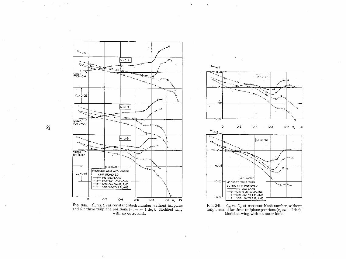
C~ "-.1
C~. 4l~;"
FOR M = 0"4 " '~ ' -~. . -~'~'~ --~ - ...~. . i.EL c~,,4:~."
°'~7-°~.°. i"'~. ~.
"~--,-~., ~
l "-..C C.,.,,., 0 • 05 R
%..~;.-..~_. ~-~
,
ORIGIN 0 -.-~...~.._ ~"x'a. FOR M :O"7 " '"- .~. . "-.. .~_._.~ - '~ '~- .
"9 . %. " . ? ..... ~. 'R
oRlal~ o . . . . -..~..-~--" ~'OR M: 0'8 "'~v--
".,.. "\ R = 1.5 × tO ~' %'J'.. " I ...,:... %
MODIFIED WING WITH OUTER "~ Cr~ =0'05. KiNK I~.EMOVEE) ~ ,
] ' ~ NO-rALPLANE ¢ ---&--- MID-HIgH T&~LPLANE "~
- - -~ - - MID-LOW TAILPL~,NE \ - - - ~ " - VERY LOW TA|LPLANE
\ %
O 0.2 0 '4 O.6 O,8 I'O C~ I.~
~'IG. 34a . C m vs . CL a t c o n s t a n t M a c h numtoe r , w i t h o u t t a i l p ] a n e a.nd f o r t h r e e t a i l p l a n e p o s i t i o n s (fl~ = - - 1 deg) . M o d i f i e d wing
w i t h no outer k ink.
C~.~.ll E
F I, T--- 0.0_ =
°
~---.~....._...~ "-. ".A.. J
x... ""-,c~.."'~"c . x , ". \-. "ok,.
\..
0
Cm.~tiE 0,05,
~e..~. " '-z
OUTER KINK REMOVED + NO TAILPLANE ---'&--- MID-HIgH TALPLANE
t~.__O.15 j ---a--MID-LOW TAILPLAN~" -.--~"-- VERY LOW TAIL.PL&NE
O.'Z 0-4 0 ' 6 O'B C L [.O
" - , i : '" . / ' ~,. \ . ~'~£.-~'~ ~
\ L _ _ ~..
FIG. 34b. C,, vs. Cz at constant Mach number, wi thout ta i lplane and for three tai lplane positions ( ~ = - - 1 deg).
Modified wing with no outer kink.

O0
C~'*ue 0'05 a...
- 0 . 0 5 " -~..... - ~..~,
-0,10 -... ,
"Nk.
"0"15 " \
0 0.2
C~ 0"05.
-"-~ ~ , ~'-\ " 2 - \ \ % -0.05
-O.lO
-045
R= I.'~ x I06 MODIFIED W1N~ WITH OUTER KINK REMOVED ---8--- NO TA1LPLANE --~--- MID-HICtH TAILPLb, NE ---~--- MLD-LOW T,~ILPLANE --~--- VERY LO~/-rAILPLANE
0.4 0 .6 C L 0-~5
J '~x, %t= "-.. - - - - a
\., " " - a .~ . N
\ . .
" ~ I'O
FIG. 34c. C. vs. C~ at constant Mach number, wi thout tailplane and for three tailplane positions (~IT = - - 1 deg).
Modified wing with no outer kink.
Cm'411ao-05 [m4.4x[o ~' M°O.15 I /
o ~ ~ ~ ~ - - - ~ 4 ~ ~ ~ ~--_ .~
- O - O 5 " ' ~
-OqO
0 0 '~ 0"4 0"6 0-~ CL. I,O I'~
O - I O
~m.4.lf E
O' 05
e.-- --''~'-'°'-" ~ - - - a . - ~
- 0 " 0 5
[__J__ ;~ = 1"3 x lO e M= 0'15 ]
i MODIFIED WIN(3 WITH OUTER KINK REMOVED
--e-- NO TAILPLANE --&-- MID-HIgH TAILPLANE --~-- MID-LOW "rbdLPLANE
"'6
/ J
/
'~--%v~..~
Fro. 35. Effects of Reynolds number on the s tabi l i ty with the mid- low tailplane position. ~/T = - - 1 deg. Modified wing with
no outer kink.

c D
HEIGHT I I I M = 0 - 4 1 I I I ~ / IDI3WNWA$ H I I I I I I
°'bl l MID.HI~H~o.~ 0 . . . . . . . . . . . . . . . . . . .
T 'I L'__ L_L I__ '_ ""J . . . . .u,,odI I, l b d ' , _ _ ~ ~ ~ s - A ~ & ~ Z / ~ _ ~,Lm/'Z~ ~ _ U G . . . . .
" ~ 7 Z ' / 7 - . \ - r - Y # \ ' , /
TAILPLANE-I ~'~" \1 \ I \ I x~. I ~ ~ ~" l L . . . . .
0.'~ 0 ' 4 . 0 ' 6 0 " 8 1.0 C~ (NO TAILPLANO
ZO ° MID MiD VERY DOWNWASH TAiLPLANE POSITION HIG~H LOW LOW I ~
F__ E FROM WAKE. SURVEY MEASUREMENTS I I,a. E DERIVED FROM AC,.,,OLIETOTAILPL#~NE a. a v
15 ° ~ ,/"' ,<
i I z
I iO ° l
,~ !
. / : k . i . / , , - - ' ~ , ~ "~ ~, /
5 °
- ~ ~ - ~ ' ; ~ . . / . . .w- ' - " " ' - '~ " "
:.c~:-" ~ ._I-~"- ' & .-
0 ~ j ' ' ' ' ' I r 0 ,2 0 . 4 0
0 ' ~ 0 " 8 I ' 0 C L (NO TAILPLANE~
FIG. 36a. Wake survey measurements at the tailplane (M = 0.4). Downwash vs. height and C~. No tail-
plane. Modified wing with no outer kink.
HEIGHT
0. '~5
MID-NIgH .ro.,2 o TAILPLAME.. t
O.IB FUSELAGE
OATU M
.OdO
MIO-LOW J TAILPLANEIo.0 5
WIN~ R O O T _ CHORE) PLANE U
VER,W LOW ~-0,05 TA~LPLANEL
-0-I0
15 °
DOWNWA&H £
I0 °
5 °
0 °
DOWNWASN 3o 4' 5 ° ,5""78°~ FO~II °
7 / - - :
// _ _
/
'9
0.2 0 - 4 0 - 6 O 'B C~ I .O (NO TAIL .PLANE)
FIG. 36b. tailplane and C~.
MiD MI~ VERY T A I L P L A N E POSFi'ION Hi - " '
F... FROM WAKE SURVEY M£.ASUREMENT5 il~_H _gO~q...17_OW - - E BE.RIVED FROM & CmDUE TO TAILPLANE A o v
l-4-:G:q r
i,- /
~ . : : - .~.~ ~"
:~---
0 'Z 0.4 0,6 0.8,. GL. 1.0 (NO TAII-PLANE)
Vqake survey measurements at the (M = 0" 9). Downwash vs. height No tailplane. Modified wing with
no outer kink.
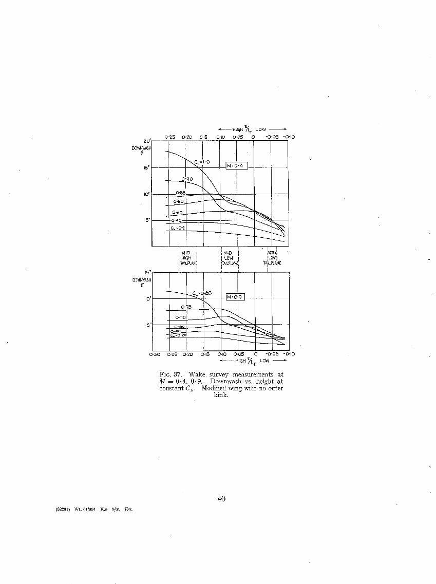
20"
DOWNWASH £
15 °
IO °
S o
15 @ DOWNWASH
E
I0 °
• ~'--"-- HIa~H 7L. r LOW 0'7.5 O'ZO 0.15 0"10 0'05 0 -0 '05 -0'10
\
0"90
O'B5
0.40 CL = O.'Z
I ML° 1 I HlqH [ iTAILPLAN['I
r r;3
----...__..
I - I I
~ D I IVERYI L o w ,, . Fow I
O.q5 ~
0,-/0 __
5' 0,0o . ~
0'~0 0"25 O'ZO 0'15 0'10 0'05 0 -O'05 -0"10 < HIgH ~/'LT LOW m.
FIG. 37. W a k e survey measurements a t M = 0.4, 0-9. Downwash vs. height a t cons tan t CL. Modified wing with no outer
kink.
(82201) Wt. 61/991 K,5 8/61 Hw.
4 0

R. & M. No. 3208
Publications of the Aeronautical Research Council
A N N U A L T E C H N I C A L R E P O R T S OF T H E A E R O N A U T I C A L R E S E A R C H C O U N C I L ( B O U N D V O L U M E S )
1939 Vol. I. Aerodynamics General, Performance, Airscrews, Engines. 5os. (52s.) Vol. II. Stability and Control, Flutter and Vibration, Instruments, Structures, Seaplanes, etc.
63s. (65s.)
I94O Aero and Hydrodynamics, Aerofoils, Airscrews, Engines, Flutter, Icing, Stability and Control, Structures, and a miscellaneous section. 5os. (52s,)
I941 Aero and Hydrodynamics, Aerofoils, Airscrews, Engines, Flutter, Stability and Control, Structures. 63s. (65s. 3d.)
1942 Vol. L Aero and Hydrodynamics, Aerofoils, Airscrews, Engines. 75s. (77s. 3d.) Vol. II. Noise, Parachutes, Stability and Control, Structures, Vibration, Wind Tunnels.
47s. 6d. (49 s. 3d.) 1943 Vol. I. Aerodynamics, Aerofoils, Airscrews. 8os. (82s.)
Vol. II. Engines, Flutter, Materials, Parackutes, Performance, Stability and Control, Structures. 9os: (92s. 3d.)
1944- Vol. I. Aero and Hydrodynamics, Aerofoils, Aircraft, Airscrews, Controls. 84s. (86s. 6d.) Vol. II. Flutter and Vibration, Materials, Miscellaneous, Navigation, Parachutes, Performance,
Plates and Panels, Stability, Structures, Test Equipment, Wind Tunnels. 84 s. (86s. 6/.)
1945 Vol. I. Aero and Hydrodynamics, Aerofoils. I3OS. (I33S.) Vol. II. Aircraft, Airscrews, Controls. I3OS. (I33S.) Vol. III. Flutter and Vibration, Instruments, Miscellaneous, Parachutes, Plates and Panels,
Propulsion. 13os. (I 32s. 9d.) Vol. IV. Stability, Structures, Wind Tunnels, Wind Tunnel Technique. i3os. (132s. 9d.)
1946 Vol. I. Accidents, Aerodynamics, Aerofoils and Hydrofoils. I68S. (I7IS. 3d.) Vol. II. Airscrews, Cabin Cooling, Chemical Hazards, Controls, Flames, Flutter, Helicopters,
Instruments and Instrumentation, Interference, Jets, Miscellaneous, Parachutes. I68S. (I7OS. 9d.)
Vol. III. Performance, Propulsion, Seaplanes, Stability, Structures, Wind Tunnels. I68s. (17i~.)
1947 Vol. I. Aerodynamics, Aerofoils, Aircraft. I68S. (I7IS. 3d.) Vol. II. Airscrews and Rotors, Controls, Flutter, Materials, Miscellaneous, Parachutes,
Propulsion, Seaplanes, Stability, Structures, Take-offand Landing. 168s.(17is. 3d. )
Annual Reports of the Aeronantieal Research C o u n c i l - 1939-48 3s. (3 s. 5d.) 1949-54 5s. (5 s. 5d.)
Index to all Reports and Memoranda published in the Annual Technical Reports, and separate lyq
April, 195o - - - R. & M. 2600 6s. (6s. 2d.)
Published Reports and Memoranda of the Aeronautical Research C o u n e i l ~
Between Nos. 2351-2449 Between Nos. 24-51-2549 Between Nos. 2551-264-9 Between Nos. 2651-2749 Between Nos. 2751-2849 Between Nos. 2851-294. 9 Between Nos. 295x-3o49
R. & M. No. 245 ° R. & M. No. 2550 R. & M. No. 2650 R. & M. No. 2750 R. & M. No. 2850 R. & M . No. 2950 R. & M. No. 3950
2~. (2s. 2,,'.) 2s. 6/. (2s. 8,/.) 2s. 6d. (2s. 8d.) 2s. 6d. (2s. 8d.) 2s. 6d. (2s. 8d.) 3s. 0s. 2d.) 9s. 68. (3t. gal.)
Prices i# brackets include postage
HER MAJESTY'S STATIONERY OFFICE York House, Kingsway, London W.C.2i 423 Oxford Street, London W.x ; x3a Castle Street, Edinburgh 2; 39 King Street, Manchester 2; z Edmund Street, Birmingham 33 Io9 St. Mary Street, Cardiff; 5o Faiffax Street, Bristol x;
80 Chichester Street, Belfast x, or through any bookseller.
S.O. Code No. a3-32o8
R. & M. No. 3208