criteria and assumpi'ions for numerical analysis...
TRANSCRIPT

781
Z.P.BAUm
PORE PRESSURE. UPLIFT AND F AlLURE ANAL YSlS OF CONCRETE DAMS MS
CRITERIA AND ASSUMPI'IONS FOR
NUMERICAL ANALYSIS OF DAMS
EDITORS: D.T. NA YLDR
I<.G.STAGG
D.C. ZIENI<lEWICZ
Proceedings of an International Symposium held at Swansea. U.K.
8 -11 September. 1975
organised by
DEPARTMENT OF CML ENGINEERING OF THE
UNIVERSITY COLLEGE, SWANSEA
in collaboration with the
BRITISH NATIONAL GOMMfITEE ON LARGE DAMS
and the
LABORA TORIO NACIONAL DE ENGENHARIA CML. LISBON
under the patronage of
THE INTERNATIONAL COMMISSION ON LARGE DAMS
and its specialist Committee on the Analysis and Design of Dams

782
PctU: PRESSURE, UPLIFT, AND FAILURE ANALYSIS OF CONCRETE DAMS
Z.P. BAbNT*
SUMMARY
The objective of the paper is a critical examination of the assumptions and equations
which serve as basis for the calculation of p'ore pressures in concrete dams, as well as the
His concepts of effective stress and uplift pressure with regard to failure analysis.
demonstrated that the water deficiency of concrete stemming from air-entrainment and self-
desiccation due to hydration tremendously slows down the penetration of the front of hydrau
1ic pressure .. Spacing and width of continuous cracks have a major effect on the penetratioa
rate. Drying affects only a shallow layer at downstream face. It is shown that, due to
anisotropy of the micro-stress state in hindered adsorbed water layers, the effective uplift
area should be distinctly less than 1.0 (about 0.9), even if over 99% of the weakest cross
section passes through water. Tests of deformation due to pore pressure are shown to be
incapable of providing the value of the uplift area and a value of 1.0 is shown to be most
reasonable for strain calculations, unless a two-phase medium model is developed. The pro-
b taken into account in calculatiOns of dam failure as gressive nature of fracture must e
well as test data evaluation. Concrete in dams cannot fail by shear (sliding) without vo1~
ume expansion (microcracking), and so temporary suction is produced in the vicinity of fai1-
ure surface. Ia the approximate nonlinear triaxial stress-strain relations for concrete,
the effective stress based on effective porosity n' - 1.0 may be used for the elastic stre ••
increments, while in the expressions for inelastic strains the (non-incremental) effective
stress based on the actual n r should be used. A rigorous formulation in terms of an inelaa-
tic two-phase medium is also indicated ..
INTRODUCTION
distributed loads (body forces) within Gradients of pore pressures produce significant 1 f f must be resisted by the
concrete dams. These loads, which are usually called up i t orces,
to a sliding failure or an overturning failure solid microstructure of concrete and can lead of the dam. Prediction of pore pressures and uplift forces is, therefore, of considerable
* Professor of Civil Engineering, Northwestern University, Evanston, Illinois, 60201, USA.
783
importance in the design of gravity dams. Catastrophies which were clearly attributed to
uplift forces occured already in the 19th century and keen attention has ever since been
devoted to the question of uplift. However, despite research efforts spanning over 70 years,
certain questions still remsin unanswered. They include: Should uplifS be allowed for in
jOints and cracks only or within intact concrete? How should the pore pressures be calculated?
Over what fraction of the total area of a given cross section are the pore pressures applied?
How should the deformations and failure due to pore pressure be determined? The following
analysis will address these and other related questions, and attempts to clarify several
controversial points will be made.
DETERMINATICII OF PctU: PRESSURES
In greatest generality, diffusion of any substance in an isotropic porous solid at
negligible temperature gradients is described, according to irreversible thermodynamics, by
the re la tion :
:;! = -c* grad I> (1)
in which ~ - mass flux vector (whose components represent masses that pass through the sides
of a unit cube in a unit time), I> m Gibb's free energy per unit mass (also called chemical
potential), c* - coefficient that may, in general, depend on state variables. Eq. 1 may be
adopted as the common ground for the diffusion laws of water in both the saturated and non-
saturated concrete. The effects of temperature will be neglected in this study.
Saturated Concrete.
It may be assumed that solute concentrations gradients have a negligible effect on water
diffusion. Then, for saturated concrete at uniform temperature, I> m p/pw + 1>0 [5J where
p = pore pressure in excess of atmospheric pressure [3J, Pw - specific mass of liquid water
(-1000 kg/m3 ), 1>0 = constant (depending on temperature). Eq. 1 may then be reduced to the
familiar Darcy's law:
(2)
in which c = c*gw/ pw2 ; ~ - unit weight of liquid water (-9806 N/m3 ); p/~ = hydraulic head
(dimension of length); c = permeability (dimension of m/sec). The capillary water content,
w, defined as the mass of capillary water per m3 of concrete, is related to pore pressure p:
(3a)
in which ~ = compressibility of capillary water in concrete, with account of porosity.
The change in water content is related to the flux field by the equation of conservation
of mass: div ~ = -bw/bt. However, if the hydration reaction proceeds simultaneously with
diffusion, this equation must be corrected for the amount of water, wh
' that is withdrawn
from the pores of cement paste due to the hydration reaction; i.e.
bw bwh div :;! - - lit + bt (3b)
In some recent works it has been assumed [lJ that wh equals the amount of chemically combined
water. However, this is incorrect because the volume of cement gel is larger than the volume

784
of anhydrous cement (about twice as large). On the other hand, wh
is not zero because the
volume of cement gel is less than the combined volume of water and anhydrous cement from which
the cement gel was combined. Consequently, the volume of capillary pores decreases with hydr~
tion and the part of th& chemically combined water which initially occupied the lost pore spac,
Fig.l must be excluded from the water withdrawn from the pore space by hydration. Powers [25) bq
estimated that the amount of water, wh ' that has been withdrawn from the pores of cement paste
is about 28% of the amount of chemically combined water, and since the latter equals about 221
of the weight of cement(after prolonged hydratimV,the water deficiency represents about 281
x 22% = 6.2% of the weight of cement. For lean dam concrete (without pozzolans) containing
112 kg of cement per mO of concrete, there is thus, after prolonged hydration, a water defi
ciency of wh = 0.062 x 112 & 7 kg of water per m3 of concrete, approximately. (For recent COn
cretes with pozzolans ~OJ, containing as little as 43 kg of cement per mO, the water deficiency
is about 3 kg/mO.) The foregoing value may be used as the final value, wh
- w~. The time
variation may be taken in the form wh - w~ f(t) where f(t) is an increasing function with f(O)
- 0 and f(=) - 1, possibly of the same form as the function defining strength increase with ag ••
To account for the changes in hydration rate due to temperature changes, t in f(t) may be
replaced by the equivalent hydration period, te [3-5J.
Substituting ;[ and dw from Eqs. 2 and 3a into Eq.3b, one gets ~pw bpi at - div [cPwgrad (p/gw) J
+ awh/bt, and noting further that c, as well as pw and ~, is almost constant with-
in the range of p-values of interest, it follows:
c with
C - ~~ (4 )
in which gO - div grad - Laplace operator, and C - diffusivity of pore water in saturated con
crete (dimension m~/sec); wh - function of time that must be prescribed. Eq. 4 is the familiar
linear diffusion equation and methods of its solution are well known. However, the numerical
values of material parameters deserve some discussion.
Permeability is easier to measure than is diffusivity. For leqn concretes which are
typical for dama, permeability c 1s of the order of 10-10
m/sec and a typical value is
c '" 50 X 10-12
m/sec .
0) b) 1:.::!:::::;:::!Z;:Z:;::!;lElt---air (water deficiency) - - - -- - - --- - - ,=->ooj---copillary water
cement gel (with hindered adsorbed
woler and Co (OH)2)
~~~~~~ ___ lInhydrous cement
Fig. 1 Change of Capillary Pore Space and Water Deficiency Caused by Hydration
(5)
785
For a concrete with 112 kg of cement per nf of concrete, Carlson has observed the values 175,
60 and 40 x 10-12
m/sec at ages 3, 12, and 24 months, respectively [12J. For the newly intro
duced very lean concretes, with as little as 43 kg of cement per m3 , 70 to 200 kg/mOpozzolans
and 80 to 150 kg/m" water, the permeabilities at age of 3 months range between 6 X 10-'Om/Eec
[20]. These permeabilities are several orders of magnitudes higher than those for dense struc.
tural concretes; but permeability of intact concrete has little effect on leakage through grav.
ity dams, as compared with the effect of cracks and jOints.
To determine diffusivity on the basis of permeability, compressibility ~ must be
estimated. If the solid structure of concrete were perfectly rigid, ~ would equal n~w; "~","
bulk compressibility of liquid water (about 0.00049 m2/MN at room conditions) and n = capi
llary porosity = volume of freely compressible water = volume of capillary pores per unit vol
ume of concrete. Not all water in concrete, not even all evaporable water, should be included
under n. The non-evaporable, chemically bound water must be excluded because its molecules
are part of the solid structure. The water molecules in hindered adsorbed layers [5],
even though they are evaporable, should probably be also excluded, at least in part, because
their equilibrium spacing is fixed by the molecular structure of the solid surfaces. This
leaves the capillary water and unhindered adsorbed water, which is all water that is contained o
in pores more than 10 molecules (26 A) in thickness. The weight of the freely compressible
water equals the total weight of water in the mix, minus about 30% to 40% of the weight of
cement before hydration (in a mature concrete). Clearly, n is decreasing with age (degree of
hydration), and so does~. (Hence, diffusivity must be increasing with age faster than per
meability, but no data seem to be available to this effect.)
In determining B one must further include the dilation of pore space due to dilation of
solid structure produced by pore pressure. This quantity depends on whether this dilation
occurs at constant total stress in the porous material, or at constant effective stress, or
at some other condition. Since the overburden of a given element of concrete remains constant,
a constant total stress is probably the most representative condition. It has been derived
for saturated sand that ~ - n~w + (1-2n) Cb where Cb - bulk compressibility of the porous
material at constant pore pressure (Cb - l/K, K • bulk modulus); see Eq. 53 of Ref. [8J.
For concrete, this relation certainly does not hold exactly. but probably it can be applied
as an approximation. Considering concrete of strength 24 MN/m2(3500 psi), elastic modulus
E • 23000 MN/m2 (3 336 000 psi) and Poisson ratio v - 0.18, one gets C = (1-2v)/E - 27.8 x ~ a b
10 m /MN. Furthermore, considering concrete of 112 kg of cement and 80 kg of water per mS ,
and an aggregate of porosity of 1%, it may be estimated that n '" 0.05. The foregoing approxi
mate formula for ~ then yields ~ ~ (0.05 x 490 + 0.9 x 27.8) 10-8
& 50 X 10-8
m2 /MN. Note
that this value is close to Cb ' bulk compressibility of concrete.
The preceeding derivation confirma the empirical observation of Murata [2lJ that compressi
bility B in the relation of diffusivity to permeability should be taken apprOXimately as the
bulk compressibility of concrete. A typical value of permeability of a I-year old lean dam
concrete is 50 x 10-12
m/sec, and this yields, according to Eq. 4,
(6)
which is the upper limit of the diffusivities of concretes as determined by Murata [21J from
penetration depth testa.

786
The depth of penetration of hydraulic pressure for wh = 0, pertaining to one-dimensional
diffusion into an infinite space x ~ 0 exposed to water of pressure PO at x ~ 0 for t ~ 0,
may be found from the following well-known solution of Eq. 4 [13):
2 SOO _82
p(X,t) a Po erfc (s) a Po ~ S e ds, (7)
in which erfc = complementary error function. Defining the depth of penetration as the dis
tance from the surface to the point where p • PO/lOO, one can find from a table of the error
function that S • 1.820. For example, consider a 100m-high gravity dam which is 80 m thick
at the base and neglect the water deficiency due to hydration, setting wh • O. Then, the tt.e
(after filling of the reservoir) needed for the penetration of the full thickness of dam is
x· 80· t • ~ - 4 x 10-4 x 1.82" sec /, 56 days (for C • 10-4 m/sec) (8)
This is a relatively short time, which contradicts the 'fact that only relatively small
pressures have been observed within the mass of concrete in dams [26, 15, 17, 10J (while
within cracks and cracked construction joints high pressures are observed (22). In reality,
there indeed exist phenomena which tremendously prolong the penetration time.
The water deficiency wh created by hydration is one such phenomenon. An approximate solu
tion of Eq. 4, valid for sufficiently long time periods, may be obtained by sssuming that
hydration becomes nearly complete before the hydraulic pressure front arrives. Thus, air-fill ..
voids are produced by hydration in concrete before the arrival of the front. This phenomenon
is called self-desiccation and is manifested by a several percent drop of humidity below 100 per
cent (23). It is thus clear that the build-up of hydraulic pressure in concrete requires not
only the supply of water necessary for elastic compression or pore water, but also the supply of
water necessary for filling the pores. The latter amount is much higher than the former one
and must have an overriding effect on the rate of penetration of the hydraulic pressure front.
Assuming that the rate of advance of the front is diminished by orders of magnitude, the
pressure distribution between the surface and the front will nearly equal the stationary
distribution for the case of immobile front, which is a linear distribution. Therefore, the
amount of water (per m") that must be supplied to the front in time interval dt is Jdt
pwc(po/gwx)dt. Furthermore, because water diffusion in non-saturated concrete is very slow,
the water deficiency just ahead of the front should be almost the same as that far ahead of
the front. Consequently, Jdt = whdx, where dx = advance of the front during dt, wh = water
deficiency per m", estimated in the foregoing. Hence, xdx = (pOcPw/whSw)dt. Integration
gives ~x2 = PoctPw/whgw' and so the time of penetration to depth x = 80 m at the base of a
100m-high dam is
7 80"
1000 2 x 100 x 50 x 10-12 s ec ~ 142 years (9)
considering the permeability to be SO x 10-1• m/sec. Eq. 9 is not valid in a region close to
the upstream face because hydration is not complete before the arrival of pressure front. In
this region it is possible that pressure first builds up and is subsequently reduced to zero
(unsaturated condition) due to the term wh in Eq. 4, as is indeed observed experimentally [5J.
787
Another reason foy the initial lack of saturation of concrete is air-entrainment, nec~
essary for good worksbility at low water and cement contents. Typically, air-entrainment rep
resents 6% of the volume of concrete, which indicates water deficiency of 60 kg/m3, in addition
to 7 kg/m" due to hydration. According to Eq. 9, the penetration time is then extended to t =
1360 years, a value which is practically irrelevant, of course. The effect of air-entrainment
on the penetration time has been previously analyzed by Carlson (12) and he obtained a similar
result. The depth of penetration which is reached within a lOa-year period (3156 x lOS sec)
is, according to Eq. 9,
(
1000 ,) \ _ --- 2 x 100 x 50 x 10- a x 3156 x lOS m ~ 21.7m (10)
60 + 7
which means that only about t of the dam thickness could receive hydrauliC overpressure if
concrete remained free of seepage channels such as cracks and leaking construction joints
(Fig. 2). This seems to agree with measurements of pore pressures in dams [26, 15. 17, 10J.
E o o
Fig. 2
saturation front
years
Advance of the Fronts of Saturation and of Drying in an Ideal Dam Having No Cracks, No Cracked Joints, and No Drainage (for a Typical Concrete)
Eqs. 9 and 10 are based on the assumptions that concrete is intact (uncracked), no
seepage channels through the dam exist, and no upward diffusion from the bedrock takes
place. However, even if these assumptions are inapplicable, the value of diffusivity is
clearly irrelevant for the build-up of pore pressurea inside the dam, except very near the
upstream face (or near the seepage channels).
Regarding the effe~t of deformations of concrete on diffusion, Eqs. 3a and 4 include
only the deformation due to pore pressure, but not the deformation due to loads applied on
concrete. This effect, which must be as significant as the deformation due to pore pressure,
can be rigorou.ly formulated only with the help of a two-pha.e medium mod.l ( ••• Eq •• 40 in the

788
sequel, which would replace Eq. 3 and yield a diffusion equation more involved than Eq. 4).
However, in practice the changes of pore pressure due to deformation do not appear to be too
important because they are small in comparison with the effect of initial water deficiency
of concrete upon the subsequent burld-up of pore pressures.
Non-Saturated Concrete.
As has been mentioned, concrete of the dam tends to remain unsaturated for a long time
because of self-desiccation and air-entrainment. Further loss of water occurs by drying fro.
the downstream face exposed to the atmosphere. A detailed study of water diffusion in non
saturated concrete has been given in Ref. [3J and only the most pertinent facts will be
reviewed herein.
The problem can be formulated either in terms of the specific water content, w, or in
terms of capillary tension or surface tension, or in terms of relative vapor pressure h in
the pores (pore humidity). The latter variable is probably most convenient because, among
other reasons [3], h is at the same time a characteristic of the environment. Assuming
ideal gas approximation for water vapor, the Gibbs free energy per unit mass of pore water
may be shown to equal ~ • (R/M) T ln h + ~o where R • gas constant, M - molecular weight of
water, T • absolute temperature. Substituting ~ in Eq. 1, it follows:
,l = - c' grad h (11)
in which c' - (R/M)T c*/h [3]. The change of h is related to total water content w per m3 as dh - kdw + dh. or dw - (dh - dhs)/k where dhs - increment of self-desiccation dur
ing time dt and k· tiW/bh - inverse slope of the desorption (or sorption) isotherm of con
crete. Substituting this expression for dW, together with E~. 11, into the mass continuity
relation ow/ot • -div ~, and assuming k to be constant, one gets:
Oh ~ • div (C' grad h) + 'Ot
S (at T • const.) (12)
in which C' - kc' • k(c*/h) RT/M - diffusivity of water in non-saturated concrete.
Self-desiccation hs' as well as C', is a given function of the equivalent hydration period
te defined by dte • ~dt where ~ is a given function of h; hs decreases from 100% to about
95% to 98% as hydration progresses, and C' continually decreases with hydration [3]. The
most important property of C' (see Ref. 3) is its marked dependence on h, which makes the
diffusion problem strongly nonlinear; C' drops about 20-times when passing from 90% to 60t
pore humidity and remains then constant down to about 20%. This is expressed by the for.ula
[2, 3]:
(13)
where "0" 0.05, hc • 0.75, n-6. Diagrams for predidion of drying of simple bodies based on
Eqs. 12 and 13 are available in Ref. [3]. According to Ref. [3], a typical value of C~ for a
dense concrete (of low water-cement ratiO) is 0.25 x 10-- ma/sec; but for lean d.- concrata.
with high water-cement ratio a more typical value probably is (according to Aleksandrov.kii'.
789
[1] data):
(14)
C~pared to the diffusivity in saturated concrete (Eq. 6), this is a far smaller value
(400 OOO-times smaller). The reason for this difference is the fact that much water needs
to flow into unsaturated pores to change pore humidity appreciably but extremely little
water needs to be forced into saturated pores to change hydraulic pressure significantly.
Consequently, the spreading of a drying front into a concrete dam is extremely slow. For
example, according to Eq. S, if environmental humidity is 907. it would take 61 000 years for
a drying front to spread all the way across the SQ-m base of dam, and if the environmental
humidity is below 607., it would take up to 20-times longer. These times are, of course,
practically irrelevant. The depth of penetration of the drying front which can be reached
in a 100-year period (3156 x lOS sec) is, according to Eq. 7 (and neglecting self-desiccation):
- 6.47 m (15 )
if the humidity is 90%, and roughly~-times less, or 1.45 m, if it is below 60%. Such depth
of penetration is insignificant for gravity dams, although it is significant for arch dams of
smaller height.
Permeability of non-saturated concrete, defined by Eq. 11, may be determined fran diffu
sivity C' using the relation given below Eq. 12, which yields
C I • C' /k (16)
To this end, it is necessary to determine k. Empirically, the slope of desorption isotherms,
l/k, at advanced hydration and at high h-values is about (2/3)wev (per 100% humidity) wav a
total water content (per rna), plus water deficiency due to air-entrainment, and less the
chemically bound water, the latter of which represents about 22% of the weight of cement at
advanced stages of hydration. For the previously considered concrete with 112 kg of cement per
m3 , water content 125 kg/m3 and 6% air-entrainment, wev • 0.667 x 125 + 0.06 x 1000 - 0.22 x
112 • 120 kg/m3 • Hence, l/k ~ 120 kg/m3 (per 100% humidity drop), and so Eq. 16 provides, for
the high humidity range,
c' ... 120 X 10-9 ....!L m sec
(at h .-.1) (17)
Direct measurements of permeability of non-saturated concrete are scant. For cement
mortars of water-cement-sand ratio 0.8:1:5.2 Wierig [30J observed, at humidities below 50%,
values of the order of 1.4 x 10-- kg/m sec at 1 year of age and about 6-times more at 3 days
of age. For concretes of cube strength around 42 N/mm3 (6100 psi) with 340 kg/m3 of concrete
and water-cement-aggregate ratio 0.6:1:5.32 he got 6 x 10-- at 7 days of age. Considering
that Eq. 17 applies for very lean concretes of high water-cement ratiOS, and that for high
humidity c' may be about 20-times larger, Wierig's data seem to agree with Eq. 17.
Saturation Boundary.
At the saturation boundary (interface between saturated and non-saturated concrete),
the normal component In
of the water flux ~ must be the same on each side of the interface.
Recalling Eqs. 2 and II, I n - -Pwc gradn (p/Sv) • -c' gradn h, i.e.

grad n
= 01 n
grad h,
790
with 01 n
Considering the values given in Eqs. 5 and 17, the gradient ratio is obtained as
01 "" 2.4 m n
(IS)
(19)
It is interesting to determine the permeability c* in the fundamental Eq. 1 from the
permeabilities that yielded this value of an (Eqs. 5 and 17). The relations c* - CpW2/~ and
c* • c'hM/RT (with h ~ 1) furnish c* • 5100 X 10-'2
kg sec/m3 for saturated concrete and c*
= 0.S7 X 10-'2
kg sec/m3 for non-saturated concrete at h ~ 1. Thus, it is apparent that for
the concretes considered, permeability c* (Eq. 1) increases about 6000-times on reaching
saturation. Physically, this may be explained by the fact that very lean dam concrete con
tains relatively large capillary pores, which become filled quite abruptly when h reaches
100%. Such abrupt filling must largely increase the permeability because water diffusion
in non-saturated concrete must occur mostly by diffusion in adsorbed water layers and con
tinuous capillaries, rather than by diffusion of water vapor.
On the other hand, the permeability for mature dense cement pastes in saturated state i.
much less than that in Eq. 5(10-'6 to 10-,2
m/sec [24J, for water-cement ratios 0.3 to 0.7)
and may even be nearly continuous when passing from a non-saturated state to a saturated state
(cf. p. 13 of Ref. 3). In that case it can be shown [3J that OIn • (RT/M) pw/~. 14 050 m,
which tremendously exceeds the value in Eq. 19. The physical reason for this large value i.
that the tension in adsorbed water layers and capillary water is very large (e.g., equivalent
to the hydraulic head of 6050 m if h • 65% and 25c C).
The value of gradient ratio OIn
governs the location of saturation boundary within the
thickness of dam when the final, stationary state of water diffusion is reached. (In a flaw
less dam, this state can never be reached within the service lifetime except if the dam is
relatively thin, as in the case of arch dams of low height.) Denoting by Xs the distance of
the saturation boundary from the upstream face, by L the thickness of dam, by PO the pressure
at upstream face, by hO the environmental humidity, and assuming that c' is constant within
the range of h-values in the pores, it follows from Eq. 18 that (PO/~xs) • OIn(l-hO)/(L-xs )'
i.e Xs L/[l + % (l-hO) ~/POJ. For lean dam concretes considered (Eq. 18), and for a
hydraulic head of 100 m and hO • 65%, one obtains Xs • 0.99 L, while for very dense concretel
with OIn • 14 050 m, one obtains Xs • 0.020 L [3J. It is probably the former value which is
much closer to reality for dam concretes; but the discrepancy between the last two values
of Xs indicates that the location of the saturation boundary in the final, stationary state
is extremely sensitive to the ratio of permeabilities in the saturated and non-saturated
states and can vary widely fran concrete to concrete, the same a8 the permeabilities do.
An important experiment with regard to the location of saturation boundary has been
carried out long ago by Carlson and Davis [llJ. A pipe of 152 mm diameter and 2.44 m long
was filled by concrete and one end was immer8ed in water of hydraulic head 70.3 m while the
other end was exposed to air of relative humidity hO • 50%. The pore pre81ure wal mea.ured
by Bourdon gage., the first one being located 102 mm from the immersed end. At early age.
small pore pressure. were registered by the first gage, but within .even years all gages
including to the fir.t one regiltered zero. One po •• ibl. explanation (sugge.ted elreedy by
791
Powers [25J and analyzed also in [3J)is that at years the diffusion process approached a
steady state for which the saturation boundary is located closer than 102 mm (or 0.0625 of
the pipe length) to the immersed end. According to the previously calculated values of xs
'
this may have be~n indeed possible if the concrete was rather dense and impermeable (and,
of course, free of cracks, which was probably assured by confinement in the pipe). Self
desiccation has undoubtedly also contributed to reducing the pore pressures.
For numerical analysis, finite elements based on both saturated (Eq. 4) as well as non
saturated (Eq. 12) condition must be formulated. Each time step is iterated; a switch between
saturated and non-saturated case must be made as soon as p drops below zero or h excee,ls 1.0.
THE QUESTION OF UPLIFT WITHIN CONCRETE
In the analysis of gravity dams, it is of considerable interest to know how much the
tensile stresses in the solid microstructure are increased by the presence of pressure within
the pores. Because the total vertical normal stress in concrete is independent of pore
pressure, an increase of pore pressure must result in a decrease of tension in the solid
microstructure, 80 as to preserve equilibrium. In horizontal cross sections, the pore
pressure acts upwards upon the overlying concrete and is therefore called uplift pressure.
The magnitude of the resultant of this pressure plays an important role in the analysis
of the safety of the dam against overturning and sliding, as well as in the prediction of the
safety against cracking and local failure of concrete.
Two different cases may be distinguished: uplift pressures within cracks (or cracked
construction joints) and uplift pressures in cross sections passing through intact concrete.
The former case requires no theoretical questions to be settled, although the location,
extent, and opening of cracks may be difficult to predict in practice; but the theoretical
picture of the second case is still partly clouded, despite many years of research. Only
the latter case will be considered herein.
Equilibrium in a Two-Phase Medium.
Having introduced pore pressure as an independent variable, concrete should be properly
treated as a porous two-phase medium, the basic theory of which has been developed by Biot
(see, e.g., [9J). The basic kinematic variables of the two-phase medium are cartesian disF placement components ui of the solid phase and ui
of the fluid phase (i m 1,2,3). Since
shear stresses in the fluid phase are negligible, the deviatoric deformations of the solid
phase are not affected by the presence of the solid phase, and so the pore pressure p appears
only in the volumetric stress-strain relations. The volumetric strains of the solid and F F fluid phases are defined as e • div ui and e • div u
i•
The following question now appears. What are the stresses as in solid and aF which are
associated with £ and eF so that aSd. + aFdeF would be the correct work expression? The work
of fluid flow per unit material element at 5£
of water that flows out of the unit element.
F • 0 equals -p 5VF where 5V • n5 e • volume F F
Thus, a 5£F = _p(n5£F), which provides
l . -np (20)
as the only admissible definition of aF • Eq. 20 represents the resultant of pressure p over
• unit cross section of porosity n, which happens to be the statically average porosity of 8
cro •• section that is perfectly planar (rather than microscopically sinuous) (section AA'
in Fig. 4). The stress in the solid phase, as, must then represent the resultant of the
792
stresses acting over the remaining area', I-n, of the perfectly planar unit crosS section. It
is thus clear that the stress associated with € is neither the effective stress at, nor the
total stress a~
The differential equations of equilibrium of a porous two-phase medium read [9J:
(21)
in which the subscripts refer to cartesian coordinates x.(i = 1,2»3), a subscript following 1 S
a comma denotes a derivative, and the summation rule 1s implied; 0ij = stress tensor in the
solid phase (akk
/3 = a); pS and pF = average mass densities of the solid and fluid phases;
gi = acceleration vector (gravity acceleration); b ~ viscosity paramter; b(u~ - ui ) = flow
drag of the fluid phase upon the solid phase; and the superimposed dot designates a time
derivative. Summing Eqs. 21, one obtains
or alternatively
in which p = p S + /
tensor of total stress
urne; and
(21a)
(22)
F S total mass density of the material, aij = aij + eija - aij - 0ijnp -
(oij = Kronecker delta), p gi = total weight of material per unit vol-
F Ui = a ,i = -(np) ,i = -gradi(np ) (23)
The well-known effective (volumetric:, stress, 0', represents the resultant of microstresse
in the solid phase taken over a unit cross section which is macroscopically planar but micro
scopically sinuous, so that the weakest cross section (i.e. 1 the section having the minimum
possible area of solids within the cross section) be obtained. If the area of pores in this
cross section is denoted as nf (see BB' in Fig. 4), one has
a' ::: 0+ nIp, (24)
in which a~j ~ effective stress tensor and n' = effective porosity (or boundary porosity [29
superficial porosity [18J). (In granular materials, a~j characterizes the intergranular cor
tact forces.) Note that a~j is positive for tension while p is positive for compression.
Substitution for aij
from Eq. 24 into Eq. 21a yields
with
a'ij,j +p gi +U~ = 0
U' i
-gradi
(n'p)
(25 )
(26)
793
Eqs. 22 and 25 represent the differential equations of equilibrium written in terms of the
stresses in the solid phase and the effective stresses, respectively. In both of these
equations, the total mass density is used and Ui or Ui represent an additional body force
(per unit volume), which may be called the average or effective uplift force, respectively.
Eqs. 23 and 26 indicate the connection between the uplift force and the pore pressure, while
the quantity n'p in Eq. 26 expresses what is known as uplift pressure.
term, n' is called uplift area.
By analogy to this
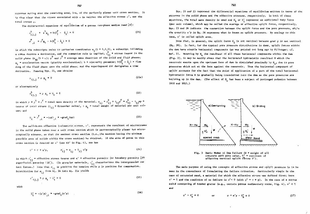
Note that, in general, the uplift force Ui 1s not vertical because grad p is not vertical
(Eq. 26). In fact, for the typical pore pressure distributions in dams, uplift forces within
the dam have sizable horizontal components (as was pOinted out long ago by Fillunger; cf.
Ref. 3). Denoting by Hu the resultant of all these horizontal components within the dam
(Fig. 3), it may be easily shown that the horizontal hydrostatic resultant H which the
reservoir exerts upon the upstream face of dam is diminished precisely by Hu ' due to pore
pressures which act at the face against the reservoir. Thus the horizontal component of
uplift accounts for the fact that the point of application of a part of the total horizontal
hydrostatic force H 1s gradually being transferred into the dam as the pore pressures are
building up in the dam. (The effect of Hu has been a subject of prolonged polemics between
1910 and 1935.)
H- Hu
/ I
opened crock
b) Sliding
H-Hu
shear bond
Fig. 3 BaSic Modes of Dam Failure (W = weight of all concrete with pore water, Vi - resultant of effective vertical uplift f~rces U').
The main purpose of using the concepts of effective stress and uplift pressure is to be
seen in the convenience of formulating the failure criterion. Particularly simple is the
case of saturated sand, s material for which the effective stress was defined first; here
n' - 1 and the condition of no failure is a'~ 0 (with cr' = a + pl. In the case of a porous
solid consisting of bonded grains (e.g., certain porous sedimentary rocks, Fig. 4), n' < 1
and
or IT + n'p - fb ~ a (27)

794
where fb = strength parameter characterizing the strength of intergranular bondsQ However,
this condition, in contrast with that for sand (n' ~ 1), is no longer exact, because fb in
general depends, in an unknown manner, Ion p. For example, p affects the lateral stress in
the material of intergranular joints (Fig~ 4) and this in turn must affect their strength,
£b' although possibly to a small degree. Most generally, for any porous material, the (volu
metric) condition of no failure may be written as
(28)
where n' is also a function of p. When this is the case, it is of no help to introduce the
effective stress. Either function Fl or function F2 must be determined experimentally and
neither way is simpler than the other.
Non-saturated Concrete.
In non-saturated concrete the fluid consists of air with water vapor, capillary water,
and adsorbed water. (Properly, the material should be treated as a multiphase system.)
The pore pressure is negative, i.e8 a tension, whose magnitude is very large (of the order
of hundreds of atmospheres) and results in a compression of the solid microstructure,
which is known as shrinkage (instantaneous shrinkage [5J). Since the effect of pore pressure
is accounted for in terms of shrinkage, it would be an incorrect duplication if body forces
Ui and pore pressures p' (negative "uplift") were considered together with the corresponding
effective stress a'. In fact, according to the theorem of equivalence of inelastic strains
and body forces (body force analogy, see Sec. 5.4 of Ref. 5), the effect of a change in body
forces U~ is equivalent to the effect of the shrinkage increments.
In non~saturated concrete, the situation is of the type described by Eq. 2B. The effec
tive area for the (negative) pressure in capillary water and adsorbed water is strongly
dependent on the pressure itself, the resultant is further affected by (positive) disjoining
pressures in hindered adsorbed layers, and the strength of interparticle bonds depends on
the degree of water saturation in the long narrow gaps between the gel particles (Fig. 6).
Thus, it is clear that the effective stress would be a useless concept for non-saturated con-
crete.
Saturated Concrete~
To decide whether or not the effective stress concept is useful for saturated concrete,
it is necessary to answer the question: Is the effective area n' and the strength of inter
particle bonds fb in cement paste strongly dependent upon pore pressure p? Lacking direct
observations, this question must be answered by deductive reasoning. As long as the devia
toric deformations of concrete remain so small that no appreciable microcracking and volume
expansion is produced, the geometry, volume, and surface area of pores filled by water, as
well as the microstructure of interparticle bonds and the numbers of water molecules in
hindered adsorbed layers,do not change significantly. In such a case, n' and f~ in Eq.
28 should be apprOXimately constant and the effective stress concept should be applicable,
in ~n approximate sense.
If the overturning failure of a dam is considered, the critical stresses are tensile
rather than shearing. When overturning is imminent, concrete is on the verge of tensile
failure. This is a type of failure which occurs almost abruptly, with hardly any prior
microcracking and volume expansion. Therefore, n' and fb should be constant up to the failure
795
initiation and the effective stress concept should be applicableo
On the other hand, in the case of sliding failure of a dam, formation of a shear band
with e~tensive microcracking causing volume expansion must precede failure (Fig. 2). The
increase in pore space alters n' as well as f b- At the same time, an immediate drop in
pore pressure is produced and possibly even an unsaturated condition (suction) is created.
In spite of an increase in n', the drop in pore pressure would normally reduce the uplift
pressure and thus tend to stabilize the material, i.e~ stop the shear failure. The saturated
condition and the original water pressure is restored only after enough water has been able
to seep into the newly created microcracks, which requires considerable time~ Theretore,
a single short-duration load, such as a Single earthquake, is less likely to produce sliding
than is the hydrostatic pressure on the upstream face (and this should be reflected in safety
factors). After the original pore pressure has been restored, the uplift is larger than before
microcracking and the shear failure is likely to continue. Obviously, the concept of effective
stress does not suffice to treat the sliding failure, and triaxial stress-strain relations
which are valid up to failure and include the pore pressure effect must be developed (see Eqso
33-38 in the sequel).
Uplift Area.
The question of uplift area n' has been the subject of a long-lasting controversy. Two
types of experiments have been conducted to this effect:
1. Fracture produced by pore pressure (e.g. [18J);
2. Deformation produced by pore pressure (e.g. [27J);
Fracture Tests. This method of testing appears natural if one realizes that it is mainly
the value of n' at impending tensile failure which is of interest. Perhaps the most careful
uplift fracture experiments have been carried out by Leliavski [18J. Their arrangement, shown
in Fig. 4, produces a state of stress which closely resembles the conditions existing in
concrete of the dam threatened by overturning failure.
manometer
seeps out
spec. ~ l44mm
.o'!~~I---"""" g collar
'1l::';'~~~~- frC)ctu re surface
in,pressure De
sfl>el case
Fig. 4 Simplified Schematic Cross Section of Leliavski's Test Arrangement (1942, 1945) (A, = cross section of collar)

796
The specimens have been subjected to a constant axial load, F"
(which is similar to the
loading of concrete in dams) and pore ~ater pressure, p, has been slowly induced in the
specimen until tensile failure occurred. To eliminate the effect of uncertainty in the
strength, f', of concrete under test conditions, Leliavski calculated n' using two tests with
failure pressures P, and P2 under different loads F, and F2 ;
n' = (29)
which ensues by subtracting the equations n'p,A = f'A + F, and n'PaA • f'A + F2 (A = cross
section area). The values obtained by testing 95 specimens ranged between 0.85 and 1.00,
with the mean value n' - 0.91. The upper limit is certainly surprisingly high.
Leliavski reported that equality of the interior well pressure Pi to the external water
pressure Pe could never be quite achieved prior to the failure, and he therefore used in Eq.
29 the average value of pore pressure within the cross section, as calculated by formulas
for radial seepage flow. However, in the numerous discussions of Leliavski's results it
seems to have passed unnoticed that the use of average pore pressure is not the proper
assumption. The reason is that tensile fracture always occurs progressively, by propagation
of a crack, rather than simultaneously in the whole cross section. Consequently, the frac
ture must always start at the external surface of the specimen, where the pressure is
highest (p • Pe' Fig. 4). Once the fracture is initiated, the tensile stress in the remain
ing cross section is raised (because the total force is constant, assuming the opening of
the crack to be negligibly small). Hence, the crack can propagate further, unless the pore
pressure ahead of the crack drops too fast, which seems not to have been the case. Apparently,
this progressive nature of fracture has been ignored in all the literature on uplift. In
the light of the foregoing discussion, Eq. 29 requires the use of the external pressure
p _ Pe rather than the average pressure in the cross section. If this had been done,
Leliavski would have obtained smaller values of n' than he did. Unfortunately, the values
of Pe needed to recalculate n' have not been reported in Ref. 18. Part of the scatter of
test results may also be due to this fact.
Another difficulty in calculating n' stems from the fact that the pressure difference
Pe-Pi must have also some effect on the tensile strength f'. The effect would be vanishing
only if Pe equalled Pi (because uniform hydrostatic pressure in the pores is known to have
no effect on strength [19, 18]). However, a radial gradient of p produces radial loads (Eq.26).
and so concrete in the core of cross section behaves like concrete under external confining
pressure (equal Pe-Pi)' This must have some, though little known and erratic, effect on ten
sile fracture. Leliavski's tests have been criticized for the fact that the n'-value may not indicate
the true effective porosity of crack-free concrete, but the effective porosity at the final
stage of failure, in which n' is possibly increased by cracking. However, considering the
tensile brittleness of concrete (lack of significant microcracking prior to failure), this
criticism does not appear to be too serious. To explain it in more detail, consider the
increase in pore space (and n') as the tensile crack begins to propagate. At that moment,
the pore pressure drops and crack propagation stops. Subsequently, however, it builds up
again and as soon as the original value of n'p is atained, which happens at lower p than
before, the failure inevitably continues because concrete in tension does not exhibit strain-
797
~rdening, i.e., cracking cannot proceed gradually at increasing strain (in contrast to
eempression tests). Hence, the original value of n'p at which the cracking started cannot
.. exceeded at the later stages of failure, which means that the failure test data should
lead to the proper value of n' (provided the peak value of pore pressure is used if any
'rop of p at the end of test is recorded).
~ormation Tests. In view of the possibility that the effective porosity, n', depends
Oft the tensile stress level, as well as for the purpose of allowable stress design, determina
tion of n' by measuring strain due to pore pressure in the elastic range has been attempted
[27, 19, II, 28, 14J. It will be shown herein, however, that a realistic estimation of n'
Oft the basis of deformation tests is impossible (unless a complete two-phase medium theory
were developed). To this end, consider Fig. 5(b). The idea is to calculate from strain e
the effective volumetric stress, 0 ' , in the solid phase of the material, using the known
bulk modulus K of the material. Then, knowing 0' and pore pressure p, it is thought that n'
could be calculated from the relation 0' D 0 + n'p.
(0)
Ib)
(10)
6t
+ = +~ ~*= ~+ p d'=d+n'p
(1 b) (20)
Fig. 5 Idealized Cross Section of a Jointed Gran~lar Material. (a) Cross sections defining a (AA') and 0' (BB'); (b) Two of the possible decomposition of total stress o. (This figure does not represent concrete)
(2b)
rhis line of thought tacitly implies the assumption that the stress state a can be decom
~sed in two stress states, exemplified by states 2a and 2b in Fig. 5, of which only one
state, 2b, contributes appreciably to the overall deformation, e, of the porous solid,
while the other state, 2a, contributes negligibly to the deformation. However, the stress

798
state a can be also decomposed in other ways, and one alternative decomposition is shown
by states la and lb. In the case la, grain ~ is subjected to pressure p on all of its
boundary, and thus the material of the grain must be in a purely volumetric state of stress,
i.e. free of shear stresses. ~In the case 2b, grain ~ is not loaded by p over all its sur
face and is not in a purely volumetric state of stress, so that shear stresses must also
exist within the grain. These tend to be concentrated near interparticle joints, which
should lead to a considerably larger overall strain of the porous solid than does the purely
volumetric stress state in the grains. It is generally true of most poroua materials that
their overall volumetric deformation is mostly due to l~calized microscopic shear stresses
within the microstructure and the volume compressibility of the solid matter forming the
porous material is usually much less than the volume compressibility of the porous material
on the whole. It is hard to check this condition for concrete because the volume compressi
bility of cement gel particles is not known. However, concrete is probably an extreme case
for which the difference between the two compressibilities is small, due to the fact that
cement gel particles are bonded across hindered adsorbed water layers. Nevertheless, among
cases la and 2a, it should be case la which leads to smaller overall deformation of the
porous solid. In any event, case 2b (with 0' = 0 + n'p), implied in the analyses thus far,
is not closer to reality than case lb. The reality should be between cases lb and 2b,
probably closer to case lb. In consequences of these facts, the volumetric strain € due
to pore pressure p and applied total stress a may be best approximated as
€ "" o*/3K with a* "" 0 + p (30)
where K m bulk modulus of concrete at constant p.
Eq. 30 does not contain n', and so n' cannot be evaluated from test data on deformation
e produced by pore pressure, unless a more accurate equation is deduced. Nevertheless, the
deformation tests are useful for determining the value of o€/Op which is requisite for
calculating the strains and stresses in the dam due to pore pressures. In Ref. 8 (Eq. 55),
it has been demonstrated that for sand (n' ~ 1) the coefficient o€/op at constant total
stress a very nearly equals 11K, the bulk compressibility of the saturated sand. Based
on the preceding consideration relative to Fig. 5(b), O€/Op should not be much different
when n' < 1. Thus, it is the fact that O€/op is nearly independent of n' which makes it
impossible to reliably determine n' from deformation tests.
In the light of the foregoing discussion, it is not surprising that the scatter of the
n'-values obtained from deformation tests has been large, despite greatest care. Some
of the calculated values [27, 19, II, 28, 14] have even exceeded 1.0, some have been much
less than 1.0, and frequently they were close to 1.0 [28J.
The stress state decomposition in Fig. 5 may also be considered in failure analysis. It
is well known [18J that concrete (as well as rocks) has the same strength when the specimen
is submerged under water of pressure p, provided pore pressure also reaches p. Here, case
la (Fig. 5) is that which indicates the stress state prior to applying axial load under
water, and indeed, this stress state can have no effect on failure because the grains are i~ a volumetric state of stress and the joints are stress-free.
Conclusions from Cement Paste Microstructure. The fracture surfaces in dam concretes
are known to hardly ever pass through the aggregate. Therefore, the effective stress and
uplift in concrete is the same as in cement paste. Powers [25J analyzed the chemical bond-
799
Idealized Schematic Microstructure of Hardened Portland Cement Paste; a • free adsorbed water molecules, Ca = calcium ions (crosses), c = remaining anhydrous cement, ch - calcium hydroxide, d - hindered adsorbed water molecules, f - fracture surface, g - cement gel (lines represent sheets of calcium silicate hydrates), i - interlayer water, m - capillary meniscus, 0 -
original surface of unhydrous cement grains, p - capillary pore, v - water vapor and air, w - capillary (liquid) water. Water molecules and calcium ions are not shRWn everywhere they exist. Width of picture ~ 30 ~m. Spacing of sheets (-30 A) relative to length of sheets is about 100-times exaggerated.
(0 )
(b)
Fig. 7
fracture surface Ap
x
f
Ap o 00
DODXDDXXXOOXXO
o water molecules x Ca- ions
(a)-(b) Example of the Fracture Surface in Hardened Cement Paste (cf. Fig. 6), (c) Hindered Adsorbed Water Layer

800
ing of gel particles in cement paste. Considering the particles to be spheroidal with about
12 monoatomic chemical bonds, and taking into account the average size of gel particles,
he concluded that the bonded surface area of each particle is only about 0.2 percent of the
total surface area, leaving thus 0.988 of the surface area accessible to water. However,
it seems to have been overlooked thus far that this result does not imply that n' = 0.998.
This is due to the fact that anisotropic, rather than isotropic (hydrostatic), states of
stress must exist in all pores whose thickness ! is less than ten molecular diameters
(26.3 x 10⁻¹⁰ m). These pores represent what is known as hindered adsorbed water layers
[5J and include both the physically adsorbed water and the inter layer water ( d and i in
Fig. 6). Consider the hindered adsorbed layer in Fig. 7(c). As soon as the pressure p of
water in an adjacent macropore (capillary pore) is raised, water molecules begin migr.ating
along the solid surface into the adsorbed layer until a constant value of Gibb's free
energy ~ throughout the layer is reached. At constant temperature, the attainment of constant
~ means that the spreading pressure, ITd
, of water molecules is such that the average longi
tudinal pressure p in the layer (p = nd/t) is constant (see Eqs. 18, 22 and 29 or Ref. 4).
Adsorbed water molecules are not freely mobile in all directions, unlike those in liquid
(capillary) water. Their movement is completely restricted in the direction normal to the
layer and is also largely restricted within the plane of the layer (especially in the first
molecular layer), due to the periodicity of the potential of adsorption forces at the solid
surface. By virtue of this fact, water in the hindered adsorbed water layer resembles more
a solid than a liquid, especially in the transverse direction. Hence, the state of (average)
stress in the layer need not be hydrostatic. In particular, if pressure increment ~p is a
applied in the directions of the surface (Fig. 7(c», the increment 6pd of Pd (called dis
joining pressure) must be less than np, as it would be in a solid; hence hpd = Vl~p where
VI < 1 is a parameter analogous to Poisson's ratio of solids and depending on the thickness
L of the layer.
A significant portion of the fracture surface through cement gel is likely to pass
along hindered adsorbed water layers; see Fig. 7(a). On this portion, the pressures acting
on the surface just prior to fracture are 6pd = Vf~p. The condition of static equivalence
of macroscopic and microscopic stresses acting on the failure surface yields 6cr = ~' - nc p
- In v'Pd COS" dA' (Fig. 7(b» where n = portion of the sinuous fracture surface (f-f in d c
Fig. 6) passing through capillary water and nd = portion passing along hindered adsorbed
layer; dA I = microscopic area element of the sinuous fracture surface and ~ = its angle with
the macroscopic fracture plane. Obvi rus ly nc + nd < 1; probably nc + nd is quite close to
unity. Substituting 6a = 6cr' - n'~p(Eq. 24), it follows
in which dA
with v'av nd = S v' (./,) dA
nd
(31)
dA' cosa = area element of macroscopic fracture plane; t = function of coordi-
nates x and y on this plane; and v'av = average value of Vi for the hindered adsorbed layers.
Because v'av < 1, a typical value being perhaps 0.6, it becomes clear that the uplift area
n' must be substantially smaller than one, even if most of the fracture surface passes through
water (as Powers assumed). This is, of course, true only for uninjured cement paste and
concrete. Eq. (31) may allow a quantitative estimate of n' if a sufficient quantitative know-
801
ledge of the microstructure of cement paste is attained.
The migration of water molecules into the hindered adsorbed water layers is a slow
process. The changes 6Pd in disjoining pressure Pd occur with a substantial delay after
the change ~ of pressure p in the capillary pores. Thus, at the instant the change 6p
occurs, the uplift area n I for that change is only nc ,and the va 1ue of n' indicated by Eq.
31 is approached only after a certain time. This time should be about the same as the lag
of the delayed component of shrinkage behind the change in pore humidity, and this suggests
a delay of a few months. This delay is not large as compared with the time needed for the
pressure to penetrate the concrete of the dam, but may be large in case of laboratory tests.
TRIAXIAL STRESS-STRAIN RELATIONS AND FAILURE ANALYSIS The failure
the knowledge of
When the effect
in the form
analysis of a dam, especially analysis of the sliding failure, requires
realistic non-linear triaxial stress-strain relations of the material.
of pore pressure is negligible, these relations may be in general written
de~' . ~J
de da 3K + dA (32 )
in which Sij = a iJ, - 6iJ.o = deviator of stress tensor 0 'd ij' e ij = eij - Bije = deviator of
strain tensor €ij; deij = deviatoric inelastic strain increments, dA = inelastic dilatancy
[6, 7J (resulting from deviatoric strains). The time-dependent strains (creep and shrink
age) as well as thermal strains, are not considered herein.
When pore pressure changes are important, a rigorous approach requires a two-phase
medium model (Eq. 39 in the sequel). However, the one-phase medium model (Eq. 32) may
still be used as a simple approximation. For this purpose, it is necessary to decide whether a should remain in Eq. 32 or be 1 d b rep ace y a + p or a + n'p, and also which type of stress should be used in calculating d R 11 A· eca ing the discussion that has led to Eq. 30, the most appropriate formulation appears to be as follows:
ds .. de"'J. = ~ + de"
~ 2G ij da*
de = 3K + dA + ~dp, with a* a+p (33)
in which 0*, the effective stress for n' = 1, is used to determine the elastic strains
(same as for sands; see Eq. 19 of Ref. 14); and C = be/bP at constant a*, as determined
by tests of deformation due to pore pressure. The inelastic strains also depend on volu-metric stress e HCN'eve' h
r, 1nasmuc as the inelastic strains are due to microcracking, de" and
dA ought to be determined with the help of the effective stress cr' = a + n'p (rather t~n 0*) because this stress governs fracture. A specific formulation will be given in the Bequel.
Formulation of the stress-strain relations for concrete ( with negligible pore pres-sures) has recently been intensely stud{ed. A Ii
~ pp cations of the theories of plasticity and hypoelasticity have met with a limited
success. However, an entirely new formulation, called endochronic theory, was proposed in 1974 for concrete [ 6, 7J. In this formulation, the accumulation f d d o amage ue to microcracking is described by means of the variable, ~, defined as
(34)

802
and the inelastic strain increments, in the special case of
are expressed as
-~ de1j - 2G dz, = ..i.'!l.... dz f (T) I
dT) = F(eij
,a) dE;,
G = G(A), K = K(A)
time-independent formulation,
(35 )
(36)
(37)
Here z = intrinsic time; f, F, Fi = isotropic functions which must be determined experiment
ally; and G, K a incremental shear modulus and bulk modulus, which both depend on dilatancy
A (due to microcracking). It has been demonstrated [7J that virtually all known basic
behavior of concrete (stress-strain curves and failure data for compression, tension,
biaxial and triaxial tests, lateral strains, volume change, torsion with compression,
unloading, cyclic loading, spirally reinforced and spirally prestressed concrete) can be
adequately modeled by Eqs. 32 and 34-37.
For an approximate extension of the endochronic stress-strain law to the case of large
pore pressures, Eq. 32 is replaced by Eq. 33, as has already been mentioned. Furthermore,
stress a appearing in the argument of functions F and F, should be replaced not by a* but
by oJ = cr + nip because cr in these two functions describes the effect of confining pressure
on microcrack1ng, which is a fracture-type phenomenon and thus depends mainly on a', accord
ing to Eq. 27. Hence, an approximate extension of the endochronic law to large pore pres
sures also requires that Eq. 36 be replaced by
with cr' ~ a + n'p (38)
In a rigorous formulation, the concept of an inelastic two-phase medium must be used.
In this concept, which has already been developed for saturated sands [8J, the volumetric
stress-strain relation from Eq. 33 must be replaced by the relations
(39)
d/ a c", daS + Ca. daF
- kd)'
in which e.S , eF _ strains in solid and fluid; as, of ::II; the associated stresses in solid
and fluid (Eq. 20); C"
, C, ., C."
C •• - elastic compressibilities (C, •• Cal); k =
experimental coefficient characterizing the strain of fluid which is necessary to allow
the inelastic strain of solid, dA, to occur at constant as and aF. Eq. 39 cannot be
practically used as yet, because the values of Cll' C12 ' C21 ' C22 and k are not known.
There are several other material properties that are of interest for the analysis of
gravity dams, but are beyond the scope of this parer. These include: effects of creep,
shrinkage, and hydration heat on the stresses and cracking; and propagation of cracks
across the dam, with the influence of temporary pore suction caused by volume increase
near the tip of crack. One particularly noteworthy difficulty in analyzing the crack
propagation is the fact that, OWing to the very large size of dams relative to the size
of aggregate, a singular stress field can develop near the crack tip (around a small zone
of microcracking). Another facet of this phenomenon is the unstable strain localization
(material instability) when tangent moduli become very small (as it happens on approach
to failure). This phenomenon cannot occur on a scale that is not sufficiently large as com-
803
pared with the size of aggregate, and is insig~ificant in ordinary-size reinforced concrete
structures, whereas in structures as large as dams this phenomenon should be of importance.
The usual finite element method cannot account for this effect, unless the size of finite
elements does not exceed about 20-times the size of aggregate, which is an impossibly small
limit for the analysis of a dam. Special methods will have to be developed for this purpose
if the analysis up to failure (e.g., sliding failure) should yield realistic results.
C ooCLUS I OOS
1. In an ideal dam, which is free of cracks, the rate of penetration of hydraulic
overpressure p into concrete is extremely slow. This is due to the water deficiency of
concrete which is caused by hydration (self-desiccation), and even more, by air-entrain
ment. Only about ~ thickness of a large ideal dam can be penetrated within 100 years,
the rest remaining unsaturated. (In a real dam, the spacing and width of continuous
cracks through the dam, whether in concrete or in construction joints, and the type of
drainage normally dominate the rate of saturation of concrete within the dam.)
2. Drying from the downstream face is even slower and normally cannot penetrate
deeper than a few meters into an ideal dam within a 100-year time span. When saturated
cracks extend to the downstream face, the penetration of drying is still much smaller.
Therefore, drying has a relatively small effect on uplift distribution and shrinkage
stresses in the dam are small, except near the face (and near construction jOints, due
to drying during construction).
3. It is shown that the water deficiency, which is continuously being created by
hydration, must be included in the linear diffusion equation governing pore pressures in
saturated concrete. This effect substantially reduces pore pressures and may often cause
unsaturated condition. The movement of saturation boundary complicates solution, but
approximately a water sink equivalent to terminal water deficiency of concrete may be
assumed to exist at the moving saturation boundary. More accurately, water diffusion in
non-saturated concrete ahead of the saturation boundary is to be conSidered, with a proper
interface condition (Eq. 18).
4. When diffusivity C of saturated concrete is calculated from its permeability c,
the value of compressibility ~ which relates C to c (Eq. 4) must take into account:
(1) the fact that only the volume change of capillsry water ahould be included in ~,
while the hindered adsorbed water forms essentially part of the solid structure and should
not be included; (2) the dilation of pore space due to deformation of solid under pore
pressure.
5. Although the diffusivity C'in non-saturated concrete is strongly dependent on
pore humidity (Eq. 13), most of the mass of the dam (downstream surface layer excepted)
falls into the region of constant C~ in view of the high pore humidities after self
deSiccation.
6. Despite the fact that over 99% of the weakest microscopically sinuous cross section
of concrete passes through water, the effective uplift area n' must be distinctly less than
1.0. This ensues from the fact that the transverse pressure which is induced in hindered
adsorbed water layers by the pressure 6p in capillary pores must be substantially less than
6p, due to the non-liquid nature of adsorbed water layers. A reasonable estimate seems to
be n' - 0.9 when safety against tensile fracture is analyzed.

804
7. Tests of deformation due to pore pressure cannot yield the value of effective
uplift area n') unless a two-phase medium model is developed for concrete. Among the
simplified assessments of the effective uplift area for deformation analysis (Fig. 5 ),
1.0 is the most reasonable value.
8. At the present level of knowledge, only failure tests are useful for determining
the uplift area~ In their evaluation, it is necessary to take into account the progressive
nature of fracture when there is pressure gradient along the fracture surface.
9. No "negative" uplift should be introduced due to gradients of pore tensions in
drying concrete. This effect is accounted for by including shrinkage strains in the analy
sis.
10. In the range of confining pressures within dams, concrete cannot fail by shear
(sliding) without prior volume expansion due to microcracking. For this reason, the uplift
area determined from tests of failure due to pore pressure is of no relevance for shear
failures, in contrast to overturning failure. When the safety against shear (sliding)
failure is analyzed, the gradual development of microcracka prior to failure must be taken
into account. This means that the effective porosity n' approaches 1.0. However, the
temporary pore suction produced by volume expansion (dilatancy) due to shear (microcrack
ing), which temporarily reduces the uplift pressure, should also be considered.
11. The progressive nature (propagation) of the tensile fracture (overturning failure),
as well as the shear fracture (sliding failure), should be considered in an accurate analy
sis.
12. To extend the nonlinear incremental triaxial stress-strain relations for concrete
to the case of large pore pressures, one may, as an approximation, replace the volumetric
stress increments in concrete by the effective stress for the effective porosity 1.0.
However, the total (non-incremental) volumetric stress appearing in the expressions for
inelastic deviator strains and dilatancy should be replaced by the effective stress for the
actual effective porosity n' (n' ~ 0.9). The deformations due to pore pressure changes
represent an additional term in the stress-strain relation. For a rigorous formulation, a
two-phase medium formulation would have to be verified experimentally.
Conclusions 1# 2, 5, and 9-11 summarize the facts already in essence known. Con
clusions 3, 4, 6-8, and 12 are based on the present analysis.
ACknowledgement.
The support of the U.S. National Science Foundation under Grant GK~26030 is gratefully
apprec ia ted.
REFERENCES
1. Aleksandrovskii, S. V., "Analysis of Plain and Reinforced Concrete Structures for Tempperature and Moisture Changes with Account of Creep" (in Russian), 2nd Ed., Stroyizdat, Moscow, 1973 (Chpt. II).
2. Bdant, Z.P., Najjar, L.J., ''Drying of Concrete as a Nonlinear Diffusion Problem," Cement & Concrete Research, Vol. 1, 1971, pp. 46l~473.
3. Bafant, Z.P., Najjar, L.J., '~onlinear Water Diffusion in Nonsaturated Concrete," Materials and Structures (RlLEM, Paris), Vol. 5, 1972, pp. 3~20.
4. Baiant, Z.P., 'Thermodynamics of Interacting Continua wi~h Surfaces," ~ Engineering and Design," Vol. 20, 1972, pp. 477~505.
5.
6.
7.
8.
805
Ba~ant, Z.P., '7heory of Creep and Shrinkage in Concrete Structures! A Pr~cis of Recent Developments," Mechanics Today, Vol. 2, pp. 1-93, Pergamon Press, 1975.
Ba~ant, Z.P., itA New Approach to Inelasticity and Failure of Concrete, Sand and Rock: Endochronic Theory," Proc.,Soc. of Engng. Science 11th Annual Meeting, G.J. Dvorak, Ed., Duke University, Durham, N.C., Nov. 1974, pp. 158-159.
Bazant, Z.P., "Endochronic Theory for Inelasticity and Failure of Concrete," submitted to Proc. ASeE, J. Eng. Mech. Div.
Ba~ant, Z.P., Krizek, R.J., "Saturated Sand as an Inelastic Two-Phase Medium," ~. Mech. Div., Proc. ASCE, Vol. 101, 1975 (in press).
9. Blot, M.A., ''rheory of Propagation of Elastic waves in a Fluid-Saturated Porous Solid," J. of the Acoustical Soc. of Am., Vol. 28, 1956, pp. 168-191.
10.
11.
12.
13.
14.
15.
16.
17.
18.
19.
20.
Bhatnagar, P.S., Kapla, I.P., Sharma, R.P., "Structural Behavior of Bhakra Dam, Int. Carom. on Large Dams, 9th Congress, Instanbul, 1967, Vol. III, pp. 245-274.
Carlson, W., Davis, R.E., Discussion, Proc. ASCE, Vol. 74, 1948, p. 1532.
Carlson, R.W., "Permeability, Pore Pressure, and Uplift in Gravity Dams," !!.!!!:.s. ASME, Vol. 122, 1957, pp. 587~613.
Crank, J., Mathematics of Diffusion, OKford University Press, London 1957.
Fillunger, P., 'Versuche uber die Zugfestigkeit bei allseitigen Wasserdruck," ~ Wochenschrift fur den Offentl. Baudienst, Vol. 29, 1915, p. 443.
Italian Subcommittee for Observations of Dams, "Dam Measurements in Italy," Int. Lomm. on Large Dams, 8th Congress, Edinburgh, 1964, Vol. 2, pp. 684~686. -
Joint ASCE-USCOLD Committee On Design, ''Design Criteria for Large Dams," ASCE, New York, 1967, p. 92 and p. 97 (see also '~inal Report of the Subcommittee on Uplift in Masonry Dams," ASCE Separate No. 133, and Trans. ASCE, Vol. 117, 1952, p. 1218).
Lacy, F.P., Schoick, G.L.V., ''r.V.A. Concrete Gravity Dams Uplift Observations and Remedial Measures ,II Int. Conn. on Large Dams, 9th Congress, Ins tanbu I , 1967, vol. 1, 487-507.
Leliavski S., Uplift in Gravity Dams, Constable & Co. Ltd., London 1958; see also Trans. AseE, Vol. 112, 1947, pp. 444-487; and a summary in: N.S. Attri, .. Uplift in Gravity Dams," J. Struct. Div., Proc. ASCE, Vol. 93, 1967, pp. 61-68.
McHenry, D., ''The Effect of Uplift Pressure on the Shearing Strength of Concrete," 3rd Congress, Int. Comm. on Large Dams, Stockholm, 1948, Vol. I, R. 48.
Mather, B., I~se of Low Portland Cement Content in Construction of Dams," ~. Concrete Institute, Vol. 71, 1974, pp. 589-599.
21. Murata, J., ''Studies of the Permeability of Concrete," Bulletin RlIEM (Paris) No. 29, Dec. 1965, pp. 47-54.
22.
23.
24.
25.
26.
Nicol, T.B., et.al., ''Deterioration Problems at Avon Dam," Int. Comma on Large Dams, 9th Congress, Istanbul, 1967, Vol. III, p. 716.
Powers, T.C., irA Discussion of Cement Hydration in Relation to the Curing of Concrete," Proc. of the Highway Research Board, Vol. 27, 1947, pp. 178-188 (also PCA Bull. 25).
Powers, T.C., Copeland, L.E., Hayes, J.C., Mann, H.M., "Permeability of Portland Cement Paste," J. Am. Concrete Inst., Vol. 51, 1954, pp. 285-298 (also PCA Bull. 53).
Powers, T.C., ''Hydraulic Pressure in Concrete," Proc. Am. Soc. of Civil Engrs., Vol. 81, July 1955, Paper 742 (also PCA Bull. 63).
Rhodes, J .A., ''Structural Behavior Measurements on Concrete Gravity Dams," Int. Comm. on Large Dams, 8th Congress, held in Edinburgh, 1964, Vol. II, pp. 125-142.

806
27. Serafim, J.L., liThe 'Uplift Area' in Plain Concrete in the Elastic Range," Int. Comm .. on Large Dams, 8th Congress, held in Edinburgh, 1964, Vol. 5, Comm. 17, pp. 599-622; also: "Deformations du b4ton dues aux press ions dans les pores," Bull. RILEM, No. 27, 1965, pp. 73-76.
28. Terzaghi, K., "Simple Tests to Determine Hydrostatic Uplift," Engng. News Record, June 18, 1936, p. 872.
29. Terzaghi, K., ''Stress Conditions for the Failure of Concrete and Rock, II Proc. ASTM, Vol. 45, 1945, p. 777.
30. Wierig, H.J., 'Die Wasserdampfdurchlassigkeit von Zementm~rte1 und Beton,"~Kalk-Gips, 1965, No.9, pp. 471-482.
31. Zienkiewicz, "Stress Analysis of Hydraulic Structures Including Pore Pressure Effects, II Water Power (London), Vol. 15, No.3, March 1963.
APPENDIX I - NUMERICAL ANALYSIS OF WATER DIFFUSICN IN DAMS
To develop a finite element program covering water diffusion in both saturated and
non-saturated concrete, it is advantageous to put the governing differential equations for
each of these two cases into a common form. This form reads
J = -A grad X, B.ll! - H' /It
-div :!, (40)
in which X is the unknown field variable; A and B - given-coefficients, and H' = H'(t)
given function of time. As can be easily verified, Eqs. 40 reduce to Eqs. 11 and 12 for
x < 0 and to Eqs. 2 and 3b for X ~ 0, if the follOWing definitions aq' introduced:
I c' m.! bh
for X < 0: X - h-l, A-C ' , B= k == C" H' __ s
k bt (41)
for X ~ 0: X = p, A == Pw c 8w ,B (42)
The interface condition for the saturation boundary (Eq. 18) is automatically satisfied.
The boundary conditions at the upstream and downstream faces of the dam consist in a pre
scribed value of X, while on the foundation surface the normal component of grad t either is
zero or is continuous across the surface.
The finite element formulation for equations of the type 40 is well known. Eq. 40
has the advantage that a single type of finite element covers both saturated and unsaturated
condition. Also, restricting the saturation boundary to lie on the element boundary, the
interface condit"ion (Eq. 18) is automatically satisfied by the finite element formu lation.
Time integration is carried out in steps and several iterations are necessary at each step
to determine whether A, B, and F' should be computed from Eq. 42 or Eq.43.
The effect of temperature gradients (due to hydration heat) upon moisture diffusion
ought to be also considered if an accurate prediction of early pore pressure development is
desired. This problem is beyond the scope of this study.
807
APPEND IX II - BAS IC N(JrATIONS
c, c', c* - permeability coefficients in Eqs. 2, 11, and 1;
C, co. - diffusivity of saturated and non-saturated concrete (Eqs. 4, 12, 13);
C~ = value of C' at saturation;
8w = specific weight of liquid water;
h = relative humidity in the pores;
hs = h produced by self-desiccation at constant w (Eq. 12)
~ s vector of the mass flux of water in concrete;
k inverse slope of desorption or adsorption isotherm (Eq. 16)
K = bulk modulus of concrete (Eq. 30);
n, n' • volumetric porosity and effective poro.ity (Eqs. 20, 24);
p = pressure in capillary pores (in excess of one atmosphere);
Po = value of p at the boundary;
t = time;
Ui
, UI - uplift body forces (Eqs. 23, 26);
w, w c masses of capillary water and of all water per TIi' of concrete;
wh
c water deficiency produced by hydration (Eq. 3b);
x, y or Xi - cartesian spatial coordinates (i = 1, 2, 3);
~, ~w • compressibilities of pore water phase and of liquid water as such;
€ij' € - strain tensor and volumetric strain;
~ = Gibbs' free energy per unit mass of pore water;
p = mass density of liquid water; pF, pS, P - bulk mass densities of the fluid phase, solid W phase; and concrete as a whole;
Superscripts ( •• )F, ( )S refer to fluid phase and solid phase.

808
APPENDIX III - NarE AFTER SUB!USSI(I( r. MANUSCRIPT
As a reaction to several valuable comments which the writer had the privilege receive from Messrs. Bryant Mather and Roy W. 'Carbon after their glaoclll8 OV'er the manuscript, the writer wishes to co~rect one stat"'nt and expand othera.
The value of 6t as the typical air-entrainment of concrete ia unrealistic. Actually, this value is typical of the fraction of the fresh mixture which pa •• es the 1.5-inch sieve. In the full mixture with 6-inca aggregate, this corre.ponds tc roughly 3 to 3.5t air-entrainaent and thus all nUDBrical values given before relat! to air-entrainment should be corrected accordill81y. BDwever. the correctiona are 0
significant and do not change any of the conclusions.
It must be emphasized that there is no direct experillental support for the 60( fold increase in permeability on saturation, as mentioned below Sq. 19. This is merely an indirect logical inference from certal~isobted ·test data for different concretes and the e~planation in terms of microstructure below 14. 19 is merely teo tative. However, no data contradicting this inference are known either.
It should be also noted that self-desiccation slowa down hydration, which in turn slows down self-desiccation and development of water deficiency. Thus, funct! f(t) mentioned before Eq. 4 should depend not only·OI'I temperature but abo on h, wh may be done by replacing f(t) by f(t ), t being the equivalent hydration period [5 Nevertheless, except for extremely l~ wafer-cement ratios, ~he drop of pora humid! due to self-desiccation is only a few percent,which would not have much effect on f (t).
The water deficiency need not be strictly proportional to the cement content, pozzolans are present ~ecause the pozzolans might not be inert in the hydration pre The estimate of 3 kglm water deficiency before Sq. 4 may be too low, although it should be good enough for the purpose of the present analysis.
Perhaps it should be also emphasized that the overturning failure is considere only for the purpose of determining the ssfety against this failure to occur becaus even lOot uplift over the entire base cannot overturn the dam. Also, the safety against sliding failure is normally more critical.
The statement (below Eq. 30) that fracture hardly ever passes through the aggI gate is based on the experimental data (of S. Shah, G. Winter, and others) which ir cate that in low strength concretes, by contrast to high stress concretes, microcr. ing begins at the aggregate-mortar interface and then spreads into the mortar.
Errata. - In Fig. 1, change 'bnhydrous"to "anhydroua" and "cement gel" to "cement ge ;itiiOther hydration products", more accurately. In the 2nd line below Eq. 16, ins comma before w -. In Ref. 31 - insert author's initials O.C. ev