criteria for approval of category iii · pdf fileac 120-28d july 13, 1999 criteria for...
TRANSCRIPT

AC 120-28D
July 13, 1999
CRITERIA FOR APPROVAL OFCATEGORY III WEATHER MINIMA
FOR TAKEOFF, LANDING, AND ROLLOUT


07/13/99 AC 120-28D
1. Purpose. This advisory circular (AC) provides an acceptable means, but not the only means, forobtaining and maintaining approval of operations in Category III Landing Weather Minima and lowvisibility takeoff including the installation and approval of associated aircraft systems. It includesadditional Category III criteria or revised Category III criteria for use in conjunction with Head-upDisplays, satellite navigation systems, low visibility takeoff guidance systems, Wide-body Fail Passiveoperations and use of Category III during certain engine inoperative operations. This revision alsoupdates and incorporates provisions of the former AC 20-57 into AC 120-28.
This revision incorporates changes resulting from the first steps toward international all weatheroperations (AWO) criteria harmonization taken by the Federal Aviation Administration (FAA),European Joint Aviation Authorities (JAA), and several other regulatory authorities. Subsequentrevisions of this AC are planned as additional all weather operations harmonization items (AHI) areagreed and completed by FAA JAA, and other regulatory authorities.
L. Nicholas LaceyDirector, Flight Standards Service


07/13/99 AC 120-28D
i
TABLE OF CONTENTS
SEC # SECTION TITLES
1 PURPOSE
2 RELATED REFERENCES AND DEFINITIONS2.1 Related References2.2 Definitions
3 BACKGROUND3.1 Major Changes Addressed in this Revision3.2 Relationship of Operational Authorizations for Category III and Airborne System
Demonstrations3.3 Applicable Criteria
4 OPERATIONAL CONCEPTS4.1 Classification and Applicability of Minima4.2 Takeoff4.3 Landing4.3.1 Concepts and Objectives4.3.2 Fail Operational Category III Operations4.3.3 Alert Height4.3.4 Fail Passive Category III Operations4.3.5 Decision Altitude (Height)4.3.6 Go-Around Safety4.3.7 Category IIIa4.3.8 Category IIIb4.3.9 Runway Field-Length4.3.10 Landing System Sensors (NAVAIDs) and Aircraft Position Determination4.3.10.1 Instrument Landing System(ILS)4.3.10.2 Microwave Landing System (MLS)4.3.10.3 GNSS Landing System (GLS)4.4 RNAV/Flight Management Systems (FMS)4.5 Required Navigation Performance (RNP)4.5.1 Standard RNP Types4.5.2 Non-Standard RNP Types4.6 Flight Path Definition4.7 Engine Inoperative Category III Capability
5 AIRBORNE SYSTEMS5.1 General5.1.1 Airborne Systems5.1.2 Non-Airborne Systems5.1.3 Takeoff Guidance Systems5.2 Airborne Systems for Category III Minima Not Less Than RVR6005.3 Airborne Systems for Category III Minima Less Than RVR6005.3.1 Airborne Systems for Category III Minima Not Less Than RVR400

AC 120-28D 07/13/99
ii
5.3.2 Airborne Systems for Category III Minima Not Less Than RVR300 (75 m)5.3.3 Airborne Systems for Category III Minima Less Than RVR3005.4 Automatic Flight Control Systems and Automatic Landing Systems5.5 Flight Director Systems5.6 Head-up Display Systems5.7 Enhanced/Synthetic Vision Systems5.8 Hybrid Systems5.9 Instruments and Displays5.10 Annunciations5.11 Automatic Aural Alerts5.12 Navigation Sensors5.13 Supporting Systems and Capabilities5.13.1 Flight Deck Visibility5.13.2 Rain and Ice Removal5.13.3 Miscellaneous Systems5.14 Go-Around Capability5.15 Excessive Deviation Alerting5.16 Rollout Deceleration Systems or Procedures for Category III5.16.1 Stopping Means5.16.2 Antiskid Systems5.17 Engine Inoperative Category III Capability5.18 Airborne System Assessment for Irregular Pre-Threshold Terrain5.19 Airworthiness Demonstrations of Airborne System Capability for Category III
6 PROCEDURES6.1 Operational Procedures6.1.1 Application of AFM Provisions6.1.2 Crew Coordination6.1.3 Monitoring6.1.4 Use of the Decision Height or Alert Height6.1.5 Call-outs6.1.6 Aircraft Configurations6.1.7 Compatibility with Category I and Category II Procedures6.1.8 Flight Crew Response to Non-Normal Events6.2 Category III Instrument Approach Procedures and Low Visibility Takeoff6.2.1 Takeoff Guidance System Procedures6.2.2 Acceptable Procedures for Category III Approach6.2.3 Standard Obstacle Clearance for Approach and Missed Approach6.2.4 Special Obstacle Criteria6.2.5 Irregular Terrain Airports6.2.6 Airport Surface Depiction for Category III Operations6.2.7 Continuing Category III Approaches in Deteriorating Weather Conditions6.2.8 Low Visibility Taxi Procedures6.2.9 Navigation Reference Datum Compatibility (e.g.,WGS-84/Other Datum)
7 TRAINING AND CREW QUALIFICATION7.1 Ground Training7.1.1 Ground System and NAVAID’s for Category III

07/13/99 AC 120-28D
iii
7.1.2 The Airborne System7.1.3 Flight Procedures and Associated Information7.2 Flight Training (Aircraft or Simulator)7.2.1 Initial Qualification7.2.2 Recurrent Qualification7.2.3 Recency of Experience7.2.4 Re-qualification7.2.5 Cockpit or Aircraft System Differences7.2.6 Category III Operations with an Inoperative Engine7.2.7 Training in Conjunction with Advanced Qualification Programs (AQP) or Exemptions for
“Single Visit Training”7.2.8 Credit for “High Limit Captains” (Reference section 121.562)7.2.9 Enhanced or Synthetic Vision Systems (Independent Landing Monitor)7.3 Checking or Evaluations7.4 Experience with Line Landings7.5 Crew Records7.6 Dual Qualification7.7 Interchange7.8 Training For Use of Foreign Airports for Category III Operations or Low Visibility Takeoff7.9 Line Checks
8 AIRPORTS, NAVIGATION FACILITIES AND METEOROLOGICAL CRITERIA8.1 Use of Standard Navigation Facilities8.2 Use of Other Navigation Facilities or Methods8.3 Lighting Systems8.4 Marking and Signs8.5 Low Visibility Surface Movement Guidance and Control (SMGC) Plans8.6 Meteorological Services and RVR Availability and Use8.6.1 Meteorological Services8.6.2 RVR Availability and Use8.6.2.1 RVR Availability8.6.2.2 RVR Use8.6.3 Pilot Assessment of Takeoff Visibility Equivalent to RVR8.7 Critical Area Protection8.8 Operational Facilities, Outages, Airport Construction, and NOTAM’s8.9 Use of Military Facilities8.10 Special Provisions for Facilities Used for ETOPS or EROPS Alternates8.11 Alternate Minima8.12 Flight Planning to Airports That Have Weather Conditions Below Landing Minima
9 CONTINUING AIRWORTHINESS/MAINTENANCE9.1 Maintenance Program9.2 Maintenance Program Provisions9.3 Initial and Recurrent Maintenance Training9.4 Test Equipment/Calibration Standards9.5 Return to Service Procedures9.6 Periodic Aircraft System Evaluations9.7 Reliability Reporting and Quality Control

AC 120-28D 07/13/99
iv
9.8 Configuration Control/System Modifications9.9 Records9.10 FAR 129 Foreign Operator Maintenance Programs9.10.1 Maintenance of FAR 129 Foreign Registered Aircraft9.10.2 Maintenance of FAR 129 Foreign Operated U.S. "N" Registered Aircraft
10 APPROVAL OF UNITED STATES OPERATORS10.1 Operations Manuals and Procedures10.2 Training Programs and Crew Qualification10.3 Flight Planning (e.g., Dispatch, MEL, Alternate Airports, ETOPS or EROPS)10.4 Formulation of Operations Specification10.5 Operational/Airworthiness Demonstrations10.5.1 Airborne System Suitability Demonstration10.5.2 "Operator Use Suitability" Demonstration10.5.2.1 Data Collection For Airborne System Demonstrations10.5.2.2 Data Analysis10.5.2.3 Approval of Landing Minima10.6 Eligible Airports and Runways10.7 Irregular Pre-Threshold Terrain and Other Restricted Runways10.8 Engine-Inoperative Operations and ETOPS or EROPS Alternates based on Category III10.8.1 General Criteria for Engine Inoperative Category III Authorization10.8.2 Engine Inoperative "Flight Planning"10.8.3 Engine Inoperative En Route10.8.4 Engine Failure During Approach, Prior to Alert Height or Decision Height10.8.5 Engine Failure After Passing Alert Height or Decision Height10.9 New Category III Operators10.10 Credit for Experienced Category III Operators for New Authorizations10.10.1 New Airports/Runways10.10.2 New or Upgraded Airborne System Capabilities10.10.3 Adding a New Category III Aircraft Type10.11 Category III Program Status Following Operator Acquisitions/Mergers10.12 Initiating New Combined Category II and Category III Programs10.13 United States Carrier Category III Operations at Foreign Airports10.14 Category III Operations on Off-Route Charters10.15 Approval of Category III Minima and Issuance of Operations Specifications10.16 Operations Specification Amendments10.17 Use of Specia l Obstacle Clearance Criteria (e.g., RNP Criteria)10.18 Proof-of-Concept Demonstration for New Systems/Methods
11 FOREIGN AIR CARRIER CATEGORY III AT UNITED STATES AIRPORTS(Part 129 OPERATIONS SPECIFICATIONS)
11.1 Use of ICAO or FAA Criteria11.1.1 Acceptable Criteria11.1.2 Foreign Operator AFM Provisions11.1.3 Foreign Operator Category III Demonstrations11.2 Issuance of Part 129 Operations Specifications11.3 Use of Certain United States Facilities

07/13/99 AC 120-28D
v
12 OPERATOR REPORTING, AND TAKING CORRECTIVE ACTIONS12.1 Operator Reporting12.2 Operator Corrective Actions
APPENDIX 1 DEFINITIONS AND ACRONYMS
APPENDIX 2 AIRWORTHINESS APPROVAL OF AIRBORNE SYSTEMS USED DURING ATAKEOFF IN LOW VISIBILITY WEATHER CONDITIONS
1 APPENDIX 2 PURPOSE
2 APPENDIX 2 GENERAL
3 APPENDIX 2 INTRODUCTION
4 APPENDIX 2 TYPES OF TAKEOFF OPERATIONS
5 APPENDIX 2 TYPES OF TAKEOFF SERVICES5.1 APPENDIX 2 ILS5.2 APPENDIX 2 MLS5.3 APPENDIX 2 GNSS [PoC]5.3.1 APPENDIX 2 GNSS Flight Path Definition [PoC]5.3.2 APPENDIX 2 GNSS Airplane Position Determination [PoC]5.4 APPENDIX 2 Other5.4.1 APPENDIX 2 Datalink [PoC]
6 APPENDIX 2 AIRWORTHINESS6.1 APPENDIX 2 General Takeoff System6.1.1 APPENDIX 2 Takeoff Performance Prior to 35 Ft. AGL6.1.1.1 APPENDIX 2 ILS6.1.1.2 APPENDIX 2 MLS6.1.2 APPENDIX 2 Workload Criteria6.2 APPENDIX 2 Takeoff System Integrity6.3 APPENDIX 2 Takeoff System Availability6.4 APPENDIX 2 Flight Deck Information, Annunciation and Alerting6.4.1 APPENDIX 2 Flight Deck Information6.4.2 APPENDIX 2 Annunciation6.4.3 APPENDIX 2 Alerting6.4.3.1 APPENDIX 2 Warnings6.4.3.2 APPENDIX 2 Cautions6.4.3.3 APPENDIX 2 Advisories6.4.3.4 APPENDIX 2 System Status6.4.3.5 APPENDIX 2 Engine Failures
7 APPENDIX 2 TAKEOFF SYSTEM EVALUATION7.1 APPENDIX 2 Performance Evaluation7.2 APPENDIX 2 Safety Assessment
8 APPENDIX 2 AIRBORNE SYSTEM

AC 120-28D 07/13/99
vi
8.1 APPENDIX 2 General8.2 APPENDIX 2 Peripheral Vision Guidance Systems [PoC]8.3 APPENDIX 2 Head Up Display Takeoff System8.4 APPENDIX 2 Satellite Based Systems [PoC]8.4.1 APPENDIX 2 Flight Path Definition8.4.2 APPENDIX 2 On Board Database8.4.3 APPENDIX 2 Datalink8.5 APPENDIX 2 Enhanced Vision Systems [PoC]
9 APPENDIX 2 AIRPLANE FLIGHT MANUAL
APPENDIX 3 AIRWORTHINESS APPROVAL FOR AIRBORNE SYSTEMS USED TO LANDAND ROLLOUT IN LOW VISIBILITY CONDITIONS
1 APPENDIX 3 PURPOSE
2 APPENDIX 3 GENERAL
3 APPENDIX 3 INTRODUCTION
4 APPENDIX 3 TYPES OF LANDING AND ROLLOUT OPERATIONS
5 APPENDIX 3 TYPES OF LANDING AND ROLLOUT SERVICES5.1 APPENDIX 3 ILS5.1.1 APPENDIX 3 ILS Flight Path Definition5.1.2 APPENDIX 3 ILS Airplane Position Determination5.2 APPENDIX 3 MLS5.2.1 APPENDIX 3 MLS Flight Path Definition5.2.2 APPENDIX 3 MLS Airplane Position Determination5.3 APPENDIX 3 GNSS [PoC]5.3.1 APPENDIX 3 GNSS Flight Path Definition [PoC]5.3.2 APPENDIX 3 GNSS Airplane Position Determination [PoC]5.3.3 APPENDIX 3 Datalink [PoC]
6 APPENDIX 3 AIRWORTHINESS6.1 APPENDIX 3 General6.2 APPENDIX 3 Approach Systems6.3 APPENDIX 3 Landing and Rollout System Performance6.3.1 APPENDIX 3 Landing System Performance6.3.2 APPENDIX 3 Speed Control Performance6.3.3 APPENDIX 3 Rollout System Performance6.3.4 APPENDIX 3 Variables Affecting Performance6.3.5 APPENDIX 3 Irregular Approach Terrain6.3.6 APPENDIX 3 Approach and Automatic Landing with an Inoperative Engine6.3.7 APPENDIX 3 Inoperative Engine Information6.4 APPENDIX 3 Landing and Rollout System Integrity6.4.1 APPENDIX 3 Landing System Integrity6.4.2 APPENDIX 3 Rollout System Integrity

07/13/99 AC 120-28D
vii
6.4.3 APPENDIX 3 On Board Database Integrity [PoC]6.5 APPENDIX 3 Landing and Rollout System Availability6.5.1 APPENDIX 3 Landing System Availability6.5.2 APPENDIX 3 Rollout System Availability6.6 APPENDIX 3 Go-around6.7 APPENDIX 3 Automatic Braking System6.8 APPENDIX 3 Flight Deck Information, Annunciation and Alerting6.8.1 APPENDIX 3 Flight Deck Information6.8.2 APPENDIX 3 Annunciation6.8.3 APPENDIX 3 Alerting6.8.3.1 APPENDIX 3 Warnings6.8.3.2 APPENDIX 3 Cautions6.8.3.3 APPENDIX 3 Advisories6.8.3.4 APPENDIX 3 System Status6.9 APPENDIX 3 Multiple Landing Systems6.9.1 APPENDIX 3 General6.9.2 APPENDIX 3 Indications6.9.3 APPENDIX 3 Annunciations6.9.4 APPENDIX 3 Alerting
7 APPENDIX 3 LANDING AND ROLLOUT SYSTEM EVALUATION7.1 APPENDIX 3 Performance Evaluation7.1.1 APPENDIX 3 Validation of the Simulator7.1.2 APPENDIX 3 Simulations for Automatic System Performance Demonstration7.1.3 APPENDIX 3 Flight Test Performance Demonstration7.1.4 APPENDIX 3 Demonstration of Approach and Automatic Landing with an Inoperative Engine7.2 APPENDIX 3 Safety Assessment
8 APPENDIX 3 AIRBORNE SYSTEMS8.1 APPENDIX 3 Automatic Flight Control Systems8.2 APPENDIX 3 Autothrottle Systems8.3 APPENDIX 3 Head Up Guidance8.4 APPENDIX 3 Hybrid HUD/Autoland System [PoC]8.4.1 APPENDIX 3 Hybrid HUD/Autoland System Fail Operational Equivalency Concept8.4.2 APPENDIX 3 Hybrid System Go Around Capability8.4.3 APPENDIX 3 Hybrid System Transition From Automatic to Manual Flight8.4.4 APPENDIX 3 Hybrid System Pilot Not Flying (PNF)8.5 APPENDIX 3 Satellite Based Landing Systems [PoC]8.5.1 APPENDIX 3 Flight Path Definition8.5.2 APPENDIX 3 Aircraft Database8.5.3 APPENDIX 3 Differential Augmentation8.5.4 APPENDIX 3 Datalink8.6 APPENDIX 3 Enhanced Vision Systems [PoC]
9 APPENDIX 3 AIRPLANE FLIGHT MANUAL
APPENDIX 4 WIND MODEL FOR APPROACH AND LANDING SIMULATION

AC 120-28D 07/13/99
viii
APPENDIX 5 [RESERVED]
APPENDIX 6 AFM PROVISIONS AND SAMPLE AFM WORDING
6.1 APPENDIX 6 Example Provision – AFM “Certificate Limitation” Section6.2 APPENDIX 6 Example Provision - AFM “Normal Procedures” or “Normal Operation”
[Typical Aircraft Type with Fail Operational and Fail Passive FGS]6.3 APPENDIX 6 Example Provision - AFM “Normal Procedures” or “Normal Operation”
[Typical Aircraft Type with Fail Passive FGS Capability]
APPENDIX 7 STANDARD OPERATIONS SPECIFICATIONS - GENERAL
APPENDIX 7 OPERATIONS SPECIFICATIONS - GENERALAPPENDIX 7 Para. A002APPENDIX 7 Para. C051APPENDIX 7 Para. C055APPENDIX 7 Para. C056APPENDIX 7 Para. C060APPENDIX 7 Para. C078
APPENDIX 8 IRREGULAR TERRAIN ASSESSMENT
APPENDIX 9 TAKEOFF SYSTEM PERFORMANCE AFTER LIFTOFF

07/13/99 AC 120-28D
Page 1
1. PURPOSE. This advisory circular (AC) provides an acceptable means, but not the only means, forobtaining and maintaining approval of operations in Category III Landing Weather Minima and lowvisibility takeoff including the installation and approval of associated airborne systems. This AC isapplicable to Title 14 of the Code of Federal Regulations (14 CFR) part 121, 135 and 125 operators.Certain aspects of this AC are applicable to 14 CFR part 129 operators. Many of the principles,concepts and procedures described also may apply to 14 CFR part 91 operations and arerecommended for use by those operators when applicable. Mandatory terms used in this AC such as"shall" or "must" are used only in the sense of ensuring applicability of these particular methods ofcompliance when the acceptable means of compliance described herein is used. This AC does notchange, add or delete regulatory requirements or authorize deviations from regulatory requirements.
CANCELLATION. AC 120-28C, dated March 9, 1984, and AC 20-57A dated January 12, 1971, arecanceled.
2. RELATED REFERENCES AND DEFINITIONS.
2.1. Related References. Title 14 of the Code of Federal Regulations (14 CFR) part 23,section 23.1309; part 25, sections 25.1309, 25.1322, 25.1581, and 25.1583; part 91,sections 91.175 and 91.189; part 121, sections 121.579, and 121.651; part 125, sections 125.379,and 125.381; part 129, section 129.11; and part 135, section 135.225.
Unless a specific reference is made to a particular version of a rule or AC, current editions of thefollowing AC’s should be used:
AC 23.1309-1, Equipment, Systems, and Installation in Part 23 Airplanes
AC 25-7A, Flight Test Guide for Certification of Transport Category Airplanes
AC 25.1309-1, System Design Analysis
AC 120-29, Criteria for Approving Category I and Category II Landing Minima for 14 CFRPart 121 Operators
Standard Operations Specifications Parts A and C,
FAA Order 8400.8, Procedures for Approval of Facilities for FAR Part 121 and Part 135 CategoryIII Operations
FAA Order 8400.10, Air Transportation Operations Inspector’s Handbook
2.2. Definitions. A comprehensive set of definitions pertinent to Category III approach and landingand low visibility takeoff is included in Appendix 1.

AC 120-28D 07/13/99
Page 2
Within this AC, Runway Visual Range (RVR) values are specified in units of feet (ft.) unless otherwisenoted (e.g., meters (m)).
Where visibility minima are stated in both feet and meters (e.g., RVR300 (75m)) using values other thanthose identified as "equivalent" in standard operations specifications, it is intended that the RVR value infeet apply to minima specified in feet, and the value in meters apply in states specifying their minima inmeters.
Minima typically used for low visibility operations including a minima conversion table where applicableare provided in the operations specifications shown in Appendix 7.
In this AC, where the term “RNP Level” is used, it may be considered to be equivalent to the term“RNP Type” typically used in some current ICAO and other authority references. The term “RNPLevel” is used in the U.S. to match various RNP approval documents (e.g., AFM’s) already inwidespread use, and to reserve use of the term “RNP Type” for future anticipated RNP applications.
3. BACKGROUND.
3.1. Major Changes Addressed in this Revision. This AC includes additional Category III criteriaor revised Category III criteria for use in conjunction with Head-up Displays, satellite navigationsystems, low visibility takeoff guidance systems, Wide-body Fail Passive operations and use ofCategory III during certain engine inoperative operations.
This revision also updates and incorporates provisions of the former AC 20-57 into AC 120-28, sinceprovisions of the former AC 20-57 are directly related to and dependent on criteria provided in thisAC.
This revision incorporates changes resulting from the first steps toward international all weatheroperations (AWO) criteria harmonization taken by the Federal Aviation Administration (FAA), theEuropean Joint Aviation Authorities (JAA), and several other regulatory authorities. Subsequentrevisions of this AC are planned as additional all weather operations harmonization items (AHI) areagreed and completed by FAA and JAA, or internationally.
3.2. Relationship of Operational Authorizations for Category III and Airborne SystemDemonstrations. Takeoff and landing weather minima are approved through applicable operatingrules, use of approved instrument procedures and issuance of operations specifications. Airworthinessdemonstration of airborne equipment and systems is usually accomplished in support of operationalauthorizations on a one time basis at the time of Type Certification (TC) or Supplemental TypeCertification (STC). Since operating rules continuously apply over time and may change afterairworthiness demonstrations are conducted, or may be updated consistent with safety experience,additional Category III credit or constraints may apply to operators or aircraft as necessary for safeoperations. Airworthiness demonstrations are based on the particular operational and airworthinesscriteria in effect at the time a type design certification basis is established for a particular TC or STC.

07/13/99 AC 120-28D
Page 3
Subsequent operational authorizations may constrain capabilities originally demonstrated based oncurrent operational regulatory policy and experience. The main body of this AC contains criteria relatedto operational approval and Appendix 2 and Appendix 3 are the primary source of airworthinesscriteria. Nothing in this AC is intended to preclude an operator from proposing and demonstrating tothe FAA the ability to operate to Category III minima with a different equipment configuration; oralternatively to an RVR minima lower than that presently described in this document.
3.3. Applicable Criteria. AC 120-28C, dated March 9, 1984, and AC 20-57A datedJanuary 12, 1971 are canceled. Except as described below, new airworthiness demonstrations oroperational authorizations should use criteria of AC 120-28D. Airworthiness demonstrations may useequivalent JAA criteria where agreed by FAA through the FAA/JAA criteria harmonization process.
In general, the provisions of the main body of this AC outline concepts, objectives, and provisionsnecessary for operators. The appendices contain definitions, abbreviations, airworthiness demonstrationprovisions typically applied in conjunction with type certification, technical information necessary forairworthiness or operational assessments (e.g., atmospheric/wind models, obstacle clearance criteria) andexamples of operational authorizations (e.g., sample Operations-Specifications (OpSpecs)). Certaincriteria related to airworthiness assessment are included in the main body of the AC primarily to addressthe status and eligibility of previously certificated in-service aircraft for current authorizations (e.g., status ofservice bulletin compliance for continued or new authorizations, demonstration provisions applicable to "in-service" aircraft).
Operators electing to comply with this AC's revised criteria may receive the applicable additionalcredit(s). Aircraft manufacturers, operators or modifiers may elect to demonstrate that their aircraftmeet the revised criteria to seek additional credit for any particular operation (e.g., HUD installation) orfor all operations addressed by this AC (e.g., incorporation of a general compliance statement related toAC 120-28D, instead of reference to the former canceled criteria of AC 120-28C). However, aircraftdemonstrated to earlier criteria may continue to be approved for Category III operations in accordancewith that earlier criteria, and applicants may continue to make reference to the fact that an earlierdemonstration was based on that previous criteria(e.g., in the AFM). Aircraft manufacturers, modifiers or operators seeking authorization provided foronly in this AC must, however, use applicable criteria of this AC (e.g., for RNP based missed approachobstacle criteria, meet pertinent provisions of Appendix 9). To get a particular authorization cited bythis AC, the operator need only meet the provision or provisions applicable (e.g., RVR600 fail passivelanding minima may be authorized per 4.3.8 for presently authorized airborne systems meeting previouscriteria without regard to Appendix 3 criteria).
4. OPERATIONAL CONCEPTS.
4.1. Classification and Applicability of Minima. Landing minima are generally classified byCategory I, Category II and Category III (e.g., see ICAO Annex 6 references, and the associated

AC 120-28D 07/13/99
Page 4
ICAO Manual of All Weather Operations DOC 9360/AN910, 2nd Edition, 1991). AC 120-29 (asamended) addresses Category I and II. This AC addresses Category III.
Takeoff minima are usually classified by RVR or meteorological visibility, and other factors (e.g., aircraftcharacteristics).
Although a wide variety of normal and non-normal situations are considered in the design and approvalof systems used for Category III, Category III minima are primarily intended to apply to normaloperations.
For non-normal operations, flightcrews are expected to take the safest course of action appropriate forthe situation, including consideration of normal landing weather minima. When aircraft systems have beendemonstrated to account for certain non-normal configurations (e.g., an approach with an engineinoperative) flightcrew may take into account this information in assessing the safest course of action.
4.2. Takeoff. Takeoff minimums are included in standard operations specifications. This ACaddresses criteria for takeoff in low visibility conditions where additional aircraft equipment is providedto assist the pilot in a low visibility takeoff, or is required to assure safe operations when using minimabelow values acceptable for exclusive use of visual reference.
Standard OpSpecs list minima acceptable to FAA for manual control based exclusively on visualreference.
Authorization of takeoff minima below the level supported by use of visual reference alone requires useof a guidance system which has been demonstrated to provide an acceptable level of performance andsatisfactory workload for the minima approved, with or without use of visual reference. Theperformance and workload assessment of such a system must have considered any compensation thatmay be introduced by the pilot for particular guidance system characteristics (e.g., coping with a slightlocalizer signal offset during initial runway alignment) or concurrent pilot use of the guidance system withlimited or patchy visual references.
Systems intended to be used at or above the minima authorized for visual reference alone (e.g., as asupplement to manual control) may be used if demonstrated to be:
1) Safe in normal use, and
2) If there is no unacceptable increase in pilot workload or significant adverse effect on crewcoordination, and
3) If the system is unlikely to introduce a significant hazard if a failure or degradation of the system itselfoccurs, and
07/13/99 AC 120-28D
Page 5
4) If the system is unlikely to introduce a significant additional hazard if other potential failures in theaircraft occur (e.g., engine failure, electrical component failure), and
5) A failure or anomaly in a NAVAID(s) used does not introduce a significant hazard.
Authorized minima for such systems may be no lower than that specified for manual control using visualreference alone.
If low visibility takeoff operations are predicated on the use of RNP, then the provisions applicable toRNP apply only following liftoff, after passing 35 ft. above the published elevation of the runway.
A proof of concept demonstration is necessary for initial authorization of takeoff minima less thanRVR300 ft./75m.
Criteria for demonstration of systems eligible for takeoff minima below the level supported by use of visualreference alone are found in section 5.1.3 for operational authorization or Appendix 2 for systemsproposed for airworthiness demonstration.
4.3. Landing.
4.3.1. Concepts and Objectives. Category III landing minima are classified as Category IIIa,Category IIIb or Category IIIc. Definitions of these categories are provided in Appendix 1. Visualconditions encountered in Category III operations range from visual references being adequate formanual control during rollout (e.g., Category IIIa) to visual references being inadequate even for taxioperations without special visual reference enhancements or suitable synthetic references. For anyCategory III operation, the airplane and external system requirements established (e.g., position fixing)should be compatible with any visual reference requirements that are specified.
Category III operations may be conducted manually using Flight Guidance Displays, or automaticallyusing approved autoland system or with Hybrid Systems which employ both automatic and flight guidanceelements. If the particular Flight Guidance Display depicts flight director or other command guidance itmay be approved in accordance with this AC, or equivalent. Situational Flight Guidance Displays may beused if the Proof of Concept (PoC) is satisfactorily demonstrated. When an automatic system is to be theprimary means of control the use of that system should not require pilot intervention. The means for crewintervention must be provided, however, in the unlikely event the pilot detects or strongly suspectsinadequate system performance (e.g., the pilot determines that an automatic landing cannot beaccomplished within the touchdown zone). If a Hybrid system is employed, then the primary mode ofoperation must be automatic to touchdown, with manual control used only as an alternate means tocomplete the operation.
To be approved for Category III operations, the airplane and its associated systems should be shown tobe capable of safely completing an approach, touchdown, and rollout and permitting a safe go-aroundfrom any altitude to touchdown following any failure condition not shown to be extremely improbable.

AC 120-28D 07/13/99
Page 6
Cockpit design, instrumentation, annunciations and warning systems, should be adequate in combinationto assure that the pilot can verify that the aircraft should touch down within the touchdown zone and safelyrollout if the controlling visibility is reported at or above applicable minima. Systems based on automaticcontrol to touchdown, or touchdown and rollout and manually flown flight guidance system (e.g., HUD),have been approved by FAA. Other concepts may be acceptable if Proof of Concept [PoC] testing candemonstrate an equivalent or greater level of safety as presently specified for approval of automaticsystems (e.g., hybrid systems or vision enhancement systems).
To be approved for Category III operations, the airplane and its associated systems should be shown tobe able to perform to the necessary level of accuracy, integrity, and availability. This is typically showninitially during airworthiness demonstration, is confirmed during the operational authorization process,and is monitored by the operator on a continuing basis.
Category III operations are predicated on meeting requirements for Category II, or equivalent, for thatportion of the approach prior to 100' HAT (see the current version of AC 120-29 for approval ofCategory II).
If Category III operations are predicated on the use of RNP, then the provisions of this AC or anysubsequent current version of AC120-29A, or other suitable FAA criteria for application of RNP areconsidered to be acceptable to apply to definition of any instrument approach procedure segment downto 100 ft. HAT.
Below 100 ft. HAT, the provisions of this or any subsequent version of AC120-28 are considered tobe the applicable criteria to assure the necessary performance for landing, flare and rollout.
For a go-around and missed approach from DA(H), Alert Height (AH), or the end of the touchdownzone for a rejected landing, RNP provisions may be applied from the point of initiation of a go-aroundto completion of the applicable missed approach procedure, in accordance with provisions of thisversion of AC 120-29, any subsequent current version, or any other RNP criteria found acceptable tothe FAA.
4.3.2. Fail Operational Category III Operations. A Fail Operational System is a system which afterfailure of any single component, is capable of completing an approach, flare and touchdown, orapproach, flare, touchdown and rollout by using the remaining operating elements of the Fail Operationalsystem. The failure effects of single components of the system, airplane or equipment external to theairplane which could have an effect on touchdown or rollout performance must be considered whenevaluating Fail Operational systems. Fail Operational systems may be used to touchdown for CategoryIIIa (e.g., without a rollout system) or Category IIIb through rollout to a full stop. Use of a fail-operational system to touchdown in conjunction with a rollout system that is not fail-operational isacceptable as long as a suitable minimum RVR is specified in the operations specifications, for rollout.

07/13/99 AC 120-28D
Page 7
This AC contains criteria for approval of minima as low as RVR150 using a fail-operational system forlanding and rollout. Approval of minima less than RVR150 would require a proof of concept [PoC]demonstration.
Note: A landing system is considered to include each of the elements in the aircraft whichare necessary to perform the landing and rollout function (e.g., flight control, hydraulicsystem(s), electrical system(s), sensors).
The required redundancy may be provided by multiple automatic landing systems, by multiple automaticlanding and rollout systems, by redundant manual flight guidance systems, or by suitably redundanthybrid systems.
The reliability and performance of the required operational systems should be such that continued safeoperation to landing, or landing and rollout, can be achieved following any failure condition occurringbelow the Alert Height that is not shown to be extremely improbable. Systems identified below and in4.3.3 through sections 4.3.8, or equivalent, are considered to meet the intent of this provision.
Failure conditions which result in the loss or disconnect of all the redundant landing, or landing androllout systems, occurring below the Alert Height, are permissible if the occurrence of these failureconditions is extremely remote and the loss or disconnect is accompanied by acceptable warningindications for the pilots. Airplanes which are demonstrated to meet the airworthiness assessments ofAppendix 3 for fail operational systems are considered to meet these reliability and performance criteria.
The following are typical arrangements which may be acceptable for Fail Operational Systems:
1. Two or more monitored fail passive autopilots or integrated autopilot flight director systems eachwith dual channels making up an automatic fail operational system designed so that at least one autoflightsystem remains operative after the failure of one system, and the failed system is not used or cannotcause unacceptable autoflight system performance.
Note: Following a failure with this configuration, it is not intended that a landing becontinued with flight director alone, unless a successful Proof of Conceptdemonstration has been completed.
2. Three autopilots or integrated autopilot flight director systems designed so that at least tworemain operative after failure to permit comparison and provide necessary monitoring and protectionwhile continuing to a landing.
3. A monitored fail passive automatic flight control system with automatic landing capability totouchdown and rollout, if applicable, plus an independent and adequately failure protected manual flightguidance system, suitable for landing and rollout with guidance provided for the flying pilot andmonitoring displays for the non-flying pilot. A proof of concept demonstration would be necessary forthis arrangement.

AC 120-28D 07/13/99
Page 8
4. Two independent and adequately monitored manual flight guidance systems with independentdisplays for the pilot flying and the pilot not flying, each capable of supporting a landing and rollout. Aproof of concept demonstration would be necessary for this arrangement.
Aircraft meeting fail-operational requirements of Appendix 3 of this AC, or equivalent, for landing androllout may be authorized for fail-operational Category III to the lowest currently applicable minimaspecified in Operations-Specifications for this type of system. As of the publication of this AC, thelowest authorized minima for U.S. operators are Touchdown, Mid, and Rollout RVR of 300ft within theU.S., or 75m internationally.
Aircraft previously demonstrated to meet acceptable fail-operational criteria of earlier AC’s or alternatecriteria (e.g., suitable JAR criteria) may receive additional credit beyond those already authorized, asspecified in provisions of this AC, through appropriate showing of compliance with applicableoperational provisions of this AC, and subsequent amendment of applicable operations specifications.An example of aircraft in this category are those B767 or B757 aircraft having statements in the FAAapproved AFM indicating they met all fail-op rollout provisions of AC 120-28B or AC 120-28C,except for certain rollout disconnect provisions. Since criteria of AC 120-28D are now revised toalternately address this condition, these aircraft are considered eligible to fully meet Appendix 3provisions for fail-operational rollout and may be operationally authorized for landing minimaaccordingly (also see 4.3.8).
Aircraft with a fail operational landing system but without a rollout system, that were originally approvedin accordance with AC 120-28, AC 120-28A, AC 120-28B or AC 120-28C, may typically beapproved for minima not less than Touchdown Zone, Mid and Rollout RVR600. Eligibility for RVR600requires compliance with appropriate current service bulletins in accordance with the manufacturer’srecommendations, and a determination by FAA that “in-service” operational performance of the systemis acceptable.
Aircraft with a fail operational landing system and a rollout system, or a fail operational landing systemand a fail passive rollout system originally approved in accordance with FAA “Special Conditions” for arollout system, or criteria of AC120-28, AC120-28A, or AC120-28B are now considered to haverollout capability equivalent to fail operational and may typically be approved for minima not less thanTouchdown Zone, Mid, and Rollout RVR300. Current models in this group found acceptable includethe L1011, A300, DC10-30, certain DC10-10s or DC10-40s with suitably upgraded avionicsequipment equivalent to currently FAA approved DC10-10s or -30s, and late model B747-200 or -300 aircraft with appropriate versions of the triple channel SPZ-1 autopilot and a rollout system. Forthese aircraft, appropriate current service bulletin compliance should be reviewed and completed, andline operational performance of the system must be shown to be acceptable. However it is important tonote that, as with other aircraft types, Category III authorization for some of these aircraft may berestricted to certain runway facilities since landing or rollout performance may not necessarily be

07/13/99 AC 120-28D
Page 9
acceptable due to site specific irregular underlying approach terrain, touchdown zone slope, or ILSbeam characteristics.
4.3.3. Alert Height. Fail-operational Category III is based on use of an Alert Height (see AppendixI). An Alert Height is the height above a runway based on characteristics of the airplane and its FailOperational System, above which a Category III approach must be discontinued and a missedapproach initiated if a failure occurred in one of the redundant parts of the flight control or relatedaircraft systems, or if a failure occurred in any one of the relevant ground systems. Use of an AlertHeight is consistent with the design philosophy which requires that an aircraft be capable of safelycompleting a touchdown and rollout (if applicable) following a failure occurring after passing the point atwhich the Alert Height is specified.
Operational Alert Heights must always be equal to or lower than that specified in the airworthinessdemonstration, and may be specified at or below 200 ft. HAT. The Alert Height is specified by anoperator of an aircraft and approved by the FAA. The operational Alert Height used must beconsistent with the aircraft design, training, ground facilities, and other factors pertinent to the air carriersoperation. Typically a minimum usable operational alert height is 50’HAT. However lower AlertHeights may be approved if there is an appropriate reason to do so (e.g., for certain types of hybridsystems).
Airworthiness demonstration of an Alert Height is as specified in Appendix 3. In order to assure thenecessary reliability of aircraft systems, airworthiness demonstrations of Alert Height should be from analtitude of at least 200 ft. above the touchdown zone elevation.
4.3.4. Fail Passive Category III Operations. A Fail Passive System is a system which in the event ofa failure, causes no significant deviation of aircraft flight path or attitude. The capability to continue theoperation may be lost and an alternate course of action (e.g., a missed approach) may be required. Afail-passive system is the minimum capability system acceptable for Category III operation with a DecisionHeight not less than 50 ft. HAT.
Fail Passive Approach Operations are conducted with a decision height not lower than 50 ft., and arelimited to RVR values which provide suitable visual reference to address normal operations as well asfailure contingencies. Since a Fail Passive Category III system does not necessarily provide sufficientredundancy to successfully continue the approach and landing to touchdown following any failure in theflight control system not shown to be extremely remote, a DH is specified. A DH is established toassure that prior to passing that point the pilot is able to determine that adequate visual reference existsto allow verification that the aircraft should touchdown in the touchdown zone. If this visual reference isnot established prior to passing DH, a missed approach must be initiated. After passing DH, a missedapproach will also be initiated if visual cues are lost, or a reduction in visual cues occurs which preventsthe pilot from continuing to verify the aircraft is in a position which will permit a landing in the touchdownzone. In the event of a failure of the airborne system at any point in the approach to touchdown, a

AC 120-28D 07/13/99
Page 10
missed approach is required. However, this provision does not preclude a pilot's authority to continuean approach if continuation of an approach is considered by the pilot to be a safer course of action.
Such a failure however, does not preclude continuation to a Category I or Category II minima if thenecessary remaining elements of the aircraft system are operational and if the crew qualificationaddresses necessary action to continue such an approach are met. Any adjustments to approachminima or procedures made on final approach should be completed at a safe altitude (e.g., above 500ft. HAT).
The need to initiate a go-around below 100 ft. AGL due to an airplane failure condition should beinfrequent. In addition, an aircraft using a Fail Passive system for Category III should be shown toprovide the capability to touch down in the touchdown zone or to complete a safe manual or automaticgo-around from any altitude to touchdown following any failure condition not shown to be extremelyimprobable.
Typical arrangements which may be used to meet the requirements for Category III fail passiveoperations using a 50 ft. Decision Height include the following:
1. A single monitored automatic flight control system with automatic landing capability.
2. A fail operational automatic flight control system with automatic landing which has reverted to aFail Passive configuration or has been dispatched in a fail-passive configuration.
3. A monitored flight guidance system (e.g., HUD) designed for manual control by the pilot flying,and for monitoring by the pilot not flying. Aircraft intended for Fail Passive Category III operationsshould have aircraft systems which meet the criteria specified in Appendix 3. Aircraft previouslydemonstrated to meet earlier Fail Passive criteria may continue to operate using Category III minima inaccordance with approved operation specifications.
4.3.5. Decision Altitude (Height). For Category II and certain Category III procedures (e.g., whenusing a Fail-Passive landing system) a Decision Height (or an equivalent IM position fix) is used as thecontrolling minima. The "Altitude" value specified is considered as advisory. The altitude value is availablefor cross reference. Use of a barometrically referenced DA for Category III is not currently authorized forpart 121, 129 or 135 operations at U.S. facilities.
A Decision Height is applied to all Fail Passive operations and is specified at certain locations where failoperational minima is authorized. For Category III, a Decision Height is usually based on a specifiedradio altitude above terrain on the final approach or touchdown zone. The Decision Height isestablished to assure that prior to passing that point the pilot is able to determine that adequate visualreference exists to allow verification that the aircraft should touch down in the touchdown zone.
For Category I, a DA(H) is specified as the minimum altitude in an approach by which a missedapproach must be initiated if the required visual reference to continue the approach has not been

07/13/99 AC 120-28D
Page 11
established. The "Altitude" value is typically measured by a barometric altimeter or equivalent (e.g.,Middle Marker) and is the determining factor for minima for Category I Instrument ApproachProcedures. The "Height" value specified in parenthesis is typically a radio altitude equivalent heightabove the touchdown zone (HAT) used only for advisory reference and does not necessarily reflectactual height above underlying terrain. The DA element of a DA(H) is applicable to Category III only inthe event that an approach is considered to revert to Category I or Category II minima followingairborne equipment failure, ground facility status, or other similar condition permitting an approach to beconducted to pertinent Category I or II minima.
4.3.6. Go-Around Safety. An aircraft approved for Category III should be capable of safelyexecuting a go-around from any point in an approach prior to touchdown with the aircraft in a normalconfiguration, or specified non-normal configuration (e.g., engine out if applicable). It is necessary toprovide for go-around due to Air Traffic Services contingencies, rejected landings, loss of visualreference, or missed approaches due to other reasons. The evaluation of this capability is based onnormal, or specified non-normal, Category III operations at the lowest controlling RVR authorized andshould account for factors related to geometric limitations during the transition to go around, limitedvisual cues, auto-pilot mode switching and other pertinent factors. For aircraft in which a go-aroundfrom a very low altitude may result in an inadvertent touchdown, the safety of such a procedure shouldbe established considering its effect on related systems, such as operation of auto spoilers, automaticbraking systems, autopilot mode switching, autothrottle mode, reverse thrust initiation and other systemsassociated with, or affected by, a low altitude go-around.
Except for failure conditions shown to be extremely improbable, a safe go-around must be possiblefrom any point on the approach to touchdown.
If an automatic go-around capability is provided, it should be demonstrated that a go-around can besafely initiated and completed from any altitude to touchdown. If the automatic go-around mode can beengaged at or after touchdown, it should be shown to be safe. The ability to initiate an automatic go-around at or after touchdown is not required.
4.3.7. Category IIIa. In accordance with ICAO definitions of Category III, Category IIIa operationsmay be conducted with either Fail Operational or Fail Passive systems. The lowest approvable landingminima for Category IIIa is RVR700 or a foreign equivalent of 200 meters.
Note: For certain Category III operations using fail passive systems that were formerlylimited to RVR700, but now are eligible for authorization to RVR600, see paragraph4.3.8 (Most Category III operations authorized for RVR700 prior to issuance of this ACare now eligible for authorization to RVR600, upon request of the operator for issuanceof a revision to that operator's pertinent OpSpecs).
Category IIIa operations with fail passive systems are conducted using a 50 ft. Decision Height.

AC 120-28D 07/13/99
Page 12
Category IIIa operations using a fail operational system with a rollout control system are generallyconducted using an Alert Height, and not a Decision Height. Visual reference is not a specificrequirement for continuation of the approach or touchdown.
Category IIIa operations using a fail operational system without a rollout control system installed requireestablishment of suitable visual reference with the touchdown zone prior to touchdown.
For any of the above systems there should be a sufficient combination of information from flightinstruments, annunciations, and alerting systems to assure that the pilot can verify that the aircraft shouldtouch down within the touchdown zone, and safely initiate rollout.
Unless otherwise specified by FAA, aircraft having operation specifications authorizing RVR700 as ofthe effective date of this AC, may continue to use those minima without additional demonstration.
Aircraft demonstrated to meet airworthiness provisions of AC 120-28B or AC 120-28C for FailPassive systems remain eligible for any previously approved operational authorization under provisionsof this AC and do not require additional airworthiness demonstration. Aircraft previously havingcompleted an airworthiness demonstration in accordance with AC 120-28C remain eligible for anyoperational authorization that was permitted by AC 120-28C.
Aircraft demonstrated to meet airworthiness criteria prior to AC 120-28B, and not currently authorizedin operations specifications for Category III may be approved for new Fail Passive Category IIIoperations on a case-by-case basis depending on facilities to be used, service bulletin compliance statusand other relevant safety factors.
Aircraft, including wide body aircraft such as the DC-10, L1011 and B 747, which are authorized forfail-operational Category III, but have not been demonstrated to meet the provisions for Fail Passivesystems shown in Appendix 3, may be approved for Fail Passive operations with landing minima limitedto RVR1000 provided the following criteria are met:
1. The aircraft must be shown to be in compliance with relevant service bulletins for the applicableflight control system and displays.
2. An auto throttle system must be installed and operational.
3. The system must be shown to provide reliable auto land performance in line operations.
4. A demonstration using a simulator or aircraft must be completed for that operator and aircrafttype, showing that the system and procedures applicable to Fail Passive operations can be practicallyapplied for that air carrier’s operation.

07/13/99 AC 120-28D
Page 13
Wide body aircraft types not previously authorized or currently authorized by FAA to use minima lessthan RVR1000 based on a fail passive system must meet the airworthiness requirements of Appendix 3or equivalent for any new authorization of minima less than RVR1000.
New aircraft types or derivative aircraft with new flight control system designs should be demonstratedin accordance with Appendix 3 for Fail Passive systems, or equivalent requirements, if fail passiveauthorization is sought.
4.3.8. Category IIIb. Category IIIb operations are usually conducted with fail operational systems.Fail passive landing systems may be used, but are limited to Category IIIb minima not less thantouchdown zone RVR600 (175 m). Airborne systems used for Category IIIb authorized for landingbelow touchdown zone RVR600 (175 m) must include either a manual flight guidance or automaticrollout or control system for lateral steering which provides the means to control the aircraft until theaircraft slows to a safe taxi speed. Category IIIb operations based on fail operational systems requirethe use of systems which after passing Alert Height, are capable of the safe completion of the approach,touchdown, and rollout, following any failure conditions not shown to be extremely remote. When failoperational systems are used, they do not necessarily require that operating procedures specify that theapproach must necessarily be continued after a failure.
Category IIIb operations based on fail passive landing systems meeting provisions of Appendix 3 of thisAC, or equivalent, must use a decision height not less than 50 ft. HAT.
For Category IIIb operations based on fail operational systems, the availability of visual reference is nota specific requirement for continuation of an approach to touchdown. The design of flight instrumentsystems, annunciations, and alerting systems should be adequate to assure that the pilot can verify theaircraft should touch down within the touchdown zone, and rollout.
Category IIIb operations may be conducted to a touchdown zone RVR and relevant mid or rolloutRVR not less than 600 ft. with a fail operational or fail passive landing system without a rollout controlsystem.
Category IIIb operations may be conducted to a touchdown zone RVR of not less than 600 ft. and anrelevant mid or rollout RVR not less than RVR400 with a fail operational or fail passive landing systemand with any FAA approved rollout control system.
Category IIIb operations may be conducted to a touchdown zone, and relevant mid, and rollout RVRminima not lower than RVR400 (125 m) when using a fail operational landing system and a rolloutcontrol system shown to meet Fail Passive criteria of Appendix 3 (or earlier FAA criteria applicable toa rollout system).

AC 120-28D 07/13/99
Page 14
Category IIIb operations may be conducted to a touchdown zone RVR, and relevant mid, and rolloutRVR minima not less than RVR150 (50 meters) with a fail operational landing system and a rolloutcontrol systems shown to meet the Fail Operational criteria of Appendix 3, or earlier equivalent criteria.
See NOTE below for criteria, and Section 4.3.2 above for examples of various aircraft types, systems,and minima which may be authorized.
NOTE: Since amended criteria is specified for fail operational rollout control systems inAppendix 3 of this circular, certain systems previously certificated using earlier criteria ofAC120-28C or AC120-28B that at the time of certification were not considered failoperational due to certain conditions that were noted in the AFM as exceptions, but noware considered to meet fail operational criteria, may now be considered as fail operationalfor the purpose of authorizations under this paragraph.
Accordingly, systems considered to be eligible for this credit are those systems whichotherwise previously met all provisions for a fail operational rollout control system asdescribed in Appendix 3 of AC120-28C (or earlier AC 120-28A or B equivalent) exceptfor provisions related to inadvertent control wheel autopilot disconnect and level ofredundancy required for nosewheel steering function. Each of these provisions are nowrevised in Appendix 3.
Operators seeking additional allowable credit for these newly re-classified fail-operationalrollout control systems may apply for corresponding minima adjustment through amendedoperations specifications. "Relevant" or "applicable" mid or rollout RVR is considered to beany transmissiometer report (or equivalent instrumentally derived RVR measurement)considered to be covering a portion of the runway where the aircraft is operating at a speedabove a safe taxi speed.
A summary of the minima that may now be authorized based on the above criteria are shown below in table4.3.8-1.
Landing System Type Rollout System Type TDZ RVR (ft)** Mid RVR (ft)** Rollout RVR (ft)**Fail Op or Fail Passive* No Rollout system 600 600 600
Fail Op or Fail Passive* Any FAA ApprovedRollout System
600 400 400
Fail Op* Fail Passive* 400 400 400
Fail Op* Fail Op* 150 150 150
Lowest Minima Authorized for Fail Operational or Fail Passive Landing Systems, orLanding and Rollout Systems
Table 4.3.8 -1
Table 4.3.8-1 Notes:

07/13/99 AC 120-28D
Page 15
* Note: Fail Op denotes a Fail Operational Flight Guidance SystemFail Passive denotes Fail Passive Flight Guidance System
** Note: RVR values are shown in U.S. facility units of feet and as Touchdown zone,Mid, and Rollout RVR values, but corresponding metric values or other designatedRVR reporting locations may be applied internationally, if acceptable to the State of theAerodrome.
Equivalent minima may be specified for systems demonstrated to meet earlier airworthiness criteria ofAC 120-28B or AC 120-28C. Credit for systems demonstrated prior to AC 120-28B will be asdesignated in approved operations specifications or as designated by AFS-400 for new Category IIIapplications using such aircraft.
4.3.9. Runway Field-Length.
a. The Runway Field-Length for Category III is as specified by section 121.195 for a wet runway,if each of the following conditions are met:
1. Anti-skid systems are operative (if installed for the aircraft type).
2. The runway surface braking action is expected to be at least "fair" or better (or equivalentRunway Condition Reading, James Brake Devise, or Tapley reading).
In the event that either of the above conditions are not met, the factor to be applied to thesection 121.195b distance is 1.3, unless otherwise demonstrated to the FAA that a factor less than 1.3is acceptable (e.g., due to other factors, such as the required use of an auto brake system).
b. Once airborne, additional consideration of Category III landing field length by the flightcrew is notrequired for normal operations. In the event of un-forecast adverse weather or if failures occur, the crewand aircraft dispatcher should consider any adverse consequences that may result from a decision to make aCategory III landing (e.g., braking action reports). Category III operations should not normally beconducted with braking action less than "fair".
c. When auto brake systems are used for Category III, information must be available to theflightcrew to assist in making the proper selection of a suitable auto brake setting consistent with the fieldlength available for landing and the runway condition, including braking action.
4.3.10. Landing System Sensors (NAVAID’s) and Aircraft Position Determination. Variouslanding system sensors (NAVAID’s) or combinations of sensors may be used to provide the necessaryposition fixing capability to support authorization of Category III landing weather minima. While certainnavigation sensors (NAVAID’s) are installed and classified primarily based on landing operations, thesensors described in this section may also be used for takeoff, missed approach, or other operations(e.g., RNAV position determination). Regardless of the sensors, NAVAID’s, or combination of

AC 120-28D 07/13/99
Page 16
NAVAID’s used, the NAVAID’s and sensors must provide coverage for the intended flight path andfor anticipated displacements from that flight path for normal operations, rare normal operations (e.g.,winds and wind gradients), and for specified non-normal operations where applicable (e.g., "engine-outgo-around" flight path). In addition, Category III authorizations should be consistent with the provisionsor characteristics for specific sensors listed below in 4.3.10.1 through 4.3.10.3 unless otherwiseaccepted or approved by FAA.
4.3.10.1. Instrument Landing System (ILS). The ILS provides a reference signal aligned with therunway centerline and deviation signals when the airplane is displaced left or right of the extendedrunway centerline. The linear coverage area for this signal is approximately 3 degrees either side of theextended runway centerline from a point emanating at the far end of the runway. The ILS also providesa vertical flight path (nominally 3 degree descent angle) to a point in the landing zone of the runway. Thevertical coverage is approximately 0.7 degrees on either side of the vertical reference path. ILScharacteristics should be considered as defined in ICAO Annex 10, unless otherwise specified by FAA.U.S. ILS systems are classified by Type, as defined in FAA Order 6750.24 as amended (e.g., II/D/2).
4.3.10.2. Microwave Landing System (MLS). The MLS provides a reference signal aligned withthe runway centerline and deviation signals when the airplane is left or right of the extended centerline.The linear coverage area is approximately 40 degrees either side of the extended runway centerlineemanating from a point at the far end of the runway. The MLS provides a vertical flight path to therunway similar to ILS. MLS characteristics should be considered as defined in ICAO Annex 10, unlessotherwise specified by FAA. U.S. MLS systems are classified by Type, similar to ILS.
4.3.10.3. GPS/GNSS Landing System (GLS). GLS is a landing systems based upon the GlobalNavigation Satellite System (GNSS). For Category III operations the landing system typically includesa local area differential augmentation system in the vicinity of the runway for which a Category IIIprocedure is specified. The local area system may serve one or more runways, or nearby airports,depending on its classification for each particular runway. The classification of a GLS service may bedifferent for different runway ends (e.g., III/E/3 for Runways 14L and 14R, but I/D/1 for RW 22L).Desired path, centerline, and deviation signals as applicable, are computed by airborne avionics. Thecoverage area for GLS is typically at least within a 25 mile radius of a primary airport, but extendedservice volumes are permitted. GLS provides for both vertical and lateral flight path specification to thetouchdown zone of the runway(s) served, and a lateral path for rollout or takeoff guidance. GLScharacteristics should be considered as defined in ICAO Annex 10, unless otherwise specified by FAA(e.g., FAA accepted references to RTCA SC-159 MASPS).
U.S. GLS systems should be operationally classified by "Type" for each runway end served, similar toILS (e.g., GLS II/D/2). The operational classification is intended to address at least the service providedin terms of “Type of service or performance level”, “area of service” relative to each specific runwayserved, and level of availability or continuity. As with ILS, the classification schema should not bespecified in terms of specific minima Categories (e.g., Category III), since onboard aircraft equipmentcapability or other factors may determine actual minima to be authorized.

07/13/99 AC 120-28D
Page 17
GLS systems are intended to provide equivalent or better service to that provided by a U.S.Type I ILS, including: 1) Adequate guidance over the runway for takeoff or landing rollout(e.g., autoland), and 2) Vertical guidance on approach down to at least 100’HAT. GBAS local areaaugmentation systems (e.g., LAAS) are usually considered to support this objective. Wide areaaugmentation systems (e.g., WAAS, EGNOS) are typically considered to be RNAV systems, and arenot alone considered to be GLS.
Authorization for use of GLS is for each specific air carrier, aircraft, and GLS system type until pertinentGLS international standards accepted by FAA are promulgated.
4.4. RNAV/Flight Management Systems (FMS). RNAV/Flight Management Systems (FMS) aretypically used in conjunction with Category III Instrument Approach Procedures only for initial orintermediate approach segments, or for missed approach.
For departure, RNAV/Flight Management Systems (FMS) may be used for non-visual takeoff guidanceafter passing the height at which LNAV or VNAV may respectively be engaged or made active, or above35' AGL, whichever is higher. Other applicable FAA criteria (e.g., section 121.189) must be addressed fortakeoff. For development or authorization of departure procedures which follow completion of a lowvisibility takeoff, FAA Orders 8260.40A, 7100.1, or other applicable RNAV/RNP criteria should beconsulted.
Procedures based on 3D or 2D RNAV may or may not include use of RNP. For RNP operations, seesection 4.5 below.
4.5. Required Navigation Performance (RNP). A definition for Required Navigation Performance(RNP) is specified in Appendix 1. Standard Levels of RNP typically used for various initial, intermediateapproach and missed approach segments for Category III procedures may be based on specific landingsystems (e.g., ILS, MLS, or GLS), on multisensor RNAV (e.g., FMS with IRS, VOR, DME inputs), oron other aircraft navigation systems having FMS like capabilities (e.g., GPS Navigation Systems).
RNP applications used for a final approach segment supporting a Category III procedure are typicallybe based on use of a specific landing system sensor (e.g., ILS, MLS, or GLS), or on multisensorRNAV systems having suitable flight critical performance.
Aircraft/systems RNP capability is typically determined by assessing RNP total system error components,Path Definition Error (PDE), Position Estimation Error (PEE) and Flight Technical Error (FTE). Inadditional to total system error (TSE) components, associated assurance limits are considered todetermine what levels of navigation performance may actually be achieved with integrity. Assessment mayspecify that certain RNP levels may only be achieved with flight director or autopilot coupled operation,or that for particular applications availability must be based on use of dual independent navigation systems(e.g., as with the/E equipment classification).

AC 120-28D 07/13/99
Page 18
4.5.1. Standard RNP Types. Standard values of RNP supporting initial, intermediate, or finalapproach segments, or missed approach segments applicable to Category III procedures are asspecified in Table 4.5.1-1 below.
Table 4.5.1-1STANDARD RNP TYPES APPLICABLE TO Category III
RNP Type Applicability/Operation(Approach segment)
Normal Performance(95%)
ContainmentValue
RNP 1 Initial/Intermediate/Missed approach
+/- 1 nm +/- 2 nm
RNP 0.5 Initial/Intermediate/Missed approach
+/- 0.5 nm +/- 1 nm
RNP 0.3 Initial/Intermediate/Missed approach
+/- 0.3 nm +/- 0.6 nm
RNP levels asspecified for lowestCategory I
Final approach/initial missed approach
(but not below 200' HAT)
(See AC 120-29,as amended
(See AC 120-29,as amended)
RNP levels asspecified forCategory II
Final approach/initial missed approach
(but not below 100' HAT)
(See AC 120-29,as amended)
(See AC 120-29,as amended)
RNP 0.003/15 Final approach/initial missed approach
(any altitude)
+/- 0.003 nm+/- 15 ft. (*)
+/- 0.006 nm+/- 30 ft. (*)
(*) Note: vertical accuracy does not apply below 100 ft. HAT - below 100 ft. HAT verticalperformance is determined by applicable standards for touchdown performance.
RNP is a required navigation performance level described by the specification of a numeric valueindicating the required navigation accuracy for a specific operation, typically specified laterally in nauticalmiles - e.g., RNP 1 is a Required Navigation Performance of ± 1 nautical mile(95% Probability).
RNP containment is specified as RNP(X) times two (i.e., RNP(X) x 2).
Standard RNP Levels are defined for lateral performance, or lateral and vertical performance, ifapplicable.
Regarding containment, the probability of exceeding the containment value without annunciation should beassessed by some acceptable method. If assessed during an airworthiness demonstration program duringtype design or STC, this probability should be considered to be at least remote (e.g., a major failure

07/13/99 AC 120-28D
Page 19
condition). If based on “fleet qualification” (e.g., use of criteria such as contained in RTCA DO-236Appendix D for RNP) alternative methods, procedures or buffers may be used to assure protection ofcontainment.
Operationally, containment is typically used in procedures or separation standards in conjunction withother operational verification procedures, other systems (e.g., TCAS, EGPWS), or operational buffersto satisfactorily address assurance of safe operations and contingencies. This is to provide for safety inthe unlikely event operation within the containment region cannot be maintained.
In the event that operational procedures or other technical methods are not available to assure safety inthe event of loss of containment, then potential for loss of containment situations may need to beaddressed in a hazard assessment specifically keyed to an example of the intended application oroperation. More demanding uses of containment may require a higher level of assurance or a morecomplex or comprehensive backup or contingency mechanism (e.g., use of an RNP Level forspecification of a lateral path for Category III flare and rollout).
4.5.2. Non-Standard RNP Types. Non-Standard RNP Types are those RNP values other than asspecified in paragraph 4.5.1. Non-Standard RNP Types are authorized by FAA on a case by casebasis where an applicant has a demonstrated need for such use.
4.6. Flight Path Definition. The following parameters, path points, or definitions may be used as atechnical basis for a variety of other references or terms eventually necessary to prepare or implementprocedures or development criteria. This section is intended to provide a technical basis for preparationof operational concepts for use with RNAV and RNP based systems (e.g., to serve as a technical basisfor preparation of procedures criteria, operations concepts, operational manuals, or operationalauthorizations). Actual procedural information, manuals, training materials and other documents used byoperators, pilots, procedure developers or others who may need to apply this information may usesimplified or summarized forms of this information, as necessary, to satisfy their particular operationalrequirements.
Note: The path points and segments addressed below are those considered necessaryto support definition and operational use of systems intended for Category III. Forcommonality, their definition and use are intended to be consistent with Category I andCategory II. It should be noted, however, that various GNSS or other RNAVapplications or criteria currently use or propose use of other similar points orwaypoints, use different terminology, or use different definitions for points (e.g.,Landing Threshold Waypoint). Accordingly, since U.S. and international terminologyand definitions for such points are evolving, it is important to confirm and assuresuitability of each point used, for consistency of terminology, suitable definition, andsuitable application.

AC 120-28D 07/13/99
Page 20
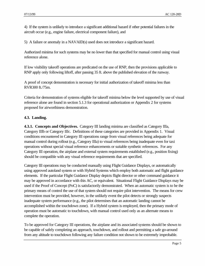
Landing and Rollout Flight Path - The following criteria specifies certain reference points and othercriteria necessary to effectively implement landing and rollout operations using a landing system wherethe required flight path is not inherent in the signal structure of the navigation aid (e.g., satellite systems).The location of points used to describe the landing and rollout flight path are shown in Figure 4.6-1.
Runway Datum Point (RDP) - The RDP is used in conjunction with the FPAP and a vector normal tothe WGS-84 ellipsoid at the RDP to define the geodesic plane of a final approach flight path to therunway for touchdown and rollout. It is a point at the designated lateral center of the landing runwaydefined by latitude, longitude, and ellipsoidal height. The RDP is typically a surveyed reference pointused to connect the approach flight path with the runway. The RDP may or may not necessarily becoincident with the designated runway threshold.
Flight Path Alignment Point (FPAP) - The FPAP is used in conjunction with the RDP and a vectornormal to the WGS-84 ellipsoid at the RDP to define the geodesic plane of a final approach and landingflight path. The FPAP may be the RDP for the reciprocal runway.
Flight Path Control Point (FPCP) - The FPCP is a calculated point located above the RDP in adirection normal to the WGS-84 ellipsoid. The FPCP is used to relate the vertical descent of the finalapproach flight path to the landing runway.
Datum Crossing Height [DCH] - The height (feet) of the FPCP above the RDP.
Glide Path Angle [GPA] - The glide path angle is an angle, defined at the FPCP, that establishes thedescent gradient for the final approach flight path of an approach procedure. It is measured in thegeodesic plane of the approach (defined by the RDP, FPAP, and WGS-84 ellipsoid’s center). Thevertical and horizontal references for the GPA are a vector normal to the WGS-84 ellipsoid at the RDPand a plane perpendicular to that vector at the FPCP, respectively.
Glidepath Intercept Reference Point [GIRP] - The GIRP is the point at which the extension of thefinal approach path intercepts the runway.
Figure 4.6-1

07/13/99 AC 120-28D
Page 21
Datum CrossingHeight (DCH)
Runway DatumPoint (RDP)
Glidepath InterceptReference Point (GIRP)
Flight PathControl Point(FPCP)
Flight Path Alignment Point(FPAP)
η
η = Glide Path Angle
The locations established for, and the values assigned to, the RDP, FPCP, DCH and GPA should beselected based upon the operational need to establish the GIRP. Operational considerations include:
1. Path of wheels over threshold,
2. Need for coincidence with other aids and systems - visual and non-visual, or markings
3. Runway characteristics (e.g., local slope in the touchdown zone, general runway upslope ordownslope, runway lateral crown),
4. Actual displaced thresholds or multiple runway thresholds,
5. Actual clearways or stopways
6. Construction temporary requirements
Takeoff Flight Path. The flight path for low visibility takeoff (while on the runway) should be definedby the RDP and FPAP.
4.7. Engine Inoperative Category III. The basic concept addressing expected flightcrew responseto non-normal situations, such as typically represented by an engine failure, is described in Section6.1.8.

AC 120-28D 07/13/99
Page 22
Engine Inoperative Category III is specifically addressed because for some modern aircraft and systems itis possible to retain and address Category III operating capability, as an alternate configuration. This is toaid operators and pilots in planning for and selecting more desirable and fully considered landing airportsthat may be closer in distance or time, have less adverse weather in terms of icy or short runways withadverse winds, are better equipped to handle a diversion or emergency, or provide a timely return to landat a takeoff airport or a closer takeoff alternate airport, in the unlikely event of engine failure or otherserious problem related to the engine failure.
With pre-planned engine inoperative Category III capability, airports and minima that otherwise may notbe considered acceptable for use could be selected by the pilot or operator without having tosubsequently justify its use based on emergency authority. This capability also has the advantage ofallowing for full pre-assessment of the aircraft capability, and engine inoperative aircraft configurations(e.g., flap settings, electrical system capability, hydraulic system capability), approach procedurecharacteristics, missed approach performance and other factors that may be difficult to assess in realtime if not previously assessed.
This capability also can permit an operator some additional flexibility in selecting alternate airports.
Accordingly Section 5.17 describes aircraft and airborne system criteria for credit for engine inoperativeCategory III capability. Sections 7.1.3 item 10, and 7.2.6 address crew qualification. Section 10.8addresses operational authorization and selection and use of alternates.
5. AIRBORNE SYSTEMS.
5.1. General.
5.1.1. Airborne Systems. Airworthiness criteria for airborne systems intended to meet criteria in thisAC are specified in paragraph 5.1.3 through 5.19 below for operational authorizations, or Appendix 2 fortakeoff, or Appendix 3 for landing and rollout for airworthiness demonstration of new or modified aircrafttypes or systems.
Aircraft shown to meet provisions of Appendix 2 or 3 respectively, are considered to meet provisionsof this section.
For aircraft approved using earlier versions of this AC, airworthiness criteria for airborne systemsintended for Category III operations are as specified in criteria referenced by the approved AFM.
Airborne equipment listed in this section needs to be operative for Category III, in accordance withprovisions of applicable standard Operations Specifications (OpSpecs) and Operations Specificationsfor that operator. Airframe manufacturers and individual operators may also include other optionalequipment as part of the Category III configuration, however, that equipment does not need to beoperative to conduct a Category III approach unless required by that operator's OpSpecs.

07/13/99 AC 120-28D
Page 23
Airborne systems making use of RNP capability for approach segments or missed approach segmentsshould be approved in accordance with or consistent with any one or more of the following criteria orprocesses:
1) FANS I or FANS A systems approved through a certification program acceptable to FAA, or
2) Through reference to an acceptable standard such as RTCA DO-236 for RNP, or
3) Through reference to RTCA DO-236 Appendix D for “fleet qualification” of existing aircraft, or
4) Through other FAA or FAA accepted equivalent criteria for intended for application orapproval of RNP (e.g., TERPS or PANS-OPS RNP provisions as adopted).
5.1.2. Non-Airborne Systems. Unless otherwise specified in the Appendices to this AC,NAVAID/landing system characteristics, including facility classification, should be considered asspecified in Section 4.3.10 above and AC 120-29 for ILS, MLS or GLS (e.g., U.S. use of ICAOAnnex 10 Criteria, FAA Order 6750.24 as amended, and the applicable NAVAID facility classificationfor Category III). NAVAID facility use is predicated on applicable ILS, MLS, or GLS Typeclassifications (e.g., ILS III/E/2, GLSII/D/2) or equivalent classification at non-U.S. facilities. SpecificNavigation Services are addressed in Section 5.12.
5.1.3. Takeoff Guidance Systems. When takeoff minima are predicated on use of a takeoffguidance system, the takeoff guidance system should be demonstrated to meet provisions of thisparagraph or provisions specified in Appendix 2 by an airworthiness demonstration. Takeoff guidancesystems which have been shown to meet Appendix 2 by airworthiness demonstration and have acorresponding AFM reference are typically considered to meet requirements of this paragraph.
A takeoff guidance systems shall be demonstrated to show that the airplane will not deviate significantlyfrom the runway centerline during takeoff while the system is being used within the limitations establishedfor it. Compliance may be demonstrated by flight test, or by a combination of flight test and simulation.Flight testing must demonstrate repeatable performance, and cover those factors affecting the behavior ofthis airplane (e.g., wind conditions, ILS characteristics, weight, center of gravity). Compliance with theperformance envelope should be demonstrated with pilots appropriately qualified to use the airbornesystem, and should not require extraordinary skill, training or proficiency.
Demonstrated winds should be 150% of the winds for which credit is sought, but not less than 15 knotsof headwind or crosswind.
In the event that the airplane is displaced from the runway centerline at any point during the takeoff orrejected takeoff, the system must provide sufficient guidance to enable the "pilot flying", or the pilot incommand who may assume control and become the "pilot flying", to control the airplane smoothly backto the runway centerline without significant overshoot or any sustained nuisance oscillation.
Figure 5.1.3-1 provides the performance envelope for evaluating takeoff command guidance systemsfor the following scenarios:

AC 120-28D 07/13/99
Page 24
a. Takeoff with all engines operating
b. Engine Failure at Vef - continued takeoff
c. Engine Failure just prior to V1 - rejected takeoff
d. Engine Failure at a critical speed prior to Vmcg rejected takeoff: (Vef < Vmcg)
Note: For that portion of the flight path following liftoff, the demonstrated lateral pathmay be adjusted for any effect of wind drift when showing compliance with theperformance envelope below.
Airplane Speed
Failure/Continued Take-off
Runway
Centerline
VFAILURE
+ 7m
0
+ 14m
Airplane Speed
All Engines Take-off
Runway
Centerline
V1VLOF
+ 7m
0
Airplane Speed
Failure/Rejected Take-off
Runway
Centerline
VFAILURE
+ 7m
0
+ 14m
h=35'
+ 14m
h=35'
STOP
FIGURE 5.1.3-1.
5.2. Airborne Systems for Category III Minima Not Less than RVR600. The followingequipment in addition to the instrument and navigation equipment required by 14 CFR part 91 for IFRflight is the minimum aircraft equipment considered necessary for Category III:

07/13/99 AC 120-28D
Page 25
1. A redundant flight control or guidance system, demonstrated in accordance with Appendix 3, or foraircraft types previously demonstrated acceptable earlier criteria described in previous versions of AC120-28 as amended, or acceptable international criteria, such as the JAR AWO.
Acceptable flight guidance or control systems include the following:
a. A Fail Operational or Fail Passive automatic landing system at least to touchdown, or
b. A Fail Operational or Fail Passive manual flight guidance system providing suitable head-upor head-down command guidance, and suitable monitoring capability at least to touchdown, or
c. A hybrid system, using automatic landing capability as the primary means of landing at leastto touchdown.
d. Other system which can provide an equivalent level of performance and safety.
NOTE: For system concepts not currently approved by FAA or system concepts notaddressed by Appendix 3, a proof of concept demonstration is required prior toeither airworthiness or operational consideration for approval.
2. An automatic throttle or automatic thrust control system which meets Appendix 3, orappropriate earlier criteria as specified in an FAA-approved AFM. However, for operations with a 50foot Decision Height, or other operations that have specifically been evaluated such as for engineinoperative landing capability, automatic throttles may not be required if it has been demonstrated thatoperations can safely be conducted, with an acceptable work load, without their use.
3. At least two independent navigation receivers/sensors providing lateral and vertical position ordisplacement information, typically with the first pilot's station receiving information from one and thesecond pilot's station receiving information from the other. The navigation receivers/sensors must meetthe criteria specified in Appendix 3 or equivalent, or must meet an earlier acceptable criteria as specifiedin an FAA AFM (e.g., 2 ILS localizer and glide slope receivers meeting performance requirements ofAC 120-28C; Appendix 1, paragraph 7a & b).
4. At least two approved radio altimeter systems which meet the performance requirementsoutlined in Appendix 3, or acceptable earlier criteria, as specified in an FAA AFM, typically with thefirst pilot's station receiving information from one and the second pilot's station receiving informationfrom the other.
5. Failure detection, annunciation, and warning capability, as described in Appendix 3, or asdetermined acceptable by earlier criteria, such as 120-28C; Appendix 1, paragraph 7c & 7g, andspecified in an FAA AFM.
6. Missed approach guidance provided by one or more of the following means:

AC 120-28D 07/13/99
Page 26
a. Attitude displays which include suitable pitch attitude markings, or a pre-establishedcomputed pitch command display.
b. An approved flight path angle display, or
c. An automatic or flight guidance go-around capability.
7. Suitable forward and side flight deck visibility for each pilot, as specified in 5.13.1.
8. Suitable windshield rain removal, ice protection, or defog capability as specified in 5.13.2.
5.3. Airborne Systems for Category III Minima Less Than RVR600.
5.3.1. Airborne Systems for Category III Minima Not Less than RVR400. The followingequipment in addition to the instrument and navigation equipment required by part 91 for IFR flight is theminimum aircraft equipment considered necessary for Category III operations to minima less thanRVR600 but not less than RVR400:
1. A redundant flight control or guidance system, demonstrated in accordance with Appendix 3, or foraircraft types previously demonstrated acceptable earlier criteria described in previous versions of AC120-28 as amended, or acceptable international criteria, such as the JAR AWO.
Acceptable flight guidance or control systems include the following:
a. A Fail Operational landing system with a Fail Operational or Fail Passive automatic rolloutsystem, or
b. A Fail Passive landing system (limited to touchdown zone RVR not less than RVR600) withFail Passive rollout provided automatically or by a flight guidance system providing suitable head-up orhead-down guidance, and suitable monitoring capability, or
c. A Fail Operational hybrid automatic landing and rollout system with compatible manual flightguidance system, using automatic landing capability as the primary means of landing.
d. Other system which can provide an equivalent level of performance and safety.
NOTE: For system concepts not currently approved by FAA or system conceptsnot addressed by Appendix 3, a proof of concept demonstration is required prior toeither airworthiness or operational consideration for approval.
2. An automatic throttle or automatic thrust control system which meets Appendix 3, orappropriate earlier criteria as specified in an FAA-approved AFM. However, for operations with a 50

07/13/99 AC 120-28D
Page 27
foot Decision Height, automatic throttles may not be required if it has been demonstrated that operationscan safely be conducted, with an acceptable work load, without their use.
3. At least two independent navigation receivers/sensors providing lateral and vertical position ordisplacement information, typically with the first pilot's station receiving information from one and thesecond pilot's station receiving information from the other. The navigation receivers/sensors must meetthe criteria specified in Appendix 3 or equivalent, or must meet an earlier acceptable criteria as specifiedin an FAA AFM (e.g., 2 ILS localizer and glide slope receivers meeting performance contained in AC120-28C; Appendix 1, paragraph 7a & b).
4. At least two approved radio altimeter systems which meet the performance criteria outlined inAppendix 3, or acceptable earlier criteria, as specified in an FAA AFM, typically with the first pilot'sstation receiving information from one and the second pilot's station receiving information from the other.
5. Failure detection, annunciation, and warning capability, as described in Appendix 3, or asdetermined acceptable by earlier criteria, such as 120-28C; Appendix 1, paragraph 7c & 7g, andspecified in an FAA AFM.
6. Missed approach guidance provided by one or more of the following means:
a. Attitude displays which include calibrated pitch attitude markings, or a pre-establishedcomputed pitch command display,
b. An approved flight path angle display, or
c. An automatic or flight guidance go-around capability.
7. Suitable forward and side flight deck visibility for each pilot, as specified in 5.13.1.
8. Suitable windshield rain removal, ice protection, or defog capability as specified in 5.13.2.
5.3.2. Airborne Systems for Category III Minima Not Less than RVR300 (75 m). Visibilityminima of RVR300 is applicable to those facilities reporting RVR in feet and which have appropriatereporting increments in feet. Visibility minima of 75m is applicable to those facilities reporting RVR inmeters and which have appropriate reporting increments in meters.
In addition to the aircraft equipment specified in 5.3.1 above, the following equipment is required forCategory III minima not less than RVR300 (75m):
1. A Fail Operational Automatic Flight Control System, or manual flight guidance system designedto meet fail operational system criteria, or a hybrid system in which both the fail-passive automaticsystem and the monitored manual flight guidance components provide approach and flare guidance totouchdown, and in combination provide full fail operational capability, and

AC 120-28D 07/13/99
Page 28
2. A fail operational rollout guidance or control system that can assure safe rollout to taxi speedconsisting of either:
a. A fail operational automatic rollout control system or fail operational manual flight guidancerollout system, or
b. A hybrid system consisting of at least a fail passive automatic rollout system and acompatible Fail Passive manual flight guidance rollout control system demonstrated in accordance withAppendix 3; (may be approved for operations not less than RVR300), or
3. Suitable flight instruments, annunciations, or crew procedures which can reliably detect and alertthe flightcrew to abnormal lateral or vertical flight path performance during an approach to touchdown,or abnormal lateral performance during rollout.
5.3.3. Airborne Systems for Category III Minima Less than RVR300 (75 m). In addition to theaircraft equipment specified in 5.3.2 above, the following equipment is required for Category III minimaless than RVR300 (75m):
1. A Fail Operational Automatic Flight Control System, or manual flight guidance system designed tomeet fail operational system criteria, or a hybrid system in which both the fail-passive automatic systemand the monitored manual flight guidance components provide approach and flare guidance to touchdown,and in combination provide full fail operational capability, and
2. A fail operational automatic, manual, or hybrid rollout control system.
5.4. Automatic Flight Control Systems and Automatic Landing Systems. Automatic FlightControl Systems or Autoland Systems considered acceptable for Category III, include:
1) Those systems meeting pertinent criteria of Appendix 3,
2) Those systems meeting acceptable earlier FAA criteria which have already been and currentlyare approved for use through operations specifications (whether or not specifically referenced in AFMprovisions), or
3) Those systems meeting other equivalent criteria (e.g., JAR AWO), found acceptable to theFAA.
5.5. Flight Director Systems. Characteristics of Flight Director Systems (head down or head up)used for aircraft authorized for Category III should be compatible with any characteristics of theautopilot or autoland system used. Flight control systems which provide both autopilot control and flightdirector information may or may not display flight director commands as appropriate for the systemdesign and operator requirements. Regardless of whether Flight Director commands are provided,

07/13/99 AC 120-28D
Page 29
situational information displays of navigation displacement must also be provided to both flightcrewmembers. To assure that unacceptable deviations and failures can be detected, the displays must beappropriately scaled and readily understandable in the modes or configurations applicable.
"Flight director systems" may be considered as "fail passive" if after a failure, the flight path of the aircraftdoes not experience a significant immediate deviation due to the pilot following the failed guidancebefore the pilot detects the failure and discontinues using the guidance.
5.6. Head-up Display Systems. Head-up Display systems used as the basis for a suitable CategoryIII authorization must provide guidance for one or both pilots as appropriate for the system design. Ifinformation is provided to only the flying pilot, then appropriate monitoring capability must beestablished for the non flying pilot. Monitoring tasks must be identified, and the non flying pilot must beable to assume control of the aircraft in the event of system failure or incapacitation of the pilot using theHead-up Display (e.g., for a safe go-around or completion of rollout). Head-up Display Systemsacceptable for Category III must meet provisions of Appendix 3, or acceptable earlier criteria specifiedby the FAA and referenced in an AFM.
"Head-up Display systems" may be considered as "fail passive" if:
1. After a failure, the pilot using the system or pilot monitoring the system is made aware of thefailure in a timely manner, and
2. The flight path of the aircraft does not experience a significant immediate deviation from theintended path due to the pilot following the failed guidance before the pilot flying or pilot monitoringdetects the failure, and the pilot flying discontinues using the guidance.
5.7. Enhanced/Synthetic Vision Systems. Enhanced/Synthetic Vision Systems based on millimeterwave radar or other such sensors may be used to assure the integrity of other flight guidance or controlsystems in use during Category III operations. They must be demonstrated to be acceptable to FAA ina proof of concept evaluation and they must otherwise be in accordance with Appendix 3. Use ofEnhanced/Synthetic Vision Systems for purposes other than establishing the accuracy or integrity offlight guidance system performance must be demonstrated to be acceptable through proof of concepttesting prior to identification of specific airworthiness and operation criteria.
5.8. Hybrid Systems. Hybrid systems (e.g., a fail passive autoland system used in combination with amonitored HUD flight guidance system) may be acceptable for Category III if each element of thesystem alone is shown to meet its respective suitability for Category III, and if taken together, thecomponents provide the equivalent performance and safety to a non-hybrid system as specified for theminima sought (e.g., fail operational Category IIIb).
Hybrid systems with automatic landing capability should be based on the concept of use of theautomatic landing system as the primary means of control, with the manual flight guidance system servingas a backup mode or reversionary mode.

AC 120-28D 07/13/99
Page 30
Manual rollout flight guidance capability must be provided for hybrid systems which do not haveautomatic rollout capability. Such manual rollout capability must have been shown to have performanceand reliability at least equivalent to that of a fail passive automatic rollout system.
Any transition between hybrid system elements (e.g., control transition from autoland use to manualcontrol HUD use, or for response to failures) must be acceptable for use by properly qualifiedflightcrews (e.g., qualified in accordance with part 121, SFAR 58, or equivalent JAA criteria, asapplicable, and standard industry practices). Transitions should not require extraordinary skill, training,or proficiency.
For any system which requires a pilot to initiate manual control near or shortly after touchdown, thetransition from automatic control prior to touchdown to manual control using the remaining element ofthe hybrid system (e.g., HUD) after touchdown must be shown to be safe and reliable.
For hybrid systems, operational procedures following failure of the automatic system or flight guidancesystem prior to touchdown may require that the pilot initiate a go-around, even though the aircraft usinga hybrid system must have been demonstrated as being capable of safely completing a landing androllout following a failure of one of the hybrid system elements below alert height.
A hybrid system may be approved for Category III if it is shown to meet the criteria specified in Appendix3 when approved through an airworthiness demonstration process. Alternately, a hybrid system may beacceptable for Category III if it is determined to meet applicable airworthiness criteria for each element ofthe system separately (e.g., separately meets Category III criteria for autoland and HUD), and in addition,a successful operational suitability demonstration is completed using the individual system elementstogether as a hybrid system. If acceptability is determined through an operational demonstration process,the individual elements of the hybrid system must be shown to be compatible for both normal and non-normal operations, and the combined system must be shown to have the necessary performance, integrity,and availability appropriate for the operations intended.
An operator may receive approval to use an automatic landing system and a manual flight guidance systemas a Hybrid System provided, (a) each system individually meets appropriate airworthiness assessments,and (b), that operator conducts a successful operational demonstration showing the hybrid system'scapability to meet applicable provisions of this section.
For hybrid systems used for Category III an Alert Height of 50' or higher should be used unlessotherwise approved by the FAA AFS-400.
5.9. Instruments and Displays. Flight instrument and display presentations related to Category III,including attitude indicators, EADI’s, primary flight displays, EHSI’s, HIS’s, or other such navigationdisplays must provide pertinent, reliable and readily understandable information for both normal and non-normal conditions related to Category III landing and missed approach.

07/13/99 AC 120-28D
Page 31
Alert Height and/or Decision Height indications must be readily understandable, appropriatelyhighlighted, and not be compromised by effects such as typical underlying terrain on the final approachpath, and other annunciations or automatic audio call-outs. In addition, instruments and displays shouldprovide appropriate indications considering terrain characteristics identified in Appendix 3 Section6.3.4. Controls for altitude or height alerts used for minima determination or alert heights should usestandard indications such as RH for radio height (or RA for radio altitude) and BARO for barometricaltitude, rather than operational designations such as DH or MDA. Use of the designation RH or RAfor height referenced values, or BARO for barometric altitude referenced values for controls or displaysdo not preclude related use of display symbology color changes or use of flashing alphanumericsymbology as the aircraft descends below a specifically referenced height or altitude value.
Situation information displays of navigation displacement must be available to both flightcrew members,and must be appropriately scaled and readily understandable in presentations or mode of display used.Instrument and panel layouts must follow accepted principles of flight deck design.
5.10. Annunciations. Annunciations must be clear, unambiguous, and appropriately related to theflight control mode in use. The mode annunciation labels should not be identified by landing minimaclassification. For example, LAND 2, LAND 3, Single Land, Dual Land, etc., are acceptable modeannunciation labels, whereas, Category II, Category III, etc., should not be used. Aircraft previouslydemonstrated for Category III which do not meet this criteria may require additional operationalconstraints to assure the correct use of minima suited to the aircraft configuration. In addition, modeannunciation labels must be consistent with other annunciations in the cockpit, and with the airplanedocumentation.
5.11. Automatic Aural Alerts. Automatic Aural Alerts (e.g., automatic call-outs, voice callouts) ofradio altitude, or call-outs approaching landing minimums, or call-outs denoting landing minimums must beconsistent with the design philosophy of the aircraft in question. However, any automatic call-outs usedshould not be of a volume or frequency that interferes with necessary flightcrew communications or normalcrew coordination procedures. Recommended automatic call-outs include a suitable alert or tone asfollows:
1. At 500 ft. (radio altitude), approaching minimums and at minimums, and
2. Altitude call-outs during flare, such as at "50" ft., "30" ft. and "10" ft., or altitudes appropriate toaircraft flare characteristics. Low altitude radio altitude call-outs, if used, should appropriately addressthe situation of higher than normal sink rate during flare, or an extended flare which may be progressingbeyond the touchdown zone.
5.12. Navigation Sensors. Various navigation sensors may be acceptable to support Category IIIoperations as specified in Section 4.3.10. ILS localizer and glideslope signals are the primary meanscurrently used for the determination of deviation from the desired path for Category III operations.Criteria for acceptable ILS and MLS localizer and glide-slope receivers are included in Appendix 3 or inearlier acceptable criteria used by FAA for previous demonstrations of systems for Category III. Other

AC 120-28D 07/13/99
Page 32
navigation sensors, such as GNSS, or DGNSS, may be used individually or in combination to satisfy thenecessary accuracy, integrity and availability for Category III if proof of concept demonstrations aresuccessfully completed and operational experience at Category I and Category II minimums is acceptable.Navigation sensors other than ILS must meet equivalent ILS performance or appropriate RTCA orEUROCAE criteria, unless otherwise authorized.
Appropriate marker beacon information, or equivalent, must be displayed to each pilot for the outer,middle and inner markers. Appropriate substitutes for marker beacons may be authorized by the FAAfor Category III based upon the use of suitable GNSS/DGNSS capabilities, or DME.
5.13. Supporting Systems and Capabilities.
5.13.1. Flight Deck Visibility. Suitable forward and side flight deck visibility for each pilot should beprovided as follows:
a. The aircraft should have a suitable visual reference cockpit cutoff angle over the nose for theintended operations, at the intended approach speeds, and for the intended aircraft configurations, asapplicable (e.g., flap settings),
b. The aircraft's flight deck forward and side windows should provide suitable visibility for taxi andground operations in low visibility, and
c. Placement of any devices or structure in the pilots visual field which could significantly affect thepilot's view for low visibility operations must be acceptable (e.g., HUD drive electronics, sunvisorfunction or mountings).
5.13.2. Rain and Ice Removal. Suitable windshield rain removal, ice protection, or defog capabilityshould be provided as specified below:
a. Installation of rain removal capability is required (e.g., windshield wipers, windshield bleed air).
b. Installation and use of windshield hydrophobic coatings, or use of equivalent rain repellentsystems which meet pertinent environmental standards are recommended.
c. Installation of windshield anti-ice or de-ice capability is required for aircraft intended to operatein known icing conditions during approach and landing.
d. Installation of at least forward windshield defog capability is recommended for aircraft subject toobscuration of the pilot's view during humid conditions.

07/13/99 AC 120-28D
Page 33
Aircraft subject to obscuration of the windshield due to rain, ice, or fogging of the pilot's view which donot have protection, or which do not have adequate protection may require operational limitations onthe conditions in which low visibility operations are conducted.
5.13.3. Miscellaneous Systems. Other supporting systems should meet appropriate criteriacompatible with Category III Operational Objectives. Applicable criteria may include criteria asspecified in Appendix 3, criteria as specified in basic airworthiness requirements applicable to U.S.certificated aircraft, or equivalent, or operational criteria for IFR flight. Regarding supporting systems,“In-service aircraft” or “new production” aircraft may meet or continue to meet criteria previously foundacceptable for Category III operation for supporting systems for those aircraft. Supporting systems forCategory III are considered to include, as applicable: Instruments, radar altimeters, air data computers,inertial reference units, attitude and heading gyros, instrument switching, flight deck night lighting, landinglights and taxi lights, position lights, turnoff lights, recognition lights, GPWS or EGPWS, flight datarecorders or other low visibility related aircraft systems pertinent to a particular type.
Any GPWS or EGPWS systems interfaces (e.g., glide slope deviation warning) should be compatiblewith and should not interfere with the Category III Operations to be conducted (e.g., for engineinoperative Category III Configurations). For multimode capable systems for Category III (e.g., MMR),interfaces with GPWS or EGPWS for each MMR mode (e.g., ILS, MLS or GLS) should be consistent.
For Flight Data Recorders (FDR’s) or Quick Access Recorders (QAR’s), it is recommended thatoperators consider appropriate flight data recorder requirements for incident or event analysis whenaddressing provisions for Category III. It is recommended that any data recorders installed providesufficient capability for recording of parameters applicable to flight guidance system performance for usewith Category III operations. Typical parameters of interest and appropriate sample rates are thosefound in Appendix 8 applicable to Irregular Terrain Assessment.
5.14. Go-Around Capability. Regardless of the flight guidance system used an appropriate go-around mode/capability should be provided. A go-around mode/capability must be able to be selectedat any time during the approach to touchdown. The go-around mode/capability should provideinformation for a safe discontinuance of the approach at any point to touchdown, if activated prior totouchdown. If activated at a low altitude where the aircraft inadvertently touches the ground, the go-around mode should provide adequate information to accomplish a safe go around and not exhibitunsafe characteristics as a result of an inadvertent touchdown. Inadvertent selection of go-around aftertouchdown should have no adverse effect on the ability of the aircraft to safely rollout and stop.
5.15. Excessive Deviation Alerting. An acceptable method should be provided to detect excessivedeviation of the aircraft laterally and vertically during approach, and laterally during rollout, as applicable.The method used should not require excessive workload or undue attention. This provision does notrequire a specified deviation warning method or annunciation, but may be addressed by parametersdisplayed on the ADI, EADI, or PFD. When a dedicated deviation warning is provided, its use must notcause excessive nuisance alerts.

AC 120-28D 07/13/99
Page 34
5.16. Rollout Deceleration Systems or Procedures for Category III.
5.16.1. Stopping Means. A means to determine that an aircraft can be reliably stopped within theavailable length of the runway is necessary to conduct Category III operations. At least one of thefollowing means to assess stopping performance should be used:
1. An automatic braking system which includes information for the flightcrew about appropriateauto brake settings to be used for landing or which provides landing distance information suitable for useby the flightcrew to determine which auto brake setting may or may not be appropriate.
2. A ground speed indicating system based on inertial information or other equivalent source suchas GNSS, together with acceptable procedures for its use.
3. A deceleration display or other indication which can advise the pilot of the adequacy of aircraftdeceleration to stop within the available runway length.
4. A runway remaining indicator display reliably showing the length of remaining runway aftertouchdown.
5. A procedural means to assure a safe stop acceptable to FAA. However, a procedural means toensure a safe stop is not appropriate for minima less than RVR300 (75 m).
5.16.2. Antiskid Systems. Unless otherwise determined to be acceptable to the FAA, aircraftauthorized for Category III should have an operable anti-skid system installed and operative per theapplicable FAA MMEL and MEL.
The authorization for aircraft to operate using Category III minima without anti-skid is determined by thePOI for each aircraft type, considering the following factors:
1. Extra field length margin of runways to be authorized, compared with field lengths necessary forthe aircraft type, and
2. The braking system characteristics of the aircraft regarding susceptibility to tire failure duringheavy braking, and susceptibility to tire failure during operations with reduced or patchy runway surfacefriction.
5.17. Engine Inoperative Category III Capability. The following criteria are applicable to aircraftsystems intended to qualify for "engine inoperative Category III" authorizations. Aircraft demonstratedto meet "engine inoperative" provisions of Appendix 3 that have an appropriate reference to engineinoperative Category III capability in the FAA approved AFM are typically considered to meet theprovisions listed below.

07/13/99 AC 120-28D
Page 35
The AFM or equivalent reference must suitably describe demonstrated approach and missed approachperformance for the engine inoperative configuration, and the aircraft must meet pertinent criteriaotherwise required for all-engine Category III or equivalent criteria. This performance data should alsobe available in the automated flight planning, performance and weight and balance systems normallyused by the air carrier so as to be readily available to the pilot and, if applicable, the aircraft dispatcher.
Exceptions to all-engine Category III, or equivalent criteria, may be authorized for engine inoperativeCategory III as follows:
a. The effects of a second engine failure when conducting Category III operations with anengine inoperative need not be considered, except for a demonstration that the airplane remaincontrollable when the second engine fails,
b. Crew intervention to re-trim the aircraft to address thrust asymmetry following engine lossmay be permitted,
c. Alternate electrical and hydraulic system redundancy provisions may be acceptable, as suitedto the type design (e.g., bus isolation and electrical generator remaining capability must be suitable forthe engine out configuration),
d. Requirements to show acceptable landing performance may be limited to demonstration ofacceptable performance during engine out flight demonstrations (e.g., a safe landing on the runway), and
e. Landing system "status" should accurately reflect the aircraft configuration and capability.
2. Suitable information must be available to the flightcrew at any time in flight, and particularly at thetime of a "continuation to destination" or "diversion to alternate” decision. This is to determine that theaircraft can have an appropriate Category III approach capability when the approach is initiated (e.g.,Non-normal checklist specification of expected configuration during approach, autoland statusannunciation of expected capability).
3. Performance should be demonstrated in appropriate weather conditions considering winds andany other relevant factors.
5.18. Airborne System Assessment for Irregular Pre-Threshold Terrain. Not withstanding thatairworthiness demonstrations may consider irregular terrain in the pre-threshold area, special operationalevaluations are nonetheless required for certain airports having difficult pre-threshold terrain conditions (seeSection 6.2.5). Criteria for the operational evaluation of irregular pre-threshold terrain airports is containedin Appendix 8. This criteria may be used both for operational authorizations and in conjunction withairworthiness demonstrations for type certification (TC) or supplemental type certification (STC).

AC 120-28D 07/13/99
Page 36
5.19. Airworthiness Demonstrations of Airborne System Capability for Category III.Airworthiness demonstrations of airborne systems not previously approved for Category III should bein accordance with the provisions of Appendices 2 through 6. Aircraft which have previouslycompleted airworthiness demonstrations in accordance with earlier criteria may continue to referencethe demonstrations against earlier criteria in their AFM and may elect to continue to use earlier criteriafor continued production or demonstration of new production derivative aircraft. The criteria of this ACmust be used when seeking credit not provided by the earlier criteria, for new aircraft types, or forsignificantly modified systems proposed to FAA for derivative aircraft after the date of the issuance ofthis revised AC. Category III aircraft systems may be evaluated in accordance with the applicablecriteria contained in the Appendices of this AC during airworthiness demonstrations, or they may beevaluated in conjunction with an FAA approved program with an operator, for aircraft that are "inservice" using the equivalent criteria and evaluation methods, to those specified in the Appendices to thisAC. Operational demonstrations will not be conducted based on criteria prior to this AC.
6. PROCEDURES.
6.1. Operational Procedures. Appropriate operational procedures based on the approved operatorprogram should be addressed. Operational procedures should consider the pilot qualification andtraining program, airplane flight manual, crew coordination, monitoring, appropriate takeoff and landingminima including specification of either a Decision Height or an Alert Height (as applicable) for landing,crew call-outs, and assurance of appropriate aircraft configurations. Suitable operational proceduresmust be used by the operator and be used by flightcrews prior to conducting low visibility takeoff orCategory III landing operations.
6.1.1. Application of AFM Provisions. The operator's procedures for low visibility takeoff orCategory III landing should be consistent with any AFM provisions specified in the normal or non-normal procedures sections (e.g., Section 3 of the AFM) during airworthiness demonstrations.Adjustments of procedures consistent with operator requirements are permitted when approved by thePOI. Operators should assure that no adjustments to procedures are made which invalidate theapplicability of the original airworthiness demonstration.
Where navigation performance for a specific RNP can only be achieved by specific system modes (e.g.,coupled flight director or autopilot), the specific modes and associated RNP levels should be appliedconsistent with the AFM.
Where operations are based on RNP, suitable flight manual provisions for RNP capability and useshould be provided. If not available in the AFM or Flight Crew Operating Manual (FCOM), RNPoperations may be approved on a case by case basis, consistent with “fleet qualification” for RNPcriteria such as found in RTCA DO-236 Appendix D, or equivalent FAA criteria.
6.1.2. Crew Coordination. Appropriate procedures for crew coordination should be established sothat each flightcrew member can carry out their assigned responsibilities. Briefings prior to the

07/13/99 AC 120-28D
Page 37
applicable takeoff or approach should be specified to assure appropriate and necessary crewcommunications. Responsibilities and assignment of tasks should be clearly understood bycrewmembers.
6.1.3. Monitoring. Operators should establish appropriate monitoring procedures for each lowvisibility takeoff, approach, landing, and missed approach. Procedures should assure that adequatecrew attention can be devoted to control of aircraft flight path, displacements from intended path, modeannunciations, failure annunciations and warnings, and adherence to minima associated with DH andAH. Where a "monitored approach" is used, (e.g., where the First Officer is responsible for control ofthe aircraft flight path by monitoring of the automatic flight system) appropriate procedures should beestablished for transfer of control to the captain who will be making the decision for continuation of thelanding at or prior to Decision Height or Alert Height. Monitoring procedures should not require atransfer of responsibility or transfer of control at a time that could interfere with safe landing of theaircraft. Procedures for calling out failure conditions should be pre-established, and responsibility foralerting other crewmembers to a failure condition should be clearly identified.
6.1.4. Use of the Decision Height or Alert Height. Decision heights are normally used for FailPassive Category III operations and Alert Heights are used for Fail Operational Category III operations.Certain exceptions are noted elsewhere in this AC (e.g., use of a Decision Height (DH) due to specificfail operational aircraft characteristic at a runway with irregular pre-threshold terrain). When DecisionHeights are specified, procedures for setting various reference bugs in the cockpit should be clearlyidentified, responsibilities for Decision Height call-outs should be clearly defined, and visual referencerequirements necessary at Decision Height should be clearly specified so that flightcrews are aware of thenecessary visual references that must be established by, and maintained after passing Decision Height.
When Alert Heights are specified, the operator may elect to use an Alert Height at or below 200 ft. HATas suitable for procedure or procedures identified for use by that operator.
Procedures should be specified for call-out of the Alert Height and if applicable for conversion of theAlert Height to a Decision Height in the event that the aircraft reverts from Fail Operational to FailPassive flight control.
The operator should assure that at each runway intended for Category III operations, the radar altimetersystems used to define Alert Height or Decision Height provides consistent, reliable, and appropriatereadings for determination of Decision Height or Alert Height in the event of irregular terrain underlyingthe approach path, or an alternate method should be used. Alert Height or DH may be based on othermeans (e.g., inner marker) only when specifically approved by FAA. Any adjustments to approachminima or procedures made on final approach should be completed at a safe altitude (e.g., above 500ft. HAT).

AC 120-28D 07/13/99
Page 38
6.1.5. Call-outs. Altitude/Height call-outs should be used for Category III. Callouts may beaccomplished by the flightcrew or may be automatic (e.g., using synthetic voice call-outs or a tonesystem). Typical call-outs acceptable for Category III include a combination of the following:
• "1000 ft." above the touchdown zone,
• "500 ft." above the touchdown zone,
• "approaching minimums,"
• "minimums,"
• altitudes during flare, (e.g., 50, 30, 10) or AFGS mode transitions (e.g., flare, rollout), and
• as appropriate, auto spoiler, reverse thrust deployment and autobrake disconnect.
Calls made by the flightcrew should not conflict with the automatic systems or auto call-outs of theaircraft, and conversely the configuration selected for the aircraft should not conflict with expected call-outs to be made by the flightcrew. Compatibility between the automatic call-outs and the crew call-outsmust be assured. The number of call-outs made, either automatically, by crew, or in combination,should not be so frequent as to interfere with necessary crew communication for abnormal events.
Also, call-outs should be specified to address any non-normal configurations, mode switches, failedmodes, or other failures that could affect safe flight, continuation of the landing, or the accomplish-mentof a safe missed approach. Any use of crew initiated call-outs at altitudes below 100 ft. should assurethat the callouts do not require undue concentration of the non-flying pilot on reading of the radaraltimeter rather than monitoring the overall configuration of the aircraft, mode switching, andannunciations that might be related to a successful Category III landing. Automatic altitude call-outs ortones are recommended for altitude awareness, at least at and after passing Decision Height or AlertHeight.
Operators may make provision for use of crew verbal callouts as a backup, or in lieu of automaticcallouts in certain circumstances. It is recommended that operators have a policy addressingprocedures to be used when an automatic callout system fails or is inoperative regarding making someor all key callouts manually. Examples of when use of verbal crew callouts may be appropriate insteadof or to augment automatic callouts include:
1) When an automatic callout system has failed,
2) When automatic callouts are inoperative through an MEL provision, or
3) When a particular automatic callout is not issued or is masked by another cockpit advisory or crewconversation, or is not heard for some other reason.

07/13/99 AC 120-28D
Page 39
6.1.6. Aircraft Configurations. Operational procedures should accommodate any authorized aircraftconfigurations that might be required for low visibility takeoff or Category III approaches or missedapproaches. Examples of configurations that operational procedures may need to accommodateinclude:
1. Alternate flap settings approved for Category III,
2. Use of alternate AFGS modes or configurations (e.g., Single Land, LAND2),
3. Inoperative equipment provisions related to the minimum equipment list, such as a non-availability ofcertain electrical system components, inoperative radar altimeter, air data computers, hydraulic systems orinstrument switching system components, and
4. Availability and use of alternate electrical power sources (e.g., APU) if required as a standby source.
Procedures required to accommodate various aircraft configurations should be readily available to theflightcrew and the aircraft dispatcher to preclude the inadvertent use of an incorrect procedure orconfiguration. Acceptable configurations for that operator and aircraft type should be clearly identifiedso that the pilots can easily determine whether the aircraft is or is not in a configuration to initiate a lowvisibility takeoff or Category III approach. Configuration provisions must be consistent with, but are notlimited to, those provided in the operations specifications for that operator.
6.1.7. Compatibility with Category I and Category II Procedures. The operator should assurethat to the greatest extent possible, procedures for Category III are consistent with the procedures forthat operator for Category II and Category I to minimize confusion about which procedure should beused or to preclude procedural errors due to pilots reverting to familiar procedures accomplished morefrequently such as for Category I. The operator should to the extent practical, minimize the number ofprocedures that the crew needs to be familiar with for low visibility operations so that, regardless of thelanding category necessary for an approach, the correct procedures can be used consistently andreliably.
6.1.8. Flightcrew Response to Non-Normal Events. Takeoff and landing weather minimums areintended for normal operations. When non-normal events occur, flightcrews and aircraft dispatchers areexpected to take the safest course of action to assure safe completion of the flight. Using emergencyauthority, pilots can deviate from rules or polices, to the extent necessary, to minimize the risk ofcontinued flight to a safe landing. In some instances, guidelines are established for particular failuresituations, such as failure of required aircraft systems prior to reaching Alert Height.
When procedures or configurations have not been specified, pilots and aircraft dispatchers are expectedto use good judgment in making the determination of appropriate configurations or situations to conductsafe Category III operations. The decision to continue an approach or to discontinue an approach must

AC 120-28D 07/13/99
Page 40
be made considering all relevant factors of the status of the aircraft, fuel on board, seriousness of theemergency, distance away of other available airports, and the likelihood of changing weather conditions,among other factors. It is not the intent of this AC to attempt to define guidelines for circumstances suchas in-flight fire, minimum fuel reserves, or other situations requiring complex judgments of skilledcrewmembers.
However, in the case of certain well-defined situations that can be addressed before departure, such ascontingency planning in the event of an engine failure, guidelines are provided to assist pilots in makingsafe and consistent judgments about available alternative courses of action. Specific guidelines forinitiation for a Category III approach with an inoperative engine are provided in section 5.17.Guidelines for other configuration situations may be provided by the normal or non-normal proceduresection of the aircraft flight manual or by the operator. Pilots and aircraft dispatchers are expected to befamiliar with these guidelines and apply them to the extent practical but may deviate as necessary fromthose guidelines, to the extent that they consider necessary to assure safe flight and landing. If doubtexists as to the advisability of continuation of an approach or diversion, it is the flightcrews responsibilityto exercise their emergency authority to the extent necessary to assure a safe flight.
6.2. Category III Instrument Approach Procedures and Low Visibility Takeoff.
6.2.1. Takeoff Guidance System Procedures. When takeoff minima are predicated on use of atakeoff guidance system meeting the criteria of Section 5.1.3 or Appendix 2, procedures for use of thetakeoff guidance system should be identified consistent with the approved AFM, or applicable operationalauthorization. Procedures should address at least the following items or factors:
• Setup, test, and initialization of the guidance system and NAVAID’s, as applicable
• Roles and responsibilities of the PF and PNF
• Suitable alignment with and tracking of the runway centerline
• Suitable transfer of control between pilots for failures or incapacitation, as applicable
• Suitable response to failures (e.g., engine failure before and after V1, electrical failure, guidancesystem alerts, warnings, and failures as applicable)
6.2.2. Acceptable Procedures for Category III Approach. Instrument Approach Procedures forCategory III may be conducted in accordance with:
1. published 14 CFR part 97 procedures, or
2. approved operations specifications for special procedures, or

07/13/99 AC 120-28D
Page 41
3. published foreign or military procedures approved by the FAA, or
4. foreign or military procedures accepted by FAA for specific foreign airports and runways.
6.2.3. Standard Obstacle clearance for approach and missed approach. Advisory Circular 120-29 as amended provides the standard Category II and III approach and missed approach criteria nototherwise specified in FAA Order 8260.3 (TERP’s). The criteria in AC 120-29 should be appliedexcept where acceptable TERP’s criteria is provided for Category II and III operations using ILS,MLS, GLS or RNP facilities and equipment. Standard obstacle clearance criteria are typicallyincorporated with published part 97 procedures. Standard criteria used by several foreign authoritiesbased on ICAO PANS OPS may be used where found to be acceptable to the FAA (e.g., JAAapproved procedures). Category II and III procedures developed using criteria other than TERPS orPANS OPS are normally issued through operations specifications as special procedures. (Seeparagraph 6.2.4.) 6.2.4. Special Obstacle Criteria. In certain instances standard obstacle criteria as specified byTERPS may not be appropriate for particular Category III procedures. In such instances alternatecriteria acceptable to the FAA may be used as specified in OpSpecs (e.g., RNP criteria). 6.2.5. Irregular Terrain Airports. Irregular terrain airports identified by a part 97 procedure, or byFAA order 8400.8, as amended, must be evaluated in accordance with FAA approved proceduresprior to incorporation in operations specifications for use by air carriers operating to Category IIIminima. Irregular terrain airport special evaluations should consider each particular aircraft type, the particularflight control system, and may include consideration of particular system elements such as the type ofradar altimeters installed or other equipment. Procedures for evaluation of these airports are provided in Appendix 8.
6.2.6. Airport Surface Depiction for Category III Operations. A suitable airport surfacedepiction (e.g., airport diagrams) should be available to flightcrews to assure appropriate identificationof visual landmarks or lighting to safely accomplish taxing in Category III conditions from the gate to therunway and from the runway to the gate. The Airport depiction should use an appropriate scale withsuitable detailed information on gate locations, parking locations, holding locations, critical areas,obstacle free zones, taxi way identifications, runway identifications, and any applicable taxi waymarkings for designated holding spots or holding areas. Standard depictions provided by commercialcharting services are typically acceptable if they provide sufficient detail to identify suitable routes of taxito and from the runway and gate positions for departure or arrival.
6.2.7. Continuing Category III Approaches in Deteriorating Weather Conditions. Thefollowing procedures are considered acceptable in the event that weather conditions are reported todrop below the applicable Category III minima after an aircraft has passed the final approach point orfinal approach fix, as applicable. (Reference section 121.651.)

AC 120-28D 07/13/99
Page 42
• Operations based on a DA(H) may continue to the DA(H) and then land, if the specified visualreference is subsequently established by the pilot no later than the DA(H).
• Operations based on an Alert Height (AH) may continue to the AH and then land, if weather isreported to be at or above minima before passing the AH, or if suitable visual reference hasbeen established by the pilot.
• Operations based on an AH may continue to land regardless of reported weather conditions ifequipped with a fail operational rollout system which did not indicate a malfunction prior topassing alert height, and the pilot considers continuation a safe course of action.
Operators requesting amended operations specifications reflecting the procedures described above mayhave their current operations specifications amended by making application in accordance withparagraph 10.16. New Category III operators should have operations specifications issued reflectingthese provisions in accordance with revised standard operations specifications (see samples provided inAppendix 7).
When wind constraints apply to Category III procedures (e.g., an Operation-Specification 15 knotcrosswind component limit) the limit is considered to apply to the point of touchdown. If a report of acrosswind component value greater than the limit is received while on approach, an aircraft maycontinue an approach, but a subsequent wind report indicating winds are within limits or a pilotdetermination that actual winds are within limits must be made prior to touchdown. Acceptablemethods for such a determination may include ATS reports, reports of other aircraft with reliable meansof wind determination (e.g., IRS), pilot use of on board IRS or FMS wind readout capability, data linkof recent winds, or pilot confirmation of an acceptable visual indication of winds on the surface by awind sock, wind indicator or equivalent wind indicating device.
When an Airplane Flight Manual or other manufacturer’s reference (e.g., FCOM) references“Maximum wind component speeds when landing weather minima are predicated on autolandoperations”, or an equivalent statement, an operator or flightcrew may consider those wind values toapply to “steady state” wind components. Any gust values which exceed the steady state wind limitneed not be addressed if the flightcrew determines the gust exceedance can be considered insignificantin magnitude, variable in direction, occasional, or otherwise not applicable (e.g., obviously outdated gustreport, winds and gusts reported at a location considered far from the runway or touchdown zone andnot applicable, or gusts considered not pertinent during the period of touchdown or rollout).
6.2.8. Low Visibility Taxi Procedures. Low visibility taxi procedures should be adopted for eachairport having such procedures. The procedures should be available to pilots in chart form, ifapplicable, and used. In addition to published Surface Movement Guidance and Control System(SMSGS) airport diagrams and information, the operator should provide:

07/13/99 AC 120-28D
Page 43
• Any necessary specific gate identification information to find gates, ramp areas, or lead invehicles,
• Any necessary information about identification of critical area protection zones or areas,
• Any necessary emergency response information for takeoff, landing, or other emergencies that
are different for low visibility operations (e.g., markings or other ways to easily find and identifyexplosive holding areas in low visibility),
• Information on any known characteristics of the airport where aircraft ground vehicle traffic
conflicts, taxi speed, or aircraft wing tip clearance pose unusual difficulty,
• Any other information necessary to facilitate safe operations in very low visibility (e.g., visualreferences that may be used for operations when standard markings may not be visible due toconstruction, snow cover).
Provision should be made for both day and night operation, unless operations are only conducted duringeither night or daylight hours.
Low visibility taxi and ground operations and related training and qualification are addressed in Sections7.1.1 item 3 and 7.1.3 item 5 for ground training, Section 7.2 for flight training, and Section 8.5 forSMGCS Plans.
6.2.9. Navigation Reference Datum Compatibility (e.g.,WGS-84/Other Datum).
Outside the U.S., it is important for operators using FMS, GPS and RNAV to be aware of, and wherenecessary, take precautions to address potential differences in the Navigation Data Base (NDB)"reference datum" used by their aircraft's navigation system, and the datum used en route and atdestination or alternate airports. Some States specify aeronautical data (e.g., NAVAID locations,runway locations, waypoint locations), including data for instrument procedures, using a reference datumother than the standard WGS-84 datum, or equivalent.
Addressing this difference can be important to preclude significant navigation errors. If notappropriately addressed, aircraft actual position may significantly differ from indicated position whenflying in these areas. Aircraft may experience navigation difficulty including:
• Incorrect FMS position updating, • Incorrect navigation to a waypoint, NAVAID, runway, or other geographic location, • Violation of airspace or obstacle clearance during approach or missed approach, • Displacement from the desired flight path, or runway misalignment following completion of an
instrument approach, or

AC 120-28D 07/13/99
Page 44
• Significant map shift, if FMS position is based on updates from NAVAID(s) referenced to a localdatum inconsistent with that of the aircraft's navigation data base.
Also, this issue can be important when flying with FMS using a WGS-84 referenced navigation database with "GPS updating capability" installed, but not operative (e.g., as for an FMS MEL dispatch,with GPS inoperative, GPS updating inoperative; or GPS updating inhibited).
For Category III procedures, the issue of use of an appropriate Navigation "Reference Datum"principally applies to flying RNAV initial or intermediate approach segments, or missed approachsegments. Final approach segments of ILS or MLS procedures typically are not adversely affected bya difference in reference datum because of direct use of the localizer course. GLS or RNP procedures,while depending on specification of an appropriate reference datum for final approach, are otherwiseprotected from this datum difference through other criteria which assures consistent datum use forprocedure development.
Information about the navigation reference datum used in particular locations outside of the UnitedStates is typically available on the Internet. An example of a commercial web site containing thisinformation may be found at: http://www.jeppesen.com/wgs84.html
Accordingly, when operating outside United States airspace and when WGS-84 is not used locally asthe reference datum for NAVAID’s or procedures, or a reference datum equivalent to WGS-84 is notused, operators should take suitable precautions, as described below. These precautions apply to anyRNAV segments flown as part of any instrument approach procedure or missed approach procedure(including Category III procedures, if applicable) for:
• FMS equipped aircraft capable of GPS updating, or
• GPS "stand alone" equipped aircraft, or
• FMS equipped aircraft.
a. Aircraft Equipped With FMS Having GPS Updating Capability, or Equipped With"GPS Stand Alone" Navigation Systems.
For operations outside the United States, where the local datum is not WGS-84, or WGS-84equivalent, or where the operator is uncertain as to whether the local datum is significantly different thanWGS-84, the operator should take one or more of the following precautions, as necessary:
1) Verify that the datum is WGS-84, or equivalent,
2) Conduct an assessment of the difference in the datum used, to determine that any differenceis not significant for the procedures to be flown,
3) Develop and use special RNAV procedure segments or aeronautical data referenced toWGS-84 or equivalent, as necessary,

07/13/99 AC 120-28D
Page 45
4) Manually inhibit GPS updating of the FMS while flying the approach, or segments of theapproach affected by the difference in reference datum,
5) Only use FMS or GPS Stand Alone systems to fly pertinent RNAV segments of theapproach where it is possible to use other NAVAID raw data to confirm correct aircraft position alongthe flight path,
6) Conduct simulation verification, or in-flight verification or confirmation of suitable navigationperformance,
7) Preclude FMS or GPS use on segments of the approach affected by the difference inreference datum, or
8) Use any other method proposed by the operator, and found acceptable to FAA, to assurethat a difference in the NDB Reference Datum from the local datum does not cause loss of navigationintegrity.
For GLS or RNP procedures or procedure segments, since the reference datum is consistent withWGS-84 by procedure design, operators of aircraft using GPS updating of FMS, or "GPS StandAlone" systems for RNAV need not apply the special precautions listed above, unless otherwiseadvised (e.g., by NOTAM, or equivalent).
b. FMS Equipped Aircraft That Do Not Have GPS Updating Capability.
While possible, FMS equipped aircraft that do not have GPS updating capability may be less likely toexperience this particular datum reference difference issue. This is because navigation data bases, localNAVAID’s, and local instrument procedures typically address and resolve datum issues consistently ona local basis, and in a consistent manner within the locally used coordinate frame of reference.However, even though the datum difference issue may be less likely, it nonetheless may occur.Precautions should be applied by operators, as necessary, if there is significant doubt as to NavigationData Base datum differences.
The precautions listed above in item a. should not be interpreted to discourage GPS installation and use.GPS updating of FMS can significantly increase both navigation accuracy and integrity, and reduce therisk of other types of navigation errors, including map shifts, yielding a significant safety increase.
7. TRAINING AND CREW QUALIFICATION. Training and crew qualification programs pertinentto Category III should include provisions for appropriate ground training, flight training, initial qualification,recurrent qualification, recency of experience, and re-qualification. The operators program shouldprovide appropriate training and qualification for each pilot in command, second in command and any

AC 120-28D 07/13/99
Page 46
other crewmember expected to have knowledge of or perform duties related to Category III landing orlow visibility takeoff operations (e.g., Flight engineer).
Pilots in command are expected to have a comprehensive level of knowledge with respect to each ofthe ground training subjects and have performed each of the specified maneuvers and demonstrated skillin accomplishing each of the tasks specified for flight training. Second in command pilots should have acomprehensive knowledge of the subjects specified in the ground training program, and are expected toperform those relevant procedures or maneuvers applicable to the second in command is assignedduties during Category III landing operations or for low visibility takeoff. Other crewmembers areexpected to have the knowledge required and the demonstrated skills to perform their assigned duties.
7.1. Ground Training.
7.1.1. Ground System and NAVAIDs for Category III. Ground systems and NAVAID’s areconsidered to include characteristics of the airport, electronic navigation aids, lighting, marking and othersystems (e.g., RVR) and any other relevant information necessary for safe Category III landing or lowvisibility takeoff operations.
The training and qualification program should appropriately address the operational characteristics,capabilities and limitations of at least each of the following:
1. NAVAID’s. The navigation systems to be used, such as the instrument landing system with itsassociated critical area protection criteria, marker beacons, distance measuring equipment, compasslocators or other relevant systems should be addressed to the extent necessary for safe operations. Asapplicable, operationally relevant characteristics of NAVAID types to be used should be addressed. Forexample for ILS or MLS, any characteristics of beam bends, overflight disturbances, beam switchover tosecondary transmitters or power sources, flare of the glide slope signal at low altitudes may need to beexplained or addressed depending on the characteristics of the particular flight guidance system used. Ifnon ground based systems (e.g., GNSS) are used, any characteristics or constraints regarding thatmethod of navigation, must be addressed (e.g., proper procedure waypoint selection and use, integrityassurance, coping with space vehicle (SV) loss of availability or failure, SV terrain masking).
2. Visual aids. Visual aids include approach lighting system, touchdown zone, centerline lighting,runway edge lighting, taxiway lighting, standby power for lighting and any other lighting systems thatmight be relevant to a Category III environment, such as the coding of the center line lighting fordistance remaining, and lighting for displaced thresholds, stop ways, or other relevant configurationsshould be addressed.
3. Runway and Taxiways and SMGCS Plans. The runway and taxiway characteristics concerningwidth, safety areas, obstacle free zones, markings, hold lines, signs, holding spots, or taxi way positionmarkings, runway distance remaining markings and runway distance remaining signs should beaddressed. The SMGCS plan use should be addressed as applicable. This should include any

07/13/99 AC 120-28D
Page 47
necessary briefings to be conducted and crew coordination, particularly for crash and rescue,evacuation, or other non-normal events, if different for low visibility situations.
4. Weather Reporting. Weather reporting and transmissometer systems, including RVR locations,readout increments, sensitivity to lighting levels set for the runway edge lights, variation in the significanceof reported values during international operations, controlling and advisory status of readouts, andrequirements when transmissometers become inoperative should be addressed.
5. Facility Status. Facility status, proper interpretation of outage reports for lighting components,standby power, or other factors and proper application of NOTAM’s regarding the initiation ofCategory III approaches or initiation of a low visibility takeoff should be addressed.
7.1.2. The Airborne System. The training and qualification program should address thecharacteristics, capabilities, limitations, and proper use of each appropriate airborne system elementapplicable to Category III landing or low visibility takeoff including the following:
1. Flight Guidance. The flight control system, flight guidance system, instruments and displays andannunciation systems including any associated flight director, landing system and roll out system, ortakeoff systems, if applicable. For automatic or manual systems which require crew input forparameters such as inbound course or automatic or manually tuned navigation frequencies, the crewshould be aware of the importance of checking that proper selections have been made to assureappropriate system performance.
2. Speed Management. The automatic throttle, FMC or other speed management system, ifapplicable.
3. Instruments. Situation information displays, as applicable.
4. Supporting Systems. Other associated instrumentation and displays, as applicable, including anymonitoring displays, status displays, mode annunciation displays, failure or warning annunciations andassociated system status displays that may be relevant.
5. Aircraft Characteristics. Any aircraft characteristics that may be relevant to Category III, suchas cockpit visibility cutoff angles and the effect on cockpit visibility of proper eye height, seat position orinstrument lighting intensities related to transition through areas of varying brightness visual conditionschange. Pilots should be aware of the effects on flight visibility related to use of different flap settings,approach speeds, use of various landing or taxi lights and proper procedures for use of windshieldwipers and rain repellent. If windshield defog, anti-ice, or de-icing systems affect forward visibility,pilots should be aware of those effects and be familiar with proper settings for use of that equipmentrelated to low visibility landing.
7.1.3. Flight Procedures and Associated Information.

AC 120-28D 07/13/99
Page 48
1. Operations Specification. Pilots and aircraft dispatchers should be familiar with, and properlyable to apply, operations specifications applicable to Category III landing or low visibility takeoff.
2. Normal and Non-normal Procedures. Pilots should be familiar with appropriate normal andnon-normal procedures including crew duties, monitoring assignments, transfer of control during normaloperations using a "monitored approach," appropriate automatic or crew initiated call-outs to be used,proper use of standard instrument approach procedures, special instrument approach procedures,applicable minima for normal configurations or for alternate or failure configurations and reversion tohigher minima in the event of failures.
3. Weather and RVR. Pilots and aircraft dispatchers should be familiar with weather associatedwith Category III and proper application of runway visual range, including its use and limitations, thedetermination of controlling RVR and advisory RVR, required RVR equipment, appropriate lightsettings for correct RVR readouts and proper determination of RVR values reported at foreign facilities.
4. Use of DA(H) or Alert Height. Pilots should be familiar with the proper application of DecisionHeight or Alert Height, as applicable, including proper use and setting of radar altimeter bugs, use of theinner marker where authorized or required due to irregular underlying terrain and appropriate altimetersetting procedures for the barometric altimeter consistent with the operators practice of using eitherQNH or QFE.
5. Use of Visual Reference. Pilots should be familiar with the availability and limitations of visualreference encountered for taxi, takeoff, and approach.
Approach visual reference limitation information should at least address aircraft geometry limitations onvisual reference, actions to take with loss or partial loss of visual reference, risks of inappropriate use ofvisual reference, and necessary visual references for continuation after Decision Height, if a DecisionHeight is applicable. Issues listed in section 6.2.7 above for continuation or discontinuation of anapproach in deteriorating weather conditions should be comprehensively addressed.
Pilots should be familiar with procedures for an unexpected deterioration of conditions to less than theminimum visibility specified for the procedure during an approach, flare or roll out including the properresponse to a loss of visual reference or a reduction of visual reference below the specified values whenusing a Decision Height and prior to the time that the aircraft touches down. The operator shouldprovide some means of demonstrating the expected minimum visual references that occur on approachwhen the weather is at acceptable minimum conditions, and the expected sequence of visual queuesduring an approach in which the visibility is at or above the specified landing minimums. This may bedone using simulation, video presentation of simulated landings or actual landings, slides or picturesshowing expected visual references, computer based reproductions of expected visual references, orother means acceptable to the FAA.

07/13/99 AC 120-28D
Page 49
When an alert height is used, pilots should be familiar with the expected visual references sequencelikely to be encountered during an approach, even though a specific regulatory visual reference is notestablished when using an alert height.
When a synthetic reference system such as "synthetic vision" or enhanced vision systems or independentlanding monitors are used, pilots should be familiar and current with the interpretation of the displays toassure proper identification of the runway and proper positioning of the aircraft relative to continuation ofthe approach to a landing. Pilots should be briefed on the limitations of these systems for use in variousweather conditions and specific information may need to be provided on a site-specific basis to assurethat mis-identification of runways, taxiways or other adjacent runways does not occur when using suchsystems.
For takeoff, pilots should be aware of the operators policy for responding to loss of suitable visualreference during takeoff, in the low and high speed regime, both before and after V1 (see FAAAC 120-62 “Takeoff Safety Training Aid” for additional information and recommendations for training).
6. Transfer of Control. Procedures should be addressed for transfer of control and transition fromnon-visual to visual flight for both the pilot in command, second in command, as well as the pilot flyingand pilot not flying during the approach. For systems which include electronic monitoring displays, asdescribed in item 5 above, procedures for transition from those monitoring displays to external visualreferences should be addressed.
7. Acceptable Flight Path Deviations. Pilots should be familiar with the recognition of the limits ofacceptable aircraft position and flight path tracking during approach, flare and if applicable roll out. Thisshould be addressed using appropriate displays or annunciations for either automatic landing systems orfor manual landing systems or when using electronic monitoring systems such as an independent landingmonitor.
8. Wind Limitations. Environmental effects should be addressed. Environmental effects includeappropriate constraints for head winds, tail winds, cross winds, and the effect of vertical and horizontalwind shear on automatic systems, flight directors, or other system (e.g., synthetic vision) performance.For systems such as head-up displays which have a limited field of view or synthetic reference systemspilots should be familiar with the display limitations of these systems and expected pilot actions in the eventthat the aircraft reaches or exceeds a display limit capability.
9. Contaminated Runways. Pilots and aircraft dispatchers should be familiar with the operator’spolicies and procedures concerning constraints applicable to Category III landings or low visibility takeoffs,on contaminated or cluttered runways. Limits should be noted for use of slippery or icy runways as far asdirectional control or stopping performance is concerned, and crews should be familiar with appropriateconstraints related to braking friction reports. Pilots and aircraft dispatchers should be familiar with themethod of providing braking friction reports applicable to each airport having Category III landingoperations or low visibility takeoff operations.

AC 120-28D 07/13/99
Page 50
10. Airborne System Failures. Pilots should be familiar with the recognition and proper reaction tosignificant airborne system failures experienced prior to and after reaching the final approach fix andexperienced prior to and after reaching Alert Height or Decision Height, as applicable. Expected pilotresponse to failure after touchdown should be addressed, particularly for Category III operations.Engine inoperative Category III provisions should be addressed, if applicable, including identification ofacceptable aircraft and system configurations, assurance of adequate obstacle clearance and missedapproach performance, and appropriate use of alternates. If applicable, provisions for “engineinoperative Category III” should be addressed.
11. Go-around Provisions. Pilots are expected to appropriately recognize and react to ground ornavigation system faults, failures or abnormalities at any point during the approach, before and afterpassing Alert Height or Decision Height and in the event an abnormality or failure which occurs aftertouchdown. Pilots should be familiar with appropriate go-around techniques, systems to be used eitherautomatically or manually, consequences of failures on go-around systems which may be used, theexpected height loss during a manual or automatic go around considering various initiation altitudes, andappropriate consideration for obstacle clearance in the event that a missed approach must be initiatedbelow Alert Height or Decision Height.
12. Reporting Anomalies. Pilots should be familiar with the need to report navigation systemanomalies or discrepancies, or failures of approach lights, runway lights, touchdown zone lights, centerline lights or any other discrepancies which could be pertinent to subsequent Category III operations.
7.2. Flight Training (Aircraft or Simulator). Flight training (typically using a simulator) shouldaddress the following maneuvers and procedures and may be done individually as Category IIImaneuvers, or they may be accomplished in appropriate combinations with Category I or Category IImaneuvers. When pilots are authorized to use minima for Category I or Category II, as well asCategory III, maneuvers may be appropriately combined and done in conjunction with other requiredapproaches necessary for Category I or Category II training and qualification when such combinationsare appropriate (e.g., engine-inoperative missed approach). During each of the specified maneuvers orprocedures, crewmembers are expected to perform their respective assignments or duties as applicable.In situations where crewmembers are being qualified, other than as part of the complete flightcrew, suchas when two pilots in command are being qualified, it may in some cases be necessary to assure thateach candidate completes the required maneuvers or procedures involving manual control of the aircraftor other demonstration of proficiency when such demonstration is required for a PIC.
Flight training (typically using a simulator) for Category III approach and landing should address at leastthe following maneuvers:
1. Normal landings at the lowest applicable Category III minima.

07/13/99 AC 120-28D
Page 51
2. A missed approach from the Alert Height or Decision Height (may be combined with othermaneuvers).
3. A missed approach from a low altitude that could result in a touchdown during go-around(rejected landing).
4. Appropriate aircraft and ground system failures (may be combined with other maneuvers).
5. Engine failure prior to or during approach (if specific flight characteristics of the aircraft oroperational authorizations require this maneuver).
6. Except for aircraft using an automatic Fail Operational roll out system, manual roll out in lowvisibility at applicable minima (may be combined).
7. Landings at the limiting environmental conditions authorized for Category III for that operatorwith respect to wind, cross wind components, and runway surface friction characteristics (may becombined).
Flight training (typically using a simulator) for low visibility takeoff (e.g., RVR less than RVR500 ft./150m), where a flight guidance system is required, should address the following maneuvers and procedures:
1. Normal takeoff,
2. Rejected takeoff from a point prior to V1 (including an engine failure),
3. Continued takeoff following failures including engine failure, and any critical failures for theaircraft type which could lead to lateral asymmetry during the takeoff, or
4. Rejected takeoff which involve transfer of control from the first officer to the captain, if first officersare authorized to make takeoffs under the specified low visibility conditions (if applicable).
The conditions under which these normal and rejected takeoffs should be demonstrated includeappropriate limiting cross winds, winds, gusts and runway surface friction levels authorized. Ademonstration should be done at weights or on runways that represent a critical field length. If the flightguidance devices used have not been shown to have failure characteristics which are extremelyimprobable, a takeoff and rejected takeoff should be demonstrated with failure of the flight guidancedevice at a critical point of the takeoff.
Training for low visibility taxi and ground operations (e.g., during simulator training, LOFT or otherscenarios) are recommended to be conducted to the extent practical and beneficial. If conducted, theyshould address at least representative items listed in Sections 6.2.8, 7.1.1, and 7.1.3 at typical airports.Alternately, the operator may elect to use airports frequently experiencing low visibility conditions,complex airports on the operator’s route system, airports with particular low visibility ground movementdifficulties, or rarely used but significant contingency airports (e.g., ETOPS or EROPS diversion

AC 120-28D 07/13/99
Page 52
airports), as determined appropriate by the operator for that operator’s route system, aircraft types,training cycle, LOFT scenarios used, and typical line issues being experienced.
7.2.1. Initial Qualification.
1. Ground Training. Initial ground training should cover the subjects specified in 7.1 for each pilotin command and second in command and appropriate subjects from 7.1 relevant to other crewmemberswhen they have assigned responsibilities for Category III landing or low visibility takeoff.
2. Flight Training. Flight training should be conducted using an approved simulator capable ofperforming the appropriate maneuvers specified, and which can appropriately represent the limitingvisual conditions related to the minima which are applicable. Where simulation is not available, anaircraft with suitable view limiting device may be used if authorized by the assigned principal operationsinspector. While the number of simulator periods, training flights, or length of simulator periods is notspecified, the operator is expected to provide sufficient training to assure that crewmembers cancompetently perform each of the maneuvers or procedures specified in 7.2 to an acceptable degree ofproficiency. When Category III minima are based on manual operations using systems like head-updisplays or flight directors, a number of repetitions of the maneuvers specified in paragraph 7.2 abovemay be necessary to assure that each of the required maneuvers can be properly and reliablyperformed. Guidance for acceptable programs can be found in FAA, FSB reports for specific aircrafttypes. Operators should adhere to FSB guidelines when published, unless otherwise authorized byAFS-400.
7.2.2. Recurrent Qualification.
1. Recurrent Ground Training. Recurrent ground training should provide any necessary review oftopics specified in 7.1 to assure continued familiarity with those topics. Emphasis should be place onany program modifications, changes to aircraft equipment or procedures, review of any occurrences orincidents that may be pertinent, and finally emphasis may be placed on re-familiarization with topics suchas mode annunciations for failure conditions or other information which the pilots may not routinely seeduring normal line operations. Topics to be addressed for each pilot in command, second in commandother crewmember or aircraft dispatchers are those topics necessary for the performance of theassigned duties for each respective crewmember.
2. Recurrent Flight Training. Recurrent flight training should be conducted using an approvedsimulator with an appropriate visual system. In the event that simulation is not available, recurrent flighttraining may be accomplished in the aircraft using suitable view limiting devices, if approved by theprincipal operations inspector. Recurrent flight training should include at least one Category IIIapproach to a landing if the pilot has not had recent Category III or simulated Category III experience,and one approach requiring a go-around from a low altitude below Alert Height or Decision Heightprior to touchdown.

07/13/99 AC 120-28D
Page 53
When takeoff minimums below RVR500 are approved, recurrent flight training must include at least onerejected takeoff at the lowest approvable minima, with an engine failure near but prior to V1. For bothCategory III landings and low visibility takeoffs, sufficient training should be provided to assurecompetency in each of the maneuvers or procedures listed in 7.2.
Recurrent flight training maneuvers may be accomplished individually or may be integrated with othermaneuvers required during proficiency training or during proficiency checking. If minima are authorizedusing several methods of flight control such as both automatic landing and head-up display, then thetraining program should assure an appropriate level of proficiency using each authorized mode orsystem. Where Category III minima are based on manual control using flight guidance such as providedby a head-up flight guidance system, appropriate emphasis should be placed on failure conditions whicha pilot does not normally experience in line operations.
7.2.3. Recency of Experience. Recency of experience requirements specified by section 121.439 orin accordance with AC 120-53 normally provide an assurance of the necessary level of experience forCategory III landing or low visibility takeoff operations. In the event that special circumstances existwhere crewmembers may not have exposure to the automatic landing system or manual systems such ashead-up flight guidance for long periods of time beyond that permitted by section 121.439 or AC 120-53, then the operator should assure that the necessary recency of experience is addressed prior to pilotsconducting Category III landings, or low visibility takeoff operations below RVR500.
For automatic landing systems, as a minimum, pilots should be exposed to automatic landing systemoperation and procedures during training or checking in either the aircraft or in a simulator at leastannually, if the crew has not otherwise conducted line landings using an automatic system within theprevious 12 months. For manual flight guidance landing or takeoff systems the pilot flying (PF) shouldbe exposed to system operation, procedures, and use during training or checking at least once each 90days, if the pilot has not otherwise conducted line landings using the manual flight guidance system withinthe previous 90 days.
7.2.4. Re-qualification. Credit for previous Category III qualification in a different aircraft type orvariant, or previous qualification in the same type or variant at an earlier time may be considered indetermining the type of program, length of program, required maneuvers to be completed or therepetition of maneuvers for re-qualification for Category III operations. Any re-qualification programshould assure that the pilots have the necessary knowledge of the topics specified in section 7.1 and areable to perform their assigned duties for Category III or low visibility takeoff considering the maneuversor procedures identified in section 7.2.
For programs which credit previous Category III qualification in a different type aircraft, the transitionprogram should assure that any subtle differences between aircraft types which could lead to pilotmisunderstanding of appropriate characteristics or procedures in the new type must be suitablyaddressed.

AC 120-28D 07/13/99
Page 54
7.2.5. Cockpit or Aircraft System Differences. For Category III programs using aircraft which haveseveral variants, training programs should assure that pilots are aware of any differences which exist andappropriately understand the consequences of those differences. Guidelines for addressing differencescan be found in FAA AC 120-53 and FSB reports applicable to a particular type.
7.2.6. Category III Operations with an Inoperative Engine. For air carriers authorized to initiatea Category III approach with an inoperative engine either through Category III dispatch or equivalentprocedures or for engine failures which occur en route, appropriate training should be completed toassure that pilots and aircraft dispatchers can properly apply the provisions of section 10.8. For airlinesthat do not authorize the initiation of a Category III approach with an engine inoperative as an approvedprocedure, pilots should at least be familiar with the provisions of sections 10.8.4 and 10.8.5 regardingan engine failure after passing the final approach fix. Additionally, pilots should be made aware of theengine inoperative capabilities of the aircraft by reference to the AFM.
7.2.7. Training in Conjunction with Advanced Qualification Programs (AQP) or Exemptions for“Single Visit Training.” Appropriate re-qualification or recurrent qualification programs may beadjusted as necessary when incorporated in AQP or other single visit training programs. With suchprograms, however, each of the areas of knowledge specified by section 7 of this AC must be assured.
7.2.8. Credit for "High Limit Captains" (Reference section 121.562). When authorized by thePOI, credit for high landing weather minimum limits and required turbojet experience may be authorizedconsistent with provisions of exemptions authorized for Category III qualification credit.
7.2.9. Enhanced or Synthetic Vision Systems (Independent Landing Monitor). Trainingrequired for enhanced or synthetic vision systems may be as specified by FAA based on successfulcompletion of proof of concept testing.
7.3. Checking or Evaluations. For both initial qualification and recurrent qualification, crewmembersshould demonstrate proper use of aircraft systems and correct procedures as follows, unless otherwisespecified by an applicable FSB report.
1. For automatic systems, for landing at least one automatic landing to a full stop, and one go-around from a low approach at, or after, decision or Alert Height. The automatic landing to a full stopmay be waived for recurrent qualification if the crewmember has accomplished an automatic landingwithin a period for autoland currency for that operation and aircraft type.
2. For manual systems one landing to a complete stop at the lowest applicable minima and one go-around from low altitude below Alert Height or Decision Height and at least one response to a failurecondition during the approach to a landing or a missed approach should be demonstrated.

07/13/99 AC 120-28D
Page 55
3. For takeoff below RVR500, pilots should successfully demonstrate one takeoff in the event ofan engine failure at, or after, V1 and one rejected takeoff with an engine failure or other appropriatefailure near but prior to, V1.
7.4. Experience with Line Landings. When a qualification program has been completed using only asimulator program, at least the following experience should be required before initiating Category IIIoperations, unless otherwise specified by an applicable FSB report.
1. For automatic systems at least one line landing using the auto flight system approved forCategory III minima should be accomplished in weather conditions at or better than Category II, unlessa pilot's qualification has been completed in a Level C or D simulator found acceptable for that autolandsystem.
2. For manual systems such as head-up flight guidance system, the pilot in command must havecompleted at least ten line landings, using the approved flight guidance system in the configurationspecified for Category III and at suitable facilities (e.g., facilities having appropriate ground facilities for thelowest minima authorized, or equivalent).
7.5. Crew Records. The operator should assure that records suitably identify initial and continuedeligibility of pilots for Category III operations. Records should note the appropriate completion oftraining for both ground qualification, flight qualification, and initial training, recurrent training, or re-qualification training, as applicable.
7.6. Dual Qualification. In the event that crewmembers are dual qualified as either captain or firstofficer for checking and performing the duties of the second in command or for crewmembers dualqualified between several aircraft types or variants, appropriate training and qualification must becompleted to assure that each crewmember can perform the assigned duties for each seat position andeach aircraft type or variant.
For programs involving dual qualification, principal inspectors should approve the particular operatorsprogram considering the degree of differences involved in the Category III aircraft systems, the assignedduties for each crew position and criteria such as AC 120-53 related to differences. If a pilot serving assecond in command is not expressly restricted from performing the duties of the pilot in command duringCategory III approaches or low visibility takeoffs below RVR500, then that pilot must satisfactorilycomplete the requirements for a pilot in command regarding maneuvers specified in section 7.2.
7.7. Interchange. When aircraft interchange is involved between operators, flightcrew members andaircraft dispatchers must receive sufficient ground and flight training to assure familiarity and competencywith respect to the particular aircraft system or systems of the interchange aircraft. Guidelines fordifferences should be consistent with those specified in AC 120-53 and FSB reports.

AC 120-28D 07/13/99
Page 56
7.8. Training For Use of Foreign Airports for Category III Operations or Low VisibilityTakeoff. Operators authorized to conduct Category III operations or low visibility takeoffs belowRVR600 at foreign airports, which require procedures or limitations different than those applicablewithin the United States, should assure that flightcrew members and aircraft dispatchers are familiar withany differences appropriate to operations at those foreign airports.
7.9. Line Checks. Operators should include assessments of Category III procedures and practices asnecessary during line checks when operations are conducted at facilities appropriate for Category III orat facilities appropriate for simulating Category III operations.
8. AIRPORTS, NAVIGATION FACILITIES AND METEOROLOGICAL CRITERIA. UnitedStates and non-United States airports and runways for Category III are those either having published part97 SIAPS, or as otherwise specified on the FAA AFS-400 "Category II/Category III status checklist"(FAA Order 8400.8). Requests for authorization to use other airports/runways should be coordinatedwith AFS-400, through the operator's Certificate Holding District Office (CHDO).
8.1. Use of Standard Navigation Facilities. Category III operations may be approved on standardUnited States or ICAO navigation facilities as follows:
United States Type 3 ILS facilities for which part 97 Category III procedures are published;
United States Type 2 ILS facilities for which a published part 97 Category III procedure has beenestablished;
Other United States Type 3 or Type 2 ILS facilities determined acceptable by AFS-400 for the type ofaircraft equipment and minima sought; and
Non-United States facilities meeting ICAO criteria (ICAO Annex 10, ICAO Manual of All WeatherOperations DOC 9365/AN910, etc.) and which are promulgated for use for Category III by the "Stateof the Aerodrome."
8.2. Use of Other Navigation Facilities or Methods. Category III operations may be approvedusing other types of navigation facilities than ILS or using other acceptable position fixing and integrityassurance methods, if proof of concept demonstrations acceptable to FAA are successfully completed:
Other United States facilities approvable for Category III (MLS, GLS, DGPS, or a Type I ILS used inconjunction with an acceptable aircraft integrity assurance system, etc.) are as determined acceptable byAFS-400, and
Non-United States ILS facilities meeting acceptable criteria other than ICAO (e.g., JAA), may be usedas determined to be acceptable by AFS-400.

07/13/99 AC 120-28D
Page 57
8.3. Lighting Systems. Lighting used for Category III must include the following systems, or ICAOequivalent systems, unless approved by AFS-400 (e.g., for Non-United States airports):
United States Standard ALSF1 or ALSF2 approach lights;
United States Standard Touchdown Zone Lights;
United States Standard Runway Centerline Lights;
United States Standard High Intensity Runway Lights;
United States Standard taxiway centerline lights (for any areas of the airport determined to be critical in anFAA accepted Surface Movement Guidance and Control (SMGC) plan), or equivalent;
United States Standard taxiway edge lights (for taxiways not requiring centerline lights);
Suitable ramp and gate area lighting for low visibility operations (for night operations); and
Runway Hold line/Stop Bar lights (if applicable to a FAA approved SMGC plan).
Exceptions to the above lighting criteria may be authorized only if equivalent safety can be demonstratedby an alternate means (e.g., substitution for required approach lighting components due to an approvedaircraft system providing equivalent information or performance [such as radar based EVS], orredundant, high integrity, computed runway centerline information, displayed on a HUD).
8.4. Marking and Signs. Airports approved for Category III operations must include the followingrunway and taxiway markings and airport surface signs, or ICAO equivalent, unless approved by AFS-400 (e.g., for Non-United States airports):
United States Standard Precision Instrument Runway Markings.
United States Standard Taxiway edge and centerline Markings.
Runway signs, taxiway signs, hold line signs, taxiway reference point markings (if required by SMGC),and NAVAID (ILS) critical area signs and markings.
Markings and signs must be in serviceable condition, as determined by the operator or FAA CertificateHolding District Office (CHDO). Markings or signs found in an unacceptable condition by an operatorshould be reported to the appropriate airport authority and CHDO. Operators should discontinueCategory II use of those areas of airport facilities or runways where unsafe conditions are known to existdue to markings or signs being inadequate, until remedial actions are taken by the airport authority (e.g.,snow removal, rubber deposit removal on runway touchdown zone markings or centerline markings,critical area hold line or runway centerline marking repainting, runway hold line sign snow removal).

AC 120-28D 07/13/99
Page 58
8.5. Low Visibility Surface Movement Guidance and Control (SMGC) Plans. United Statesairports conducting takeoff or landing operations below RVR1200 are required to develop a SurfaceMovement Guidance and Control System (SMGCS) plan. SMGCS operations facilitate low visibilitytakeoffs and landings and surface traffic movement by providing procedures and visual aids for taxiingaircraft between the runway(s) and apron(s). Specific low visibility taxi routes are provided on aseparate SMGCS airport chart. SMGCS operations also facilitate the safety of vehicle movements thatdirectly support aircraft operations, such as aircraft rescue and fire fighting (ARFF) and follow-meservices, towing and marshaling.
Advisory Circular 120-57 as amended describes the standards and provides guidance in implementingSMGCS operations such as aircrew training, etc. An operator intending authorization for Category IIIoperations should coordinate with the airport authority regarding their SMGCS plan. Equivalentcoordination is also applicable at non-U.S. airports if such a plan is used by that airport.
8.6. Meteorological Services and RVR Availability and Use.
8.6.1. Meteorological Services. Appropriate meteorological service (e.g., RVR, Altitude Settings,METAR’s, TAF’s, Braking Action, NOTAM’s, reports) are necessary for each airport/runwayintended for use by an operator for Category II, unless otherwise approved by AFS-400. Non-UnitedStates facilities should meet criteria of ICAO Doc 9365/AN910, second edition, or later, as amended.This information must be readily available to both the crew and the aircraft dispatcher.
8.6.2. RVR Availability and Use.
8.6.2.1. RVR Availability. RVR availability for touchdown zone (TDZ), mid runway (MID), andROLLOUT RVR (or a corresponding international equivalent location) are as follows. RVR should beprovided for any runway over 8000 ft. in length. TDZ and ROLLOUT RVR should be provided forrunways less than 8000 ft. Exceptions to this availability for United States operators at internationallocations may be approved on a case by case basis, by AFS-400, if equivalent safety can beestablished. Factors considered due to local circumstances at non-United States airports may includesuch issues as minima requested, characteristics of prevailing local weather conditions, location of RVRsites or RVR calibration, availability of other supporting weather reports on nearby runways, etc.
8.6.2.2. RVR Use. RVR use by operators and pilots is as specified in standard operationsspecifications Part C (see Appendix 7).
However, when approved as an exception in operations specifications, aircraft capable of certificatedlanding or takeoff distance of less than 4000 ft. may be approved to use a single TDZ, MID, orROLLOUT transmissiometer as applicable to the part of the runway used (e.g., "Relevant" RVR). Forsuch operations, transmissiometers not used are considered to be optional and advisory, unless the aircraftoperation is planned to take place at a speed above safe taxi speed on the part of the runway where theMID or ROLLOUT transmissiometer is located.

07/13/99 AC 120-28D
Page 59
For operations in the U.S., RVR must be instrumentally derived. At non-U.S. airports, RVR reportsthat are not instrumentally derived may be used if their basis is determined to be reliable and accurate bythe operator and CHDO/POI.
For operations outside the U.S., operators and pilots should be familiar with any application and uniqueuse of RVR at the airports to be used. This should include any differences is standard reporting,calibration, or RVR readings related to lighting step settings used, and any conversions necessary to bemade (e.g., meteorological visibility to RVR conversion).
For meteorological visibility to RVR conversion, when operating at foreign airports where the landingminimums are specified only in RVR, and meteorological visibility is provided, the certificate holder orpilot should convert meteorological visibility to RVR by multiplying the reported visibility by anappropriate factor, as shown in Standard Operations Specifications(see Appendix 7, Part C, Paragraph C051 for use of an appropriate conversion table). However, theconversion of reported Meteorological Visibility to RVR provided in paragraph C051 should not beused for takeoff minima or Category III minima, or when a reported RVR is available.
8.6.3. Pilot Assessment of Takeoff Visibility Equivalent to RVR. In special circumstances,provision may be made for pilot assessment of takeoff visibility equivalent to RVR to determinecompliance with takeoff minima. Authorization for pilot assessment is provided through operationsspecifications paragraph C078 (see Appendix 7) when a satisfactory procedure is provided to theflightcrew. A pilot may assess visibility at the take off position in lieu of reported TDZ RVR (orequivalent) in accordance with the following:
1. TDZ RVR is inoperative, or is not reported (e.g., ATS facility is closed), or
2. local visibility conditions as determined by the pilot indicate that a significantly different visibilityexists than the reported RVR (e.g., patchy fog, blowing snow, RVR believed to be inaccurate due tosnow cover or ice), and
3. pertinent markings, lighting, and electronic aids are clearly visible and in service (e.g., noobscuring clutter), and
4. a pilot assessment is made using an accepted method regarding identification of an appropriatenumber of centerline lights, or markings, of known spacing visible to the pilot when viewed from theflight deck when the aircraft is at the take-off point, and
5. pilot assessment of visibility as a substitute for TDZ (takeoff) RVR is approved for the operator,and observed visibility is determined to be greater than the equivalent of RVR300 (75m), and
6. a report of the pilot's determination of visibility (PIREP) is forwarded to a suitable ATS facility,and if applicable, dispatch facility prior to departure (e.g., if an ATS facility or dispatch facility is

AC 120-28D 07/13/99
Page 60
applicable, available, pertinent, and is providing services relevant to the pilot report). A report of pilotvisibility is intended to provide information for other operations.
8.7. Critical Area Protection. Airports and runways used for Category II or III must have suitableNAVAID (e.g., ILS) critical area protection, as applicable to the ground and aircraft systems used.Procedures equivalent or more stringent than those specified in the Air Traffic Control Handbook (FAAOrder 7110.65) as amended, are required. Procedures consistent with ICAO DOC 9365/AN910 areacceptable for non-United States facilities. Where uncertainty regarding acceptability of non-UnitedStates airport procedures is a factor, operators or CHDOs should contact AFS-400 (e.g., for nonUnited States airports and runways listed on the FAA Category II/Category III status checklist wheredoubt exists regarding adequacy of procedures encountered in routine operations) for follow up.
8.8. Operational Facilities, Outages, Airport Construction, and NOTAM’s. For operations tobe initially authorized, operations to continue to be authorized, for an aircraft to be dispatched with theintention of using a facility described above, or for an aircraft to continue to its destination or an alternatewith the intent of completing a Category III instrument approach procedure, each of the applicablenecessary components or services identified in 8.1 through 8.7 above must be operating, available, ornormal as intended for Category III (e.g., NAVAID’s, standby power, lighting systems) except asspecified below.
Outer, Middle, or Inner Marker beacons may be inoperative unless a Category III operation is predicatedon their use (e.g., an AH is predicated on use of an Inner Marker due to irregular terrain, or the aircraftsystem requires use of a marker beacon for proper flight guidance function).
Lighting systems are in normal status except that isolated lights of an approach light, or runway lightsystem may be inoperative; approach light components not necessary for the particular operation (suchas REIL, VASI, RAIL, or SFL) may be inoperative; lights may not be completely obscured by snow orother such contaminants if necessary for the operation (e.g., night); Taxiway, ramp, and gate arealighting components may be inoperative if not essential for the operation to be conducted.
Ground facility standby power capability for the landing airport or alternate (if applicable) must beoperative at the time of the aircraft's departure to a Category III destination or alternate.
Category III operations may be continued at airports at which construction projects affect runways,taxiways, signs, markings, lighting, or ramp areas only if the operator has determined that low visibilityoperations may be safely conducted with the altered or temporary facilities that are provided. In theevent of uncertainty as to the suitability of facilities, the operator should consult with their CHDO.
Operators may make the determination as to the suitability of the above facilities regarding unusualweather or failure conditions unless otherwise specified by the airport authority, or FAA.
NOTAM’s for NAVAID’s, facilities, lighting, marking, or other capabilities must be appropriatelyconsidered for both dispatch, and for continued flight operations intending to use a Category IIIprocedure. Operators, aircraft dispatchers, and pilots must appropriately respond to NOTAM’s

07/13/99 AC 120-28D
Page 61
potentially adversely affecting the aircraft system operation, or the availability or suitability of Category IIIprocedures at the airport of landing, or any alternate airport intended for Category III.
An operator may make the determination that a NOTAM does not apply to the aircraft system andprocedures being used for a particular flight if the safety of the operation can be ensured, considering theNOTAM and situation (e.g., a NOTAM specifying Category III Not Available due to the ALSinoperative, for an aircraft that had previously been dispatched based on a Category III ETOPS orEROPS alternate airport flight plan, and no other suitable airport facility is available). In such instances,pilots must be advised of any relevant information to the decision, and any precautions to be taken.
8.9. Use of Military Facilities. Military facilities may be used for Category III if authorized by DoD,and if equivalent criteria are met as applicable to United States civil airports.
8.10. Special Provisions for Facilities Used for ETOPS or EROPS Alternates. ETOPSoperations are extended range operations with twin-engine aircraft, typically conducted over oceanic orremote areas (see Appendix 1 for definitions, or see a current version of AC 120-42 and 14 CFRsection 121.161 for requirements or criteria). EROPS operations are those “extended rangeoperations” typically conducted in oceanic or remote areas, regardless of the number of installedengines.
An airport used as an ETOPS or EROPS alternate based on having available Category III engine-inoperative capability should meet at least the following criteria:
Sufficient information about pre-threshold terrain, missed approach path terrain, and obstructions shouldbe available so that an operator can assure that a safe Category III landing can be completed, and thatan engine-inoperative missed approach can be completed from AH or DH as applicable, or at any timeafter passing the AH or DH at least to a point at the end of the landing touchdown zone (TDZ).
Sufficient meteorological and facility status information should be available so that a diverting flightcrewand the aircraft dispatcher can receive timely status updates on facility capability, weather/RVR, windcomponents, and braking action reports (if applicable), if conditions could or would adversely affect aplanned Category III landing during the period of a diversion.
For any alternate airports not routinely used by that operator as a regular destination airport(e.g., EGCC as an alternate for EGLL; BIKF as a North Atlantic alternate), sufficient informationshould be provided for aircraft dispatchers and pilots to be familiar with relevant low visibility andadverse weather characteristics of that airport that might have relevance to an engine-inoperativeoperation (e.g., unique lighting or markings, any nearby obstructions or frequently encountered localwind shear or turbulence characteristics, meteorological reports, braking reports, and NOTAMinterpretation, appropriate ground taxi route and gate location information, emergency servicesavailable).

AC 120-28D 07/13/99
Page 62
8.11. Alternate Minima. Use of alternate minima are specified in Standard OpSpecs Part Cparagraph C055. For applicability of "engine inoperative Category III" capability see section 10.8, and inparticular, 10.8.2 items (10) and (11).
Paragraph C055 is issued to all part 121 and part 135 operators who conduct IFR operations withairplanes. This paragraph provides a three-part table from which the operator, during the initial dispatchor flight release planning segment of a flight, determines applicable alternate airport IFR weatherminimums for those cases where it has been determined that an alternate airport is required.
a. Standard Provisions. Standard provisions of the Part C paragraph C055 operation-specification are applicable to airports with at least one operational navigational facility, or for multiplenavigation facilities providing straight-in instrument approach procedures other than precision, or astraight-in precision approach procedure, or a circling maneuver from an instrument approachprocedure. The required ceiling and visibility is obtained by adding an increment to the landing minima(e.g., adding 400 ft. to the Category I HAT or, as applicable, the authorized HAA, and by adding 1statute mile to the authorized landing visibility.
b. Special Engine Inoperative Provisions. Special provisions for Category II and Category IIIengine-out capability are listed in the third part of the table for airports with at least two operationalnavigational facilities, each providing a straight-in precision approach, including a precision approachprocedure to Category II or Category III minima. The required ceiling and visibility for this operationalcredit is obtained by adding 300 ft. or 200 ft. to the respective lowest Category II or Category IIItouchdown zone elevation of the two approaches considered, and by adding 1200 ft. to the lowestauthorized RVR minimum (see Appendix 7 Part C paragraph C055).
8.12. Flight Planning to Airports That Have Weather Conditions Below Landing Minima. Incertain instances an operator may flight plan (e.g., dispatch) an aircraft to a destination airport eventhough current weather is reported to be below, or may be forecast to be below landing minima. This isto permit aircraft to begin a flight if there is a reasonable expectation that at or near the expected time ofarrival at the destination airport, weather conditions are expected to permit a landing at or above landingminima.
Flight Planning (e.g., dispatch) to such airports typically is considered acceptable if the followingconditions are met:
1) All requirements are met to use the landing minima at the destination and at each alternate airport onwhich the flight plan (e.g., dispatch) is predicated (e.g., aircraft, crew, airport facilities, NAVAID’s).
2) If Alternate minima credit is applied based on availability of Category III capability, or Engineinoperative Category III capability, then each of the airborne systems otherwise applicable to use of thatcapability must be available at the time of flight planning (e.g., flight guidance system, anti skid, thrustreverse capability, as applicable to the aircraft type and Category III authorization for that operator)

07/13/99 AC 120-28D
Page 63
3) ETA at the destination airport considers any necessary holding fuel that may be required while theaircraft waits for weather improvement.
4) Air Traffic conditions are considered for potential delay due to other aircraft arrivals or departures atthe destination and at each alternate airport.
5) At least two qualifying alternates are available, the first of which considers the aircraft flying to thebelow minima intended destination, then holding for a time as determined by the operator awaitingapproach or weather improvement, then flying to the closest alternate, then completing an approach andmissed approach at that airport, and then flying to the second alternate and landing with appropriatereserve fuel.
9. CONTINUING AIRWORTHINESS/MAINTENANCE.
9.1. Maintenance Program. Unless otherwise approved by FAA, each operator should have anapproved continuous airworthiness maintenance program (CAMP). The approved continuousairworthiness maintenance program should typically include any necessary provisions to address lowerlanding minima (LLM) or low visibility takeoff in accordance with the operator’s intended operation andthe manufacturers recommended maintenance program, MRB requirements or equivalent requirements,or any subsequent FAA designated requirements (e.g., AD’s, mandatory service bulletins). Emphasisshould be on maintaining and ensuring total system performance, accuracy, availability, reliability, andintegrity for the intended operations.
9.2. Maintenance Program Provisions. The maintenance program should be compatible with anoperator’s organization and ability to implement and supervise the program. Maintenance personnelshould be familiar with the operators approved program, their individual responsibilities in accomplishingthat program, and availability of any resources within or outside of the maintenance organization that maybe necessary to assure program effectiveness (e.g., getting applicable information related to themanufacturer’s recommended maintenance program, getting information referenced in this AC such asservice bulletin information).
Provision for low visibility operations may be addressed as a specific program or may be integrated withthe general maintenance program.
Regardless whether the maintenance program is integrated or is designated as a specific program forLower Landing Minima (LLM), the maintenance program should at least address the following:
1) Maintenance procedures necessary to ensure continued airworthiness relative to low visibilityoperations.
2) A procedure to revise and update the maintenance program.

AC 120-28D 07/13/99
Page 64
3) A method to identify, record or designate personnel currently assigned responsibility in managingthe program, performing the program, maintaining the program, or performing quality assurance for theprogram. This includes identification of any contractor or sub-contractor organizations, or whereapplicable, their personnel.
4) Verification should be made of the lower landing minima systems and configuration status foreach aircraft brought into the maintenance or lower minimum program. Unless otherwise accepted byFAA, each aircraft should meet relevant criteria specified by the applicable aircraft manufacturer oravionics manufacturer for associated systems and equipment (e.g., Valid U.S. TC, appropriate STCrecords and compliance, assessment of status of any engineering orders, AD’s, service bulletins or othercompliance).
5) Identification of modifications, additions, and changes which were made to qualify aircraft systemsfor the intended operation or minima, if other than as specified in the AFM, TC or STC.
6) Identification of additional maintenance requirements and log entries necessary to change minimastatus.
7) Any discrepancy reporting procedures that may be unique to the low visibility program. Ifapplicable, such procedures should be compatibly described in maintenance documents and operationsdocuments.
8) Procedures which identify, monitor and report lower minimum system and componentdiscrepancies for the purpose of quality control and analysis.
9) Procedures which define, monitor and report chronic and repetitive discrepancies.
10) Procedures which ensure aircraft remain out of lower minimum status until successful correctiveaction has been verified for chronic and repetitive discrepancies.
11) Procedures which ensure the aircraft system status is placarded properly and clearlydocumented in the aircraft log book, in coordination with maintenance control, engineering, flightoperations, and dispatch, or equivalent.
12) Procedures to ensure the downgrade of an aircraft low visibility capability status, if applicable,when maintenance has been performed by persons other than those trained, qualified, or authorized touse or approve procedures related to low visibility operations.
13) Procedures for periodic maintenance of systems ground check, and systems flight check, asapplicable. For example, following a heavy maintenance, suitable checks may need to be performedprior to return to service.

07/13/99 AC 120-28D
Page 65
14) Provisions for an aircraft to remain in a specific low visibility capability status (e.g., Category II,Category III, Fail-Operational, Fail Passive) or other designated operational status used by theoperator.
15) Provision should be made for periodic operational sampling of suitable performance. Typically,at least one satisfactory approach should have been accomplished within a specified period approvedfor that operator, unless a satisfactory systems ground check has been accomplished. A recordingprocedure for both satisfactory and unsatisfactory results should be included. Fleet sampling is nottypically acceptable in lieu of specific aircraft assessment. Typically at least one satisfactory lowvisibility system operational use, or a satisfactory systems ground check, should be accomplished within30 days, for an aircraft to remain in Category III status. Any extension to an aircraft sampling periodlimit beyond 30 days, or use of statistical fleet sampling should be consistent with the manufacturer’scurrent sampling recommendations and be based on the demonstrated reliability of that operator’saircraft flight guidance system performance in service. Failure of an operator to maintain an acceptablereliability record should result in timely and appropriate remedial action, and should lead toreconsideration of suitability of any sampling period extensions or fleet statistical sampling authorizations.
9.3. Initial And Recurrent Maintenance Training. Operator and contract maintenance personnelincluding mechanics, maintenance controllers, avionics technicians, personnel performing maintenanceinspection or quality assurance, or other engineering personnel if applicable, should receive initial andrecurrent training as necessary for an effective program. The training curriculum should include specificaircraft systems and operator policies and procedures applicable to low visibility operations. Recurrenttraining should typically be accomplished at least annually, or when a person has not been involved in themaintenance of the specified aircraft or systems for an extended period (e.g., greater than 6 months).Training may lead to a certification or qualification (e.g., for lower landing minima “LLM”) if the operatorso designates such qualification in that operator’s approved program.
The training should at least include, as applicable:
1) An initial and recurrent training program for appropriate operator and contract personnel.Personnel considered to be included are maintenance personnel, quality and reliability groups, maintenancecontrol, and incoming inspection and stores, or equivalent organizations. Training should include bothclassroom and at least some “hands-on” aircraft training for those personnel who are assigned aircraftmaintenance duties. Otherwise, training may be performed in a classroom, by computer based training, insimulators, in an airplane or in any other effective combination of the above consistent with the approvedprogram, and considered acceptable to FAA.
2) Subject areas for training should include: Operational concepts, aircraft types and systemsaffected, aircraft variants and differences where applicable, procedures to be used, manual or technicalreference availability and use, processes, tools or test equipment to be used, quality control, methodsfor testing and return to service, signoffs required, proper Minimum Equipment List (MEL) application,general information about where to get technical assistance as necessary, necessary coordination with

AC 120-28D 07/13/99
Page 66
other parts of the operator’s organization (e.g., flight operations, dispatch), and any other maintenanceprogram requirements unique to the operator or the aircraft types or variants flown (e.g., human factorsconsiderations, problem reporting).
3) Procedures for the use of outside vendors or vendor’s parts that ensures compatibility toprogram requirements and for establishing measures to control and account for parts overall qualityassurance.
4) Procedures to ensure tracking and control of components that are “swapped” between systemsfor trouble shooting when systems discrepancies can not be duplicated. These procedures shouldprovide for total system testing and/or removal of aircraft from lower minimum status.
5) Procedures to assess, track and control the accomplishment of changes to components orsystems pertinent to low visibility operations (e.g., AD’s, service bulletins, engineering orders, FARrequirements).
6) Procedures to record and report lower minimum operation(s) that are discontinued/ interruptedbecause of system(s) malfunction.
7) Procedures to install, evaluate, control, and test system and component software changes,updates, or periodic updates.
8) Procedures related to the minimum equipment list (MEL) remarks section use which identify lowvisibility related systems and components, specifying limitations, upgrading and downgrading.
9) Procedures for identifying low visibility related components and systems as “required inspectionitems” (RII), to provide quality assurance whether performed in-house or by contract vendors.
9.4. Test Equipment/Calibration Standards. Test equipment may require periodic re-evaluation toensure it has the required accuracy and reliability to return systems and components to service followingmaintenance. A listing of primary and secondary standards used to maintain test equipment which relateto low visibility operations should be maintained. It is the operator’s responsibility to ensure thesestandards are adhered to by contract maintenance organizations. Traceability to a national standard orthe manufacturer’s calibration standards should be maintained.
9.5. Return To Service Procedures. Procedures should be included to upgrade or downgradesystems status concerning low visibility operations capability. The method for controlling operationalstatus of the aircraft should ensure that flightcrews, maintenance and inspection departments, dispatch,and other administrative personnel as necessary are appropriately aware of aircraft and system status.
The appropriate level of testing should be specified for each component or system. The manufacturer’srecommended maintenance program or maintenance instructions should be considered when

07/13/99 AC 120-28D
Page 67
determining the role built-in-test-equipment (BITE) should play for return to service (RTS) procedures,or for use as a method for low visibility status upgrade or downgrade.
Contract facilities or personnel should follow the operator’s FAA approved maintenance program toapprove an aircraft for return to service. The operator is responsible for ensuring that contractorganizations and personnel are appropriately trained, qualified, and authorized.
9.6. Periodic Aircraft System Evaluations. The operator should provide a method to continuouslyassess or periodically evaluate aircraft system performance to ensure satisfactory operation for thosesystems applicable to Category II or III. An acceptable method for assuring satisfactory performance ofa low visibility flight guidance system (e.g., autoland or HUD) is to periodically use the system and notesatisfactory performance. A reliable record such as a logbook entry or computer ACARS recordshowing satisfactory performance within the previous 6 months for Category II, or previous 30 days forCategory III, is typically an acceptable method for assuring satisfactory system operation (see Section 9.2item 15).
Periodic flight guidance system/autoland system checks should be conducted in accordance withprocedures recommended by the airframe or avionics manufacturer, or by an alternate procedureapproved by the FAA. For periodic assessment, a record should be established to show when andwhere the flight guidance/autoland system was satisfactorily used, and if performance was notsatisfactory, to describe any remedial action taken.
Use of the flight guidance/automatic landing system should be encouraged to assist in maintaining itsavailability and reliability.
9.7. Reliability Reporting And Quality Control. For a period of 1 year after an applicant has beenauthorized reduced minima, a monthly summary should be submitted to the certificate holding office.The following information should be reported:
a. The total number of approaches tracked, the number of satisfactory approaches tracked, byaircraft/system type, and visibility(RVR), if known or recorded.
b. The total number of unsatisfactory approaches, and reasons for unsatisfactory performance, ifknown, listed by appropriate category(e.g., poor system performance, aircraft equipment problem/failure;ground facility problem, ATS handling, lack of critical area protection, or other).
c. The total number of unscheduled removals of components of the related avionics systems.
d. Reporting after the initial period should be in accordance with the operators established reliabilityand reporting requirements.
9.8. Configuration Control/System Modifications. The operator should ensure that anymodification to systems and components approved for low visibility operations are not adversely

AC 120-28D 07/13/99
Page 68
affected when incorporating software changes, service bulletins, hardware additions or modifications.Any changes to system components should be consistent with the aircraft manufacturer’s, avionicsmanufacturer’s, industry or FAA accepted criteria or processes.
9.9. Records. The operator should keep suitable records (e.g., both the operator's own records andaccess to records of any applicable contract maintenance organization). This is to ensure that both theoperator and FAA can determine the appropriate airworthiness configuration and status of each aircraftintended for Category III operation.
Contract maintenance organizations should have appropriate records and instructions for coordinationof records with the operator.
9.10. FAR 129 Foreign Operator Maintenance Programs.
9.10.1. Maintenance of FAR 129 Foreign Registered Aircraft. For part 129 operators ofForeign registered aircraft (e.g., section 129.14 is not applicable), the cognizant CAA is the CAA ofthe operator. For those situations, FAA may implicitly accept that the maintenance program isconsidered to be acceptable if the cognizant CAA has approved it, and if the operator or CAAindicates that the program meets U.S. criteria, U.S. equivalent criteria (e.g., criteria such as JAAcriteria), or ICAO criteria (e.g., Annex 6 and Doc 9365/AN910 "Manual of All WeatherOperations"), and the cognizant CAA has authorized Category II or Category III U.S. operations.FAA then issues the pertinent part 129 Category II/III OpSpec based on the other CAA’s approvalfor that operator. However, FAA reserves the prerogative to assure competence of both the operatorand authorizing and supervising CAA, depending on whether the CAA or operator are considered tobe from a category 1, 2, or 3 country (safety classification not a low visibility landing classification), andif there have been any reported problems with the operator or CAA. Evidence of the operatorsatisfying or being consistent with the manufacturer's recommended maintenance program should serveas evidence of an acceptable maintenance program, regardless of the capability of the CAA or theoperator, unless FAA has specifically addressed maintenance requirements beyond those of themanufacturer for that aircraft type (e.g., required service bulletin compliance or Airworthiness Directivecompliance related to the flight guidance system).
9.10.2. Maintenance of FAR 129 Foreign Operated U.S. “N” Registered Aircraft. Foreignoperators of U.S. "N" Registered Aircraft (e.g., those operators to which section 129.14 isapplicable) should have maintenance programs equivalent to that required for a U.S. part 121operator. Use of the part 91 provisions for General Aviation are not applicable or appropriate.Principal Operations Inspector Approval of Category II/III OpSpecs for a part 129.14 operatormay implicitly be considered to also accept the maintenance program adequacy. Accordingly,coordination between the applicable POI and PMI is necessary before part 129 OpSpecauthorization is completed. The FAA is ultimately the cognizant CAA for the maintenance programin this instance, if the aircraft is N registered. The FAA may however, accept the oversight of theoperators CAA if that CAA is judged by FAA to have equivalent processes, criteria and proceduresfor oversight of maintenance programs (e.g., JAA countries). The basis for any such maintenance

07/13/99 AC 120-28D
Page 69
program should be the recommended airframe manufacturer (or avionics vendor) program,considering any adjusted MRB requirements.
10. APPROVAL OF UNITED STATES OPERATORS.
Approval for Category I, II and III is through issuance of or amendments to Operations Specifications(OpSpecs). The authorizations, limitations, and provisions applicable to Category I, Category II orCategory III are specified in Part C of the OpSpecs. Sample OpSpecs are provided in Appendix 7.
Operations specifications authorizing Category I operations that use ICAO standard NAVAID’s arenormally approved by the certificate holding district office or regional flight standards office withoutfurther review and concurrence. All Category II or Category III operations normally require bothregional flight standards and AFS-400 review and concurrence before approval.
10.1. Operations Manuals and Procedures.
a. Manuals. Prior to Category approval, appropriate flightcrew operating manuals, flight manuals,airline policy manuals, maintenance manuals, training manuals, and related aircraft checklists, quickreference handbooks, or other equivalent operator information, should satisfactorily incorporatepertinent Category III provisions.
Information covered in ground training, and procedures addressed in flight training should be available topilots in an appropriate form for reference use.
b. Procedures. Prior to Category approval, provisions of section 6 of this AC for procedures,duties, instructions, or any other necessary information to be used by flightcrews and aircraft dispatchersshould be implemented by the operator.
Crew member duties during the approach, flare, rollout, or missed approach should be described.Duties should at least address responsibilities, tasks of the pilot flying the aircraft and the pilot not flyingthe aircraft during all stages of the approach, landing, rollout and missed approach. The duties ofadditional crewmembers, if required, should also be explicitly defined.
Specification of crewmember duties should address any needed interaction with the aircraft dispatcheror maintenance (e.g., addressing resolution of aircraft discrepancies and return to service).
The applicant's qualification program should incorporate specific Category II/III proceduralresponsibilities for the pilot in command and second in command in each of the ground training subjectareas listed in paragraph 7.1, and each of the flight training subject areas listed in paragraph 7.2.
10.2. Training Programs and Crew Qualification. Training programs, AQP programs (if applicable),crew qualification and checking provisions and standards, differences qualification (AC 120-53) ifapplicable, check airmen qualification, line check, route check, and IOE programs should each

AC 120-28D 07/13/99
Page 70
satisfactorily incorporate necessary Category III provisions, as applicable (see sections 7.2 through 7.4).An acceptable method to track pertinent crewmember Category III qualification and recency should beestablished (see section 7.5).
For manually flown Category III systems (e.g., HUD FD’s, Hybrid HUD/Autoland) ensure that provisionsare made for each flightcrew member to receive the appropriate training, qualification, and line experiencebefore that particular crewmember is authorized to use the pertinent Category III minima.
10.3. Flight Planning (e.g., Dispatch, MEL, Alternate Airports, ETOPS or EROPS). MEL andCDL provisions should be addressed, as necessary, for Category III operations. The flight planning(e.g., pilot or aircraft dispatcher) should ensure appropriate consideration of reported and forecastweather, field conditions, facility status, NOTAM information, alternate airport designation, engine-inoperative missed approach performance, crew qualification, airborne system status, and fuel planning.For ETOPS or EROPS operations, a satisfactory method to address item 8.10 above should bedemonstrated.
10.4. Formulation of Operations Specification (e.g., RVR limits, DH or AH, equipment, fieldlengths). Proposed OpSpecs should list pertinent approved RVR limits, DH or AH use provisions,"Inner Marker based DH or AH" provisions (if applicable), required transmissiometers,airports/runways, aircraft equipment provisions for "normal" and, if applicable, "engine-inoperative"operations, landing field length provisions, and any other special requirements identified by the CHDOor AFS-400 (e.g., ETOPS or EROPS Category III). The operator's manuals, procedures, checklists,QRH’s, MEL’s, dispatch procedures and other related flightcrew information should be shown to beconsistent with the proposed OpSpecs.
10.5. Operational/Airworthiness Demonstrations. Appropriate "airborne system suitability" and"operational use suitability" demonstrations must be completed as described in sections 10.5.1 and10.5.2, unless otherwise specified by AFS-400. The purpose of these operational demonstrations is todetermine or validate the use and effectiveness of the applicable aircraft flight guidance systems, training,flightcrew procedures, maintenance program, and manuals applicable to the Category III program beingapproved. Operators of aircraft having FAA approved AFM’s referencing AC 120-28D as the criteriaused as the basis for Category III airworthiness demonstration already are considered to meet provisionsof section 10.5.1, and typically need only address provisions of section 10.5.2. for verification ofoperational use suitability.
10.5.1. Airborne System Suitability Demonstration. Low visibility takeoff and landingrequirements for Category I, Category II, and Category III are related to operating rules addressed byStandard OpSpecs and 14 CFR parts 1, 61, 91, 97, 121, 125, and 135. These provisions applycontinuously, as defined at the time of a particular Category I, II, or III operation. Airworthiness rules(14 CFR parts 23, 25, etc.,) primarily apply at the time a "certification basis" is established for typecertificate (TC) or supplemental type certificate (STC) and do not necessarily reflect "present"requirements, except through issuance of AD’s updated with an amended type certificate or new STC

07/13/99 AC 120-28D
Page 71
application. Accordingly, operationally acceptable demonstrations addressing suitability of airbornesystems for Category III, as applicable, must be successfully completed initially, and acceptable systemstatus must be maintained by an operator to reflect compliance with current operating rules andairworthiness requirements, to initially operate or continue to operate to Category III minima.
To minimize the need for repeating initial airborne system operational suitability demonstrations for eachoperator, airborne system suitability is usually demonstrated in conjunction with airworthiness approval(TC or STC) of airborne system components such as flight guidance systems, autoland, flight directors,HUD’s, flight instrument and alerting systems, radio altimeters, inertial systems, and air data systems.This approach to determination of airborne system suitability is taken to optimize use of analysis andflight demonstration resources for operators, aircraft manufacturers, avionics manufacturers, and theFAA. Accordingly, airborne system suitability is normally demonstrated through an initial airworthinessdemonstration meeting applicable provisions of Appendices to this AC (or combinedairworthiness/operational evaluation for new systems or concepts, or where otherwise necessary).
Demonstration to an acceptable earlier version of AC 120-28 or equivalent criteria may continue to beused for demonstration of aircraft/airborne systems initially type certificated prior to issuance of this AC120-28D revision as applicable to the particular aircraft or airborne system (e.g., current productionaircraft using earlier AC’s 120-28/A/B/C.)
However, previously demonstrated aircraft or airborne systems seeking Category III credits specifiedonly in provisions of revised AC 120-28D (e.g., Hybrid Autoland/HUD Category III) must meetcriteria specified in this AC.
Acceptable results of such airworthiness evaluations are usually described in section 3 (Normal and Non-Normal Procedures) of the FAA approved AFM or AFM Supplement. Certificate Holding DistrictOffices should ensure that aircraft proposed for Category III have completed such an appropriateairborne system operational suitability demonstration, and that result should normally be reflected in theapproved AFM or AFM Supplement, unless otherwise specified by AFS-400.
For aircraft certified by FAA through section 21.29 (Certain Non-United States manufactured aircraft),AFM provisions applicable to Category III may vary. In certain instances AFM provisions may not beconsistent with United States policy or rules applicable to Category III. In such instances, CHDO priorcoordination with AFS-400 is appropriate to provide appropriate guidance to operators regardingapplicability of various AFM provisions (e.g., DH and RVR limitations, acceptable NAVAID use,alerting system use, and required versus recommended crew procedures).
In the event of special circumstances such as FAA Category III acceptance of an aircraft certificated bya Non-United States airworthiness authority which has only foreign AFM Category III approval, oracceptance of additional credit for existing systems, operational assessments in accordance with criteriain this AC, or equivalent criteria, may be necessary. In such instances, AFS-400 specifies applicablecriteria.

AC 120-28D 07/13/99
Page 72
10.5.2. "Operator Use Suitability" Demonstration. At least one-hundred (100) successfullandings should be accomplished in line operations using the low visibility landing system installed in eachaircraft type applicable to the Category III authorization. Demonstrations may be conducted in lineoperations, during training flights, or during aircraft type or route proving runs.
If an excessive number of failures (e.g., unsatisfactory landings, system disconnects) occur during thelanding demonstration program, a determination should be made for the need for additionaldemonstration landings, or for consideration of other remedial action (e.g., procedures adjustment, windconstraints, or system modifications).
The system should demonstrate reliability and performance in line operations consistent with theoperational concepts specified in section 4. In unique situations where the completion of 100 successfullandings could take an unreasonably long period of time due to factors such as a small number of aircraftin the fleet, limited opportunity to use runways having Category II/III procedures, or inability to obtainATS critical area protection during good weather conditions, and equivalent reliability assurance can beachieved, a reduction in the required number of landings may be considered on a case-by-case basis.Reduction of the number of landings to be demonstrated requires a justification for the reduction, andprior approval from the Technical Programs Division (AFS-400).
Landing demonstrations should be accomplished on U.S. facilities or international facilities acceptable toFAA which have Category II or III procedures. However, at the operator's option, demonstrationsmay be made on other runways and facilities if sufficient information is collected to determine the causeof any unsatisfactory performance (e.g., critical area was not protected). No more than 50 percent ofthe demonstrations may be made on such facilities.
If an operator has different models of the same type of aircraft using the same basic flight control anddisplay systems, or different basic flight control and display systems on the same type of aircraft, theoperator should show that the various models have satisfactory performance, but the operator need notconduct a full operational demonstration for each model or variant.
10.5.2.1. Data Collection For Airborne System Demonstrations. Each applicant should developa data collection method (e.g., form to be used by flightcrew) to record approach and landingperformance. Data should be collected whenever an approach and landing is attempted using theCategory III system, regardless of whether the approach is abandoned, unsatisfactory, or is concludedsuccessfully. The resulting data and a summary of the demonstration data should be made available tothe CHDO for evaluation. The data should, as a minimum, include the following information:
1. Inability to Initiate an Approach. Identify deficiencies related to airborne equipment whichpreclude initiation of a Category III approach.
2. Abandoned Approaches. Give the reasons and altitude above the runway at which approachwas discontinued or the automatic landing system was disengaged.

07/13/99 AC 120-28D
Page 73
3. Touchdown or Touchdown and Rollout Performance. Describe whether or not the aircraftlanded satisfactorily (within the desired touchdown area) with lateral velocity or crosstrack error whichcould be corrected by the pilot or automatic system so as to remain within the lateral confines of therunway without unusual pilot skill or technique. The approximate lateral and longitudinal position of theactual touchdown point in relation to the runway centerline and the runway threshold, respectively,should be indicated in the report. This report should also include any Category III system abnormalitieswhich required manual intervention by the pilot to ensure a safe touchdown or touchdown and rollout,as appropriate.
10.5.2.2. Data Analysis. Unsatisfactory approaches using facilities approved for Category II or IIIwhere landing system signal protection was provided should be fully documented. The following factorsshould be considered:
1. ATS Factors. ATS factors which result in unsuccessful approaches should be reported.Examples include situations in which a flight is vectored too close to the final approach fix/point foradequate localizer and glide slope capture, lack of protection of ILS critical areas, or ATS requests theflight to discontinue the approach.
2. Faulty NAVAID Signals. NAVAID (e.g., ILS localizer) irregularities, such as those caused byother aircraft taxiing, over-flying the NAVAID (antenna), or where a pattern of such faulty performancecan be established should be reported.
3. Other Factors. Any other specific factors affecting the success of Category III operations thatare clearly discernible to the flightcrew should be reported. An evaluation of reports discussed insubparagraphs 10.5.2.1 (1), (2), and (3) will be made to determine system suitability for furtherCategory III operations.
10.5.2.3. Approval of Landing Minima. When the data from the operational demonstration has beenanalyzed and found acceptable, an applicant may be authorized the lowest requested minima consistentwith this AC and applicable standard operations specifications. Several examples are provided below.
For Category III, fail passive operations where the operator was initially authorized RVR1000 (300 m)to begin a demonstration program, following successful demonstration that operator may be authorizedto operate to minima of RVR600 (175 m).
For Category III fail operational operations, where the operator was initially authorized RVR1000 (300m) to begin a demonstration program, following successful demonstration that operator may be authorizedto operate to minima of RVR600 (175 m) or RVR300 (75 m) as applicable.
If the Category III rollout control system has been shown to meet the appropriate provisions of Appendix3, and the airborne and ground systems including applicable ILS, GLS or MLS (e.g., xLS), SurfaceMovement Guidance and Control (SMGCS), and weather reporting (e.g., RVR) are each suitable, thenoperations approvals for operations below RVR300 (75 m) may be authorized. Such authorizations areconsidered only for specific facilities on a case by case basis, based on suitable and successful operational

AC 120-28D 07/13/99
Page 74
experience for each particular operator and aircraft type, and must have included actual operations inweather conditions at or below RVR600, using minima of RVR300.
For additional examples of minima step down provisions acceptable to FAA see paragraphs 10.9 and10.10.
10.6. Eligible Airports and Runways. An assessment of eligible airports, runways, and airbornesystems must be made in order to list appropriate runways on OpSpecs. Runways authorized forparticular aircraft in accordance with existing operations listed on the AFS-400 Category II/Category IIIstatus checklist may be directly incorporated in OpSpecs, or incorporated by reference if published part97 SIAPS are available. Aircraft type/runway combinations not shown should be verified by airbornesystem use in line operations at Category II or better minima, prior to authorization for Category III.Airports/aircraft types restricted due to special conditions (e.g., irregular underlying terrain) must beevaluated in accordance with Appendix 8, prior to OpSpecs authorization.
If applicable, the operator should identify any necessary provisions for periodic demonstration of theairborne system on runways other than those having Category II or III procedures (e.g., periodic autolandperformance verification, using runways served only by a Category I procedure).
A status checklist for facilities which have published Category II or III procedures can be viewed on theInternet using the following address to access the FAA’s Flight Standards Service home page:
FAA Category II/Category III Status Checklisthttp://www.faa.gov/avr/afshome.htm
To access this list, search the menu for Air Transportation and select All Weather Operations. Thedesired section can then be selected from the All Weather Operations home page menu.
10.7. Irregular Pre-Threshold Terrain and Other Restricted Runways. Airports/runways withirregular pre-threshold terrain, or runways restricted due to NAVAID or facility characteristics (see FAACategory II/Category III Status Checklist in section 10.6) may require special evaluation, or limitations.Certificate Holding District Offices (CHDO’s) of operators desiring operations on these runways shouldcontact AFS-400 to identify pertinent criteria and evaluation requirements. Various procedures used byFAA to assess irregular pre-threshold terrain are described in Appendix 8.
10.8. Engine-Inoperative Operations and ETOPS or EROPS Alternates based onCategory III. Low visibility landing minima are typically based on normal operations. For non-normaloperations, flightcrews and aircraft dispatchers are expected to take the safest course of action toresolve the non-normal condition. The low weather minima capability of the aircraft must be known andavailable to the flightcrew and aircraft dispatcher.

07/13/99 AC 120-28D
Page 75
In certain instances, sufficient airborne system redundancy may be included in the aircraft design topermit use of an alternate configuration such as “engine inoperative capability” for initiation of aCategory III approach. Use of an engine inoperative configuration is based on the premise that theengine non-normal condition is an engine failure that has not adversely affected other airborne systems.Systems which should be considered include systems such as hydraulic systems, electrical systems orother relevant systems for Category III that are necessary to establish the appropriate flight guidanceconfiguration.
An alternate engine inoperative configuration also is based on the premise that catastrophic engine failurehas not occurred which may have caused uncertain, or unsafe collateral damage to the airframe, oraerodynamic configuration.
In instances when AFM or operational criteria is not met, and a Category III approach is necessary,because it is the safest course of action, (e.g., in flight fire), the flightcrew may use emergency authority.The flightcrew should determine to the extent necessary the state of the aircraft and other diversionoptions to ensure that an approach in weather conditions less than Category II is the safest course ofaction.
Four cases are useful in considering engine inoperative Category III capability, and engine inoperativeapproach authorization:
1. Flight planning (e.g., Dispatch) is based on aircraft configuration, reliability, and capability for"engine inoperative Category III" (see Section 10.8.2).
2. An engine fails en route, but prior to final approach (see Section 10.8.3).
3. An engine fails during the approach after passing the final approach fix, but prior to reaching theAlert Height or Decision Height (see Section 10.8.4).
4. An engine fails during approach after passing the Alert Height or Decision Height (seeSection 10.8.5).
Section 5.17 provides airworthiness criteria for demonstration of Category III engine out capability.Sections 10.8.1 through 10.8.5 below address criteria for use of aircraft with "engine inoperativeCategory III" capability.
10.8.1. General Criteria for Engine-Inoperative Category III Authorization. Aircraft capabilityfor "engine-inoperative Category III" should be approved in accordance with the provisions ofparagraph 5.17, and Appendix 3.
Regardless of whether an operator is or is not operationally authorized for "engine inoperative CategoryIII", it must be clear that having this aircraft capability should not be interpreted as requiring a Category

AC 120-28D 07/13/99
Page 76
III landing at the "nearest suitable" airport in time (e.g., does not require landing at the nearest suitableCategory III qualified airport - section 121.565).
POI’s should ensure that the following conditions are met:
1. Operations must be in accordance with the "engine inoperative Category III" AFM provisions(e.g., within demonstrated wind limits, using appropriate crew procedures).
2. Demonstrated/acceptable configurations must be used (e.g., AFDS modes, flap settings,electrical power sources, MEL provisions).
3. WAT limits must be established, and Engine-inoperative Missed Approach obstacle clearancefrom the TDZ must be ensured. This data should be readily available for flight planning (e.g., to theaircraft dispatcher) either by pre-determined certification listing or through appropriate engine-inoperativeprogramming in automated flight planning and performance systems.
4. Appropriate training program provisions for engine inoperative approaches must be provided(see paragraph 7.2.6).
5. Pilots must be aware that they are expected to take the safest course of action, in their judgment,in the event that unforeseen circumstances or unusual conditions occur that are not addressed by the"engine-inoperative" Category III demonstrated configuration (e.g., uncertain aircraft damage, possiblefire, weather deterioration).
6. Operations Specifications must identify the type of "engine-inoperative" Category III operationsauthorized. Types of operations are described in sections 10.8.2 through 10.8.5 below.
10.8.2. Engine Inoperative "Flight Planning." The operator (e.g., aircraft dispatcher) mayconsider "engine inoperative Category III" capability in planning flights for a takeoff alternate, en route(ETOPS or EROPS) alternate, re-dispatch alternate, destination, or destination alternate only if each ofthe following conditions are met:
1. The operator (e.g., aircraft dispatcher) has determined that the aircraft is capable of engineinoperative Category III.
2. Appropriate procedures, performance, and obstacle clearance information must be providedto the crew to be able to safely accomplish an engine inoperative missed approach at any point in theapproach. If applicable, similar information must also be readily available to the aircraft dispatcher.
3. Appropriate operational weather constraints must be considered and specified as necessaryregarding cross wind, head wind, tail wind limits considering the demonstrated capability specified in theAFM.

07/13/99 AC 120-28D
Page 77
4. Weather reports or forecast must indicate that specified alternate minimums or landingminimums will be available for the runway equipped with approved Category III systems andprocedures. The operators use of engine inoperative capability credit should consider both theavailability and reliability of meteorological reports and forecasts, the time factors involved in potentialforecast accuracy, the potential for variability in the weather at each pertinent airport, and the ability forthe crew and, if applicable, aircraft dispatcher to obtain timely weather reports and forecast updatesduring the time the flight is en route. Flight planning considerations must account for any expected ATSdelays that might be experienced during arrival due to weather, snow removal, or other factors.
5. Notices to airmen or equivalent information for airport and facility status should be reviewedto ensure that they do not preclude the accomplishment of a safe engine inoperative approach on thedesignated runway using approved Category III procedures (e.g., temporary obstructions). Anychange in NOTAM status of facilities related to use of landing minima or alternate minima must beprovided to the crew in a timely manner while en route.
6. If the engine inoperative configuration is different than a normal landing configuration, a meansto determine the landing distance of the section 121.195(b) distance must be available for the pertinentengine inoperative aircraft configuration (e.g., landing flap setting). This distance is to ensure sufficientrunway to provide for any limitations on the use of reverse thrust or other factors that could pertain to aninoperative engine landing (e.g., reduced flap settings used for an engine inoperative approach). This datamay be based on basic aircraft data otherwise available and need not be redemonstrated for "engine-out'cases.
7. The expectation for runway surface condition based on pilot and operator (e.g., aircraftdispatcher) interpretation of the available weather reports, field conditions, and forecasts is that theapplicable runway is likely to be free from standing water, snow, slush, ice, or other contaminants at thetime of landing. The flightcrew must be advised of any adverse change in this expectation while enroute.
8. Criteria otherwise applicable to "all engine" Category III, such as flightcrew or dispatchertraining, crew qualification, and availability of suitable procedures must also be addressed for the engineinoperative landing case, if they are not the same as for the “all engine” case.
9. The operator is approved for operations based on engine inoperative Category III capability.In addition, operator responsibilities for engine inoperative credit should be equivalent to that of currentnormal operations when an en route landing system failure causes degraded landing capability. If aninflight failure causes further degradation of engine inoperative landing capability, the flightcrew (ifapplicable, in conjunction with the aircraft dispatcher) should determine an acceptable alternative courseof action (e.g., specification of different en route diversion options, revised fuel reserves plan, or revisedflight plan routing).
10. When engine inoperative Category III provisions are applied to identification of anydestination or destination alternate, more than one qualifying destination alternate is required. This is to

AC 120-28D 07/13/99
Page 78
provide for the possibility of adverse area wide weather phenomena, or unexpected loss of landingcapability at the first designated alternate airport.
11. An appropriate ceiling and visibility increment is added to the lowest authorized minimumswhen credit for an alternate airport or airports is sought (e.g., 200 ft. DH additive and appropriate RVRadditive; see Appendix 7 - Operations Specification Example).
12. The airborne system should be shown through "in-service" performance that for fail-operationalsystems, landing system availability is at least 99% from takeoff to 500’ HAT on approach, and for fail-passive systems, system availability is at least 95% from takeoff to 500’ HAT on approach (see Appendix 3section 6.5.1).
It should be noted that even if the aircraft, flightcrews, and operator are authorized for engineinoperative Category III, flightcrews are not required to use a Category III approach to satisfyrequirements of section 121.565. Not withstanding section 121.565, pilots may elect to take a safecourse of action by landing at a more distant airport than one at which a Category III approach may berequired. Conversely, pilots may elect to conduct the Category III approach as the safest or a safecourse of action.
10.8.3. Engine Inoperative En Route. For engine failure en route, a pilot may initiate an "engineinoperative" Category III approach under the following conditions:
1. The airplane flight manual normal or non-normal sections specify that engine inoperativeapproach capability has been demonstrated and procedures are available.
2. The pilot and, if applicable, aircraft dispatcher have taken into account the landing runway lengthneeded for the inoperative engine configuration and corresponding approach speeds, and obstacleclearance can be maintained in the event of a missed approach.
3. The pilot and, if applicable, aircraft dispatcher have determined that the approach can beconducted within the wind, weather, configuration, or other relevant constraints demonstrated for theconfiguration.
4. The pilot and, if applicable, aircraft dispatcher have determined from interpretation of the bestavailable information that the runway is expected to be free from standing water, snow, slush, ice, or othercontaminants.
5. The pilot is confident that the aircraft has not experienced damage related to the engine failurethat would make an engine inoperative Category III approach unsuccessful, or unsafe.
6. The operator is approved and the pilot is qualified to conduct a Category III engine inoperativeapproach.

07/13/99 AC 120-28D
Page 79
7. The pilot and, if applicable, aircraft dispatcher consider that conducting a Category III approachis a safe and appropriate course of action.
10.8.4. Engine Failure During Approach, Prior to Alert Height or Decision Height. If theaircraft, operator, and crew meet paragraphs 5.17 for the aircraft and sections 10.8.2 or 10.8.3 foroperational use, a Category III approach may be continued if an engine failure is experienced afterpassing the final approach fix.
In the event that an aircraft has not been demonstrated for engine inoperative Category III approachcapability, or the operator or crew have not been authorized for Category III engine inoperativeapproaches, then, regardless of flight phase, continuation of an approach in the event of an engine failureis permitted only in accordance with the emergency authority of the pilot to select the safest course ofaction.
NOTE: For some aircraft configurations, it may be necessary to discontinue theapproach after passing the final approach fix or final approach point; re-trim theaircraft for an inoperative engine, and then re-initiate the approach in order to beable to appropriately complete a satisfactory Category III landing.
10.8.5. Engine Failure After Passing Alert Height or Decision Height. If an engine fails afterpassing the Alert Height or Decision Height, the procedure specified in the airplane flight manual fornormal or non-normal operations should be followed. All Category III approvals must consider the caseof engine failure at, or after, DH or AH. Standard operations specifications are considered to address thiscase. "Engine inoperative Category III capability" is not specifically a factor in determining response tothis situation.
10.9. New Category III Operators. New operators should follow demonstration period provisionsof section 10.5.2. Additionally, typical acceptable minima step down provisions approvable by FAAare as follows:
Starting from Category IFail - Passive Landing System 100 ft. DH/RVR1000 then 50 ft. DH/RVR600Fail - Operational Landing System 100 ft. DH/RVR1000 then RVR600, then RVR300
Starting from Category IIFail - Passive Landing System 50 ft. DH/RVR600Fail - Operational Landing System RVR600 then RVR300
Each runway/procedure not already being used by any operator of a similar type aircraft must besuccessfully demonstrated by a line service or an evaluation landing using the Category III system andprocedures, in Category II or better conditions, for each aircraft/system type (e.g., B767, L1011). Oncethis capability has been successfully demonstrated by any operator for a particular runway and aircraft

AC 120-28D 07/13/99
Page 80
type, subsequent operators may take credit for that demonstration and need not re-demonstrate suitableperformance. However, the operator must appropriately address special airports/runways as noted insection 10.7 and the FAA Category II/Category III Status Checklist.
10.10. Credit for Experienced Category III Operators for New Authorizations. Experiencedoperators are considered to be those operators having successfully completed their initial 6 month/ 100Category III landing demonstration period, and have current operations specifications authorizing use oflowest applicable or intended Category III minima. Sections 10.10.1 through 10.10.3 below addressexamples of Category III program changes where "experienced operator" credit may apply.
Operators authorized for Category III using one class of system (e.g., autoland) but who are introducing asignificantly different class of system as the basis for a Category III authorization (e.g., manually flownCategory III approaches using a HUD) are typically considered to be "New Category III operators" forthe purposes of demonstration period provisions and acceptable minima "step down" provisions for thatclass of system (see section 10.9).
10.10.1. New Airports/Runways. New airports/runways may be added to an experiencedCategory III operators OpSpecs without further demonstration, if the same or equivalentaircraft/airborne system for the approach are shown on the Category II/III status checklist.
Otherwise, the operator needs to accomplish a line service landing at Category II or better weatherconditions to ensure satisfactory performance. Special runways on the FAA Category II/Category IIIStatus Checklist (e.g., irregular terrain runways) may still require special evaluation.
Prior to approval of Category III minima for a particular aircraft type on any facility not formerlyapproved for Category III use for that type of aircraft, acceptable flight guidance (e.g., autoland, orautoland and rollout) performance if applicable, should be verified. This verification may be made byairline and/or FAA observation of automatic landings during line operations or training flights in weatherconditions at or above Category II minima to determine adequacy of the facility for that type aircraft. Incertain special cases, as designated by the FAA, where the characteristics of the pre-threshold terrainmay induce abnormal performance in certain automatic flight control systems, additional analysis or flightdemonstrations in line service may be required for each aircraft type prior to approval of Category IIIminima.
10.10.2. New or Upgraded Airborne System Capability. Unless otherwise specified byAFS-400, experienced Category III operators may initially use new or upgraded airborne systemcapabilities/components to the lowest authorized minima established for those systems or components,consistent with the examples provided below. Operators may also request reduced lengthdemonstration periods, consistent with the new airborne systems to be used, FAA FSB requirements,and NAVAIDs, runways, and procedures to be used. Examples of this provision include addition of anew capability such as "engine inoperative" autoland to a system currently approved for "all engine"Category III, or introduction of an updated flight guidance system software version on an aircraft

07/13/99 AC 120-28D
Page 81
previously authorized for Category III for that operator. In such cases, the lowest authorized minimamay be used, or may continue to be used, without additional demonstration.
10.10.3. Adding a New Category III Aircraft Type. Experienced Category III operators mayoperate new or upgraded aircraft types/systems, or derivative types, using reduced length demonstrationperiods (e.g., less than 6 months/100 landings) when authorized by AFS-400. Demonstrationrequirements are established considering any applicable FAA FSB criteria, applicability of previousoperator service experience, experience with that aircraft type by other operators, experience offlightcrews of that operator for Category III and the type of system, and other such factors, on anindividual basis. Appropriate minima reduction steps may also be established for an abbreviateddemonstration period, consistent with prior operator experience, NAVAID’s and runways used, andprocedures to be used, etc. (e.g., newly acquired B757s being added to Category III OpSpecs, inaddition to an operator's currently approved Category III A300 and MD-80 fleets).
10.11. Category III Program Status Following Operator Acquisitions/Mergers. Category IIIoperators involved in acquisitions of other operators, or mergers, and their respective CHDO’s, mustensure compatibility of programs. Procedures, airborne systems, runways served and any other relevantissues must be addressed before amending operations-specifications, or advising the surviving orcontrolling operator of the status of Category III OpSpecs of the acquired or merged operator. If CHDOdoubt exists regarding applicability or status of Category III OpSpecs provisions for a resulting new,surviving, acquired, or merged carrier, AFS-400 should be consulted.
10.12. Initiating New Combined Category II and Category III Programs. Unless otherwisespecified by AFS-400, Category II and Category III programs may be initiated simultaneously for newoperators, or for existing operators currently approved for Category I. Appropriate provisions of bothAC 120-29, as amended, and AC 120-28D are used. Operational Suitability Demonstration programsmay be simultaneously conducted as long as procedures and systems applicable to both Category II andCategory III minima are assessed (e.g., use of Category II DH vs. Category III AH). The lowestauthorized minima established during the evaluation program should be as specified in section 10.9.
10.13. United States Carrier Category III Operations at Foreign Airports. An applicant havingU.S. Category III approval may be authorized to use Category III minima at foreign airports on the FAA-approved list. Airports are approved and listed when the following conditions are met:
1. The airport is approved for Category III operations by the appropriate foreign airport authority.
2. The visual aids are equivalent to those used for U.S. Category III approaches.
3. Electronic ground aids are at least equivalent to those designated for U.S. Category III approaches.
4. The FAA office having responsibility for the area in which the foreign facility is located hasreviewed and verified the conditions in items (1), (2), and (3) above.

AC 120-28D 07/13/99
Page 82
The major factors to be considered when approving such airports will be the equivalence with U.S.standards of the approach light systems, high intensity runway lights, in-runway lights, quality and integrityof the approach and landing guidance systems, runway marking, procedures for reporting runwayvisibility, and airport surface traffic control. Although it is recognized that the systems at foreign airportsmay not be exactly in accordance with U.S. standards, it is important that any foreign facilities used forCategory III provide the necessary information or functions consistent with the intent of the U.S.standards. Carriers desiring Category III approvals at foreign airports or runways not on the FAA-approved list should submit such requests through its FAA principal operations inspector to AFS-400,FAA Headquarters, Washington, D.C.
Typically for airports at which JAA rules apply, U.S. operators may expect to receive authorization to usethe most restrictive of either the minima in their U.S. authorization for the aircraft type or flightcrew, or thelowest applicable JAA minima for the airport and runway used.
U.S. operators and pilots of aircraft operating internationally should be familiar with any uniqueprovisions applicable to Category III operations at particular airports outside the U.S. As an example,international operators and pilots should be familiar with the need to convert minima specified in oneform (e.g., meteorological visibility) to another different but equivalent form (e.g., RVR – see Section8.6.2.2 and Appendix 7, Standard Operations-Specifications Part C Paragraph C051 for theapplicable conversion table).
Figure 10.13-1 provides a checklist for carriers use to facilitate approval of Category II/III operationsat facilities listed in the controlling states Aeronautical Information Publication (AIP). It should be usedto ensure suitability of the intended facility and to verify conformance or equivalence with U.S. standardsat non-U.S. airports. Completion of this checklist must reflect achieved or completed status, notplanned actions for the future. For ICAO states that do not maintain an AIP, a copy of the Notice toAirmen (NOTAM), obstruction data, and/or a reliable and regular method of correspondence with thecharting services used by U.S. certificate holders must be attached.

07/13/99 AC 120-28D
Page 83
FACILITY CHECKLIST FOR CATEGORY II/III(FOR NON-U.S. FACILITIES)
AIRPORT (ICAO ID): ________ COUNTRY: ____________ DATE: ____________
Runway: ________ Length: _________ Width: _________ G/S Angle (deg.): ___________
Lowest Minima ________________________ (ft./m) Runway TCH _____________ (ft./m)
Special Limitations (if any):
LIGHTING:Approach _____ TDZ _____ Centerline ____ HIRL ____ Stopbars _____
Other (e.g., PAPI):
MARKINGS:Runway _______ Taxiway _______ Other (e.g., Taxiway Position) __________
Critical Area Protection Policy (ceiling/visibility or conditions):LOC ____________________________ G/S ________________________________
METEOROLOGICAL DATA: METAR’s ________ TAF’s ___________TRANSMISSOMETERS:(Locations/Lowest RVR reported/readout step increment)Touchdown _______________ Mid _________________ Rollout _______________
OBSTRUCTION CLEARANCE ASSESSMENT COMPLETION DATE: _________________Verified by: certificate holder ________, “state of the aerodrome” __________, other _______Irregular terrain a factor (Y/N): _______ Similar type aircraft currently operate (Y/N) ________
NOTAM SOURCE/CONTACT: ___________________________________________________FIELD CONDITIONS SOURCE/CONTACT ________________________________________
Attached procedure has been developed in accordance with:
FAA Handbook 8260.3B (TERPS) ____ ICAO PANS-OPS Doc. 8168-OPS/611, Vol.-11 ____
Other Criteria Accepted by FAA ____ (indicate criteria) ______________________________
Facility reviewed in accordance with ICAO Manual of All Weather Operations, as revised(DOC 9365/AN910) chapters 3, 5, and 6 DATE REVIEW COMPLETED: _________________
Name: ____________________________Title: _____________________________Signature: _________________________Date: _____________________________
Attachments List:

AC 120-28D 07/13/99
Page 84
Figure 10.13 - 1
10.14. Category III Operations on Off-Route Charters. Unless otherwise specified by AFS-400,experienced Category III operators may receive authorization to use Category III minima at United Statesoff-route charter airports and runways as follows:
1) The runway must be on the FAA Category II/Category III status checklist, and not be restrictedor require special evaluation (e.g., irregular terrain).
2) The aircraft used must be the same as or equivalent to an aircraft type already using the facilityby another FAA certificated operator (e.g., a charter flight could be considered acceptable using anMD-83 with a "-971 Flight Guidance Control System (FGCS)" at a runway which had currentCategory III operations authorized for an MD-81 of another operator, but with an earlier but similarFGCS version).
3) Pilots must have sufficient information to safely conduct the low visibility operation regardingfamiliarity with the airport (e.g., SMGC procedures, taxi hold point or gate direction markings, gatelocation to be used).
4) The OpSpecs must authorize off-route charter Category III procedures, and
5) The CHDO must be advised of the specific airports, aircraft, crew qualifications and any specialprovisions to be used.
10.15. Approval of Category III Minima and Issuance of Operations Specifications.Applicants should submit documentation requesting approval of Category III weather minima to theFAA Certificate Holding District Office (CHDO) or Flight Standards District Office (FSDO)responsible for that operator's certificate. The application should demonstrate compliance with theappropriate provisions of applicable sections of this AC, particularly sections 7 through 12. Proposedoperations specifications provisions should be included with the application.
The operators application documentation should be evaluated by the CHDO/FSDO and forwarded, withany recommendations, to the Technical Programs Division, AFS-400, FAA Headquarters, Washington,D.C., for review and concurrence. This review and concurrence is necessary prior to CHDO approval ofCategory III minima.
Following AFS-400 concurrence, OpSpecs authorizing Category IIIa or Category IIIb minima may beissued (see Appendix 7 for sample Operations Specifications examples).
During the period following the issuance of new or revised operations specifications for Category III(typically 6 months), the operator must successfully complete a suitable operations demonstration anddata collection program in "line service" for each type aircraft, as the final part of the approval process.

07/13/99 AC 120-28D
Page 85
The approval process is considered to be completed following a successful demonstration period. Thisis to ensure appropriate performance and reliability of the Category III system with that operatorsaircraft, procedures, maintenance, airports, and NAVAID’s. This process must be completed beforeoperations down to lowest requested minima are authorized. Section 10.5 addresses appropriatedemonstration process criteria.
In situations involving newly manufactured airplanes or where otherwise authorized by FAA, theoperations demonstration and data collection process may be initiated prior to the issuance of CategoryIII operations specifications. Sections 10.9 through 10.12 provide criteria that may be used to establishacceptable operations demonstration time periods, and demonstration program scope for differentoperator situations, aircraft variants, and low visibility operating experience history.
10.16. Operations Specification Amendments. The operator is responsible for maintaining currentOpSpecs reflecting current approvals authorized by FAA. Once FAA has authorized a change forairborne systems, new runways, or other authorizations, appropriate and timely amendments to affectedOpSpecs should be issued. Issuance of amendments to guidance or procedures in other relatedmaterial such as the Flight Operations Manual or Training Program may also be required. Whenupdated standard operations specification provisions are adopted by FAA, provisions of those updatedoperations specifications should normally be applied to each operator's program in a timely manner.
10.17. Use of Special Obstacle Clearance Criteria (e.g., RNP criteria). This paragraph addressesuse of special criteria such as "Required Navigation Performance" (RNP) criteria. Pendingimplementation of RNP criteria for public use Standard Instrument Approach Procedures (SIAP’s),obstacle assessments using RNP criteria will be conducted on a case-by-case basis, and for Category III,only authorized as an element of special procedures for RNP qualified operators, using RNP qualifiedaircraft. Early application of RNP for special procedures is typically intended to apply to instrumentprocedure segments classified as a transition to a final approach segment, or to facilitate definition ofsuitable missed approach segments. Use of special obstacle clearance criteria or RNP criteria must beapproved by AFS-400 for any Category III procedures.
If RNP procedures are used, the operator must have an acceptable method to assure that anywaypoints which are considered critical to an instrument procedure (if any) are correctly defined, andare loaded into each applicable aircraft’s database, initially, and at each change cycle.
10.18. Proof-of-Concept Demonstration for New Systems/Methods. Proof-of-Concept [PoC]as used in this AC is defined as:
A generic demonstration in a full operational environment of facilities, weather, crew complement,airborne systems and any other relevant parameters is necessary to show concept validity in terms ofperformance, system reliability, repeatability, and typical pilot response to failures as well as todemonstrate that an equivalent level of safety is provided.

AC 120-28D 07/13/99
Page 86
Proof-of-Concept may be established by a combination of analysis, simulation and/or flightdemonstrations in an operational environment. PoC is typically a combined effort of FAA airworthinessand operational organizations with the applicant, with input from any associated or interestedorganizations.
A typical PoC program consists of the following elements:
1. Applicant submits a request to either FAA Aircraft Certification or Flight Standards.
2. Meetings are arranged to include all disciplines involved: Aircraft certification; Flight Standards;National Resource Specialists (NRS’s); the applicant, and supporting personnel as necessary (e.g., AirTraffic and representative flightcrews, as appropriate).
3. A test plan is established which includes input from applicable FAA organizations, the applicant,and as applicable, industry user groups.
4. The test plan should include as a minimum: system definition, operations procedures, qualification,training, weather and environment definition, normal, rare-normal, and non-normal conditions to beassessed, flightcrew, test subject, and test crew requirements, test procedures, test safety constraints asapplicable, assessment criteria, and analysis, simulator and test aircraft requirements, and a clearunderstanding of what constitutes a successful test and proof of concept.
5. PoC is conducted using agreed subject pilots, as appropriate.
6. PoC data is collected in a suitable simulator environment and validated in a realistic airplaneenvironment.
7. FAA is responsible for assessing the PoC data which is typically provided to FAA as agreed byFAA and the applicant. FAA reports relevant findings to the applicant and if applicable, interestedindustry representatives.
8. FAA operations and airworthiness organizations use the data to develop criteria for approval oftype designs, certification processes and procedures, operating concepts, facilities, flightcrew/aircraftdispatcher and maintenance qualification, operations specification, operations procedures, manuals,AFM’s, maintenance procedures, and any criteria necessary.
9. FAA AC criteria for airworthiness and operational approval typically is a product of PoCassessment.
This process is presented pictorially in the following figure.

07/13/99 AC 120-28D
Page 87
TECHNOLOGY DEVELOPMENT PROCESS
LETTER ANDAPPLICATION
TO ACO
APPLICANT
ACO INITIATESPROJECT
ACO
LETTER OFINTENT TOFAA-AFS
OPERATOR
DEVELOPTECHNOLOGY
TEAM
ACO, AFS
DETERMINEAPPLICATIONS
AND CONSTRAINTSIN THE NATIONAL
OPERATIONAL SYSTEM
AFS HQ
Note 2)
DEVELOP PROOF OFCONCEPT (POC)
TEST REQUIREMENTSAND SUCCESS CRITERIA
ACO, AFS
CONDUCT POC
ACO, AFS
REPORT TESTRESULTS
ACO, AFS
DEVELOP TYPEDESIGN REQUIREMENTS
- Certification- Operation- Maintenance
ACO, TSS, AFS
DEVELOP USERREQUIREMENTS
- Operation- Maintenance- Training
Wash AFS, POI's
Handbook
DESIGNINDUSTRY Note 1)
ACO TYPE DESIGNCERTIFICATION
ACO
ACO
AIRPLANEFLIGHT MANUAL
DRAFT ADVISORYCIRCULAR (AC)
ACO, TSS, AFS
POI AFS
OPS APPROVAL
OPS SPECIFICATIONSFCOM-FLIGHT CREWOPERATING MANUAL
Note: 1) Futher modifications to the applicant's original Type Design may require additionaltechnology revisions and/or follow on Proof of Concept testing.2) The AFS group has the responsibility to coordinate with all Industry technologygroups (ALPA, APA, ATA, ADF Industry, manufactures, vendors, DOD, NASA, etc.)3) Both the FAA ACO and FAA AFS should be contacted to provide certification andoperational data to the respective offices.
Index:ACO - Aircraft Certification Office (Including Aircraft Evaluation Group)AFS - Washington Flight Standards Policy OfficeTSS - Transport Standards Staff RRD7/19/94
Note 3)

AC 120-28D 07/13/99
Page 88
11. FOREIGN AIR CARRIER CATEGORY III AT UNITED STATES AIRPORTS (PART129 OPERATIONS SPECIFICATIONS).
11.1. Use of ICAO or FAA Criteria. International operators requesting or authorized forCategory III at U.S. airports should meet criteria of 11.1.1 through 11.1.3 below.
11.1.1. Acceptable Criteria. Criteria Acceptable for use for assessment of international operator'sapplications for Category III at U.S. airports includes this AC, equivalent JAA criteria, or the ICAOManual of All Weather Operations DOC 9365/AN910, as amended.
International operators previously approved by FAA in accordance with earlier criteria may continue toapply that earlier criteria. International operators seeking credit for operations addressed only by thisrevision of AC 120-28D (e.g., Category III HUD operations) must meet criteria of this AC, orequivalent criteria acceptable to FAA, for those applicable provisions.
11.1.2. Foreign Operator AFM Provisions. Unless otherwise authorized by FAA, aircraft used byinternational operators for Category III within the U.S. should have AFM provisions reflecting anappropriate level of Category III capability as demonstrated to or authorized by FAA, or demonstrated toor authorized by an authority recognized by FAA, as having acceptable equivalent Category IIIairworthiness criteria (e.g., European JAA, Canada MOT, UK CAA).
11.1.3. Foreign Operator Category III Demonstrations. International (Foreign) Air Carriersmeeting FAA criteria, or criteria acceptable to FAA (e.g., European JAA, ICAO Criteria includingDoc 9365/AN910), and having more than 6 months experience in use of Category III operations with theapplicable aircraft type may be approved for Category III in accordance with provisions of their ownregulatory authority, or in accordance with standard provisions of 14 CFR part 129 OpSpecs, which everis the more restrictive. A separate demonstration period is not required for FAA if the “State of theOperator” does not require it. However, operators approved in accordance with this provision maynonetheless be subject to additional FAA demonstration for special situations, such as at airports withirregular underlying terrain (see 11.3), or for aircraft types not having flown to U.S. facilities havingCategory III procedures.
For international (foreign) operators having current U.S. Category III authorization, the Category IIIdemonstration period may be reduced or waived for addition of a new type aircraft to the existingCategory III authority. The demonstration period may be reduced or waived to the extent that asuccessful demonstration has been accepted by FAA for that aircraft type for any other U.S. orinternational operator.
International (Foreign) Air Carriers not meeting above provisions may be subject to the demonstrationdescribed at 10.5.2 and 10.9 (equivalent to those necessary for U.S. operators) as determinedapplicable by FAA.

07/13/99 AC 120-28D
Page 89
11.2. Issuance of Part 129 Operations Specifications. International (Foreign) Air Carriersoperating to U.S. airports which meet applicable provisions above are approved for Category IIIthrough issuance of part 129 OpSpecs (see Appendix 7).
Operators intending Category III operations at U.S. designated irregular terrain airports, or airportsotherwise requiring special assessments must successfully complete those assessments prior to use ofthose facilities.
11.3. Use of Certain United States Facilities. Foreign operators typically use Category IIIprocedures in the U.S. which are available as unrestricted public use procedures. However, FAA mayalso authorize certain restricted public use procedures and special Category III approach procedures fornon-U.S. Operators. Typically, these procedures require special airborne equipment capability, specialtraining, or non-standard facility and obstacle assessments. These special procedures are identified on theCategory II/III status checklist and are not usually published as a part 97 Category III SIAP.
Foreign operators may be eligible to use certain of these procedures if they meet the same special criteriaas would apply to a U.S. operator, and if they are approved by their own authority specifically for the useof the procedure. Some procedures may not be eligible for foreign use because of other applicablerestrictions such as a restriction placed on private facility use. Special or restricted procedures requireboth FAA authorization and specific authorization from the state of the operator's controlling authority foreach procedure. This is to ensure that both the operator and foreign authority are aware of the specialprovisions needed, and to ensure equivalent safety to use of standard ICAO criteria.
Each foreign operator seeking Category III procedure authorization at a facility not published as a standardand unrestricted Category III SIAP, or at any other facilities identified as special or restricted on the FAACategory II/III Status checklist, and that operator's controlling authority must:
1. Be aware of the restrictions applicable to the procedure (e.g., facility status),
2. Provide evidence to FAA of the controlling authority's approval of the operator for each specialprocedure requested, and
3. Must have the applicable limitations and conditions included in that operator's part 129 OpSpecsfor each procedure to be used.
Foreign operators shall not normally be authorized special Category III operations to minima lower thanthose specified in part 97 Category III SIAPS consistent with ICAO criteria.
12. OPERATOR REPORTING, AND TAKING CORRECTIVE ACTIONS.
12.1. Operator Reporting. The reporting of satisfactory and unsatisfactory Category III aircraftperformance is a useful tool in establishing and maintaining effective maintenance and operating policy

AC 120-28D 07/13/99
Page 90
and procedures. Information obtained from reporting data and its analysis is useful in recommendingand issuing appropriate corrective action(s).
Accordingly, for a period of at least 1 year after an applicant has been advised that its aircraft andprogram meet Category III criteria, and reduced minima are authorized, the operator is to provide amonthly summary to the FAA of the following information:
1. The total number of approaches where the equipment constituting the airborne portion of theCategory III system was utilized to make satisfactory (actual or simulated) approaches to the applicableCategory III minima (by aircraft type).
2. The total number of unsatisfactory approaches by airport and aircraft registration number withexplanations in the following categories - airborne equipment faults, ground facility difficulties, aborts ofapproaches because of ATC instructions, or other reasons.
3. Notify the certificate-holding office as soon as possible of any system failures or abnormalitieswhich require flightcrew intervention after passing 100 ft. during operations in weather conditions belowCategory I minima.
4. Upon request, the certificate-holding district office will make this information available to AFS-400 for overall Category III program management, or to assist in assessment of program or facilityeffectiveness.
This 1 year recording and reporting requirement applies to the initial Category III airplane, however,when maintained over longer periods of time the report data substantiates a successful program and canidentify trends, or recurring problems that may not be related to aircraft performance.
NOTE: The reporting burden contained in this AC does not require Office ofManagement and Budget approval under the provisions of the PaperworkReduction Act of 1980, according to section 3502(4)(a).
12.2. Operator Corrective Actions. In addition to the corrective actions contained in the operationsand maintenance manuals, operators are expected to take appropriate corrective actions when theydetermine that conditions exist which could adversely affect safe Category III operations. Examples ofsituations for which an operator may need to take action restricting, limiting, or discontinuing Category IIIoperations include:
Repeated aircraft system difficulties, repeated maintenance write-ups, chronic pilot reports ofunacceptable landing performance, applicable service bulletin issuance, AD’s, NAVAID status orperformance problems, applicable NOTAM’s, airport facility status change, air traffic procedureadjustment, lighting, marking, or standby power system status outages, airport construction, obstacleconstruction, temporary obstacles, natural disasters, adverse weather, snow banks, snow removal, icyrunways or taxiways, deep snow in glide slope critical areas, inability to confirm appropriate critical areaprotection at non-United States airports, and other such conditions.

07/13/99 AC 120-28D
Page 91
Examples of appropriate corrective action could be an adjustment of Category III programs,procedures, training, modification to aircraft, restriction of minima, limitations on winds, restriction ofNAVAID facility use, adjustment of payload, service bulletin incorporation, or other such measuresnecessary to ensure safe operation.