criteria to select operating parameters of a co2 heat …
TRANSCRIPT

125
CRITERIA TO SELECT OPERATING PARAMETERS OF
A CO2 HEAT PUMP/REFRIGERATION SYSTEM
Dr. Dan Manole
Tecumseh Products Company
Tecumseh, MI, 49286
USA
Abstract
CO2 raises several difficulties in designing, building, and controlling the operating parameters.
However CO2 is a environment friendly refrigerant with excellent thermophysical properties. These
are sufficient reasons to seek to identify applications and solutions to use CO2 at a larger scale as
refrigerant. CO2 by itself and the systems using transcritical CO2 are very different compared to the
common refrigeration systems. This is why selecting an application, a system configuration, and the
operating conditions is not are trivial tasks. Several criteria used in those selection processes are
listed and described . Analytical results regarding the behavior of the transcritical CO2 system is
discussed when parameters experience small changes from the design conditions. Experimental
results are presented to validate the importance of the analytical studies. Two and single stages
compressors are considered for analysis and during experiments
Introduction
Refrigerants are used in a multitude of industrial, commercial, and residential applications.
Almost every residence or business has an air conditioning unit and a refrigerator. Among those,
the refrigerators are the smaller consumers. Barely the power of an electric bulb is what a
refrigerator is using today. Do not imagine that those low power consumption applications are not
subject to energy regulations requiring to reduce even further energy consumption. Extensive work
is done in that direction and advanced technology is used for that purpose(Jacobsen 1995).
Although the CO2 applications are just a few niches at this time, the power consumption of
each CO2 systems and the electric bill is not negligible at all. The energy consumption of the CO2
systems is expected to be high. Optimization work done at the level of system component seems to
be the method to be applied for CO2 systems also.
What I suggest in this study is a different approach to optimization. One ought yet to analyze
if the system itself is worth to be optimized at component level. Before working on tuning a system
we need to ensure that the system is reliable and that the application is safe.
It is simple to list the factors and the objective function for a common domestic refrigerator.
The factors would be the efficiency and the production cost. The objective functions are the
customer investment and the electrical bill.
126
Is the electrical bill an objective function anymore in the case of CO2 as refrigerant? Maybe it
is not. For sure, there are expectancies that the investment is going to increase sensibly. Those
simple comments motivate one to look deeper in the optimization work.
Instead of applying methods used for standard systems with freon, I will rather start from
scratch and analyze the objective functions and the factors in the case of using CO2 as refrigerant?
What are the objective functions in the case of using CO2 as refrigerant? What are the
factors? How many disciplines are involved? To do a correct study one ought to more advanced
Mathematics and learn about Multi Objective Optimization and Multi Disciplinary Optimizations
Theory. For a large number factors and objective functions the fuzzy logic method is a good
analysis tools.
The CO2 proves to be a very good refrigerant when calculating the system performances at
certain condition (Beaver et al. 1999). This study tries to answer to the question if the CO2 systems
is still efficient or if it operates at all at other conditions than the one that make CO2 look as a very
good refrigerant.
Optimization Factors and Objective Functions
Of more interest is though the discussion itself about factors and objective functions. It turns
sometimes to be an issue of semantics if something is a factor or an objective function. The first
step in this analysis would be to list everything that is related to the use of CO2 as refrigerant. The
second step is to group those items in factors and objective functions. A third step is to organize
those data and see what is the relation priority among those items.
This is a list of possible factors and objective functions:
Table 1 List of factors and objective functions
Natural refrigerant
Instant heat
Very good thermo physical properties
Small volume
Profit
Creating a market
Reliability
Environmental groups
Efficiency
Cost
Refrigerant availability
Lubricant availability
Access to technology
Patent protection
Pressures
Temperatures
Weight
Regulations
Academia
Pressure drops
Control
Oil miscibility
Service personnel and equipment
127
The list could be extended. Some of those items are in real contradiction. For example CO2
is cheap and easy to be obtained but what about the handling of the expensive hygroscopic
lubricant? CO2 could bring potential relief to the nations where food preservations is a serious
survival concern. Would such nations afford special equipment for CO2 handling? What are the
factors and what are objective functions in that list? What meaning would have an optimization that
takes in account only a limited number of factors? The final goal is to have CO2 used as refrigerant
at a large scale in air conditioning, heat pump, and refrigeration application.
One can optimize the discharge pressure taking in account the special profile of the isotherms
on top of the critical point. Analysis can be made on the suction line heat exchanger (Yahia et al
2000). However, what is the outcome of that kind of optimization? Is any of those results going to
motivate manufacturing companies to switch to CO2 as refrigerant? What prevents the
manufacturing companies from using the CO2 are the following factors instead: weight, cost, high
discharge temperature, low efficiency, high operating pressures, difficulty to control the operating
parameters. We can consider these as factors also and the scale of using CO2 as refrigerant as the
objective function.
The optimization of CO2 systems proves out to be not a deterministic analysis. The evolution
itself of the CO2 as a refrigerant is not a simple succession of events. A similar situation was
presented about the case of variable capacity refrigeration [Manole 2002]. There are three major
forces that are providing pushing toward using CO2 as refrigerant. The Thermodynamics show that
CO2 has some advantages and that some disadvantages can be overcome by a refrigeration system
of a configuration more complex. The technology advances in heat exchangers and
telecommunications made possible to build systems that operate at high pressures and to build
complex systems to control the pressures and temperatures. Then there are Governmental
Regulations and Environmental Groups indicating what efficiency, refrigeration fluids, and
performances are acceptable. When it happens that those three forces are acting in same direction
opportunities occur for new applications as illustrated in Figure 1. The Case of Variable Capacity
resulted in numerous applications accepted by manufacturers and market as described in (Manole
2002).
However, the case of CO2 as refrigerant is not that clear yet. The ‘three forces’ are acting in
same directions but with either not enough force or our of phase. This is why there are still only
niches where a CO2 application seems to be an opportunity at this time and the situation is in
continuous change. This is why items listed in Table 1 can be in conflict at times.
Heat pumps and water heaters appear to be applications for which cost and high temperatures
concerns can be overcome. The heat rejection for the CO2 in supercritical state exhibits a
temperature glide. This feature is an advantage compared to the normal refrigerant that has a
constant temperature process during condensation heat rejection process (Groll and Cohen 2000).
We have designed, built, and tested a compressor for a specific application – mobile AC/HP.
We specified and participated in designing the thermodynamic cycle for that application. The next
step in our Engineering work was to generalize our findings. This is when we encountered the
difficulties because of discontinuities in the realm of CO2 applications as suggested in Figure 1.

128
Figure 1. CO2 as a Refrigerant - Driving Forces Paradigm
Our compressor and parameter settings and control does not transfer as easy to another
applications as in the case of more familiar freons. It turned out that it is more important to better
define and to share the method of designing and setting the operating parameters than the values of
the optimum parameters per say.
Intermediate pressure
Figure 2 shows the heat pump system used for thise current analysis. The system consists of
an evaporator, a suction line heat exchanger (SLHX), a compressor with two stages, an intermediate
pressure heat exchanger (IPHX), a gas cooler, and an expansion valve.
Figure 2 Two compression stage heat pump
129
One can optimize the heat pump illustrated in Figure 2 for a set of operating parameters (Yahia
et al. 2000). We have studied analytically and experimentally what happens if during the
operations the ambient temperatures and heat load are changing. The heat exchange surfaces, the
compressor displacement for each stage, and the amount of CO2 charged in the system are constant.
When the heat rejection load need varies in a heat pump using a common refrigerant, the condenser
pressure would change and that tunes the heat transfer between the freon in the condenser and the
ambient air. In the CO2 system represented in Figure 2 a reduction of the heat load causes the
average temperature in the cooler to increase. The increased average temperature causes the density
of the gas to decrease. The effect of the increase in average temperature in the cooler is
compensated by a trade off between a migration of the CO2 into other parts of the system and a
pressure increase in the cooler.
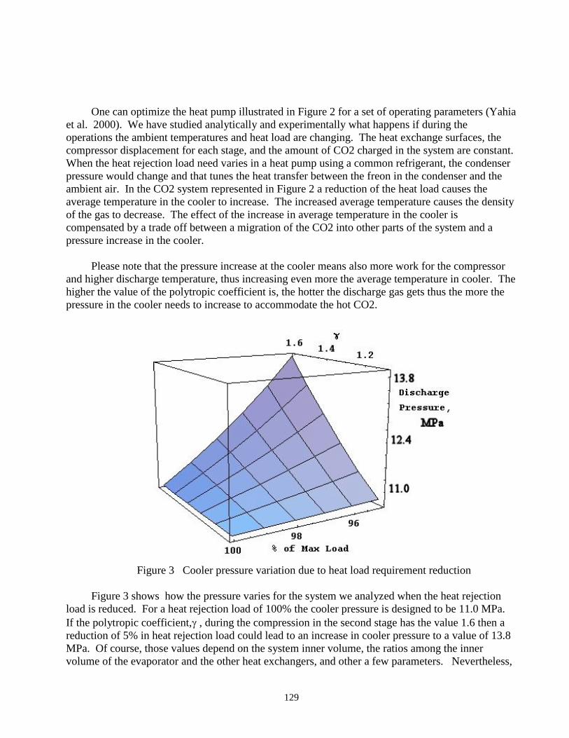
Please note that the pressure increase at the cooler means also more work for the compressor
and higher discharge temperature, thus increasing even more the average temperature in cooler. The
higher the value of the polytropic coefficient is, the hotter the discharge gas gets thus the more the
pressure in the cooler needs to increase to accommodate the hot CO2.
Figure 3 Cooler pressure variation due to heat load requirement reduction
Figure 3 shows how the pressure varies for the system we analyzed when the heat rejection
load is reduced. For a heat rejection load of 100% the cooler pressure is designed to be 11.0 MPa.
If the polytropic coefficient, , during the compression in the second stage has the value 1.6 then a
reduction of 5% in heat rejection load could lead to an increase in cooler pressure to a value of 13.8
MPa. Of course, those values depend on the system inner volume, the ratios among the inner
volume of the evaporator and the other heat exchangers, and other a few parameters. Nevertheless,
130
one can see that the cooler pressure variation can be substantial in the case of a high value of the
polytropic coefficient during the compression.
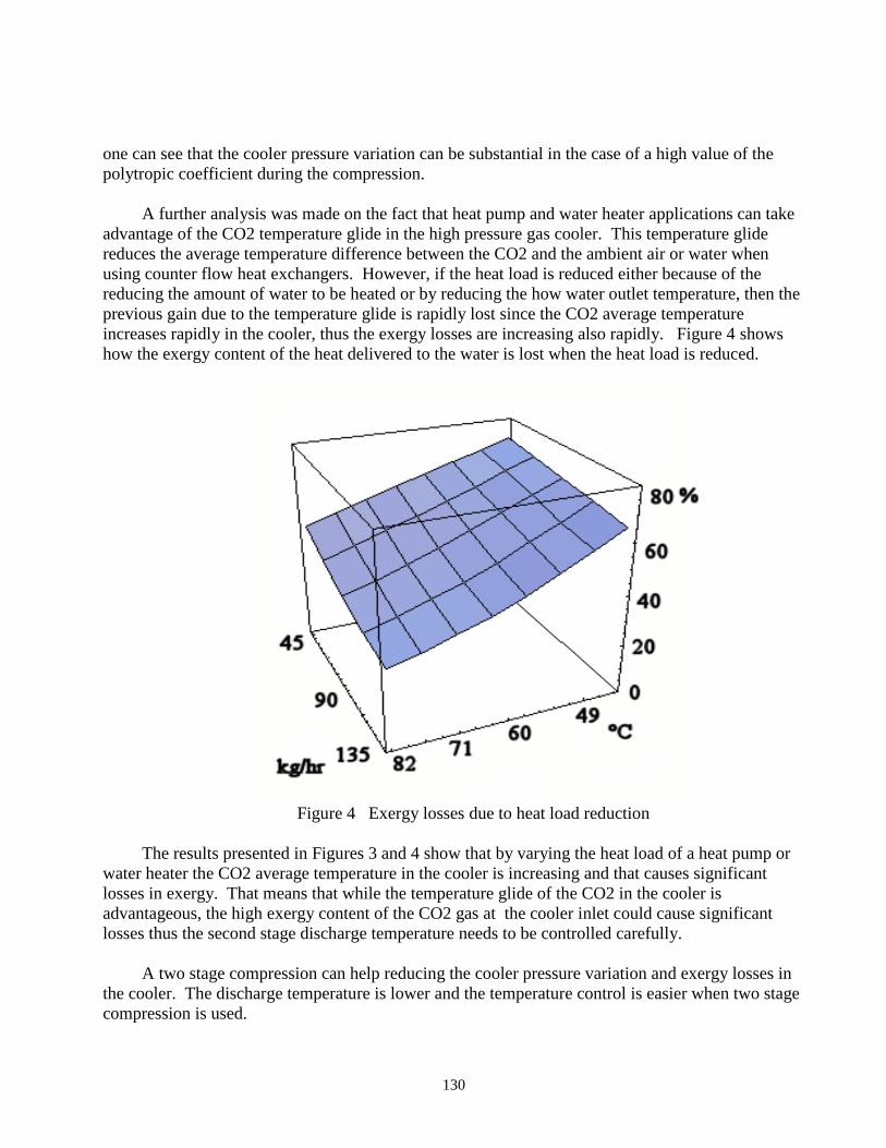
A further analysis was made on the fact that heat pump and water heater applications can take
advantage of the CO2 temperature glide in the high pressure gas cooler. This temperature glide
reduces the average temperature difference between the CO2 and the ambient air or water when
using counter flow heat exchangers. However, if the heat load is reduced either because of the
reducing the amount of water to be heated or by reducing the how water outlet temperature, then the
previous gain due to the temperature glide is rapidly lost since the CO2 average temperature
increases rapidly in the cooler, thus the exergy losses are increasing also rapidly. Figure 4 shows
how the exergy content of the heat delivered to the water is lost when the heat load is reduced.
Figure 4 Exergy losses due to heat load reduction
The results presented in Figures 3 and 4 show that by varying the heat load of a heat pump or
water heater the CO2 average temperature in the cooler is increasing and that causes significant
losses in exergy. That means that while the temperature glide of the CO2 in the cooler is
advantageous, the high exergy content of the CO2 gas at the cooler inlet could cause significant
losses thus the second stage discharge temperature needs to be controlled carefully.
A two stage compression can help reducing the cooler pressure variation and exergy losses in
the cooler. The discharge temperature is lower and the temperature control is easier when two stage
compression is used.
131
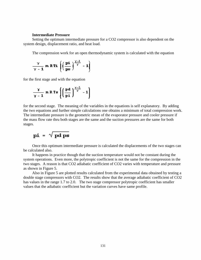
Intermediate Pressure
Setting the optimum intermediate pressure for a CO2 compressor is also dependent on the
system design, displacement ratio, and heat load.
The compression work for an open thermodynamic system is calculated with the equation
for the first stage and with the equation
for the second stage. The meaning of the variables in the equations is self explanatory. By adding
the two equations and further simple calculations one obtains a minimum of total compression work.
The intermediate pressure is the geometric mean of the evaporator pressure and cooler pressure if
the mass flow rate thru both stages are the same and the suction pressures are the same for both
stages.
Once this optimum intermediate pressure is calculated the displacements of the two stages can
be calculated also.
It happens in practice though that the suction temperature would not be constant during the
system operations. Even more, the polytropic coefficient is not the same for the compression in the
two stages. A reason is that CO2 adiabatic coefficient of CO2 varies with temperature and pressure
as shown in Figure 5.
Also in Figure 5 are plotted results calculated from the experimental data obtained by testing a
double stage compressors with CO2. The results show that the average adiabatic coefficient of CO2
has values in the range 1.7 to 2.0. The two stage compressor polytropic coefficient has smaller
values that the adiabatic coefficient but the variation curves have same profile.

132
Figure 5.
The smaller values of the polytropic coefficient during the compression compared to the
adiabatic coefficient are caused by the cooling of the CO2 gas during the compression and by
internal gas leaks.
The analysis of the discharge pressure showed the importance of controlling the value of the
discharge temperature of the second stage. Discharge temperature can be easily controlled by the
suction temperature. However, once an optimum intermediary pressure is calculated and the
displacement is calculated for each compressor stage, a change of the suction temperature of the
second stage would have an impact on the intermediate pressure. Figure 6 shows the results of a
parametric study of the effect of varying the second stage suction. This effect is studied for several
polytropic coefficients since the value of the polytropic coefficent varies with the discharge pressure
and can also vary with the compressor volumetric efficiency and internal heat transfer specific
design. The pressure coefficient plotted in Figure 6 correct the value of the intermediate pressure as
calculated as a geometric mean of the evaporating and cooler pressures.
Figure 6 shows that by increasing the second stage suction temperature the intermediate
pressure would decrease by 40% compared to the value calculated by the geometric mean of the
evaporator and cooler pressure. A temperature reduction does not cause that much of a change in
intermediate pressure. An isotherm compression has a polytropic coefficient with value 1. These
results show that for a polytropic coefficient closer to 1 the intermediate pressure experiences larger
variation when the suction temperature changes.

133
Figure 6 Intermediate pressure correction coefficient
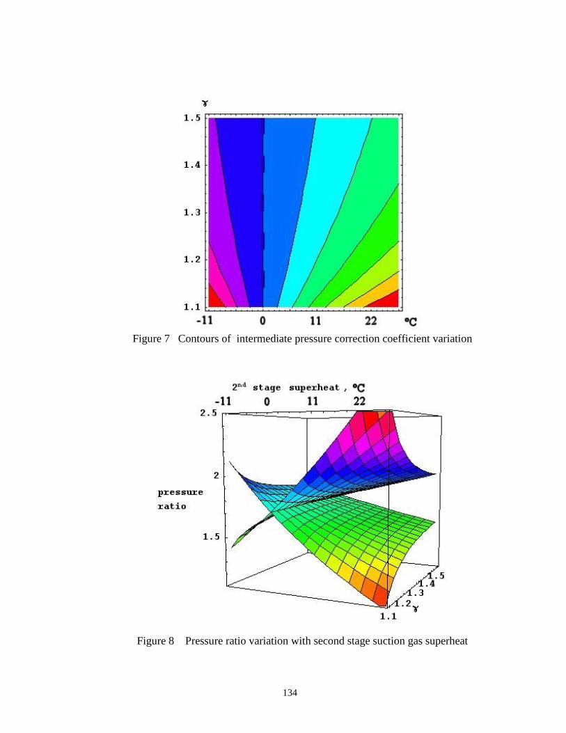
Figure 7 shows the contours of the surface plotted ion Figure 6. The dashed line in Figure 7
outlines the points corresponding to the optimum intermediate pressure when the second stage
suction temperature has the value as the first stage suction gas.
The change in intermediate pressure has a direct effect on the compression ratio for each stage.
Figure 8 shows the variation of the pressure ratio for each stage with the second stage suction
temperature and the polytropic coefficient variation. Both stages are assumed to have same value
for the polytropic coefficient for the results plotted in Figure 8.
134
Figure 7 Contours of intermediate pressure correction coefficient variation
Figure 8 Pressure ratio variation with second stage suction gas superheat
135
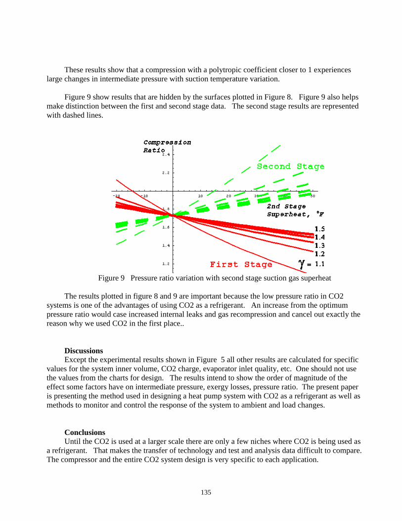
These results show that a compression with a polytropic coefficient closer to 1 experiences
large changes in intermediate pressure with suction temperature variation.
Figure 9 show results that are hidden by the surfaces plotted in Figure 8. Figure 9 also helps
make distinction between the first and second stage data. The second stage results are represented
with dashed lines.
Figure 9 Pressure ratio variation with second stage suction gas superheat
The results plotted in figure 8 and 9 are important because the low pressure ratio in CO2
systems is one of the advantages of using CO2 as a refrigerant. An increase from the optimum
pressure ratio would case increased internal leaks and gas recompression and cancel out exactly the
reason why we used CO2 in the first place..
Discussions
Except the experimental results shown in Figure 5 all other results are calculated for specific
values for the system inner volume, CO2 charge, evaporator inlet quality, etc. One should not use
the values from the charts for design. The results intend to show the order of magnitude of the
effect some factors have on intermediate pressure, exergy losses, pressure ratio. The present paper
is presenting the method used in designing a heat pump system with CO2 as a refrigerant as well as
methods to monitor and control the response of the system to ambient and load changes.
Conclusions
Until the CO2 is used at a larger scale there are only a few niches where CO2 is being used as
a refrigerant. That makes the transfer of technology and test and analysis data difficult to compare.
The compressor and the entire CO2 system design is very specific to each application.

136
The efficiency of the system is important but it is premature to work on optimizing this
objective function unless other driving forces are supporting the use of that specific CO2
application.
CO2 properties have large variations about the critical point as well as in the gas domain.
Load variations cause refrigerant migration in the system and pressure variations in the gas cooler.
Means to control the charge inventory are important in CO2 systems.
A two stage compressor provides an additional degree of freedom that helps controlling the
capacity of the CO2 system: the second stage suction temperature.
The compression polytropic coefficient is a factor to be used in the design of the CO2 system
response to ambient and load changes. A thermal design of the CO2 compressor is recommended
having this factor in mind.
References
1. Groll E., Cohen R. 2000 Review of recent Research on the Use of CO2 for Air
Conditioning and Refrigeration, Clima /Napoli World Congress – Napoli (I), pp. 1- 15.
2. Beaver A., Yin J., Bullard C. W., Hrnjak P. S. 1999 Experimental and model study of
the eat pump/air conditioning systems based on transcritical cycle with, 20th International
Congress of Refrigeration, IIR/IIF, Sydney, , pp. 1- 8.
3. Billiard F. The Case for Using Carbon Dioxide as a Refrigerant
4. Hussels U. 2000 FMEA of CO2 Air Conditioning Systems, SAE 2000 Automotive
Alternative Refrigerant Systems Symposium July 11-13, Scottsdale, AZ
5. Atkinson W. 2000 The Need to Establish SAE Documents for Alternate Refrigerants,
SAE 2000 Automotive Alternative Refrigerant Systems Symposium July 11-13, Scottsdale, AZ
6. Manole D. 2002 Modulation Techniques - Variable Speed Compressor – Measurements,
ASHRAE Congress, Atlantic City, NJ, Jan 15,
7. Jacobsen A 1995 Energy Optimization of refrigeration Systems, The Technical
University of Denmark, Ph.D. Thesis March
8. Yahia B.M, Mann C., Meurillon P. 2000 Optimisation of the CO2 A/C system: The Gas
Cooler effect, SAE 2000 Automotive Alternative Refrigerant Systems Symposium July 11-13,
Scottsdale, AZ