critical analysis of the britannia · pdf file · 2012-09-17a critical analysis of...
TRANSCRIPT
1
S. M. Collingwood – [email protected]
A CRITICAL ANALYSIS OF THE BRITANNIA BRIDGE, WALES
S. M. Collingwood1
1 Undergraduate Student - University of Bath
Abstract: An overview of the re-design and construction of The Britannia Bridge following the deterioration of the
original structure due fire damage. Emphasis is placed upon the difficulties in constructing a new bridge around an
existing one, whilst trying to keep the bridge open for use. The aesthetic properties of the bridge are analysed by
Leonhardt’s 10 rules. The loading on the main steel arch spans are considered in respect to BS 5400 during various
stages of the reconstruction.
Keywords: Britannia, arch , truss, railway
1 Introduction
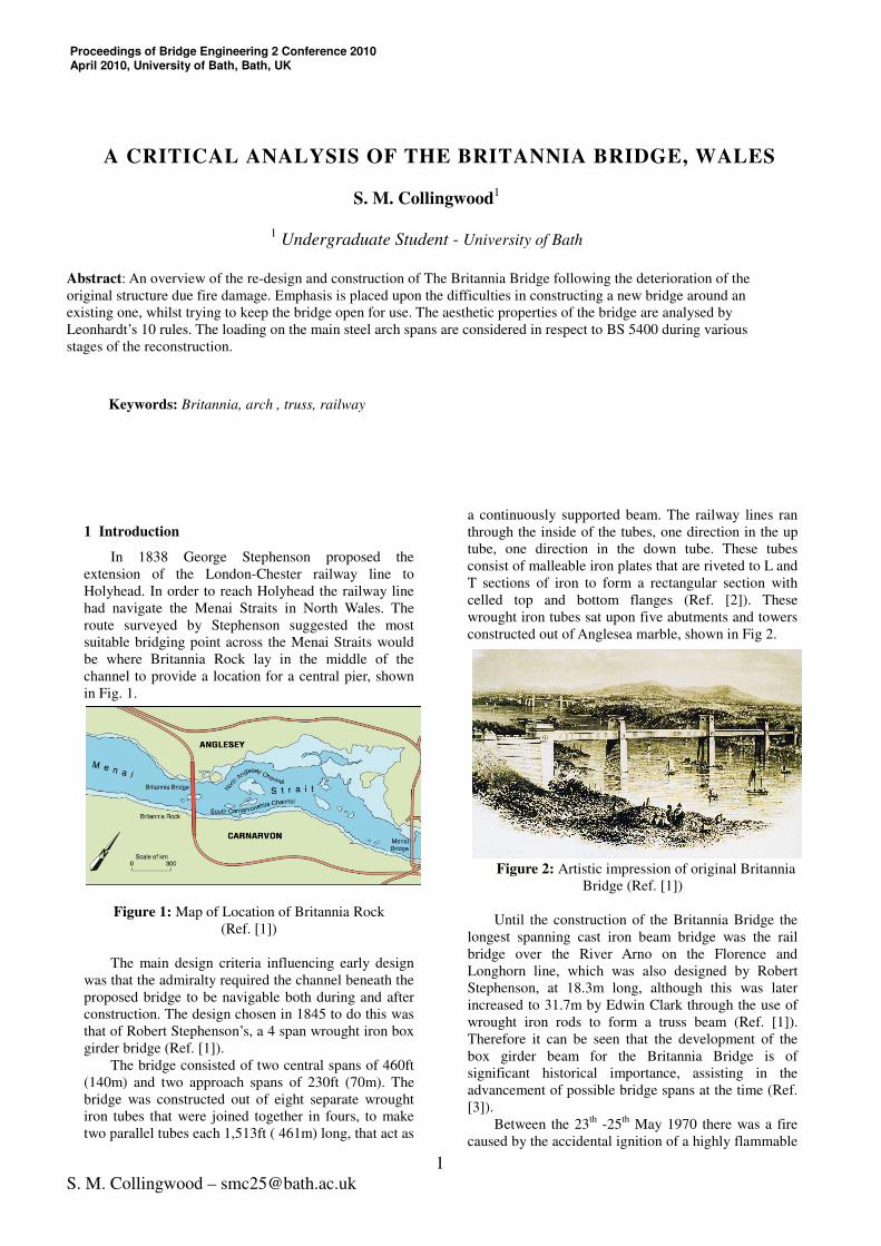
In 1838 George Stephenson proposed the
extension of the London-Chester railway line to
Holyhead. In order to reach Holyhead the railway line
had navigate the Menai Straits in North Wales. The
route surveyed by Stephenson suggested the most
suitable bridging point across the Menai Straits would
be where Britannia Rock lay in the middle of the
channel to provide a location for a central pier, shown
in Fig. 1.
Figure 1: Map of Location of Britannia Rock
(Ref. [1])
The main design criteria influencing early design
was that the admiralty required the channel beneath the
proposed bridge to be navigable both during and after
construction. The design chosen in 1845 to do this was
that of Robert Stephenson’s, a 4 span wrought iron box
girder bridge (Ref. [1]).
The bridge consisted of two central spans of 460ft
(140m) and two approach spans of 230ft (70m). The
bridge was constructed out of eight separate wrought
iron tubes that were joined together in fours, to make
two parallel tubes each 1,513ft ( 461m) long, that act as
a continuously supported beam. The railway lines ran
through the inside of the tubes, one direction in the up
tube, one direction in the down tube. These tubes
consist of malleable iron plates that are riveted to L and
T sections of iron to form a rectangular section with
celled top and bottom flanges (Ref. [2]). These
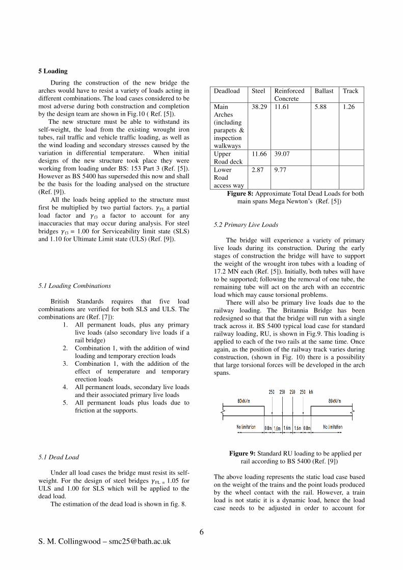
wrought iron tubes sat upon five abutments and towers
constructed out of Anglesea marble, shown in Fig 2.
Figure 2: Artistic impression of original Britannia
Bridge (Ref. [1])
Until the construction of the Britannia Bridge the
longest spanning cast iron beam bridge was the rail
bridge over the River Arno on the Florence and
Longhorn line, which was also designed by Robert
Stephenson, at 18.3m long, although this was later
increased to 31.7m by Edwin Clark through the use of
wrought iron rods to form a truss beam (Ref. [1]).
Therefore it can be seen that the development of the
box girder beam for the Britannia Bridge is of
significant historical importance, assisting in the
advancement of possible bridge spans at the time (Ref.
[3]).
Between the 23th
-25th
May 1970 there was a fire
caused by the accidental ignition of a highly flammable
Proceedings of Bridge Engineering 2 Conference 2010 April 2010, University of Bath, Bath, UK

2
S. M. Collingwood – [email protected]
timber joint, that was covered in hessian tar, that joins
the wrought iron tubes with the stone entrance. The fire
spread vertically and set alight the roof canopy
designed to protect the tubing (Ref. [4]). Severe
damage took place with structural continuity of both
the up and down tubes broken over the central 3 towers
and severe sagging was observed. There were also
signs of vertical corrugations of the plates on the side
of the bridge.
The bridge was considered unsafe and all rail
traffic was suspended. (Ref. [5]).
2 Design Considerations
One of the main problems with the Britannia
Bridge was the breaking of the cast iron races guiding
the roller and ball bearings carrying the tubes. There
were grave concerns that the tubes would slip off its
bearings and into the channel. The engineers involved
with the redesign had the objectives of restoring the
rail traffic at the earliest opportunity and the safe
removal of the damaged wrought iron tubes, but
without generating unnecessary construction costs
(Ref. [5]).
The removal of the damaged tubes was a key
consideration. In order to remove the tubes in their
entirety at least two of the largest floating cranes
available at the time would have been required and the
operation would have to be conducted in an area of
water with greatly fluctuating tides. It was decided that
this method posed too many risks and costs. The option
of reverse jacking the tubes back down the slots in the
tower used to raise them was considered. But it was
calculated that the tubes in their present condition
would be unable to withstand the process (Ref. [5]).
It was concluded that the new structure must be
able to fully support the existing tubes, so that they
may be dismantled and removed in sections.
The Welsh Office for the Department of the
environment had shown interest in the redesign
incorporating an upper road deck carrying a relief road
for the over congested Menai Bridge, shown on Fig.1.)
The selected method for achieving the above
considerations would be to build arches underneath the
main spans, making use of the undamaged piers and
towers. The approach spans would be replaced with
new box girder spans, shown in Fig. 3.
The main design consideration left was to be the
construction material of the arch, be it steel or
concrete. Steel was preferred on the basis that it could
be prefabricated off-site and floated in for quick
construction. Steel would provide a lighter design that
would allow more economical abutments to be
designed. At the time British Steel also promised to
heavily prioritize steel construction for the bridge (Ref.
[5]).
Figure 3: Photograph of the New Steel arch truss
design (Ref. [6])
3 Design
It was decided that the bridge would consist of a
two spandrel arch. The arch would be constructed out
of steel box sections and the truss elements out of H-
sections. For ease of construction all the arches would
be constructed out of 22 inch flange lengths and 42
inch web lengths, the thickness out of the steel would
vary between 1.25-1.75 inches thick. The railway
would run a single track on one side of the lower deck
where the original tubes once were, with a concrete
upper road way for the road traffic, see Fig. 4.
Figure 4: Section of arch at mid-span (in direction of
Britannia Tower) (Ref. [5])

3
S. M. Collingwood – [email protected]
4 Aesthetics
One of the factors also affecting the design of the
new bridge was its aesthetic qualities. The engineers
working on the project felt that due to the fire damage,
they would be unable to restore the bridge to a similar
outward appearance. One of the important aesthetic
considerations of the original bridge was the increasing
depth of the box girder sections from the sides towards
the center (Ref. [5]).
The original bridge had been set in the landscape
for 100 years and it was important that the new
Britannia Bridge was sympathetic towards the old,
maintaining the character it had developed.
In the 20th
Century Fritz Leonhardt developed ten
areas of aesthetics that need to be considered when
designing a bridge to ensure that it is not considered
objectionable (Ref. [7]).
4.1 Fulfillment of Function
Leonhardt proposed that the bridge should clearly
be shown to fulfill its function. The purpose of the new
Britannia Bridge was to re-establish the rail
connections across the Menai Straits and provide a new
road crossing. The bridge clearly has achieved this, it is
plain to see that the vertical loads are transmitted
through the bridge deck to the truss elements that
transfer the load to the steel arch. One misconception
could be that the horizontal thrust from the arches is
resisted by the masonry towers. This is not the case and
the load is transferred via reinforced concrete down
into the bedrock.
4.2 Proportions of the Bridge
It was also put forward by Leonhardt that a bridge
required balance between its masses and voids, light
and shadows, but also in its spans and depths. The
Britannia Bridge has open spandrels that are in stark
contrast to the masonry towers. These masonry towers
look heavy by modern standards as they are the
original towers from the original bridge .The arch
sections and the lower deck also looks heavy in
relation to the other elements in the structure. This may
be because they have the additional redundant capacity
to carry the excess loading of the original wrought iron
tubes. But as they are the main loading bearing
elements it doesn’t look incongruous. There is a good
balance between the shadow creating by the different
structural layers and the light that it allows through.
4.3 Order within the structure
If a bridge has a lot of lines and edges it can
become a mental disquiet to the beholder (Ref. [7]).
This is a drawback of the truss type construction. When
it is viewed from an angle it has a high order with lots
of edges and lines intersecting making it look untidy.
4.4 Refinement of Design
Subtle extra details can greatly improve the overall
aesthetics of the structure. In this case the use of
tapering columns to stop the illogical impression that
the top of a column is wider than the base. The
masonry towers taper from 62ft by 52ft 5 inches and
the bottom to 55ft by 32ft underneath the level of the
original tubes (Ref. [2]) in order to create this
impression. There is also detailing at the top of the
towers, as shown by fig 5, designed to make the top of
the towers look more refined. There are two limestone
lions at both ends of the bridge, purely for decorative
purposes, and an example of Victorian grandeur.
Figure 4: Artists View of the abutment area (Ref. [1])
The additional new structure contains little refinement
as it focus was more upon speed and ease of
construction
4.5 Texture
The variety of textures created by material choices
can be beneficial to the appeal of a bridge. The
weathered masonry piers have a rough and complex
texture that makes them interesting. Similarly the truss
contains a large number of bolts that upon inspection
provide novel textures but when viewing from a
distance it isn’t possible to see these subtleties. The
concrete elements appear smooth and uninteresting
from a viewing distance.
4.6 Colour
Colour can be used to highlight or detract from
elements of a bridge to make them appear thinner or
more noticeable. The arch and lower bridge deck, as
discussed earlier, appear heavy but this is somewhat
offset by the whiter appearance of them that makes
them appear lighter.

4
S. M. Collingwood – [email protected]
4.7 Character
The original Britannia Bridge had a lot of
character due to its historical value. The loss of the
original box section appearance and continuous beam
function could therefore be described as diminishing
the bridge’s character. However, the final design
chosen for the rebuild bears a striking resemblance to
an initial design proposed by Thomas Telford and
Rennie, Fig. 5. The proposal anticipated spanning the
two main sections with cast iron arches, although this
was rejected on the basis that it impeded the navigation
criteria set out by the admiralty (Ref. [1])
Figure 5: Artistic Impression of Telford and Rennie
(Ref. [1])
The bridge as it stands now can be viewed as a
composite of many different ideas across 150 years and
this gives it a tremendous amount of character.
4.8 Integration into the Environment
The modern bridge upholds many of the original
aspects of the bridge which has been part of the
environment for a long as there is living memory. The
bridge now serves the needs to the local and national
communities to a higher level with the addition of the
road. It is sufficiently in keeping with its previous
incarnation to be considered integrated with its
environment.
4.9 Complexity
In order for a bridge to be visually stimulating it
needs a degree of complexity which may appear
contradictory to other principles such as having low
order. It is important that a balance is met so that a
bridge requires time to appreciated without appearing
chaotic. The Britannia Bridge has many different
elements and can be seen as complex with different
structural mechanisms used on different spans. It is
also a double decker bridge that makes it more
complicated. Though interesting as discussed in the
order sections it can be confusing with too much going
on.
4.10 Nature
Over time nature has developed some of the most
beautiful and brilliant structural designs. Leonhardt
proposed that by incorporating elements of nature into
the structural design you would arrive at an elegant
solution. However, this is not the case for the Britannia
Bridge, which lacks distinctly in a natural theme but
rather pays homage to the efficiency and functionality
necessary for continuing the second industrial
revolution occurring at the time.
4.11 Aesthetics Summary
The rules outlined by Leonhardt are not a
comprehensive set of absolute principles that will
produce a beautiful bridge every time aesthetics are
subjective to the critical beholder. The Britannia Bridge
follows several of Leonhardts rules but is truer to
function and its original heritage which was created
before these rules of aesthetics were derived and
documented.
4 Construction Method
As mentioned previously the arch units were
constructed out of steel and prefabricated offsite. The
arches were prefabricated at the harbor of Port
Dinorwig, which lies 2 miles away. At the harbor 8
erection bays were constructed so that the arches could
be constructed on heavy gauge bogies and transferred
onto purpose built pontoons that could be attached to
the dock wall at low tide.
These pontoons were then transported to site by
being pulled by 2 tugs. It was timed so that they arrived
onsite during slack water to try and mitigate the effects
of the strong tide, which would make accurate
construction difficult. Once onsite, the pontoons were
moored into position and attached by mooring lies to
the bridge itself and purposely positioned buoys.
On the next slack tide a lifting gantry raised the
arches into place. Construction of the arches used a
cantilever method of construction. The half arches
attached to Britannia Tower were tied back to together

5
S. M. Collingwood – [email protected]
with steel rods to each other so not to produce any
moments. The half arches on the landward towers were
tied to the approach spans.
The arches were designed so they could both be
closed into 3 pin arches at the same time. If one of the
spans was completed first and its tying back force
released it was calculated that the horizontal force
generated would cause a high shear load at the mid
span and this would cause the failure the bottom
bracing cord bearings that were designed to only rotate
sufficiently to allow both 3 pin arches to form 2 pin
arches as shown in Fig. 6 (Ref. [8]).
Figure 6: Construction sequence of the arches (Ref.
[5])
In order to produce suitable dry conditions within
which to build the concrete foundations for the arches,
sheet pile cofferdams were constructed around the
bases of the Britannia and Anglesey towers and the
water pumped away. Simpler trench sheeting was then
deemed suitable to have the same effect at Caernarvon
Tower due to different ground conditions.
Whilst the arches were being constructed the
openings in the towers were being increased to make
space for the upper road deck and conform to new
British rail clearances. The deck for the steel arch was
laid in prefabricated units.
Flat jacks where used to attempt to uniformly
transfer the load of the existing tubes on to the new
structure. It was determined that once this was
completed that the bottom section of the existing tubes
had sufficient bearing capacity as to be able to carry
the railway. The railway was temporarily resumed
through the down tube.
Meanwhile the up tube was being dismantled. A
railway line was also run through the up tube that
carried a heavy trestle tower driven by a locomotive,
see Fig.7. The tubes were cut into 15 ft long pieces and
attached to the locomotive trestle tower. The roof and
sides of the tubes were then cut free of the bottom
flange, whereupon the weight transferred to the trestle
tower. The loose components were then transferred
along the track to the ends where they could be safely
removed.
The up tube could then be replaced with a new rail
deck. The railway was then transferred to the newly
completed track and the down tube was dismantled in a
similar fashion.
Once the railway was complete and the old tubes
removed, the upper road deck was constructed out of
concrete (Ref. [8]).
Figure 7: Picture of the dismantling of wrought iron
tubes (Ref. [5])
6
S. M. Collingwood – [email protected]
5 Loading
During the construction of the new bridge the
arches would have to resist a variety of loads acting in
different combinations. The load cases considered to be
most adverse during both construction and completion
by the design team are shown in Fig.10 ( Ref. [5]).
The new structure must be able to withstand its
self-weight, the load from the existing wrought iron
tubes, rail traffic and vehicle traffic loading, as well as
the wind loading and secondary stresses caused by the
variation in differential temperature. When initial
designs of the new structure took place they were
working from loading under BS: 153 Part 3 (Ref. [5]).
However as BS 5400 has superseded this now and shall
be the basis for the loading analysed on the structure
(Ref. [9]).
All the loads being applied to the structure must
first be multiplied by two partial factors. �FL a partial
load factor and �f3 a factor to account for any
inaccuracies that may occur during analysis. For steel
bridges �f3 = 1.00 for Serviceability limit state (SLS)
and 1.10 for Ultimate Limit state (ULS) (Ref. [9]).
5.1 Loading Combinations
British Standards requires that five load
combinations are verified for both SLS and ULS. The
combinations are (Ref. [7]):
1. All permanent loads, plus any primary
live loads (also secondary live loads if a
rail bridge)
2. Combination 1, with the addition of wind
loading and temporary erection loads
3. Combination 1, with the addition of the
effect of temperature and temporary
erection loads
4. All permanent loads, secondary live loads
and their associated primary live loads
5. All permanent loads plus loads due to
friction at the supports.
5.1 Dead Load
Under all load cases the bridge must resist its self-
weight. For the design of steel bridges �FL = 1.05 for
ULS and 1.00 for SLS which will be applied to the
dead load.
The estimation of the dead load is shown in fig. 8.
Deadload Steel Reinforced
Concrete
Ballast Track
Main
Arches
(including
parapets &
inspection
walkways
38.29 11.61 5.88 1.26
Upper
Road deck
11.66 39.07
Lower
Road
access way
2.87 9.77
Figure 8: Approximate Total Dead Loads for both
main spans Mega Newton’s (Ref. [5])
5.2 Primary Live Loads
The bridge will experience a variety of primary
live loads during its construction. During the early
stages of construction the bridge will have to support
the weight of the wrought iron tubes with a loading of
17.2 MN each (Ref. [5]). Initially, both tubes will have
to be supported; following the removal of one tube, the
remaining tube will act on the arch with an eccentric
load which may cause torsional problems.
There will also be primary live loads due to the
railway loading. The Britannia Bridge has been
redesigned so that that the bridge will run with a single
track across it. BS 5400 typical load case for standard
railway loading, RU, is shown in Fig.9. This loading is
applied to each of the two rails at the same time. Once
again, as the position of the railway track varies during
construction, (shown in Fig. 10) there is a possibility
that large torsional forces will be developed in the arch
spans.
Figure 9: Standard RU loading to be applied per
rail according to BS 5400 (Ref. [9])
The above loading represents the static load case based
on the weight of the trains and the point loads produced
by the wheel contact with the rail. However, a train
load is not static it is a dynamic load, hence the load
case needs to be adjusted in order to account for

7
S. M. Collingwood – [email protected]
Figure 10: Loading cases considered on the main
spans (Ref. [5])
impacts, oscillations and other dynamic effects the
loadings in
Fig. 9 must be multiplied by a dynamic factor, BS 5400
Clause 8.2.3. The dynamic factor can be seen in Figure
11 .
Figure 11: Dynamic factors according to BS 5400
(Ref. [9])
The length of the influence line for an arch
structure is half of its span (Ref. [9]). As the span of the
main arches in the Britannia Bridge is 134m,
evaluating fig. 8 produces a dynamic factor of 1.00.
The partial load factor for the rail primary and
secondary live loads, �FL, for the ULS under load
combination 1= 1.4, under load combination 2= 1,2
and under load combination 3= 1.2. For all SLS �FL
=1.0
The bridge will also be required to resist the
primary live loads of the road traffic. During the initial
design of the bridge the main traffic loading considered
was that of HA loading. The ratio of loading between
the road live loads and the dead load and the railway
live load combined was in the order of 1:7 and
therefore it was considered suitable to apply just HA
loading (Ref. [5]). The carriage way was considered to
have 3 notional lanes, as shown in Fig. 10.
HA Loading consists of a uniformly distributed
load (UDL) acting across the notional lanes as well as a
knife-edge load (KEL). For a HA UDL acting over the
arch span of 134m, the required magnitude is 20.9
kN/m per notional lane. The KEL per notional lane is
120kN placed in the most adverse conditions.
5.3 Secondary Live Loads
The railway loading will also produce several
secondary live loads such as lurching. Lurching is the
transfer of the live load from one rail to the other and is
taken into account by the dynamic factor.
Nosing is another secondary live load associated
with rail loadings. Nosing considers the lateral loading
a train may impart on a rail. It is represented by a

8
S. M. Collingwood – [email protected]
single point load of 100kN acting perpendicular to the
direction of the rail (Ref. [9]).
If there is curvature in the track the train may also
cause a loading due to centrifugal force, but this is not
the case as the track across the Britannia Bridge is
straight.
The longitudinal loading caused by braking and
traction forces can be evaluated from Table 18 in BS
5400 Part 2. The longitudinal load due to traction is
750kN applied in the direction of travel (Ref. [9]). The
braking forces can be evaluated from equation 1.
Braking Force = [20(L-7) + 250] (1)
= 2960kN
Therefore the maximum longitudinal load applied is
3710kN.
There are also secondary live loads associated with
HA loading. The longitudinal loading associated with
trucks is represented as a 8kN/m UDL across the width
of the notional lanes and a single 200kN point load.
The skidding of a vehicle is considered as a single 250
kN point load in any direction in one notional lane
only. Once again, as with rail loading, centrifugal
loading will not be applicable. Impact loading
considerations would also be investigated.
5.4 Wind Loading
The wind pressures will cause additional loading
on the structure that needs to be considered. The wind
pressures can cause transverse, longitudinal and uplift
loading. As shown by Fig. 9 the main concerns in this
design were those of transverse and longitudinal
loading, as uplift is unlikely due to the high self-weight
of the bridge.
5.4.1 Transverse wind loading
The maximum wind gust can be calculated from
equation 2.
Vc = vK1S1S2 (2)
Based upon factors taken from BS5400 vc for
Britannia Bridge can be evaluated as 68.9 m/s. The
transverse wind load can then be evaluated by equation
3.
Pt=qA1CD (3)
With
q=0.613vc2
(4)
The tranverse wind load is 3.2 MN for each of the main
spans.
5.4.1 Longitudinal wind loading
The longitudinal wind loading can be given by
equation 5.
Pv = qA3CL. (5)
By obtaining the factors from BS 5400 for the
Britannia Bridge this can be evaluated at 59kN.
5.5 Temperature Effects
The variation in effective temperature will cause
elements in the bridge to expand or contract. As the
members are held in place by one another this will
generate unwanted stresses and strains.
There are also stresses produced by a difference in
temperatures between elements. During construction of
the new bridge a variation of up to 20oc was measured
between elements in direct sunlight and shade. The
effect of temperature has been mitigated by the use of
expansion joints in both the rails and road deck above
the landside towers and Britannia tower (Ref. [5]).
5 Strength
The ULS and SLS for the above loadings were
considered for all stages of construction by the use of a
Finite Element package, Electronic Calculus
Incorporated (ECI) programs 201 and 631. Performing
initial 2D and the 3D analysis (Ref. [5]).
As mentioned previously the arches used in the
main spans were designed to act as a 2 pin arch. As the
dead load of the structure combined with rail and road
live loads are higher than any other load, it is possible
to estimate the present bending moments in the arch by
using load combination 1. As shown in Fig. 9, this load
combination will be applied both to the full-span and
half-span to see which produces the more critical
bending moment.
When the factored combination loading 1 was
considered on the arch structure loaded as a whole. The
maximum sagging moment that the arch has to resist
was 34.4 MNm, with a higher hogging moment of
38.8MNm. The bending moment diagram for the
structure is shown in Fig.12.

S. M. Collingwood – smc25@bat
Figure 12: Bending Moment diagram with Load
Combination 1applied across whole span
It was interesting to see that the loading on the
structure became more critical when the live loading
was only applied to half the structure. In this case the
sagging moment increased to 49.1 MNm
hogging moment to the most critical 67.4 MNm, as
seen in Fig.11.
Figure 13: Bending Moment diagram with Load
Combination 1applied with permanent
whole span and live loads across half the span
6 Natural Frequency
The natural frequency of a bridge of this
magnitude is very important. If the dynamic loading of
the bridge from the railway track is similar
the natural frequency, unwanted oscillations can occur.
The same effect can occur from the variation in wind
forces acting on the structure. These oscillations
magnify the effects of a load and can cause
catastrophic failure.
9
th.ac.uk
Bending Moment diagram with Load
across whole span
It was interesting to see that the loading on the
structure became more critical when the live loading
was only applied to half the structure. In this case the
sagging moment increased to 49.1 MNm and the
hogging moment to the most critical 67.4 MNm, as
Bending Moment diagram with Load
loads across the
and live loads across half the span
bridge of this
very important. If the dynamic loading of
the bridge from the railway track is similar to that of
unwanted oscillations can occur.
ariation in wind
These oscillations
magnify the effects of a load and can cause
7 Durability
The steel Britannia Bridge was con
risk to attack by corrosion d
bridge to the sea and the high winds
further increased. The designers thought that there
might also be an issue that some of the steelwork
would be unable to be accesse
completed to perform any maintenance required.
All the steel work used in the bridge underwent
high quality grit blasting to ensure all
the steel mill was removed. The steel was then als
treated by being sprayed with aluminum.
There are a large number of bolted connections in
the Britannia Bridge. These bolted connections are
subject to fatigue. The repeated cyclic loading of the
bridge, due to its dynamic live loading, will constantly
place the connections under a varying amount of stress.
This can cause the bolts to loosen and allow more
flexibility than has been allowed for. The result of this
is that the deflections at serviceability limit state can be
higher than predicted causing dif
track alignment.
8 Foundations
The foundations for the arch springings are
designed to transmit the thrust from the arch into the
bedrock. The foundations are heavi
concrete blocks that transfer
mixture of shear and bending. The
bases of the masonry towers was
This was done by exploratory drilling. Any cavities
discovered were filled by pressure grouting. The
bearing capacity of the bedrock
[5]) .
9 Cost
It is estimated that the reconstruction of the bridge
to make it safe for rail traffic was £5.5 million. The
vast majority of that was spent on the contractor’s
building cost. It cost an addition £4.75
construct the upper road deck and build the new
approach ways to divert the traffic
10 Future Changes
During 2006 Atkins ltd was tasked by the Welsh
Assembly Government to determine different options
for increasing the road traffic carrying capacity of the
Britannia Bridge., which they undertook in November
2007.
ritannia Bridge was considered to be at
due to the proximity of the
bridge to the sea and the high winds this likelihood is
The designers thought that there
might also be an issue that some of the steelwork
would be unable to be accessed once the bridge was
completed to perform any maintenance required.
All the steel work used in the bridge underwent
ality grit blasting to ensure all rust and dirt from
the steel mill was removed. The steel was then also
treated by being sprayed with aluminum.
a large number of bolted connections in
the Britannia Bridge. These bolted connections are
subject to fatigue. The repeated cyclic loading of the
due to its dynamic live loading, will constantly
ace the connections under a varying amount of stress.
This can cause the bolts to loosen and allow more
flexibility than has been allowed for. The result of this
is that the deflections at serviceability limit state can be
higher than predicted causing difficulties with the rail
The foundations for the arch springings are
designed to transmit the thrust from the arch into the
bedrock. The foundations are heavily reinforced
that transfer the load down by a
mixture of shear and bending. The condition of the
bases of the masonry towers was also investigated.
This was done by exploratory drilling. Any cavities
discovered were filled by pressure grouting. The
bearing capacity of the bedrock was 1180kN/m2 (Ref.
It is estimated that the reconstruction of the bridge
make it safe for rail traffic was £5.5 million. The
vast majority of that was spent on the contractor’s
building cost. It cost an addition £4.75 million to
construct the upper road deck and build the new
approach ways to divert the traffic
During 2006 Atkins ltd was tasked by the Welsh
Assembly Government to determine different options
for increasing the road traffic carrying capacity of the
Britannia Bridge., which they undertook in November

10
S. M. Collingwood – [email protected]
Atkins reported that they had 3 main options, which
were, firstly to try and widen the existing carriage way
to increase the capacity of the existing structure.
Alternatively, to construct a new multi-span structure
out of concrete alongside the existing bridge or
construct a new single span cable-stayed bridge next to
Britannia Bridge.
These options were than subject to a public
consultation exercise to investigate how the public felt
about the matter. It was interesting to see the public’s
primary concern was that the reduction of current
congestion and that safety was the next most important
factor. The history and heritage of the bridge was only
the third most important factor to the public in design
considerations. 22% of people preferred the option to
widen the existing bridge. 70% of people preferred the
option of constructing a new bridge alongside the
existing one (Ref. [10]).
Recommendations
Given the already extensive history of the Britannia
Bridge it seems illogical to construct a new bridge
alongside it to deal with the issues of congestion. If the
bridge can feasibly be widen as proposed by Atkins it
would add to the already extraordinary history of the
bridge rather than conflicting with it aesthetically.
References
[1] RYALL, M.J, 1999. Britannia Bridge: from
concept to construction, Proc. Instn Civ. Engrs,
Civ. Engng 132, May/August 132-146, Paper
11736.
[2] DEMPSEY G. DRYDALE, 1864. Tubular and
other Iron Girder Bridges, particulary describing
the Britannia and Conway Tubular Bridges, Virtue
Brothers and Co. London. Reprinted 1970,
Redwood Press Limited, London.
[3] INTITUTE OF CIVIL ENGINEERS, 2008. ICE
manual of Bridge Engineering, Second Edition,
Thomas Telford Ltd, London.
[4] CAERNARVONSHIRE COUNTY COUNCIL
FIRE BRIGADE & ANGELESEY COUNTY
COUNCIL FIRE DEPARTMENT, 1970. A Joint
Report on A Fire in The Britannia Tubular
Bridge, Menai Straits On Saturday – May 23rd
1970.
[5] H C HUSBAND, 1975. Reconstruction of the
Britannia Bridge Part 1: Design, Proc. Instn Civ.
Engrs, 58, Feb 25-66.
[6] Britannia Bridge In: travel web shots [Online]
Available from URL:
http://travel.webshots.com/photo/23132172800862
15107EfXcIY [Accessed 5th March 2011]
[7] TIM IBELL. Bridge Engineering, Department of
Architecture and Civil Engineering, University of
Bath.
[8] R W HUSBAND, 1975. Reconstruction of the
Britannia Bridge Part 2: Construction, Proc. Instn
Civ. Engrs, 58, Feb 25-66.
[9] BS5400: 2006. Steel , Concrete and Composite
Bridges. BSI
[10] WELSH ASSEMBLEY GOVERNMENT, 2008.
A55 Britannia Bridge – Release of the results of
the recent public consultation exercise.