critical evaluation of low-energy ship … critical evaluation of low-energy ship collision-damage...
TRANSCRIPT

SSC-284
CRITICAL EVALUATIONOF LOW-ENERGY SHIPCOLLISION-DAMAGE
THEORIES AND DESIGNMETHODOLOGIES
VOLUME 1: EVALUATIONAND RECOMMENDATIONS
ThB document has baan approvedfor public release end salq its
distribution is unlimited.
SHIP STRUCTURE COMMITIEE
1979

YZE * Zzs’mNJdse9sy3&Im comIrmd
Unikd Shria3Ge&gid SJrveyAme-icm&mlud.YIi@nq
~tttdutue
An InteragencyAdvisoryCommiffea
DedicatedtoImprovingthe%-wture ofShips
SR-1237
APRIL 1979
Interest in structural protection from collision, grounding or strand-ing ranges from nuclear-powered vessel design to minor damage resultingin pollution. The interest involves economics, safety of life and prop-erty, and conservation of the environmentt.
In view of the existence of a body of prior research, the Ship Structure
Committee has conducted a project to critically evaluate this prior effortand determine whether at least one of the available design methods or acombination of methods can be used with confidence for minimization ofcollision damage and protection of the vessel.
This is Volume I of the final report of the project and is being publishedto assist in developing a rational design approach for reducing low-energycollision effects. Volume 11 will contain an annotated bibliography.
c-’z-xiati~flRear Admiral, U. S . Coast Guard
Chairman, Ship Structure Commit tee

SSC-284
FINAL REPORT.
on
Project SR-1237
“CO1lision Damage and Stranding”
CRITICAL EVALUATION OF LOW-ENERGY
SHIP COLLISION-DAMAGE THEORIES
AND DESIGN METHODOLOGIES
VOLUME I : EVALUATION AND RECOMMENDATIONS
by
P. R. Van Mater, Jr.J. G. Giannotti
GIANNOTTI & BUCK ASSOCIATES, INC.
With contributions by
N. Jones andP. Genalis
under
Department of TransportationUnited States Coast Guard
Contract No. DOT-CG-63738-A
Th-b document has been approved for public release andsale; its distribution is unlimited?
U. S. Coast Guard HeadquartersWashington, D.C.
1979

TechnicalReportDocum.ntatie.Peg*
1,R.pe,tN.. I2.G...c”,..,AC..,,,.”N.. I3.R.., pi.n+,. C.,.l.gN..
‘SC-284–.1.4.1,,1.andS.b!,,l. F=-’kitical Evaluation of Low-Energy Ship Collision Damagerheoriesand Des<gn Methodologies. Volume I: 6.P.,1.,m,,,s0,s..,,.,,..cod.:ionand Recommendations
‘.R.Van Mater, Jr., J. Giannotti,N. Jones, P. Genali~9.P.,f.,m,.sOr,a,i..,b.Nmm.md Add,.,, 10, W.,k “.;, N.. (Trm,s)
;iannotti& Buck Associates, Inc.j711Sarvis Avenue, Suite 402 1I C.,,,,..,.,G,..,N..{iverdale,Maryland 20840 DoT-cG-63738-A
t>.Tw..1R-e.,,andP.,,edCov.,.d12.Sp.m,o,h,oAS...,Nom...dAdd,...— Technical Report:ommanda”t(G-FcP-2/71) 28/2/77 - 28/11781. S. Coast GuardcOOSeventh Street, S. W. 14.S...S..;.SAW.CVCod.Washington,D. C. ‘R-123715.S.ppl.m..,orrN.,..
;ontractmonitored by: Ship Research CommitteeNational Academy of SciencesWashington.D. c.
16.Ab,f,.Ict
This is Volume I of a two-volumereport describing the results of a Ship StructureCommittee study aimed at conductinga critical evaluationof low-energy ship colli-sion damage theories and design methodologies. Data sources on ship collisiondamage are identifiedincludingmodel experimentsand fdl scale informationobtainefran ship casualty records. The assumptionsmade by existing theories for analyzinglow enerw? collisionsare assessed a“d the collision energy absorptionmechanisms.are ranked.analysis tofor further
A method is proposed for extendingMinorsky’S“original high-energythe low-energyregime.research are made.
Recommendationsfor use of existing methods and
17.K.,W.,d, 18,O,,,fib.+io.S?.?.m.”tShip collisions This document has been approved forStructuralAnalysis public release and sale; its distributionStructuralDamage is unlimited.Ship StructuresStructuralFailures19,s.<.,,,”cl...,{.(.I*I,,.*..t) m. s.c.rit,cl.,,,!.(.I*h,.,.,.) 21.N.,.6P.,.. 22.Pri.*
Unclassified Unclassified 91I 1 1
‘wm DOT F 1700.7(8.72) ii

SHIP STRUCTURECOMMITTEE
The SHIP STRUCTJRECOMMITTEEis constitutedto prosecutea researchprogram to improvethe hull structuresof shipsand other marine structuresby an extensionof knowledgepertainingto design,materialsand methods ofconstruction.
RADM H. 3. BeIl (Chairman) Mr. M. PitkinChief, Officeof MerchantMarine AssistantAdministmtor for
Safety CommercialDevelopmentU. S. Coast Guard Headquarters MaritimeAdministration
Mr. P. M. Palermo ‘Mr.R. B. KrahlAssistant for Structures Chief, Branchof Marine Oil andNaval Ship EngineeringCenter Gas OperationsNaval Sea SystemsCoumand U. S. GeologicalSurvey
Mr. W. N. Hannan Mr. C. J. whitestoneVice President Chief EngineerAmericanBureau of Shipping MilitarySealiftCommand
LCDR T. H. Robinson,U. S. Coast Guard (Secretary)
SHIP STRUCTUP.ESUBCO!.MTTEE
The SHIP STRUCTURSSUBCOMMITTEEacts for the Ship StructureComaitteeon technicalmattersby providingtechnicalcoordinationfor thedeterminationof goals and objectivesof the program,and by evaluatingandinterpretingthe resultsin termsof structuraldesign,constructionandoperation.
U. S. COAST GUARD MILITARYSSALIFTCOhl14FJT
Cdr.J. C. CardLcdr S. H. DavisCapt C. B. GIUSDr. W. C. Dietz
NAVAL SEA SYSTEMScoMMAtm
Mr. R. ChiuMr. R. JohnsonMr. C. SorkinMr. J. B. O’Brien (ContractsAdmin.)
Mr. T. W. ChapmanMr. A. B. StavovyMr. D. SteinMr. J. Torresen
AFCSRICANBUFS4U OF
Dr. H. Y. JanMr. D. LiuMr. I. L. SternMr. S. G. Stiansen
SHIPPING
(Chairman)
MARITIhEADMINISTRATION U. S. GEOLCYXCALSURVEY
Mr. F, J. Dashnaw Mr. R. GiangerelliMr. N. O. Hammer Hr. J. Gregoq’Mr. F. SeiboldSir.M. Towma INIWW.TIONAL SHIP STRUCTURESCONGRESS
Prof. J. H. Evans - LiaisonNATIONALACADEMY OF SCIENCES
SHIP RLSEARCHCOMMITTEE AMERICAN IRON & STEEL INSTITUTE
Mr. O. H. Oakley - Liaison Mr. R. H. Sterne - Liaison
Mr. R. W. Rvmke - Liaison STATS UNIV. OF tiiWYORK M4RITLMECOLLEGE
SWIETY OF NAVAL ARCHITECTS& Dr. W. R. Porter - Liaison
MARINS ENGINEERS U, S. COAST GUARD ACADEMYMr. A. B. Stavovy. Liaison Capt W. C. Nolan - LiaisonWSLDING RESEARCHCOUNCIL U. S. NAVAL ACADEMY
Mr, K. H. ICoopman- Liaison Dr. R. Battacharyya- Liaison
U. S. MSRCHANT1#.RINEACADE~Dr. Chin-BeaKim - Liaison
iii
91,,, ,1,,:,,, 1,,,6 ~t L , $Pcctw
,J1’11111111111111:1!11111,,,,,] I i I 111~[[~11 ,,,),,,,,,,1,,,,,,,1,,,,,,,1,,,,,,,s,,,,‘I’llill !IIM II,!,1111,,1i,
! ,1!!,!!,,!,,,, 1! 4.!!,,,,!!!,, !,, ,,, ,,, ,,, ,,, ,,, ,,, ,,, ,, ,,, ,,, ,,, ,,, ,,, ,g 1/1 Ill Ill Ill ill 1(1 Ill Ill 1/1 1/1 Ill Ill 1]1 Ill Ill Ill 1(1 1]1~
, ,E , * ,.*
iv

TABLE OF CONTENTS
1.0
2.0
3.0
4.0
5.0
INTRODUCTION . . . . . . . . . . . . . . . . . . .
SCOPE AND OBJECTIVES . . . . . . . . . . . . . . .
REVIEW OF PAST AND CURKENT WORK IN LOW-ENERGY SHIPCOLLIS ION DAMAGE
3.1 GENERAL . . . . . . . . . . . . . . . . . . .
3.2 SDMNARY OF EXPERIMENTAL AND FULL-SCALE SHIP .COLLISION DATA
. . . . .
. . . . .
. . . . .
. . . . .
. . . . .
3.3 CRITICAL REVIEW OF EXISTING METHODS OF ANALYSIS . . . .
ASSESSMENT OF ADEQUACY ANc VALIDIT1’ OF THE EXISTING . . . .
LOW-ENERGY COLLISION DAMAGE THEORIES AND DESIGN METHODOLOGIES
4.1 VALIDITY OF THE ASSUMPTIONS MADE IN THE ROSENBIATT. . .
METHOD
4.2 APPLICABILITY OF THE LOW-ENERGY COLLISION DAMAGE. . . .THEORIES AND DESIGN METHODOLOGIES
4.3 SENSITIVITY AND RANKING OF SHIP COLLISION ENERGY. . . .ABSORPTION MECHANISMS
CONCLUSIONS AND RECOMMENDATIONS. . . . . . . . . .
5.1 GENERAL . . . . . . . . . . . . . . . . . . .
5.2c0NcLus10Ns . . . . . . . . . . . . . . . . .
5.3 RECOMMENDATIONS . . . . . . . . . . . . . . .
REFERENCES
APPENDICES
APPENDIx A -
APPENDIx B -
A SUMMARY OF GKSS COLLISION WORK
STATUS OF THE DEVELOPMENT OF THEOF STRUCTURAL RESPONSE OF ENERGY
BARRIERS AS OF DECEMBER 1977
. . . . .
. . . . .
. . . . .
. . . . .
PAGE
.
1
2
3-1
3-1
3-1
3-9
4-1
4-2
4-6
4-8
5-1
5-1
5-1
5-4
MATHEMATICAL MODELRESISTING COLLISION
v

APPENDIX C - EXTENSION OF MINORSXY ‘S ORIGINAL WORX TO THE LOW-ENERGY SHIP COLLISION REGION
APPENDIX D - CRITICAL REVIEW AND ASSESSMENT OF THE ASSUMPTIONS
IN THE ROSENBLATT METHOD BY PROFESSOR NORMAN JONES
vi

1.0 INTRODUCTION
The bulk of the past and current research work in the field of shipcollision damage and protection has been devoted to the design ofthe reactor and nuclear spaces of nuclear powered ships. On the other
.
hand relatively little attention has been paid to the development ofmethodologies for designing hull structures which can sustain theimpact induced by a striking vessel without rupturing. This is par-
,
titularly important in tbe case of oil tankers, LNG and LPG carriersar other similar types of ships.
The problem, of course, is not a simple one. In the case of a nuclearship the concern ia to protect the nuclear reactor while a LNG carrierneeds similar protection for its cargo tanks. In both cases therequirement for structural design criteria is of a local nature. Ifon the other hand the goal is to provide collision protection to anoil tanker then one must do so for the entire length of the hull.Clearly this requirement restricts the feasibility of providing pro-tection to the case of low-energy collisions. These are collisionswhich take place at relatively low speeds where the shell of the struckship is deformed but not ruptured. High-energy collisions, on the otherhand, are associated with high impact speeds and tend to cause rupture.The latter type calls for structural protection for selected portionsor spaces within the hull which require massive or highly complex andexpensive structures to design and build. This is tbe case of the socalled impenetrable barrier which has been developed in Germany for usein the design of nuclear powered vessels.
Research work in the area of low and high. energy collisions has beenconducted in Germany, Japan, Italy and in the United States. Theseefforts have included both analytical and experimental studies on modeland full-scale structural members. In practically all cases simplify-ing assumptions have been made which limit the range of validity ofthe results to specific conditions of collision and/or structuraldesigns. These assumptions have been necessary if one is to tacklethe highly complicated structural loading and response problem whichis created by the collision of a ship against another stationary ormoving ship. Such problems are associated, among other things, withattempting to define the added mass coefficient for the struck ship;calculating the degree of energy absorption due to the rigid bodytranslation and rotation of tbe colliding ships; or deriving validscaling laws for extrapolating model- scale experimental collision datato full-scale design conditions.
In view of the above comments and tbe current status of ship collisionresearch work, the Ship Structure Committee bas recognized that whilethe protection of the reactor space of a nuclear powered vessel againsthigh-energy type collisioris appears to be near solution, the protectionof hazardous and possible polluting cargoes now emerges as a structuralproblem of major importance. The major concern is with LNG and LPGcarriers. A comprehensive collision and stranding research program
1

carried out with these carriers in mind may be expected to produceinformation applicable to ships i.ngeneral.
The work described herein constitutes the first step towards thedevelopment of reliable methods for designing hull structures toresist low-energy collisions. The state-of- the-art is defined andthe available methodologies are assessed with respect to their assump-tions and limitations. The study concludes with a set of reconunenda-tions for improving andfor extending the range of validity of thesemethodologies.
2.0 SCOPE AND OBJECTIVES
The Ship Structure Committee long-range collision/stranding plan isshown in Figure 1. In developing the plan, the SSC has classified shipcollisions as being of low and high-energy types,whereby the lattercauses a rupture of the shell and the former deforms it without rupture.
The overall objective of the study described in this report was toconduct a critical evaluation of all prior low-energy collision workand the determination, in each case, of its validity and range ‘ofapplication. Deficiencies associated with analytical methods andtheories were to be identified wherever they may exist. Tn the experi-mental arena all tests conducted up to the present time were to beclosely checked for relevance and completeness. The ultimate objec-tive was to determine whether or not one of the existing methods or acombination of methods can be used with confidence as the basis of adesign methodology for minimizing collision damage and providing pro-tection to the ship’s cargo.
Although the main thrust of this study was aimed at the low-energycollision work it was decided that it would be to the advantage ofthe project to pay some attention to the work conducted in the high-
energy collision domain since it is the natural extension of the low.energy collision phenomenon. The rationale here was that the mechan-isms of collision as well as the assumptions and simplifications madein the low and high- energy collision analytical and experimental effortscould have a few things in common.
Three tasks were carried out in this project. These were:
TASK I - LITERATURE SEARCH AND REVIEW
The pertinent literature published both in the U. S. and abroad wasreviewed. The existing methods of structural analysis applicable tothe development of low-energy collision damage methodologies werecritically reviewed. Postulated mechanisms for transferring anddissipating collision energy were identified and ranked. Volume 11
of this report presents the results of the literature search includingan annotated bibliography and list of references.
2

t-”
~ PROTOIVPCix91rllKNTs _I COLLISIOU
r’=6 CONF$.R11W31[7kQDiL-
PRO1O1VPESTM831N: 1
-~
—
1 ANALOCfMJRl
-r
I
I
I-. J
~ APPLICABILITYSTUDlfSBYSHIPTYPE+-~
El
, sIAIISTICALAILUVSISCASUALI1[S‘&=~
THf!+MBERINEACHBOXRtF[RS10CONDCNSEOPkOJECT0[5CRIPTI’WSPROVIOiDONTtl[FOLLOWINGPAGE
. ..—
Figure 1 FLOW DIAGRAM FOR LONG-RANGE COIIlSION/STRANDING RESEARCH PLAN
.,

Figure 1 (cont.)
DESCRIPTION OF ITEMS SHOWN IN FLOW DIAGRAM FORLONG-RANGE COLLISION/STRANDING RESEARCH PLAN
1. Mathematical modeling of Collision or Stranding involving highenergy (rupture of shell) or low energy (shell deforms but remainsintact). Projects to include application of loads, rigid bodymechanics, hydrodynamic response including added mass and hullstatic and dynamic response (deflections, vibration, fractuxe),structural framing systems, materials (steel, concrete, aluminum,and hybrid combinations), absolute and relative motions of impact-ing vessels (or grounding surfaces), typical grounding surfaces.
2. Model and Prototype experiments for high and low-energy collisionsor strandings. Testing parameters for prototype and model test-ing to include critical examination of effects of scaling, modelfabrication techniques, model materials, entrained “ater, relativemotions, time durations, ideal versus available testing facilities,and environmental considerations when testing in prototype scale.
3. Engineering Analysis of Representative Casualties involving highand low-energy collisions and strandings with particular emphasison compiling data needed to analyze the mechanics of the structuralresponse and failure.
4. Statistical Analysis of Collision and Stranding Casualties - World-wide statistical survey to provide estimates of risk of collisionand stranding based on service, route, season, and such otherfactors that are deemed appropriate.
5. World Fleet Projections Based on probable Collision Energy(Displacement Tonnage and Design Speed) and Bow Configurations.
6. Compare and Modify Theory or Experiments for Collision or Stranding(High or Low energy). Evaluate errors in each, estimate validity,and suggest changes to improve either theory or experimentaltechniques.
7. Data Analysis for Energy Absorption Criteria - Develop energy-absorption criteria for various ship types so that the ship canexpect to have the critical barrier remain intact in -- % of theexpected collisions/groundings.
8. General Analytic Procedure based on Theoretical Studies as modi-fied by Experimental Studies.
9. Specific Design Studies incorporating varioms structural configu-rations, differences based on ship types, and ne” design applica-tions such as frangible bows, protective barriers, etc.
10. Generalized Design Criteria - combine results from the variousprerequisite studies to define design criteria, including con-sideration of geometry and structural design, for low- and high-energy casualty and stranding protection.
4

TASK II - ASSESSMENT OF THE ADEQUACY AND VALIDITY OF THE EXISTINGLOW-ENERGY COLLIS ION DAMAGE THEORIES AND DESIGN METHODOLOGIES
The initial conditions of the collisions postulated by the previousinvestigators and the valid ranges of the parameters of these colli-
.
sions were determined.
TASK 111 - RECOMMENDATIONS REGARDING THE USE OF ExISTING METHODS ANDFUTURE RESEARCH
,
Recommendations are made regarding the use and limitations of thereviewed methods in the structural design of ship hulls. It is indi-cated how these methods may be improved and their ranges of validityextended. A plan to accomplish these objectives has been prepared.

3.0 REVIEW OF PAST AND CURRENT WORK IN LOW-ENERGY SHIP COLLISION DAMAGE
3.1 GENERAL .
Volume II of this report contains an overall statement of the state-of.the-art in ship collision work in general. Also an annotated bibliography andan extensive list of references are also included in the same volume. In
.
this section close attention is paid to the work which is of specific inter-est to the objective of this project, that is, to critically evaluate exist-ing methods of structural analyses applicable to the development of low.energy collision damage theories and design methodologies.
3.2 SUMMARY OF EXPERIMENTAL AND FULL-SCALE LOW-ENERGY SHIP COLLISION DATA
A. Experimental Data
The experimental work on models of structural members andlor sections ofdifferent types of hulls comes basically from four sources. These are:
1. Tests conducted by U. S. Steel Research Laboratory in coopera-tion with M. Rosenblatt & Son, Inc., under the sponsorship ofthe U. S. Coast Guard. Ten tests were conducted, each consist-ing of the application of a concentrated static lateral load ona reduced scale model (approximately 1:5 scale) of a representa-tive portion of the side of a typical longitudinally framedtanker. Descriptions of these tests and results are presentedin References (1) and (2).
2. Tests conducted in Japan and presented by Akita, et al, (3).A summary of these tests in given in Table 1.
---- ---- ---- ---- ---- ---- ---- ---- ---
Table 1 - Summary of Japanese Experiments
Type of Test Performing Organization
Wedge load tests of flat plates University of Tokyo
Model tests of explosion protective Mitsubishi Heavy Industries, Ltd.structures
Tests on the effects of stem angle Hitachi Shipbuilding & EngineeringCo., Ltd.
Experiments on oblique collision Kawasaki Heavy Industries, Ltd. andMitsui Shipbuilding & EngineeringCo., Ltd.
Tests on the effects of stem Ishikawajima-Harima Heavy Industriesstiffness of striking vessels Co., Ltd.
Dynamic fracture tests Ship Research Institute
3-1

3. Tests conducted in Italy under the direction of ProfessorF. Spinelli of the University of Naples. A total of 24tests were conducted on collisions of various configura-tions. The results are reported by Belli (4).
4. Tests conducted in Germany under the supervision of GKSS,at a test facility constructed at the Deutsche Werft Ship-yard in Hamburg. Although. these tests were aimed mainlyat the high-energy collision problem it is of interest todescribe them here in that some of the experimental obser-vations could be helpful to the analysis of low-energycollisions.
The GKSS tests consisted of releasing a ship-bow model on acarriage to roll down a ramp and impact againat a side modelmounted on a long restrained beam simulating the ship’s hullgirder. From 1967 to 1975 twelve tests were conducted. Thefirst three of these tests were on energy absorbing barriersfor the reactor compartment of the nuclear ship OTTO ~HN.The remaining teats were on a barrier of the energy resisting
type designed for a second generation of nuclear ships. Thebarrier consists of an “egg crate” grillage of horizontal andvertical webs. In general the tests successfully demonstratedthe ability of this type of structure to avoid rupture andpenetration of the nuclear compartment by the various types ofbows tested. The chief limitation is the added weight and costpenalty. A thirteenth teat using an icebreaker bow was notconducted due to lack of funds. The shipyard has subsequentlybeen sold and converted to other service, although the facilitycould still be made available if new funding became available.
A limitation of the Deutsche Werft tests is that they wereconducted by shipyard personnel and were generally inadequatelyinstrumented. While the gross effects were well documentedhistories of impact force, local strain and deformations werenot obtained. This makes correlation with analytical modelsdifficult. A further limitation is that the rigid attachmentof the supporting beam precluded the reflection of time-dependentadded masa effects in the collision interaction.
3-2

GKSS has also sponsored impact tests on models of various scalesof simple beams, plates, and plate-frame combinations carried out
at the University of Hamburg to determine scale effects in im-pact testing. Woisin of GKSS has reported the results in refer-ences (5), (6), and (7). Figure 1 shows photographs of the testsetup bsfore and after a collision test.
The German tests represent the most complete body of experimentalinformation available. Whether the unfortunate lack of load datawill preclude its uae for low-energy collision work remains tobe seen. A coroprehenai?usaumraaryof the German work has beenincluded as Appendix A to this volume of the report.
Other experimental work of interest to the problem of low-energycollisions are the numerous tests of dynamically loaded structuralmembers conducted at institutions such as M.1,T. and Brown Univer-sity, The results of these tests have been used to develop plastictheories for the prediction of permanent damage induced on struc-tures due to impulsiye loads. This work has been summarizedrecently for ship structural design applications by Jones (8).Another recent set of tests conducted on scale models of shipscolliding are those sponsored by WMRC and conducted at the Uni-
versity of Rhode Island, Department of Ocean Engineering. Resultsof these tests are reported in reference (9).
B. Full-Scale Data
The full-scale data available on ship collision damage corneaas a
result of actual collisions at sea. The sources of data are U.S.Coast Guard ship casualty reports and/or inspection reports pre-pared by various groups who have been funded to study the shipcollision problem. The following is a summary of the principalefforts which have been conducted up to date in an attempt todevelop useful ahip collision data banks.
1. In 1961 Gibbs & Cox, Inc. , published a design criteriamanual (10). The manual includes the results of a sta-tistical analysis of a large number of collisions of1950’s vintage. Eight cases of ship damage were analyzed
based on photographic evidence and U. S. Salvage Associa-tion Surveyor !s reports. Most of the collisions consideredare of the high-energy type.
2. The classical paper by Minorsky (11) givea relevant dataon ship collisions used for his analysis. Data vereprovided for 50 collisions by the U. S. Goast Guard. Thedata included speeds, angle of encounter, displacements,drafts? and extent and location of damage. To thesewere added the particulars of the STOCKROLM-AWDREA DORIAcollision and those of two other collisions where in eachcase a tanker was struck by a passenger ship at highspeed. A total of 18 low-energy collision caaes wereidentified.
3-3

Figure I(n)Models of Striking Bow
?nd the Barrier of a StruckShip Before a GKSS Collision
Test
!’i~uz-c :L(b) Models of Striking Bow and the Barrierof a Struck Ship After a GKSS Collision Test
~–[,

3. In 1973, a U. S. Coast Guard report (12) published a re-report on tanker groundinga and collisions. Casualty datawere taken from two sources: IMCO Damage Carda submittedby fourteen countries from 1964 to 1966 and U. S. CoastGuard data dated April 1958. Of the over one thousandcases of grounding and collisions 51 collision cases and13 grounding were found to be amenable to analysis. Thecriteria used for selection were as follows :
(d The struck vessel was a tanker,
(b) The casualty was a two-ship collision or a vesselgrounding.
(c) Details of the casualty—depth of penetration, geo-graphical locat ion, angle of collision, speeds of allvessels involved-were stated.
(d) Details of the vessels—length, beam, draft—werestated.
4. In 1975, George G. Sharp, Inc., published a report (13) onship casualties based on 127 monthly casualty return sheetsfnr the period 1964-1974 from the Liverpool UnderwritersAssociation. Ships over 2,000 gross tons world wide wereconsidered with special interest in casualties derivedfrom collisions and more specifically for three proposednuclear ship routes. During the period there were 831ships involved in collisions and 850 in grounding.
5. Also in 1975, M. Rosenblatt, Inc. , prepared a report forthe U. S. Coast Guard (2) which presents the results ofcollision inspections for six cases. None of the casesinvolved an ocean tanker with minor or moderate damageand none included damage of horizontally stiffened webframes which were of particular interest to their work.The following are the six collision cases reported on
with an indication given in each case as to whether or notrupture of the shell took place.
Struck Ship Rupture?
1. Longitudinally frames single hull barge (struck concrete Yesdolphin)
2. Longitudinally framed double-bull barge (struck piers on dam) Yes3, Transversely framed cargo ship(AEGSAN SEA struck by cargo Yes
shfP C . E. DANT)4. Longitudinally framed single-hull barge (struck by tug boat) No5. Longitudinally framed double-hull barge (struck pier of bridge) No6. Longitudinally frainedoil tanker (ESSO BRUSSELS struck by Yes
containership C. V. SEAWITCH)
3-5
Analyses of the results of the six ships I collision in-spection cases led to the following generalized conclu-sions (.2):
(1)
(2)
(3)
(4)
(5)
(6)
(7)
(8)
(9)
(lo)
(11)
6.
The bow of the striking ship distorts significantlyonly if it encounters relatively stiff horizontalresistance at a deck or bilge.
The longitudinal extent of damage is the sxme forthe deck$ shell plate, and all dxmaged longitudinal.
The energy-absorption capacity of a longitudinally
frsmed ship is generally greater than that of acomparable transversely frainedship.
The longitudinal extent of damage is likely to be
r~strict~d between the transverse bulkheads and/orstrong web frxmes.
The deck and bilge area are “hard points” in resist-
ing side incursion unless the striking bow diTectlybears against thsm.
The relative location of strike to a transversebulkhead has a significant effect on energy absorp-tion.
For a longitudinally stiffened hull, the collisionenergy is primarily absorbed by mambrane tension inthe side shell plate and longitudinal stiffeners.
For a double-skin struck ship, web plates are moreeffective than web trusses for causing the two skinsto distort in unison.
In an oblique collision, the angle of collision re-mains constant throughout the collision.
For oblique collisions, plastic membrane-tensionstrains occur in the portion of hull behind the strike.
The damaged deck forms a series of smsll-pitchaccordia~ folds extending in the lorigitud~nal direc-tion.
As part of the project reported here the U. S. Coast GuardCasualty Records were searched for the period 1972-1976
in order to identify a collision case to test the validityof the methodologies being evaluated. The sort criteriainputed into the U.S. C.G. data base computer program was:
(a) Cargo ships and tankers.
3-6

(b) FY 1972-1976.
(c) Collision cases only.
(d) Damage range $5,000-$100,000.Damage range $100,000-$200,000.
The same data base has been searched
.
Dreviouslv for theperiod 1969-1975 and damage range abo~e $200,ObO. Most ofthese cases involved rupture and were therefore not ap-propriate for the purposes of this study.
The selection criteria for a suitable case were the follow-ing;
(a)
(b)
(c)
(d)
(e)
(f)
(g)
No rupture in struck ship.
Recent case preferred.
Crossing situation preferred.
Longitudinally frained struck ship.
Good definition of speeds and movements.
Photographs and good damage description needed.
Struck ship should be of U. S. Registry.
The first run ($5K-$1OOK) produced 583 cases while thesecond run ($1OOR-$2OOK) yielded 15 cases. The microfilmrecords of these casualty reports were then examined toisolate those candidates which met the selection criteria.Nest cases could be discarded immediately as inappropriate.
A few were identified for further review and are sum-marized in Table 2. In the final analysis there were nocases which had sufficiently well defined data togetherwith an indentation large enough to be of interest butwithout rupture.
A second collision data search was performed by contactingthe Naval Safety Center in Norfelk, Virginia, where therecords of U. S. Navy ship collisions are kept. Again the
purpose was to identify possible U. S. Navy collisions inwhich information e.xista in sufficient detail to be usedas a baais for comparison of actual energy absorption withthose predicted analytically. Collision reports on 130collisions involving U. S. Navy ships were obtained andthe result was similar to the case of the U. S. CoastGuard caaualty record search. There were really no caaeawhich were of sufficient interest to justify the further
3-7

3-8
expense of an investigation which would still have a strongpossibility of being fruitless. Three lessons were learned
3.3
from
(1)
(2)
(3)
this exercise:
It shcwld not be dcme again.
In order to obtain good fall-scale collision data itprobably will be necessary to design and conduct a setof collision experiments bet”een two existing ships.Such an experiment will be extremely expensive and willrequire thorough pla””ing and careful execution to obtainmeaningful results. The possible exception here would bean on-site inspection of a “clean” collision as discussedbelow.
There is a vast difference between the real collisionworld and the world of idealized analytical models.
In addition to the sources of information indicated here thereare other possibilities which could be explored. These arethe following:
(a)
(b)
(c)
(d)
(e)
Under contract with the U. S. Salvage Association theCoast Guard maintains a computerized data base of tharorganization’s damage surveys. It is believed that thisdata base would contain much useful str”ct”ral informa-tion,,but unfortunately this data is held to be proprie-tary by the Coast Guard and is not available to us.
U. S. Salvage Association and American Bureau of Shippingsurvey reports will contain in many cases the informationwe need but again the information is held as proprietaryto their clients.
IMCO Damage Cards were submitted by the various membersof IMCO during the period 1964-66 and provide a goodsource of statistical information on collisions butgenerally inadequate structural information.
Solicitation to individual ship owners could producerelease of survey reports and photographs, if all liti-gation on the damage has been completed.
On-site inspections of collision damages by an inspectionteam specifically oriented to examine the damage from ananalytical point-of-view offers the most economical datasource, but a large element of luck is required to finda “clean” accurately documented collision.
CRITICAL REVIEW OF EXISTING METHODS OF ANALYSIS
The state-of.the-art in ship collision research work has bee” summarized inVolume 11 of this report. Furthermore an annotated bibliography of the keypublications has been included in the same volume along with an extensivelist of other relevant documents.
3-9

In order to avoid repetition this section is devoted strictly tocritically reviewed methods and experimental results which are of in-terest to the low-energy collision problem. In addition, considera-
tion was also given to high-energy collisiou work which could haveapplications in the low-energy regime.
3,3,1 M. Rosenblatt & Son, Inc. Mork
M. Rosenblatt & Son collaborating with U. S . Steel Corporationccmducted a series of studies during the period 1971-1975
s~OnsOred by the COast Guard intended to develop a methodologyfor the analysis of minor collisions in which a tanker was thestruck ship. Table 3 gives a summary of the studies inchronological order. The method is summarized in reference(1) which outlines the theory, contains a computational pro-cedure printer, applies the method to several collision casesand to the evaluation of the protective capability of an LNGcarrier and examines the potential of several structural
schemes intended to enhance collision protection. The analyt i-cal procedure is simplistic in its origin but complex in its
application to a given collision situation. An array of assump-tions are involved, perhaps the most sensitive of which arethat the bow of the striking ship is rigid, that the bottom
of the ship, the bilge strake, and the transverse bulkheads donot buckle, yield, or rupture, and that the bow of the strikingship does not produce tearing, cutting or punch shearing in theside of the struck ship. The Rosenblatt work is the most direct-ly relevant work on the low-energy collision problem but theimpact of the assumptions and the suitability of the overallprocedure will be evaluated in subsequent sectiOns.
---- ---- ---- ---- ---- ____ ____ ____ ____ ____
Table 3 - Summary of M. Rosenblatt & Son, Inc. Work
1. December 1975, “Tanker Structural Analysis for Minor Collisions, ” USCGRept, CG-D-72-76, includes:
Part I - Tanker Structural Analysis for Minor CollisionsPart II - Tanker Structural Analysis Procedure PrimerPart III - Tanker Structural Analysis Collision ReportsPart IV - Evaluation of LNG Ship Structure in CollisionPart V - Non-Standard Structural Schemes for Increased Colli-
son Resistance of Tankers2. November 1974, “Tanker Structural Analysis for Minor Collisions, ” J. F.
McDermott, R, G. Kline, E. L. Jones, Jr. , N. M. Maniar,W. P. Chiang, SNAME 1974
3, November 1973, “Evaluation of Tanker Structure in Collision, ” (withU. S. Steel Corp. ) Rpt. 2087-15.
4, April 1972,” Tanker Structural Evaluation, ” (with U. S, Steel Corp. )
Rpt. 2087-15.
3-1o
3.3.2 Hydronautics, Inc. Work
Dr. PiG Yu Chang of Hydronaut ics, Inc. , in collaboration with
Dr. Paris Genalis, has developed a finite-element model for anenergy-resisting barrier developed by GKSS to predict the elasto-plastic response to “known” input dynamic loads. Since loadingpressures were not measured in the GKSS tests the input loads usedin the program are based on estimates which make firm correlationwith GKSS data difficult.
Professor Reckling of the University of Berlin had developed butnot perfected a method for predicting the loads induced on a GKSS-
tyPe barrier in a cOllision with a cylindrical blunt bow. Dr. Genalis,as a consultant to G. G. Sharp under MarAd sponsorship, reanalyzedand expanded this method. V. U. Minorsky of G. G. Sharp then appliedthis method to predict the loads for one GKSS test. The predictedloads agree within 15% with rough values inferred from GKSS measure-ments. An alternative method for load prediction is also underinvestigation. It is expected that when the load-prediction methodis finalized the finite-element response model will be re-run with anew set of loads.
Potentially the finite-element approach is a much more powerful andflexible tool than the method used in the Rosenblatt series, but dueto the complexity the cost is high. It will not be suitable for useas a routine design tool whereas the Rosenblatt method, perhaps at alater stage of evolution, would. The finite-element model could beused for parametric studies to develop design criteria, or perhapsin the design of special structures such as nuclear plant barriers.A full report on the status of this tool is contained in Appendix Bof this volume.
3.3.3 Japanese Work
Akita, et al, Reference (3), have reported on collision research inJapan. Interest in the problem, as in the case of GKSS, stemmedfrom interest in nuclear-powered ships as far back as 1958. Experi-ments were conducted as early as 1963 with the greatest activityoccuring during the 1966-1969 time frame. Both static and dynamic
tests were conducted on small, simplified, transversely framed box-like structures. Based on the experiments various relations weredeveloped which described the dynamics of the collision process.Although the conclusions drawn from these studies are of interest
the data are suspect due to the size of the models used. On this
basis, further exploration of this data source will not be pursued.
3.3.4 Italian Work
During the mid-sixties the Italians, principally under the direc-tion of Professor F. Spinelli of the University of Naples,
3-11

conducted a total of 24 tests on collisions of various configura-tions. Results are reported by Belli, reference (.4)(in
Italian), together with an analytical treatment. Ths experi-
ments dealt with high-energy collisions on energy absorbingbarriers. Hydrodynamic added mass effects were simulated byattaching a longitudinal flat plate to the keel of the struck
model and immersing this plate in a small basin of water. Thetest technique has been much criticized and the data are generallyregarded as not suitable for making full-scale inferences. Again,the Italian work, althnugh it makes interesting background read-ing, does not appear suitable for application to low-energyanalysis,
3.3,5 German Work
The work which has been conducted in Germany, mainly at GKSS, isin high-energy collisions. The tests which have been conductedup to the prffient time have been described earlier in this sec-tion. Current work including analysis and experimentation is
discussed and reviewed in detail in Appendix A of this volume.
3.3.6 Gibbs & Cox Design Nanual
At the time of the design of the N. S. SAVANNAH in the latefitties by G. G. Sharp, Inc., an independent study at Gibbs &
Cox was funded by MarAd. The product of this study was a designcriteria manual for nuclear-powered ships, reference (10). Thestudy, which dealt with a variety of aspects of nuclear shipdesign also treated the collision barrier problem. Both absorbent
and resistant barriers were discussed. A statistical analysiaof a large number of collisions of 1950’s vintage was made.Eight cases of ship damage were analyzed based on photographicevidence and U. S. Salvage Association Surveyors t Reports. Basedon these analyses the report concludes tht for conventionalship structures about 75% of the tntal energy transfer in a col-
lision goes into struck ship damage and about 25% goes intodamaging the bow of the striking ship. The best correlation forenergy absorption was found to be based on the volume of steelstzucture demolished. NO rules were proposed for the design ofeither absorbent or resistant barriers.
This comprehensive but generally overlooked work contains manyinteresting features.b“t since it deals with high-energy colli-sions here again there appears to be 1ittle information that we
can use directly.
3.3.7 Selected Methods for Further Evaluation
Based on the review of the ship collision work discussed above,it became quite clear that there are really only two existingmethodologies which are svailable for low-energy collisionanalysis. These are the Rosenblatt method and the finite-
3-12

element method. Both of these are subjects of Section 4.0.However, as a result of the various works reviewed in this studythe possibility of developing a third method surfaced. Thisinvolves extending the classic work conducted by kfinorsky (11)on high-energy collisions to the low-energy area. This also isa subject of Section 4.0.
3-13

4.0 ASSESSMENT OF ADEQUACY AND VALIDITY OF THE EKISTING LOW-ENERGY COLLISIONDAMAGE THEORIES AND DESIGN METHODOLOGIES
AS indicated in Section 3.0 there are really only two existing method-ologies which are available for low–energy collision analysis. Theseare the Rosenblatt method and the finite-element method. A thirdpossibility which has been initially developed as a result of this studyis the extension of Minorsky Vs original work.
The Rosenblatt method is structured on very basic concepts of plastic
analysis coupled with a rather clever splicing of empirical and experi-mental information. It inevitably becomes somewhat complicated in ap-plication to a given structure, but still, with some experience ananalyst could complete an analysis of the energy a given ship structure
cOuld absorb in a week or two. The method is also suitable for develop-ment into a computer program although frequent usage wodd be requiredto justify development costs.
Most of the assumptions involved in the method are conservative innature. Thus, for a collision that closely approximated the scenarioasaumed in the method, the energy absorbed by tbe structure would prob-ably be conservatively predicted. The problem is that the likelihoodof encountering departures from such a scenario is quite high. Inparticular if tearing or punching through of the side structure is
involved, aa it oftentimes is, then some variable amount of membrane-tension energy-absorption capability included in the methodology wouldnot, in fact, be available. Thus for most realistic collision casesthe ship side structure cannot be expected to absorb the amount ofenergy predicted by the method.
The method is advertised very honestly by its authors as a developmenttool which needs further work before application as a design tool. It
aPPears that the improvements that could be made to the method wOuldhave a minor rather than major effeet. In the present study the matterof whether a criterion could be incorporated that would reflect theoccurrence of dynamic fracture has been examined. Such predictionsrequire a very detailed knowledge of the state of stress which existsin the shell plating. Knowledge of such a micro-level state of stressis precluded by the very nature of the Rosenblatt method and thus in-clusion of such a tearing criterion would not be possible.
Tbe finite-element method is the other existing methodology which canbe used for low-energy collision analyses. Such work is currentlybeing carried out by Dr. Pin Yu Chang of Hydronautics, Inc. , who hasbeen working on a hindcast of one of the German GKSS ship-collisionexperiments under MarAd sponsorship. While the German tests were agreat success as visual demonstrations, tbe quality of the instru-mentation left much to be desired and in particular the loads whichoccurred during impact were not well measured but had to be inferredusing acceleration measurements. Using methods proposed by Recklingand Girard, Genalis and Minor sky have made hindcasts of the loada im-parted to the side shell of the GKSS model by the test bow as it crushed
4-1

.-.
during impact. These results have shown encouraging agreement with
the observed data, but in view of the doubtful character of this data,conclusive validation of Chang’s work cannot be expected.
Inherently, the finite-element approach is the most accurate analyticaltool available and is capable of reflecting dynamic effects, and even
dynamic fracture, if expense is no object. To extend Chang’s presentwork to a more general case would require analysis nf both strikingbow and struck side shell and a method for matching Loads and damageon each. This is an extremely complicated and expensive proposition.It ia not hard to visualize $500K im further development costs to pro-duce a working product and thereafter perhaps $1OK - $20K per applica-tion.
There is one further possibility which has surfaced during the courseof this study. It is the extension of Minorsky ’a classic work onhigh-energy collisions to the low-energy area. Minorsky found con-siderable scatter in the low-energy collisions which he studied, butit is likely that this was due to the quality of his data rather thanthe nature of the processes involved. As an input to this study,Professor Norman Jones has looked at the possibility of extending theMinorsky method to the low-energy region. He examined the plasticbehavior of a fully encastered, centrally-loaded rectangular bar andby means of a rather clever transformation has converted this toMinorsky ’s ET vs. RT format. Jones’ analysis shows that the plasticbehavior of this simple model follows a line close to and parallel toMinorsky ’s high-energy line. Jones’ analysis was then extended tovariable lnad location. The inference of this is that hope is notlost for the extension of this simple methnd into the low-energy region.Detailed descriptions of these analyses are contained in Appendix Cof this report.
4.1 VALIDITY OF THE ASSUMPTIONS MAoE IN THE ROSENBLATT METHOD
Figure (2) shows a macro-flow diagram of the method developed by M.Rosenblatt for analyzing minor or low-energy collisions. The methodincorporates several key assumptions and simplifications whnse validityhas been assessed. Comments on each of these assumptions are presentedbelow.
Assumption: The bow of the striking ship is rigid and infinitely stiff.
Comments: At first glance this seems to be a conservative assumptionsince the energy going into the deformation of the blow is neglectedand, consequently, more energy goes into the side shell and greaterpenetration is produced. However, this is not necessarily true. Thedeformation of the bow and variations in local contact surfaces mayprnduce much higher stresses locally (by a factor of two or more) thanthe clean imprint assumed. This is particularly true if the bow ofthe striking ship has continuous longitudinal girders and rupture nrpuncture of the struck vessel’ s shell may occur. The larger the energyinvolved the weaker the infinitely stiff bow assumption is. A frequent
4-2

-
Longitudinal Plastic Bending
Opt Ions
(1) Rupture of Stiffened Hull Plate(starting In outer leg of stiffener)
(2) Buckllng Of a Longitudinal Stiffener
(3) ~bB;~~s Flanklw the $trike Yield
I
i
[Option (1)
L(Likely for barstIffeners butunlikely foram stiffeners)
I
t
OptIon (2)
IStiffened Hul 1 PlatesUnload In Bending andIrmnedlately Reload InPlastic Membrane Tens Ion
With Constant ResistingForces From Web Frqmes asThey Yield or Buckle,Stiffened Hull PlatesContinue to Bend Plastically
I
Opt Ions for SubsequentGross Movement
(4) Rupture of Stl ffened HulPlate (starting In outer
leg of stiffener)
(5) Web Frames Flanklng tha
Strike Yield or Buckle
rWith Constant ReslstlngForces From Web Framesas They Yield or Buckle,Stiffened Hull PlatesCOnt Inue to Strain InPlastic Membrane TensionUntil Ru ture
Opt Ions for SubsequentGross. Ikwenwrt
(6) Rupture of StiffenedHull Plate
++
GPlastic MembraneTens Ion UntilRu ture
b
1 Spread of Rupture Over Stiffened IiulI Plate1
Figur~ 2 .MacroFlow Diagram fOr Side-Collision Plastic-EnergyAnalysis for a Single Shell Ship
4-3
—

.T——.
case is that thestriking ship.
inner bottom of the struck ship cuts away the bow of the
Assessment: The assumption is good for only very low-energy collisions.Based on casualty reviews most collisions involve damage to the bow. Iftearing is not involved the assumption will be conservative.
Assumption: Cutting or puncturing of the side shell of the struck shipdoes not occur.
Comments: Cutting or puncturing of the side shell has an important effecton energy-absorption capability of the struck ship. If the side shell ispunctured a tear may spread destroying the capacity of the region to absorbenergy by membrane tension. Thus for larger deformations the energy absorp-tion capability of the struck ship may be seriously overpredicted while forsmall deformations this is not a serious defect.
Assessment: This is an extremely vulnerable and non-conservative assumptionand perhaps the chief limitation to this procedure. The deck of the strikingship may hole the struck ship releasing membrane-tension resistance and per-mitting deeper incursion. The deck of the struck ship may slice into thebow of the striking ship reducing the energy absorption in the deck and per-mitting deeper incursion.
Assumption: The bottom of the ship, bilge strake, and transverse bulkheadsdo not buckle, yield, or rupture.
Comments: This assumption is acceptable for very modest “fender benders”but it is weak for strikes close to a bulkhead. The net effect is conserva-tive since this means that the energy absorption must be contained betweentwo consecutive bulkheads. If the bulkhead yields and the damage propagatesbeyond this boundary it will reduce the energy absorption in the strike regionand less penetration will take place. However, in the case of strikes neara bulkhead high-stress concentrations may produce failure at smaller pene-trations than predicted by the method.
Assessment: This assumption is often violated in actual collisions. In the
case of a strike near a bulkhead, by not reflecting the energy absorbed indeforming the bulkhead, the method will underpredict indentation before ruptureif tearing is not involved. But, in the case of such “hard spots”, tearingis often involved.
Assumption: Rigid body motions not considered.
Comments: Rigid body motions absorb at the most 5%-10% of the collisionenergy.
4-4
Assessment: Assumption is satisfactory and conservative.
Assumption: Collision angle rsmains constant and neither ship rotatesduring collision.
Comments; If the impact occurs in a region far removed from the center
of gravity of the struck ship (i.e. at the bow or quarter-length)significant energy may be absorbed in rigid body rotations.
Assessment: The assumption
Assumption: Collison is an
is conservative.
inelastic (plastic) process.
Comments: This is not a bad assumption. The curve of energy absorp-tion versus time is undoubtedly very erratic during the short time
interval of collision. By assuming completely plastic collision theresult is a smooth curve. In the caae of very low energy “fenderbenders” (i.e. a tug bumping a ship during docking and undocking, ora ship bumping a pier) the elastic energy becomes a more significantfraction of the total.
Assessment: The overall effect of the assumption is that it under-predicts the energy absorption so that greater penetration is achievedfor a given level of energy. The assumption is conservative and satis-factory.
Assumption: A static process ia assumed and dynamic effects areneglected.
comment s: Some strsin-rate effects may be present during the firstinstants of contact but they are minor. The time interval in whichthis effect is significant is on the order of 1/10 to 1/100 to 1/1000sec. Howsver, the duration of the collision impact is on the order of1 to 4 aeconda ao that this assumption is good. Dynamic effects mayoffer some increase to the buckling strength of panela in edge com-
pression.
Assessment: The assumption is satisfactory and conservative.
Assumption: Longitudinally stiffened side plates and deck plates actas independent units ~ that is, there are no in-plane forcea betweenthem,
Assessment: The assumption is probably satisfactory for a plumb-bowcase while marginal for a raked-bow case.
4-5

Assumption: If the top of the striking bow is below the deck of thestruck ship the deck does not buckle and the distortion of the shellplating varies i?romzero at the deck to a maximum at the bow of the
striking ship..
Comments: For a raked bow this would be a case most sensitive totearing or punch shearing.
Assessment: There is probably no feasible alternative to this assump-tion, but it is vulnerable.
Assumption: Plastic bending and membrane tension effects are consid-ered separately.
Assessment: This is a satisfactory assumption which is supported bythe results of the U. S, Steel experiments.
Assumption: If the stiffener flange (longitudinal fraining) ruptures,the rupture is assumed to continue through the stiffener and plate.
Asaesanwt: This is a satisfactory assumption which ia supported bythe results of the U. S. Steel experiments.
Assumption: If a stiffener tripa it will unload in bending but re-load immediately in membrane tension.
Assessment: This is a satisfactory assumption which is supported bythe results of the U. S. Steel experiments.
An additional and independent critique and assessment of the assump-
tions made in the Rosenblatt method waa conducted by Professor NormanJones. This uraterial has been included in this report as Appendix D.
4.2 APPLICABILITY OF THE LOW-ENERGY COLLISION DANAGE THEORIES AND DESIGNNRTHODOLOGIES
The Rosenblatt method, despite its shortcomings, is available now.
It is suitable in its present form for the analysis of ~ minorcollisions, say those for which the ratio of the indentation to thespacing between webs is on the order of 1:10. A good application, forexample, might be a study of damage occurring to ship 1s side platingin collisions with piers, cxmels, etc. during berthing operations. Topress the method to indentation/span ratios of 1:3 or 1:4 would bepushing the method to a very uncertain limit. One possible way of
4-6

e using the method in design would be to discount the energy absorption1 capability of the structure predicted by the method by some factor. At
present there is no theoretical or experimental basis for the assign-ment of such a factor. In the future it might be possible to aaaignsuch a factor on the baa is of parametric finite-element analyses, large-
scale model teat results, or full-scale collision test results.
It can be concluded, therefore, that the Rosenblatt method ia good for
lp- small penetrations not close to the bulkheada (as a guess, perhapaL/10 penetration where L is the damaged span) , say, an 18-inch pene-tration typically. This figure ia a guess and it will take much more
experimental evidence than presently available to establish true limitof validity. As the method is pressed to larger penetrations thesensitivityy to deviat ions from the aasumed conditions becomes greater.
For a collision in which a large penetration without rupture is pre-dicted the prototype might be able to absorb this much energy or per-haps slightly more if the collision closely simulated the assumedscenario, but departures from this scenario could result in significant-ly less energy -absorption capability--perhaps 5077as a guess--beforerupture.
The finite-element method, on the other hand, is a more powerful toolthan the Rosenblatt method. It does, however, require that the inputbe properly formulated. Among the most difficult inputs are theimpact load magnitude, distribution and time-history. Characteristical-ly there is an optimum mesh size which in a collision case would re-quire considerable operator experience. One must match the load anddeformation of the aide shell to the load and deformation of the bowto get the correct contact area and load distribution. The proceduremust then be repeated for a series of penetrations.
The finite-element approach could handle a much larger variation inconditions than the Rosenblatt method. This, however, would come atan extremely high cost and high technical risk of delivering a finish-ed product for a given number of dollars. One could easily end up ina bottomless pit situation by refining, debugging and rechecking themodel with the possibility of never achieving a general tool for usein the field. To be useful, the method would have to be used by oneor two experienced operators to investigate a series of collisions
parametrically, However, the end product would still have to be some-thing like the output of the Rosenblatt method or Minoraky ’s classicalanalysis (11).
4-7

i.
4.3 SENSITIVITY AND RANKING OF SHIP-COLLISION ENERGY-ABSORPTIONMECHANISMS
The various energy-absorption mechanisms which play a role in
ship collisions have been described and analyzed at length inseveral reports (1, 2, 3, 9, 10, 11). Several of these mechanismsand their relative importance have been discussed in Section 4.2with reference to the validity of the assumptions made in theRosenblatt method for analyzing minor collisions.
Of all the studies reviewed the work reported in the report“Tanker Structural Analysis for Minor Collisions, ” (ref. 2) isworth summarizing. The ship collision is assumed to consist offour simultaneous phenomena as shown in Figure (3 ). These are:
(1) Local elastic deformation of the struck ship(2) Rigid-body motion of the struck ship(3) Plastic deformation of the struck ship(4) Overall elastic deformation of the struck ship
Reference (2) goes on and makes the following statement regardingthese phenomena:
“Although these phenomena occur concurrent ly, it is ofinterest to note their cause and relation to the overallcollision. The local elastic deformation of the struckship (1) occurs immediately on contact of the struck andstriking ships. This will consist of elastic distortionsin the struck ship structure in the vicinity of the bow ofthe striking ship. Also immediately upon contact andthroughout the rest of the collision, the striking ship
aPPlieS a force (the striking force) to the struck ship.Besides causing local structural failure, this force caninduce rigid-body motion (2.), vibration (4.), and aninelastic bending of the entire hull girder (4.) of thestruck ship. After the local elastic deformation of thestruck ship ends, local plastic deformation (3.) will startand end with rupture of a cargo tank.”
Before proceedirig with the ranking of energy-absorption mechanisma few comments need to be made based on practical observationsderived from this and other studies regarding the factors whichaffect energy absorption. Important factors to consider are:
(a) Scaling
.
There are severe 1imitations when sealing up the experimentalresults on models in order to predict the behavior of full-sized ships. In general the model structure must be made ofa different material, such aa a plastic material, in order tomodel dynamic structural effects. If steel is used for themodel then a very large model is required to minimize theerror introduced by ignoring this requirement.
4-8

~-—-—’ — .
+
LOCAL ELASTIC .ENERGY AGSORPTI ON
Q I DUE TO LOCAL ELASTIC STRUCTURAL
4 DEFORMATION OF THE STWK SH Ip.
3+
4.
SHIP DYNAMIC ENERGY AB60RPTI ON
DUE TO TRANSLAT 10N AND/OR ROTAT 10N
OF THE STRUCK SHIP.
LOCAL PLASTIC E&ERGY ABSORPT 10N
DUE TO PLASTIC STRUCTURAL
OEfORMAT 10N W WE STRUCK SNIP.
OVERALL ELASTJ C ENERGY ABSORPTION
DUE TO OVERALL ELASTIC STRUCTURAL
DEFORMATION OF THE STRUCK SHIP.
FI CURE 3
COLLISION PHENOMSNA INVOLVING
ENERGY ABSORPTION (ref. 2)
4-9
(b) Bow structure
The role of the bow structure of the striking ship.This encompasses the effects of included stem angle,rake and framing of the bow as well as the ratio betweenthe strength of the bow of the striking ship and strengthof the side of the struck ship. For example, in the workof McDermott, et al (1) it is suggested that an infinitelystiff bow will lead to a conservative estimate of aship’s ability to withstand shell rupture. This may notbe so since in a small collision a weak bow may do moredamage than a stronger one. This type of failure isdiscussed by Akita and Kitamura (14) and it occurs whenthe plate stem of a weak bow cqllapses against the sideshell, but the kinetic energy remaining in the strikingship drives its decks through the side shell.
(c) Angle of collision impact
The relative severity of right-angle impacts in thecentral region of the ship versus either oblique oreccentric collisions must he considered.
(d) Added mass
This has not received much attention. The work of
Minorsky (11) is reflected in figure ( 4 ) which showsthe effect of added virtual mass of the water on theenergy absorbed in a collision. Based on previousstudies of transverse vibrations of bulls, Minorskysuggests a value of added mass equal to 0.4 times themass of the struck ship. Later experimental studiesby Akita (3) show this to be true only when tbe impactduration is short. Thus, a good handle on the shapeand duration of the collision force impulse is needed aswell as additional tests to measure the added mass ofthe entrained water.
(e) Energy absorbed by the struck and the striking ships
This is a difficult problem because of the enormouscomplexity of actual ship collisions when such a largenumber of different structural members are involved.Minorsky (11) circumvented this problem by defining aresistance factor which assumes that the energy absorbedis essentially proportional to the volume of steeldamaged in the striking ship and the struck ship.Minorsky then plotted the resistance factor versuskinetic energy loss during a collision. This is demon-strated in Figure (5 ) which shows data from a numberof actual ship COIIisions collapsing onto a straight
4-1o

.h
ly
.
.
X7x<.4
j
%..%.
Absorb.dEn.FgyCo.ff.K. %.%MA,Mb.dm
dm . virtual massof water
MA . struck shipmass
!~ . strikingsF,LPmass
Fig. 4 EtTutofaddedriqalma??ofwste,on cPerW,b~r~ incOll,s~m(ref. II)
4-11

. . . .
t /
:
100
50:o%fL____E,- 414.5 R,+12!,900 T0.s-K”.+s2
2?0 400 600 800 1000120014001630wnn------ . . . . . . . .EnergyAbsorbedin Collision ET (tOOOTons-K.,ots)2
Fig. 5a Empirical correlation between resistanceto penetration and energy absorbed in collision(ref. 11) .
B-7a---t.oa3-
HMdno.*
P— ~O.nq.P*.*traW.l A
Collision ReportOa+aAA 2!,8001,3B 14#00T D.m..g.L.!qthVA 1’Kis WLIAVS 15K+’9L 60F? T
E“.FgyAb,o.b,d~- AdAd(v,Ske)’i.Collision 1.43 AB+2AA
IRwkhne. Struck“.ss,, A zga~ResistanceSt,ikirqV,,,.!B 252Tote!R.s;,+.raF.<+..R,3% I
Fig. 5b Typical calculation for resistance factor and absorbedenergy. (ref. 11) .
4-12
(f)
line. Also shown is the calculation of the resistancefactor and absorbed energy. However, Minorsky ’s methodin its present form is applicable only to the high-energy .
tYPe Of cOllisiOn where rupture occurs and membrane ten-sion is unimportant. Our present concern is with low-energy collisions where membrane tension appears to playa significant role.
Static vs dynamic loading
The work conducted by McDermott, et al (1) outlines arational approach to the analysis of tanker low-energycollisions and concludes that most of the energy absorbedduring a collision is that of membrane tension in thestiffened hull, deck and in-plane shearing of web frames.However, the theoretical procedure is developed usingstatical considerations alone. This viewpoint is quiteadequate when the duration of impact is much longer thantbe corresponding natural period of elastic vibration ofthe bull plating. However, if the natural period of theplating is less than the duration of impact, then consider-able errors can arise as demonstrated in Reference (15).
Based on the review of the analytical and experimental works whichhave been described elsewhere in this report, along with the obser-vations drawn from full-scale ship collision data, tbe energy absorp-tion mechanisms have been ranked and grouped into three differentcategories: Primary or significant, secondary or not very important,and tertiary or negligible. By considering the factors (a) through(f) above the following ranking of mechanisms was derived.
Primary
1. Membrane tension in plating deck and stiffeners2. Plastic bending in plating deck and stiffeners
3. Plastic energy in shearing deformation of web frames
4. Rigid body motion (translation and rotation)
Secondary
5. Elastic bending
6. Elastic vibration
Tertiary
7. Thermal
4-13

5.0 CONCLUSIONS ~D RECOM24ENUATIONS
5.1 GENERAL
Much has been learned in this study and recommendations can nowbe made based on the conclusions derived from the evaluation ofthe existing low-(and high) energy collision theories and meth-odologies. It is clear that a fully satisfactory solution ofthe problem of predicting the damage which would occur in shipcollisions in general and low-energy collisions in particularwill be extremely expensive. An estimate on the order of five toten million dollars would not be unreasonable but such a figureis far beyond what would normally be available. However, the pic-
ture is not really quite that gloomy in that compromises can bemade between the ideal approach, and the more approximate methodswith the final objective being the development of a cost-effectiveway of handling the problem of collision.damage prediction for usein hull design.
At the present time there are three paths to follow in arrivingat the acceptable taol. These are:
(1) The Rosenblatt method(2) The extension of Minorsky ’s high-energy method into
the low-energy range(3) The finite-element method
The Rosenblatt method is available now and “ould be the leastexpensive approach to follow. It does however have some severelimitations, some of which could be eliminated through furtherdevelopment of the method. The finite-element method, on theother hand, approaches the ideal solution b~t it does so at avery high price, in many cases too high for use in ship designpractice. The extension of Minorsky ’s method to the low-energyrange could well be the compromise that is needed in that itcircumvents some of the limitations of the Rose”blatt method andit would do so at a relatively low cost by comparison with thefinite~element method. Essentially the added cost here would bethe funding required to complete and validate the work which hasbeen started in this project (see Appendix C).
5.2 CONCLUSIONS
The bulk of this effort has been devoted to evaluating the Rosen-blatt and finite-element methods for analyzing low-energy colli-sions and to establish an experimental data base. Thus it isnecessary to summarize the most important observations concerningthese objectives in order to provide the basis for future work.
5-1
5.2.1 Data Base
The search for the “ideal” collision to be used in vali-dating the available prediction methods proved to befruitless. Of more than 500 collision cases, only 7 wereidentified as possible candidates. However, all weredeficient i“ one respect or another.
The lesson learned here was that to generate good full-scalecollision data a full-scale collision experiment will haveto be conducted. The possible exception would be an on-site inspection of a “clean” collision but this requires alarge amount of good luck. The search of casualty recordsshould definitely not be pursued. Furthermore it must berealized that there is a vast difference between the real
ship collision world and the world of idealized analyticalmodels.
5.2.2 The Rosenblatt Method
The Rosenblatt method is perhaps the best available tool inexistence to make quick and inexpensive design estimates .The method, however, does have some serious limitationswhich should be kept in mind when used . Of these, a veryserious one is the omission of the prediction of tearinginception during collision. In fact, none of the methodsevaluated in this study treat the problem. One feature that
stood out in searching through the ship casualty records isthat tearing is so often involved. The deck or inner bottomof the struck ship may tear the bow of the striking ship, ordecks of the striking ship may tear into the side shell ofthe struck ship. Once tearing is initiated it is somethinglike puncturing a balloon. Resistance to penetration due tomembrane tension is lost and penetration ca” proceed muchfurther than predicted using the idealized model. A thresh-old at which tearing would occur in ship structures in colli-sion needs to be developed. Appendix D gives Professor Jones”thoughts on this problem.
Apart from the introduction of a tearing threshold criteriathere is not an obvious potential for major improvement ofthe Rosenblat t method. To utilize the method for designthere would have to be an arbitrary discount of the pre-dicted results. Say, for example, 50% on energy-absorptioncapability or, perhaps, double the predicted incursiondepth. A basis for establishing a viable discount schemeneeds to be defined.
In summary, then, the following final statements can bemade regarding the Rosenblatt method:
5-2

1. The most sensitive assumption is the no tearingassumption.
2. The energy-absorption capability predicted bythis method should be regsrded as an upper limit,that is, in most cases the structure will not
.
absorb as much energy ss predicted without rup-turing.
3. Within its limitations the theory is sound andrepresents an ingenious splicing of standardplasticity theory and empirical data.
5.2.3 The Finite -Element Method
The general concept of using finite-element analyses to pre-dict structural response of a ship structure is accepted asthe best way to approach such a complex problem. There areseveral difficulties however:
1. Due to the complexity involved the cost is high.Therefore, this is not an everyday design tool.Its use is limited to checking final designs orto more frequent use during the design of criticalstructures (such as the barrier of a nuclesr shipwhich can strongly influence the rest of the design(weight, arrangements) or may even render an over-all design acceptable or not) .
2. The expected loading is required as input to thefinite-element analysis. Load prediction modelsare complex in their own rights and much additionalR&D is required in this area before reliable ,accu-rate and inexpensive models become available.
3. Choice of the boundary conditions (and the decisionof how much of the ship one should model) is not aneasy task. Judgement guided by experience isrequired (and not readily available) .
4. Considerable experience is required to incorporateplasticity and strain hardening features, selectthe optimum mesh size, and apply the loads in suit-able increments. If the bow of the struck shipdeforms, the time-dependent load will vary in acomplicated way.
Current work in the use of finite-element models for ship-collision analysis is being conducted by Dr. Pin Yu Changof Hydronautics, Inc. The status of this project has beensummarized in Appendix B. A few conclusions have beendrawn from discussions with Dr. Chang on the progress of
his work. These are:
1. The finite-element method was used in efforts toverify one of the German GKSS experiments. The
loads were not measured in the tests but were
5-3

5.3
hindcast using a method developed by ProfessorReckling of the University of Berlin. The resultsagreed with the experiment within 15%.
2. The present program wjed by Dr. Chang is not a rigor-ous upper-lower bound approach. In future efforts heintends to modify the program to incorporate this andalso to provide internal (rather than manual) incre-menting.
3. Two programs are necessary--one for the side shell,
one for the bow--and the results have to be matched.4. The method is potentially a very powerful tool. It
might overpredict or it might underpredict but itwould tend to be consistent. The cost of using it,however, is very high. One good run requiring threeor four trials could cost as much as $15K. One ofthe collision cases analyzed by the Rosenblatt methodcould be simulated for roughly $20K.
5. The estimated development cost of the tool is on theorder of half-millon dollars (t 20%)
RECOMMENDATIONS
The following recommendations are made for the use of existing methodsof analysis and further development work. In each case recommendedlevels of funding are stated.
1. Use the Rosenblatt method as it is subject to its limitations.
Level of funding: None
2. Test the Rosenblatt method against an actual ship-collisioncase selected based on a prompt on-site inspection of an actualcollision. This involves a sub-project to make shipyard inspec-tions of collision damaged ships. There will be legal con-
straints on the conduct of such inspections and the release ofthe data developed and there is a strong possibility that such
a prOject could be carried for several years without fruitfulresults. Still, the prospects of obtaining useable full-scaleinformation at a relatively modest cost make this effort worthfunding.
On the basis of the analysis of an actual collision case modifythe Rosenblatt method as needed; possibly by incorporating therefinements suggested in this study. Discount the energy absorp-tion capability by some estimated factor based on the comparisonwith the actual ship-collision data.
Level of funding: Inspections, $20K; analysis $40K
3. Extend Minorsky ’s method as suggested in Appendix C of thisreport. Compare the results against actual ship-collisiondata as in 2. above.
,,
Ii,
I,
Level of funding: $50K
5-4

4. Undertake a finite-element program and use it to establishimproved safety factors for the Rosenblatt method.
Level of fundin~: $500K
5. Implement a comprehensive finite.element-method developmentprogram validated by large-scale model tests and/or full-scale tests at sea followed by parametric finite-elementstudies to establish design rules.
Level of fundin&: $5 to 10 million
Based on these estimated levels of funding it would seem reasonablethat the Ship Structure Committee could pursue recommendations 2. a“d3. while 4. and 5. could be the subject of an inter-agency cooperativeprogram at either national or international levels.
5-5

~—__—
REFERENCES
1.
2.
3.
4.
5.6.
7.
8.
9.
10.
11.
12.
13.
14.
McDermott, J. F., et al. , “Tanker Structural Analysis for Minor Colli-sions,” SNAME Transactions, Volume 82, 1974.“Tanker Structural Analysis for Minor Collisions, ” USCG Report No.CC-D-72-76, December 1975.Akita, Y., et al. , “Studies on Collision-Protective Structures inNuclear Powered Ships,” Nuclear Engineering and Design 19 (1972),pp. 365-401, North-Holland Publishing Company.Belli, V. , “La Collision fra Navi e la Protezione delle Navi a Pro-pulsion Nuclear e,” Instituto di Costruzioni Navali del’ Cniversitadi Napoli, Napoli, June 1971.Woisin, G., “The Collision Tests of GKSS,” STG, 1976.Woisin, G., “Development of Collision Protection Structure for NuclearPowered Ships,” HANSA, 1974.Woisin, G. , “Kollisionversuche Im Schiffbau, ” VDI Nachrichten, No. 9,1974.Jones, N. , “Plastic Behavior of Ship Structures, ” SNAME Transactions,Vol. 84, pp. 115-145, 1976.Pakstys, M. P., “Ship Collision Dynamics and the Prediction of theShock Environment for Colliding Ships,” Ph.D. Thesis, Department ofOcean Engineering, University of Rhode Island, 1977.—.“Criteria for Guidance in the Design of Nuclear Powered Merchant Ships,”Gibbs & Cox, Inc. , prepared for the Maritime Administration, January1960, revised May 1961.Minorsky, V. U., “An Analysis of Ship Collisions with Reference toProtection of Nuclear Power Plants, “ Journal of Ship Research, October1959.Bovet, D. M. , “Preliminary Analysis of Tanker Collisions and Ground-ing,” U.S.C.G. Marine Safety Technology Division Project 713112,January 1973.“Ship Casualty Analysis, ” George G. Sharp, Inc. Report No. 5516, pre-pared for Babcock & Wilcox Co. and U. S. Maritime Administration,November 1975.Akita, Y. and Kitamura, K. , “A Study of Collision by an Elastic Stemto Side Structure of Ships,” Trans. Japan Nav. Arch. , 302-316, 1972.
5-6
T
APPENDIX A
A SUMlfARYOF GKSS COLLISION-PROTECTION WORK
A.1 GENERAL
A.1.1 INTRODUCTION
The introduction ofassociated with thetion method for the
nuclear power indevelopment of a
the merchant marine is closelysatisfactory cOllisiOn-prOtec -
reactor plant. GKSS has been working success-
,,
fully on the very complex problem of collision protection for morethan ten years. In 1965 a test facility was erected on the area ofthe shipyard Deutsche Werf t in Hamburg, where besides many pretests,12 large=odel tests have been carried out to date. Besides pre-tests and theoretical approaches the main contribution on the colli-sion-protection field has been based on tests of 1:7.5 and 1:12 scale.
A.1.2 SUl@fAKYOF THE COLLISION-PROTECTION WORK
The work on the field of collision protection can be divided into atheoretical part and a model- test part. Both parts have to be devel-oped in parallel to get the full understanding of the complex problemof collision.
For the theoretical part, a series of investigations has been carriedout describing the global collision mechanism on the basis of inelas-tic impact. Analytical relations between mass and energy of thecollision parameters, influence of the place of impact and the impulseof rotation of the rammed vessel and estimation of the collision prob-ability have been worked out theoretically. Due to the complexity ofthe matter no useful prognoses for detailed collision damages or opti-mization processes for collision protection structures are availableto date.
Based on the model tests, members of the Technical University of Berlinare working on the problem of the load developed in single structuralelements when acting as part of a complex structure. The aim is togain an analytical design process for optimum collision-protectionstructures. This theoretical work is only in the beginning stages andmust be supported by model tests. For this reason model tests becomevery significant; and, in connection with this, the development ofspecial test techniques and special model laws for the extrapolationto actual ships must also be developed.
In the early 60’s the University of Hamburg carried our static anddynamic pretests with simple structural elements of different size toestimate the influence of scale effects. of different fastening methodsand strain rates.
In cooperation with the moael basin HSVA,out tests on the question of hydrodynamic
A-1
Hamburg, GKSS has carriedadded mass in the case of

—..-..., ._ —. —-...—._._... . .T..
collision. Tests have been performed with different accelerations indifferent water depths. With a special model technique, pretest s--soocalled plate tests––were carried out. Two plates at an angle of90 cut into one another were tested to study the damage mechanism ofdecks. Also, different scale effects were investigated. Before start-ing with the large-model tests comprehensive work was performed tostudy the model laws. The same stress in the model as in the actualship was used as a basis. It was determined that extensive work wouldbe necessary to clear up different secondary effects.
The center of GKSS’ efforts has been large-model tests. A first seriesof three tests showed the possibilities of a collision structure ofthe energy absorbing type. Due to the increasing size and speed ofthe world fleet, GKSS has developed a collision-protection structureof the resisting type (Figure Al). Since 1970, nine large-model testsof this type in a scale of 1:7.5 and 1:12 have been carried out success-fully with varying collision parameters.
A.1.3 POSSIBILITIES FOR FURTHER COLLISION INVESTIGATIONS
Based on the status of the collision-protection field, GKSS proposedthe following topics for nuclear-powered vessels:
Refinement of model laws to extrapolate model results to actualships● Continuing the plate tests with thicker plates (up to 30 mm)● Proof of repeatability (by repeating a previously executed
test)● Admissibility of the repeated impact process (by comparison
of a test with one impact and repeated impacts at the sameenergy capacity)
● Studying the scale effects (by performing the same tests atdifferent scales, i.e., 1:7.5 and 1:12)
- Extension of previous large-model tests with the collision pro-tection of the resisting type● Carrying but a test with the side model of the proposed
80,000 HP nuclear containership (NCS-80) and the forebody
of an arCtic icebreaker● Studying the questions of oblique impact in the area of
the reactor plant
- Optimization of collision-protection structures based on thedevelopment of analytical design criteria● Optimization tests on the basis of the construction principle
applied● Comparison of different construction principles● Parallel development of analytical design processess Investigations on the acceleration behavior in case of strong
forebodes
A-2

.
Figure A.1 GKSS Collision Protection Structure of the Resisting Type
A-3
- Theoretical investigations● Calculations of impact forces produced by forebodies which
are used in testing
● Calculations on the motion behavior of the struck vessel andthe reactor plant at heavy impacts in the reactor area
● Refinement of the calculation process to predict the response.
of an energy resisting collision barrier (in cooperation withTechnical University Berlin)
● Calculations and, if necessary, special tests in a model basinto study the motion behavior of vessels after a collision
● Continuing the development of the theory of impact mechanics
A.2 SPECIFIC ITEMS—
A.2.1 STUDIES PERFORMED BY GKSS TO DETERMINE SCALE EFFECTS AND INTACTVELOCITIES USED IN THESE TESTS
Studies on simple beams, plates, and plate-frame combinations havebeen carried out at the University of Hamburg under GKSS sponsorship.A few remarks on these tests follow.
IA.2.1.1 Beam Tests
The carriage applied a known impact force on a simplysupported beam. The size of the beam was varied to simulatescales of 1:1 down to 1:25. Some of the beams were one piece,some welded and some were soldered (see Figure A.2). Othervariables were the impact velocity and the ram inertia.
Efforts were made to determine the effects of strain rate,while measuring the scale effect (if any).
The results were very satisfactory in that the scaling lawswere correctly followed and no strain-rate effect was noticed.Tripping was expected and observed.
In some cases the welds or the soldered connections wereseparated. It is not known whether the tests where separa-tion occurred were considered valid or not. The joiningtechnique and its effect on structure flexibility and locked-in stresses have not been analyzed.
A.2.1.2 Plate Tests
Two plates were brought together, edge-on, rotated by 90°.One plate was fixed on a frame while the other was moving(fixed on the carriage). The frame was used to provide amore realistic support (see Figure A.3).
The impact velocity was approximately 20 knots and remained
approximately constant for all tests. The reason this par-
ticular speed was chosen was that at 20 knots the facilitylimits were reached.
A-4

-
.
I I
tCARRIAGE FORCE
r WELO OR SOLDER
Figure A.2 Impact Force Teats on a Simply Supported Beam
wIt
PLATE ON CARRIAGE
Figure A.3 Impact Force Tests Between Two Plates, Edge-on
A-5

Plate thicknesses varied from 2 mm to 10 mm. No welds weremodeled. Some soldering and soft soldering was attemptedbut was later abandoned.
The results showed poor agreement with the scaling laws (see ‘Figure A.4). At the low end (2 mm) the measured responsewas 50% greater than that predicted by the scaling lavs.
Impact force was calculated as energy divided by penetrationdepth.
The 50% discrepancy at the low end meant that for a constantdeformation, 50% higher impact energy was required than thatpredicted by the scaling laws. These results tend to set a1:25 limit on testing scale.
Similar results were also observed in the Japanese testswhere for slow impact speeds and a small variation of speed,a 20% variation in results was measured. The variation wasassumed to be due to strain-rate effects.
During discussions it became apparent that the Germans werenot aware of very recent work by the U. S. Navy on the frac-ture scaling difficulties as plate thickness varies. Thiswork is rather new while the German tests were carried outseveral years ago. The results of the tests may be betterif viewed according to this new U. S. Navy research.
A.2.1.3 Plate-Frame Combinations
The geometry and load in these tests were as shown inFigure A.5.
The plate was to represent a longitudinal bulkhead and the“ring plate” was to represent a frame (or web) . GKSSadmitted that in this case, the load was not in a properdirection to simulate side collision.
A.2.1.4 General Methodology
(i) Woisin believes that the interaction of one piece ofstructure with another in a real collision made thetesting of simple structures useless. The Germansfeel that it was not worthwhile to define modes offailure of specific str”ct”res and examine the mix offailures that occur In a real collision. They feelthat there is no deterministic way to evaluate/predictfailure for future collisions by gaining knowledgefrom a large collection of simple tests. Stochasticprocesses of evaluation are not considered. In dis-
cussions at CKSS, Cenalis indicated that such an
A-6

IMPACTFORCE
A
Bf
2 mm 10mmPLATE THICKNESS +
Figure A.4
Figure A.5
Figure A.6
+ EXPERIMENTAL— SCALING LAWS
A- +B
Comparison of Plate Impact Force Test and Results withPrediction Based on Scaling Laws
Impact Force Test Arrangement with Simdated Ship Plate-Frame Structm-e
FORCE
Ie TESTREAL
ENERGY
PENETRATION
Relationship of Impact Force and Penetration for a ResistingType Barrier
A-7

~,.q.———_
apprOach might hOld promise, if appropriately aidedby many tests and geosim tests of more complex struc-tures such as ship models. The Germans then concededthat this indeed would be the way to go in a long-range plan.
(ii) In the German ship-model tests, the effect measuredwas the bow crushing “to scale” for a given collisionenergy. Therefore, value and duration of impact forceswere affecting the te,stduration of impact. This inturn raises questions related to strain rate and grainsize similarities (higher forces in models) . However,Woisfn feels that no major errors entered the reportedresults because of these effects. His reason is thatbending and buckling are of more importance.
(iii) The test facility assumes that the struck ship haszero speed, that the striking ship has a velocity nor-mal to the struck ship’s axis and that the collision is
“sPetric” which is interpreted to mean ‘“at the CG”.It has been very difficult to find a real collisionwith these characteristics 1 and it is for this reasonthat the GKSS has not attempted to simulate a realcollision. (Some Italian tests which tried to simu-
late a real collision, i.e. , the struck ship had somevelocity, non-central and oblique impact, etc., wereunsuccessful. )
(iv) GKSS has found that for barriers of the energy absorb-ing type Minorsky ’s analysis holds very well. In fact
Woisin has some test results which show excellentcorrelation with Minor sky ’s published analysis.
(v) For a resisting type barrier, GKSS has found that therelationship of force of impact versus penetrationis as shown in Figure A.6. The tests are higher dueto the general effect of factors such as strain rate,grain size and other such uncertainties.
A. 2.2 PARAMETERS MEASURED DURING TESTS WITH FLOATING MODELS
The following list includes some of the most important parameters ofcollision testing:
Added mass versus location of impact (eccentricity) .:. Added mass versus duration of impact.
lWith regard to finding a real collision which approximates the condition of(1symmetry’~ (normal impact at the CG), it was suggested to check the records
of the accident of the USS BENEVOLENCE vs the SS WRY LUCKENBACK. The acci-
dent occurred in San Francisco Bay in 1951 or 1952. One of the ships was aNavy hospital ship and therefore a plethora of data probably exist.
A-8
Accelerations during impact.:. Bending moments in the model hull.
e. Added radius of gyration versus hull form.f. Added radius of gyration versus location of impact.
F,. Added mass versus depth of water..
Floating model tests were performed at the Hamburg Model Basin(Hamburgische Schiffbau Versuchsanstalt) under GKSS sponsorship andmonitoring. Added mass, added radius of gyration and variation withdepth were studied. Impact location equivalence was controlled bythe arms supporting the model (see Figure A.7) .
Known acceleration of the toothed wheel.on the fixed track producedknown transverse accelerations, since the curvature of the cam wasknown for each test. Several such curves were tried providing con-stant linear and sinusoidal accelerations in the transverse direction.Forces were measured i“ the arms, a“d therefore, knowing the accelera-tions and model mass, the added mass was computed. To measure addedgyradius, one arm was de-activated. Added mass in surge was alsomeasured. Different impact durations were simulated and the testswere carried out both in the towing tank (deep water) and in a maneu-vering basin (variable depth, from shallow to deep) .
The repeatability of the tests was so poor that the model basin, atits expense, did the complete series of experiments over again, modi-fying the setup, based on their experience from tbe first series. Onenotable lack of agreement point was the following: Deep water testsin the towing tank did not match the deep water test results in themaneuvering basin (the limiting case of shallow water tests) ineither the first or second series of te~t~.
In general it was observed that for a given duration of impact thebank of results was approximately 40% in width (of the average values) .It was also felt that there is no good way to predict the impactduration during a real collision. Both Woisin and previous work byMotora indicate that the added mass and added gyradius are strongfunctions of impact duration, but weak functions of water depth.
The model tested was a 1/70 scale of the OTTO HAHN. The choice wasbased on convenience, since the mold of tbe model existed and had beenused for previous tests. The Germans feel that the block coefficientwas not an important variable. Length/depth ratios were not investi-gated (but probably have a significant effect) . Furthermore it wasdetermined that the model tested should be as close to tbe intendedship as possible because of the large experimental uncertainties.
Some of the results of these efforts have been published by Woisin in
the 65 Volume of Jahrbuch, Schiffbautechni schen Gesellscbaft, 1971(German SNAME) .
A-9

//////////////// TRACK WITHTEETH FOR
CAM CAM TOOTH EDWHEEL
KNOWN CURVE~
4
Figure A.7 Model Arrangements for Measurement of Added Mass atHamburg Model Basin
Aa
E
HAS 10”/’ SCATTERis 10-150/’ OF A
Figure A.8 Range of Experimental Variation in Force-Penetration Tests
/
)h
RT
4=
1:11:75
1:15
ET
Figure A.9 Woisin’s %-ET Diagram Showing the Effect of Scale Ratio.
A-10
.

_.
A.2.3 TESTS TO DETERMINE SCALE EFFECTS OF WELDING
The Germans have not indicated any knowledge of tests currentlybeing carried out to determine the inter-relationships of fracture,element thickness, welded strength, locked-in stresses and structureloss of stiffness due to fabrication.
These tests would help interpret collision damage. They are how-ever extremely complex and time-consuming.
A.2.4 ASSUMPTIONS USED IN DETERMINING THE ALLOWANCES FOR SCALE EFFECTS INTHE RESISTING BARRIER DESIGN
On the force vs.penetration diagram previously discussed , the modelresults were 10 to 15% higher than the expected real collision. How-ever the real collision has a scatter of approximately 10%. Thus ,the range of allowance would be up to 25% to cover all possible excur-sions (see Figure A.8).
The Germans consider two types of factors of safety:
(a) Extrapolated from tes:s (geosims), based on standard designcalculations; i.e., if a design calls for a 1“ member, and itis designed 25% thicker (1.25”) to account for the scatter,etc. , then what factor of safety would be required beyond this?
(b) What allowances should one make to account for future fleetgrowth?
The answer to the question of ignorance of design analysis and designloads lies in that, unlike the case with the SAVANNAH (where therewas no factor of safety per se, but rather, an index of the proba-bility of collision was used), the new barrier design requires nosuch “probability of collision” factor. The reason for this is thatwith the resisting barrier one should worry more about the bow ofthe striking ship rather than the barrier. This was demonstrated intwo ways :
(a) Models of various tests show that it is indeed evident that thebow-collision damage is extensive (the material folded neatlyinto accordion folds for 2 or 3 model feet) while the side ofthe struck ship shows bent shell, but intact grillage under it.
(b) A range of different striking ship bows have been used, includingthe following:● 200,000 ton bulk carrier with bulb● 200,000 ton containership with bulb● Passenger ship FRANCE, narrow entrance, 19 knots● OBO “TARIM” with cylindrical bow
GKSS feels that this range of different bows would be sufficient forall types of ships and for future fleets, because no major changesare expected in bow~sign, shape or hardness, and in ship size and
A-l]
—

speed. GKSS suggests that a very hard bow, such as that of an ice-breaker would be a good addition to the above tests. CKSS points outhowever, that the key issue is not the energy to be resisted or thetotal impact force, but rather, the impact force felt by the struckship, and in particular, the force felt at the hard points of thestructure. Based on this the Germans believe that if a barrier canstop a collision in the 5 - 10 knot range, it would probably resistany higher velocity, since as the bow collapses the bearing areaincreases and therefore the pressure decreases. Stated in a differentway, the collision barrier is not designed to withstand a given force;the barrier will resist any bow, or the struck ship will break due to
other phenomena. Pressed for specific values, the Germans mentionimpact forces of 40K to 45K tons for the bulk-carrier test.
A.2.5 BARRIER OPTIMIZATION
Turning to optimization, the question becomes one of picking “enoughbarrier to do the job”, {i.e., a 6’ barrier won’t stop any ship, a15’ barrier will stop everything; therefore, the “solution” is some-where in between. How does one determine this optimum?] Calculationsto this effect have not been carried out. Some efforts (using datafrom real collisions, German ischer Lloyds rules and a finite-elementanalysis computer program called SAP IV) have been given some thoughtbut have not been started. Finite-element computer programs could bevery useful since only the total load can be approximated, but thedistribution is virtually unknown. The program could be used to per-form a parametric study and the procedure could then be refined usingresults from the model tests until an optimum design were reached.Genalis and Dietrich are the primary proponents of such a design
approach, but Woisin does not believe it to be cost effective.
The Germans feel that the fact that the grillage of the barrier remainselastic, provides an added factor of safety. It is not clear howeverwhether this is necessary, in the sense that allowing some plastic defor-mation for severe loads is accepted practice for U. S. Navy Ships.
GKSS recommends plotting all available knowledge (real collisions,tests and computations) on a diagram similar to Minorsky ’s to checkfor possible pat’terns. Woisin’s 1967 paper includes guidance on thequestion of how this should be done.
Finally, guided by their experience (not calculations as mentionedabove) and by plots similar to Minorsky ’s, the Germans did attempta crude barrier optimization. The same barrier was built of threedifferent plate thicknesses, as follows:
1.
A-12

‘~. .———
1 11 111
t 33 mm 18-21mm 12 mm
scale: several.
1 &~ ~7.5 12 12
—
Barrier I; showed no failure on collision with ESSO MALAYSIAand a containership bow.
Barrier II; showed large penetrat ions.Barrier III; was considered the best choice and four tests
were run using a cylindrical bow and a container-ship with bulbous bow.
Based on the above tests, Prof. Reckling (Technische UniversitatBerlin) recommended a thickness of 24 nun. GKSS however retained the21 mm thickness because they expect tbe Germanischer Lloyds to requestthe 24 mm.
GKSS agrees that there is no way to perform an optimization of thebarrier structure by performing tests only. A large computer programwould be more suitable to the analysis a“d a follow.”p optimizationroutine should be used.
The question of measure of merit in the optimization is important andGKSS feels that cost and steel weight may yield different optima,especially in view of the current economic trends (manpower vs materialcost) . Further, the optima could be different in different countries.Reports of the Duetsche Werf have suggested that welding cost is thedriving item in a cost optimization, a“d therefore the thinner thestiffener/plate combination, the less the welding and the cheaper thebarrier.
A.2.6 EXTRAPOLATION TO FUTURE SHIPS
In view of the German regulatory requirement that the barrier muststop any vessel except naval vessels, the question of how to extrapolatetests to allow for 33 knot containerships and VLCCS becomes important.
GKSS experience is that the German regulatory authorities will requirethat the barrier “resist everything” unless a satisfactory probabilisticanalysis is presented accounting for f“tin-eships, routes, freq”ency oftravel, etc. Since such an analysis wodd involve shaky data, GKSS hasbeen handling the problem from a “resist everything” point of view.They feel that the current design ~ strong enough to stop everythingnow and in the future, as shown by their tests with different bows(icebreaker test pending) and based on their belief that no designsurprises will occur.
A-13

_-._..–
A.2.7 STUDIES OF THE MECHANICS OF THE CRUMPLING OF THE STRIKING SHIP’S BOW
Prof. Reckling (TUB) was tasked to compute the behavior of a bulbous
bow upon collision. His conclusions were proven wrong at the firsttests. However, using the information of these tests an analysis wasformulated which matched the experimental results quite well. Forbulbous bows the analysis is based on the sphere implosion approachand accounts for different bow harnesses.
Elements of the analysis are summarized in Reckling’s 1976 ST(2paperand Genalis has prepared detailed analysis procedures for load compu-tations. Minorsky has used these procedures to compute bow crumblingloads and companions to sparse measurements are encouraging.
A.2.8 MATERIAL PROPERTIES
Only sporadic tests have been carried out to check for temperatureeffects related to impact resisting properties. This transition tem-
perature concept was investigated with regard to the plate testsbecause the shipyard (HDW) had reported some “winter damage”, i.e.,brittle fracture.
Dry ice was used to drop the te”perat”re of the barrier model to -200 clocally. These tests were carried out to differentiate between summerand winter damage. Yard experience was verified in that changing theplate thickness causes the transition temperature to change. (Note,again, the lack of information on fracture vs plate thickness for giventemperature. ) This change affects modeling since by necessity, platethicknesses are different.
No experience with grain size, direction of roll, composition of steel,was sought or gained.
A. 2.9 REPEATABILITY OF TESTS
(i) Identical Scale
No two exactly identical tests have been run. However, the resultsof two almost identical experiments have been compared.
A bow was crushed on a collision barrier in five blows. (This processand its acceptability is discussed later.) The same bow design, withthe addition of a cast iron piece at tbe water line was crushed on asimilar barrier, in two higher energy blows.
For the same penetration only a 2 or 3% variation was observed.
(ii) Same Tests--Different Scale
.
Tests of the tanker ESSO MALAYSIA were repeated in two different scales.
A-14

The small model (1:12) was complete, in the sense that the collision
bulkhead was included. The whole bow was then filled with water toincrease the inertia of impact. The water transmitted the impact load(pressure) to other parts of the bow and caused additional damageunrelated to the primary impact.
The larger model was a 1:7.5 version of the same ship. This size how-ever was too large for the available facility. Therefore only thebottom 15 m (full size) were modeled, the higher part of the bow beingignored. Due to its rake, this was considered to be a conservativeassumption, since after the collision the top part would collapse andtherefore spread the load. Because of size limitations the collisionbulkhead was not included in the large model and it was therefore impos-sible to fill the forepeak with water. (The new GKSS facility, ifbuilt, will be sized so as to accommodate a 1:7.5 scale model of theESSO MALAYSIA, including the collision bulkhead, for a 19-knot colli-sion impact. )
In other tests the Germans used a 1:7.5 bow of the BREMEN to compareresults with 1:15 model of the same ship with which the Italians hadexperimented. (Both tests were done on an energy-absorbing type ofbarrier. ) For the same deformation, 30% difference in energy wasobserved. It was noted however that during both tests several connec-tions (soldered in the Italian and welded in the German tests) wereseparated rather than broken.
Woisin has presented these findings on a plot similar to Minorsky ’soriginal R
T
vs ET diagram to show the variation with scale (seeFigure A.9 .
Part of the explanation for the differences is as follows. Bothdeformation and tearing work is being done during a collision. The
deformation work scales correctly (second power) ; the tearing workwould scale correctly (third power) if the grain size were also scaled.Since standard materials are used, tearing work is not correctly scaled.Therefore, changing scales also changes the collision energy.
The question of different modes of failure becomes significant here.At one time, the testing sequence set-up at GKSS included doing testsof model bows on rigid walls, oodel side-structure and rigid bows andcombinations of the two. Scale effects were to be checked in eachcase. A final blending was to provide means of evaluating resultsand predict ing damage for future collisions. However, the programwas dropped since it was too expensive and too academic, in the sensethat it would take too long. This type of approach has been advocatedby Genalis and Minorsky.
The force vs penetration shows a threshold value beyond which theforce (and impact energy) does not increase. However, that value isdifferent for different bows as shown in Figure A.1O. After detaileddiscussion Woisin and Genalis agreed that the total load of impact
A-15
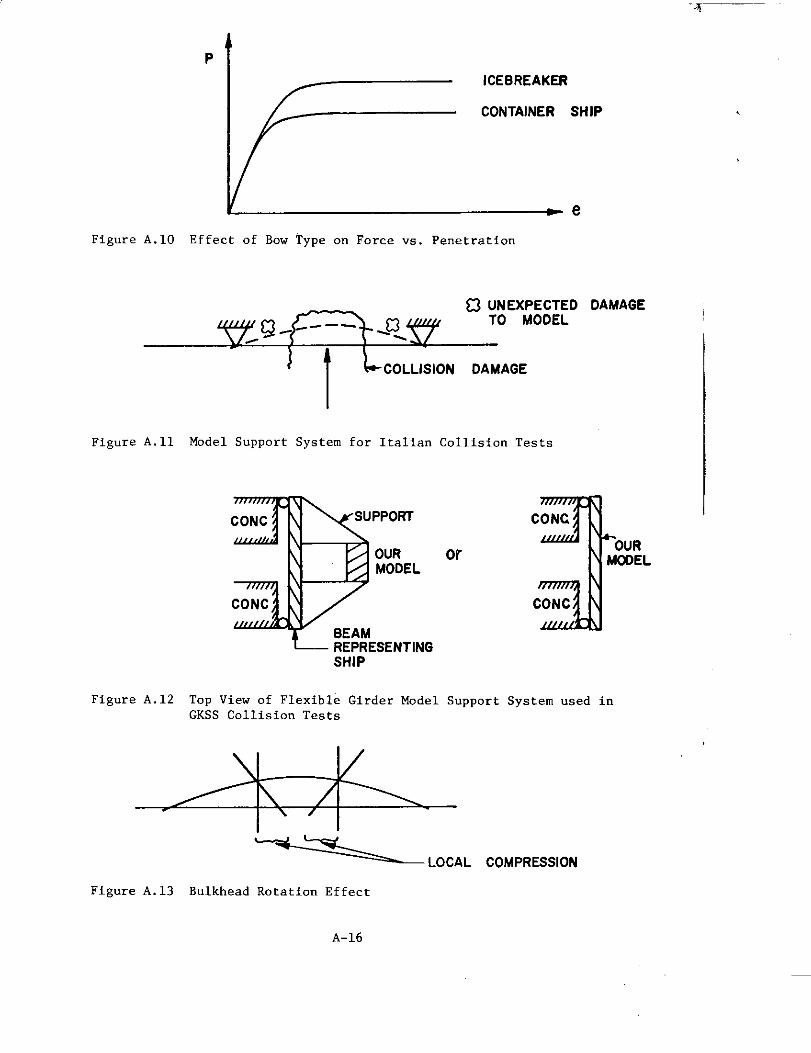
——.
P
I ~ ‘CEBREAKERc:Figure A.1O Effect of Bow Type on Force vs. Penetration
O ~;EX;lYVJD
‘l L-
COLLISION DAMAGE
Figure All Model Support System for Italian Collision Tests
3CONC suPPoRT
OURMOOEL
CONC
BEAMREPRESENTINGSHIP
Figwe A.12 Top View of Flexible Girder ModelGKSS Collision Tests
\ /
DAMAGE
3CONC
orOUR
M’OEL
CON’
Support System used in
—
~L~’~, ‘f)~,’’ss,oN
Figure A.13 Bulkhead Rotation Effect
A-16

~—-”--””
felt by the structure is a function of the barrier grillage response(and hence bow shape also) . Scale effects of this type have not beeninvestigated with the ESSO MALAYSIA because of facility limitations.
A.2.10 MEMBRANE TENSION AND SPECIAL SUPPORT SYSTEM
GKSS built a flexible girder on which to mount the models becauseexperience from previous Italian tests showed damage away from thearea of collision when the model was affixed to a solid foundation(shell and soldered frames separated) , as shown in Figure A.11.
To eliminate these problems, GKSS built an elastic girder on whichthey would mount their models . The girder simulates the responseproperties of the OTTO HAHN. It has not been changed for othertests due to its prohibitive cost but it is considered to be quiteadequate for all other ships tested.
The GKSS test facility sketched in Figure A.12 can provide boundaryconditions which can be accurately simulated by the finite-elementanalysis. An additional benefit arising from the flexible girder isthat the rotation of the bulkheads due to the impact load in the areaof the load is correctly simulated (local compression) , as shown inFigure A.13. Ignoring this phenomenon, as the Japanese did, leads tothe conclusion that increasing the thickness of the shell was betterfor ship protection, which is not correct for high energy collisions.It should be emphasized that the shell compression is only a localphenomenon, because depending on the impact location, an over-ridingship girder tension may exist in the area of impact .
Experimentation with this concept showed that the OTTO HAHN side shellabsorbed approximately 5% of the impact energy, which corresponds tothe value of the intercept in Minorsky ’s RT vs ET diagram.
A.2.11 MEfHOD OF ENERGY APPLICATION
Multiple impacts are presumably an acceptable way to apply the energy.Using two different experiments only a 2 to 3% difference in responsewas measured when 5 vs 2 impacts were used .
This method provides the opportunity for examination of the damage atdifferent stages. The assumption is that each impact has the oppor-tunity to destroy more bow structure. This was probably not the casewith some models that can be viewed at GKSS. Due to the short lengthof bow model, it was evident that the last one or two impacts (of atotal of five) were not realistic, since most of the structure hadalready collapsed and formed an almost solid body.
In calculating energy levels for the final energy of collision, onemust be sure to subtract the elastic energy which is associated with
each impact, since in the real case, only once does the structure seeelastic conditions. Woisin feels that accounting for the elastic
A-17

energy is not difficult.taken into consideration
~T..——
Strain hardening effects are automatically
accordinz to Woisin. since the materialfollows the stress-strain curve a;ter it goes plastic (see Figure A.14)
A. 2.12 AIRPLANE CRASH
The air crash problem was approached by using a Phantom jet plane anda stationary plant as a model. The impact is on the side of the ship(barrier) and the airplane is simulated as a solid projectile.
Dietrich has written a paper on the ,finite-element analysis of thephenomenon. Figures in the report show the impact force vs time dia-gram (imposed by the regulatory bodies) , the projectile penetrationlimits (calculated by formulas used by the German military forces) ,the assumed barrier geometry (where the outside shell is 38 mm thickand the inside longitudinal bulkhead is 20 mm thick) , and the result-ing deformations and stresses.
The finite-element analysis carried out on the system described abovewas done using tbe computer program SAP IV. This program was selectedover others such as NASTRAN and ASKA because of cost, documentationavailability and ease of use. Using quite high dynamic load factors(about 2) and an airplane approach velocity of 800 km/hr, the designwas found to be satisfactory. Most of the structure remained in theelastic range.
The available form of SAP IV does not contain plastic finite elementsand hence the modeling in the area of impact was poor. Further, com-patibility requirements among plate-stiffener elements were not satis-fied. This would require several computational attempts with varyingfinite-element mesh sites to establish the rate of convergence to thetrue solution.
A.2.13 ACCELERATIONS
Prof. Reckling has performed some calculations showing accelerationsof 1/2 g during impact (expected) and 4 or 5 g after break-up (if itoccurs) which is quite surprising. The reason for this is that afterbreak-up the CG shifts far from the location of impact and this createslarge lever arms which cause large accelerations (see Figure A.15).The acceleration time history is shown in Figure A. 16 and it corres-ponds to a 40,000 ton impact and a constant ship moment of inertia.The diagram should be read as follows :
“If the ship begins to break up t seconds after impact, then,of the accelerations observed (somewhere in the ship, at sometime after impact) the maximum will not exceed what is shownon the graph. ”
It may therefore be worthwhile to design a ship so that it breaks “pat a given time after collision, so as to minimize acceleration.
A-18

_..
u
kr-1
III
Q
(PARALLEL uNEs 5HOW THEELASTIC LOAO ANO UNLOADPROCESS BETWEEN IMPACTS )
Figure A.14 Stress-strain Relationships for Multiple Impacts
&i
a$=+flLI{L2(L
M=M, +M2a-4cr5g
Figure A.15 Center of Gravity Shifts in the Case of a Ship Broken
Up in Coliision
4 “
‘: : ~q
I -
0 I I I I 1 10 0.1 0.2 0.3 0.4 0.5 0.6
SECONOS
Figure A.16 Acceleration Time-History in the Case of a Ship Broken
Up in a Collision
A-19

_...
However, investigators feel that such a design would be quite diffi-cult at this stage.
A.2.14 RECKLING ‘S FORCE ANO ACCELERATION CALCULATIONS
The experimental force vs time diagram indicates that the force isalmost constant for a period of 2 seconds, with oscillations aboutthat constant value. Each peak probably corresponds to the beginning
of a bow buckle, since the number of peaks was equal to the number ofbow folds . See Figure A.17. The maximum computed value of force was90,000 MT, but the duration was extremely short.
Measured accelerations were converted to forces (added mass was assumedto be 1/2 of the ship mass) to compare with the computed forces. Theagreement was good, with the experiments always having values lessthan computed (conservative) . The computations were based on the upperand lower bound theorems. However, the static-moment distributionrequired for the lower bound theorem were difficult to obtain.
The method used to compute ultimate stresses is the one described byD. Faulkner in the Journal of Ship Research (March 1975). It is inter-esting to note that this method is the same as Cirard’s method of loadcalculation, but adapted to ship structures (Girard dealt with air frames).
Germanischer Lloyd’s has agreed to permit GKSS to use accelerationsfrom LNG ship codes for the NCS80. The values are about 1/2 g for wavemotion and 1/2 g for collision. These values are derived by previousexperience. It is interesting to note that the ships involved have nocollision barriers, but still the society permitted the use of accel-eration values related to them.
Reckling’s calculations were based on a beam of constant moment- of-inertia along the length, added mass of 50% of the ship mass, alsouniformly distributed. Impact force F is applied to the beam for aduration of t seconds and five response modes are computed.
As indicated, the computations are based on several severe assumptionand therefore the magnitude 3.65 g shown in Figure A.18 is far from afixed number. On the other hand, the general response shape is prob-
ably correct, in,the sense that a higher value of acceleration existsduring the first few milliseconds. Comparing the stress wave time toreach the reactor (about 0.01 see) to the higher acceleration duration(0.02 see) , it becomes evident that the reactor will feel that higheracceleration. Reckling and Woisin published results of this work andpresented it to the German Society of Naval Architects in November 1976.Genalis has re-analyzed the force magnitude on the barrier based onbow collapse. A detailed formulation is now available.
A-20
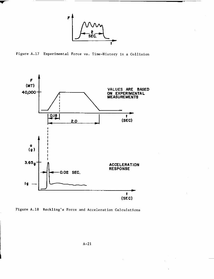
F
tn. SEC.
t
Figure A.17 Experimental Force vs. Time-History in a Collision
F t
(MT)
40’””- :-yD
ti(S:c)
1I
;IIII
I
(:)3.65g
IL
0.02 SEC.
Ig —
ACCELERATIONRESPONSE
(S:c)
I
\
i
Figure A.18 Reckling’s Force and Acceleration Calculations
A-21
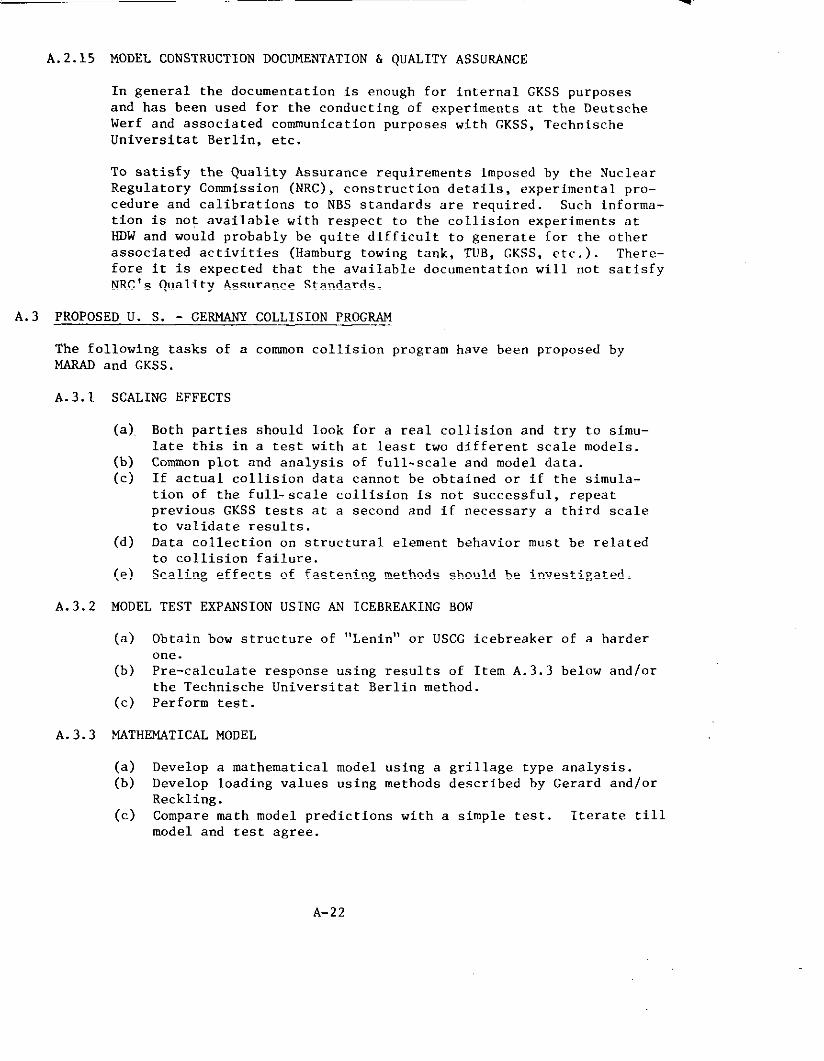
A.2.15 MODEL CONSTRUCTION DOCUMENTATION & QuALITY ASSURANCE
In general the documentation is enough for internal GKSS purposesand has been used for the conducting of experiments at the DeutscheWerf and associated communication purposes with GKSS, TechnischeUniversitat Berlin, etc.
To satisfy the Quality Assurance requirements imposed by the NuclearRegulatory Commission (NRc), construction details, experimental pro-cedure and calibrations to NBS standards are required. Such informa-tion is not available with respect to the collision experiments atHDW and would probably be quite difficult to generate for the otherassociated activities (Hamburg towing tank, TUB, GKSS, etc .). There-fore it is expected that the available documentation will “ot satisfy
NRC’s Quality Assurance Standards.
A.3 PROPOSED U. S. - GERMANY COLLI SION PROGRAM
The following tasks of aNARAD
A.3.1
A.3.2
A.3.3
and GKSS.
SCALING EFFECTS
(a). Both parties
late this in
common collision program have been proposed by
should look for a real collision and try to simu-a test with at least two different scale models.
(b) Common plot and analysis of full-scale and model data.(c) If actual collision data cannot be obtained or if the simula-
tion of the full-scale collision is not successful, repeatprevious GKSS tests at a second and if necessary a third scaleto validate results.
(d) Data collection o“ structural element behavior must be relatedto collision failure.
(e) Scaling effects of fastening methods should be investigated.
MODEL TEST EXPANSION USING AN ICEBREAKING BOW
(a) Obtain bow structure of “Lenin” or USCG icebreaker of a harder
one.(b) Pre-calculate response using results of Item A.3.3 below and/or
the Technische Universitat Berlin method.(c) Perform test.
MAT!U3NATICAL MODEL
(a) Develop a mathematical model using a grillage type analysis.(b) Develop loading values using methods described by Gerard and/or
Reckling.(c) Compare math model predictions with a simple test. Iterate till
model and test agree.
A-22

A.3.4 OBLIQUE IMPACT
(a) Perform feasibility study and design and costor floating model test facility.
(b) Analytic study ‘ofcollision barrier extensionand transverse directions.
(c) Development of tbe theory of impact mechanicscollisions.
A.3.5 INVESTIGATION ON ACCELERATION BEHAVIOR
study for a dry
in the longitudinal
in unsymmetrical
.
(a) Structural behavior’of ship after impact.(b) Reactor plant acceleration as a result of hull over-stress%ng.(c) Investigate methods of reducing acceleration in way of the
reactor plant.
A.3.6 MOTION BEHAVIOR OF VESSELS AFTER COLLISION
A.3.7 ADDED MASS & RADIUS OF GYRATION
Study added mass and radius of gyration atdifferent eccentricities, impact duration,
The following table summarizes the priorities and
high-velocity impact forwater depth, block coefficient.
responsibilities assignedto each task. Priorities were assigned on the basis of importance and ~rgencyto meet MarAd/GKSS schedules (A-highest; B-moderate; C-1owest). Parties inparenthesis are to play a supporting role to the designated lead party.
A.3.1
A.3.2
A.3.3
A.3.4
A.3.5
A.3.6
A.3.7
ITEMm(b)(c)(d)(e)
(a)(b)(c)
(a)(b)(c)
(a)(b)(c)
(a)(b)(c)
PRIORITYAAccB
AAA
AAA
BAc
BBc
c
c
RESPONSIBILITYBOTHGKSSGKSSu. s.u. s. (GKSS)
u. s.GKSS (US)GKSS
u. s.u. s. (GKSS)u. s. (GKSS)
u. s. (GKSS)GKSSGKSS (US)
u. s.u. s.BOTH
GKSS
u. s.
A-23

A.4 CURRENT STATUS AT GKSS
During the summer of 1977, Dr. Genalis visited CKSS to discuss the currentstatus and immediate future plans for further collision research. Thefollowing are his comments:
1. The discussion centered around the NCS80 project. Letnin stated thatthe overall project has stopped . As a general concept it has receivedappr”val from the reactor safety commlssi On (RSK). Since no nearfuture ship will be utilizing the developed plan there is no immediate
program to pursue this design further. However, as part of GKSS’S“base program” specific design pieces are being evaluated and approved,on paper, by the pertinent expert groups. For example, specific assump-tions used in the design of a specific safety system are being reviewedby the Deutsche Technische Uberwachungs Verein (TUB) for specific appro-val . Similar questions are being investigated with the Institute ofReactor Safety and with Cermanischer Lloyds.
GKSS is also spending some time i“ re-evaluating the economic pictureof the NCS80. Shipyard bids to the Inter-Atom and Bremer Vulcan arebeing refined based on information developed in the first-cut design.Subcontractors are also refining some of their bids. The result ofthis activity on NCS80 economics is expected to be an evaluation ofwhat economic conditions must be realized before the ship becomes aneconomic success.
In general it can be said that the NCS80 project manpower and budget
have been reduced, but under the GKSS “base program” work is continu-ing on specific items. The ship collision work is part of this baseprogram (not the specific NCS80 project) and it is therefore continuingas previously planned.
2. The 12th test in the series of model collisions has been finished. Thebow of the ESSO MALAYSIA caused no unexpected damage to the barrierdesigned for the NCS80. More qualitative information (similar to thator previous tests) was gathered. Even though considerable effort hadbeen expanded in instrumenting tbe model, quantitative measurementswere unsatisfactory and most sensors failed during the test. However,
the qualitative results were good enough to obtain the general approvalof the integrated safety enclosure concept for the NCS80.
3. In terms of considering tests with the icebreaker bow, GKSS has decidedto wait for the numerical results of the US mathematical model beforeadditional funds are expended, even thou8h their interest is high. One
instance which might convince them to deviate from this plan would be arequirement from the Canadians to perform such a test, assuming GKSSinvolvement in tbe Canadian icebreaker design.
4. In preparation for the discussion of the small, simple test designed toprove the validity of the Hydronautics numerical model, the discussionwas directed toward the current state of tbe GKSS test facilities.
A-24
Of three shipyards in the country around Hamburg, the oldest, DeutscheWerft, was chosen to be closed as the least profitable. This had forcedGKSS to consider moving its testing facility (originally located at thatshipyard) to the Geestacht grounds. In the process the facility wasto be improved and expanded. The yard did indeed close, a dam 6’ - 8’high was built (for unknown reasons) and a road was also temporarily
.
constructed to connect some old facilities with the waterf rent. TheGKSS facility ia located behind the dam (away from the waterfront) andnear the road. After negotiations GKSS found that the Hamburg Senatemight grant them a 99-year leaae on the land of the test site and there-fore all immediate plans to move the facility were abandoned. In itscurrent state the dam is a nuisance, but the road was a welcome addition.Final decisions have not been made.
Mr. Woisin’s general feeling is that carrying nut such tests at GKSS wouldbe impossible for several reasons discussed below:
Since the yard haa been closed there are no available support services,i.e. , electricity, stores, compressed air, water, etc. This situationcould be altered but not within a short time.
There are no cranes available to carry equipment and models over thedam, even though this could be a not-too-serious objection if the newroad is used.
The tests are carried out by the yard, not GKSS, and the yard does notexist anymore. Even if the group representing the yard were to act asa new form of yard management, they might not be interested in such asmall test.
GKSS has no experf ence in measuring model response. Eleven of theirtwelve tests involved only half-hearted attempts to measure carriagespeed, a few strains and total load at the supports. Since theirmeasurements during these 11 tests were so poor, they decided to reallypay attention to the instrumentation of the 12th test. The results of
the test were similar to all previous tests: Most instruments failed,what few readings were taken did not make any sense. Woisin mentioned
that all their reports of their experiments never show any measurementvalues. Based on this past performance Woisin felt that GKSS could
not guarantee any results from an effort to measure load, strain,acceleration or deflection.
A-25

APPENDIX B
STATUS OF THE DEVELOPMENT OF THE MATHIMiTICAL MODEL OF STRUCTURALRESPONSE OF ENERGY-RESISTING COLLISION BARRIERS AS OF DECEMBER 1977
.
In February 1976 Hydronautics Inc. submitted a proposal to MarAd for thedevelopment of a mathematical model of the structural response of energyresisting collision barriers, Extensive discussions between MarAd (C.Patterson) , G, G. Sharp (V, U. Minorsky, F. Genalis) and GKSS (H. Lettnin,G. Noisin, Dietrich) had previously formed the requirements for such atask, Dr. Genalis was asked to formulate a statement of work blending theprevious discussions in the Hydronautics proposal. This was accomplishedand Dr. P, Y. Chang proceeded with the modified contract.
The workscope called for six specific tasks, the sixth being left open forfurther negotiation. These items will now be discussed in turn and commentswill be made as to their status.
1. “Currently available, running, documented and generally acceptedsuccessful finite element programs will be evaluated to select oneto be used in subsequent steps. It is mandatory that the chosenprogram have the following attributes (in addition to those listed
above) :
a. elastoplastic dynamic. analysis capability
b. use of large number of degrees-of- freedom should be possible
c. pre-and post.processors of data should be available and docu-mented
d. the program should be available to both U.S. and Germananalysts, either commercially or through a government-to-government agreement, ”
Status: The following programs were considered: GPAD, EPIC 111, H326,OASIS , PIAST2 , SAAASIII , DYNS , HONDO, SAMSON, NESTS, EPSOLA, STRAW, BOPACE,CAP , ANSYS , ASKA, MARC, NEPSAP , NONSAP , ADINA. Of these, ANSYS, ASKA,MARC AND NONSAP are found to fit all the requirements. Further discussionswith GKSS (Lettnin, Dietrich) resulted in the final choice of ANSYS andNARC for concurrent invest igiations. Finally, ANSYS was chosen as the mosteconomical, (ReasOn for the other choices are available)
2. “A reasonable finite element mesh will be prepared, consiatant withthe power of the chosen element. The model will be of three-dimenaional geometry (i.e., including the egg-crate barrier, bulk-heads, decks, etc.), but the elements themselves will probably be
two-dimensional. Loading and boundary conditions will be consistentwith GKSS findings.
The geometry will be checked by graphically echoing the input datavia the input pre-processor (plotter) .“
B-1

Status: This task haa been completed. The geometry of the GKSS “egg-- barrier was simulated by plate and stiffener elements accounting fortwisting, bending and membrane actions of plates, stiffeners and flanges.
3. “Analyses will be carried out for two or three different meshes tOdetermine their adequacy. Consistency of results and use of thenext itsm will be used as a criterion of adequacy. ”
Status: This task has not been carried out, Therefore the convergenceof the finite-element grid as the number of degrees. of-freedom increaseshas not been investigated and there is no guarantee that an optimum costvs, accuracy trade off has been made, The result of the chosen mesh seemto predict the experimental results but it is not known if different resultswould have been predicted with a different (finer) mesh or if the sameaccuracy could have been achieved with fewer degrees of freedom which wouldbe cheaper.
4. “A simple test will be used to check the accuracy of the mathemat-
ical model. The test itself may be carried out by a differentorganization and is not part of this proposal. The results of thetest will be made available to check the results of the finiteelement analysis. ”
Status: Due to the schedule of this contract and due to the inability ofGKSS to perform such a simple test (temporary loss of their testing facility)
this task has not been accomplished.
5. “Upon satisfactory completion of item 4, the full mathematicalmodel will be used to simulate a collision test which has alreadybeen carried out by GKSS.
Since loading pressure time-history was not measured during the
tests, comparisons will be carried out using the best loadingestimates available and will be evaluated by the relationship ofthe measured and predicted structural responses. It should berecognized that lack of knowledge of the loads will require thatengineering judgment be used in case of reasonable disagreementof the responses. Presumably, since item 4 was successfullycompleted, gross disagreements will not occur. ”
Status: This task has been completed within the context of the above com-
ments. Boundary conditions simulated the GKSS experiments. Loads usedwere taken from very rough GKSS measurements. Meanwhile, Genalis prepareda detailed re-analysis and expansion of Reckling’ s load prediction method.Minorsky then used this method to predict loads in the collision of the OBOTARIl! (cylindrical, blunt bow) against the barrier. The results were within15% of the rough-measured values. An alternate method of load prediction
based on Girard’s approximations (NACA reports) is under investigation. Itis expected that when the load-prediction model is finalized the responsemodel will be re-run with a new set of loads.
B-2
6. ,,Th~ ~Odel WiI,I be ~ercised to Opti.IniZethe barrier. Fixedgeometric yariables Csuch as bulkheads, decks, etc. ) will not bevaried. However, stiffener spacing and modulus will be examined.Engineering valuea will be used (i,e,, only commercially available
stiffeners and plating will he considered, stiffener spacing willbe limited to sizea which permit fabrication, etc. ). Also, otherdesign constraints will not be violated (ylating will not be madethinner thsn required for hydrostatic heads, corrosion allowance,etc, )..”
Status: This task has not yet been completed nor is it contemplated.
B-3

APPRNoIX C
EXTENSION OF MINORSXY‘S ORIGINA,LWORK TO THELOW-ENERGY SHIP COLLISION REGION
As suggested by Norman Jones
C.1 APPLICATION OF MINORSKY‘S METHOD TO A FULL ENCASTERED BEAN
Minorsky has suggested, Ref. (Cl), that the energy absorbed in a collisioncan be related to a “resistance factor” thusly,
where‘T
= 414.5 ~ + 121900 (Ton-knot2) (1)
ET = energy absorbed in a collision (To”-knotz)
1$.= resistante factor or volume of materialinvolved in a collision (ftz - in)
Results from Table 1 of Ref. (C2) suggest that for minor collisions themembrane energy in stiffened hull plating and stiffened decks is import-ant, while other energies are less important.
By following Minorsky ’s general ideas but basing the energy absorptiono“ the equations for beams loaded transversely into the membrane range,
it was shown in the work of Ref. (c2) that the membrane energy of thedeck and hull plating could be estimated using beam theory.
As an example, consider a fully damped beam with a span “2L” which issubjected to a concentrated load P at the mid-span. Accordingly, for arigid perfectly plastic material with a yield stress Dy, and from equa-tion (23b) of Ref. (c3)
w = displacement under load
~ = ~ (uvt2B) = (aX,t2B)c L ‘4 ‘L
B = beam breadth
t = beam thickness
2L = beam length
rectangular cross-section
1...-...---1......1[‘~L~
If the assumption is made that me”brane behavior occurs at all displace-ments, the energy absorbed by the beam at displacement w is:
E=<w Pdw=<w2~c: d”= ~2t
u t2Bw2or,
_ avtBw2E ‘“yLt – ‘L
(2)
c-1

Keeping in mind that Minorsky defines ~ = volume2LBt
‘f ‘acerial = 144for the above bean, we now have,
~ - aVtBw2 R .144L ~ = ~ (;)’~’144
or, E = 72uy(~)2~
The units of the terms being:
~ = ftzin
y = lb/in2
w = in.
2L = in.
B,t = in.
But, Minorsky defines energy absorbed ET in tons-knots 2 units. Toachieve these units the following conversion is used:
E(lb/in) . ~ = ~ in (using long tons)
E— . 32.2 .2240
12 (tons)
remembering that 1 knot = 20.25 in/see
ET= ~~~~ 1 ~~~z,z ton knot’
_ 32.2 . 12‘T - 2240 . (20.25)’
. 72 Uy (:)2 ~ (Ton knotz)
‘T= 0.030288 Uy (;)’%
For steel, Oy = 30,000 lb/in2 , then
‘T= 908.64 (:)’% (Ton knot’)
(3)
(4)
(5)
C. 2 INFLUENCE OF MATERIAL STRAIN RARDENING
If au is the ultimate stress and u the yield stress, then an estimateof the importance of strain harden~ng could be made using the averagestress:
~a=~ (6)
in the equations (2) to (4).
c-2

C. 3 COMPARISON WTTH EXPERIMENTS OF REFERENCE (C2)
It can be shown that the load-deflection (P - w) relation used in this
discussion with CTagiven by equation (6) is identical to equation (10) .
of Ref. (C2) when the load is at the mid-span. Thus the equations usedto calculate the plastic energy in the last column of Table 3 in Ref. (C2)must be the same as equation (2) when using equation (6). It is evidentfrom this table that quite good predictions are found for bnth flat andstiffened plates loaded at mid-span. This then forms the experimentalbasis for equations (4) - (6).
C.4 N.C.R.E. FORMLILA—
From Ref. (C4), the energy absorbed in deck plating is
E = 0.9 i?yT {tan(ct/2)+ .25 pz)
where T is total thickness of decks
a is included angle of bnw
p is depth of penetration
According to Minorsky ’s definition,
(7)
1{’
a
Deck
‘1Thickness, T .__. ___
‘T = (+) (%) 2 P tan (u/L) (ft’-in)
therefore
E =0.9~ (tan (a/2) + 0.25} ~4~a~’T(a,2)
or E = 64.8 Uy (1 +ta”0~;?2) } ‘T
(lb/in) (8)
To change to ton-knotz , the previous unit conversion is used again
= 64.8UY {1 +0.25 32.2 . 12
‘T tan (a/2)} ‘T x >240 . (20.25)’
or ET = 0.02726uY {1 +ta:’::/2)} ‘T
(ton-knotz) (9)
Again for steel,
uy = 30,000 lb/in2, and
‘T = 817”78 ‘1 + ta~”~~/2)) b(ton-knot’) (lo)
Two tables are shown below. the first of which. for three values of the“resistance factor”, R , compares Minor sky ’s equation of absorbed energy,equation (1), with theTNCRE equation ofa. The yield stress Uy, is for steel.
E with two values of wedge angle,T;e second table, again for CJyof
c-3

.- -
C.5
.5
steel, gives values of ET, equation (5),under load per length to the “resistance
relating the average displacementfactor”.
CALCULATIONS
NCRE Eauation (10)RT
(ft’in)
1000
2000
3000
MinorskyEquation (1)
ET (ton ktz)
536400
950900
1365400
7%
(ft’in) w/2L = ~
500 18173
1500 54518
3000 109037
CONCLUSIONS
Y = 36,~ . 300
ET (ton ktz)
1580779
3161558
4742337
) lb;iiza = 60°
ET (ton ktz)
11711884
2343778
3515667
Equation (5) Uy = 30,000 lb/inz
w/2L = ~
72691
218074
436147
201920 I 290765
605760 I 872294
1211520 1744589
wf2L = ~
454320
1362960
2725920
Jones discussion in Ref. (C2) remarks that a plate ruptures when40” < w < 50”, approximately, if 2L = 150” (span), B = 30” (breadth),t = 1.”(thickness),
1>.2L ~“
Noting this, equation (5) with ~ = ~ is essentially parallel to Minorsky ’sequation (1).
Also note that eq(,ation (5) with ~ = ~ is almost parallel to t~.eNCREformula with a = 60°.
For a given value of required ener~y absorption one could evaluate differ-
ent designs (i.e., values of ~) from Figure (Cl),This could also be done for designs which lie outside the shaded region.Perhaps only designs which lie to the left hand side of Minorsky ’s equa-tion (1) could be considered acceptable.
C-4

Therefore, from the above, it can be seen that for minor collisions, it
is necessary to specify w/2L which could be regarded as the average valueof the maximum permanent displacements of the deck and side plating of a
ship .
The influence of material strain hardening has not been considered in thefollowing Figure (Cl). However, ea,”ation (5) could be modified by using
equation (6).
If a material has a yield stress u and an ultimate stress (lU,then theresults predicted by equation (5) ~n Figure (Cl) should be multiplied by
(*U-.;o;~) .v
c-5

0 J&. ~“
.
a+
40W
2L
L,10
3500 —
1000
WJ -—~—/—
00 300,000 Wc@oo 900,000 *00,000 I@opoo I,eoo,ooo q
ET (TON -KNOT2)
FigureC-1 Resistanceto Penetrationvs EnergyAbsorbedin Collision

C.6 VAN MATER’ S EXTENSION TO JONES ‘ SUGGESTED PROCEDURE
Consider the effect of a concentrated load at variable location on afully encastered beam.
From Haythornwaite, Ref. (C5), using Jones’ notation:
P=2 Ma (2L)
c ab
Substitution gives
Pc
‘t’ (+ + +)‘“y T
2
Mo= am,y4
P _ ‘2W(: : 1)
it-t’
For a = b = 1 this reduces to JO”eS’ ~xpres~io”.
For the load at variable location,
P= =P.L1~(:+;)
C%
Since E=PY2Ct
then to obtain thelocation we simply
.05
.10
.20
.30
.40
.50
(11)
(12)
(Jones)
energy absorbed by the beam under a load at variablemultiply the center load energy by B.
‘(a,b) = ‘~ “ 6(13)
&2L
.95
.90
.80
.70
.60
.50
6
5.262.781.561.191.041.00
greater energy is absorbed by theas the load moves off the center
Thus for a given displacement and spanbeam for off center loads. Of course,then the strain in the short leg will be proportionately greater andrupture will occur at smaller w.
c-7

Next, we will use McDermott,
McDermott gives two criterianotation the first criterion
Ref. (c6), to approximate a limiting w.
for failure of a stiffened beam. In ouris:
w-~(a Ea+bcb)+d2bc (14)
where cCb
= strain in legs a,ba’
6bc
= maximum value of deflection during bending phase.
From inspection of Table VII of Ref. (c6) take
dbc
= .15W
For an approximate treatment to determine the relationship between Eaand c
bwe will consider geometric comparability only. For a more rigorous
treatment static compatabilit must also be considered . Assume leg a isthe short leg.
a—bl
‘v
*Xw ~ v~~*P$ v
az(ca+l)z -a’= w’=bz(cb+ l)’ -b’
which leads to,
c: + 2Cb
= (c: + ‘2Ea} (:)’
For ABS steels rupture will occur when ac = .10 is reached. Since the strain inthat in leg b,
c = .10, E2 = .01a a
< Ea, E2‘b b
= negligible.
Then,‘b
= + {.01 + 2 x .011 (;)2
or approximately
limiting value of strain,leg a will be greater than
Cb =+ (:)*
1E=—a 10
C-8

Substituting in (12) gives
l?’ =*(.+$2
.98w2 = .20 a’
w = .452 a
This result contains manytendency toward linearitythis result we may also infer that, at rupture,
) + (.15 W)2
(15)
oversimplifications but still suggests a strongin tbe limiting displacement at rupture. From
$= .452 (;) = .452 (.5) = .226
Rewriting (2),
E =0 o 4LBt .Ey
(>) 2
2L
and incorporating (13)
‘(a, b))z . ~‘(a,b) = ‘y ‘ 4LBt “ ( 2L
~w(a,b)),‘(a,b) _ 2L— _ “B
‘f (*) 2
‘~ .452%, ~- .452(.5), and 6 ‘~ (aNow ,2L J) (+)
/2L t2L
After substitution (16) reduces to
(16)
(17)
Again, this result contains many oversimplifications but it shows clearlythat a stiffened panel between bulkheads will absorb much Iess energybefore rupture as tbe strike point moves away from the center span.
Finally, let us plot the McDermott data on a Minorsky plot. McDermotttested two section shapes, a flat plate and a flat plate stiffened by aninverted angle.
c-9

b=6in b = 6.00 inArea = 1.188 inz Area = 1.471 inz
~ = 1.188—= .198 in t
1.4716.00
=—= .245 inav 6.00
We will adopt a variation on Jones’ definition of R :T
where
TESTNO.
12345689
10
RT=wx2Lxt
~ = displacement at rupture
2L = distance between supports= 30 in for McDermott tests
ET = area under load-displacement curve. Conversion factorfollowing Jones: ton-knotz = .4206 x kip-in.
LOADSECTION LOCATION w
‘TET
a/2L
flat plate .5 9.70” .400 164stiffened plate .5 10.23 .522 230*stiffened plate .5 4.47 .228 40stiffened plate .4 7.73 .395 151flat plate .5 4.81 .200 33stiffened plate .5 8.11 .414 145stiffened plate .167 3.69 .188 54stiffened plate .2 6.32 .323 8(3*
flat plate .10 1.88 .078 18
*ET based on equation (10) of Ref. (C6). See Table 3 of Ref. (C6).
Results are plotted in Fi8ure C2 together with lines from the Jone~form la.
‘1Note that the slope of the data band falls between ~ = >
and —.A
C.7 DISCUSSION
The approach taken by both Jones and Van Mater is certainly an oversim-plification of circumstances that would prevail in an actual collision.Still the results suggest that there is hope for tbe development of a
simple Minorsky-type relation which would permit the prediction of thedepth of incursion at shell rupture for a given input in collisionKinetic energy within reasonable upper bound error. The analyses usedby Jones and Van Mater are intended simply to demonstrate feasibilityof the approach, but there is a vast margin for refinement and improvement.
c-lo

Iw.
71-
/
/“/
/( /
$$9.
‘\\
9
1/
“–n’
/
//
/
ET
WH
ET D TON - KNOT2
T~,2 ‘
>
//
/
W,L IN FEETT IN INCHES
ET =AREA UNDEREXPERIMENTAL —CURVE
Iw OF McDERMOTT OATA WITH MB@_
FORMULA*
).030288 u (f)z RT
Wv+uuE m=
x) 250 :
Psi —
Figure C?. Comparison of McDermott Data with Jones’ Formula

TO refine the method will require a substantially greater body ofexperimental information including further tests of the McDermott typeon a wider variety of section shapes, load locations, etc. Some tests
cl.C2.
C3.
C4 .
C5.
C6.
should include simplified ship sidetests should be dynamic to test the
REFERENCES
shell and bow structures, and somevalidity of the quasi-static approach.
Minorsky, V. , Journal of Ship Research, 1959, pp. 1-4.
McDermott, Kline, Jones, Manias, Chiang, SNAME Transactions, 1974,DD. 382-414.~~nes, N. , International Journal of Mechanics and Science, 1973,Vol. 15, pp. 547-561.Jones, N. , Nuclear Engineering Design, 1976, Vol. 38.
Haythornthwaite, R. M. , “Beams with Full End Fixity, ” Engineering,
January 25, 1957, pp 110 - 112.McDermott, J. F., et al, “Tanker Structural Analysis for Minor Colli-sions,” Trans. SNAME, 1974, Vol 82.
C-12

APPENDIX D
CRITICAL RIVIEW AND ASSESSMENT BY PROFESSOR NORMAN JONESOF THE ASSUMPTIONS IN THE ROSENBIATT METHOD
D.1 BACKGROUND
In order to obtain a separate, independent assessment of the variousassumptions made in the Rosenblatt method, Professor Jones of M.I.T.was asked to review and comment on these assumptions. A summary ofhis contribution is presented here. All page and figure numbers
referred to by Professor Jones correspond to the report entitled“Tanker Structural Analysis for Minor Collisions, ” which is listed asreference (2) in the main bodv of this volume or to ADDendix C of this. . . .volume which presents a proposed extension of Minorsky ’s work.
D .2 RSVIEW AND ASSESSMENT OF THE M. ROSENBLATT MSTHOD ASSUMPTIONS
The general procedure developed in the report is a sensible onethink a valid anDroach to the oroblem of minor shiD collisions.
and IIt. .
does have various limitations, as we have discussed and as remarkedbelow, and one may quibble over some of the details. However, 1 believethat it is a useful framework which could be built upon and computerized.Incidentally, minor collisions are defined as those which cause extensivedenting and plastic deformations which do not cause rupture. However,the collisions must be sufficiently severe to ensure that elastic effectsare negligible.
(1) An important restriction in the Rosenblatt method is the factthat it does not account for the possibility of fracture of the platingprior to the attainment of the ductility limit.
In this regard, it might be noted that Akita, Ando et al. (Nut.Eng. Des. ~, 365-401, 1972) identified two types of fracture inidealised side structures impacted by rigid bows. Deformation typeoccurs when the strain (c) directly below the loading point is lessthan Cb, while crack type behavior occurs when c > Cb. The quantityCb is an experimental constant and the model tests suggest cb = 0.3.This value of strain is similar to the engineering fracture strain ofmild steel so that the crack-type behavior occurs at the ductilitylimit of the material and is therefore not related to unstable crackpropagation, which would be predicted by a fracture mechanics study.
The Rosenblatt method also includes a ductility limit but no considera-tion is given to unstable crack propagation. Unfortunately, it wouldnot be a simple task to include this feature in the Rosenblatt method(or any method for that matter) since the influence of material
plasticity must be considered. No simple procedures for predicting
D-1

the unstable crack propagation of elastic-plastic bodies are currentlyavailable, and time-consuming and expeneive numerical schemes must beused. Actually, this area is one in which many questions remainunanswered and a number of studies are currently probing variousfeaturea of the phenomenon.
A very simple procedure for predicting the failure of ductilebeams loaded dynamically was presented in Trans. A.S.M.E. , J. Eng. Ind. ,Vol. 98B, 131-136, 1976. This theoretical method examined tensiletearing of beams and ahear failure and surprisingly good agreement wasobtained with some experimental tests. These general ideas do not,however, involve fracture mechanics, nor have they been ueed toexamine static problems.
Even though it would be difficult to consider fracture mechanics ,it would, nevertheless, be very worthwhile to attempt to refine theexpressions for the strains at the hard points so that rupture mightbe more accurately predicted at these locations. (See p. 5-3 for someremarks on this important point. )
(2) The Rosenblatt method assumes that a striking bow is rigidso that any plastic energy which may be abeorbed in a bow~s dis-regarded. Also ignored is any destructive capability that astriking bow may posseas.
The plaatic-energy absorption of a bow could be estimated by con-sidering the behavior of the individual members. However, unless somedrastic simplifications were to be made (e.g., those of Minorsky or anN.C .R.E. type procedure) , then the amount of analysis would probablybe comparable to that already undertaken in the Rosenblatt report fora struck ship. The destructive capacity of a bow on the side shell ofa struck ship would be much more difficult to predict. Another diffi-culty would be partitioning the total energy absorbed in a shipcollision between a struck ship and the bow of a striking ship. However,this latter difficulty could probably be overcome by estimating themagnitude of the total force responsible for damage to the etruck shipand equating it to the resultant total force acting on a striking bow.It is then conceivable that the areas of damage on struck and strikingships will not match so that some iterative scheme might be required.
In order to remain consistent with the struck-ship analysis in theRosenblatt report, the proposed bow analyais should also be quasistaticand not dynamic.
(3) The proposed extension of Minorsky ’s method for minor shipcollisions (see Appendix C of this volume) is a simple procedure whichmight be useful for estimating the behavior of ships involved in minorcollisions. It contains a development of the basic relationship
D-2

(equation (5)) which is compared on a RT v. ET plot with the Minorskyand N.C.R.E. formulae.
In Appendix C, it is remarked that a test specimen examined byMcDermott et al. (Trans. S.N.A.M.E. (1974)) ruptured when ti/2L = 1/3.
(W = maximum displacement, 2L = span.) It is Interesting to note fromthe RT vs ET plot that the theoretical predictions of equation (5) withW/2L = 1/3 are similar to Minorsky ’s empirical relation (equation (1)).Thus , equation (5) with W/ZL = 1/3, or Minorsky ’s equation (1), may be
considered to provide an upper bound on the energy absorbed (ET) for agiven resistance factor RT (volume of material participating in acollision) . Thus, equation (5) with W2L < 1/3 provides an estimate ofminor damage which is manifested as dented plating and bent decks on thestruck ship. Incidentally, minor collisions are not necessarily re-stricted to the shaded region in the RT vs ET plot. It would appearthat collisions related to a larger value of RT could also be classedas minor provided ET is less than the corresponding values predicted byMinorsky or equation (5) with W/2L C 1/3.
The method is obviously tentative but I feel that it might proveuseful for ranking and comparing minor collisions, just as Minorsky ’shas been for major collisions.
It might be interesting to estimate the values of RT for the sixcollision cases examined in the Rosenblatt report on page 4-1 and plotthe results on the RT vs ET plot. Hopefully, they would lie to the
left hand side of Minorsky ’s formula and near equatiOn (5), withW12L = 1/3.
(4) Assumption 11 on page 3-9 of the Rosenblatt report is animportant one which does not appear to have sufficient support. Itis assumed that plastic strains equal to one-half the strains at theends of the damaged length occur in the stiffened hull within the webframe space just beyond the damaged length. Now the plastic energydue to membrane strains in the stiffened hull dominates the energybalance as shown in the table of page 4-9. Thus, this assumptionpresumably is responsible for a significant membrane energy absorption,particularly when only one or two web frame spaces are involved in acollision.
I assume that assumption 11 is based on the observation made onpage 6-21, which in turn is based on the experiments conducted usingthe test rig illustrated on page 6.3. It is not clear whether thisarrangement faithfully reproduces the behavior of a plate in a ship.There are some doubts in my mind concerning the flexibility of thesystem. Are there any other independent tests to support assumptionI1? Ho” ~“~h would the theoretical predictions change if the plaStiC
energies in the end spans were ignored?
D-3

(5) Equation (3-5) on page 3-20 of the Rosenblatt report is usedin a number of places in the theoretical analysis (e.g. , pp. 3-25, 3-26and 3-27) . This relation is developed for small rotations and displace-ments. In fact, this assumption might not be satisfied even for someminor collisions, since W/2L can reach 1/3, as remarked in (3) here.It appears unnecessary to make this approximation and either the exactrelation could be used or an additional term retained in the seriesexpansion. The same remarks also apply to the equilibrium equation (3-6)on page 3-29.
(6) How sensitive is thereport to the factor 1.5 on p.limit on the value of F,m giventensile test ductility?
theoretical analysis in the Rosenblatt6-28 which is used to provide an upperby equation (6-4) (on page 6-25) to the
(7) The types of collisions which might be studied using theRosenblatt method are restricted , as discussed in item 5 on page 3-3.In order to broaden this class of collisions, any plastic. energyabsorption in the bottom of a struck ship, in the transverse bulkheadsor in the bilge strake, could be estimated by considering the plaaticbehavior of these individual components due to the imprint of a strikingbow. It is remarked on page 5-4 that, in certain collisions, the strainsin the bilge area are primarily longitudinal membrane strains. Thisleads to the possibility of important energy absorption in the bilgearea.
(8) A number of assumptions have been made in the development ofequations (2-1) to (2-7) which are not stated in the report:
(a) The tangent modulus (Et) on page 2-14 is assumed to beconstant.
(b) Mp/Mo = Uy/UU on page 2-15 does not appear to bestrictly correct. For a rectangular cross-section,for example,
M2
p. _QYL___~ 2
{
(U”- u)t,
4 ~+2 3 }
when assuming linear strain hardening (i.e., Et constantas in (a) above) and using simple moment- equilibriumconsiderations. Thus Mp/Mo = 3uy/ {oy + 2UU} which
D-4

approaches the value in the report only when
~Y = au (i.e., Et > O). What is the value ofMp/Mo for other cross-sections? It appears
unnecessary to make this approximation sincethe analysis would not be any more difficultusing the correct value of the ratio.
(c) There are many other assumptions peppered through-out pages 2-14 to 2-16 and they need to be con-stantly reviewed in the light of new experimentalresults as they become available.
(9) I have only had enough time to concentrate my attention onthe right-angle collision case and I have not studied the details ofthe oblique collision case in the Rosenblat t report. It appears thatthe energy expressions developed for a traveling yielded zone on p.2-16 are only used in the analysis of oblique collisions. Merely
multiplying the expression on the top of page 2-17 by 2.0 to accountfor the plastic energy consumed in straightening appears to be acrude approximateion. The Bauschinger effect is ignored, despite thefact that it may be important for the large strains involved in shipcollisions. What about the influence of residual stresses? After
all, it is impossible to achieve an unloaded state (zero moment) whenthe bar is unloaded to a zero curvature (straight) . It would, there-fore, appear worthwhile to examine the validity, or otherwise, of thefactor 2.0 used on page 2.17.
Finally, I do believe, as I said at the outset, that the theoreti-
cal method developed in the Rosenblatt report provides a useful frame-work for the future study of minor ship collisions. Equation (5) inthe accompanying report might or might not be useful as a crude aid inthe preliminary design of protective structures involved in hypotheticalminor collisions. It might also prove useful for ranking the collisionprotective capability and margin of survivability of different ships.
\
D-5

SHIP RESEARCH COMMITTEEMaritime Transport ation Research Board
National Academy of Science$-National Research Council
The Shipinteragency Ship
********
Research Committee has technical cognizance of theStructure Committee’s research program:
Mr. O. H.Mr. M. D.
Dr. J. N.Mr.. D. P.Mr. W. J.Mr. A, C.Dr. W. R.
Oakley, Chairman, Consultant, McLean, VABurkhart, NavaZ Oceanography- Division, D@artment of the Nc;y,
Wcehington, D. C.Cordea, Sen-ior Staff Met-d lurgiet, ARMCOINC., Middletoun, ORCourt sal , Vice Besident, DRAVOCorporation, Pittsburgh, P.4Lane, Consultant, Baltimore, MDMcC1 ure, AZan C. McCZure Associates, Inc., Houston, TXPorter, Vice ties. for Acadetic Affaire, State Univ. o? k’. ~.---
Karitime Coilege
Prof. S. T. Ro1fe, Civil Engineering Dept., University of XansasMr. R. W. Rumke, Executive Secretary, SIip Research Committee
********
The Ship Design, Response, and Load Criteria Advisory Groupprepared the project prospectus, evaluated the proposals for this project,provided the 1iaison technical guidance, and reviewed the project reportswith the investigator:
Mr. W, J. Lane, Chairman, Consultant, BaZtimore, ~Prof. A. H.-S. Ang, Dept. of CiviZ Engineering, University of IllinoisProf. S. H. Crandall, Dept. of Mech. mgrg., Massachusetts Imt. of TechnologyMr. L. R. Glosten, L. R. GZosten Associates, Inc., Seattle, VAMr. P. M. Ki mon, EXXONInternational Company, N. J.Dr. O. H. Oakley, Jr., -eject Engineer, GULF R&D Company, iiouston, TXProf. R. H. Scan 1an, Dept. of CiviZ & GeoZogicaZ Engrg., Princeton UniversityProf. H. E. Sheets, Chairman, Dept. of Ocean Sngrg., Univ. of Rhode IsZmdMr. J. E. Steele, NavaZ Archi$ect, Quakertom, PA
********

SHIP STRUCTURE COMMITTEE PUBLICATIONS
Thesedocumentsare distributed by the National TechnicalInformation Service, Spring field, Va. 22151. These doc -wnentshave been announcedin the ClearinghousejournalU. S. GovernmentResearch& DevelopmentReports (VSGRDR)t.nderthe indicatedAD nwnbeys.
SSC-272, In-Service?e~fomunce of St.wctiwczlDeiailkby C. R. Jordan andC. S. Cochran. 1978. AD-A057212.
SSC-273, Survey of structuralTolermces in the u.s. C0~Qrcia:9~-EhzildingIndustryby N. S. 8asar and R. F. Stanley. . AD-AD57597.
SSC-274, DeveZopment of an InstrwnentictionPackage to ,?ecordFuZZ-ScaleShip SlamData by E. G. U. Band and A. J. Euler. 1978. AD-A059549.
SSC-275, The E??ect of Strain .k’de on -the Toughness C.r Ship Steels,’by p. H. Francjs.T. S. Cook, and A. Nagy. 1978. AO-A059453.
SSC-276, FractureBelzzviorcharccterizzt<o~o.?ship Steelsand WeldmentsbyP. H. Francis, T. S. Cook, and A. Nagy. 1978. AO-A058939.
SSC-277, OriginalRa&.rand StanCardTw%r Jlcoewte?SL-7 Con?ci.ershigZc:a.?eductionand CoPPeLztionSc.~le by J. F. Dalzel 1. 1978. AD-A062394 .
SSC-278,
SSC-279.
SSC-280,
SSC-281 ,
SSC-282 ,
SSC-283 ,
SSC-284 ,
SSC-285 ,
SSC-286,
Wavemete?Data ReductionMetFociand In-:ticl3atc for the SL-7Contai?zershipby J. F. Dalzel1. 1978. AD-A062391.
wdi fied ,?adczrand StandardFw?er h)avemete? SE-7 Con%oinersh+ k-hby J. F. Oalzell 1978. AD-A062393.
Resultsand Soalucztionof the SL-7 Contcinership.?atir-Wd Ftie?e?Wcve-meter Data by J. F. Dalzell 1978, AD-A062392.
Bibliogmphy fo? the .%ti-yof %ope 1ler-indxzedVibrationiz Bd?1StructuralEzementsby O. H. 8urnside and D. O. Kana. 1978. AD-A062996.
Comparison of StressesCa7-culctedUsingthe DAISYSystem to ThoseMeasuredon the SL-7 Containershiptiogroxby H. Y. Jan, K. T. Chang, andM. E. Wajnarowski. 1979.
:,L:~tur: ~;~ey on the CclZision and Growding Projectiono.fSkips by
Llitical Evaluationof Lou-EnergySkip CoLzision-hnngeTheoriesadDesignMethobzogies - VolumeI - Svakztion and ReconnnendationsbyP. R. Van Mater, Jr. , and J. G. Giannotti 1979.
Critiea2~a2ucztionof Low-Energy%Ip CoZ.Zision-D@nageTheorieszvdDesignMethodclogies- VolumeIi - LiteratureSecrchand Revieu byP. R. Van Mater, Jr., and J. G. Giannotti. 1979.
Resultsof the First Five “DataYears”of EztremeStressScratchGcugeData Co22ectionAboardSea-Land’ssL-7’s by R. A. Fain and E. T. Booth.1979.