cross resonant optical antenna -...
TRANSCRIPT
Cross Resonant Optical Antenna
P. Biagioni,1,* J. S. Huang,1 L. Duo,2 M. Finazzi,2 and B. Hecht1,†
1Nano-Optics and Biophotonics group, Department of Experimental Physics 5, Wilhelm-Conrad-Rontgen-Center for ComplexMaterial Systems (RCCM), Physics Institute, University of Wurzburg, Am Hubland, 97074 Wurzburg, Germany2LNESS—Dipartimento di Fisica, Politecnico di Milano, Piazza Leonardo da Vinci 32, 20133 Milano, Italy
(Received 19 December 2008; revised manuscript received 5 March 2009; published 22 June 2009)
We propose a novel cross resonant optical antenna consisting of two perpendicular nanosized gold
dipole antennas with a common feed gap. We demonstrate that the cross antenna is able to convert
propagating fields of any polarization state into correspondingly polarized, localized, and enhanced fields
and vice versa. The cross antenna structure therefore opens the road towards the control of light-matter
interactions based on polarized light as well as the analysis of polarized fields on the nanometer scale.
DOI: 10.1103/PhysRevLett.102.256801 PACS numbers: 73.20.Mf, 68.37.Uv, 78.67.�n, 84.40.Ba
Polarized photons represent a fundamental probe tostudy the behavior of electrons in matter at optical fre-quencies, since they induce transitions that can be analyzedin terms of selection rules based on parity and angularmomentum conservation. Optical fields with a well-defined polarization state are therefore of primary impor-tance in many spectroscopic and microscopy applications[1]. For example, optical techniques widely used in solidstate physics, like ellipsometry [1] or magneto-opticalFaraday and Kerr effects [2], require the use of polarizedlaser beams, and sources of polarized single photons rep-resent one of the building blocks of many quantum infor-mation processing concepts [3]. Nonlinear optical effects,such as second-harmonic generation, are also stronglypolarization dependent [4,5]. The envisaged scaling downof all such applications to subdiffraction interaction vol-umes, as required by the ever-growing interest in nano-structured materials, will rely upon the availability of effi-cient sources of localized and enhanced polarized fields.
In this context, subwavelength apertures at the apex ofmetal-coated tapered fibers so far have been among themost used probes in scanning near-field optical microscopy(SNOM). However, fiber-based aperture probes sufferfrom very low throughput and strain-induced birefringenceeffects which can be detrimental for polarization-contrasttechniques. Despite such drawbacks, SNOM setups withpolarization control and analysis have been successfullyimplemented, and their application has been demonstratedfor, e.g., magneto-optical imaging of magnetic films [6–8],polarimetry [9], linear dichroism mapping [10,11], fluores-cence circular dichroism for spintronic applications [12],or single-emitter polarization mapping and control [13].The use of hollow-pyramid SNOM probes has also beenproposed in this context [14,15].
Over the last decade, noble metal nanostructures havebecome key elements for the engineering of enhanced andconfined fields, as they combine geometrical effects (e.g.,lightning-rod effects) with localized plasmon resonances,giving rise to large local intensity enhancement factors.The nanometer-scale modal volumes of such fields are
ideally suited to promote the coupling to nanometer-scaleemitters, like single molecules or quantum dots, leading toenhanced fluorescence [16,17] and spectroscopy [18]. Ofparticular relevance in this context are resonant opticalantennas [19–26], since they potentially exhibit very stronglocalized fields in their feed gap, with local intensitiesenhanced by factors up to several thousand with respectto the incoming field. So far, mainly linear antennas (C2v
symmetry) have been proposed, either in the form of dipoleantennas [19,24,25], bow-tie antennas [20,21], or mono-pole antennas [23]. However, the C2v symmetry of linearantennas allows only one field component along the an-tenna axis to be present in the feed gap. Coupling tonanomatter is therefore restricted to transitions with dipolemoment projections oriented along the antenna axis.Indeed, it has been recently shown experimentally that,for a single-molecule interacting with a linear opticalantenna, the emitted polarization coincides with the an-tenna main axis rather than with the direction of the emittertransition dipole [27].Moreover, a C2v symmetry rules out experiments in-
volving circularly polarized excitation and emission,which are a requirement for many envisaged applicationssuch as the study of the response of chiral molecules [28],the study of spin dynamics and circularly polarized lumi-nescence in semiconductor materials and devices for spin-tronic applications [12], as well as the scaling down tosubdiffraction resolution of recent breakthroughs in opto-magnetic bit encoding via the inverse Faraday effect [29],which would allow ultrafast all-optical writing ofnanometer-sized magnetic information.In this Letter we propose a novel optical antenna con-
figuration with fourfold (C4v) symmetry, a cross antennastructure, consisting of two perpendicular dipole antennaswith a common feed gap. We show by simulations that across antenna is able to confine and resonantly enhancepolarized optical fields with high fidelity. Moreover, wedemonstrate that the same structure can efficiently radiatepolarized waves generated by a single dipole emitter, in-creasing its emission rate without perturbing its polariza-
PRL 102, 256801 (2009) P HY S I CA L R EV I EW LE T T E R Sweek ending26 JUNE 2009
0031-9007=09=102(25)=256801(4) 256801-1 � 2009 The American Physical Society
tion pattern. From an experimental point of view, a reso-nant cross antenna may be structured on top of a flattenedatomic-force microscopy tip [30] in order to scan it over asample of interest. It should be pointed out that, in view ofsuch applications, intensity distributions right outside thefeed gap are a realistic description of the actual averageintensity experienced by the sample.
The proposed concept rests upon the very basic knowl-edge that any arbitrary polarization state carried by a trans-verse propagating electromagnetic wave can be decom-posed into two linear components, each one with the appro-priate amplitude and phase. In this frame, two perpendicu-lar linear antennas, with a common feed gap, are in prin-ciple able to sustain two such linear components, which arecoherently added in the small volume of the feed gap.
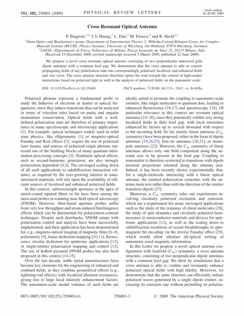
A sketch of the here proposed antenna structure is shownin Fig. 1. We choose gold as the antenna material and usefinite-difference time-domain simulations [31] in order tocalculate the response of the cross antenna under excitationwith a Gaussian beam or with a dipole source. We considera wavelength of 800 nm for both far-field illumination anddipole emission, and take the complex permittivity of goldto be " ¼ �26:64þ i1:66 at this wavelength [32]. Itshould be stressed that the choice of a particular wave-length is arbitrary, and that the antenna geometry canalways be tuned to match the desired resonance frequency,albeit other metals may have more favorable properties atother wavelengths. The antenna is residing on a fused silicasubstrate (" ¼ 2:11), while the upper half-space is vac-uum. The antenna arms have a cross section of 20�20 nm2 and a tip-to-tip distance (feed gap size) of 10 nm.A three-dimensional mesh of 0:5� 0:5� 0:5 nm3 is usedfor the simulations.
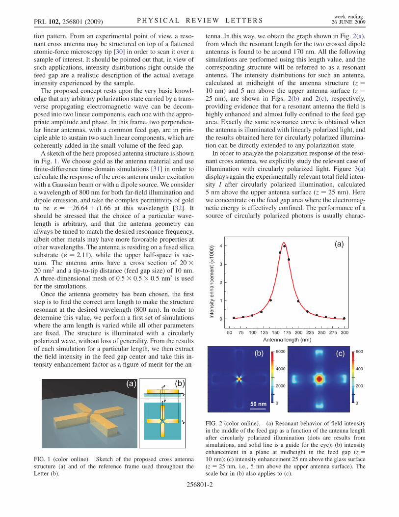
Once the antenna geometry has been chosen, the firststep is to find the correct arm length to make the structureresonant at the desired wavelength (800 nm). In order todetermine this value, we perform a first set of simulationswhere the arm length is varied while all other parametersare fixed. The structure is illuminated with a circularlypolarized wave, without loss of generality. From the resultsof each simulation for a particular length, we then extractthe field intensity in the feed gap center and take this in-tensity enhancement factor as a figure of merit for the an-
tenna. In this way, we obtain the graph shown in Fig. 2(a),from which the resonant length for the two crossed dipoleantennas is found to be around 170 nm. All the followingsimulations are performed using this length value, and thecorresponding structure will be referred to as a resonantantenna. The intensity distributions for such an antenna,calculated at midheight of the antenna structure (z ¼10 nm) and 5 nm above the upper antenna surface (z ¼25 nm), are shown in Figs. 2(b) and 2(c), respectively,providing evidence that for a resonant antenna the field ishighly enhanced and almost fully confined to the feed gaparea. Exactly the same resonance curve is obtained whenthe antenna is illuminated with linearly polarized light, andthe results obtained here for circularly polarized illumina-tion can be directly extended to any polarization state.In order to analyze the polarization response of the reso-
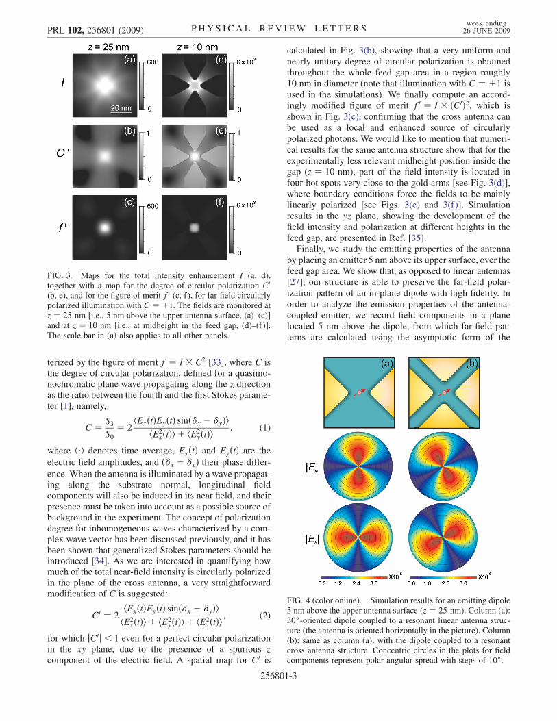
nant cross antenna, we explicitly study the relevant case ofillumination with circularly polarized light. Figure 3(a)displays again the experimentally relevant total field inten-sity I after circularly polarized illumination, calculated5 nm above the upper antenna surface (z ¼ 25 nm). Herewe concentrate on the feed gap area where the electromag-netic energy is effectively confined. The performance of asource of circularly polarized photons is usually charac-
FIG. 1 (color online). Sketch of the proposed cross antennastructure (a) and of the reference frame used throughout theLetter (b).
(c)(b)
0
200
600
0
2000
6000
4000 400
×
50 75 100 125 150 175 200 225 250 275 300
0
1
2
3
4 (a)
FIG. 2 (color online). (a) Resonant behavior of field intensityin the middle of the feed gap as a function of the antenna lengthafter circularly polarized illumination (dots are results fromsimulations, and solid line is a guide for the eye); (b) intensityenhancement in a plane at midheight in the feed gap (z ¼10 nm); (c) intensity enhancement 25 nm above the glass surface(z ¼ 25 nm, i.e., 5 nm above the upper antenna surface). Thescale bar in (b) also applies to (c).
PRL 102, 256801 (2009) P HY S I CA L R EV I EW LE T T E R Sweek ending26 JUNE 2009
256801-2
terized by the figure of merit f ¼ I � C2 [33], where C isthe degree of circular polarization, defined for a quasimo-nochromatic plane wave propagating along the z directionas the ratio between the fourth and the first Stokes parame-ter [1], namely,
C ¼ S3S0
¼ 2hExðtÞEyðtÞ sinð�x � �yÞi
hE2xðtÞi þ hE2
yðtÞi; (1)
where h�i denotes time average, ExðtÞ and EyðtÞ are the
electric field amplitudes, and ð�x � �yÞ their phase differ-ence. When the antenna is illuminated by a wave propagat-ing along the substrate normal, longitudinal fieldcomponents will also be induced in its near field, and theirpresence must be taken into account as a possible source ofbackground in the experiment. The concept of polarizationdegree for inhomogeneous waves characterized by a com-plex wave vector has been discussed previously, and it hasbeen shown that generalized Stokes parameters should beintroduced [34]. As we are interested in quantifying howmuch of the total near-field intensity is circularly polarizedin the plane of the cross antenna, a very straightforwardmodification of C is suggested:
C0 ¼ 2hExðtÞEyðtÞ sinð�x � �yÞihE2
xðtÞi þ hE2yðtÞi þ hE2
zðtÞi; (2)
for which jC0j< 1 even for a perfect circular polarizationin the xy plane, due to the presence of a spurious zcomponent of the electric field. A spatial map for C0 is
calculated in Fig. 3(b), showing that a very uniform andnearly unitary degree of circular polarization is obtainedthroughout the whole feed gap area in a region roughly10 nm in diameter (note that illumination with C ¼ þ1 isused in the simulations). We finally compute an accord-ingly modified figure of merit f0 ¼ I � ðC0Þ2, which isshown in Fig. 3(c), confirming that the cross antenna canbe used as a local and enhanced source of circularlypolarized photons. We would like to mention that numeri-cal results for the same antenna structure show that for theexperimentally less relevant midheight position inside thegap (z ¼ 10 nm), part of the field intensity is located infour hot spots very close to the gold arms [see Fig. 3(d)],where boundary conditions force the fields to be mainlylinearly polarized [see Figs. 3(e) and 3(f)]. Simulationresults in the yz plane, showing the development of thefield intensity and polarization at different heights in thefeed gap, are presented in Ref. [35].Finally, we study the emitting properties of the antenna
by placing an emitter 5 nm above its upper surface, over thefeed gap area. We show that, as opposed to linear antennas[27], our structure is able to preserve the far-field polar-ization pattern of an in-plane dipole with high fidelity. Inorder to analyze the emission properties of the antenna-coupled emitter, we record field components in a planelocated 5 nm above the dipole, from which far-field pat-terns are calculated using the asymptotic form of the
FIG. 4 (color online). Simulation results for an emitting dipole5 nm above the upper antenna surface (z ¼ 25 nm). Column (a):30�-oriented dipole coupled to a resonant linear antenna struc-ture (the antenna is oriented horizontally in the picture). Column(b): same as column (a), with the dipole coupled to a resonantcross antenna structure. Concentric circles in the plots for fieldcomponents represent polar angular spread with steps of 10�.
FIG. 3. Maps for the total intensity enhancement I (a, d),together with a map for the degree of circular polarization C0(b, e), and for the figure of merit f0 (c, f), for far-field circularlypolarized illumination with C ¼ þ1. The fields are monitored atz ¼ 25 nm [i.e., 5 nm above the upper antenna surface, (a)–(c)]and at z ¼ 10 nm [i.e., at midheight in the feed gap, (d)–(f)].The scale bar in (a) also applies to all other panels.
PRL 102, 256801 (2009) P HY S I CA L R EV I EW LE T T E R Sweek ending26 JUNE 2009
256801-3
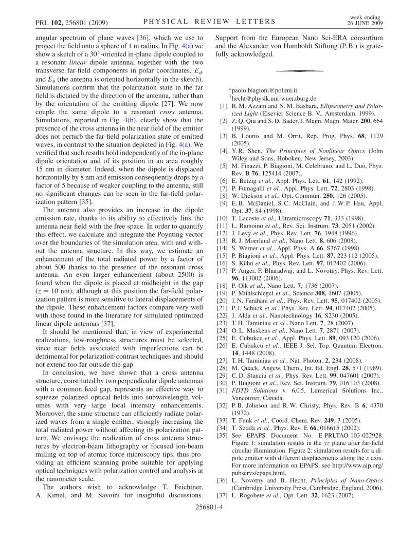
angular spectrum of plane waves [36], which we use toproject the field onto a sphere of 1 m radius. In Fig. 4(a) weshow a sketch of a 30�-oriented in-plane dipole coupled toa resonant linear dipole antenna, together with the twotransverse far-field components in polar coordinates, E�
and E� (the antenna is oriented horizontally in the sketch).Simulations confirm that the polarization state in the farfield is dictated by the direction of the antenna, rather thanby the orientation of the emitting dipole [27]. We nowcouple the same dipole to a resonant cross antenna.Simulations, reported in Fig. 4(b), clearly show that thepresence of the cross antenna in the near field of the emitterdoes not perturb the far-field polarization state of emittedwaves, in contrast to the situation depicted in Fig. 4(a). Weverified that such results hold independently of the in-planedipole orientation and of its position in an area roughly15 nm in diameter. Indeed, when the dipole is displacedhorizontally by 8 nm and emission consequently drops by afactor of 5 because of weaker coupling to the antenna, stillno significant changes can be seen in the far-field polar-ization pattern [35].
The antenna also provides an increase in the dipoleemission rate, thanks to its ability to effectively link theantenna near field with the free space. In order to quantifythis effect, we calculate and integrate the Poynting vectorover the boundaries of the simulation area, with and with-out the antenna structure. In this way, we estimate anenhancement of the total radiated power by a factor ofabout 500 thanks to the presence of the resonant crossantenna. An even larger enhancement (about 2500) isfound when the dipole is placed at midheight in the gap(z ¼ 10 nm), although at this position the far-field polar-ization pattern is more sensitive to lateral displacements ofthe dipole. These enhancement factors compare very wellwith those found in the literature for simulated optimizedlinear dipole antennas [37].
It should be mentioned that, in view of experimentalrealizations, low-roughness structures must be selected,since near fields associated with imperfections can bedetrimental for polarization-contrast techniques and shouldnot extend too far outside the gap.
In conclusion, we have shown that a cross antennastructure, constituted by two perpendicular dipole antennaswith a common feed gap, represents an effective way tosqueeze polarized optical fields into subwavelength vol-umes with very large local intensity enhancements.Moreover, the same structure can efficiently radiate polar-ized waves from a single emitter, strongly increasing thetotal radiated power without affecting its polarization pat-tern. We envisage the realization of cross antenna struc-tures by electron-beam lithography or focused ion-beammilling on top of atomic-force microscopy tips, thus pro-viding an efficient scanning probe suitable for applyingoptical techniques with polarization control and analysis atthe nanometer scale.
The authors wish to acknowledge T. Feichtner,A. Kimel, and M. Savoini for insightful discussions.
Support from the European Nano Sci-ERA consortiumand the Alexander von Humboldt Stiftung (P. B.) is grate-fully acknowledged.
*[email protected]†[email protected]
[1] R.M. Azzam and N.M. Bashara, Ellipsometry and Polar-ized Light (Elsevier Science B. V., Amsterdam, 1999).
[2] Z. Q. Qiu and S.D. Bader, J. Magn. Magn. Mater. 200, 664(1999).
[3] B. Lounis and M. Orrit, Rep. Prog. Phys. 68, 1129(2005).
[4] Y. R. Shen, The Principles of Nonlinear Optics (JohnWiley and Sons, Hoboken, New Jersey, 2003).
[5] M. Finazzi, P. Biagioni, M. Celebrano, and L. Duo, Phys.Rev. B 76, 125414 (2007).
[6] E. Betzig et al., Appl. Phys. Lett. 61, 142 (1992).[7] P. Fumagalli et al., Appl. Phys. Lett. 72, 2803 (1998).[8] W. Dickson et al., Opt. Commun. 250, 126 (2005).[9] E. B. McDaniel, S. C. McClain, and J.W. P. Hsu, Appl.
Opt. 37, 84 (1998).[10] T. Lacoste et al., Ultramicroscopy 71, 333 (1998).[11] L. Ramoino et al., Rev. Sci. Instrum. 73, 2051 (2002).[12] J. Levy et al., Phys. Rev. Lett. 76, 1948 (1996).[13] R. J. Moerland et al., Nano Lett. 8, 606 (2008).[14] S. Werner et al., Appl. Phys. A 66, S367 (1998).[15] P. Biagioni et al., Appl. Phys. Lett. 87, 223 112 (2005).[16] S. Kuhn et al., Phys. Rev. Lett. 97, 017402 (2006).[17] P. Anger, P. Bharadwaj, and L. Novotny, Phys. Rev. Lett.
96, 113002 (2006).[18] P. Olk et al., Nano Lett. 7, 1736 (2007).[19] P. Muhlschlegel et al., Science 308, 1607 (2005).[20] J. N. Farahani et al., Phys. Rev. Lett. 95, 017402 (2005).[21] P. J. Schuck et al., Phys. Rev. Lett. 94, 017402 (2005).[22] J. Alda et al., Nanotechnology 16, S230 (2005).[23] T.H. Taminiau et al., Nano Lett. 7, 28 (2007).[24] O. L. Muskens et al., Nano Lett. 7, 2871 (2007).[25] E. Cubukcu et al., Appl. Phys. Lett. 89, 093 120 (2006).[26] E. Cubukcu et al., IEEE J. Sel. Top. Quantum Electron.
14, 1448 (2008).[27] T.H. Taminiau et al., Nat. Photon. 2, 234 (2008).[28] M. Quack, Angew. Chem., Int. Ed. Engl. 28, 571 (1989).[29] C. D. Stanciu et al., Phys. Rev. Lett. 99, 047601 (2007).[30] P. Biagioni et al., Rev. Sci. Instrum. 79, 016 103 (2008).[31] FDTD Solutions v. 6.0.5, Lumerical Solutions Inc.,
Vancouver, Canada.[32] P. B. Johnson and R.W. Christy, Phys. Rev. B 6, 4370
(1972).[33] T. Funk et al., Coord. Chem. Rev. 249, 3 (2005).[34] T. Setala et al., Phys. Rev. E 66, 016615 (2002).[35] See EPAPS Document No. E-PRLTAO-103-022928.
Figure 1: simulation results in the yz plane after far-fieldcircular illumination. Figure 2: simulation results for a di-pole emitter with different displacements along the x axis.For more information on EPAPS, see http://www.aip.org/pubservs/epaps.html.
[36] L. Novotny and B. Hecht, Principles of Nano-Optics(Cambridge University Press, Cambridge, England, 2006).
[37] L. Rogobete et al., Opt. Lett. 32, 1623 (2007).
PRL 102, 256801 (2009) P HY S I CA L R EV I EW LE T T E R Sweek ending26 JUNE 2009
256801-4