crowned ridge i and ii, sd electromagnetic interference
TRANSCRIPT

Crowned Ridge, LLC
Crowned Ridge I and II, SD Electromagnetic Interference Analysis
Crowned Ridge Wind LLC

Crowned Ridge LLC
Electromagnetic Interference
2
The following document was prepared by WindLogics Inc. (WindLogics), an indirect wholly-owned subsidiary of NextEra Energy Resources, LLC (NEER) for the use of Crowned Ridge Wind, LLC, as an indirect wholly-owned subsidiary of NEER. WindLogics Inc. has prepared this report based on available government information by the Federal Communications Commission (FCC) and internal analysis methods. We cannot guarantee the accuracy of the data collected by the FCC. Microwave tower and link information may be inaccurate or incomplete due to FCC applicant error.

Crowned Ridge LLC
Electromagnetic Interference
3
Executive Summary WindLogics, an affiliate of Crowned Ridge Wind LLC (Crowned Ridge) assessed the potential for interference of licensed communication links in close proximity to the proposed Crowned Ridge Wind Project area for the purposes of determining exclusion zones to aid the design of a proposed wind energy generation project. This report summarizes the microwave links and towers along with local cellular towers, media towers (AM and FM), television, and aviation towers, identified within and near the assessment area. A review of the Federal Communications Commission (FCC) national database and the Universal Licensing System was conducted to identify these possible constraints. Wind turbine offset distances were taken in consideration for the design of the wind turbine array. Electromagnetic analysis results show that interference is not expected to impact nearby microwave, AM, FM, cellular, TV, and aviation towers based on the array design. The analysis is current as of August 20th, 2018. WindLogics recommends a refresh of this analysis if the proposed wind energy generation project has not been constructed after two years. This report only provides analysis for licensed radio towers and links found within the FCC database. Many local municipalities (police, fire, etc.) do not license microwave links, WindLogics recommends that Crowned Ridge LLC coordinate with the appropriate local municipality officials. Also not included within the database are microwave towers and links utilized by the Federal government (Dept. of Defense, Dept. of Commerce, etc.), again for public safety concerns. A letter stating “No Harmful Interference Anticipated” has been received from the National Telecommunications and Information Agency (NTIA) concerning the DOA (Agriculture), DOC (Commerce), and DON (Navy). The DOE (Energy) had considerable issues with turbine placement in the area and the developer is currently working with the agency to mitigate their concerns at the site.

Crowned Ridge LLC
Electromagnetic Interference
4
Crowned Ridge Wind, SD – Electromagnetic Interference WindLogics, an affiliate of Crowned Ridge Wind LLC (Crowned Ridge) assessed the potential for interference of licensed communication links in close proximity to the proposed Crowned Ridge Wind Project area for the purposes of determining exclusion zones to aid the design of a proposed wind energy generation project. This report summarizes the microwave links and towers along with local cellular towers, media towers (AM and FM), television, and aviation towers, identified within and near the assessment area. A review of the FCC national database and the Universal Licensing System was conducted to identify these possible constraints. Wind turbine offset distances were taken into consideration for the design of the wind turbine array. The site is located in Codington, Grant and Deuel Counties, South Dakota, roughly 15 kilometers east of the city of Watertown, South Dakota. Figure 1 below, depicts the project location of Crowned Ridge Wind.
Figure 1: Crowned Ridge Wind Project Location
· .,,. \ Codington, Grant 1\ ' and Deuel County, , South Dakota: \ Crowned Ridge l \/Vind Project
0 20 40 80Miu

Crowned Ridge LLC
Electromagnetic Interference
5
Turbine Technology Crowned Ridge Wind is a proposed hybrid wind energy generation site that consists of 266 turbine locations. The layout is composed of 256 (238 primary and 18 alternate) GE2.3-116 turbines (2.3MW rated capacity, 116m rotor diameter (RD)), 15 GE2.1-116 turbines (2.1MW rated capacity, 116m rotor diameter (RD)) and 13 GE1.715-103 turbines (1.715MW rated capacity, 103m RD) for a total capacity of 601.2 MW. Turbine layout details are included in Table 1 and Figure 2
Turbine Technology GE2.3-116 / GE2.1-116 GE1.715-103
Turbine Count 238(18) / 15 / 13 Hub Height (m) 90 / 80 / 80
Rotor Diameter (m) 116 / 116 / 103 Turbine Rated Power (MW) 2.3 / 2.1 / 1.715
Total Capacity (MW) 601.2
Table 1: Crowned Ridge Layout Summary
Figure 2: Crowned Ridge Wind Turbine Technology Allocation
WindLogics
Legend Tu.rblnc Typci
• OE1 .715•10J,80
• GE2.3-118,SM>
• GE2.1-118-80
c:::J 'rara•t Project Areas

Crowned Ridge LLC
Electromagnetic Interference
6
Data Sources Within the United States, the location of industrial and commercial telecommunication systems, including microwave links, are collected and maintained by the Wireless Telecommunications Bureau (WTB), a division of the FCC. This data is made publicly available through the ULS database, which contains licensing information on both current and permit pending facilities for microwave, cellular, media, and several radio services utilized by private industry (non-Federal telecommunication systems). License information supplied within the ULS database is updated daily, and is dependent upon information provided by each individual applicant. WindLogics used several data sources (ESRI satellite imagery, Google Earth, etc.) of high resolution imagery to aid in assessing the accuracy of the geographic locations of each microwave tower with links intersecting the project boundary or area of interest (AOI). Methodology The ULS database, described earlier, was used to identify the microwave towers, microwave links, cellular, AM, FM, and aviation towers within a 25-kilometer radius that may impact the Crowned Ridge Wind Farm. Television towers were identified within a 100-kilometer radius. The database provides detailed information for each radio tower and link, which was used to calculate turbine exclusion zones to ensure interference compliance. Exclusion zones for wind turbines near microwave links are calculated using a theory proposed by Bacon (2002), which identifies the radius of the 2nd Fresnel zone, a theoretical sphere representative of a propagating radio wave, as an appropriate offset distance. Calculations of the 2nd Fresnel zone can be determined by:
Where:
d1, d2 = distances from each end of the radio path. λ= wavelength of the corresponding radio frequency.
( 1 ) 2n d Fresne l z on e R'adius = 2.:Ld1 d2
d1 + dz

Crowned Ridge LLC
Electromagnetic Interference
7
To account for precision errors within the ULS database, and to further reduce the potential for interference from a wind turbine, a Worst Case Fresnel Zone (WCFZ) was calculated for each microwave link. The WCFZ provides the maximum offset distance required, and is determined by the 2nd Fresnel zone radius obtained at the midpoint of the link, where d1 = d2. Adjusting Eq. 1 to calculate the WCFZ in meters yields the following:
Where: D = distance between the transmitter and receiver towers. F = frequency in GHz. n = Fresnel zone, which for the 2nd Fresnel Zone n = 2. The calculated radius distance from Eq. 2 provides a three-dimensional turbine exclusion zone around each microwave link that can be used to guide wind turbine array design. In addition to the WCFZ calculated for each microwave link, WindLogics applies an offset of one-half RD plus 10 meter to account for turbine blade overhang. A turbine overhang offset using a 116 m turbine technology is included within this analysis to represent the GE2.5-116 wind turbine generator. The WTB cannot provide quality assurance for every license within the ULS database, so accuracy of the data relies on applicant certifications, and, in extreme cases, license audits. It has been WindLogics’ experience that most inaccuracies occur with regard to the location of the radio towers, where approximation or lack of precision of the geographic coordinates can result in a difference in the position of the tower by as much as 500 meters. To fully account for these location errors, WindLogics recommends on-site verification to identify the exact location of the transmitter and receiver towers. However, for this analysis, WindLogics used high-resolution satellite imagery to identify possible tower location errors. Most microwave, media, and cellular towers extend well over 80m above ground level, and can be clearly viewed within high resolution satellite imagery. Each tower that may impact the project boundary was investigated for potential location error. Adjustments to the location of the microwave, media, and cellular towers are only made if clear evidence from the satellite imagery shows an inaccuracy.
( 2 ) WCFZ = 17-32 j4~
Crowned Ridge LLC
Electromagnetic Interference
8
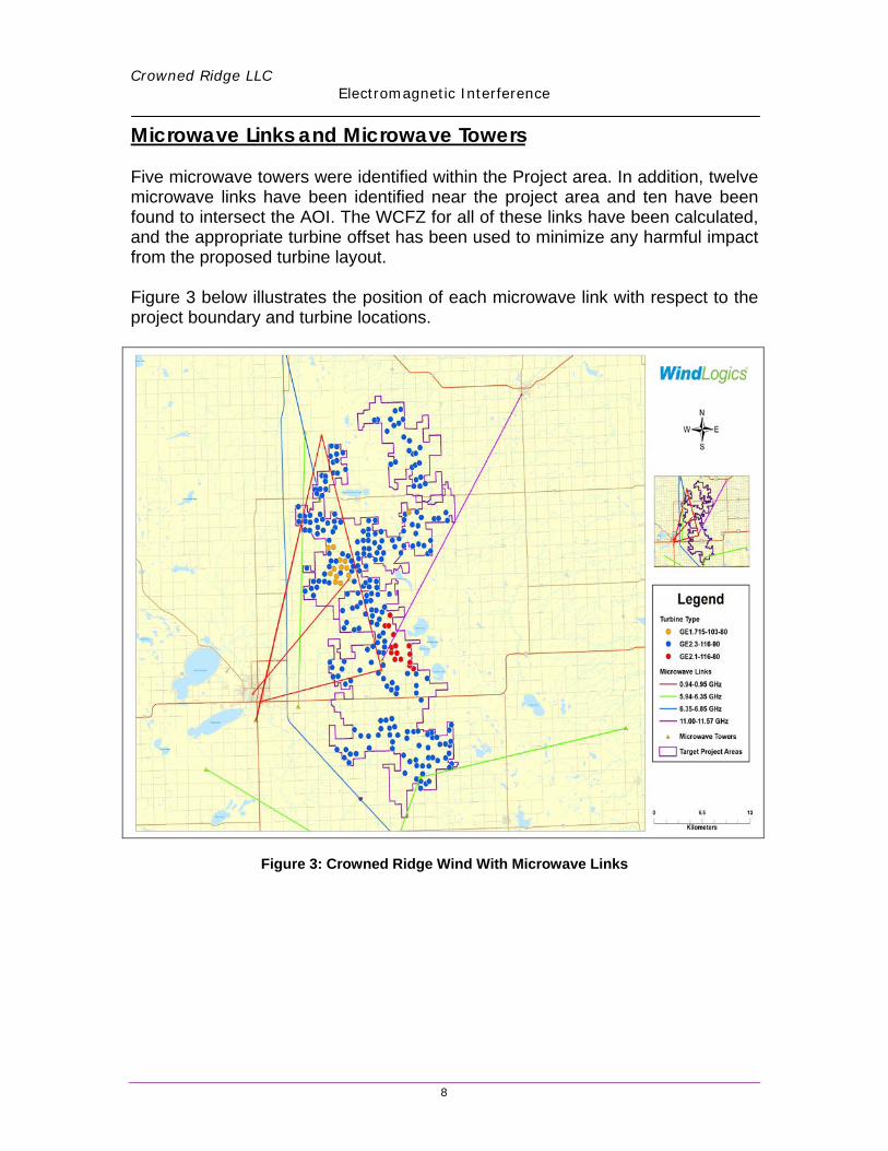
Microwave Links and Microwave Towers Five microwave towers were identified within the Project area. In addition, twelve microwave links have been identified near the project area and ten have been found to intersect the AOI. The WCFZ for all of these links have been calculated, and the appropriate turbine offset has been used to minimize any harmful impact from the proposed turbine layout. Figure 3 below illustrates the position of each microwave link with respect to the project boundary and turbine locations.
Figure 3: Crowned Ridge Wind With Microwave Links
Wind Logics
Legend
Mk:rowave Unks
- 0.94-0.95 GHz
5.94-6.35 GHz
- 6.35-6.85 GHz
- 11,(M>-11 .57 GHz
•• KHometen
"

Crowned Ridge LLC
Electromagnetic Interference
9
Table 2 provides more detailed information on each microwave link in proximity to the area with the calculated WCFZ. ID STATUS TRANSMITTER CALLSIGN MICROWAVE NAME BAND FREQ (GHz) WCFZ (m) BEAM LENGTH (Km)
1 Active WHI958 EAST RIVER ELECTRIC POWER COOP 6.12 30.04 36.842 Active WHI958 EAST RIVER ELECTRIC POWER COOP 6.12 30.04 36.843 Active WIA856 EAST RIVER ELECTRIC POWER COOP 6.26 26.19 28.604 Active WIA856 EAST RIVER ELECTRIC POWER COOP 6.26 29.72 36.845 Active WIA856 EAST RIVER ELECTRIC POWER COOP 6.26 26.16 28.546 Active WIA856 EAST RIVER ELECTRIC POWER COOP 6.26 29.72 36.847 Active WIA858 EAST RIVER ELECTRIC POWER COOP 6.09 28.44 32.868 Active WIA858 EAST RIVER ELECTRIC POWER COOP 6.09 28.41 32.789 Active WIA895 EAST RIVER ELECTRIC POWER COOP 5.95 26.83 28.54
10 Active WIA895 EAST RIVER ELECTRIC POWER COOP 5.95 26.83 28.5411 Active WLP539 ALPHA 3E LICENSEE LLC 0.95 74.44 35.1312 Active WLP540 ALPHA 3E LICENSEE LLC 0.95 74.52 35.1313 Active WMG235 ALPHA 3E LICENSEE LLC 0.94 68.07 29.1914 Active WMG236 ALPHA 3E LICENSEE LLC 0.95 51.55 16.8215 Active WMN496 New Cingular Wireless PCS, LLC 6.63 24.58 26.6816 Active WPOR475 EAST RIVER ELECTRIC POWER COOP 6.35 27.84 32.7817 Active WPOR475 EAST RIVER ELECTRIC POWER COOP 6.35 27.84 32.7818 Active WPVJ218 New Cingular Wireless PCS, LLC 6.85 24.18 26.6819 Active WQDT286 Northern Border Pipeline Company 5.95 29.85 35.3220 Active WQDT287 Northern Border Pipeline Company 6.20 29.24 35.3221 Active WQDT287 Northern Border Pipeline Company 6.20 30.67 38.8522 Active WQDT287 Northern Border Pipeline Company 6.20 30.22 37.7423 Active WQDT288 Northern Border Pipeline Company 5.95 30.86 37.7424 Active WQDT289 Northern Border Pipeline Company 5.97 31.23 38.8525 Active WQME671 TMRG BROADCASTING, LLC 0.95 54.56 18.8926 Active WQYT404 RC Technologies 11.00 22.48 37.0427 Active WQYT405 RC Technologies 11.57 21.92 37.04
Table 2: Detailed Information on Microwave Links That Intersect the Project Boundary
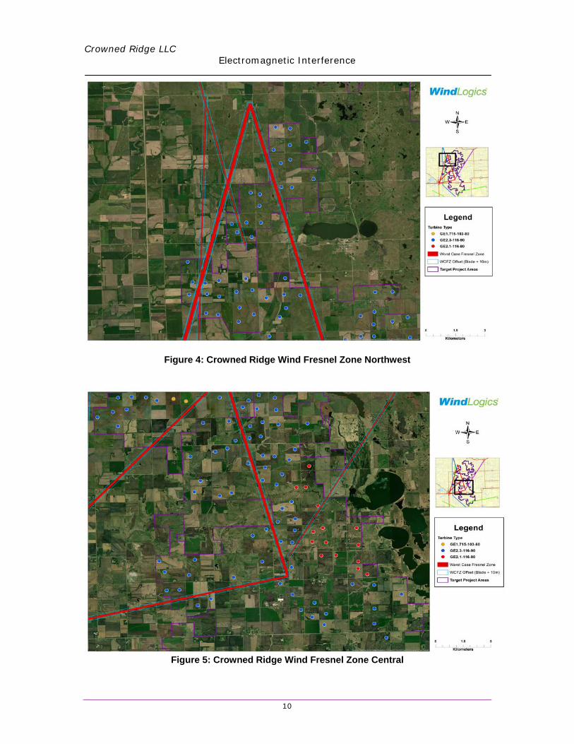
There are a number of links that are within relatively close proximity to turbines. The Worst Case Fresnel Zone was calculated for each microwave link and a conservative offset of 68 meters was used to reduce the probability of harmful interference. Figures 4-6 provide aerial imagery of the turbine layout relative to the Fresnel zones and their offsets that intersect the project boundary.
Crowned Ridge LLC
Electromagnetic Interference
10
Figure 4: Crowned Ridge Wind Fresnel Zone Northwest
Figure 5: Crowned Ridge Wind Fresnel Zone Central
Wind Logics
Legend
GE1.715°103-IO
e GE2.3°11e.90
e GE2, M 18,80
Kfllom•ten
WindLogics
Legend Turbine Type
• GEt .715-103-40
e GE?.3-116-90
• GE2.1.11s.ao
- Wont CaH FtHnel Zone
CJ WCFZ Offstl {Blad•• IOm)

Crowned Ridge LLC
Electromagnetic Interference
11
Figure 6: Crowned Ridge Wind Fresnel Zone South
Cellular Towers One cellular tower was identified within the project boundary. Four additional cellular towers were discovered within 25 km of the project boundary and are identified in Table 3 and figure 7. Harmful interference associated with cellular towers is not likely as cellular transitions or packet switching occurs when a cellular link becomes unavailable. ID STATUS CALLSIGN LICENSEE LATITUDE LONGITUDE DISTANCE TO AOI(km)
1 Active KNKN368 Rural Cellular Corporation 44.91581 -96.96506 0.002 Active KNKN368 Rural Cellular Corporation 44.66469 -96.80867 13.953 Active KNKN368 Rural Cellular Corporation 45.11611 -97.04653 2.044 Active KNKN368 Rural Cellular Corporation 44.90667 -96.70056 6.355 Active KNKN368 Rural Cellular Corporation 44.73344 -96.68386 11.27
Table 3: Cellular Towers within 25 km of the Project Boundary
WindLogics
Legend Turbine Type
e GE1 .71.S.103...80
e OE2.3-116-to
e GE2.1-118.-80
.. wor11 case Fttsriel zone
C] WC:FZ Offst1 {Blade + IOm)
c:J Target Profect Areas
Crowned Ridge LLC
Electromagnetic Interference
12
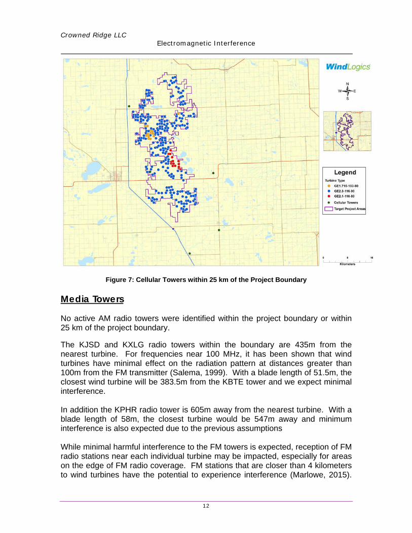
Figure 7: Cellular Towers within 25 km of the Project Boundary Media Towers No active AM radio towers were identified within the project boundary or within 25 km of the project boundary. The KJSD and KXLG radio towers within the boundary are 435m from the nearest turbine. For frequencies near 100 MHz, it has been shown that wind turbines have minimal effect on the radiation pattern at distances greater than 100m from the FM transmitter (Salema, 1999). With a blade length of 51.5m, the closest wind turbine will be 383.5m from the KBTE tower and we expect minimal interference. In addition the KPHR radio tower is 605m away from the nearest turbine. With a blade length of 58m, the closest turbine would be 547m away and minimum interference is also expected due to the previous assumptions While minimal harmful interference to the FM towers is expected, reception of FM radio stations near each individual turbine may be impacted, especially for areas on the edge of FM radio coverage. FM stations that are closer than 4 kilometers to wind turbines have the potential to experience interference (Marlowe, 2015).
r-
r
~ - ~.· --------w-~ I I ·- i 1
WindLogics
Legend Turbine Type
e GE1.715-103-80
e GE2.3-1 16-90
• GE2.1-116-80
• Cellu lar Towers
11
Crowned Ridge LLC
Electromagnetic Interference
13
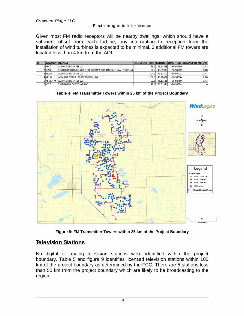
Given most FM radio receptors will be nearby dwellings, which should have a sufficient offset from each turbine, any interruption to reception from the installation of wind turbines is expected to be minimal. 3 additional FM towers are located less than 4 km from the AOI. ID CALLSIGN LICENSEE FREQUENCY (MHz) LATITUDE LONGITUDE DISTANCE TO AOI(km)
1 KIXX ALPHA 3E LICENSEE LLC 96.1 45.17528 -96.98750 1.482 KJSD SOUTH DAKOTA BOARD OF DIRECTORS FOR EDUCATIONAL TELECOM 90.3 45.01939 -96.94519 0.003 KKSD ALPHA 3E LICENSEE LLC 104.3 45.17500 -96.98722 1.434 KPHR ARMADA MEDIA - WATERTOWN, INC. 106.3 45.10472 -96.98806 0.005 KSDR-FM ALPHA 3E LICENSEE LLC 92.9 45.17528 -96.98750 1.436 KXLG TMRG BROADCASTING, LLC 99.1 45.01944 -96.94528 0
Table 4: FM Transmitter Towers within 25 km of the Project Boundary
Figure 8: FM Transmitter Towers within 25 km of the Project Boundary
Television Stations No digital or analog television stations were identified within the project boundary. Table 5 and figure 9 identifies licensed television stations within 100 km of the project boundary as determined by the FCC. There are 5 stations less than 50 km from the project boundary which are likely to be broadcasting to the region.
-
WindLogics
Legend Turbine-Typc-
• GE1.715-10J.flQ
• GEZ.3-116-90
e GEZ.1 -11&-80
■ FMTowers
CJ Targel Projecl Arl!!a!
0 U " l-l_i_Kiom¾t-.,.~~~

Crowned Ridge LLC
Electromagnetic Interference
14
ID CALLSIGN LICENSEE SERVICE CHANNEL ERP Latitude Longitude DISTANCE TO AOI(km)1 KABY-TV HOAK MEDIA OF DAKOTA LICENSE, LLC DT 28 54. kW 45.10640 -97.89959 68.092 KDLO-TV YOUNG B/CING OF SIOUX FALLS, INC., DEBTOR-IN-POSSESSION DT 3 14.4 kW 44.96561 -97.58978 44.943 KDSD-TV SOUTH DAKOTA BOARD OF DIRECTORS FOR EDUCATIONAL TELECOMMUDT 17 19. kW 45.49830 -97.67479 66.704 KESD-TV SOUTH DAKOTA BOARD OF DIRECTORS FOR EDUCATIONAL TELECOMMUDT 8 15. kW 44.33781 -97.22867 56.835 KWCM-TV WEST CENTRAL MINNESOTA EDUCATIONAL TELEVISION COMPANY DT 31 288. kW 45.16751 -96.00093 60.726 K16CP MINNESOTA VALLEY TV IMPROVEMENT TX 16 1.67 kW 44.80471 -95.58061 96.217 K18DI MINNESOTA VALLEY TV IMPROVEMENT TX 18 1.67 kW 44.80471 -95.58061 96.218 K22DO MINNESOTA VALLEY TV IMPROVEMENT TX 22 1.65 kW 44.80471 -95.58061 96.219 K24CS MINNESOTA VALLEY TV IMPROVEMENT TX 24 1.65 kW 44.8047 -95.58061 96.21
10 K26DG MINNESOTA VALLEY TV IMPROVEMENT TX 26 1.65 kW 44.80471 -95.58061 96.2111 K32DK INDEPENDENT COMMUNICATIONS, INC. TX 32 11.4 kW 44.87001 -97.11397 10.7512 K32DR MINNESOTA VALLEY TV IMPROVEMENT TX 32 1.45 kW 44.80471 -95.58061 96.2113 K35DK MINNESOTA VALLEY TV IMPROVEMENT TX 35 1.45 kW 44.8047 -95.58061 96.2114 K35GR RED RIVER BROADCAST CO., LLC TX 35 11.9 kW 44.4875 -97.23927 43.2115 K40FZ RED RIVER BROADCAST CO., LLC TX 40 13.5 kW 44.33941 -96.76895 50.1316 K42FI RED RIVER BROADCAST CO., LLC TX 42 10. kW 44.87111 -97.10977 10.7517 K45DJ MINNESOTA VALLEY TV IMPROVEMENT TX 45 1.45 kW 44.8047 -95.58061 96.2118 K47EA MINNESOTA VALLEY TV IMPROVEMENT TX 47 1.45 kW 44.8047 -95.58061 96.2119 K47IC RED RIVER BROADCAST CO., LLC TX 47 7.8 kW 45.1753 -96.98756 1.4820 K50DG INDEPENDENT COMMUNICATIONS, INC. TX 50 0.45 kW 44.3008 -96.76705 54.5721 K61AU MINNESOTA VALLEY TV IMPROVEMENT CORP TX 61 1.13 kW 44.8047 -95.58061 96.2122 K63AU MINNESOTA VALLEY TV IMPROVEMENT CORP TX 63 1.13 kW 44.8047 -95.58061 96.2123 K65BA MINNESOTA VALLEY TV IMPROVEMENT CORP TX 65 1.13 kW 44.80471 -95.58061 96.2124 K67AN MINNESOTA VALLEY TV IMPROVEMENT CORP TX 67 0.707 kW 44.80471 -95.58061 96.2125 K69DP MINNESOTA VALLEY TV IMPROVEMENT CORP TX 69 0.734 kW 44.80471 -95.58061 96.21
Table 5: Television Stations within 100 km of the Project Boundary
http://www.thebestpageintheuniverse.net/c.cgi?u=irule
Figure 9: Television Stations within 100 km of the Project Boundary While the impact of wind turbines on digital television reception is not well known due to limited cases and testing, any interference is expected to be limited to areas near the edge of station reception, areas near a turbine that is within the line-of-sight between the transmit tower and receptor, and areas of complex topography (OfCom, 2009). Most of the stations within 100km are low power stations or translator stations and have limited range and are not anticipated to experience reception degradation. There are five full power stations KABY-TV, KDLO-TV, KDSD-TV, KESD-TV, and KWCM-TV which have a possibility of experiencing reception degradation if the proposed wind farm is located in the line-of-sight. It is important to note that this assessment is based on broad assumptions, as it is difficult to accurately pinpoint the impact a large wind farm may have on each individual household due to a large number of external variables (topography, weather, antennae, etc.) which affect the propagation of the television radio signal.

Crowned Ridge LLC
Electromagnetic Interference
15
Aviation Towers No active Aviation towers were identified within the project boundary or within 25 kilometers of the area of interest. While no harmful interference is expected for the aviation towers; Crowned Ridge Wind is subject to a Federal Aviation Agency (FAA) to determine any exclusion zones. Proposed turbine locations will maintain the standard appropriate offset distances in addition to any setbacks set by the agency to minimize harmful impact. Conclusion and Recommendations WindLogics analyzed the potential for wind turbine interference on licensed microwave links located within the proposed Crowned Ridge Wind Project energy generation site. This report summarizes the microwave towers, microwave links, cellular towers, media towers, television towers, and aviation towers within and near the project boundary. Eight microwave links were found to intersect the project boundary, and an appropriate offset to the WCFZ has been utilized to mitigate harmful interference from the proposed turbine layout. No interference from the proposed turbine layout is expected near microwave, AM, FM, cellular, aviation, and TV towers. This analysis is current as of August 20th, 2018. WindLogics recommends a refresh of this analysis if the proposed wind energy generation project has not been constructed after two years. It is important to note that this report only provides analysis for licensed radio towers and links found within the FCC-ULS database. Many local municipalities (police, fire, etc.) do not license microwave links, WindLogics recommends Crowned Ridge Wind LLC coordinate with the appropriate local municipality officials. Also not included within the database are microwave towers and links utilized by the Federal government (Dept. of Defense, Dept. of Commerce, etc.),

Crowned Ridge LLC
Electromagnetic Interference
16
again for public safety concerns. A Federal communications study by the National Telecommunications and Information Agency (NTIA) has been conducted stating no harmful interference is expected in the project area. References Bacon, David F.,”A proposed method for establishing an exclusion zone around a terrestrial fixed
radio link outside of which a wind turbine will cause negligible degradation of the radio link performance.” http://www.ofcom.org.uk/radiocomms/ifi/licensing/classes/fixed/Windfarms/windfarmdavidbacon.pdf,Version 1.1,Oct 2002.
Ofcom, “Tall structures and their impact on broadcast and other wireless services.”
http://www.ofcom.org.uk/radiocomms/ifi/licensing/classes/fixed/Windfarms/tall structures/tall structures.pdf, August 2009.
Marlowe, Frank. "The Importance of Electromagnetic-impact Analyses for Wind
Permitting." Windpower Engineering & Development. Broadcast Wind, 2015. Web. 19 July 2017.