crso series ceafo series - comitale national · comitale national inc. crso series ceafo series...
TRANSCRIPT
C O M I T A L E N A T I O N A L I N C .
CRSO SERIESCEAFO SERIES
Engineering/Operation &Installation Instructions
Comitale National Inc. 1683 B Winchester Road, Bensalem, PA 19020 Phone: 215-244-9650Fax: 215-244-9679Email: [email protected] www.comitalenational.com
Original Equipment Manufacturer of Custom Packaged Terminal Air Conditioners andNational H.V.A.C. Parts Distributor

PTAC Check, Test and Start Worksheet . . . . . . . . . . . . . . . . . . . . . . . . . . . . . . . . . . . . . . . . . . . . . . .
Troubleshooting Chart . . . . . . . . . . . . . . . . . . . . . . . . . . . . . . . . . . . . . . . . . . . . . . . . . . . . . . . . . . . .
Product Code Sheet . . . . . . . . . . . . . . . . . . . . . . . . . . . . . . . . . . . . . . . . . . . . . . . . . . . . . . . . . . . . . . . . . 8
Scheduled Maintenance . . . . . . . . . . . . . . . . . . . . . . . . . . . . . . . . . . . . . . . . . . . . . . . . . . . .. . . . .20
Table of Contents
Warranty - Standard Limited Warranty . . . . . . . . . . . . . . . . . . . . . . . . . . . . . . . . . . . . .Page 12
Comitale National Inc.
Comitale National Inc.Page 2
Engineering Information - Specifications . . . . . . . . . . . . . . . . . . . . . . . . . . . . . . . . . . . . . . . . . . . 5 - 7
Table of Contents. . . . . . . . . . . . . . . . . . . . . . . . . . . . . . . . . . . . . . . . . . . . . . . . . . . . . . . . . . . . . . . . . 2
Warranty - Optional Four Year Extended Warranty. . . . . . . . . . . . . . . . . . . . . . . . . . . . . . . . . . .
Wall Opening Requirements . . . . . . . . . . . . . . . . . . . . . . . . . . . . . . . . . . . . . . . . . . . . . . . . . . . .. . .10
Receiving Equipment/ Dimensional Data . . . . . . . . . . . . . . . . . . . . . . . . . . . . . . . . . . . . . . . . . . . . . . 9
Recommended Spare Parts . . . . . . . . . . . . . . . . . . . . . . . . . . . . . . . . . . . . . . . . . . . . . . . . . . . . . . . . .
Chassis. . . . . . . . . . . . . . . . . . . . . . . . . . . . . . . . . . . . . . . . . . . . . . . . . . . . . . . . . . . . . . . . . . . . .15
21222324-2526
New Construction, Additions or Renovations. . . . . . . . . . . . . . . . . . . . . . . . . . . . . . . . . . . . . . . .3
Replacing With The CRSO/CEAFO Series . . . . . . . . . . . . . . . . .. . . . . . . . . . . . . . . . . . . .. . . . . 4
Installation - Considerations . . . . . . . . . . . . . . . . . . . . . . . . . . . . . . . . . . . . . . . . . . . . . . . . . . . . . .10
Masonry and Thick Wall Applications . . . . . . . . . . . . . . . . . . . . . . . . . . . . . . . . . . . . . . . . . . . . . . . .11
General Information Electrical Service . . . . . . . . . . . . . . . . . . . . . . . . . . . . . . . . . . . . . . . . . . . . . . .12
Typica Installation . . . . . . . . . . . . . . . . . . . . . . . . . . . . . . . . . . . . . . . . . . . . . . . . . . . . . . . . . . . . . . .13
Installation Instructions Louver Frame . . . . . . . . . . . . . . . . . . . . . . . . . . . . . . . . . . . . . . . . . . . . . . . .14
Installation Instructions Wall Sleeve Extensions. . . . . . . . . . . . . . . . . . . . . . . . . . . . . . . . . . . . .. . . 14
Panel And Thin Wall Applications . . . . . . . . . . . . . . . . . . . . . . . . . . . . . . . . . . . . . . . . . . . . . . . . . . .15
Louver/Start Up - Equipment . . . . . . . . . . .. . . . . . . . . . . . . . . . . . . . . . . . . . . . . . . . . . . . . . . . . . . . . .16
Sub Base Hydronic Heat Section . . . . . . . . . . . . . . . . . . . . . . . . . . . . . . . . . . . . . . . . . . . . . . . . . . . .17 - 18
Electrical Sub Base Installation . . . . . . . . . . . . . . . . . . . . . . . . . . . . . . . . . . . . . . . . . . . . . . . . . . . . . 19
Recommended Spare Parts . . . . . . . . . . . . . . . . . . . . . . . . . . . . . . . . . . . . . . . . . . . . . . . . . . .. . . . . .20
Troubleshooting Spare Parts . . . . . . . . . . . . . . . . . . . . . . . . . . . . . . . . . . . . . . . . . . . . . . . . . . . . . . . .21
Warranty Standard . . . . . . . . . . . . . . . . . . . . . . . . . . . . . . . . . . . . . . . . . . . . . . . . . . . . . . . . . . . . . . . 22
Warranty Optional Four Year Standard . . . . . . . . . . . . . . . . . . . . . . . . . . . . . . . . . . . . . . . . . . . . . . . .23 - 24
Warranty Card . . . . . . . . . . . . . . . . . . . . . . . . . . . . . . . . . . . . . . . . . . . . . . . . . . . . . . . . . . . . . . . . . . .25
PTAC Check, Test and Start up Worksheet. . . . . . . . . . . . . . . . . . . . . . . . . . . . . . . . . . . . . . . . . . . .26
Notes . . . . . . . . . . . . . . . . . . . . . . . . . . . . . . . . . . . . . . . . . . . . . . . . . . . . . . . . . . . . . . . . . . . . . . . . . . . . .27
The Ideal Solution: New Construction, Additions or Renovations
Evolution of the 16" × 44" Packaged Terminal Air Conditioners and Heat Pumps:
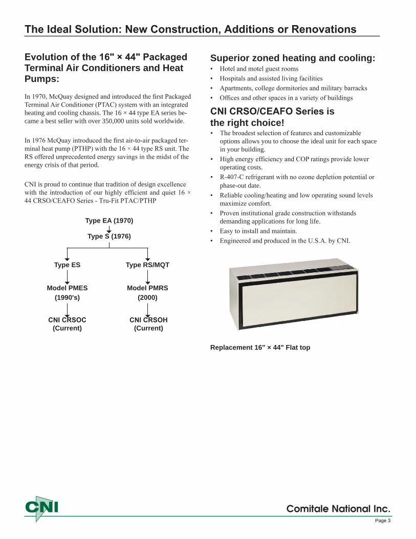
In 1970, McQuay designed and introduced the first Packaged Terminal Air Conditioner (PTAC) system with an integrated heating and cooling chassis. The 16 × 44 type EA series be-came a best seller with over 350,000 units sold worldwide.
In 1976 McQuay introduced the first air-to-air packaged ter-minal heat pump (PTHP) with the 16 × 44 type RS unit. The RS offered unprecedented energy savings in the midst of the energy crisis of that period.
CNI is proud to continue that tradition of design excellence with the introduction of our highly efficient and quiet 16 × 44 CRSO/CEAFO Series - Tru-Fit PTAC/PTHP
Type EA (1970)
Type S (1976)
Type ES Type RS/MQT
Model PMES Model PMRS(1990's) (2000)
CNI CRSOC (Current)
CNI CRSOH (Current)
Superior zoned heating and cooling:• Hotel and motel guest rooms• Hospitals and assisted living facilities• Apartments, college dormitories and military barracks• Offices and other spaces in a variety of buildings
CNI CRSO/CEAFO Series is the right choice!• The broadest selection of features and customizable
options allows you to choose the ideal unit for each spacein your building.
• High energy efficiency and COP ratings provide loweroperating costs.
• R-407-C refrigerant with no ozone depletion potential orphase-out date.
• Reliable cooling/heating and low operating sound levelsmaximize comfort.
• Proven institutional grade construction withstandsdemanding applications for long life.
• Easy to install and maintain.• Engineered and produced in the U.S.A. by CNI.
Replacement 16" × 44" Flat top
Comitale National Inc.Page 3
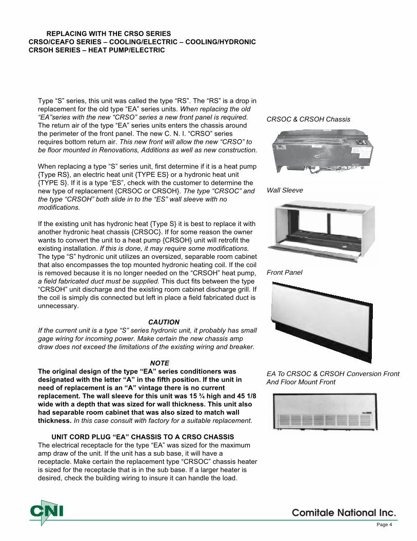
CRSOC & CRSOH Chassis
Wall Sleeve
Front Panel
EA To CRSOC & CRSOH Conversion FrontAnd Floor Mount Front
REPLACING WITH THE CRSO SERIES CRSO/CEAFO SERIES – COOLING/ELECTRIC – COOLING/HYDRONICCRSOH SERIES – HEAT PUMP/ELECTRIC
Type “S” series, this unit was called the type “RS”. The “RS” is a drop in replacement for the old type “EA” series units. When replacing the old “EA”series with the new “CRSO” series a new front panel is required. The return air of the type “EA” series units enters the chassis around the perimeter of the front panel. The new C. N. I. “CRSO” series requires bottom return air. This new front will allow the new “CRSO” to be floor mounted in Renovations, Additions as well as new construction.
When replacing a type “S” series unit, first determine if it is a heat pump {Type RS}, an electric heat unit {TYPE ES} or a hydronic heat unit {TYPE S}. If it is a type “ES”, check with the customer to determine the new type of replacement {CRSOC or CRSOH}. The type “CRSOC” and the type “CRSOH” both slide in to the “ES” wall sleeve with no modifications.
If the existing unit has hydronic heat {Type S} it is best to replace it with another hydronic heat chassis {CRSOC}. If for some reason the owner wants to convert the unit to a heat pump {CRSOH} unit will retrofit the existing installation. If this is done, it may require some modifications. The type “S” hydronic unit utilizes an oversized, separable room cabinet that also encompasses the top mounted hydronic heating coil. If the coil is removed because it is no longer needed on the “CRSOH” heat pump, a field fabricated duct must be supplied. This duct fits between the type “CRSOH” unit discharge and the existing room cabinet discharge grill. If the coil is simply dis connected but left in place a field fabricated duct is unnecessary.
CAUTIONIf the current unit is a type “S” series hydronic unit, it probably has small gage wiring for incoming power. Make certain the new chassis amp draw does not exceed the limitations of the existing wiring and breaker.
NOTEThe original design of the type “EA” series conditioners was designated with the letter “A” in the fifth position. If the unit in need of replacement is an “A” vintage there is no current replacement. The wall sleeve for this unit was 15 ¾ high and 45 1/8 wide with a depth that was sized for wall thickness. This unit also had separable room cabinet that was also sized to match wall thickness. In this case consult with factory for a suitable replacement.
UNIT CORD PLUG “EA” CHASSIS TO A CRSO CHASSISThe electrical receptacle for the type “EA” was sized for the maximum amp draw of the unit. If the unit has a sub base, it will have a receptacle. Make certain the replacement type “CRSOC” chassis heater is sized for the receptacle that is in the sub base. If a larger heater is desired, check the building wiring to insure it can handle the load.
Comitale National Inc.Page 4

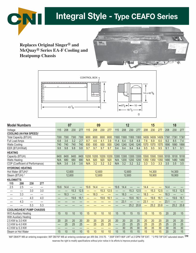
Model Numbers 07 09 12 15 18Voltage 115 208 230 277 115 208 230 277 115 208 230 277 208 230 277 208 230 277COOLING (HI-FAN SPEED)1
Total Capacity (BTUH) 7300 7300 7300 7300 9000 9000 9000 9000 11800 11800 11800 11800 14939 14939 14939 17361 17361 17361Full Load Amps 6.8 3.6 3.2 2.7 8.7 4.6 4.1 3.9 11.4 6.4 5.8 4.8 7.6 6.9 6.0 9.2 8.5 7.4Watts Cooling 740 740 740 740 930 930 930 930 1240 1240 1240 1240 1570 1570 1570 1890 1890 1890EER (BTUH/Watt) 9.8 9.8 9.8 9.8 9.7 9.7 9.7 9.7 9.4 9.4 9.4 9.4 9.5 9.5 9.5 9.1 9.1 9.1HEATINGCapacity (BTUH) 8400 8400 8400 8400 10200 10200 10200 10200 13300 13300 13300 13300 15500 15500 15500 18100 18100 18100Watts Heating N/A 680 680 680 N/A 920 920 920 N/A 1200 1200 1200 1350 1350 1350 1480 1480 1480COP (Coefficient of Performance) N/A 3.6 3.6 3.6 N/A 3.2 3.2 3.2 N/A 3.2 3.2 3.2 3.3 3.3 3.3 3.5 3.5 3.5HYDRONIC HEATINGHot Water (BTUH)2 12,600 12,600 12,600 14,300 14,300Steam (BTUH) 3 12,600 12,600 12,600 18,900 18,900KILOWATTS
115 208 230 2772.5 2.5 — — 19.6 14.4 — — 19.6 14.4 — — 19.6 14.4 — — 14.4 — — 14.4 — —— — 3.0 3.0 — — 15.3 12.5 — — 15.3 12.5 — — 15.3 12.5 — 15.3 12.5 — 15.3 12.5— 3.3 — — — 18.3 — — — 18.3 — — — 18.3 — — 18.3 — — 18.3 — —— — 4.0 4.0 — — 19.6 16.1 — — 19.6 16.1 — — 19.6 16.1 — 19.6 16.1 — 19.6 16.1— 4.3 — — — — — — — — — — — 23.1 — — 23.1 — — 23.1 — —— — 5.3 5.3 — — — — — — — — — — 25.2 20.8 — 25.2 20.8 — 25.2 20.8
COOLING/HEAT PUMP CHASSISW/O Auxiliary Heating 15 10 10 10 15 10 10 10 15 15 15 15 15 15 15 20 20 15With Auxiliary Heating2.5 KW to 3.0 KW 20 20 20 20 20 20 20 20 20 20 20 20 20 20 20 20 20 203.3 KW to 4.0 KW — 25 25 25 — 25 25 25 — 25 25 25 25 25 25 25 25 254.3 KW to 5.3 KW — — — — — — — — — 30 35 30 30 35 30 30 35 30Steam or Hot Water 15 10 10 10 15 10 10 10 15 15 15 15 15 15 15 20 20 15
NEMA 5-15R (115V)
Service: 15 AmpVoltage: 115V
2 MOTOR APPLICATION REPLACEMENT PACKAGED TERMINAL AIR CONDITIONERSReplaces Original Singer® and McQuay® Type EA-RS (S, ES, MEA, MQA,MQT, PMES, PDAC and PDHP) and
PMES Cooling and Heatpump Chassis.
43 7/8
CONTROL BOX
1514 x 42 5/8
18 1/2
81/2 1043 7/8
CONTROL BOX
1514 x 42 5/8
18 1/2
81/2 10
COMITALE NATIONAL, INC. 1683 B Winchester Road • Bensalem, PA 19020215- 244-9650 • FAX 215-244-9679 • www.comitalenational.com • email: [email protected]
Original Equipment Manufacturer of Custom PTAC/PTHP Thru the Wall units.
NEMA 6-15R (250V)
Service: 15 AmpVoltage: 208/230V
NEMA 7-20R (277V)
Service: 20 AmpVoltage: 277V
NEMA 6-20R (250V)
Service: 20 AmpVoltage: 208/230V
NEMA 6-30R (250V)
Service: 30 AmpVoltage: 208/230V
W
NEMA 5-20R (115V)
Service: 20 AmpVoltage: 115V
139-0100 139-0011 139-0101 139-0018 139-0010 139-0012
NEMA RECEPTACLES
Note: Many other Singer® McQuay® Replacement chassis are also available.
INTEGRAL STYLE TYPE CRSO SERIESSINGER® MCQUAY® EA-RS FULL SIZE REPLACEMENT CHASSIS
THE CNI TRU-FIT®
replacement PTAC Type EA-RS heating and coolingchassis is a one piece completeunit designed to install in oneeasy step. No tools, baffles, orother assemblies are needed. Justsimply slide your old Singer®
McQuay® EA-RS unit out and slidethe new CNI, 7-18,000 BTUH Tru-Fit unit in.
Integral Style - A complete, self-contained chassis consisting of condensor motor assembly, evaporator motor, board assembly, along with a control box.
Front View Side View
Integral Style - Type CRSO Series
Replaces Original Singer® and McQuay® Type EA-RS (S, ES, MEA, MQA,MQT, PMES, PDAC and PDHP) andPMES Cooling and Heatpump Chassis.
180F DB/67F WB air entering evaporator; 95F DB/75F WB air entering condenser per ARI Std. 310-70. 2 200F EWT/180F LWT at 2 GPM 70F EAT. 3 2 PSI 70F EAT saturated steam. CNI reserves the right to modify specifications without prior notice in its efforts to improve product quality.
Model Numbers 07 09 12 15 18Voltage 115 208 230 277 115 208 230 277 115 208 230 277 208 230 277 208 230 277COOLING (HI-FAN SPEED)1
Total Capacity (BTUH) 7300 7300 7300 7300 9000 9000 9000 9000 11800 11800 11800 11800 14939 14939 14939 17361 17361 17361Full Load Amps 6.8 3.6 3.2 2.7 8.7 4.6 4.1 3.9 11.4 6.4 5.8 4.8 7.6 6.9 6.0 9.2 8.5 7.4Watts Cooling 740 740 740 740 930 930 930 930 1240 1240 1240 1240 1570 1570 1570 1890 1890 1890EER (BTUH/Watt) 9.8 9.8 9.8 9.8 9.7 9.7 9.7 9.7 9.4 9.4 9.4 9.4 9.5 9.5 9.5 9.1 9.1 9.1HEATINGCapacity (BTUH) 8400 8400 8400 8400 10200 10200 10200 10200 13300 13300 13300 13300 15500 15500 15500 18100 18100 18100Watts Heating N/A 680 680 680 N/A 920 920 920 N/A 1200 1200 1200 1350 1350 1350 1480 1480 1480COP (Coefficient of Performance) N/A 3.6 3.6 3.6 N/A 3.2 3.2 3.2 N/A 3.2 3.2 3.2 3.3 3.3 3.3 3.5 3.5 3.5HYDRONIC HEATINGHot Water (BTUH)2 12,600 12,600 12,600 14,300 14,300Steam (BTUH) 3 12,600 12,600 12,600 18,900 18,900KILOWATTS
115 208 230 2772.5 2.5 — — 19.6 14.4 — — 19.6 14.4 — — 19.6 14.4 — — 14.4 — — 14.4 — —— — 3.0 3.0 — — 15.3 12.5 — — 15.3 12.5 — — 15.3 12.5 — 15.3 12.5 — 15.3 12.5— 3.3 — — — 18.3 — — — 18.3 — — — 18.3 — — 18.3 — — 18.3 — —— — 4.0 4.0 — — 19.6 16.1 — — 19.6 16.1 — — 19.6 16.1 — 19.6 16.1 — 19.6 16.1— 4.3 — — — — — — — — — — — 23.1 — — 23.1 — — 23.1 — —— — 5.3 5.3 — — — — — — — — — — 25.2 20.8 — 25.2 20.8 — 25.2 20.8
COOLING/HEAT PUMP CHASSISW/O Auxiliary Heating 15 10 10 10 15 10 10 10 15 15 15 15 15 15 15 20 20 15With Auxiliary Heating2.5 KW to 3.0 KW 20 20 20 20 20 20 20 20 20 20 20 20 20 20 20 20 20 203.3 KW to 4.0 KW — 25 25 25 — 25 25 25 — 25 25 25 25 25 25 25 25 254.3 KW to 5.3 KW — — — — — — — — — 30 35 30 30 35 30 30 35 30Steam or Hot Water 15 10 10 10 15 10 10 10 15 15 15 15 15 15 15 20 20 15
TYPE CEAF0 SERIESReplacement Packaged Terminal Air Conditioners
Replaces Original Singer® and McQuay® Series EA-F Cooling and Heatpump Chassis
43 7/8
CONTROL BOX
15 14 x 42 5/8
18 1/2
81/2 10
�
Comitale National, Inc.1683 B Winchester Road • Bensalem, PA 19020 • 215- 244-9650 • FAX 215-244-9679
Visit our website - www.comitalenational.com • email: [email protected]
NEMA Receptacles — Mating Power Receptacles for CNI Integral Style Units
NEMA 5-15R(115V)
Service: 15 AmpVoltage: 115V
Integral StyleA complete, self-contained chassis consisting of
motor assembly, heating and cooling system, along with a control box.
NEMA 6-15R(250V)
Service: 15 AmpVoltage: 208/230V
NEMA 5-20R(115V)
Service: 20 AmpVoltage: 115V
NEMA 6-20R(250V)
Service: 20 AmpVoltage: 208/230V
NEMA 6-30R(250V)
Service: 30 AmpVoltage: 208/230V
NEMA 7-20R(277V)
Service: 20 AmpVoltage: 277V
W
139-0100 139-0011 139-0101 139-0018 139-0010 139-0012
A lower cost alternative to all season comfort conditioning.• More Reliability • Less Maintenance • Simpler Installation
• Higher Efficiency • A Quieter Solution • A Tru-FitQuality and Comfort for many years to come!!
Call CNI for more details and competitive pricing!Ask about our Quick Shipment Program.
Think CNI for all of your replacement HVAC parts needs.
CNIIntegral Style - Type CEAFO Series
Replaces Original Singer® and McQuay® Series EA-F Cooling and Heatpump Chassis
180F DB/67F WB air entering evaporator; 95F DB/75F WB air entering condenser per ARI Std. 310-70. 2 200F EWT/180F LWT at 2 GPM 70F EAT. 3 2 PSI 70F EAT saturated steam. CNI
reserves the right to modify specifications without prior notice in its efforts to improve product quality.

CRSO/CEAFO Series Engineering/Specifications
COOLING CHASSIS – The cooling chassis shall contain the complete refrigeration system consisting of compressor, condenser, evaporator and separate fan motors for the condenser and evaporator sections; as well as the controls. A space for inclusion of electric heating elements. It shall be 100% factory run tested prior to shipment from the factory. The chassis sheet metal shall be a minimum of 18 gauge G-90 grade galvanized, zinc phosphatized steel. The chassis base pan shall be a minimum of 16 gauge galvanized steel. The evaporator and condenser coil construction shall be copper tubes with aluminum ripple fans and mounted for accessible cleaning. Condensate disposal shall be accomplished by atomization and entrainment of water particles in the condenser air stream with evaporation on the condenser coil. Slinger rings and propeller type are not acceptable.
The refrigeration circuit shall be precharged and shall utilize a rotary compressor, PSC motors with automatic reset overload. Compressor shall be equipped with suction and discharge mufflers. Compressor capacitor shall be located in control box only. Refrigerant metering shall be accomplished by automatic expansion valve. Capillary tubes are not acceptable. The unit shall operate at capacity to 35°F outdoor, with no frosting of the evaporator, short cycling of the compressor or liquid slugging. A hot gas bypass valve shall be used to protect the evaporator coil from frosting due to clogged filter, or low air flow.
Factory installed sheathed electric heating coils shall be mounted in the outlet air stream of the evaporator fan and ahead of the evaporator coil. Automatic reset thermal cut-off shall protect the element from overheating. Heat requirement of 4 KW or more shall be two staged to operate with the thermostat.
Two row serpentine coil, preformed tubing and normally opened motorized two-position control valve shall be provided for field installation and piping to hot water or steam service. Right hand supply/return connections. Control valve shall be two-way type and power lead shall plug into the control box.
Airflow system shall include separate fan motors for the condenser and evaporator sections. The condenser fan motor shall be a single speed totally enclosed, permanently lubricated fan motor. The condenser fan wheel shall be aluminum formed single inlet centrifugal type. Plastic or polymer are not acceptable. The indoor fan motor shall be a double shafted, two-speed, totally enclosed; permanently lubricated fan motor must be position on the indoor side of the bulkhead so as to be completely within the conditioned filtered airstream. The indoor blower fan shall be forward-curved tangential design to provide even airflow across the evaporator coil.
ROOM CABINET/WALL SLEEVE/FRONT PANEL – TThe wall cabinet which houses the cooling chassis shall be of 18 gauge phosphatized steel and finished with two coats of baked textured acrylic enamal. The wall cabinet shall also be insulated top and sides, with a closed cell neoprene rubber insulation. The wall cabinet shall be designed for either wall installation or flush floor installation, without a regard for unit voltage, with the exception of 265V Chassis. The wall cabinet is provided with extruded aluminum louver finished in a clear anodized. Room cabinet/wall sleeve and front panel color is light beige. Special colors are available, consult factory.
Installed height of the room cabinet/wall sleeve shall not exceed 16 3/8 {416mm}. Installed height of room cabinet/wall sleeve with subbase shall not exceed 20 3/8 {518mm} for electric heat or 24 3/8 {619mm} for hydronic heat. The discharge grill assembly and access door are part of the room cabinet/wall sleeve design. The discharge grill can be stamped or drop in heavy gauge aluminum discharge grill. The discharge is noted both for its strength and appearance. The grill is inclined at a fixed angle of 15° from vertical to provide optimum air circulation.
Front Panel and Return Air Option - "CRSO/CEAFO" series can use 2 different types of front panels. The standard front panel is a solid front panel. The second type of front panel incorporates a stamped return air grill this is used when replacing an original McQuay or Singer type "EA" with the C. N. I "CRSO/CEAFO" series. This particular front panel will also allow the C. N. I. "CRSO/CEAFO" series unit to be floor mounted.
SUBBASES - The "CRSO/CEAFO" series unit utilizes two different subbases. The electrical subbase requires a minimum of 4 3/8 from the front edge of the wall sleeve to the finish wall. The hydronic subbase requires 1" minimum from the front edge of the wall sleeve to the finished wall.
CNI reserves the right to modify specifications without prior notice in its efforts to improve product quaility.
Page 7
Comitale National Inc.
OPTIONAL – The cooling/heating chassis can be equipped for a pressurized automatic ventilation air. An outdoor damper can be positioned on the discharge side of the condenser fan to insure a positive supply of ventilation air whenever called for. The damper must close when the unit stops. Outdoor air shall be filtered at all times.
CONTROLS – The standard controls shall be self contained within the cooling chassis consisting of a manual Idle-Cool-Heat-Hi-Low selection along with a two stage thermostat. Automatic Ventilation can be controlled by a means of a rocker switch at the control panel. Optional control arrangements are available, consult factory.

Comitale National Inc.
Product Code
Chassis TypeH = Heatpump
C = Cooling only
07 - 7000 BTUH 09 - 9000 BTUH
12 - 12000 BTUH 15 - 15000 BTUH 18 - 18000 BTUH
Electrical Service3 = 115/60/1
4 = 208/230/60/15 = 277/60/1
Design Sequence RS = Rotary CompressorAS = Reciprocating CompressorAZ = Special
Control Options0 = None1 = Night Set Back2 = Remote Switching with
Night Setback3= Fan Cycle Switch (Heating Mode)4= Auxiliary - Permanent Power*Voltage needs to be determined forprimary (Hydronic Heat Only)Z = Consult Factory
Thermostat Nominal Size 0 = Cooling only, Component Style Chassis1 = Unit Mounted Manual Changeover2 = Wall Mounted, Manual Changeover*3 = Unit Mounted Automatic Changeover*4 = Wall Mounted, Automatic Changeover5 = Non-Programmable Wireless Wall Mounted6 = Programmable Wireless Wall Mounted*Not available on HP chassisK
Heat Source0 = Cooling onlyD = Hydronic HeatA = 2.5/3.0 KWB = 3.3/4.0 KW*C = 4.3/5.3 KW*Not available sizes 07 and 09
Z = SpecialsOutlined in Spec.
Product Code Sheet (Z in any box = Special)
CRSO C 09 4 - D 1 0 RS
Page 8
Nominal Size
The Sample unit nomenclature above indicates a C.N.I. colling chassis replacement for Singer and McQuay "RS, MQT, PMES, PMRS" Series, 9,000 BTUH, 208-230/60/1, Hydronic heat, unit mounted manual change over controls and no control options.
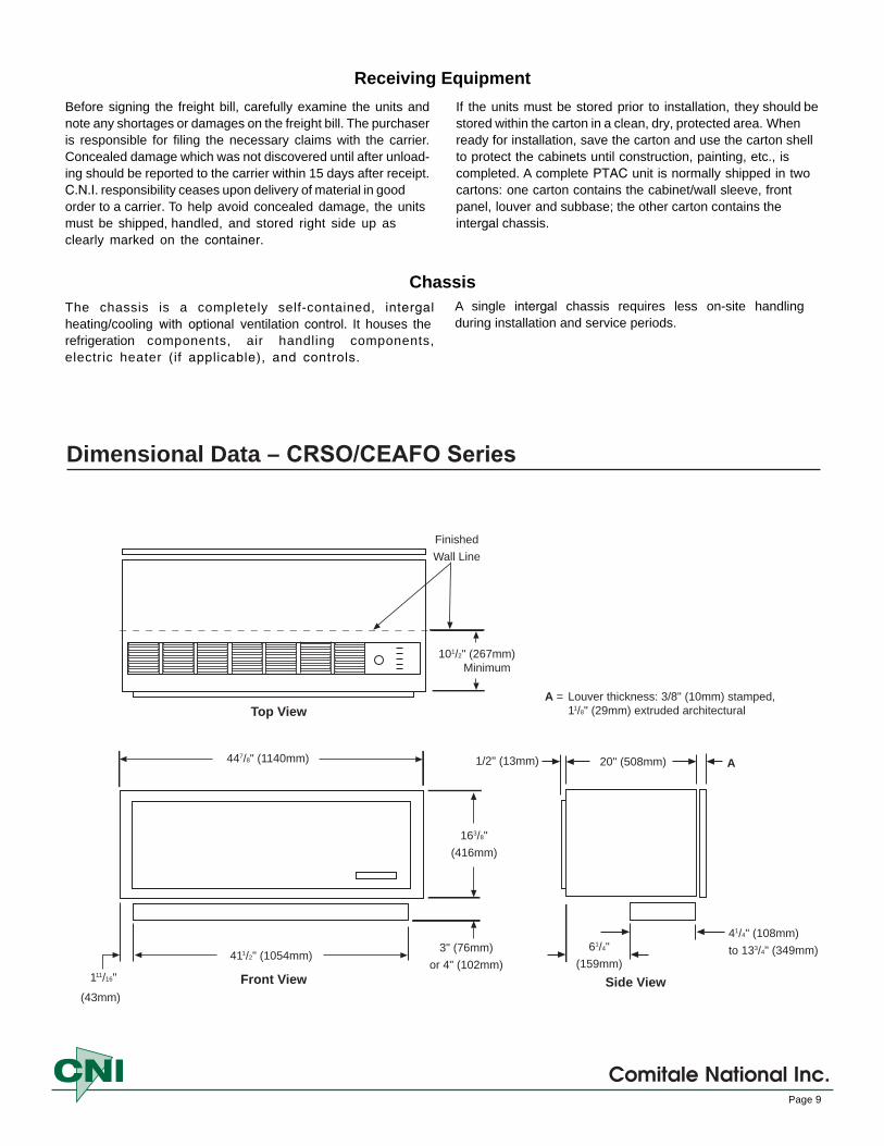
Dimensional Data – CRSO/CEAFO Series
163/8" (416mm)
447/8" (1140mm)
411/2" (1054mm)
111/16"
(43mm)
3" (76mm)or 4" (102mm)
101/2" (267mm) Minimum
Finished Wall Line
61/4" (159mm)
41/4" (108mm) to 133/4" (349mm)
20" (508mm) 1/2" (13mm) A
A = Louver thickness: 3/8" (10mm) stamped, 11/8" (29mm) extruded architecturalTop View
Front View Side View
Comitale National Inc.Page 9
Before signing the freight bill, carefully examine the units and note any shortages or damages on the freight bill. The purchaser is responsible for filing the necessary claims with the carrier. Concealed damage which was not discovered until after unload-ing should be reported to the carrier within 15 days after receipt. C.N.I. responsibility ceases upon delivery of material in goodorder to a carrier. To help avoid concealed damage, the unitsmust be shipped, handled, and stored right side up asclearly marked on the container.
If the units must be stored prior to installation, they should be stored within the carton in a clean, dry, protected area. When ready for installation, save the carton and use the carton shell to protect the cabinets until construction, painting, etc., is completed. A complete PTAC unit is normally shipped in two cartons: one carton contains the cabinet/wall sleeve, front panel, louver and subbase; the other carton contains the intergal chassis.
Receiving Equipment
The chassis is a completely self-contained, intergal heating/cooling with optional ventilation control. It houses the refrigeration components, air handling components, electric heater (if applicable), and controls.
A single intergal chassis requires less on-site handling during installation and service periods.
Chassis
Installation – ConsiderationsThe CRSO/CEAFO Series 16" x 44" Unit is
designed and built for through-the-wall installation in either existing or new buildings. Each conditioner consists of the following components identified in their typical installation sequence:1. Subbase – Optional on 208/230V, standard on 265V,
shipped in its own carton.2. Louver Frame – Optional, shipped five (5) per
carton.3. Room Cabinet/Wall Sleeve with Front Panel and
Filter – Shipped in palletized carton.4. Outdoor Louver – Shipped in its own carton.
IMPORTANTAir flow required for PTAC units must not be restricted by exterior plants or walls. Plants or shrubs must not be planted in close proximity to the outside grille of the PTAC unit. Vegetation planted too close to grilles will cause discharge air to be recirculated, thereby increasing electrical consumption. Warranty will be voided if it is determined that the compressor life is shortened from overheating due to close proximity of outside obstructions.
Note: Discharge air restrictions include, but are not limited to:
• Vegetation• Concrete walls or barriers• Overhangs that do not allow discharge air to rise• Installation of bug screen of any kind
5. Heating/Cooling Chassis – Shipped in palletizedcarton.
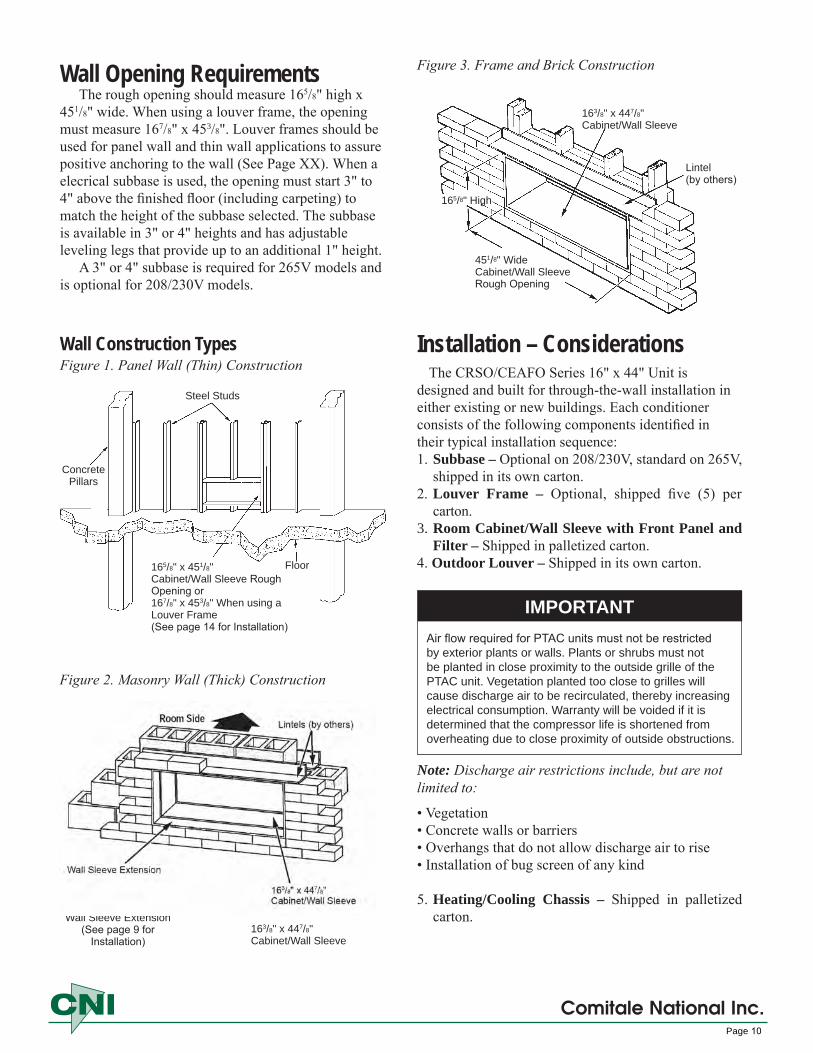
Figure 3. Frame and Brick Construction
Figure 2. Masonry Wall (Thick) Construction
165/8" x �51/8" Cabinet/Wall Sleeve Rough Opening or 167/8" x �53/8" When using a Louver Frame(See page 14 for Installation)
Floor
Concrete Pillars
Steel Studs
163/8" x ��7/8" Cabinet/Wall Sleeve
Lintel (by others)
�51/8" Wide Cabinet/Wall Sleeve Rough Opening
165/8" High
Wall Opening RequirementsThe rough opening should measure 165/8" high x
451/8" wide. When using a louver frame, the opening must measure 167/8" x 453/8". Louver frames should be used for panel wall and thin wall applications to assure positive anchoring to the wall (See Page XX). When a elecrical subbase is used, the opening must start 3" to 4" above the finished floor (including carpeting) to match the height of the subbase selected. The subbase is available in 3" or 4" heights and has adjustable leveling legs that provide up to an additional 1" height.
A 3" or 4" subbase is required for 265V models and is optional for 208/230V models.
Wall Construction TypesFigure 1. Panel Wall (Thin) Construction
Wall Sleeve Extension(See page 9 for
Installation)163/8" x ��7/8"Cabinet/Wall Sleeve
Comitale National Inc.Page 10

Masonry and Thick Wall Applications1.
2.
3.
Preparation of the wall opening — In new construc-tion, the room cabinet/wall sleeve can be built into the building wall as it progresses, or openings can be left for later installation.A lintel by others must be used to support any brick or masonry work above the conditioner.Set the room cabinet/wall sleeve in soft mortar and position it in the wall opening. The rear face of the conditioner should be recessed from the outside edge of the wall opening by the depth of the louver to be installed. When using the flanged stamped louver, the rear flange of the room cabinet/wall sleeve will be flush with outside edge of the wall opening. The center of gravity of the conditioner is 91⁄2" from the rear face. For wall-mounted condi-tioners, the center of gravity must be within the load bearing portion of the wall; otherwise, sup-port is required.Level the room cabinet/wall sleeve side to side and pitch down 1/4 bubble to outside. Securely fas-ten the room cabinet/wall sleeve in the wall from inside the cabinet through the sides and/or top on the outdoor side of the weather seal. Make sure the cabinet is not distorted. Never secure through the bottom of the cabinet. For installations using a subbase, level the room cabinet/wall sleeve with leveling bolts provided with the subbase. Attach the subbase to the room cabinet/wall sleeve per instructions provided with the subbase. Refer to Page 19
4. After the room cabinet/wall sleeve is installed andleveled side to side and pitched down 1/4 bubble tothe outside, secure it and the louver frame to thewall with screws driven through the sides and topof the room cabinet/wall sleeve outward through thelouver frame. Never secure the frame through thebottom, as it may cause leaks. A 5⁄32" diameter holehas been added to each side of the wall sleeve as aprovision for securing the sleeve in the wallopening. Each hole is located 2" down from the topand 2" in from the rear of the sleeve. (See Figures 4and 3.) These holes or other non-perforated locations in thesides and/or top of the sleeve may be used to fastenthe sleeve to the wall from the inside. Never securethe room cabinet/wall sleeve to the wall through thebottom.
5. Caulk the outdoor joint between the room cabinet/wall sleeve and the wall opening (or louver frame):top, bottom and both sides. Do not permit caulkingto block the weep holes.
6. Install the outdoor louver. Holding the louverwith a wire loop, or other similar means, push thelouver out through the rear opening in the roomcabinet/wall sleeve and pull the louver back tothe rear face so that the louver studs pass throughthe holes in the room cabinet/wall sleeve flange.Attach the louver with the washers and nuts, andsecurely tighten the louver in place.
7. Cut the shipping carton as necessary to cover theinstalled room cabinet/wall sleeve until ready foruse.
5⁄32" Dia. (typical of 2)
Subbase
2"
2"Figure 5.
Lintel by others
Louver Depth
Mortar Base
Outside wall
Note: Subbase is optional on 208/230V units, but standard on 265V.Louver frame is optional on all units.
Outside wall
33⁄8" (86mm)
Louver Depth
Room cabinet/wall sleeve
Finished Wall
Louver Frame
Finished Wall
Finished Floor
Optional Subbase
5⁄32" Dia. (typical of 2)
Figure 4.
Finished Floor
Comitale National Inc.Page 11
Electric Service – All wiring should be done in accor-dance with local and national electrical codes. Electric service for the CRSO/CEAFO unit is via a receptacle type outlet furnished with 265V units. 208/230V units are equipped with a plug and cord set to plug into a recep-tacle which is supplied by others and field installed.
The use of an extension cord to increase the length of the plug/cord set furnished as a part of the unit is not recommended.
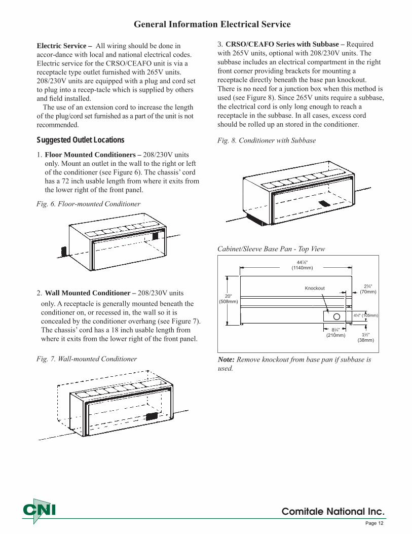
Suggested Outlet Locations
1. Floor Mounted Conditioners – 208/230V unitsonly. Mount an outlet in the wall to the right or leftof the conditioner (see Figure 6). The chassis’ cordhas a 72 inch usable length from where it exits fromthe lower right of the front panel.
2. Wall Mounted Conditioner – 208/230V unitsonly. A receptacle is generally mounted beneath theconditioner on, or recessed in, the wall so it isconcealed by the conditioner overhang (see Figure 7).The chassis’ cord has a 18 inch usable length fromwhere it exits from the lower right of the front panel.
��7⁄8"(1140mm)
20"(508mm)
23⁄�"(70mm)
�1⁄8" (105mm)
81⁄�"(210mm)
Cabinet/Sleeve Base Pan - Top View
Note: Remove knockout from base pan if subbase is used.
11⁄2"(38mm)
Knockout
Fig. 6. Floor-mounted Conditioner
Fig. 7. Wall-mounted Conditioner
3. CRSO/CEAFO Series with Subbase – Required with 265V units, optional with 208/230V units. The subbase includes an electrical compartment in the right front corner providing brackets for mounting a receptacle directly beneath the base pan knockout. There is no need for a junction box when this method is used (see Figure 8). Since 265V units require a subbase, the electrical cord is only long enough to reach a receptacle in the subbase. In all cases, excess cord should be rolled up an stored in the conditioner.
Fig. 8. Conditioner with Subbase
Comitale National Inc.Page 12
General Information Electrical Service
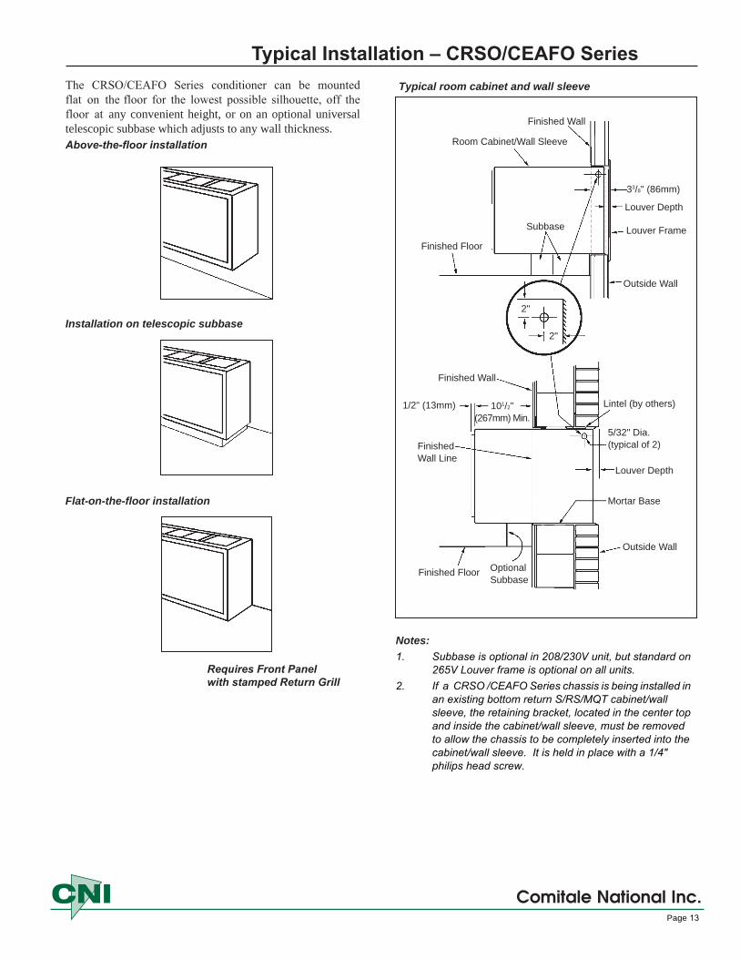
Typical Installation – CRSO/CEAFO SeriesThe CRSO/CEAFO Series conditioner can be mounted flat on the floor for the lowest possible silhouette, off the floor at any convenient height, or on an optional universal telescopic subbase which adjusts to any wall thickness.Above-the-floor installation
Installation on telescopic subbase
Flat-on-the-floor installation
Typical room cabinet and wall sleeve
Finished Wall Line
Outside Wall
Louver Depth
Mortar Base
Lintel (by others)
Finished Wall
Finished Floor OptionalSubbase
Room Cabinet/Wall Sleeve
Finished Wall
Outside Wall
2"
2"
101/2" (267mm) Min.
1/2" (13mm)
33/8" (86mm)
5/32" Dia. (typical of 2)
Louver Depth
Louver FrameFinished Floor
Subbase
Notes: 1. Subbase is optional in 208/230V unit, but standard on
265V Louver frame is optional on all units.2. If a CRSO /CEAFO Series chassis is being installed in
an existing bottom return S/RS/MQT cabinet/wall sleeve, the retaining bracket, located in the center top and inside the cabinet/wall sleeve, must be removed to allow the chassis to be completely inserted into the cabinet/wall sleeve. It is held in place with a 1/4" philips head screw.
Requires Front Panelwith stamped Return Grill
Comitale National Inc.Page 13
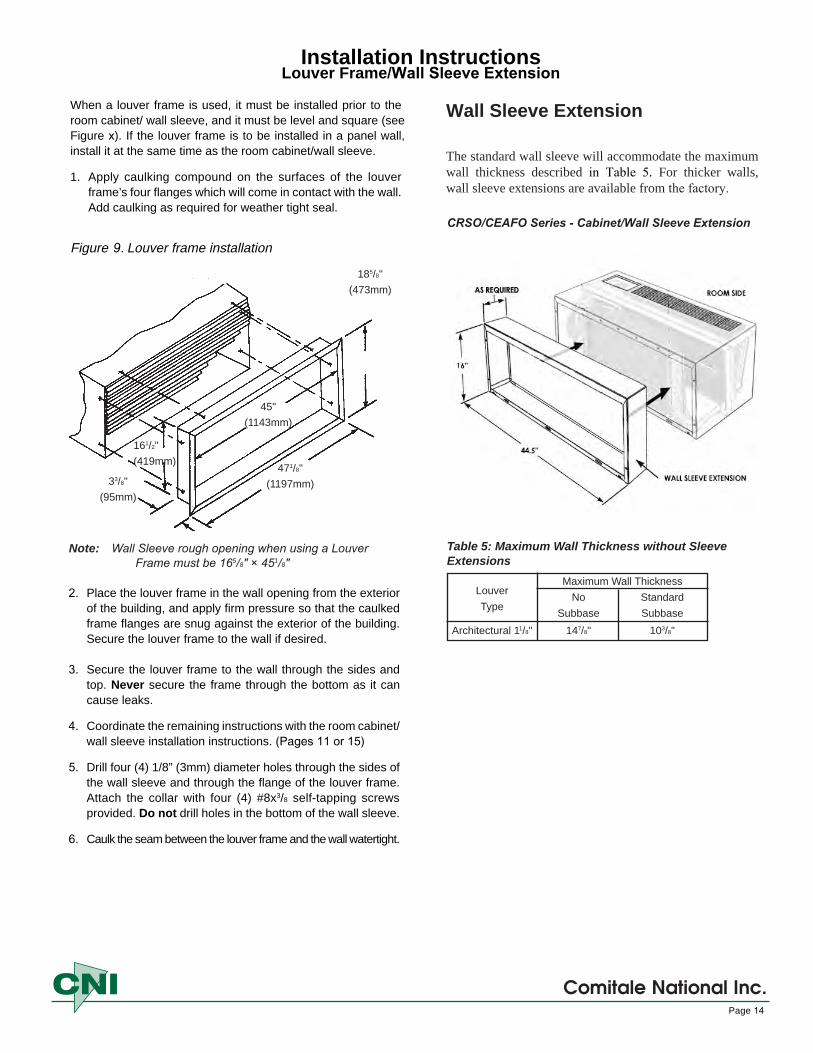
When a louver frame is used, it must be installed prior to the room cabinet/ wall sleeve, and it must be level and square (see Figure x). If the louver frame is to be installed in a panel wall, install it at the same time as the room cabinet/wall sleeve.
1. Apply caulking compound on the surfaces of the louverframe’s four flanges which will come in contact with the wall.Add caulking as required for weather tight seal.
2. Place the louver frame in the wall opening from the exteriorof the building, and apply firm pressure so that the caulkedframe flanges are snug against the exterior of the building.Secure the louver frame to the wall if desired.
3. Secure the louver frame to the wall through the sides andtop. Never secure the frame through the bottom as it cancause leaks.
4. Coordinate the remaining instructions with the room cabinet/wall sleeve installation instructions. (Pages 11 or 15)
5. Drill four (4) 1/8” (3mm) diameter holes through the sides ofthe wall sleeve and through the flange of the louver frame.Attach the collar with four (4) #8x3/8 self-tapping screwsprovided. Do not drill holes in the bottom of the wall sleeve.
6. Caulk the seam between the louver frame and the wall watertight.
Figure 9. Louver frame installation
Installation Instructions Louver Frame/Wall Sleeve Extension
45"(1143mm)
161/2"(419mm)
33/8"(95mm)
471/8"(1197mm)
185/8"(473mm)
Note: Wall Sleeve rough opening when using a Louver Frame must be 165/8" × 451/8"
Comitale National Inc.Page 14
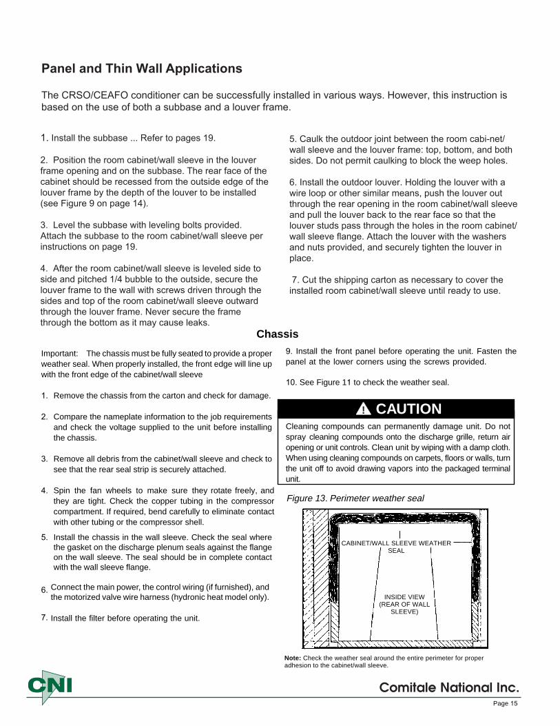
Wall Sleeve Extension
The standard wall sleeve will accommodate the maximum wall thickness described in Table 5. For thicker walls, wall sleeve extensions are available from the factory.
CRSO/CEAFO Series - Cabinet/Wall Sleeve Extension
Table 5: Maximum Wall Thickness without Sleeve Extensions
Maximum Wall ThicknessLouver No StandardType Subbase Subbase
Architectural 11/8" 147/8" 103/8"
Panel and Thin Wall Applications
The CRSO/CEAFO conditioner can be successfully installed in various ways. However, this instruction is based on the use of both a subbase and a louver frame.
1. Install the subbase ... Refer to pages 19.
2. Position the room cabinet/wall sleeve in the louverframe opening and on the subbase. The rear face of thecabinet should be recessed from the outside edge of thelouver frame by the depth of the louver to be installed(see Figure 9 on page 14).
3. Level the subbase with leveling bolts provided.Attach the subbase to the room cabinet/wall sleeve perinstructions on page 19.
4. After the room cabinet/wall sleeve is leveled side toside and pitched 1/4 bubble to the outside, secure thelouver frame to the wall with screws driven through thesides and top of the room cabinet/wall sleeve outwardthrough the louver frame. Never secure the framethrough the bottom as it may cause leaks.
Comitale National Inc.Page 15
5. Caulk the outdoor joint between the room cabi-net/wall sleeve and the louver frame: top, bottom, and bothsides. Do not permit caulking to block the weep holes.
6. Install the outdoor louver. Holding the louver with awire loop or other similar means, push the louver outthrough the rear opening in the room cabinet/wall sleeveand pull the louver back to the rear face so that thelouver studs pass through the holes in the room cabinet/wall sleeve flange. Attach the louver with the washersand nuts provided, and securely tighten the louver inplace.
7. Cut the shipping carton as necessary to cover theinstalled room cabinet/wall sleeve until ready to use.
9. Install the front panel before operating the unit. Fasten thepanel at the lower corners using the screws provided.
10. See Figure 11 to check the weather seal.
Cleaning compounds can permanently damage unit. Do notspray cleaning compounds onto the discharge grille, return airopening or unit controls. Clean unit by wiping with a damp cloth.When using cleaning compounds on carpets, floors or walls, turnthe unit off to avoid drawing vapors into the packaged terminalunit.
Important: The chassis must be fully seated to provide a properweather seal. When properly installed, the front edge will line upwith the front edge of the cabinet/wall sleeve
1. Remove the chassis from the carton and check for damage.
2. Compare the nameplate information to the job requirementsand check the voltage supplied to the unit before installingthe chassis.
3. Remove all debris from the cabinet/wall sleeve and check tosee that the rear seal strip is securely attached.
4.
5.
6.
7.
Spin the fan wheels to make sure they rotate freely, andthey are tight. Check the copper tubing in the compressor compartment. If required, bend carefully to eliminate contactwith other tubing or the compressor shell.
Install the chassis in the wall sleeve. Check the seal wherethe gasket on the discharge plenum seals against the flangeon the wall sleeve. The seal should be in complete contactwith the wall sleeve flange.
Connect the main power, the control wiring (if furnished), andthe motorized valve wire harness (hydronic heat model only).
Install the filter before operating the unit.
Chassis
CAUTION
Figure 13. Perimeter weather seal
Note: Check the weather seal around the entire perimeter for properadhesion to the cabinet/wall sleeve.
!
CABINET/WALL SLEEVE WEATHERSEAL
INSIDE VIEW(REAR OF WALL
SLEEVE)
Louver – WeightArchitectural = 8 lbs. (3kg)Notes: 1. Optional architectural extruded aluminum.
2. Louver can be installed from inside the building.
NOTICEAirflow required for PTAC units must not be restricted by ex-terior plants or walls. Plants or shrubs must not be planted in close proximity to the outside grille of the PTAC unit. Vegetation planted too close to grilles will cause discharge air to be recircu-lated, thereby increasing electrical consumption. Warranty will be voided if it is determined that the compressor life is shortened from overheating due to close proximity of outside obstructions
Note: Discharge air restrictions include, but are not limited to:• Vegetation• Concrete walls or barriers• Overhangs that do not allow discharge air to rise• Installation of bug screen of any kind• Outdoor louvers by others unless approved by the factory
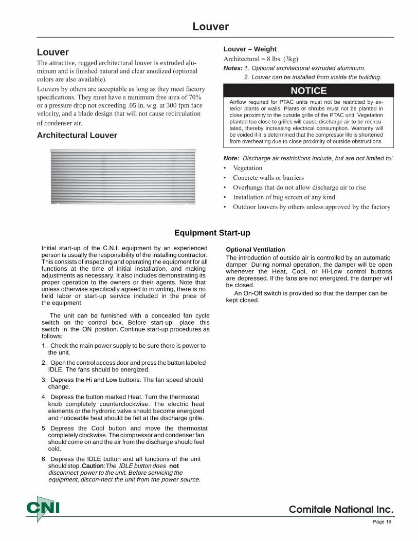
LouverThe attractive, rugged architectural louver is extruded alu-minum and is finished natural and clear anodized (optional colors are also available).Louvers by others are acceptable as long as they meet factory specifications. They must have a minimum free area of 70% or a pressure drop not exceeding .05 in. w.g. at 300 fpm face velocity, and a blade design that will not cause recirculation of condenser air.
Architectural Louver
Louver
Comitale National Inc.Page 16
Equipment Start-up
Initial start-up of the C.N.I. equipment by an experienced person is usually the responsibility of the installing contractor. This consists of inspecting and operating the equipment for all functions at the time of initial installation, and making adjustments as necessary. It also includes demonstrating its proper operation to the owners or their agents. Note that unless otherwise specifically agreed to in writing, there is no field labor or start-up service included in the price of the equipment.
The unit can be furnished with a concealed fan cycle switch on the control box. Before start-up, place this switch in the ON position. Continue start-up procedures as follows:
1. Check the main power supply to be sure there is power tothe unit.
2. Open the control access door and press the button labeledIDLE. The fans should be energized.
3. Depress the Hi and Low buttons. The fan speed should change.
4. Depress the button marked Heat. Turn the thermostatknob completely counterclockwise. The electric heatelements or the hydronic valve should become energizedand noticeable heat should be felt at the discharge grille.
5. Depress the Cool button and move the thermostatcompletely clockwise. The compressor and condenser fanshould come on and the air from the discharge should feelcold.
6. Depress the IDLE button and all functions of the unitshould stop. Caution: The IDLE button does notdisconnect power to the unit. Before servicing the equipment, discon-nect the unit from the power source.
Optional VentilationThe introduction of outside air is controlled by an automatic damper. During normal operation, the damper will be open whenever the Heat, Cool, or Hi-Low control buttons are depressed. If the fans are not energized, the damper will be closed.
An On-Off switch is provided so that the damper can be kept closed.

Hydronic subbase requires 1" minimum from the front edge of the wall sleeve to the finished wall.
Figure 11. Side �--------Channels ________ .._
Hydronic Heating
Coil
Permanent Mesh Filter
Louvered Front Panel
Coil Connection Cover Plate
Optional Fused Disconnect
Attach Capillary Tube Clip To This Screw
Assembling The Subbase Heat Section Subbase Side Channel Adjustment Telescoping side channels are supplied to extend from the finished wall to the rear of the subbase heat section. The side channels are reversible to enable adjustment without cutting or breaking.
Adjust the side channels as follows:1. Measure the distance between the finished wall and the
rear face of the subbase heat section.2. Insert the side channel into the slot of the subbase heat
section and telescope it the appropriate distance asmeasured in Step 1.
3. Slide the side channels into the sub base heat section andfasten securely with the screws provided.
4. Invert the subbase heat section and screw in the levelinglegs. The holes provided for the leveling legs are extrudedto eliminate the need for washers and nuts. The threads ofthe legs are self-tapping to assure a rigid fit.
5. Start the leveling leg into the extruded hole and apply awrench to the head. Turn the leg into the hole the desireddistance. Repeat this procedure until all the legs areinstalled.
6. Return the subbase heat section to the upright positionand center it under the wall opening.
Subbase Hydronic Heat Section
Comitale National Inc.Page 17
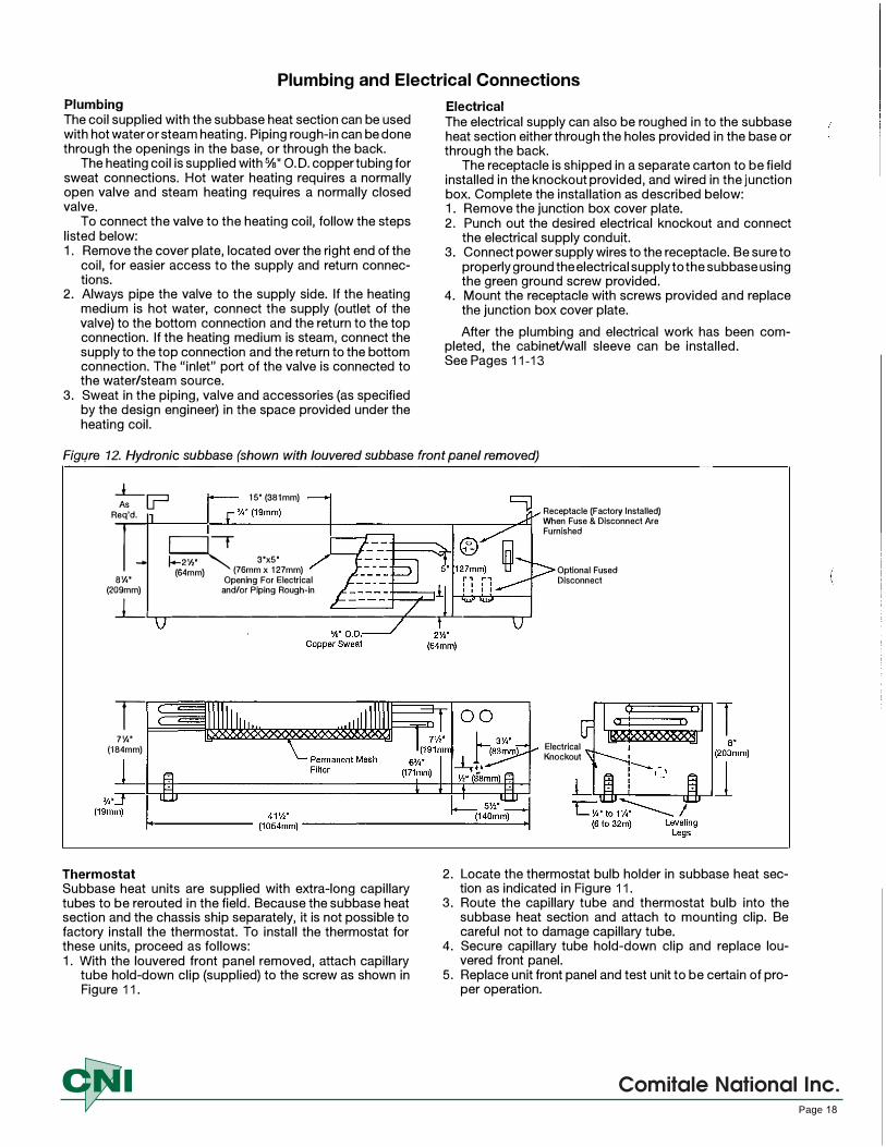
Plumbing and Electrical Connections
Plumbing The coil supplied with the subbase heat section can be used with hot water or steam heating. Piping rough-in can be done through the openings in the base, or through the back.
The heating coil is supplied with¾" O.D. copper tubing for sweat connections. Hot water heating requires a normally open valve and steam heating requires a normally closed valve.
To connect the valve to the heating coil, follow the steps listed below: 1. Remove the cover plate, located over the right end of the
coil, for easier access to the supply and return connections.
2. Always pipe the valve to the supply side. If the heatingmedium is hot water, connect the supply (outlet of thevalve) to the bottom connection and the return to the topconnection. If the heating medium is steam, connect thesupply to the top connection and the return to the bottomconnection. The "inlet" port of the valve is connected tothe water/steam source.
3. Sweat in the piping, valve and accessories (as specifiedby the design engineer) in the space provided under theheating coil.
Electrical
The electrical supply can also be roughed in to the subbase heat section either through the holes provided in the base or through the back.
The receptacle is shipped in a separate carton to be field installed in the knockout provided, and wired in the junction box. Complete the installation as described below: 1. Remove the junction box cover plate.2. Punch out the desired electrical knockout and connect
the electrical supply conduit.3. Connect power supply wires to the receptacle. Be sure to
properly ground the electrical supply to the subbase usingthe green ground screw provided.
4. Mount the receptacle with screws provided and replacethe junction box cover plate.
After the plumbing and electrical work has been completed, the cabineVwall sleeve can be installed. See Pages 11-13
Figwe 12. Hydronic subbase (shown with louvered subbase front panel removed)
_L_ As u==i 15" (381mm)
Req'd.
l7t r � 3"x5' (64mm) (76mm x 127mm)
a¼· (209mm)
Opening For Electrical and/or Piping Rough-in
Receptacle (Factory Installed) When Fuse & Disconnect Are Furnished
Optional Fused Disconnect
J_L.-.------------+--r1--'-----,,--,-1
I 7¼"
(184mm)
Thermostat Subbase heat units are supplied with extra-long capillary tubes to be rerouted in the field. Because the subbase heat section and the chassis ship separately, it is not possible to factory install the thermostat. To install the thermostat for these units, proceed as follows: 1. With the louvered front panel removed, attach capillary
tube hold-down clip (supplied) to the screw as shown in Figure 11.
Electrical Knockout
2. Locate the thermostat bulb holder in subbase heat section as indicated in Figure 11.
3. Route the capillary tube and thermostat bulb into the subbase heat section and attach to mounting clip. Be careful not to damage capillary tube.
4. Secure capillary tube hold-down clip and replace louvered front panel.
5. Replace unit front panel and test unit to be certain of proper operation.
Comitale National Inc.Page 18

Electrical Subbase InstallationAn electrical subbase is optional for all 208V and 230V units. The standard subbase is available with 3” (76 mm) or 4” (102 mm) heights. The subbase contains leveling legs for adjustment of up to 1” (25 mm) additional height. All subbases are factory supplied. The electrical subbase requires a minimum of 4 3/8 from the front edge of the wall sleeve to the finish wall.
Standard electrical subbase
Exploded view of standard electrical subbase
Installation1. If the minimum depth subbase is required,
discard the side extension pieces.2. If more than the minimum depth is required,
determine the depth of the side extension piecesdesired and break at the proper score line.Insert the extension pieces into the frontassembly and secure with two short black screwsat each side.
3. Insert leveling bolts into subbase bottom flange.Four bolts are required if side extensions areused.
4. Place the subbase on the floor and align itscenter line with the center line of the wallopening. Do not fasten the subbase to the floor.
Removable Junction Box Cover
Optional, Factory Installed Fused Disconnect and Receptacle
1-inch AdjustableLeveling Legs
Telescoping Side Extension
Plug/Cord Cover (Req’d for 265V)
T-CLIPS
Electrical JunctionBox for Main Power Connection
Receptacle (Req’don 265V Units)
Plug/Cord Cover (Req’d on 265V Units)
Knockouts for Optional Fuse &
Disconnect Switch
3" (76mm) or4" (102mm)
0" (0mm) to1" (25mm)
411⁄2" (1054mm)
Leveling Screw (4 Places)
17" (432mm)
12" (305mm)
5" 21⁄2"
(63.5mm)
0" (0mm) to 93⁄8" (238mm)
43⁄8" (111mm)
11⁄2" (38mm)
7⁄8" (22mm)
5⁄8" (16mm)
3"
Front Elevation (Three Front Panels in Place)
3" x 5"(76 to 127mm) Opening for Electrical and/or Drain Rough-In
Electrical KnockoutsC L
Plan
Attach the subbase to the wall sleeve using the clips provided with the subbase. For the CRSO/CEAFO Series 16" x 44" replacement unit, secure the subbase to the wall sleeve by aligning the wall sleeve clearance holes with the subbase engagement holes; secure with the screws provided.
5. The wiring should be roughed in and the conduitconnected to the subbase junction box. Completethe installation by wiring the receptacle to theincoming power supply. For 265V units, bolt plug/cord cover to subbase.
®
Page 19
Comitale National Inc.
Scheduled Maintenance
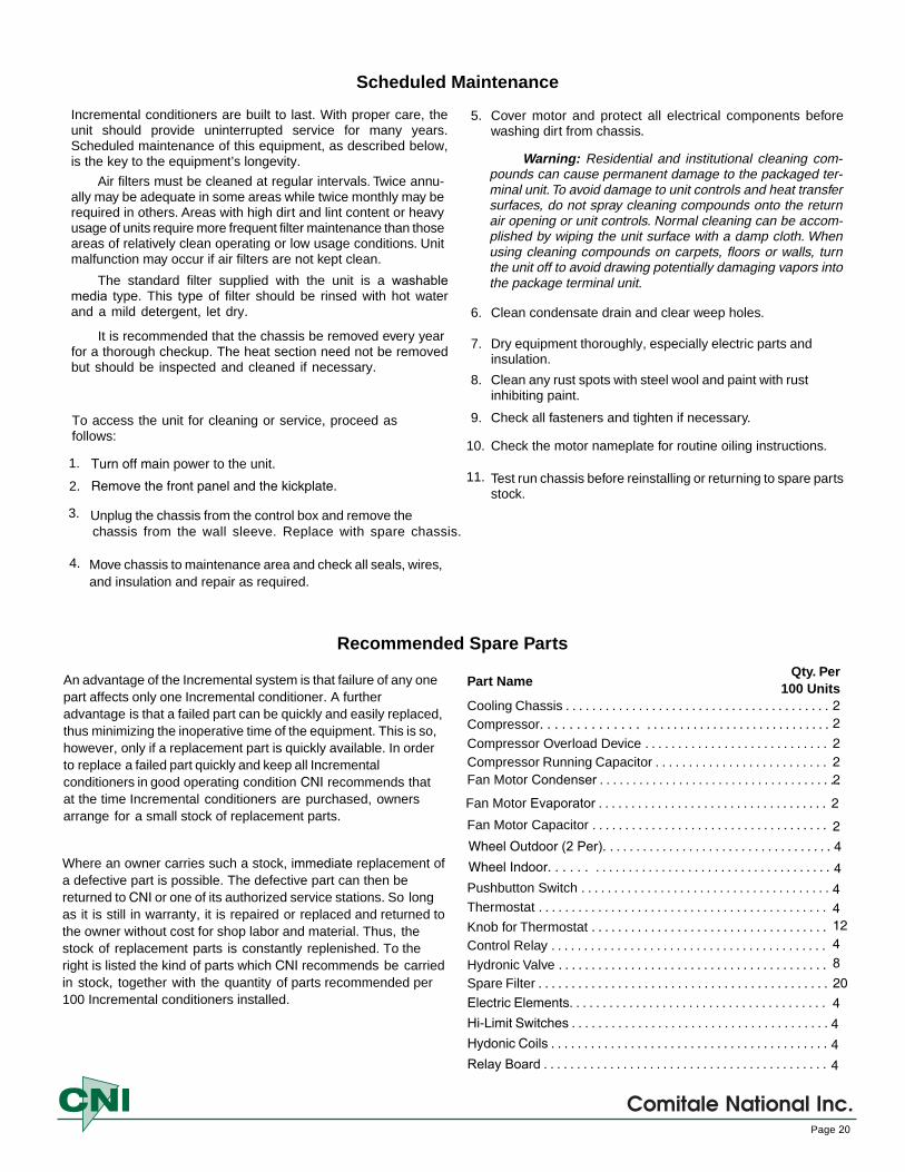
Incremental conditioners are built to last. With proper care, the unit should provide uninterrupted service for many years. Scheduled maintenance of this equipment, as described below, is the key to the equipment’s longevity.
Air filters must be cleaned at regular intervals. Twice annu-ally may be adequate in some areas while twice monthly may berequired in others. Areas with high dirt and lint content or heavyusage of units require more frequent filter maintenance than thoseareas of relatively clean operating or low usage conditions. Unitmalfunction may occur if air filters are not kept clean.
The standard filter supplied with the unit is a washable media type. This type of filter should be rinsed with hot water and a mild detergent, let dry.
It is recommended that the chassis be removed every year for a thorough checkup. The heat section need not be removed but should be inspected and cleaned if necessary.
To access the unit for cleaning or service, proceed as follows:
1.
2.
3. Unplug the chassis from the control box and remove thechassis from the wall sleeve. Replace with spare chassis.
4. Move chassis to maintenance area and check all seals, wires,and insulation and repair as required.
5. Cover motor and protect all electrical components beforewashing dirt from chassis.
Warning: Residential and institutional cleaning com-pounds can cause permanent damage to the packaged ter-minal unit. To avoid damage to unit controls and heat transfersurfaces, do not spray cleaning compounds onto the returnair opening or unit controls. Normal cleaning can be accom-plished by wiping the unit surface with a damp cloth. Whenusing cleaning compounds on carpets, floors or walls, turnthe unit off to avoid drawing potentially damaging vapors intothe package terminal unit.
6. Clean condensate drain and clear weep holes.
7. Dry equipment thoroughly, especially electric parts andinsulation.
8. Clean any rust spots with steel wool and paint with rustinhibiting paint.
9. Check all fasteners and tighten if necessary.
10. Check the motor nameplate for routine oiling instructions.
11. Test run chassis before reinstalling or returning to spare partsstock.
Comitale National Inc.Page 20
Turn off main power to the unit.
Remove the front panel and the kickplate.
Recommended Spare Parts
An advantage of the Incremental system is that failure of any one part affects only one Incremental conditioner. A further advantage is that a failed part can be quickly and easily replaced, thus minimizing the inoperative time of the equipment. This is so, however, only if a replacement part is quickly available. In order to replace a failed part quickly and keep all Incremental conditioners in good operating condition CNI recommends that at the time Incremental conditioners are purchased, owners arrange for a small stock of replacement parts.
Where an owner carries such a stock, immediate replacement of a defective part is possible. The defective part can then be returned to CNI or one of its authorized service stations. So long as it is still in warranty, it is repaired or replaced and returned to the owner without cost for shop labor and material. Thus, the stock of replacement parts is constantly replenished. To the right is listed the kind of parts which CNI recommends be carried in stock, together with the quantity of parts recommended per 100 Incremental conditioners installed.
Part Name
Cooling Chassis . . . . . . . . . . . . . . . . . . . . . . . . . . . . . . . . . . . . . . . .
Compressor Overload Device . . . . . . . . . . . . . . . . . . . . . . . . . . . .Compressor Running Capacitor . . . . . . . . . . . . . . . . . . . . . . . . . .Fan Motor Condenser . . . . . . . . . . . . . . . . . . . . . . . . . . . . . . . . . . . . .
Fan Motor Capacitor . . . . . . . . . . . . . . . . . . . . . . . . . . . . . . . . . . . .
Pushbutton Switch . . . . . . . . . . . . . . . . . . . . . . . . . . . . . . . . . . . . . .
Thermostat . . . . . . . . . . . . . . . . . . . . . . . . . . . . . . . . . . . . . . . . . . . .
Knob for Thermostat . . . . . . . . . . . . . . . . . . . . . . . . . . . . . . . . . . . .Control Relay . . . . . . . . . . . . . . . . . . . . . . . . . . . . . . . . . . . . . . . . . .
Hydronic Valve . . . . . . . . . . . . . . . . . . . . . . . . . . . . . . . . . . . . . . . . .Spare Filter . . . . . . . . . . . . . . . . . . . . . . . . . . . . . . . . . . . . . . . . . . . .
Qty. Per100 Units
2
222
2
4124820
Electric Elements. . . . . . . . . . . . . . . . . . . . . . . . . . . . . . . . . . . . . . .Hi-Limit Switches . . . . . . . . . . . . . . . . . . . . . . . . . . . . . . . . . . . . . . .Hydonic Coils . . . . . . . . . . . . . . . . . . . . . . . . . . . . . . . . . . . . . . . . . .
444
4
Wheel Outdoor (2 Per). . . . . . . . . . . . . . . . . . . . . . . . . . . . . . . . . . .Wheel Indoor. . . . . . . . . . . . . . . . . . . . . . . . . . . . . . . . . . . . . . . . . . 4
4
Compressor. . . . . . . . . . . . . . . . . . . . . . . . . . . . . . . . . . . . . . . . . . 2
Fan Motor Evaporator . . . . . . . . . . . . . . . . . . . . . . . . . . . . . . . . . . . 2
Relay Board . . . . . . . . . . . . . . . . . . . . . . . . . . . . . . . . . . . . . . . . . . . 4

TROUBLESHOOTING CHART
OPERATING FAULT
Compressor will not start - no hum
Compressor will not start - humsbut trips on overload protector
Compressor starts and runs, butshort cycles on overload protector
Unit operates with little or no capacity
Condenser fan and vent motor runs,but compressor will not start
Electric shock from unit
Water drips from unit
Unit vibrates or rattles
POSSIBLE CAUSE
1. Broken or loose wiring
2. Improper wiring
3. Overload protector tripped.
1. Improper wiring
2. Running Capacitor defective
3. Compressor motor has a windingopen or shorted.
4. Internal mechanical trouble incompressor
1. Additional current passing thruoverload protector
2. Overload protector defective
3. Excessive discharge pressure
4. Suction pressure too high
5. Compressor too hot -return suctiongas hot
6. Compressor motor has a windingshorted
1. Shortage of refrigerant
2. Restriction in refrigeration system
3. Dirty condenser
4. Defective TXV, by-pass, or reversingvalves.
5. Inadequate air flow over evaporator
1. Broken or loose wiring
2. Improper wiring
3. Defective running capacitor oncompressor
4. Defective compressor overloadprotector
5. Defective compressor motor
1. Improper grounding of electricalcircuit
1. Condensate drain plugged
2. Chassis damaged
1. Copper tube vibrating
2. Loose components
CORRECTION
1. Check all wiring and connections
2. Check against wiring diagram
3. If external type
1. Check against wiring diagram
2. Determine reason and replace
3. Replace compressor
4. Replace compressor
1. Check against wiring diagram
2. Check current, replace protector(If external type)
3. Check for restrictions in condenserair flow or refrigeration circuit
4. Check for defective valves
5. Check refrigerant charge (fix leak)refrigerant, if necessary. Checkreversing valve operation.
6. Replace compressor
1. Fix leak, recharge
2. Determine location and remove
3. Clean condenser
4. Replace TXV, bypass, or reversingvalves.
5. Clean evaporator coil, check fan,clean filter.
1. Check all wiring
2. Check against wiring diagram
3. Replace capacitor
4. Replace overload Protector.(If external type)
5. Replace compressor
1. Check wiring diagram and provideproper ground
1. Clean drain
2. Repair or replace damaged parts
3. Check installation in wall sleeve.
1. Adjust by bending or apply tape
2. Tighten and adjust as necessary
Comitale National Inc.Page 21
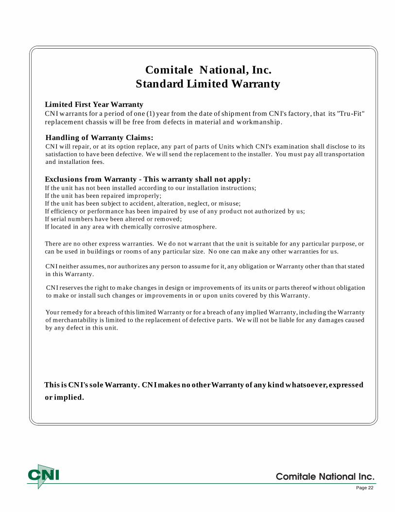
Comitale National, Inc. Standard Limited Warranty
Exclusions from Warranty - This warranty shall not apply:If the unit has not been installed according to our installation instructions;If the unit has been repaired improperly;If the unit has been subject to accident, alteration, neglect, or misuse;If efficiency or performance has been impaired by use of any product not authorized by us;If serial numbers have been altered or removed;If located in any area with chemically corrosive atmosphere.
There are no other express warranties. We do not warrant that the unit is suitable for any particular purpose, orcan be used in buildings or rooms of any particular size. No one can make any other warranties for us.
CNI neither assumes, nor authorizes any person to assume for it, any obligation or Warranty other than that statedin this Warranty.
CNI reserves the right to make changes in design or improvements of its units or parts thereof without obligationto make or install such changes or improvements in or upon units covered by this Warranty.
Your remedy for a breach of this limited Warranty or for a breach of any implied Warranty, including the Warrantyof merchantability is limited to the replacement of defective parts. We will not be liable for any damages causedby any defect in this unit.
This is CNI's sole Warranty. CNI makes no other Warranty of any kind whatsoever, expressed
or implied.
Limited First Year WarrantyCNI warrants for a period of one (1) year from the date of shipment from CNI's factory, that its "Tru-Fit" replacement chassis will be free from defects in material and workmanship.
Handling of Warranty Claims:CNI will repair, or at its option replace, any part of parts of Units which CNI's examination shall disclose to its satisfaction to have been defective. We will send the replacement to the installer. You must pay all transportation and installation fees.
Comitale National Inc.Page 22

C.N.I.Optional Four Year Extended Warranty
Extended WarrantyThe major component parts listed in Table 1 of this Warranty are warranted to be free from defects,under normal installation, use and service for the additional period of time shown in Table 1 of thisWarranty form.
Table 1Major Component Extended Term of Warranty
Component & Products Extended Warranty Period
Motor Compressor:Heat Pump 4 years
Motor Compressor:Air Conditioning Systems 4 years
Refrigeration System 4 years
Description of Refrigeration WarrantyIn addition, C.N.I. warrants that the cooling chassis consisting of compressor, condenser, evaporator,expansion valve, reversing valve and interconnecting piping of the refrigeration section of the units willbe free from defects in material and workmanship for a period of four (4) years immediately followingthe expiration of the Initial Warranty (The Additional Warranty).
Duration of WarrantyThis Warranty begins on the date of shipment from the factory, with the limited first year Warrantyperiod being 12 months and the optional Extended Warranty period being 48 additional months. Re-placement of a part or major component under Warranty does not extend the Warranty term.
What C.N.I. Will DoComitale National, Inc. will provide a free part to replace one which becomes defective during the oneyear Warranty period, or a major component to replace one which becomes defective during the Ex-tended Warranty period listed in Table 1. The replacement may be either new or rebuilt. C.N.I. or ourauthorized distributor will send the replacement to the installer. You must pay all transportation andinstallation charges.
Comitale National Inc.Page 3
Page 23
Comitale National Inc.
Limited First Year Parts WarrantyThe C.N.I. unit is warranted to be free from defects, under normal installation, use and service for one year.

1.
A. C.N.I. will not be liable for any damages caused by any defects in this unit.
6. C.N.I. will not be liable for delays caused by events beyond our control, including war, governmentrestriction, strikes, fire, flood, or other acts of God.
Owners Responsibilities1. Your normal responsibilities as owner are set forth in the instruction manual. Please read it carefully.
2. If you have a Warranty claim, notify your installer promptly. If they do not take care of your claim, writeto Comitale National, Inc., 1683 B Winchester Road, Bensalem, PA 19020, Attn: Warranty Claims. Or email [email protected] Enclose a report of inspection by your installer or service person. Be sure toinclude model number, serial number, and date of purchase.
This Warranty gives you specific legal rights, and you may have other rights which vary with location.
Exclusions from Warranty
Normal maintenance;Transportation and installation charges for replacement parts;Replacement of refrigerant or filters:Any other service calls or repairs.
2. This Warranty does not apply:A. If the unit has not been installed according to our installation instructions;B. To filter media and controls furnished by others;C. To any part or parts of units becoming defective as a result of:
1. Negligence, accident or other casualty.2. Owner failure to provide normal maintenance such as lubrication of motor and bearing, clean-
ing of coils, removal of foreign material from water circuits or to provide protection of unitsfrom freezing water, corrosive atmosphere, or improper voltage.
3. Improper installation, or repair or alteration by anyone other than an authorized C.N.I. agent.4. Operation in any manner contrary to C.N.I.'s printed instructions.
D. To cooling chassis if it has been opened or tampered in any way.E. If serial numbers have been altered or removed.
3. There are no other express warranties. C.N.I. does not warrant that the unit is suitable for any particularpurpose, or can be used in buildings or rooms of any particular size. No one can make any other warrantiesfor C.N.I.
4. Any warranties implied by law, including the implied Warranty of merchantability, are limited in durationto the one year term of the first year parts Warranty.
5. Your remedy for a breach of this limited Warranty or for a breach of any implied Warranty, including theWarranty of merchantability is limited to the replacement of defective parts and listed major components inTable 1.
Comitale National Inc.Page 24
The following expenses are your responsibility:
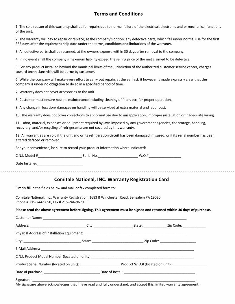
Terms and Conditions
1. The sole reason of this warranty shall be for repairs due to normal failure of the electrical, electronic and or mechanical functionsof the unit.
2. The warranty will pay to repair or replace, at the company's option, any defective parts, which fail under normal use for the first365 days after the equipment ship date under the terms, conditions and limitations of the warranty.
3. All defective parts shall be returned, at the owners expense within 30 days after removal to the company.
4. In no event shall the company's maximum liability exceed the selling price of the unit claimed to be defective.
5. For any product installed beyond the municipal limits of the jurisdiction of the authorized customer service center, chargestoward technicians visit will be borne by customer.
6. While the company will make every effort to carry out repairs at the earliest, it however is made expressly clear that thecompany is under no obligation to do so in a specified period of time.
7. Warranty does not cover accessories to the unit
8. Customer must ensure routine maintenance including cleaning of filter, etc. for proper operation.
9. Any change in location/ damages on handling will be serviced at extra material and labor cost.
10. The warranty does not cover corrections to abnormal use due to misapplication, improper installation or inadequate wiring.
11. Labor, material, expenses or equipment required by laws imposed by any government agencies, the storage, handling,recovery, and/or recycling of refrigerants; are not covered by this warranty.
12. All warranties are void if the unit and or its refrigeration circuit has been damaged, misused, or if its serial number has beenaltered defaced or removed.
For your convenience, be sure to record your product information where indicated:
C.N.I. Model #_______________________ Serial No._____________________ W.O.#_________________
Date Installed________________________
Comitale National, INC. Warranty Registration Card Simply fill in the fields below and mail or fax completed form to:
Comitale National, Inc., Warranty Registration, 1683 B Winchester Road, Bensalem PA 19020 Phone # 2152449650, Fax # 2152449679
Please read the above agreement before signing. This agreement must be signed and returned within 30 days of purchase.
Customer Name: ___________________________________________________________________________
Address: _____________________________ City: ____________________ State: ____________ Zip Code: ____________
Physical Address of Installation Equipment: ______________________________________________________
City: ______________________________ State: ___________________________ Zip Code: ___________________
EMail Address: ________________________________________________________________________________
C.N.I. Product Model Number (located on unity): _____________________________________________________
Product Serial Number (located on unit): _____________________ Product W.O.# (located on unit): __________________
Date of purchase: _____________________________ Date of Install: _____________________________________
Signature: _____________________________________________________________________________________ My signature above acknowledges that I have read and fully understand, and accept this limited warranty agreement.
- - - - - - - - - - - - - - - - - - - - - - - - - - - - - - - - - - - - - - - - - - - - - - - - - - - - - - - - - - - - - - - - - - - - - - - - - - - - - - - - - - - - - - - - - - - - - - - - - - - - - - - - - - - - - - - - - - -

PTAC Check, Test and Start Worksheet(For additional units copy this page) Page _____ of ______
Cooling Heating Damper AmpModel Serial # Room # Installation OK Check Check Working High Fan Low Fan Check
1.
2.
3.
4.
5.
6.
7.
8.
9.
10
11.
12.
13.
14.
15.
16.
17.
18.
19.
20.
21.
22.
23.
24.
25.
26.
27.
28.
29.
30.
31.
32.
33.
34.
35.
36.
37.
38.
39.
40.
41.
42.
Page 26
Comitale National Inc.
Comitale National Inc.
Notes:
____________________________________________________________________________________
____________________________________________________________________________________
____________________________________________________________________________________
____________________________________________________________________________________
____________________________________________________________________________________
____________________________________________________________________________________
____________________________________________________________________________________
____________________________________________________________________________________
____________________________________________________________________________________
____________________________________________________________________________________
____________________________________________________________________________________
____________________________________________________________________________________
____________________________________________________________________________________
____________________________________________________________________________________
____________________________________________________________________________________
Page 27

Comitale National, Inc.1683 B Winchester Road • Bensalem, PA 19020
215-244-9650 • FAX 215-244-9679email:[email protected]
www.comitalenational.com