cruise plan: new horizon 23rd – 29th june 2014...
TRANSCRIPT

Cruise Plan: New Horizon 23rd – 29th June 2014Prepared by Steven Constable and Peter Kannberg May 10, 2014
OVERVIEW OF OPERATIONS
The objective of this cruise is to map the electrical conductivity of the Santa Cruz Basin in the area where a seismicbottom-simulating reflector (BSR) has been observed. BSRs are often associated with gas hydrate, so our objective isto map any occurrence of hydrate in the sediments.
The general setup of the operation is shown in Figure 1. A deep-towed EM transmitter (SUESI) is towed 50-100 mabove the seafloor using the 0.680 coaxial deeptow cable. At a distance of 600 m behind the transmitter is an EMreceiver (Vulcan), with three more Vulcan instruments spaced at 200 m intervals behind the first. The strength memberis a single 1,000 m length kevlar reinforced communication cable from the transmitter to the Vulcans, allowing usto record the depths of the array in real time. Everything except SUESI is trimmed close to neutrally buoyant, afew pounds positive at most. There is a 10 lb mass on the final transponder that can be released acoustically in anemergency. Two surface paravanes towed behind the vessel (Figure 9) are used to acoustically triangulate on thedeeptow transmitter and tail transponder.
We will also deploy 20 of our standard seafloor electric/magnetic field recorders along the lines we plan to tow, andone seafloor current meter. The area of operations is the Santa Cruz Basin, 1000–1900 m water, offshore Long Beach(Figure 2).
CRI P
PS I N
ST
I TU TION OF OCE ANOGRA
PHY
UCS D
0 m 620 m 820 m120.8 m 1020 m 1220 m 1230 m
Transponder for navigationTransponder for navigation “Vulcan” towed 3-axis receivers
Seafloor EM receiver
SUESI - EM transmitter
Figure 1. Schematic of the towed array we will be using.
DESCRIPTION OF INSTRUMENT SYSTEMS
Seafloor electromagnetic recorders: We will have 20 instruments of the type shown in Figure 3. The arms holdingthe electrodes are assembled on deck just prior to deployment and are made of polypropylene. They are tough yetflexible, and so do not necessarily need to be clear of the ship during deployment (and rarely get damaged on recoveryunless run over by a propellor). With concrete anchor the assembly is about 600 lbs and is swung overboard using asmall crate. Release is by stainless steel pelican hook that we provide. The fall speed in water is about 60 m/minute,and so there is little danger of encountering the screws.
We will want to position the vessel on the pre-determined drop locations (Table 1) and come to a full stop. Theinstrument will drift 50-100 m during descent, and so there is no point in trying to position the ship to better than this(i.e. 50–100 m). We can position slowly for the next station while we prepare the next instrument for deployment,which takes 10–15 minutes.
Recovery is by acoustic release system. The instruments rise at 20 m/minute and are equipped with a GPS straylinesystem that will radio the instrument’s location back to the ship. There is also a flag to assist in daylight recoveries,and a flashing strobe to assist with nighttime recoveries. The strayline is connected to the instrument with 10 m of
1
−119˚48'
−119˚48'
−119˚36'
−119˚36'
−119˚24'
−119˚24'
−119˚12'
−119˚12'
33˚24' 33˚24'
33˚36' 33˚36'
33˚48' 33˚48'
34˚00' 34˚00'
−1500
−1500
−1500
−1500
−1500
−1000−1
000
−1000
−500
−500 −500
12
3
45
6 78
1110
9
1213
1415
1617
18
1920
21
Line 4
Line 5
Line 6
Line 1
Line 2
Line 3
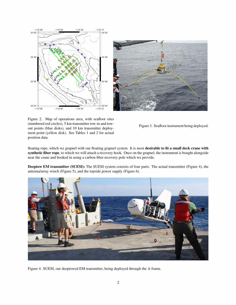
Figure 2. Map of operations area, with seafloor sites(numbered red circles), 5 km transmitter tow-in and tow-out points (blue disks), and 10 km transmitter deploy-ment point (yellow disk). See Tables 1 and 2 for actualposition data.
Figure 3. Seafloor instrument being deployed.
floating rope, which we grapnel with our floating grapnel system. It is most desirable to fit a small deck crane withsynthetic fiber rope, to which we will attach a recovery hook. Once on the grapnel, the instrument is bought alongsidenear the crane and hooked in using a carbon fiber recovery pole which we provide.
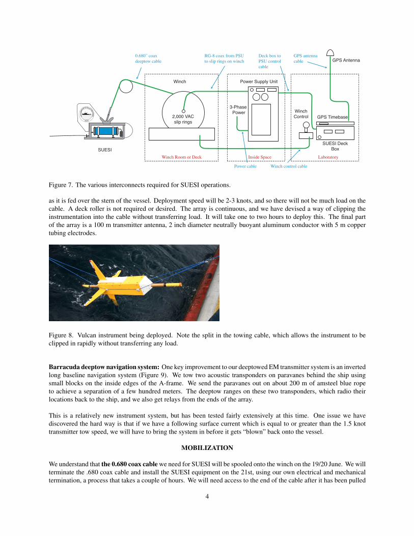
Deeptow EM transmitter (SUESI): The SUESI system consists of four parts: The actual transmitter (Figure 4), theantenna/array winch (Figure 5), and the topside power supply (Figure 6).
Figure 4. SUESI, our deeptowed EM transmitter, being deployed through the A frame.
2

Figure 5. SUESI antenna and array cable spooling winch. Figure 6. SUESI power supply unit (PSU).
The Vulcan array (see next section) and antenna will be deployed from the 7’ × 9’ spooling winch situated on theback deck and bolted down using the 2’ × 2’ deck bolt pattern (Figure 5). The winch weighs about 7,000 lb and usesstandard 480 V 3-phase power (30 amp supply). It has a back-emf type electric breaking system with additional dogsfor safety. The array and antenna are deployed over the stern (seen next section). After the array and antenna havebeen deployed, they will be mechanically and electrically attached to SUESI, our deeptow transmitter. After simpletesting of the transmitter system, SUESI will be deployed through the A-frame (Figure 4). Normally ship’s crew willcontrol the winch from an outdoor winch control station and take the package down to 100 m at 10 m/minute, and thentransfer control to the science party in the main laboratory. Once the package is fully in the water, the nominal shiptow speed is 1.5 knots, not to drop below 1 knot and not to exceed 2 knots.
The power supply unit (PSU) used for SUESI needs to be in an enclosed space (on the New Horizon, aft in the mainlab by the 3-phase power outlet, just inside the main doors) and with access to 3-phase power, preferably 480 V butwe can use anything between 208 and 500 VAC. A 30 amp supply is adequate. The power supply is around 1,500 lbin weight (Figure 6) , and we will take a spare. There will also be a spare SUESI deeptow system stored on the backdeck.
Figure 7 shows the various interconnects required between equipment. The 0.680 coax deeptow cable and the winchcontrol/winch control cable are normally supplied by the vessel. The Deck Box to PSU (power supply unit) cable isprovide by our group, as is the GPS antenna and cable. There are two options for the PSU power cable – we can supplya 3-phase power cable terminated with our connector for direct splice into shipboard power, or we can make a cablewith a specified connector for ship’s power. We have a cable that connects to the 30 A sockets on the New Horizonand other SIO vessels.
We can supply some 2,000 VAC slip rings for the winch ahead of time, although these are sometimes supplied bythe vessel (usually the case for New Horizon). We can also supply the RG-8 cable between the winch and the PSU,although sometimes that is provided by the vessel (ditto).
Vulcan towed EM recorders: Four Vulcans (Figure 8) and two acoustic transponders will be attached to a tow cable
3
CRIPPS IN
STITUTION OF OCEANOG
RAPHY
UCSD
Power Supply Unit
3-Phase Power
Winch
2,000 VACslip rings
SUESISUESI Deck
Box
WinchControl GPS Timebase
GPS Antenna
LaboratoryInside SpaceWinch Room or Deck
RG-8 coax from PSUto slip rings on winch
Deck box toPSU controlcable
Winch control cablePower cable
GPS antenna cable
0.680” coaxdeeptow cable
Figure 7. The various interconnects required for SUESI operations.
as it is fed over the stern of the vessel. Deployment speed will be 2-3 knots, and so there will not be much load on thecable. A deck roller is not required or desired. The array is continuous, and we have devised a way of clipping theinstrumentation into the cable without transferring load. It will take one to two hours to deploy this. The final partof the array is a 100 m transmitter antenna, 2 inch diameter neutrally buoyant aluminum conductor with 5 m coppertubing electrodes.
Figure 8. Vulcan instrument being deployed. Note the split in the towing cable, which allows the instrument to beclipped in rapidly without transferring any load.
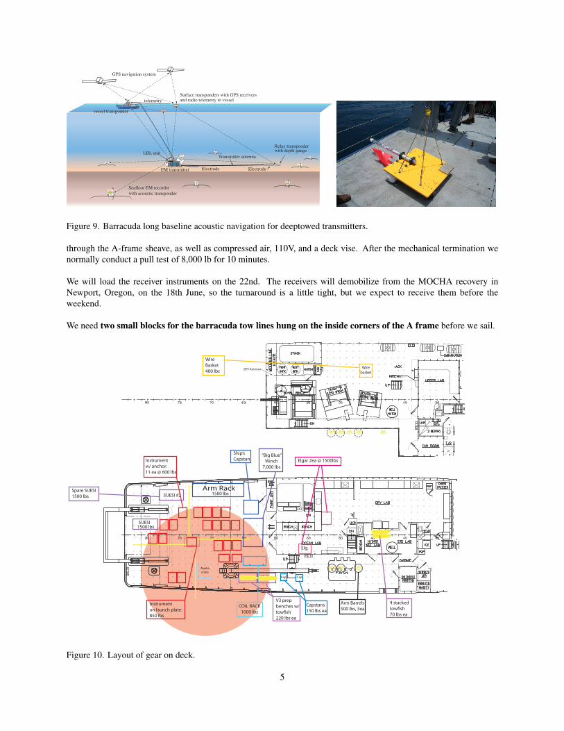
Barracuda deeptow navigation system: One key improvement to our deeptowed EM transmitter system is an invertedlong baseline navigation system (Figure 9). We tow two acoustic transponders on paravanes behind the ship usingsmall blocks on the inside edges of the A-frame. We send the paravanes out on about 200 m of amsteel blue ropeto achieve a separation of a few hundred meters. The deeptow ranges on these two transponders, which radio theirlocations back to the ship, and we also get relays from the ends of the array.
This is a relatively new instrument system, but has been tested fairly extensively at this time. One issue we havediscovered the hard way is that if we have a following surface current which is equal to or greater than the 1.5 knottransmitter tow speed, we will have to bring the system in before it gets “blown” back onto the vessel.
MOBILIZATION
We understand that the 0.680 coax cable we need for SUESI will be spooled onto the winch on the 19/20 June. We willterminate the .680 coax cable and install the SUESI equipment on the 21st, using our own electrical and mechanicaltermination, a process that takes a couple of hours. We will need access to the end of the cable after it has been pulled
4
CRIP
PS IN
ST
ITUTION OF OCEANOGRA
PHY
UCSD
EM transmitter
LBL unit
Seafloor EM recorderwith acoustic transponder
Relay transponderwith depth gauge
Electrode
Transmitter antenna
Surface transponders with GPS receivers and radio telemetry to vessel
GPS navigation system
vessel transponder
Electrode
telemetry
Figure 9. Barracuda long baseline acoustic navigation for deeptowed transmitters.
through the A-frame sheave, as well as compressed air, 110V, and a deck vise. After the mechanical termination wenormally conduct a pull test of 8,000 lb for 10 minutes.
We will load the receiver instruments on the 22nd. The receivers will demobilize from the MOCHA recovery inNewport, Oregon, on the 18th June, so the turnaround is a little tight, but we expect to receive them before theweekend.
We need two small blocks for the barracuda tow lines hung on the inside corners of the A frame before we sail.
Elg.
COIL RACK1000 lbs
Cap.
Alaska crane
Wirebasket
GPS Antenna
Arm Rack
Cap.V3 Prep
SUESI
“Big Blue” Winch
7,000 lbsInstrumentw/ anchor:11 ea @ 600 lbs
Instrumenton launch plate:850 lbs
1500 lbs
Elgar 2ea @ 1500lbs
1500 lbs
V3 prep benches w/tow�sh220 lbs ea
Capstans150 lbs ea
Arm Barrels500 lbs, 3ea
Wire Basket400 lbs
Ship’sCapstan
Spare SUESI1500 lbs SUESI #2
V3 Prep
4 stacked tow�sh70 lbs ea
Figure 10. Layout of gear on deck.
5

Figure 10 shows the layout of the gear on deck. Here is a summary of weights:
2 SUESIs 1,500 lb × 2 back deckSpooling winch 7,000 lb back deck4 Vulcans 200 lb main lab20 seafloor instruments on anchors 600 lb × 20 back deck40 magnetometers in rack 1,000 lbs back deckPower supply unit 1,500 lb × 2 main labbuckets of seawater for electrodes 500 lb × 3 back deckSupport gear 1,000 lb main lab
Our spooling winch needs to be craned aboard and bolted to the deck, which may need a shore crane. SUESI is cranedaboard and tied down beneath the .680 sheave on the A-frame. Instruments are tied down using deck eye bolts.
WORK PLAN
23 June: Sail at 08:00, transit to research area (130 nautical miles, 15 hours). Arrive on station 23:00.
24 June: Deploy seafloor current meter. Deploy 20 OBEM receivers, 5 km station spacing, 18 minuteseach (6 hours). Deploy Vulcan array and SUESI (4 hours). Start SUESI tows at 09:00.
25–27 June: SUESI tows.
28 June: Finish SUESI tows at 08:00. Recover SUESI and Vulcan array (4 hours). Recover 20 OBEMinstruments, 36 minutes per site (12 hours).
29 June: Leave station at 00:00. Transit to port (15 hours). Tie up at 16:00.
Our plan will give 95 hours of transmitter operation, which at 1.5 – 1.7 knots is 260 line kilometers (which includesturns).
1 -119 35.2359 33 45.9832 -119 33.9769 33 46.99633 -119 32.7888 33 47.95324 -119 35.3737 33 42.86735 -119 33.511 33 44.36956 -119 32.2735 33 45.36677 -119 31.0943 33 46.3178 -119 29.2292 33 47.81829 -119 33.1943 33 40.827410 -119 31.3264 33 42.324511 -119 30.1123 33 43.296812 -119 28.9411 33 44.234813 -119 27.0707 33 45.730914 -119 31.4521 33 39.196815 -119 29.5813 33 40.690916 -119 28.3869 33 41.644217 -119 27.2228 33 42.573118 -119 25.3495 33 44.066319 -119 27.86 33 39.07620 -119 26.687 33 40.013121 -119 25.5319 33 40.9354
Site Longitude LattitudeSeafloor Sites
Line 1 SW-119 40.3564 33 38.8476Line 2 SW-119 38.3583 33 36.6874Line 3 SW-119 36.686 33 35.0153Line 4 NW-119 39.1315 33 54.0794Line 5 NW-119 41.0695 33 53.7816Line 6 NW-119 44.1119 33 54.2823
Line 1 NE-119 24.6831 33 51.4773Line 2 NE-119 22.5199 33 49.3712Line 3 NE-119 20.798 33 47.6944Line 4 SE-119 19.6326 33 35.2239Line 5 SE-119 20.7566 33 34.3261Line 6 SE-119 21.8559 33 33.4484
5km tow in points
10 km tow in pointLine 1 SW-119 42.6796 33 36.9678
Table 1: Seafloor instrument site locations. Table 2: Deep-tow beginning and end locations.
6

Table 3. Personnel.
CONSTABLE STEVEN UCSD Chief Scientist 1. UC EmployeeARMERDING CHRIS UCSD Technician 1. UC EmployeeKANNBERG PETER UCSD Graduate Student 1. UC EmployeeKEY KERRY UCSD Scientist 1. UC EmployeeALEXANDER JAMES UCSD Volunteer 2. UC VolunteerPEREZ JACOB UCSD Technician 1. UC EmployeeSOUDERS JOHN UCSD Technician 1. UC EmployeePeter Kowalczyk OFG Observer 3. Non UC EmployeeAntony Wass OFG Observer 3. Non UC EmployeeToru Kasuga Fukada Observer 3. Non UC EmployeeMatt Frye BOEM Observer 3. Non UC Employee
OFG = Ocean Floor GeophysicsFukada = Fukada Salvage & Marine Works.
7