cryogenic structural materials of the iter toroidal field
TRANSCRIPT
Cryogenic Structural Materials of the ITER Toroidal Field Coil Structure
Masahide Iguchi1, Takeru Sakurai1, Masataka Nakhira1, Norikiyo Koizumi1, and Hideo Nakajima1 1National Institutes for Quantum and Radiological Science and Technology (QST),
Abstract
The International Thermonuclear Experimental Reactor (ITER) is a large-scale experimental facility that aims to demonstrate the engineering and physical feasibility of fusion energy. The ITER Toroidal Field coils (TFCs) is one of the coils in the ITER superconducting magnet system, which have a welded D-shape with a height of 16.5m, a width of 9m and a weight of about 300 tons, are among the most important components in the ITER superconducting magnet system. All the structural materials used in the TFC cases are full austenitic stainless steels and are classified into four grades depending on stress distribution in the TFC case. The requirements are that yield strength at 4K are larger than 1000MPa, 900MPa, 700MPa, 500MPa and that fracture toughness at 4K is larger than 180MPam0.5.
For thirty years, QST has developed new cryogenic structural materials for the next Fusion Experimental Reactor in collaboration with Japanese steel companies. The targets for mechanical properties were set as yield strength >1200MPa and fracture toughness > 200MPam0.5. From five candidate materials, finally two high manganese stainless steels have been successfully developed. These two materials became commercially available based on a demonstration of their productivity and weldability of materials, and evaluations of 4 K mechanical properties of trial products including welded parts.
For the highest grade of ITER TFC case, JJ1was selected from two developed materials taking into account of matching of thermal contraction to stainless steel, 316LN. For the remaining three material grades, QST made industrial specifications by controlling nitrogen contents of 316LN corresponding to stress requirements based on the results of material manufacturing trials and mechanical tests at 4K. QST has standardized these specifications of 316LN and JJ1 as a material section of "Codes for Fusion Facilities - Rules on Superconducting Magnet Structure (2008)" issued by the Japan Society of Mechanical Engineers in October 2008.
As the final evaluation prior to starting actual material manufacturing, QST manufactured actual shape materials and confirmed satisfactory results of mechanical properties at 4K. After this qualification, manufacturing of structural materials for actual TFC cases started from in August 2012. This paper describes the history of the development of cryogenic structural materials and the status of TFC case manufacturing.
Introduction
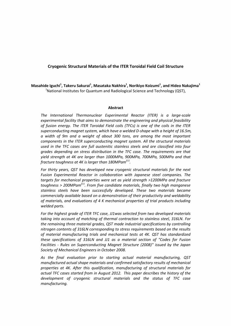
In nuclear fusion, there are two types of reactors stable enough to conduct nuclear fusion: magnetic confinement reactors and inertial confinement reactors. The former method of fusion seeks to lengthen the time that ions spend in close proximity in order to fuse them together. The Tokamak [1] is one example of a magnetic the concepts of magnetic confinement reactors whose magnetic system is shown in Figure 1. The Tokamak is a device that uses a magnetic field to confine plasma in the shape of a torus. The Tokamak has a magnet system to confine the plasma as fuel for fusion reaction. Usually three types of coils are installed in a Tokamak; toroidal field coils (TFC) to generate the field to confine charged particles in the plasma, the second is poloidal field coils (PFC) to generate the position equilibrium of plasma current (i.e., the fields to confine the plasma pressure) and the plasma vertical stability, and the third is inner poloidal field coils to provide the inductive flux to ramp up plasma current and contribute to plasma shaping.
On Earth fusion fuel must be heated to extreme temperatures of the order of 100 million degrees Celsius, and must be kept dense enough, and confined for long enough time to allow the nuclei to fuse. On the other hands, in the sun, massive gravitational forces create the right conditions for fusion. To realize similar conditions of sufficient density confinement, a high magnetic field and large Tokamak device are necessary. The application of superconducting magnet coils has been found to be a solution to obtain the high magnetic field. From the 1980s, research and development of the application of large superconducting coils to fusion experimental reactors has been conducted; for example, the Large Coil Task (LCT) was an international research activity [2].
The application of large superconducting coils requires high strength and very durable cryogenic structural materials because the large coil size, high current and high field generate a high Lorenz force on the coil in superconducting temperature. In Japan, National Institutes for Quantum and Radiological Science and Technology (QST) - (Japan Atomic Energy Research Institute (JAERI) up to 2006, and Japan Atomic Energy Agency (JAEA) from 2006 to March 2016) - set the design properties of Japanese Fusion Experimental Reactor (FER) [3], including a development goal of cryogenic structural materials, which was planned to be superseded by the existing large Tokamak called JT-60. QST, along with four Japanese steel industries, have developed cryogenic structural materials for the FER since 1982, and the results of this development were applied to the International Thermonuclear Experimental Reactor (ITER) TFC structure whose manufacturing started in 2012. A timeline of the four phases of QST involvement in cryogenic structural materials is shown below:
I: Development Phase (1982- 1990) II: Industrialization Phase (1992 - 2001) III: Commercialization Phase (2002 - 2012) IV: Actual manufacturing for ITER (2012- present)
This paper describes a summary of each phase and provides a progress of the procurement of the ITER TFC Structure.
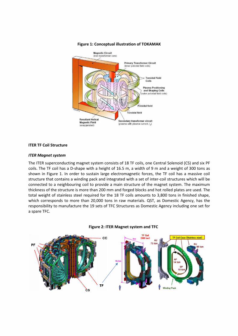
Figure 1: Conceptual illustration of TOKAMAK
ITER TF Coil Structure
ITER Magnet system
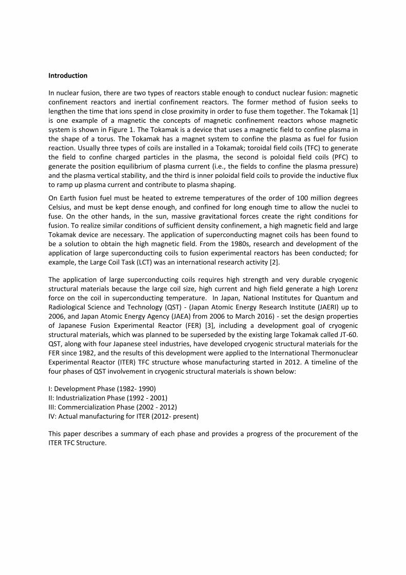
The ITER superconducting magnet system consists of 18 TF coils, one Central Solenoid (CS) and six PF coils. The TF coil has a D-shape with a height of 16.5 m, a width of 9 m and a weight of 300 tons as shown in Figure 1. In order to sustain large electromagnetic forces, the TF coil has a massive coil structure that contains a winding pack and integrated with a set of inter-coil structures which will be connected to a neighbouring coil to provide a main structure of the magnet system. The maximum thickness of the structure is more than 200 mm and forged blocks and hot rolled plates are used. The total weight of stainless steel required for the 18 TF coils amounts to 3,800 tons in finished shape, which corresponds to more than 20,000 tons in raw materials. QST, as Domestic Agency, has the responsibility to manufacture the 19 sets of TFC Structures as Domestic Agency including one set for a spare TFC.
Figure 2: ITER Magnet system and TFC
Structural Materials for ITER TFC Structure
Cryogenic structural materials having both high strength and toughness are used in ITER TFC Structures because they have to withstand large magnetic forces at 4K. Although an over 200mm thick forging is used in the inner leg of TFC Structure, high stress is generated in this part and the maximum static stress intensity is about 667 MPa [4]. However, generated stress has distribution along a coil perimeter and there are different strength requirements on yield strength (YS) of materials used in TFC Structure. Figure 3 shows present ITER requirements on YSs of TFC Structure. The materials are classified into 4 grades of materials. The highest grade material of C1 class has YS of over 1,000 MPa, the second of C2 class has 900 MPa, the third of C3 class has 700 MPa, and the fourth of C4 class has 500 MPa, respectively. And for all material grades, fracture toughness, KIc, over 180MPa m0.5 is required as the specification. In the ITER TFC Structure, developed cryogenic structural material is applied to highest material grade and for the other material grades three material grades of 316LN are applied by controlling Nitrogen and Carbon (C+N) contents according to QST development results.
Figure 3: Classification of material grade according to required design strengths in ITER TFC structure
Development Phase (1982-1990)
Background and setting the development target
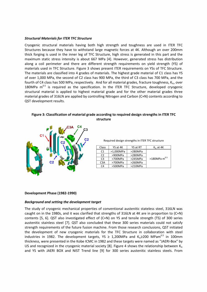
The study of cryogenic mechanical properties of conventional austenitic stateless steel, 316LN was caught on in the 1980s, and it was clarified that strengths of 316LN at 4K are in proportion to (C+N) contents [5, 6]. QST also investigated effect of (C+N) on YS and tensile strength (TS) of 300 series austenitic stainless steel [7]. QST also concluded that these 300 series materials could not satisfy strength requirements of the future fusion machine. From those research conclusions, QST initiated the development of new cryogenic materials for the TFC Structure in collaboration with steel industries in 1982. The development targets, YS ≥ 1,200MPa and KIc≥200 MPam0.5 in 100mm thickness, were presented in the Kobe ICMC in 1982 and these targets were named as “JAERI-Box” by US and recognized in the cryogenic material society [8]. Figure 4 shows the relationship between KIc and YS with JAERI BOX and NIST Trend line [9] for 300 series austenitic stainless steels. From
Class YS at 4K YS at RT KIc at 4K
C1 >1,000MPa >280MPa
>180MPa m0.5
C2 >900MPa >280MPa C3 >700MPa >245MPa
C3A >700MPa >260MPa C4 >500MPa >210MPa
Required design strengths in ITER TFC structure
comparisons of JAERI-BOX and NIST Trend line, one can understand that the development target was very high at that time.
Development of new cryogenic materials
QST evaluated cryogenic strength and KIc of many materials, for example, over 100 for tensile properties, produced by steel industries. After screening tests, 5 materials were nominated as candidates of cryogenic structural materials for the Japanese FER, which were named as JN1 [10, 11], JKA1 [12], JN2 [13, 14], JK2 [15], JJ1 [16] with high N contents (N> 0.20%mass). Chemical compositions of these 5 materials are tabulated in Table 1. In Table 1, these 5 materials are categorized into three types of materials, two are high Cr-Ni type (JN1 and JKA1), two are high Mn (JK2, JN2), and one has medium chemical composition (JJ1). All developed materials have N contents over 0.20%mass to be strengthened by its solid solution strengthening.
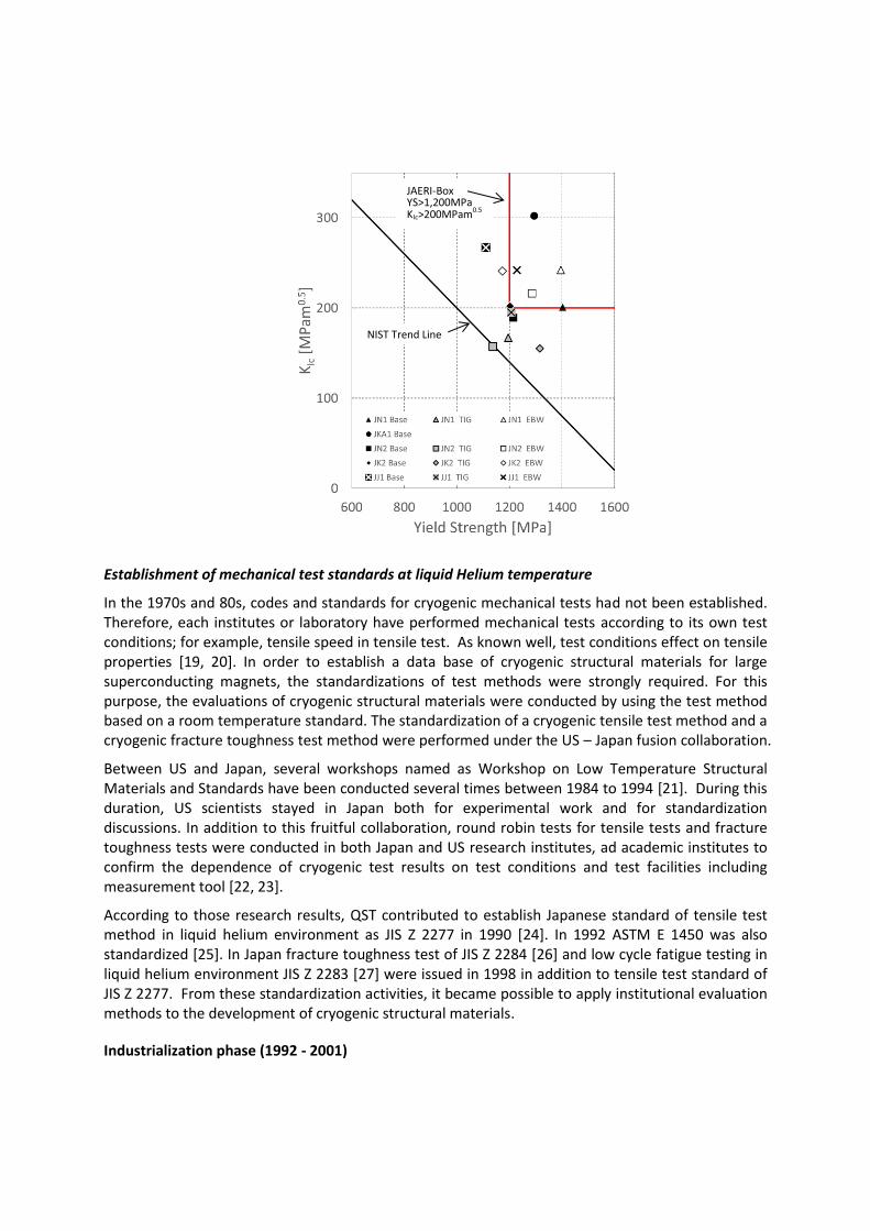
The relationship of mechanical test results between YS and KIc are shown in Figure 4 with JAERI BOX and NIST Trend Line. It can be said all test results are higher than the NIST trend line of commercial 316L and 304L properties. In addition to base metal mechanical properties, cryogenic mechanical properties of weldments have been also confirmed by application of Tungsten inert gas (TIG) welding and electron beam welding (EBW) [17, 18]. Test results also are described in Figure 4. With consideration for both of base metal and welded metal mechanical properties, these 5 developed metals were selected as candidate materials for the Japanese FER.
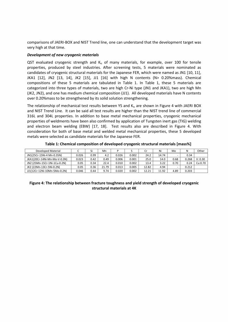
Table 1: Chemical composition of developed cryogenic structural materials [mass%]
Developed Material C Si Mn P S Cr Ni Mo N Other
JN1(25Cr-15Ni-4 Mn-0.35N) 0.026 0.99 4.2 0.026 0.002 24.2 14.74 - 0.34
JKA1(20Cr-14Ni-Mn-Mo-V-0.3N) 0.023 0.42 0.49 0.006 0.001 25.0 14.0 0.68 0.268 V: 0.30
JN2 (25Mn-15Cr-1Ni-1Cu-0.2N) 0.05 0.34 22.4 0.010 0.002 13.4 3.22 0.70 0.24 Cu:0.70
JK2 (22Mn-13Cr-5Ni-0.2N) 0.05 0.36 21.79 0.013 0.005 12.82 4.94 - 0.212
JJ1(12Cr-12Ni-10Mn-5Mo-0.2N) 0.046 0.44 9.74 0.020 0.002 12.21 11.92 4.89 0.203
Figure 4: The relationship between fracture toughness and yield strength of developed cryogenic structural materials at 4K
Establishment of mechanical test standards at liquid Helium temperature
In the 1970s and 80s, codes and standards for cryogenic mechanical tests had not been established. Therefore, each institutes or laboratory have performed mechanical tests according to its own test conditions; for example, tensile speed in tensile test. As known well, test conditions effect on tensile properties [19, 20]. In order to establish a data base of cryogenic structural materials for large superconducting magnets, the standardizations of test methods were strongly required. For this purpose, the evaluations of cryogenic structural materials were conducted by using the test method based on a room temperature standard. The standardization of a cryogenic tensile test method and a cryogenic fracture toughness test method were performed under the US – Japan fusion collaboration.
Between US and Japan, several workshops named as Workshop on Low Temperature Structural Materials and Standards have been conducted several times between 1984 to 1994 [21]. During this duration, US scientists stayed in Japan both for experimental work and for standardization discussions. In addition to this fruitful collaboration, round robin tests for tensile tests and fracture toughness tests were conducted in both Japan and US research institutes, ad academic institutes to confirm the dependence of cryogenic test results on test conditions and test facilities including measurement tool [22, 23].
According to those research results, QST contributed to establish Japanese standard of tensile test method in liquid helium environment as JIS Z 2277 in 1990 [24]. In 1992 ASTM E 1450 was also standardized [25]. In Japan fracture toughness test of JIS Z 2284 [26] and low cycle fatigue testing in liquid helium environment JIS Z 2283 [27] were issued in 1998 in addition to tensile test standard of JIS Z 2277. From these standardization activities, it became possible to apply institutional evaluation methods to the development of cryogenic structural materials.
Industrialization phase (1992 - 2001)
JAERI-Box YS>1,200MPa KIc>200MPam0.5
NIST Trend Line

Preparation for ITER
In 1985, the ITER project was proposed by former Soviet Union Premier Gorbachev and former US President Reagan during the Geneva superpower summit. From 1988 to 1990, Conceptual Design Activities (CDA) were s performed by EU, Japan, Russia, and the USA [28]. After completion of CDA, Engineering Design Activities (EDA) were conducted from 1992 to 2001 to finalize the ITER design and resolve technical issues [29]. During the EDA, required maximum design strength for cryogenic structural material of the TFC Structure was optimized to YS ≥ 1,000MPa and KIc≥200 MPam0.5 , but the assumed maximum thickness became over 200mm (thicker than that of the Japanese FER). EDA results showed applicability of 316LN material with adding nitrogen for strengthening of structural parts having low stress distribution. From this new design requirement, JJ1 and JK2 were selected as candidates for the ITER TFC Structure material because of unnecessary high YS like JN1 of 1,400MPa, and their weldability and manufacturability compared with other developed materials.
In order to confirm base metal and welded metal’s mechanical properties of thick JJ1 and JK2, materials having some thickness over 100mm were manufactured. Manufactured material information is tabulated in Table 2. In addition to base metal, weld joints were manufactured by using these base metals and welding filler of similar composition metals.
Mechanical test results for base and weld joints are shown in Figure 5. Figure 5 shows all test results satisfied new ITER criteria. From these results, it can be said that JJ1 and JK2 were successfully developed including welding material and their mechanical properties were demonstrated by industrial level materials over 10-ton ingots. [30-32] However, it was found that these two materials have deferent thermal contraction from room temperature to 4K, which would be brought by high manganese content, compared with 316LN. The thermal contraction from room temperature of JJ1 and JK2 are about 0.28% and 0.20%, respectively. Since a matching of thermal contraction should be considered to avoid high thermal stress, JJ1 is adapted as structural material for inboard structure of ITER TFC Structures where high stress is occurred because thermal contraction value is almost same as 316LN (0.3 %). On the other hand, JK2 is modified into JK2LB [33, 34] to withstand Nb3Sn heat treatment by adjusting chemical compositions (low carbon and B addition). JK2LB is used as a jacket martial in the ITER CS conductor taking advantage of low thermal contraction and high resistance of crack growth [35].
On the other hand, for outboard structure where lower stress occurred more than in inboard structure, 316LN is applied. However, standard 316LN of ASTM having nitrogen contents from 0.1 to 0.16mass% could not satisfy outboard stress. Hence, 316LN by adding nitrogen should be considered. In order to define the specification of strengthened 316LN according to required design strengths, effects of (C+N) and variation of material strengths was assessed by researching previous data [7, 36-40]. These chemical composition are tabulated in Table 3 as preliminary commercial specification of chemical compositions.
Table 2: Production of materials in Industrialization phase
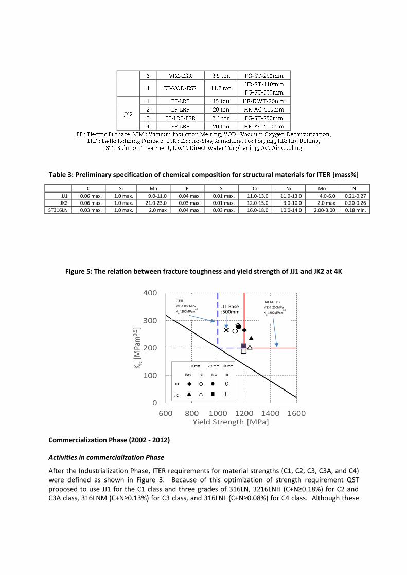
Table 3: Preliminary specification of chemical composition for structural materials for ITER [mass%]
C Si Mn P S Cr Ni Mo N
JJ1 0.06 max. 1.0 max. 9.0-11.0 0.04 max. 0.01 max. 11.0-13.0 11.0-13.0 4.0-6.0 0.21-0.27
JK2 0.06 max. 1.0 max. 21.0-23.0 0.03 max. 0.01 max. 12.0-15.0 3.0-10.0 2.0 max 0.20-0.26
ST316LN 0.03 max. 1.0 max. 2.0 max 0.04 max. 0.03 max. 16.0-18.0 10.0-14.0 2.00-3.00 0.18 min.
Figure 5: The relation between fracture toughness and yield strength of JJ1 and JK2 at 4K
Commercialization Phase (2002 - 2012)
Activities in commercialization Phase
After the Industrialization Phase, ITER requirements for material strengths (C1, C2, C3, C3A, and C4) were defined as shown in Figure 3. Because of this optimization of strength requirement QST proposed to use JJ1 for the C1 class and three grades of 316LN, 3216LNH (C+N≥0.18%) for C2 and C3A class, 316LNM (C+N≥0.13%) for C3 class, and 316LNL (C+N≥0.08%) for C4 class. Although these
JAERI-Box YS>1,200MPa K
Ic>200MPam
0.5
ITER
YS>1,000MPa K
Ic>200MPam
0.5
JJ1 Base :500mm
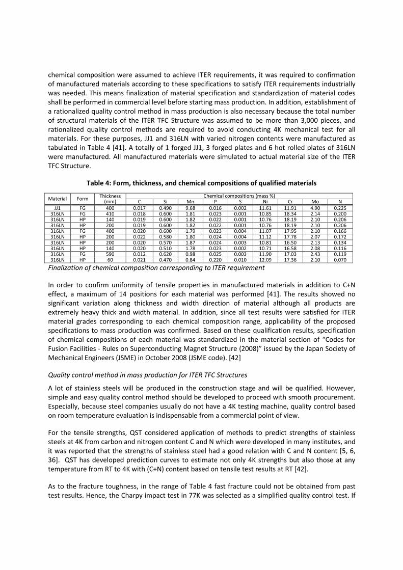
chemical composition were assumed to achieve ITER requirements, it was required to confirmation of manufactured materials according to these specifications to satisfy ITER requirements industrially was needed. This means finalization of material specification and standardization of material codes shall be performed in commercial level before starting mass production. In addition, establishment of a rationalized quality control method in mass production is also necessary because the total number of structural materials of the ITER TFC Structure was assumed to be more than 3,000 pieces, and rationalized quality control methods are required to avoid conducting 4K mechanical test for all materials. For these purposes, JJ1 and 316LN with varied nitrogen contents were manufactured as tabulated in Table 4 [41]. A totally of 1 forged JJ1, 3 forged plates and 6 hot rolled plates of 316LN were manufactured. All manufactured materials were simulated to actual material size of the ITER TFC Structure.
Table 4: Form, thickness, and chemical compositions of qualified materials
Material Form Thickness (mm)
Chemical compositions (mass %) C Si Mn P S Ni Cr Mo N
JJ1 FG 400 0.017 0.490 9.68 0.016 0.002 11.61 11.91 4.90 0.225 316LN FG 410 0.018 0.600 1.81 0.023 0.001 10.85 18.34 2.14 0.200 316LN HP 140 0.019 0.600 1.82 0.022 0.001 10.76 18.19 2.10 0.206 316LN HP 200 0.019 0.600 1.82 0.022 0.001 10.76 18.19 2.10 0.206 316LN FG 400 0.020 0.600 1.79 0.023 0.004 11.07 17.95 2.10 0.166 316LN HP 200 0.022 0.580 1.80 0.024 0.004 11.12 17.78 2.07 0.172 316LN HP 200 0.020 0.570 1.87 0.024 0.003 10.81 16.50 2.13 0.134 316LN HP 140 0.020 0.510 1.78 0.023 0.002 10.71 16.58 2.08 0.116 316LN FG 590 0.012 0.620 0.98 0.025 0.003 11.90 17.03 2.43 0.119 316LN HP 60 0.021 0.470 0.84 0.220 0.010 12.09 17.36 2.10 0.070
Finalization of chemical composition corresponding to ITER requirement
In order to confirm uniformity of tensile properties in manufactured materials in addition to C+N effect, a maximum of 14 positions for each material was performed [41]. The results showed no significant variation along thickness and width direction of material although all products are extremely heavy thick and width material. In addition, since all test results were satisfied for ITER material grades corresponding to each chemical composition range, applicability of the proposed specifications to mass production was confirmed. Based on these qualification results, specification of chemical compositions of each material was standardized in the material section of “Codes for Fusion Facilities - Rules on Superconducting Magnet Structure (2008)” issued by the Japan Society of Mechanical Engineers (JSME) in October 2008 (JSME code). [42]
Quality control method in mass production for ITER TFC Structures
A lot of stainless steels will be produced in the construction stage and will be qualified. However, simple and easy quality control method should be developed to proceed with smooth procurement. Especially, because steel companies usually do not have a 4K testing machine, quality control based on room temperature evaluation is indispensable from a commercial point of view.
For the tensile strengths, QST considered application of methods to predict strengths of stainless steels at 4K from carbon and nitrogen content C and N which were developed in many institutes, and it was reported that the strengths of stainless steel had a good relation with C and N content [5, 6, 36]. QST has developed prediction curves to estimate not only 4K strengths but also those at any temperature from RT to 4K with (C+N) content based on tensile test results at RT [42].
As to the fracture toughness, in the range of Table 4 fast fracture could not be obtained from past test results. Hence, the Charpy impact test in 77K was selected as a simplified quality control test. If
the Charpy test result is lower than specification (absolutely energy of 100J for ITER TFC Structure), then the fracture toughness test at 4K will be considered.
The prediction method for fatigue property has been developed in the industrialization phase and this phase. Two prediction methods have been assessed. One is the Langer method [43]; the other is a conjugate gradient method (Manson’s equation) [44]. In the prediction of RT fatigue property, the Langer method has a higher accuracy than Manson’s equation, but in the case of 4K, Manson’s equation showed higher accuracy than the Langer method based on the comparison between the equation and measured data [45]. Finally, Manson’s equation with measured properties of 316LN having C+N of 0.08% was adopted as a base curve for the design curve. The fatigue design curve (1/20 of fatigue life or a half of stress amplitude, whichever is smaller) was defined in design section of JSME Code.
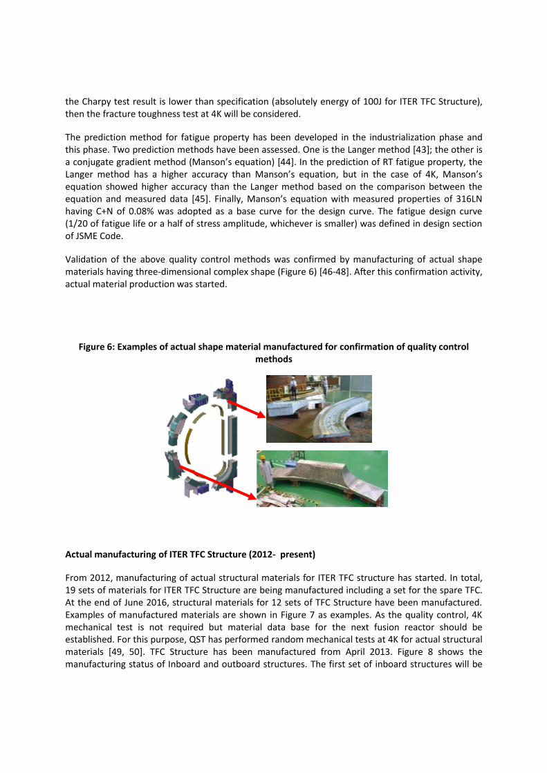
Validation of the above quality control methods was confirmed by manufacturing of actual shape materials having three-dimensional complex shape (Figure 6) [46-48]. After this confirmation activity, actual material production was started.
Figure 6: Examples of actual shape material manufactured for confirmation of quality control methods
Actual manufacturing of ITER TFC Structure (2012- present)
From 2012, manufacturing of actual structural materials for ITER TFC structure has started. In total, 19 sets of materials for ITER TFC Structure are being manufactured including a set for the spare TFC. At the end of June 2016, structural materials for 12 sets of TFC Structure have been manufactured. Examples of manufactured materials are shown in Figure 7 as examples. As the quality control, 4K mechanical test is not required but material data base for the next fusion reactor should be established. For this purpose, QST has performed random mechanical tests at 4K for actual structural materials [49, 50]. TFC Structure has been manufactured from April 2013. Figure 8 shows the manufacturing status of Inboard and outboard structures. The first set of inboard structures will be

finished by August of 2016, and the first set of outboard structures will be manufactured by the end of 2016.
Summary
Since 1980s QST has developed cryogenic structural materials having high strength and fracture toughness at liquid helium temperature with Japanese steel companies. Finally five cryogenic austenite stainless steel materials were developed. A worldwide requirement for mechanical test standards at liquid helium temperature and a tensile test standard in cryogenic temperature was established in collaboration with the US. In addition, fracture toughness and low cycle fatigue test at liquid helium temperature were also standardized as Japanese Industrial Standard (JIS). After the decision to join the ITER project, JJ1 (12Cr-12Ni-10Mn-5Mo-0.2N) and JK2LB (13Cr-9Ni-22Mn-1Mo-0.15N-0.004B) were selected as a highest grade material of coil case and a jacket material of Central Solenoid, respectively. In addition, rationalized quality control methods were developed based on predictions of cryogenic mechanical properties at test results on room temperature. These results were the basis of “Codes for Fusion Facilities - Rules on Superconducting Magnet Structure (2008)”, which is used in TER TF coil. Following the preparation phase actual structural materials for the ITER TFC Structure was started in 2012 and manufacturing of the ITER TFC Structure successfully began in 2013.
Figure 7: Actual structural materials for ITER TFC Structures
JJ1 large forging (860mm width, 250mm thickness,
7,600mm length)
C3 material being longest forging (910mm width,
133mm thickness, 9200mm length) C2 material being complicate shape
forging
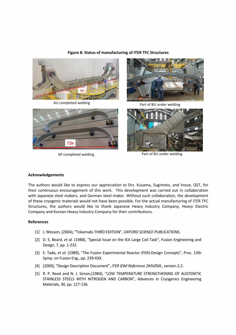
Figure 8: Status of manufacturing of ITER TFC Structures
Acknowledgements
The authors would like to express our appreciation to Drs. Kusama, Sugimoto, and Inoue, QST, for their continuous encouragement of this work. This development was carried out in collaboration with Japanese steel makers, and German steel maker. Without such collaboration, the development of these cryogenic materials would not have been possible. For the actual manufacturing of ITER TFC Structures, the authors would like to thank Japanese Heavy Industry Company, Heavy Electric Company and Korean Heavy Industry Company for their contributions.
References
[1] J. Wesson, (2004), “Tokamaks THIRD EDITION”, OXFORD SCIENCE PUBLICATIONS.
[2] D. S. Beard, et al. (1988), “Special Issue on the IEA Large Coil Task”, Fusion Engineering and Design, 7, pp. 1-232.
[3] E. Tada, et al. (1989), “The Fusion Experimental Reactor (FER)-Design Concepts”, Proc. 13th Symp. on Fusion Eng., pp. 239-XXX.
[4] (2009), “Design Description Document”, ITER IDM Reference 2MVZNX., version 2.2.
[5] R. P. Reed and N. J. Simon,(1984), “LOW TEMPERATURE STRENGTHENING OF AUSTENITIC STAINLESS STEELS WITH NITROGEN AND CARBON”, Advances in Cryogenics Engineering Materials, 30, pp. 127-136.
AU completed welding Part of BU under welding
Part of BU under welding AP completed welding
[6] N. J. Simon and R. P. Reed, (1986) “STRENGTH AND TOUGHNESS OF AISI 304 AND 316 AT 4K”, Journal of Nuclear Materials 141-143, pp.44-48.
[7] Y. Takahashi, et al. (1982), “MECHANICAL EVALUATION OF NITROGEN-STRENTHENED STAINLESS STEELS AT 4k”, Advances in Cryogenics Engineering Materials, 28, pp. 73-81.
[8] K. Yoshida, et al. (1983), “DEVELOPMENT OF CRYOGENIC STRUCTURAL MATERIALS FOR TOKAMAK REACTOR”, Austenitic Steels at Low Temperature, Plenum Press, NewYork, pp. 29-39.
[9] J. A. Shepic, (1979), Materials Studies for Magnetic Fusion Energy Applications at LowTemperatures-II, Nat. Bur. Standards. Boulder, CO.
[10] T. Sakamoto, Y. Nakagawa,I. Yamauchi, T. Zaizen, H. Nakajima and S. Shimamoto, (1984), “NITROGEN-CONTAINING 25Cr-13Ni STAINLESS STEEL AS A CRYOGENIC STRUCTRAL MATERIAL”, Advancesin Cryogenic Engineering Materials, 30, pp. 137-144.
[11] K. Suemune,T. Sakamoto,T. Ogawa,T. Okazaki, S. Maehara, H. Nakajima and S. Shimamoto, (1988), “MANUFACTURING AND PROPERTIES AOF NITROGEN-CONTAINING Cr-Mn AND Cr-Ni AOUSTENITIC STAILESS STEELS FOR CRYOGENIC USE”, Advancesin Cryogenic Engineering Materials, 34, pp. 123-129.
[12] K. Nohara M. Shimotomai and Y. Habu, (1989), “CRYOGENIC PROPERTIES OF NEW AUSTENITIC STAILESS STEEL FOR FUSION REACTOR SUPERCONDUCTOING MAGNETS”, J. Nuclear Mater., 169, pp. 264-269.
[13] H. Masumoto,K. Suemune,H. Nakajima and S. Shimamoto, (1984), “DEVELOPMENT OF HIGH-STRENGTH HIGH MANGANESE STAILESS STEEL FOR CRYOGENIC USE”, Advancesin Cryogenic Engineering Materials, 30, pp. 169-176.
[14] K. Suemune,K. Sugino, H. Masumoto,H. Nakajima and S. Shimamoto, (1986), “IMPROVEMENT OF TOUGHNESS OF A HIGH-STRENGTH, HIGH-MANGANIESE STAINLESS STEEL FOR CRYOGENIC USE”, Advancesin Cryogenic Engineering Materials, 32, pp. 51-56.
[15] S. Tone, M. Shimada,T. Horiuchi, Y. Kasamatsu,H. Nakajima and S. Shimamoto, (1984), “THE DEVELOPMENT OF A NITROGEN-STRENGTHNED HIGH-MANGANESE AUTENITIC STAINLESS STEEL FOR A LARGE SUPERCONDUCTING MAGNET”, Advancesin Cryogenic Engineering Materials, 30, pp. 145-152.
[16] J. Ishizaka, R. Miura, H. Nakajima and S. Shimamoto, (1990), “Strength and Toughness of 12Cr-12Ni-10Mn-5Mo Steel for Cryogenic Structural Application”, Tetsu-to-Hagani, 76, pp. 149-156 (in Japanese).
[17] S. Tone, M. Hiromatsu. J. Numata.T. Horiuchi, H. Nakajima and S. Shimamoto, (1986), “CRYOGENIC PROPERTYIES IF ELECTRON-BEAM WELDED JOINTS IN A 22Mn-13Cr-5Ni-0.22N AUSTENITIC STAINLESS STEEL”, Advancesin Cryogenic Engineering Materials, 32, pp. 89-96.
[18] T. Ogawa,T. Koseki, S. Ohkita and H. Nakajima, (1990), “4K Properties of High-Nitrogen Stainless Steel Weldments”, Weld. J., 69, No. 6, pp. 205s-212s.
[19] T. Ogata, K. Ishikawa, and K. Nagai, (1985), “Effects of Strain Rate on the Tensile Behavior of Stainless Steels, Copper, and an Aluminum Alloy at Cryogenic Temperatures”, Testu-to-Hagane, 71-10, pp. 122-129.
[20] H. M. Lee, R. P. Reed, and J. K. Han, (1990) “LOAD-CONTROLLED TENSILE TESTS OF AUSTENITIC STEELS AT 4K”, Advancesin Cryogenic Engineering Materials, 36, pp. 1273-1282.
[21] H. Nakajima, K. Yoshida and S. Shimamoto, (1986) “Development of Cryogenic Structural Materials and Structural Design Standards From Viewpoint of Superconducting Coil Development for Fusion Reactor”, TEION KOUGAK, 21, 4, pp. 197-204.
[22] H. Nakajima, et al. (1988), “ROUND ROBIN TENSILE AND FRACTURE TEST RESULTS FOR AN Fe-22Mn-13Cr-5Ni AUSTENITIC STAINLESS STEEL AT 4K”, Advancesin Cryogenic Engineering Materials, 34, pp. 241-249.
[23] H. Nakajima, et al. (1997), “INTERLAVORATORYTENSION AND FRACTURE TOUGHNESS TEST RESURTS FOR CSUS-JN1 AUSTENITIC STAINLESS STEEL AT 4K”, Advancesin Cryogenic Engineering Materials, 36, pp. 1069-1076.
[24] JIS Z 2277, (1990), “Method of Tensile Tesing for Metallic Materials in Liquid Helium”.
[25] ASTM E 1450, (1992), “Standard Test Method for Tension Testing of Structural Alloys in Liquid Helium”.
[26] JIS Z 2284, (1998), “Method of elastic-plastic fracture toughness JIC testing for metallic materials in liquid helium”.
[27] JIS Z 2283, (1998), “Method of low cycle fatigue tesing for metallic materials in liquid helium”.
[28] IAEA, (1991), “ITER CONCEPTUAL DESIGN REPORT”, ITER DOCUMENTATION SERIES, 18,
[29] IAEA, (1991), “Summary of the ITER Final Design Report”, ITER EDA DOCUMENTATION SERIES, 22,
[30] K. Ishio, H. Nakajima, T. Kawasaki, S. Uehara, H. Tsuji, (1997), “Mechanical properties of 110mm thick hot rolled plates of JJ1 and JK2 for ITER TF coil”, Proc. of 15th Int. Conf. on Magnet Technology (MT-15),pp. 989-992.
[31] K. Ishio, H. Nakajima, Y. Nunoya, Y. Miura, T. kawasaki, H. Tsuji (1998), “Trial Fabrication of Heavy Section Base Metals and Welded Joints for ITER TF Coil”, Advances in Cryogenic Engineering Materials, 44, pp. 73-80.
[32]H. Nakajima, K. Hamada, K. Okuno, J. Hada, E. Tada, (2002), “NEW CRYOGENIC STEELS AND DESIGN APPROACH FOR ITER SUPERCONDUCTING MAGNET SYSTEM”, Proceedings of ICONE10, pp. 1-8.
[33] K. Hamada, et al. (2006), “Demonstration of JK2LB jacket fabrication for ITER Central Solenoid”, IEEE Trans. Appl. Supercond., 16, pp. 787-790.
[34] K. Hamada, et al. (2007), “Optimization of JK2LB chemical composition for ITER Central Solenoid conduit material”, Cryogenics, 47, pp. 174-182.
[35] K. Hamada, et al. (2008), “Development of Conduits for the ITER Central Solenoid Conductor”, TEIONKOGAKU, 43, 6, pp. 224-251.
[36] K. Ishio and H. Nakajima, (2006), “Effects of nitrogen on the mechanical properties of 316LN stainless steels,” Tetsu-to-Hagane, vol. 92, pp. 30–35.
[37] A. Nyilas, D. R. Harries, and G. Bevilacqua, (2000), “Status of European martial testing program for ITER model coils and full size mockups,” Advances in Cryogenic Engineering Materials, vol. 46, pp. 443–450.
[38] A. Nyilas, A. Portone, and H. Kiesel, (2002), “European cryogenic material program, for ITER coils and intercoil structures,” Adv. Cryogenic Eng. Mater., vol. 48, pp. 123–130.
[39] E. S. Drexler, N. J. Simon, and R. P. Reed, (1994), “Strength and toughness at 4K of forged, heavy-section 316LN,” Adv. Cryogenic Eng. Mater., vol. 40, pp. 1199–1206.
[40] T. Ogata, K. Nagai, K. Ishikawa, K. Shibata, and S. Murase, (1992), “VAMAS second round robin test of structural materials at liquid helium temperature,” Adv. Cryogenic Eng. Mater., 38, pp. 69-76.
[41] H. Nakajima, et al. (2009), “QUALIFICATION OF CRYOGENIC STRUCTURAL MATERIALS FOR THE ITER TOROIDAL FIELD COILS”, Proceedings of the ASME 2009 Pressure Vessels and Piping Division Conference, PVP2009- 77553, pp. 1-8.
[42] Japan SME, (2008), “Codes of Fusion Facilities –Rules on Superconducting magnet Structure-“, JSME S KA1-2008, Maruzen.
[43] Langer, B. F., (1971), "Design of Pressure Vessels Involving Fatigue," Pressure Vessel Engineering, R. W. Nichols, Editor, Elsevier Publishing Co., Amsterdam.
[44] S.S. Manson (1965), “Fatigue: a complex subject-some simple approximation”, Exp Mech, 5, pp. 193-226.
[45] H. nakajima, et al. (2004), “Prediction of fatigue characteristics of nitrogen strengthened austenitic stainless steel at cryogenic temperature”, Abstruct of CSSJ Conference, 71, p.245.
[46] M. Iguchi, et al.(2011), “Estimation of Tensile Strengths at 4K of 316LN Forging and Hot Rolled Plate for the ITER Toroidal Field Coils", Advances in Cryogenic Engineering Materials, 58, pp. 70-77.
[47] M. Iguchi, et al. (2012), “Development of structures for ITER Toroidal Field Coil in Japan", IEEE Trans. Appl. Supercond., 22, No3, 4203305.
[48] H. Nakajima, et al. (2012), “ITER Magnet Systems - from Qualification to Full Scale Construction”, Proceedings of 24th IAEA Fusion Energy Conference, October 8-13, San Diego, USA, 535, ITR-2.
[49] T. Sakurai, et al. (2014), “Accuracy of prediction method of cryogenic tensile strength for austenitic stainless steels in ITER toroidal field coil structure”, Physics Procedia, 67, pp. 536-542.
[50] T. Sakurai, et al. (2015), “Cryogenic tensile properties assessment of actual materials for ITER TF Coil Structure”, Abstruct of CSSJ Conference, 91, p. 159.
“The views and opinions expressed herein do not necessarily reflect those of the ITER Organization”