cryogenic thermal insulation systems€¦ · systems are targeted for large-scale cryogenic...
TRANSCRIPT

Aug 2005 CryoTestLab 1
Cryogenic Thermal Insulation Systems
16th Thermal and Fluids Analysis WorkshopOrlando, FloridaAugust 9, 2005
James E. Fesmire
Stan D. Augustynowicz
Cryogenics Test Laboratory
NASA Kennedy Space Center
Aug 2005 CryoTestLab 2
Outline
Introduction Part 1, MaterialsPart 2, TestingPart 3, ApplicationsConclusion

INTRODUCTION
HEAT IS THE ENEMY
Aug 2005 CryoTestLab 5
Two things about cryogenics
Store a lot of stuff in a small spaceEnergy density
Use the cold temperature to do something useful
Refrigeration
Space launch and exploration is an energy intensive endeavor; cryogenics is an energy intensive discipline.

Aug 2005 CryoTestLab 6
Cryogenics now touches on nearly every aspect of modern society
FoodHealth and medicineEnergyTransportationManufacturingResearchAerospace
Aug 2005 CryoTestLab 7
Cryogenics on Earth and in space
Cryogens must be stored, handled, and transferred in safe and effective waysCryogenic usage and application is being extended to the rest of the world in the first half this centuryPeople working in cryogenics are becoming more and more specialized
Aug 2005 CryoTestLab 8
For progress and efficiency into the 21st century, high performance thermal insulation systems are needed….
Aug 2005 CryoTestLab 9
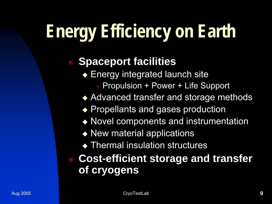
Energy Efficiency on EarthSpaceport facilities
Energy integrated launch sitePropulsion + Power + Life Support
Advanced transfer and storage methodsPropellants and gases productionNovel components and instrumentationNew material applicationsThermal insulation structures
Cost-efficient storage and transfer of cryogens
Aug 2005 CryoTestLab 10
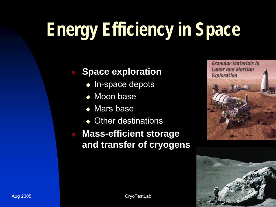
Energy Efficiency in Space
Space explorationIn-space depotsMoon baseMars baseOther destinations
Mass-efficient storage and transfer of cryogens
Aug 2005 CryoTestLab 11
Energy Efficiency for Industry
IndustryHydrogen TransportationSuperconducting PowerProcesses & Applications
Aug 2005 CryoTestLab 12
Thermal Insulation SystemsSystem Integrated Approach
Active + PassiveHot Side + Cold Side
Energy and Economics Perspective
Performance must justify the costSave $$ on energy bill
Two Things About InsulationConserve energy (or mass)Provide control of system
PART 1MATERIALS
Aug 2005 CryoTestLab 14
BackgroundHistorical perspective
D’Arsonval in 1887 to Peterson in 1951WW II to H2 bomb to Apollo
Conventional materialsPerlite to multilayer to foam
Novel materialsAerogels to sol-gel aerogelsComposites old and composites new
Aug 2005 CryoTestLab 15
Basics about Materials
Three Basic FormsBulk FillFoamsLayered
Basic Design FactorsDefinitions: k-value and CVP
Aug 2005 CryoTestLab 16
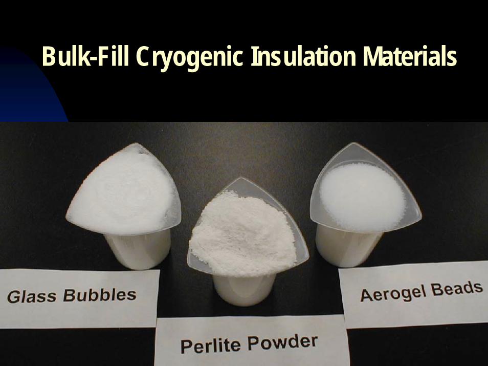
Bulk-Fill Cryogenic Insulation Materials
Aug 2005 CryoTestLab 17
New MaterialsCabot, aerogel beads (Nanogel®)Aspen Aerogels, aerogel blankets (Pyrogel® and Spaceloft®)Sordal, polyimide foams (SOLREX®)Inspec Foams, polyimide foams (SOLIMIDE®)TAI, pipe insulation panelsNASA, Layered Composite Insulation (LCI)
Aug 2005 CryoTestLab 18
Performance
Price versus performance R5 or R1500, its your (extreme) choiceOverall Efficiency, four basic factors:
1. Thermal conductivity2. Vacuum level ($$$)3. System density or weight4. Cost of labor ($$) and materials ($)
Aug 2005 CryoTestLab 19
1. Thermal ConductivityMaterial thermal conductivity
milliWatt per meter-Kelvin [mW/m-K]R-value per inch [hr-ft2-degF/Btu-in]1 mW/m-K = R144
Apparent thermal conductivityk-valueReal systems with large temperature differences
Overall k-value for actual field installationkoafiOften one order of magnitude (or more!) higher than reported ideal or laboratory k-values
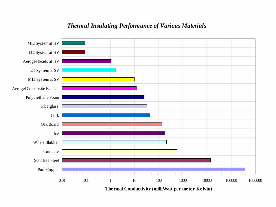
Thermal Insulating Performance of Various Materials
0.01 0.1 1 10 100 1000 10000 100000 1000000
Pure Copper
Stainless Steel
Concrete
Whale Blubber
Ice
Oak Board
Cork
Fiberglass
Polyurethane Foam
Aerogel Composite Blanket
MLI System at SV
LCI System at SV
Aerogel Beads at HV
LCI System at HV
MLI System at HV
Thermal Conductivity (milliWatt per meter-Kelvin)
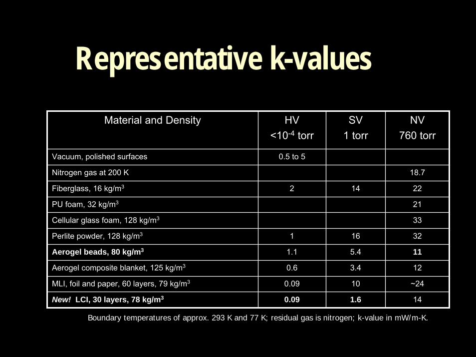
Representative k-valuesMaterial and Density HV
<10-4 torrSV
1 torrNV
760 torr
Vacuum, polished surfaces 0.5 to 5
Nitrogen gas at 200 K 18.7
Fiberglass, 16 kg/m3 2 14 22
PU foam, 32 kg/m3 21
Cellular glass foam, 128 kg/m3 33
Perlite powder, 128 kg/m3 1 16 32
Aerogel beads, 80 kg/m3 1.1 5.4 11
Aerogel composite blanket, 125 kg/m3 0.6 3.4 12
MLI, foil and paper, 60 layers, 79 kg/m3 0.09 10 ~24
New! LCI, 30 layers, 78 kg/m3 0.09 1.6 14
Boundary temperatures of approx. 293 K and 77 K; residual gas is nitrogen; k-value in mW/m-K.
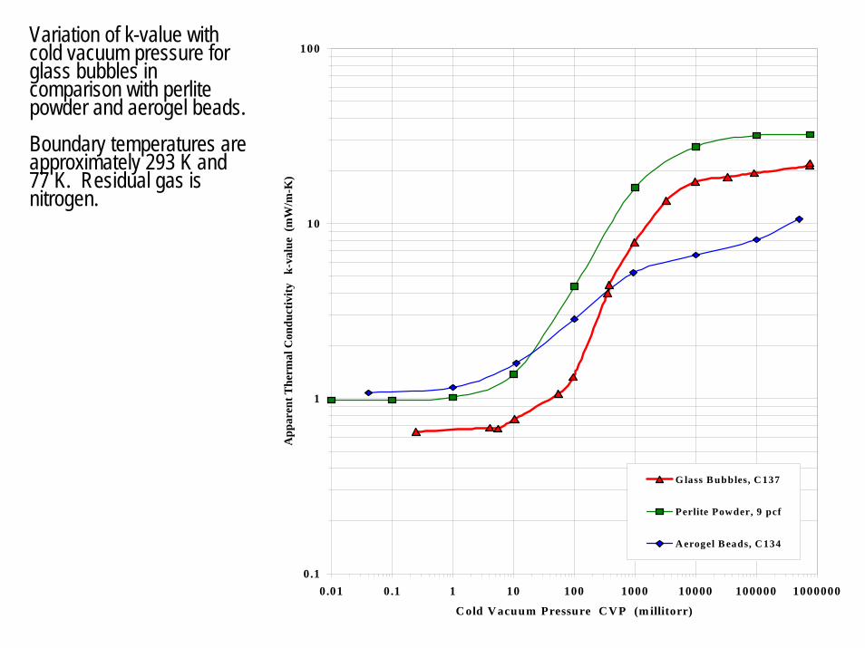
Variation of k-value with cold vacuum pressure for glass bubbles in comparison with perlite powder and aerogel beads. Boundary temperatures are approximately 293 K and 77 K. Residual gas is nitrogen.
0.1
1
10
100
0.01 0.1 1 10 100 1000 10000 100000 1000000
C old V acuum Pressure C V P (m illitorr)
App
aren
t The
rmal
Con
duct
ivity
k-
valu
e (m
W/m
-K)
G lass B ubbles, C 137
Perlite Powder, 9 pcf
A erogel B eads, C 134
1
1 0
1 0 0
1 0 0 0
0 .1 1 1 0 1 0 0 1 0 0 0 1 0 0 0 0 1 0 0 0 0 0 1 0 0 0 0 0 0C o ld V a c uum P ressure C V P (m illito rr)
Hea
t Flu
x (W
/m2)
and
Tot
al H
eat (
W)
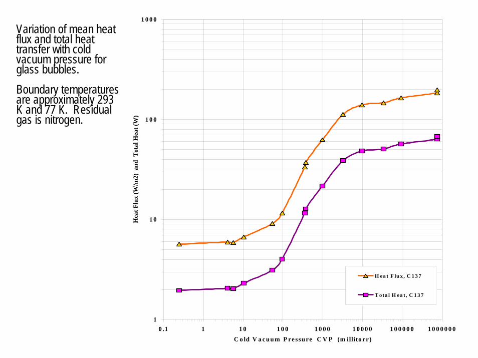
H ea t F lu x , C 1 3 7
T ota l H ea t, C 1 3 7
Variation of mean heat flux and total heat transfer with cold vacuum pressure for glass bubbles. Boundary temperatures are approximately 293 K and 77 K. Residual gas is nitrogen.
Aug 2005 CryoTestLab 24
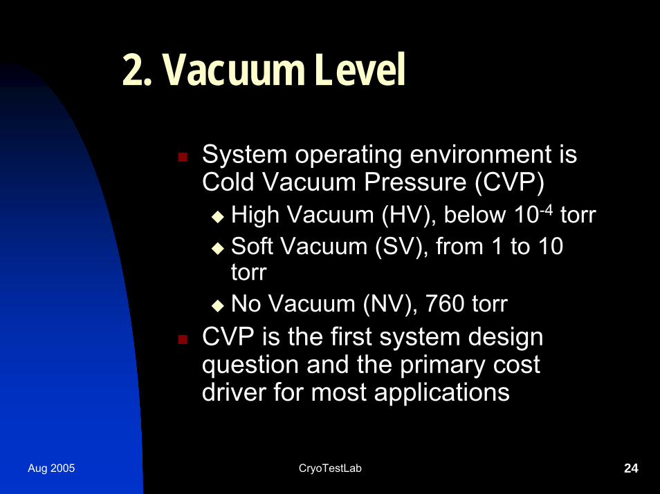
2. Vacuum LevelSystem operating environment is Cold Vacuum Pressure (CVP)
High Vacuum (HV), below 10-4 torrSoft Vacuum (SV), from 1 to 10 torrNo Vacuum (NV), 760 torr
CVP is the first system design question and the primary cost driver for most applications
Aug 2005 CryoTestLab 25
3. Density
Total installed density (or weight) is often critical for transportation applicationsDensity, as related to thermal mass, is also important for control of process systems
Aug 2005 CryoTestLab 26
4. Cost
Performance must justify the costTotal heat flow, through insulation and all other sources, determines thermal performance requirementsManufacturing, maintenance, and reliability considerations are the key for determining overall cost
Aerogel Materials
LIGHTER THAN AIR?LIGHTER THAN AIR?
Aug 2005 CryoTestLab 28
Aerogel Basics
World’s lightest solidLighter is not always betterSpecial class of open-pore structure nano-materials
Extremely low density (as low as several mg/cm3)High porosity (up to 99%)High surface area (over 1000 m2/g)Ultrafine pore size (as small as 2-nm radius)
Derived from the supercritical drying of highly cross-linked inorganic or organic gels
Sol-Gel processing methods
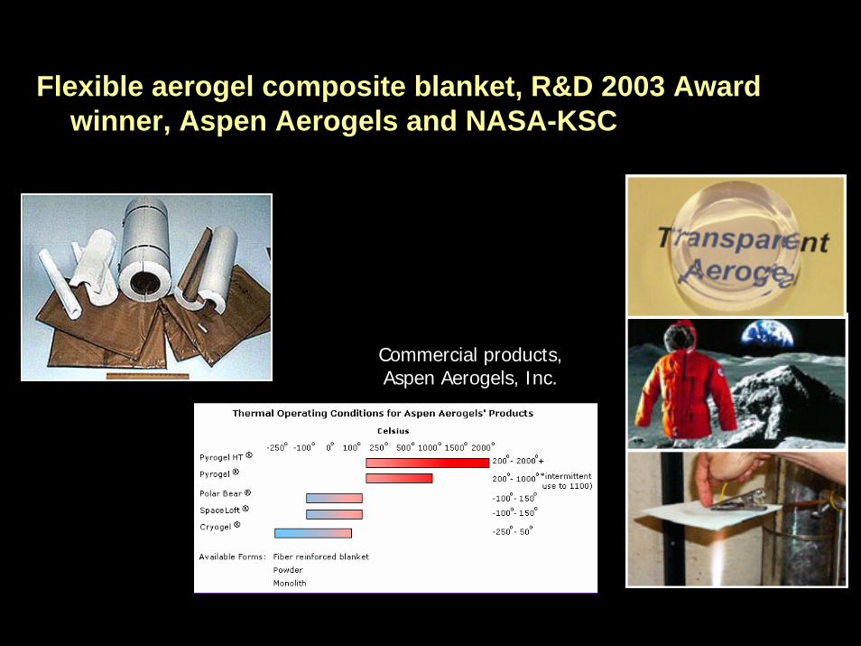
Flexible aerogel composite blanket, R&D 2003 Award winner, Aspen Aerogels and NASA-KSC
Commercial products, Aspen Aerogels, Inc.
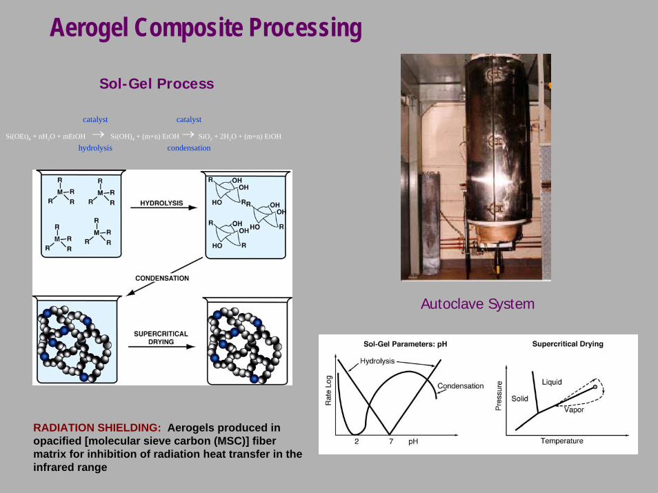
Aerogel Composite Processing
Sol-Gel Process
catalyst catalyst
condensationhydrolysisSi(OEt)4 + nH2O + mEtOH Si(OH)4 + (m+n) EtOH SiO2 + 2H2O + (m+n) EtOH
← ←
Autoclave System
RADIATION SHIELDING: Aerogels produced in opacified [molecular sieve carbon (MSC)] fiber matrix for inhibition of radiation heat transfer in the infrared range
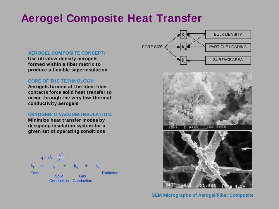
Aerogel Composite Heat Transfer
PORE SIZE
SURFACE AREA
PARTICLE LOADING
BULK DENSITYks
kg
kr
AEROGEL COMPOSITE CONCEPT:Use ultralow density aerogels formed within a fiber matrix to produce a flexible superinsulation
CORE OF THE TECHNOLOGY:Aerogels formed at the fiber-fiber contacts force solid heat transfer to occur through the very low thermal conductivity aerogels
CRYOGENIC-VACUUM INSULATION:Minimize heat transfer modes by designing insulation system for a given set of operating conditions
SolidConduction
GasConduction
kt = ks + kg + kr
∆T∆ Lq = kA
Total Radiation
SEM Micrographs of Aerogel/Fiber Composite
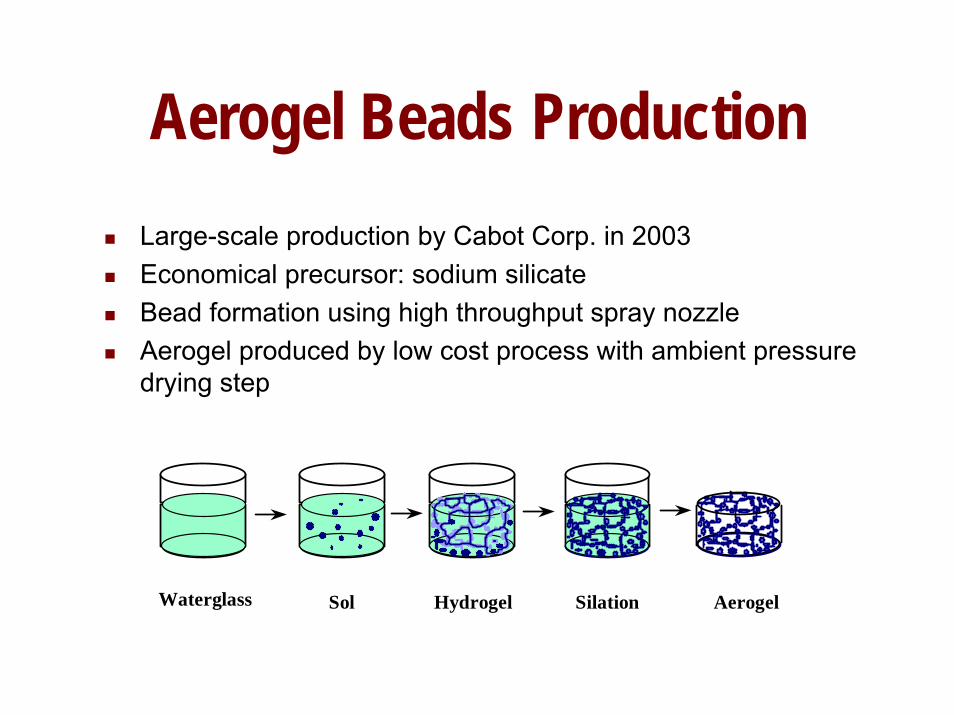
Aerogel Beads ProductionLarge-scale production by Cabot Corp. in 2003Economical precursor: sodium silicateBead formation using high throughput spray nozzleAerogel produced by low cost process with ambient pressure drying step
Waterglass Sol Hydrogel AerogelSilation
PART 2TESTING
Aug 2005 CryoTestLab 34
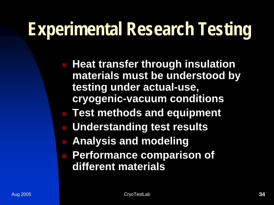
Experimental Research TestingHeat transfer through insulation materials must be understood by testing under actual-use, cryogenic-vacuum conditionsTest methods and equipment Understanding test resultsAnalysis and modelingPerformance comparison of different materials
Aug 2005 CryoTestLab 35
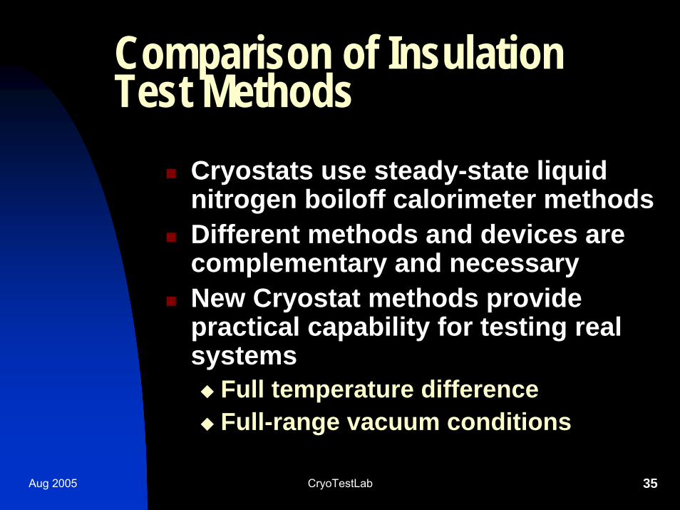
Comparison of Insulation Test Methods
Cryostats use steady-state liquid nitrogen boiloff calorimeter methodsDifferent methods and devices are complementary and necessaryNew Cryostat methods provide practical capability for testing real systems
Full temperature differenceFull-range vacuum conditions
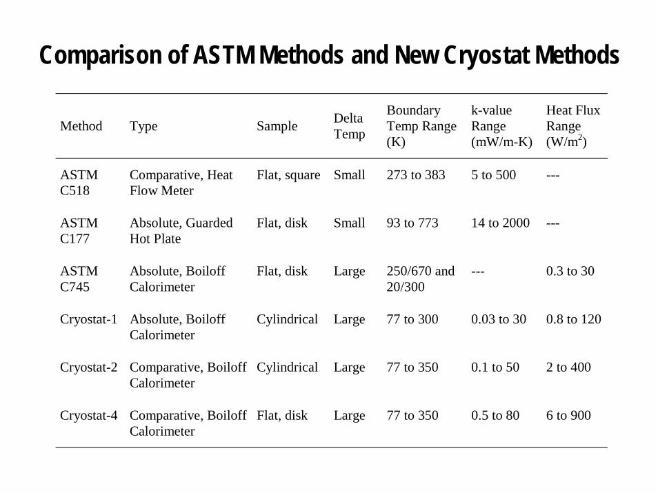
Comparison of ASTM Methods and New Cryostat Methods
Method Type Sample Delta Temp
Boundary Temp Range (K)
k-value Range (mW/m-K)
Heat Flux Range (W/m2)
ASTM C518
Comparative, Heat Flow Meter
Flat, square Small 273 to 383 5 to 500 ---
ASTM C177
Absolute, Guarded Hot Plate
Flat, disk Small 93 to 773 14 to 2000 ---
ASTM C745
Absolute, Boiloff Calorimeter
Flat, disk Large 250/670 and 20/300
--- 0.3 to 30
Cryostat-1 Absolute, Boiloff Calorimeter
Cylindrical Large 77 to 300 0.03 to 30 0.8 to 120
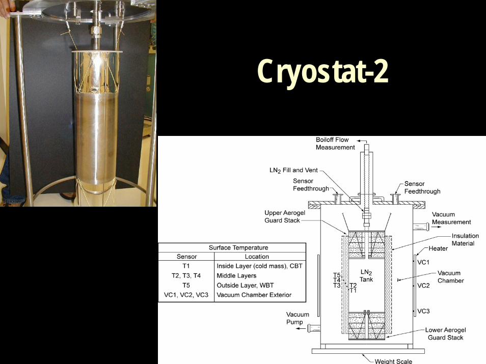
Cryostat-2 Comparative, Boiloff Calorimeter
Cylindrical Large 77 to 350 0.1 to 50 2 to 400
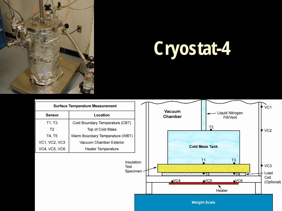
Cryostat-4 Comparative, Boiloff Calorimeter
Flat, disk Large 77 to 350 0.5 to 80 6 to 900
Aug 2005 CryoTestLab 37
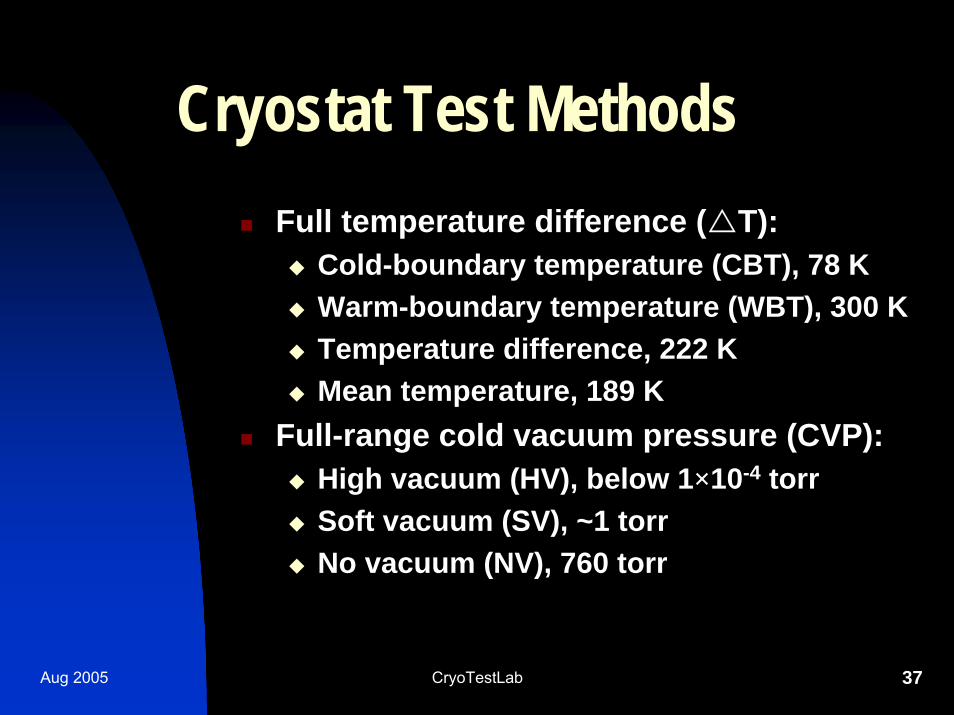
Cryostat Test MethodsFull temperature difference ( T):
Cold-boundary temperature (CBT), 78 KWarm-boundary temperature (WBT), 300 KTemperature difference, 222 KMean temperature, 189 K
Full-range cold vacuum pressure (CVP):High vacuum (HV), below 1×10⁻⁴ torrSoft vacuum (SV), ~1 torrNo vacuum (NV), 760 torr
Aug 2005 CryoTestLab 38
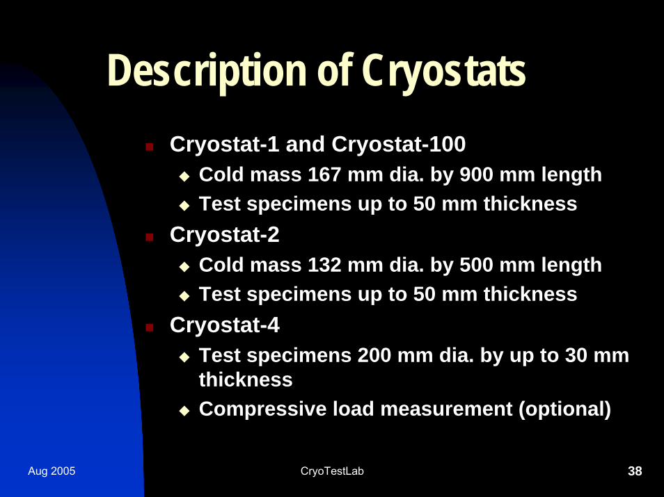
Description of CryostatsCryostat-1 and Cryostat-100
Cold mass 167 mm dia. by 900 mm length Test specimens up to 50 mm thickness
Cryostat-2Cold mass 132 mm dia. by 500 mm lengthTest specimens up to 50 mm thickness
Cryostat-4Test specimens 200 mm dia. by up to 30 mm thicknessCompressive load measurement (optional)
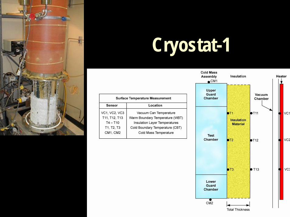
Cryostat-1
Cryostat-2
Cryostat-4
Example Test SeriesCryostat-1
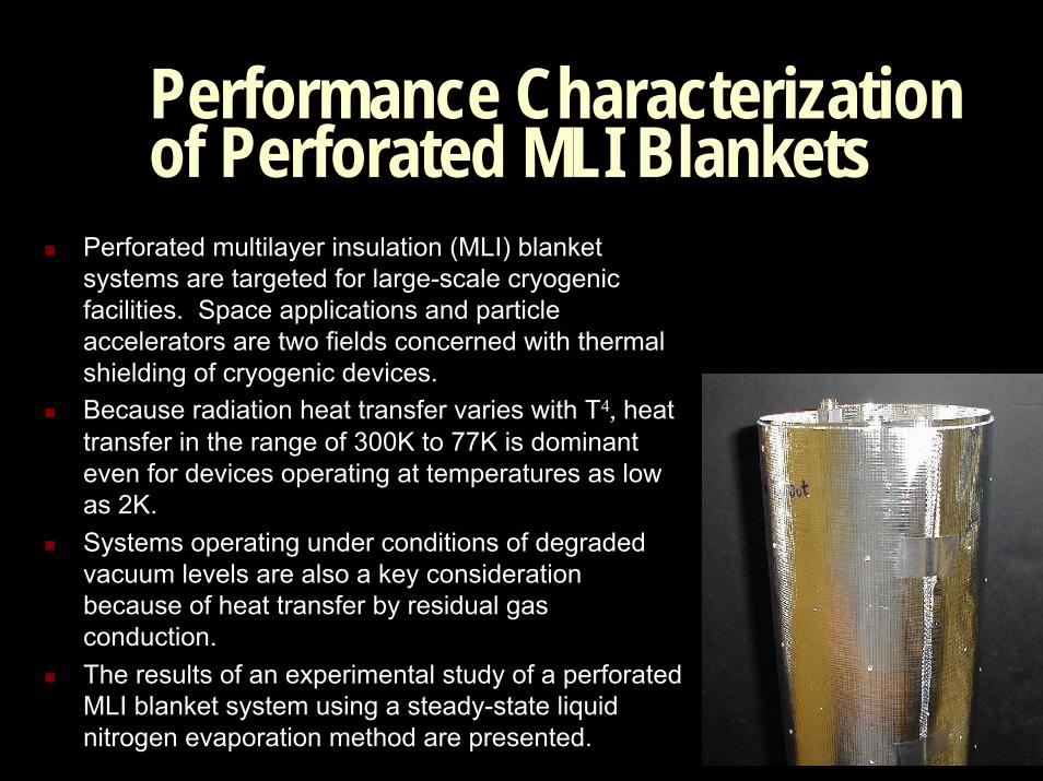
Performance Characterization of Perforated MLI Blankets
Perforated multilayer insulation (MLI) blanket systems are targeted for large-scale cryogenic facilities. Space applications and particle accelerators are two fields concerned with thermal shielding of cryogenic devices. Because radiation heat transfer varies with T4, heat transfer in the range of 300K to 77K is dominant even for devices operating at temperatures as low as 2K. Systems operating under conditions of degraded vacuum levels are also a key consideration because of heat transfer by residual gas conduction. The results of an experimental study of a perforated MLI blanket system using a steady-state liquid nitrogen evaporation method are presented.
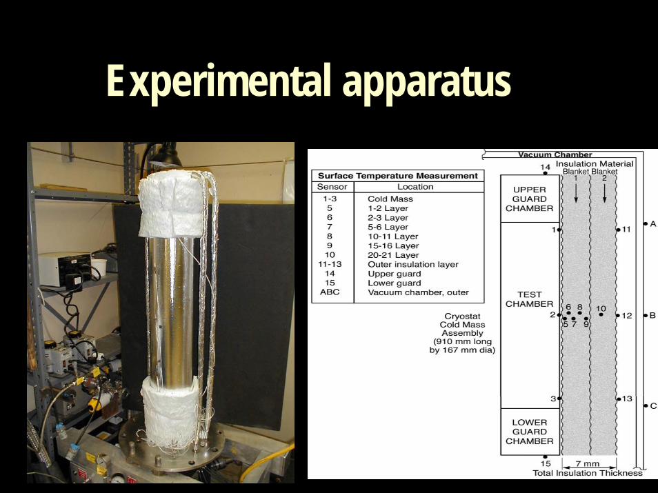
Experimental apparatus
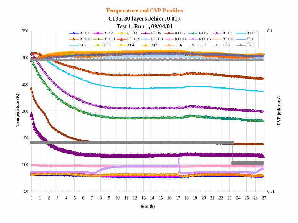
Temperature and CVP ProfilesC135, 30 layers Jehier, 0.01µ
Test 1, Run 1, 09/04/01
50
100
150
200
250
300
350
0 1 2 3 4 5 6 7 8 9 10 11 12 13 14 15 16 17 18 19 20 21 22 23 24 25 26 27
time (h)
Tem
pera
tute
(K)
0.01
0.1
CV
P (m
icro
ns)
RTD1 RTD2 RTD3 RTD5 RTD6 RTD7 RTD8 RTD9RTD10 RTD11 RTD12 RTD13 RTD14 RTD15 RTD16 TC1TC2 TC3 TC4 TC5 TC6 TC7 TC8 CVP1
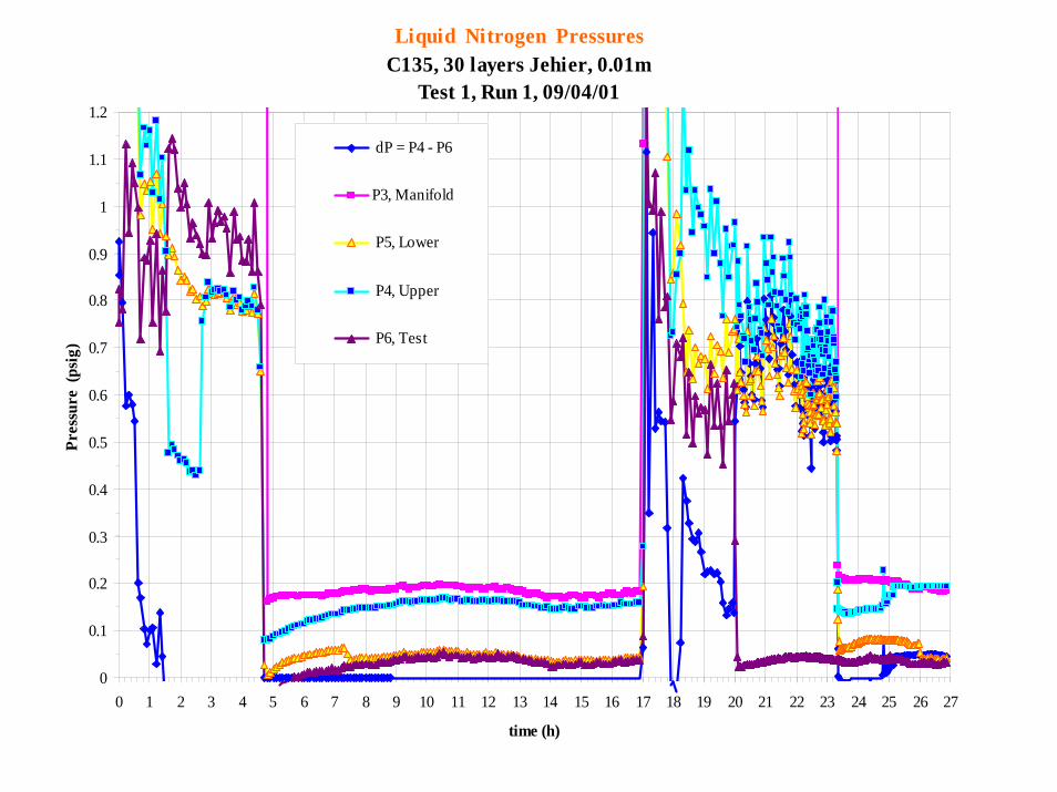
Liquid Nitrogen PressuresC135, 30 layers Jehier, 0.01m
Test 1, Run 1, 09/04/01
0
0.1
0.2
0.3
0.4
0.5
0.6
0.7
0.8
0.9
1
1.1
1.2
0 1 2 3 4 5 6 7 8 9 10 11 12 13 14 15 16 17 18 19 20 21 22 23 24 25 26 27
time (h)
Pres
sure
(ps
ig)
dP = P4 - P6
P3, Manifold
P5, Lower
P4, Upper
P6, Test
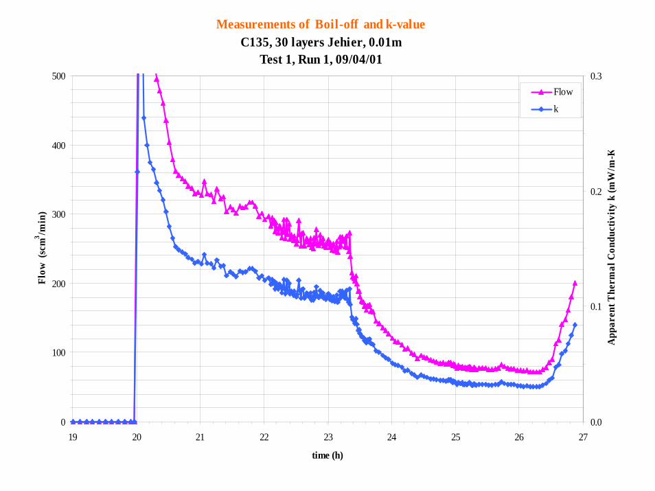
Measurements of Boil-off and k-value C135, 30 layers Jehier, 0.01m
Test 1, Run 1, 09/04/01
0
100
200
300
400
500
19 20 21 22 23 24 25 26 27
time (h)
Flow
(sc
m3 /m
in)
0.0
0.1
0.2
0.3
App
aren
t The
rmal
Con
duct
ivity
k (m
W/m
-K
Flow
k
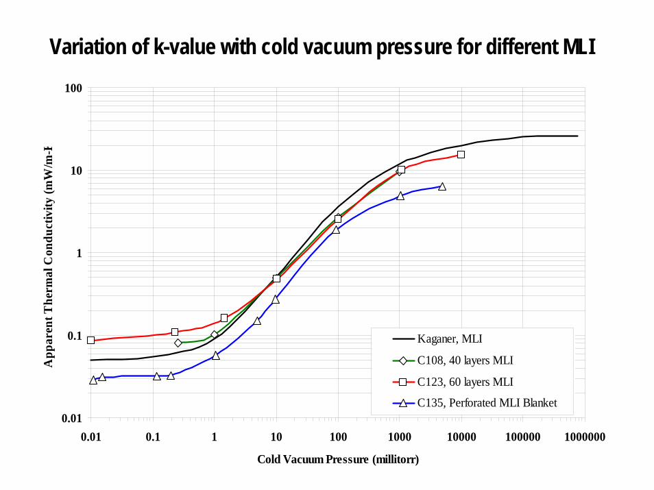
Variation of k-value with cold vacuum pressure for different MLI
0.01
0.1
1
10
100
0.01 0.1 1 10 100 1000 10000 100000 1000000
Cold Vacuum Pressure (millitorr)
App
aren
t The
rmal
Con
duct
ivity
(mW
/m-K
Kaganer, MLI
C108, 40 layers MLI
C123, 60 layers MLI
C135, Perforated MLI Blanket
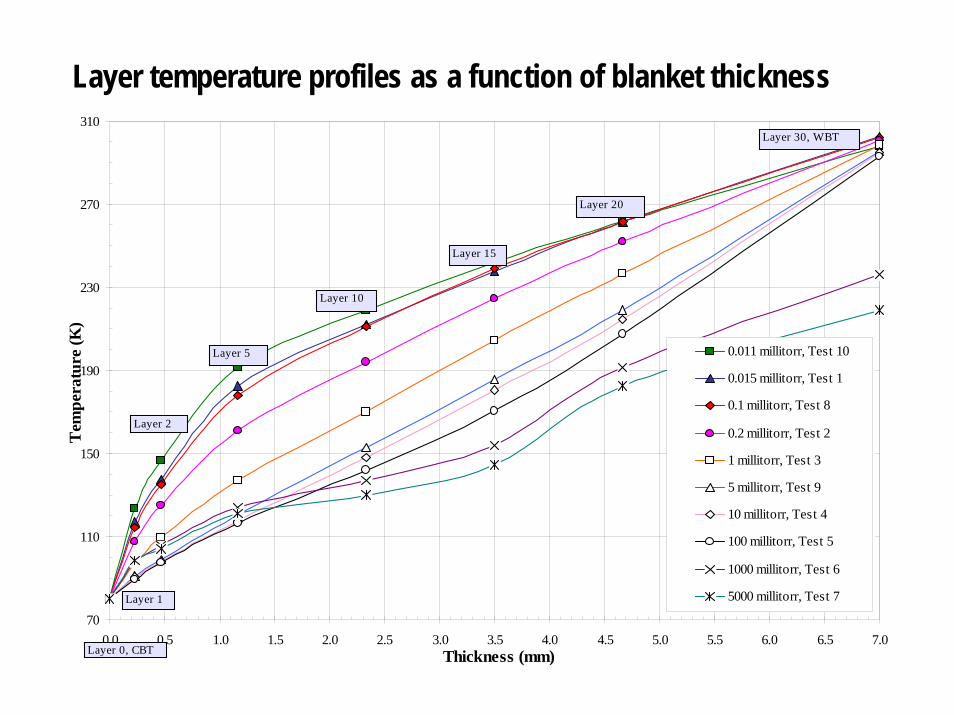
Layer temperature profiles as a function of blanket thickness
70
110
150
190
230
270
310
0.0 0.5 1.0 1.5 2.0 2.5 3.0 3.5 4.0 4.5 5.0 5.5 6.0 6.5 7.0Thickness (mm)
Tem
pera
ture
(K)
0.011 millitorr, Test 10
0.015 millitorr, Test 1
0.1 millitorr, Test 8
0.2 millitorr, Test 2
1 millitorr, Test 3
5 millitorr, Test 9
10 millitorr, Test 4
100 millitorr, Test 5
1000 millitorr, Test 6
5000 millitorr, Test 7
Layer 0, CBT
Layer 2
Layer 1
Layer 30, WBT
Layer 20
Layer 15
Layer 5
Layer 10

PART 3APPLICATIONS
Aug 2005 CryoTestLab 51
Main Categories
High Vacuum (HV)MLI or SI, microfiberglass, fine perlite, LCI, vacuum panels, aerogels
Soft Vacuum (SV)Aerogels, LCI, vacuum panels
No Vacuum (NV)Foams, cellular glass, fiberglass, aerogels

Aug 2005 CryoTestLab 52
Examples
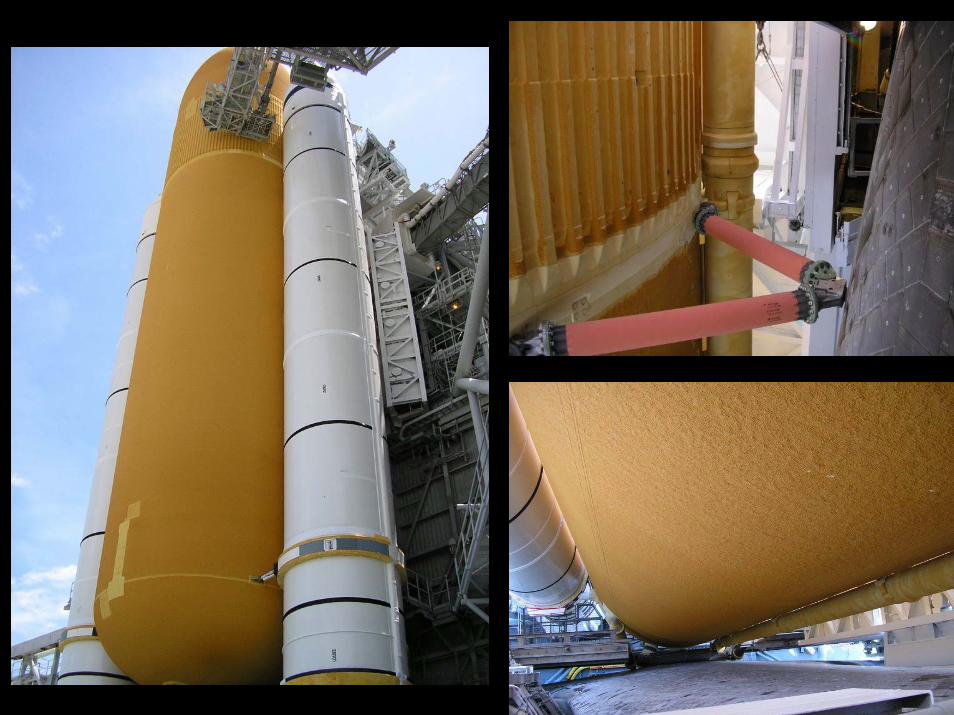
HV: LH2 storage tank, Fuel cell tanks, MLI blanket for Large Hadron Collider (LHC)SV: Piping connections, Mars surface storageNV: Shuttle External Tank, LO2 storage tank
Aug 2005 CryoTestLab 53
New ApplicationsAerogel blankets for next-generation launch vehicle thermal protectionAerogel beads for cold box and non-vacuum applicationsLayered Composite Insulation (LCI), world’s lowest k-value system at soft vacuum levelGlass microspheres for cryogenic tanks and structural applicationsReusable polyimide foams for cryogenic tanks

CONCLUSION
Aug 2005 CryoTestLab 56
There is a hot side and a cold side
The energy WILL balance.We want to make it balance to our best advantage.
Aug 2005 CryoTestLab 57
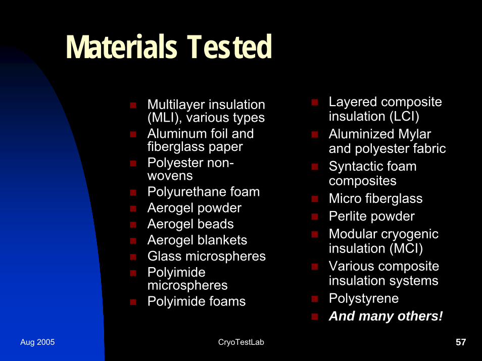
Materials TestedLayered composite insulation (LCI)Aluminized Mylar and polyester fabricSyntactic foam compositesMicro fiberglassPerlite powderModular cryogenic insulation (MCI)Various composite insulation systemsPolystyreneAnd many others!
Multilayer insulation (MLI), various typesAluminum foil and fiberglass paperPolyester non-wovensPolyurethane foamAerogel powderAerogel beadsAerogel blanketsGlass microspheresPolyimide microspheresPolyimide foams
Aug 2005 CryoTestLab 58
Research Testing Conclusion
Well over 1000 cryogenic thermal performance tests of over 100 different thermal insulation systems have been produced by the CryoTestLab at NASA Kennedy Space CenterSpecific insulation systems must be optimized for best performance (such as lowest k-value and bulk density) under different vacuum levelsAll modes of heat transfer (radiation, solid conduction, gas conduction, and convection) must be addressed
Aug 2005 CryoTestLab 59
Significance and ImpactInvented new test equipment and methods for thermal performance characterization of insulation systemsNew standard for testing under actual-use, cryogenic-vacuum conditionsPartnered in development of new products now on the market
Aerogel composite blanket (Aspen Systems)Python vacuum-insulated piping (Chart-MVE)Aerogel beads for thermal insulation (Cabot)
Selected ReferencesFesmire, J. E. and Augustynowicz, S.D., “Improved Thermal-Insulation for Low Temperatures,”NASA Tech Briefs, September 2003, pp. 54-55.Fesmire, J.E., Augustynowicz, S.D., Heckle, K.W., and Scholtens, B.N., “Equipment and Methods for Cryogenic Thermal Insulation Testing,” Cryogenic Engineering Conference, 2003.Fesmire, J.E., and Augustynowicz, S.D, “Thermal Performance Testing of Glass Microspheres under Cryogenic-Vacuum Conditions,” Cryogenic Engineering Conference, 2003.Williams, M., Fesmire, J., Weiser, E., and Augustynowicz, S., “Thermal Conductivity of High Performance Polyimide Foams,” Cold Facts, Cryogenic Society of America, Spring 2002.Fesmire, J. E., Augustynowicz, S.D., and Darve, C., “Performance Characterization of Perforated MLI Blanket,” Proceedings of the Nineteenth International Cryogenic Engineering Conference, ICEC 19, Narosa Publishing House, New Delhi, 2003, pp. 843-846. Fesmire, J.E., Augustynowicz, S.D., and Rouanet, S., “Aerogel Beads as Cryogenic Thermal Insulation System,” in Advances in Cryogenic Engineering, Vol. 47, American Institute of Physics, New York, 2002, pp. 1541-1548.Fesmire, J.E., Augustynowicz, S.D. and Demko, J.A., “Thermal Insulation Performance of Flexible Piping for Use in HTS Power Cables”, in Advances in Cryogenic Engineering, Vol. 47, American Institute of Physics, New York, 2002, pp. 1525-1532.Augustynowicz, S.D. and Fesmire, J.E., “Cryogenic Insulation System for Soft Vacuum,” in Advances in Cryogenic Engineering, Vol. 45, Kluwer Academic/Plenum Publishers, New York, 2000, pp. 1691-1698. Augustynowicz, S.D., Fesmire, J.E., and Wikstrom, J.P., “Cryogenic Insulation Systems,” in 20th
International Congress of Refrigeration Sydney, no. 2000-1147, International Institute of Refrigeration, Paris, 2000. Fesmire, J.E., Rouanet, S., and Ryu, J., “Aerogel-Based Cryogenic Superinsulation,” in Advances in Cryogenic Engineering, Vol. 44, Plenum Press, New York, 1998, pp. 219-226.

CHURCHILL’S COMMENTARY ON MAN:Man will occasionally stumble overthe truth, but most of the time he willpick himself up and continue on