cryohawk half-scale demonstrator of a cresis polar exploration uav concept richard colgren – kuae...
TRANSCRIPT

CryohawkCryohawk
Half-scale Demonstrator of a CReSIS Half-scale Demonstrator of a CReSIS Polar Exploration UAV ConceptPolar Exploration UAV Concept
Richard Colgren – KUAERichard Colgren – KUAE
Meeting 97, Aerospace Control and Guidance Systems CommitteeMeeting 97, Aerospace Control and Guidance Systems Committee
artist’s concept

RoadmapRoadmap
BackgroundBackground Intro to CReSISIntro to CReSIS KU UAV BackgroundKU UAV Background Sensor PayloadSensor Payload RequirementsRequirements Mission ProfileMission Profile Updated DesignUpdated Design
½ Scale ½ Scale DemonstratorDemonstrator AE 721 Student TeamAE 721 Student Team AE 510 Student TeamAE 510 Student Team PSU Team and OthersPSU Team and Others GoalsGoals Current DesignCurrent Design ChallengesChallenges

Intro to CReSISIntro to CReSIS
Science-driven technology developmentScience-driven technology development Focused on mapping ice-sheet Focused on mapping ice-sheet
characteristicscharacteristics Antarctica and Greenland missions in Antarctica and Greenland missions in
years 3 through 5years 3 through 5 Established by NSFEstablished by NSF
For more info, go to cresis.ku.edu
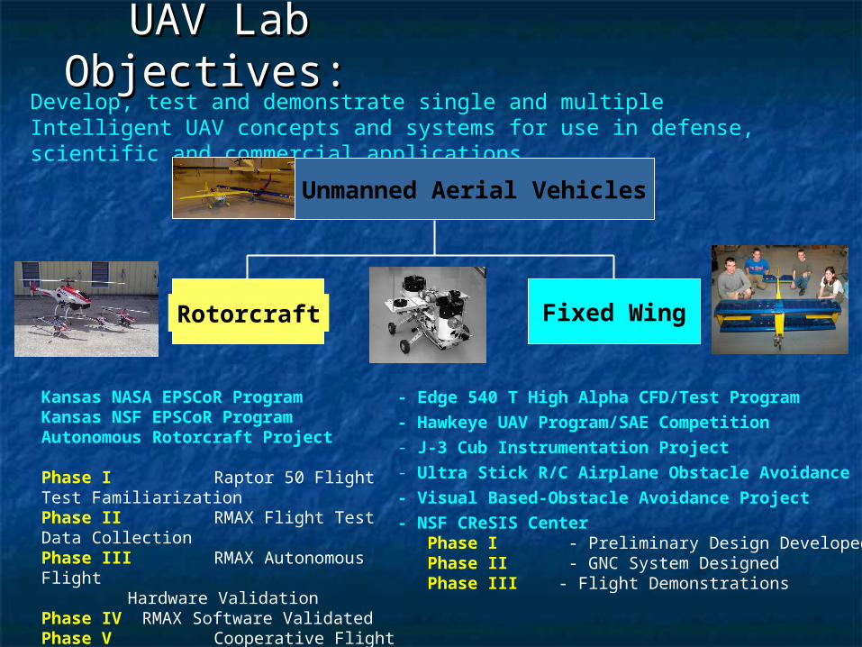
UAV Lab UAV Lab Objectives: Objectives:
Develop, test and demonstrate single and multiple Intelligent UAV concepts and systems for use in defense, scientific and commercial applications.
Unmanned Aerial Vehicles
- Edge 540 T High Alpha CFD/Test Program
- Hawkeye UAV Program/SAE Competition- J-3 Cub Instrumentation Project- Ultra Stick R/C Airplane Obstacle Avoidance
- Visual Based-Obstacle Avoidance Project
- NSF CReSIS Center Phase I - Preliminary Design Developed Phase II - GNC System Designed Phase III - Flight Demonstrations
Kansas NASA EPSCoR ProgramKansas NSF EPSCoR ProgramAutonomous Rotorcraft Project
Phase I Raptor 50 Flight Test FamiliarizationPhase II RMAX Flight Test Data CollectionPhase III RMAX Autonomous Flight
Hardware ValidationPhase IV RMAX Software ValidatedPhase V Cooperative Flight Demonstrated Raptor 50 Leader/Follower, R-Max
Rotorcraft Fixed Wing
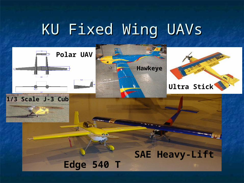
KU Fixed Wing UAVsKU Fixed Wing UAVs
Edge 540 TSAE Heavy-Lift
Polar UAV
1/3 Scale J-3 Cub
Ultra Stick
Hawkeye

KU Rotary Wing UAVsKU Rotary Wing UAVs
Yamaha RMAX and Raptor 50 Helicopters
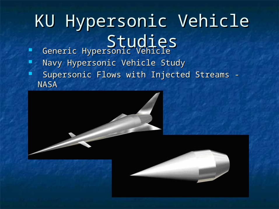
KU Hypersonic Vehicle KU Hypersonic Vehicle StudiesStudies
Generic Hypersonic VehicleGeneric Hypersonic Vehicle Navy Hypersonic Vehicle StudyNavy Hypersonic Vehicle Study Supersonic Flows with Injected Streams - NASASupersonic Flows with Injected Streams - NASA
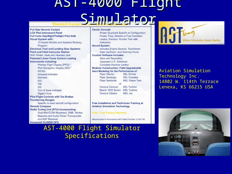
Aviation Simulation Technology Inc.14802 W. 114th TerraceLenexa, KS 66215 USA
AST-4000 Flight Simulator AST-4000 Flight Simulator SpecificationsSpecifications
AST-4000 Flight SimulatorAST-4000 Flight Simulator

KU Hypersonic Vehicle KU Hypersonic Vehicle SimulationSimulation
CCll Versus Versus & Mach & Mach
NumberNumber
521-58-419-
46-318-34-
28-26-
23-6-
4-2-1-l
103.353-M107.419103.803
M106.462-108.964-M102.219
M)(101.044-102.354
M103.794-M)(108.596
10 7.590 - M 10 3.326 10 1.402- C
-0.025001512
-0.023501510
-0.02200158
-0.02050156
-0.01900154
-0.01750152
-0.01600150
-0.030001012
-0.028751010
-0.02750108
-0.02625106
-0.02500104
-0.02375102
-0.02250100
-0.04500612
-0.04375610
-0.0425068
-0.0412566
-0.0400064
-0.0387562
-0.0375060
-0.06400412
-0.06250410
-0.0610048
-0.0595046
-0.0580044
-0.0565042
-0.0550040
ClBM
Look-up table
MATLAB Routine (FITTER)
Original Graph
Analytical Expression
% This routine is written in order to find the best fitting equation for [m,n]=size(A);if(n<4) % For the basic vehicle evaluation, no control surface. newA(:,1:2) = A(:,1:2) ; newA(:,3) = [0] ; newA(:,4) = A(:,3) ; A = newA ;end alpha = A(:,1) ; mach = A(:,2) ; cs = A(:,3) ; val = A(:,4) ; t = size(mach) ; cof = size(27,10) ;%%%%%%%%%%%%%%%%%%%%%%%%%%%%%%%%%%%%%%%%%%%%%%%%%%%%%%%%%%%%%%%%---1st---%%%%%%%%%%%%%%%%%%%%%%%%%%%%%%%%%%%%%%%%%%%%%%%%%%%%%%%%%%%%%%%%%%%%%%%%%%%%%%%%%%%%%%%%%%%%%%%%%% j = 1 ; X = [ones(size(val)) (alpha) (mach) (cs) ] ; % The first prediction for the aerodynamic equation con = X\val ; Cof(1:size(con),j) = con(:) ; newval = X*con ; Err = newval- val ; perf(j) = sse(Err,X) ; % The sum of squares due to error. % This statistic measures the deviation of the responses from the fitted values of the responses. % A value closer to 0 indicates a better fit. % pause%%%%%%%%%%%%%%%%%%%%%%%%%%%%%%%%%%%%%%%%%%%%%%%%%%%%%%%%%%%%%%---2nd---%%%%%%%%%%%%%%%%%%%%%%%%%%%%%%%%%%%%%%%%%%%%%%%%%%%%%%%%%%%%%%%%%%%%%%%%%%%%%%%%%%%%%%%%%%%%%%%%%% j = j+1 ; X = [ones(size(val)) (alpha) (mach) (cs) (alpha).^2 (mach).^2 (cs).^2 ] ; % The 2nd prediction for the aerodynamic equation con = X\val ; Cof(1:size(con),j) = con(:) ; newval = X*con ;
MATLAB Simulation FORTRAN Simulation
Trajectory
0
20000
40000
60000
80000
100000
120000
0 5 10 15 20 25
Mach Number
Alt
itu
de Accent
Level flight
Descent
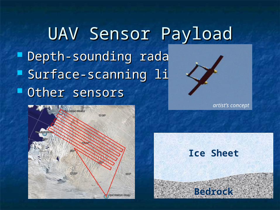
UAV Sensor PayloadUAV Sensor Payload Depth-sounding radarDepth-sounding radar Surface-scanning lidarSurface-scanning lidar Other sensorsOther sensors
Bedrock
Ice Sheet
artist’s concept
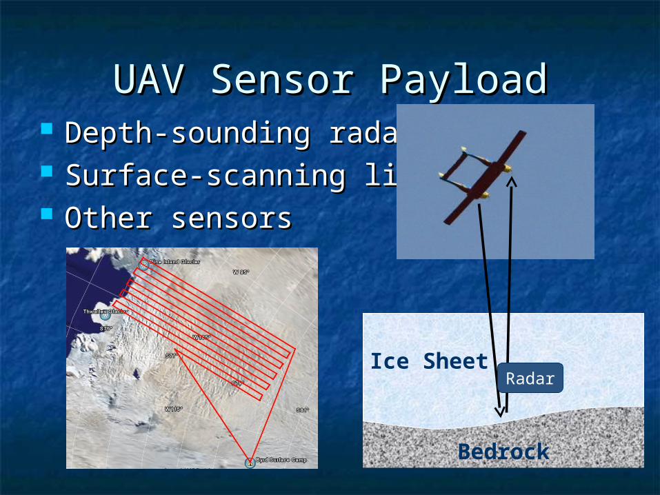
UAV Sensor PayloadUAV Sensor Payload Depth-sounding radarDepth-sounding radar Surface-scanning lidarSurface-scanning lidar Other sensorsOther sensors
Bedrock
Ice SheetRadar

UAV Sensor PayloadUAV Sensor Payload Depth-sounding radarDepth-sounding radar Surface-scanning lidarSurface-scanning lidar Other sensorsOther sensors
Bedrock
Ice SheetRadar
Lidar

UAV RequirementsUAV Requirements
175 lb payload175 lb payload Radar antenna array (14 ft by 2.5 ft)Radar antenna array (14 ft by 2.5 ft) 6,000 km (3,200 nm) round trip6,000 km (3,200 nm) round trip 1 km (3,300 ft) AGL for survey1 km (3,300 ft) AGL for survey 126 knots for survey (155 knots 126 knots for survey (155 knots
cruise)cruise) Jet or Diesel fuel preferredJet or Diesel fuel preferred

Mission Profile (Greenland)Mission Profile (Greenland)
Taxi / takeoff / climbTaxi / takeoff / climb Cruise 200 nm to glacierCruise 200 nm to glacier Conduct surveyConduct survey
Local surveyLocal surveyoror
Regional survey Regional survey Return cruise to baseReturn cruise to base Land / taxiLand / taxi

Mission 1 Profile (Antarctica)Mission 1 Profile (Antarctica)
Taxi / takeoff / climbTaxi / takeoff / climb Cruise 1,350 nmCruise 1,350 nm Conduct surveyConduct survey
Local surveyLocal surveyoror
Regional surveyRegional survey Return cruiseReturn cruise Land / taxiLand / taxi
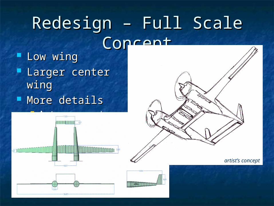
Redesign – Full Scale Redesign – Full Scale ConceptConcept
Low wingLow wing Larger center wingLarger center wing More detailsMore details
Antennas, etc.Antennas, etc.
artist’s concept
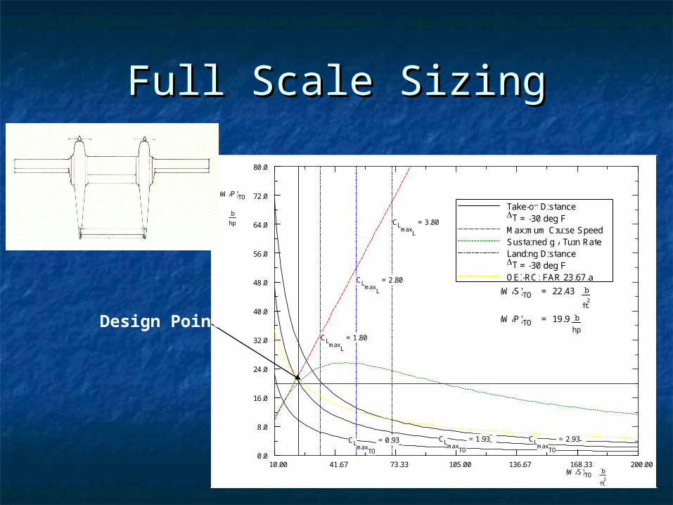
Full Scale SizingFull Scale Sizing
(W/S)TO = 22.43 lb
ft2
(W/P)TO = 19.9 lbhp
(W/S)TOlb
ft2
(W/P)TO
lb
hp
10.00 41.67 73.33 105.00 136.67 168.33 200.00
80.0
72.0
64.0
56.0
48.0
40.0
32.0
24.0
16.0
8.0
0.0
CLmax
L
= 1.80
CLmax
L
= 2.80
CLmax
L
= 3.80
CLmax
TO
= 0.93 CLmax
TO
= 1.93 CLmax
TO
= 2.93
Take-off Distance T = -30 deg FMaximum Cruise Speed Sustained g / Turn Rate Landing Distance T = -30 deg FOEI-RC: FAR 23.67.a
Design Point

Revised DesignRevised Design Take-off gross weightTake-off gross weight 2,806 lbs2,806 lbs Empty weightEmpty weight 1,552 lbs1,552 lbs Fuel weightFuel weight 1,064 lbs1,064 lbs

Regression Study of 18 Regression Study of 18 UAVsUAVs
Design

Engine Power EstimationEngine Power Estimation
Wing loading = 22 lb/ftWing loading = 22 lb/ft22 Power loading = 19 lb/hpPower loading = 19 lb/hp
Total Power Required = 2806/19 Total Power Required = 2806/19 150 hp150 hp
Power Required per engine = 75 hpPower Required per engine = 75 hp
½ Scale to use two 3W-75 engines½ Scale to use two 3W-75 engines

Graduate Design-Build-Fly Graduate Design-Build-Fly TeamTeam
Four students:Four students: David BorysDavid Borys Satish ChilakalaSatish Chilakala Edmond LeongEdmond Leong Nelson BrownNelson Brown
Advisors:Advisors: Dr. Richard ColgrenDr. Richard Colgren Jewon Lee (TA)Jewon Lee (TA)

CollaborationCollaboration
Undergrad manufacturing class Undergrad manufacturing class (AE510)(AE510) Center wingCenter wing
Pittsburg State UniversityPittsburg State University Water-jet cuttingWater-jet cutting TemplatesTemplates
Kansas State UniversityKansas State University AutopilotAutopilot
You?You?

GoalsGoals Stability and control demonstrator for Stability and control demonstrator for
CReSISCReSIS Experience for KUAEExperience for KUAE
Manufacturing larger aircraftManufacturing larger aircraft Operating sizable UAVsOperating sizable UAVs
Asset for ongoing Asset for ongoing
UAV researchUAV research
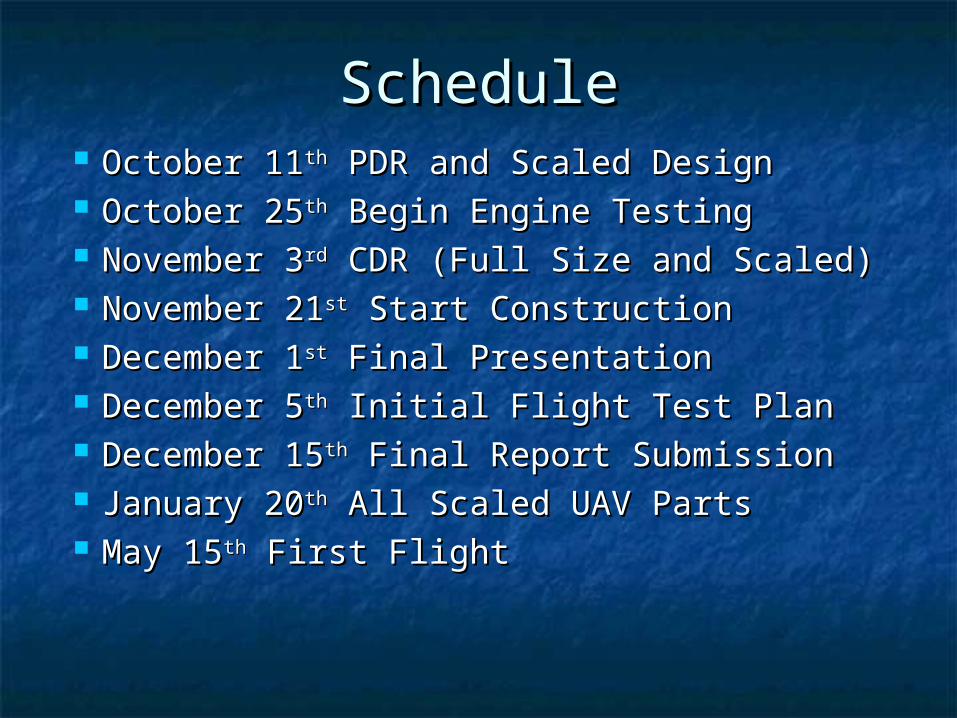
ScheduleSchedule October 11October 11thth PDR and Scaled Design PDR and Scaled Design October 25October 25thth Begin Engine Testing Begin Engine Testing November 3November 3rdrd CDR (Full Size and Scaled) CDR (Full Size and Scaled) November 21November 21stst Start Construction Start Construction December 1December 1stst Final Presentation Final Presentation December 5December 5thth Initial Flight Test Plan Initial Flight Test Plan December 15December 15thth Final Report Submission Final Report Submission January 20January 20thth All Scaled UAV Parts All Scaled UAV Parts May 15May 15thth First Flight First Flight
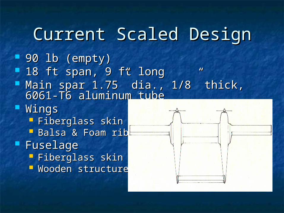
Current Scaled DesignCurrent Scaled Design 90 lb (empty)90 lb (empty) 18 ft span, 9 ft long18 ft span, 9 ft long Main spar 1.75” dia., 1/8” thick, 6061-T6 Main spar 1.75” dia., 1/8” thick, 6061-T6
aluminum tubealuminum tube WingsWings
Fiberglass skinFiberglass skin Balsa & Foam ribsBalsa & Foam ribs
FuselageFuselage Fiberglass skinFiberglass skin Wooden structureWooden structure

Building the CryohawkBuilding the Cryohawk

ParticipationParticipation
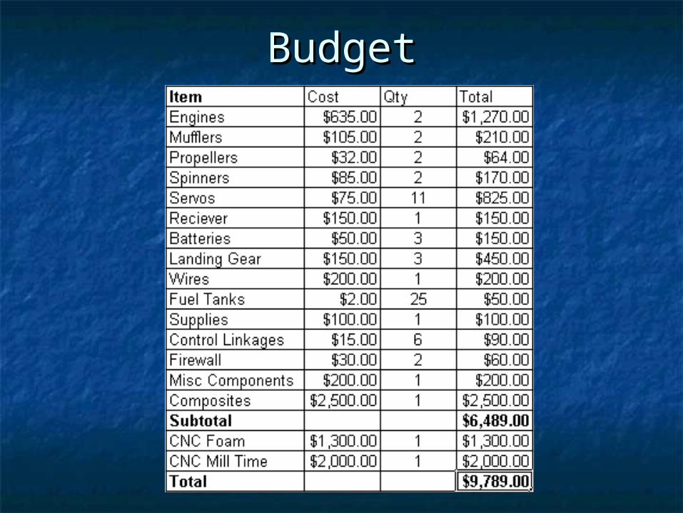
BudgetBudget
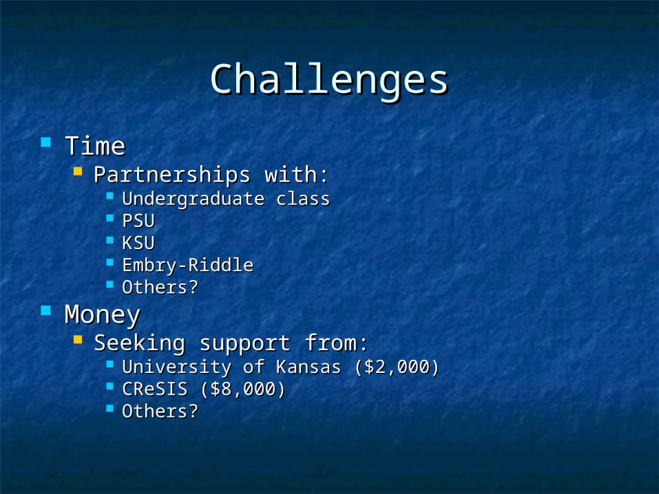
ChallengesChallenges TimeTime
Partnerships with:Partnerships with: Undergraduate classUndergraduate class PSUPSU KSUKSU Embry-RiddleEmbry-Riddle Others?Others?
MoneyMoney Seeking support from:Seeking support from:
University of Kansas ($2,000)University of Kansas ($2,000) CReSIS ($8,000)CReSIS ($8,000) Others?Others?
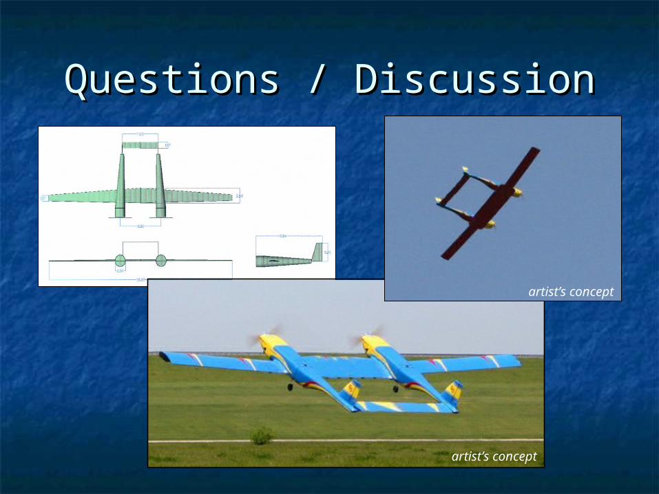
Questions / DiscussionQuestions / Discussion
artist’s concept
artist’s concept