cs-3 · 2017-06-16 · foreword vii cs-3 manual - part # 762701 revision 4.0 foreword the cs-3 is...
TRANSCRIPT

OPERATION MANUAL
CS-3Scintrex Cesium Vapor Magnetometer Sensor
SCINTREX
CS-3 Manual - part # 762701 Revision 4.0
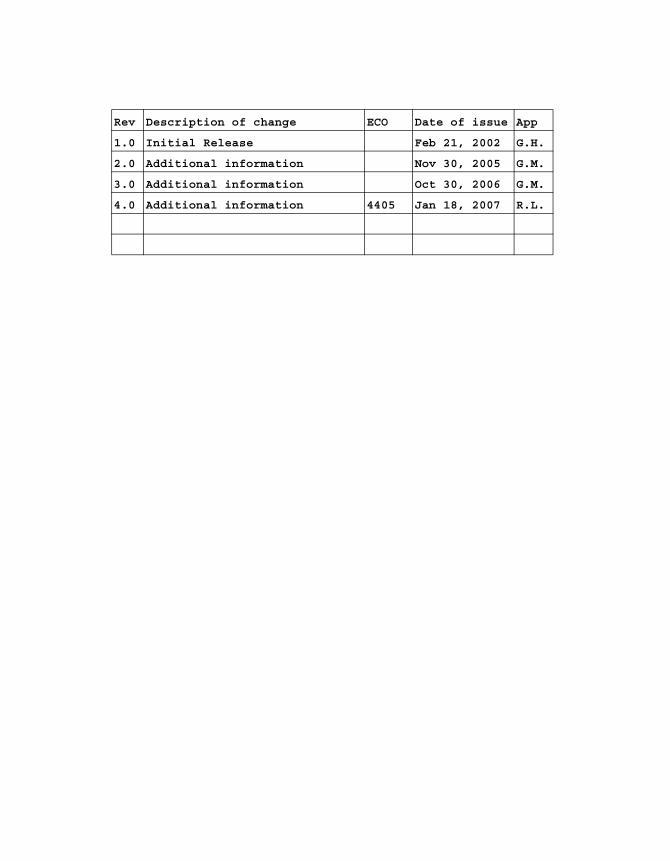
Rev Description of change ECO Date of issue App
1.0 Initial Release Feb 21, 2002 G.H.
2.0 Additional information Nov 30, 2005 G.M.
3.0 Additional information Oct 30, 2006 G.M.
4.0 Additional information 4405 Jan 18, 2007 R.L.
Operation Manual
CS-3Scintrex Cesium Vapor Magnetometer Sensor
CS-3 Manual - part # 762701 Revision 4.0
SCINTREX LIMITED
World-wide web: http://www.scintrexltd.com
Copyright © SCINTREX Limited 2005. All rights reserved.
No part of this publication may be reproduced, stored in a retrieval system or transmitted, in any form, or by any means, electronic, mechanical, photo-copying, recording, or otherwise, without prior consent from SCINTREX Limited.
Document Part No. 762701, Revision 3.0
Printed and bound in Canada
HEAD OFFICESCINTREX Limited
222 Snidercroft Road
Unit #1
Concord, Ontario
Canada, L4K 2K1
tel: +1 905 669 2280
fax: +1 905 669 6403
e-mail: [email protected]
CS-3 Manual - part # 762701 Revision 4.0
Tab
le of C
on
tents
2nd
2
2nd Draft
Foreword
Getting StartedAbout this manual . . . . . . . . . . . . . . . . . . . . . . . . . . . . . . . . . . . . . . . . . . . . . . . . . . .
Page Numbering . . . . . . . . . . . . . . . . . . . . . . . . . . . . . . . . . . . . . . . . . . . . . . . . .
Type Styles . . . . . . . . . . . . . . . . . . . . . . . . . . . . . . . . . . . . . . . . . . . . . . . . . . . . .Chapter Layout . . . . . . . . . . . . . . . . . . . . . . . . . . . . . . . . . . . . . . . . . . . . . . . . . .Symbols . . . . . . . . . . . . . . . . . . . . . . . . . . . . . . . . . . . . . . . . . . . . . . . . . . . . . . .
Understanding Instrument Basics . . . . . . . . . . . . . . . . . . . . . . . . . . . . . . . . . . . . . .Sensor Head . . . . . . . . . . . . . . . . . . . . . . . . . . . . . . . . . . . . . . . . . . . . . . . . . . . .Sensor Electronics . . . . . . . . . . . . . . . . . . . . . . . . . . . . . . . . . . . . . . . . . . . . . . .
Old version . . . . . . . . . . . . . . . . . . . . . . . . . . . . . . . . . . . . . . . . . . . . . . . . . . . . .New version . . . . . . . . . . . . . . . . . . . . . . . . . . . . . . . . . . . . . . . . . . . . . . . . . . . .
Operating the CS-3 in the FieldSetting Up the CS-3 . . . . . . . . . . . . . . . . . . . . . . . . . . . . . . . . . . . . . . . . . . . . . . . . . .
Mounting the CS-3 . . . . . . . . . . . . . . . . . . . . . . . . . . . . . . . . . . . . . . . . . . . . . . .
Powering Up . . . . . . . . . . . . . . . . . . . . . . . . . . . . . . . . . . . . . . . . . . . . . . . . . . . .Obtaining the Larmor Signal . . . . . . . . . . . . . . . . . . . . . . . . . . . . . . . . . . . . . . . . . . .Setting the Operating Hemisphere . . . . . . . . . . . . . . . . . . . . . . . . . . . . . . . . . . . . . .Operating in the Presence of Spurious Magnetic Fields . . . . . . . . . . . . . . . . . . . .
Orienting Your CS-3Understanding the Active Zone of the CS-3 . . . . . . . . . . . . . . . . . . . . . . . . . . . .Using a Strapped Down CS-3 for Surveys . . . . . . . . . . . . . . . . . . . . . . . . . . . . .Calculating the Tumble Angle . . . . . . . . . . . . . . . . . . . . . . . . . . . . . . . . . . . . . . .
Recommended Survey Orientations . . . . . . . . . . . . . . . . . . . . . . . . . . . . . . . . . .Comparison with the Locked Oscillator. . . . . . . . . . . . . . . . . . . . . . . . . . . . . . . .
Maintaining Your CS-3 and Trouble-shootingTrouble-shooting . . . . . . . . . . . . . . . . . . . . . . . . . . . . . . . . . . . . . . . . . . . . . . . . . . . .
Reference InformationCS-3 Technical Specifications. . . . . . . . . . . . . . . . . . . . . . . . . . . . . . . . . . . . . . . . . .Instrument Parts List . . . . . . . . . . . . . . . . . . . . . . . . . . . . . . . . . . . . . . . . . . . . . . . . .
CS-3 Standard Accessories . . . . . . . . . . . . . . . . . . . . . . . . . . . . . . . . . . . . . . . .Warranty and Repair. . . . . . . . . . . . . . . . . . . . . . . . . . . . . . . . . . . . . . . . . . . . . . . . . .
Warranty . . . . . . . . . . . . . . . . . . . . . . . . . . . . . . . . . . . . . . . . . . . . . . . . . . . . . . .
Repair . . . . . . . . . . . . . . . . . . . . . . . . . . . . . . . . . . . . . . . . . . . . . . . . . . . . . . . . .
. . 1-1 . . 1-1
. . 1-2 . . 1-3 . . 1-4
. . 1-5 . . 1-5 . . 1-7
. . 1-9 . . 1-9
. . 2-2 . . 2-3
. . 2-4 . . 2-5 . . 2-7 . . 2-9
. . 3-2 . . 3-7 . . 3-7
. 3-18 . 3-20
. . 4-2
. . 5-1 . . 5-3 . . 5-3 . . 5-3 . . 5-3
. . 5-4
vCS-3 Manual - part # 762701 Revision 4.0

Shipping Instructions . . . . . . . . . . . . . . . . . . . . . . . . . . . . . . . . . . . . . . . . . . . . . . . . 5-4
Appendix A: Theory of OperationSystem Overview. . . . . . . . . . . . . . . . . . . . . . . . . . . . . . . . . . . . . . . . . . . . . . . . . . . A-1
Appendix B: CS-3 Block Diagram
CS-3 Manual - part # 762701 Revision 4.0
vi

Fo
rewo
rd
Foreword
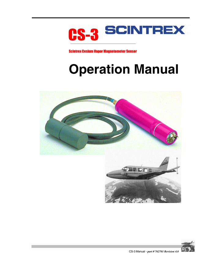
The CS-3 is an optically pumped cesium vapor magnetometer sensor used for scalar measurement of the Earth's magnetic field. As shown below, the CS-3 sensor consists of a sensor head with cable and sensor electronics.
Figure 1: CS-3 Magnetometer Sensor
The system excels in a variety of applications (ex. airborne, satellite, marine and ground magnetometry or gradiometry, base station magnetometry and ferrous ordnance location) due to its:
• high sensitivity
• high cycling rates
• excellent gradient tolerance
• continuous output
• automatic hemisphere switching
viiCS-3 Manual - part # 762701 Revision 4.0

• fast response
• low susceptibility to the electromagnetic interference
Magnetic field measurements performed by the CS-3 is based on quantum mechanics principles, and the phenomena of optical pumping and self-oscillation. When properly oriented in relation to the ambient magnetic field, cesium vapor in the sensor oscillates continuously by itself without any assistance. The frequency of oscillation (defined as the Larmor frequency) is proportional to the ambient magnetic field.
The sensor outputs a signal at the Larmor frequency which is normally processed by an external magnetometer processor linked to the system. The magnetometer processor converts the Larmor frequency into digital magnetic field readings and presents them for display and recording. Modern magnetic processors have a resolution of 0.001 nT and read 10 times each second or faster.
In summary, the CS-3 offers distinct and substantial benefits in measurement of magnetic fields due to the principles of both optical pumping and self-oscillation. These advantages are described in the next two sections.
Advantages of Optical PumpingThese benefits are shared by all well designed optically pumped magnetometers regardless of which atoms (cesium, rubidium, potassium or helium) are being pumped, and regardless which of two principles of operation is utilized (self oscillation, or locked oscillation).
High Sensitivity
Due to the narrow resonant linewidth and good signal to noise ratio the sensitivity of optically pumped magnetometers is in the range of few pT (1pT=0.001nT) in the measuring bandwidth of 1Hz. In contrast to the proton precession magnetometers, the sensitivity does not deteriorate as the measured ambient field decreases.
Continuous Signal
The operation of the optically pumped magnetometers is not cyclic. Highly sensitive readings could be obtained at the high repetition rate.
CS-3 Manual - part # 762701 Revision 4.0
viii
Fo
rewo
rd
2nd
2
2nd Draft
High Gradient Tolerance
Absorption cells of the optically pumped magnetometers in which the detection of the ambient field is taking place are normally much smaller than the sensors of proton precession (including Overhauser) magnetometers. Consequently, the field gradients over the sensor volume are much smaller and the proper operation of the magnetometer is much less affected, e.g. the volume of the CS-3 absorption cell is only 0.006 liters.
Low Radiated Electromagnetic Interference
Sensors of the optically pumped magnetometers radiate low disturbing EM fields. The H1 field is the order of 10 nT. The RF field for the lamp excitation is well confined and of the high frequency - around 165 MHz for the CS-3.
Insensitivity to Motion Induced Doppler Effects
Irregular motion of the platform carrying the sensor modulates (adds to) the precession frequency and introduces noise into the measurements of the magnetic field.
Proton precession (including Overhauser) magnetometers are affected to a much greater degree by motion noise due to much lower gyromagnetic constant, e.g. in the ambient magnetic field of 50,000nT the Larmor frequency of the CS-3 is 175,000Hz, which is 82 times larger than 2100Hz, the precession frequency of the proton magnetometer.
Advantages of Self OscillationUse of the self-oscillating principle of operation results in the following additional benefits not available from optically pumped magnetometers using locked oscillator principle of operation:
Fast Start-up
If the sensor head is properly oriented inside its active operating zone, the CS-3 will start oscillating shortly after it is turned on. The warm-up time is determined by the time required for the electronically controlled heaters to bring the absorption cell and the cesium lamp to the proper operating temperature.
ixCS-3 Manual - part # 762701 Revision 4.0

The warm-up is over in few minutes after a cold start. However, if the operating temperature is already established, it takes only few milliseconds for the magnetometer to start oscillating after a turn on or after an orientation change from a dead zone into the active zone.
In contrast, a locked oscillator magnetometer invariably contains a voltage controlled oscillator (VCO), whose frequency in normal operation is forced (locked) by the control electronics to follow the resonant Larmor frequency.
However, at every start-up, cold or warm, before the locking is acquired, the VCO frequency has to be swept relatively slowly until it comes close enough to the Larmor frequency. Then the locking takes place and the magnetometer becomes operational.
Note that the Larmor frequency is known beforehand only coarsely and consequently this search process takes several seconds. The same search procedure takes place if the lock is lost because of a fast field change or a disturbing AC magnetic field.
Fast Response and Tracking
The response of a self-oscillating magnetometer to the magnetic field changes is extremely fast. It has been experimentally determined that the Larmor frequency precisely changed in response to the step changes of several thousand nT within a Larmor period. Equally, the magnetometer followed sinusoidal field changes of the amplitude of hundreds nT at the rate of several kHz without appreciable lag in response.
In contrast, the rate of ambient field change, which a locked oscillator magnetometer could follow without losing lock, is much smaller. In addition, spurious fields, either AC (50-400Hz) or pulsed, in the range of several hundred nT cause the magnetometer to lose lock.
Low Susceptibility to Electromagnetic Fields
The susceptibility to spurious EM fields depends very much on the principle of operation. Most widely encountered spurious fields originate from the power lines and the airborne geophysical EM systems, and are in the frequency range of 50Hz to several thousand Hz. In general, the susceptibility increases greatly as the frequency of the interfering field approaches the operating (Larmor, proton precession) frequency.
Proton precession magnetometers (including Overhauser) have low susceptibility for two reasons:
• they use induction coils to detected proton precession
CS-3 Manual - part # 762701 Revision 4.0
x

Fo
rewo
rd
2nd
2
2nd Draft
• the interfering EM field are normally at the frequencies close to the proton precession frequency.
Neither of above liabilities apply for optically pumped magnetometers because:
• signal detection is optical
• the interfering frequencies are normally far from the Larmor frequency.
In addition, the susceptibility of the self-oscillating magnetometer is low, because its feedback loop is very simple and fast, allowing it to respond with little lag to the fast changing fields.
In contrast, the locked oscillator response is much slower because its control loop frequency bandwidth is limited to few hundred Hz. Furthermore, the feedback control is achieved by monitoring a modulating signal, which frequency is in the range of one hundred Hz, and which detection could be readily upset by the interfering EM fields.
For either of above reasons, the locked oscillator may lose lock and become temporary non-functional for few seconds in presence of a spurious EM field.
Superior Worldwide Orienting Capabilities
The analysis presented in Chapter 3, “Orienting Your CS-3” proves that, contrary to the widely accepted belief, a well designed self-oscillating magnetometer is as easy to orient as the locked oscillator. Even more important, it offers wider safety margins to the boundaries of operating zone, than the locked oscillator.
xiCS-3 Manual - part # 762701 Revision 4.0

CS-3 Manual - part # 762701 Revision 4.0
xii

Startu
p
1 Getting Started
About this manual
Page NumberingThe numbering scheme used consists of two parts: the chapter number and page number. For example, 3-1 would refer to chapter 3, page 1.
For your convenience, each chapter has a thumb-tab on the right-hand side allowing you to quickly locate a chapter of interest. The thumb-tabs are arranged in descending order, with Chapter 1 always starting at the top.
1-1CS-3 Manual - part # 762701 Revision 4.0

Getting Started
Type StylesThe following typeface conventions will be used throughout the manual.
Convention Use
Bold Italic Indicates an action to be taken
Italic Denotes a new term being introduced
ALL CAPS Denotes the name of a screen, key or mode (function)
CS-3 Manual - part # 762701 Revision 4.0
1- 2
About this manual
Startu
p
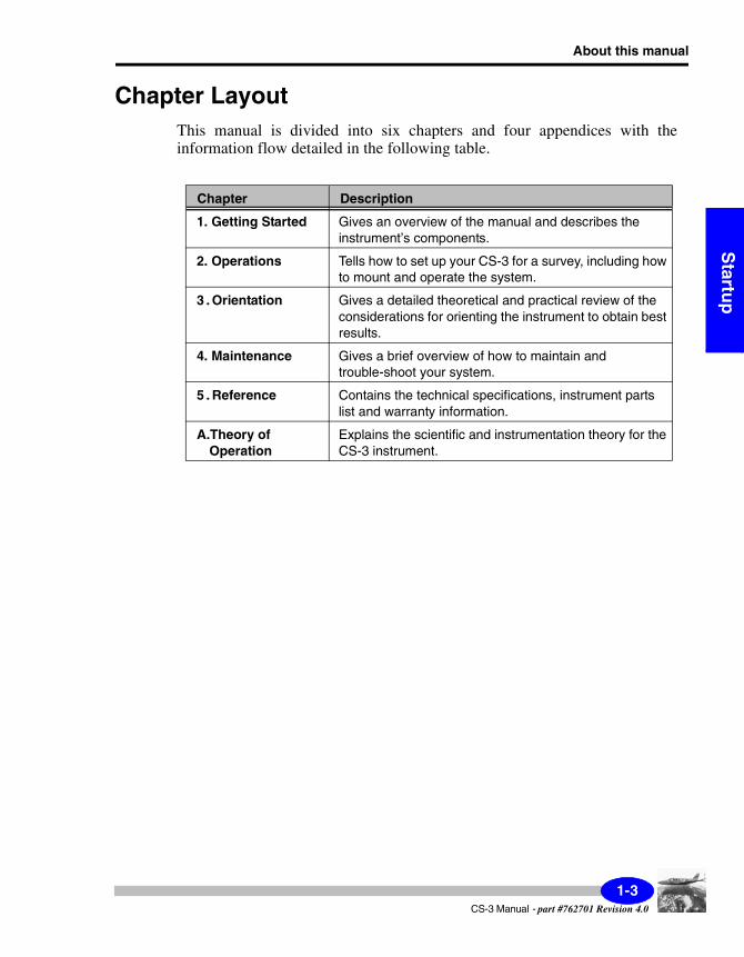
Chapter LayoutThis manual is divided into six chapters and four appendices with the information flow detailed in the following table.
Chapter Description
1. Getting Started Gives an overview of the manual and describes the instrument’s components.
2. Operations Tells how to set up your CS-3 for a survey, including how to mount and operate the system.
3.Orientation Gives a detailed theoretical and practical review of the considerations for orienting the instrument to obtain best results.
4. Maintenance Gives a brief overview of how to maintain and trouble-shoot your system.
5.Reference Contains the technical specifications, instrument parts list and warranty information.
A.Theory of Operation
Explains the scientific and instrumentation theory for the CS-3 instrument.
1-3CS-3 Manual - part #762701 Revision 4.0
Getting Started
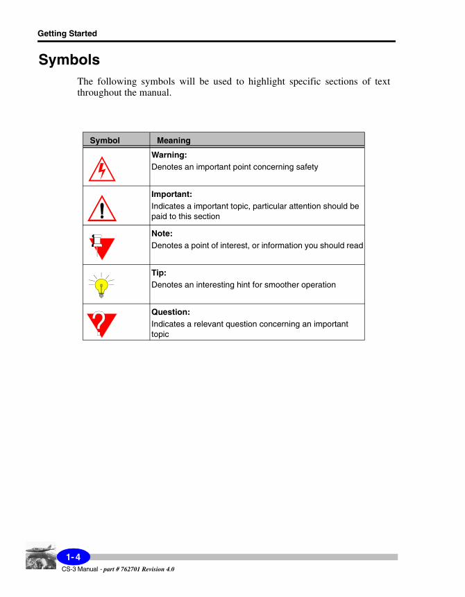
SymbolsThe following symbols will be used to highlight specific sections of text throughout the manual.
Symbol Meaning
Warning:Denotes an important point concerning safety
Important:Indicates a important topic, particular attention should be paid to this section
Note:Denotes a point of interest, or information you should read
Tip:Denotes an interesting hint for smoother operation
Question:Indicates a relevant question concerning an important topic
CS-3 Manual - part # 762701 Revision 4.0
1- 4

Understanding Instrument Basics
Startu
p
Understanding Instrument BasicsThe CS-3 Magnetometer Sensor consists of a sensor head and sensor electronics that are interconnected by a cable. This section provides schematics and descriptions for each of these components and their subsystems.
Sensor HeadThe sensor head houses electro-optical detection system. All the parts of the sensor head, including the outside plastic housing, are made of carefully screened nonmagnetic materials. The following figure shows a schematic of the sensor head.
Figure 2 - Schematic of the sensor head
3
1-5CS-3 Manual - part #762701 Revision 4.0
Getting Started
Important:
To minimize the static magnetic interference from the electronic components which are slightly magnetic, the sensor head should be kept away from the electronics assembly by the full cable length.
The actual measurement of the ambient magnetic field takes place inside the absorption cell which has diameter 22mm, and the length 25mm. The position of the cell's centre is marked by a narrow groove, machined on the outside of the plastic cylindrical housing. The adjacent wider grove is provided to facilitate secure grip for the mounting clamps.
The interconnecting cable exits at the right angle on the top end of the sensor head. For properly orienting the sensor head as described in Chapter 3, “Orienting Your CS-3”, it is important to know the direction of the optical axis. In Figure 1 on page vii, the direction of the optical axis is depicted in relation to the outside mechanical features of the sensor head.
The sensor head housing provides an air/water tight enclosure for the sensor components, and it should not be opened. In addition, critical optical components inside the sensor head are carefully aligned in order to minimize the orientation errors, and opening the sensor head by unqualified people may upset the alignment.
CS-3 Manual - part # 762701 Revision 4.0
1- 6

Understanding Instrument Basics
Startu
p
Sensor ElectronicsThe sensor electronics are housed in a cylindrical container as shown in the following schematic.
Figure 3 - Schematic of the electronics housing
The electronics consist of three major subsystems:
• Larmor amplifier
• Lamp and absorption cell heaters
• RF lamp exciter
The RF exciter generates few watts of RF power at the frequency of about 165MHz. In order to keep the radiated electromagnetic interference low, the exciter is located inside a metallic enclosure. In addition, all the sensor electronic systems are enclosed inside a cylindrical, metal box.
Electronic Housing
Internally, the sensor electronic housing is connected to the negative line of the input supply voltage. If the negative side of the power supply, which provides the power for the CS-3, is grounded to the frame of the vehicle, and if the electronic box of the CS-3 makes an electrical contact to the same frame, then the return current could flow partially through the frame instead of being confined to the return line inside the supply cable.
CS-3 ELECTRONIC HOUSING
1-7CS-3 Manual - part #762701 Revision 4.0
Getting Started
The stray magnetic field created by this current could corrupt the measurement of the ambient field. To prevent that happening, the outside of the electronics box is covered with a thin, plastic insulating sleeve.
Important:
Please, make sure that this plastic sleeve is not damaged to such an extent that the metal part of the CS-3 electronics housing is making contact to a metal part of the airplane or vehicle frame.
The sensor head connector is mounted on one side panel of the electronic box. On the opposite side, following components are mounted on the control panel, see Figure 4.
Hemisphere Control Switch
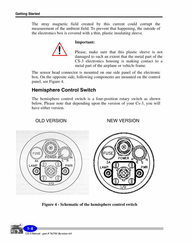
The hemisphere control switch is a four-position rotary switch as shown below. Please note that depending upon the version of your Cs-3, you will have either version.
Figure 4 - Schematic of the hemisphere control switch
OLD VERSION NEW VERSION
CS-3 Manual - part # 762701 Revision 4.0
1- 8
Understanding Instrument Basics
Startu
p
Old versionThe swich settings perform the following functions:
N - Manually sets the CS-3 to operate in northern operating hemisphere.
S - Manually sets the CS-3 to operate in southern operating hemisphere.
L - Local setting allows the operation of the CS-3 to be controlled by the TTL voltage level at the pin D of the four pin connector (pin A is ground): open circuited or high level voltage for operation in southern hemisphere, low level voltage or short connected to pin A for operation in northern operating hemisphere.
R - (JP3 - OFF, JP2 - ON). Remote setting allows the operation of the CS-3 to be controlled remotely by superimposing on the supply voltage an 80Hz sine signal. In the absence of the signal, the CS-3 is set to operate in the northern hemisphere.
R - (JP3 - ON, JP2 - OFF). Automatic hemisphere switch.
Note:
JP2 and JP3 refer to jumpers on the Larmor board.
New versionThe swich settings perform the following functions:
N - Manually sets the CS-3 to operate in northern operating hemisphere.
S - Manually sets the CS-3 to operate in southern operating hemisphere.
R - Remote setting allows the operation of the CS-3 to be controlled by the TTL voltage level at the pin D of the four pin connector (pin A is ground): open circuited or high level voltage for operation in southern hemisphere, low level voltage or short connected to pin A for operation in northern operating hemisphere.
A - Automatic hemisphere switch.
I/O Connector
Four pins of the I/O connector carry following signals:
1-9CS-3 Manual - part #762701 Revision 4.0
Getting Started
A - ground level
B - positive input of the supply voltage +24 to 35 V; this input is connected in parallel to the centre pin of the coaxial TNC power connector on the same panel
C - Larmor output signal, TTL compatible square voltage signal at Larmor frequency
D - TTL compatible input: high level or open for operation in the southern operating hemisphere, low level or connected to pin A for operation in the northern hemisphere. This input is effective only if the Hemisphere Control switch is in the Remote (R) position.
CS-3 Manual - part # 762701 Revision 4.0
1-10
Op
eration
s
2Operating the CS-3 in the Field
By now you have familiarized yourself with your CS-3. This chapter reviews the basic steps required to carry out a survey. They include the following:
• setting up the CS-3
• mounting the CS-3
• powering up
• obtaining the Larmor frequency
• setting the operating hemisphere
• operating in the presence of spurious magnetic fields
2-1CS-3 Manual - part # 762701 Revision 4.0
Operating the CS-3 in the Field
Setting Up the CS-3The basic procedure for setting up the CS-3 is as follows:
• mount the sensor in the vehicle according to the mounting instructions (see below)
• connect the sensor head to the electronics via the supplied cable
Note:
To minimize the static magnetic interference from the electronic components which are slightly magnetic, the sensor head should be kept away from the electronics assembly by the full cable length. If the electronics is kept at 3 meters away from the sensor head, its magnetic signature is less than 0.1nT.
• make sure that you have between 24 and 35V of power to the device
• connect the CS-3 to the power connector (i.e. link to your power supply, data acquisition unit or coupler)
• turn on the powerWarning:
BEFORE THE POWER IS APPLIED TO THE CS-3, THE CONNECTOR AT THE END OF THE SENSOR HEAD CABLE HAS TO BE CONNECTED TO THE MATING SOCKET LOCATED AT THE ELECTRONICS BOX SIDE PLATE. THIS CONNECTOR SHOULD NEVER BE DISCONNECTED WHILE THE POWER IS APPLIED TO THE CS-3. DOING SO WILL RESULT IN SERIOUS DAMAGE TO THE RF EXCITER AND WILL VOID THE WARRANTY.
• let the unit warm up for a designated warm up period to enable the lamp and heaters to stabilize (i.e. stabilize the optics)
The remainder of this chapter provides more details that will help you with installation and start-up.
CS-3 Manual - part # 762701Revision 4.0
2-2

Setting Up the CS-3
Op
eration
s
Mounting the CS-3The quality of data depends greatly on the quality of the installation. Our advice is to obtain the services of a highly skilled systems engineer for the installation of all magnetometer sensors and associated survey instrumentation. There are numerous factors related to aircraft, instrumentation and custom modifications that may be required to achieve a successful installation.
In general, when mounting a high sensitivity sensor such as the CS-3, you should consider the following guidelines:
• Secure the sensor so that it is rigid during aircraft motion. The use of a proper gimbal is highly recommended. The gimbal makes changing the orientation easier and also provides a secure base for operating the sensor.
• Keep the sensor as far as possible away from moving surfaces or magnetic inducing objects.
• Screen all hardware used in proximity of the sensor for ferrous contamination.
• Minimize the amount of conductive hardware, such as brass screws and aluminum, as they will introduce a secondary field when they are in motion through the earth field.
• Although the sensor electronics have a minimal magnetic signature, keep the electronics as far away as possible from the sensor.
• Always ensure that the cable between the sensor and electronics is physically secured.
• Do not coil the cable to take up slack. If necessary, all slack should be at the preamplifier electronics end of the installation.
• Always ensure that there is adequate ventilation at both the sensor head and the preamplifier electronics. This is especially critical when operating in hot climates.
• Keep the sensor away from direct exposure to weather elements and keep it clean from debris.
• Ensure that there is adequate static discharge available along the surrounding surfaces of the aircraft installation. In dry conditions, static will build along the flying surfaces and create noticeable “pop” noise in the data during discharges.
• Do not place secondary sensors, such as a fluxgate magnetometer, in very close proximity to the cesium sensor.
2-3CS-3 Manual - part #762701 Revision 4.0

Operating the CS-3 in the Field
Powering UpThe power for the CS-3 should be supplied from a DC supply 24-35V, 2A minimum supply capability. The power can be connected either through either:
• the coaxial TNC connector by a 50 ohm coaxial cable (centre pin positive wire)
• the four pin I/O connector, on pins B (positive wire) and A (negative wire).
The sensor electronics is protected from an accidental polarity reversal on both power inputs.
The green light on the side panel indicates that the power is applied to the sensor electronics. Initially, after the power-up, the red indicator light glows for a short while to indicate that the cesium lamp located inside the sensor has not yet reached proper operating level.
Normally, this indicator light will go off completely indicating that the cesium lamp is radiating sufficient light. At 25°C it takes normally only few seconds for this light to go off. At a low ambient temperature, it may take longer for the lamp exciter to warm up and for the lamp to start to operate properly.
At the beginning of the cold start-up, the power supply current will be highest, approximately 1.5A, as the cell and the lamp heater are operating at the full output capacity. As the cell and the lamp are approaching the required stabilized operating temperature, the supply current will decrease and it will reach steady level which is ambient temperature dependent.
At the 20°C the supply current will be approx. 0.5A, at -40°C it is approx. 0.7A. The warm-up time is less than 5 minutes at 20°C, increasing to less than 15 minutes at -40°C.
Warning:
Make sure that power line voltage is in the specified range and clean without transients. Under voltage will cause interruptions or loss of larmor signal. Over voltage will cause serious permanent damages to your CS-3 and warranty will be void.
CS-3 Manual - part # 762701Revision 4.0
2-4
Obtaining the Larmor Signal
Op
eration
s
Obtaining the Larmor SignalIf the sensor head is properly oriented inside its active operating zone, as described in Chapter 3, “Orienting Your CS-3”, the CS-3 will start oscillating shortly after it is turned on, as soon as the absorption cell and the cesium lamp reach the operating temperature.
Note:
If the operating temperature is already established, it takes only few milliseconds for the magnetometer to start oscillating after a warm power-up or after an orientation change from a dead zone into the active zone.
The frequency of oscillation is called the Larmor frequency. The Larmor frequency is proportional to the magnitude of the ambient magnetic field. The constant of proportionality, which relates the magnitude of the ambient magnetic field to the Larmor frequency, is known as the gyromagnetic constant and for the cesium 133 it equals 3.498577Hz/nT.
The amplitude of the output signal of the CS-3 is kept nearly constant (+/-15% variation is due to the transformer frequency characteristic) by electronic means for magnetometer orientations inside the active zone, in spite of:
• the amplitude changes of the light modulation (original Larmor signal) with the magnetometer orientation and
• the amplitude versus frequency dependence of the Larmor amplifier electronics.
Output Signals
The output signals at the Larmor frequency are available in two formats:
• square wave signal with TTL/CMOS logical levels is available at the I/O connector, pin C, with the ground at pin A. Fast transitions of the square wave make this output much less susceptible than the sinewave output to the system noises like ground line noise. The output driving capability of this output restricts the maximum cable length of the RG-58 coaxial cable to 8 meters. An external line driver is required if the signal is to be transmitted over the longer distance.
2-5CS-3 Manual - part #762701 Revision 4.0
Operating the CS-3 in the Field
• sinewave Larmor signal is transformer coupled inside the sensor electronics box on to the D.C. power supply line. This is done in a similar way as in the older models of Varian and Scintrex cesium vapor magnetometers. The only difference that the output amplitude of the CS-3 is electronically stabilized to be independent of the sensor orientation or slightly dependent of the Larmor frequency over the range of 50-350kHz. This additional feature will prevent the sensitivity of the magnetometer to deteriorate more than necessary in presence of the power supply noise. The power supply noise affects more the signal with the lower amplitude.
Couplers, Processors and Power Supplies
In older magnetometers the output amplitude was varying as much as 10:1. The CS-3 magnetometer could easily replace, as far as the power and signal conditioning is concerned, the older models without any changes to the existing equipment such as sensor couplers, magnetometer processors, power supplies.
The only incompatibility is in the control of the operating hemisphere, as it will be explained in the next section. The Larmor signal coupled on the coaxial power cable could be transmitted to the processor (decoupler) over the distance of up 100 meters before it is decoupled by a transformer.
Many of modern magnetometer processors, such as Scintrex MEP series of processors, incorporate the power and signal conditioning circuits such as the regulated power supply and the sensor decoupler. One has to just connect the coaxial power cable to the appropriate power output connector and the installation is complete. The supply current is measured and displayed, as well.
For more detailed information, please, refer to the specific processor operating manual. The MEP series of processors obsoletes the older generation of Scintrex self standing sensor couplers such as VIW2340A1 or VIW2340D4, but they still could be used in existing installations to decouple the Larmor signal from the CS-3.
CS-3 Manual - part # 762701Revision 4.0
2-6

Setting the Operating Hemisphere
Op
eration
s
Setting the Operating HemisphereIt has been briefly explained why the operation of the CS-3 is divided in two operating hemispheres in Chapter 1, “Getting Started with the CS-3”. Chapter 3, “Orienting Your CS-3” defines the operating hemispheres in more detail, and provides instructions on how to orient the sensor head.
Here, we explain how the operator can control the setting of the operating hemisphere. The Hemisphere Control switch is used to select the mode of control. FOUR modes of control of the operating hemisphere setting are available:
Manual Control
Two positions of the Hemisphere Control switch are used for the manual control:
• in position "N" the CS-3 is set manually to operate in the northern operating hemisphere.
• in position "S" the CS-3 is set manually to operate in the southern operating hemisphere.
Electronic Control "R"
In the position "R" of the Hemisphere switch, the setting of the operating hemisphere is actuated by the TTL compatible control voltage level at the pin D of the four pin I/O connector: open circuited or high level voltage for setting the operation in southern hemisphere, low level voltage or short connection to the pin A for operation in northern operating hemisphere.
The control voltage could be supplied to the connector pins D and A through a coaxial cable or a pair of twisted wires. The length of the cable or the wires is not critical, as the control voltage is D.C. signal.
“A” - Automatic Hemisphere Switch
In the position “A” of the hemisphere switch, the CS-3 is operating in automatic hemisphere switching mode.
2-7CS-3 Manual - part #762701 Revision 4.0

Operating the CS-3 in the Field
Summary
If the CS-3 is properly oriented inside the active zone, defined by equations (1) and (2) in Chapter 3, “Orienting Your CS-3”, and the operating hemisphere is not set properly either of following will happen:
• There will be no Larmor signal at the output. By setting the operation to the proper operating hemisphere, the Larmor signal will appear.
• There will be signal at the output, but not at the Larmor frequency. The false magnetic field reading will be higher than the true reading, obtained when the operating hemisphere setting is correct (about 60nT higher if the ambient field is 60,000nT). In addition, it will be much noisier.
The reason for this is the existence of another resonant line, smaller in amplitude and opposite in phase from the desired resonant signal. The self-oscillation based on this signal can take place if the operating hemisphere is wrongly selected. By setting the operation to the proper operating hemisphere, the true, lower value and less noisier, magnetic field reading will be obtained.
The described alternative modes of controlling the operating hemisphere of the CS-3 are incompatible with the optional electronic control used in older models of Varian and Scintrex magnetometers.
The reversing of the magnetometer power supply polarity, used in these older magnetometer models, had certain disadvantages and it was abandoned in the CS-3. It is not difficult to change the existing installations by rewiring the switch used for the power supply reversal and to make it perform level control required by the electronic control mode "R", as described in this section, or by automatic hemisphere switching.
CS-3 Manual - part # 762701Revision 4.0
2-8
Operating in the Presence of Spurious Magnetic Fields
Op
eration
s
Operating in the Presence of Spurious Magnetic Fields
It is not uncommon for magnetometers to be required to operate in presence of higher magnitude (over 50nT) alternating magnetic fields. These fields are present close to the power lines, and in the survey airplanes equipped with EM transmitters.
Before it is explained how the AC magnetic fields could upset the operation of a real magnetometer, specifically the CS-3, it is worth mentioning that readings of an ideal scalar magnetometer can be affected by an AC field. The alternating field adds vectorially to the D.C. field to be measured.
Due to the nonlinearity of the vector addition (squaring and taking square root) one observes an error. If the AC field b(coswt) has a component bp(coswt) at right angle to the D.C. field B, one measures effectively the mean value equal to Be=B[1+(bp/2B)2].
For gaining more insight, the effective mean value is tabled for B=50000nT and several values of bp:
bp[nT] 0 100 200 500 10000
Be[nT] 50000.00 50000.05 50000.20 50001.25 50005.00
If the magnitude or the orientation of the AC field changes, the effective mean value will change as well.
The CS-3, as explained the “Foreword” of this manual, is much less sensitive to the spurious AC fields than either the proton precession (including Overhauser) magnetometers or the locked oscillator optically pumped magnetometers.
In the CS-3, the spurious AC field affects the precession of the magnetic moment similarly to the H1 field. More information is provided in Appendix A, “Theory of Operation”. If the AC field is large enough it will provoke considerable light modulation at its own frequency. Further away the spurious field frequency is from the Larmor frequency larger magnitude is required to cause trouble. If this light modulation becomes comparable in amplitude to the normal modulation induced by the feedback field H1, the operation of the CS-3 may be seriously affected.
2-9CS-3 Manual - part #762701 Revision 4.0
Operating the CS-3 in the Field
It is important to mention that the disturbing effect is reduced, if the direction of the spurious AC field is perpendicular to the sensor optical axis. It has been experimentally determined that in this case the tested magnetometer operated satisfactory in presence of the disturbing field with magnitude 3500nT peak at the frequency 3kHz.
The operating range of the tumble angle, in the plane perpendicular to the direction of the spurious field, was reduced from 10°-85° (without the AC field) to 25°-65° (with the AC field).
CS-3 Manual - part # 762701 Revision 4.0
2-10

Orien
tation
3 Orienting Your CS-3
An ideal magnetometer placed in a constant field should produce a constant frequency. A real optically pumped magnetometer, regardless of which element it uses for its operation (cesium, rubidium, potassium or helium), and regardless of which principle of operation it employs (self oscillating, locked oscillator), produces a frequency which varies because:
• the unavoidable sensor noise makes the frequency jitter around the correct frequency
• the output frequency is somewhat dependent on the magnetometer orientation
The later dependency gives rise to the so-called heading error. Both, the magnetometer noise and the heading error, are low due to proper design and careful alignment of the magnetometer. Precautions should be taken that they are sustained low by properly orienting the magnetometer sensor inside the operating active zone.
The purpose of this section is to recommend how to achieve the proper orientation without restricting established survey practices.
3-1CS-3 Manual - part # 762701 Revision 4.0

Orienting Your CS-3
Understanding the Active Zone of the CS-3The sensor head assembly has a so called optical axis. The angle between the positive direction of the optical axis and the direction of the magnetic field, Ho, is called the tumble angle, q.
As explained in Appendix A, “Theory of Operation”, there is no Larmor signal generated in a self-oscillating magnetometer such as the CS-3 if the optical axis is parallel to the magnetic field (the polar orientation, q=0° or q=180°) or perpendicular to the field (the equatorial orientation, q=90°).
The optical signal amplitude increases quite rapidly outside those two orientations, and it has a broad maximum around q=40° or q=140°.
Note:
The Larmor signal amplitude generated inside the sensor head is not to be confused with the signal output of the CS-3 available either inside the electronics assembly or at the output of the PDAS-1000A Power Signal Coupler. The Larmor signal amplitude at these outputs is electronically kept constant, in spite of the variations of Larmor signal itself and the amplitude variation of the detection and amplification circuits.
Experimental results confirm that the CS-3 will perform satisfactorily when the angle q is from:
10° < q < 85° (1)
and from
95° < q < 170° (2)
Equation (1) covers the magnetometer's active zone in the northern operating hemisphere. This active zone is depicted in Figure A-2. The measured magnetic field could be anywhere inside the space bound by the northern polar dead zone cone and the equatorial dead zone "disk".
Note, that the polar sensor orientation occurs when the sensor optical axis is parallel with the ambient magnetic field. In the northern polar orientation the magnetic field and the sensor optical axis point in the same direction (q=0°),
CS-3 Manual - part # 762701 Revision 4.0
3-2

Orien
tation
in the southern polar orientation they point in the opposite directions (q=180°). The equatorial orientation occurs when the optical axis is perpendicular to the ambient magnetic field (q=90°).
Equation (2) covers the magnetometer's active zone in the southern operating hemisphere. This active zone is depicted in Figure A-3 on page A-4. The magnetic field could be anywhere inside the space bound by the southern polar dead zone and the equatorial dead zone.
The Earth's magnetic field vector is pointing into the ground in the Earth's northern magnetic hemisphere, and out from the ground in the Earth's southern magnetic hemisphere. It is parallel with the ground at the Earth's magnetic equator. Note, that neither the Earth's geographic and magnetic poles nor the equators exactly coincide, as it can be seen in Figure 5.
Figure 5 - Earth magnetic field inclination angle (degrees)
The Hemisphere switch located on the CS-3 control panel allows setting of the electronics for the proper operation in either northern or southern operating hemisphere. The operating hemisphere setting could be either manually controlled locally or electronically remotely controlled, as explained in Chapter 2, “Operating the CS-3 in the Field” and the topic “Operating in the Presence of Spurious Magnetic Fields” on page 2-9.
3-3CS-3 Manual - part #762701 Revision 4.0

Orienting Your CS-3
Inside its operating range the CS-3 performance is acceptable, in regard to measurement noise and heading errors. The measurement noise starts to increases appreciably only when the magnetometer orientation comes close to the boundary of the operating range given by equations (1) and (2). It is about three times larger at the boundary of the operating range than it is at a broad minimum centered around the middle of the operating zone. It is about twice as large 5° away from the boundary of the operating zone.
Equally, the heading errors are low inside most of the operating zone, and increase somewhat faster close to the polar dead zones, as shown on the typical plot of the tumble heading error curve, Figure 6. Note that the actual dead zones are very narrow: the polar and equatorial dead zones are approximately 8° and 4° respectively. The actual operating zone is several degrees larger than indicated by relationships (1) and (2).
The records in Figure 6a and b were made during the alignment of a CS-3 sensor at the Scintrex test facility 50 km north of Metro Toronto. The test facility is constructed to have low magnetic signature and to be away from man made magnetic interferences. The test facility consists of two buildings separated 35 meters apart and well away from a rural road. The instrument building contains all the test equipment and in the test building there are only the magnetometer to be aligned and the reference magnetometer.
The test building is constructed of wood, fastened by aluminum nails. The magnetometer sensor under test is mounted on a gimbal system, which is remotely operated from the instrument building. The gimbal system facilitates the rotation of the sensor around:
• the axis which passes through the center of the absorption cell and it is perpendicular to both, the sensor optical axis and to the direction of the ambient magnetic field - this arrangement is used for the tumble heading error tests, and around
• the optical sensor axis - this arrangement is used for the spin heading error tests.
CS-3 Manual - part # 762701 Revision 4.0
3-4
Orien
tation
Figure 6a - Plot of tumble heading error curve (northern hemisphere). lot shows magnetic field (readout difference between a specific
sensor under test and an immobile reference) against tumble angle.
3-5CS-3 Manual - part #762701 Revision 4.0
Orienting Your CS-3
Figure 6b - Plot of tumble heading error curve (southern hemisphere). Plot shows magnetic field (readout difference between a specific
sensor under test and an immobile reference) against tumble angle.
CS-3 Manual - part # 762701 Revision 4.0
3-6
Orien
tation
Using a Strapped Down CS-3 for SurveysWherever a magnetic survey is conducted, the CS-3 Cesium Magnetometer can be strapped rigidly to a survey vehicle, such as an airplane, a ship or an automobile. It is convenient to use a simple, nonmagnetic gimbal platform made by Scintrex, as this allows the magnetometer sensor to be precisely and quickly oriented in azimuth and inclination.
The vehicle conducts a magnetic survey by moving on the well defined survey grid consisting of parallel survey lines. If the survey lines are oriented in the NW direction, for example, the survey vehicle may travel either in the NW or SE directions shown in Figure 7 on page 3-9.
Several times during a survey day, a tie line may be used as shown in Figure 7. The tie line is generally flown at 90° to the survey line, which would be in our example either in the NE or SW direction. The magnetometer sensor orientation must be selected so that it performs well on the direction parallel or antiparallel to the survey line, and parallel or antiparallel to the tie line, which is perpendicular to the survey line.
Calculating the Tumble AngleCS-3 sensor orientation is determined by two angles:
• the sensor azimuth, a, defined as the angle in the horizontal plane between the horizontal projection of the sensor optical axis direction and the direction of the magnetic north
• the magnetometer sensor inclination, b, defined as the angle in the vertical plane between the horizontal line and the magnetometer optical axis.
• The ambient magnetic field inclination, g, is defined as the angle between the horizontal and the field direction. The Earth's magnetic field inclination is a positive angle in the range from 0° to 90° in the Earth's Northern Magnetic Hemisphere and negative in the Southern Hemisphere. Its dependence on the geographic location is shown in Figure 5 on page 3-3.
For a given sensor orientation and magnetic field inclination, the angle between the sensor and the magnetic field, i.e. the tumble angle, q, can be calculated from the following equation:
q = arccos(cosa x cosb x cosg + sinb x sing ) (3)
3-7CS-3 Manual - part #762701 Revision 4.0
Orienting Your CS-3
This equation can be used to find out whether the magnetometer sensor is inside its active zones specified by equations (1) and (2). It is a good idea to reduce the operating active zone by the amount of the anticipated aircraft motion. In general, airborne magnetic surveys are conducted in calmer weather to keep the aircraft motion to within 5° in pitch, roll and yaw.
In this case, with the additional allowance we must orient the magnetometer sensor so that the tumble angle, q, satisfies in the northern operating hemisphere the relationship:
15° > q > 80° (4)
and in the southern operating hemisphere the relationship
100° > q > 165° (5)
Inside this operating zone the magnetometer noise will increase by about a factor of two from the minimum value at q=40° or q=140°, and the heading error will be inside the specified limits of +/-0.25nT.
As it will be seen in the next section, orienting the CS-3 is simple: with only two settings one can survey the entire Earth's surface. However, in order to gain more insight, the tumble angle, equation (3), is evaluated, over the entire range of the magnetic field inclinations, for two sets of sensor azimuths, and five values of sensor inclinations. The results are shown on graphs, Figures 7 to 16.
Tumble angles from 0° to 90° indicate that the magnetometer has to be set for operation in the northern operating hemisphere. Tumble angles from 90° to 180° indicate that the magnetometer has to be set for operation in the southern operating hemisphere. As indicated in Chapter 1, “Getting Started”, the operating hemisphere setting is performed manually or electronically.
In accordance with the equations (4) and (5), the polar dead zones are from 0° to 15° and from 165° to 180°. The equatorial dead zones are from 80° to 100°. The azimuth values in each set differ by 90°, to comply with the requirement that both, the flight lines and the perpendicular tie lines, are flown in two opposite directions.
The sensor inclination should be selected so that the sensor will not be in any of dead zones for either one of these four azimuths and over the range of magnetic field inclinations expected in the surveyed area. Comments on advantages and disadvantages of five representative sensor orientations follow.
CS-3 Manual - part # 762701 Revision 4.0
3-8
Orien
tation
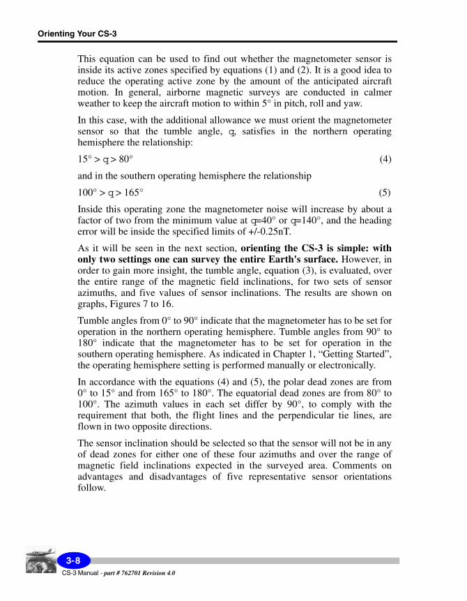
Sensor Inclination 90°
From the graph in Figure 8, you can determine the value of the tumble angle (the angle between the magnetic field and the sensor optical axis) for all possible values of the magnetic field inclination. Because the sensor is vertical, the tumble angle is independent of the sensor azimuth (one curve is valid for all azimuths).
The operating range of the magnetic field inclinations, for which the tumble angle is inside the active operating zone, is indicated by horizontal arrows in the graph. The sensor orientation shown in the Figure 7 is very useful because it covers most of the Earth's surface with the exception of polar and equatorial regions.
Figure 7 - Plot of tumble angle versus magnetic fieldinclination. Sensor inclination is 90°. Any sensor azimuth
can be used.
3-9CS-3 Manual - part #762701 Revision 4.0

Orienting Your CS-3
Sensor Inclination 67.5°
Sensor azimuth values used in Figure 8 are 0, 90, 180 and 270 degrees. Please note, that the sensor azimuth may differ from the flight direction azimuth, as the sensor axis may have to be set out of the airplane axis. For example, if the line (flight) direction is NE, and the sensor azimuth is to be 90°, then the sensor axis is to be rotated by 45° clockwise from the airplane axis. The particular sensor orientation shown in Figure 8 does not offer any advantages.
Figure 8 - Plot of tumble angle versus magnetic fieldinclination. Sensor inclination is 67.5°. Sensor azimuths are
0, 90, 180 and 270 degrees.
A more advantageous orientation is one with the same sensor inclination, but different azimuths, Figure 9. Large areas extending from either pole down to the field inclination of 25° could be surveyed using this orientation. However, the operation is at the edge of the active zone for the magnetic field inclinations around +/-75°.
CS-3 Manual - part # 762701 Revision 4.0
3-10

Orien
tation
Figure 9 - Plot of tumble angle versus magnetic fieldinclination. Sensor inclination is 67.5°. Sensor azimuths are
45, 135, 225 and 315 degrees.
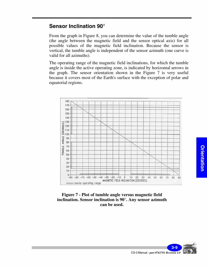
Sensor Inclination 47.5°
Tumble angles for the sensor azimuths parallel or perpendicular to the magnetic field direction could be determined from the graph in Figure 10.
This orientation could be used in surveying polar regions. If the azimuth of 90° and 270° are used for flying normal survey lines, the tumble angle is same for both up-the-line and down-the-line flying, and it is well inside the active zone. The sensor orientation shown in Figure 11 offers the advantage of use for surveys in ether polar or equatorial regions.
3-11CS-3 Manual - part # 762701 Revision 4.0
Orienting Your CS-3
Figure 10 - Plot of tumble angle versus magnetic fieldinclination. Sensor inclination is 47.5°. Sensor azimuths are
0, 90, 180 and 270 degrees.
Please note, that, when flying in equatorial regions, the sensor operating hemisphere has to be changed from north to south when the flight direction, on either normal or tie survey lines, is changed. The same applies for any other orientation used for surveying in equatorial magnetic field regions.
CS-3 Manual - part # 762701 Revision 4.0
3-12
Orien
tation
Figure 11 - Plot of tumble angle versus magnetic fieldinclination. Sensor inclination is 47.5°. Sensor azimuths are
45, 135, 225 and 315 degrees.
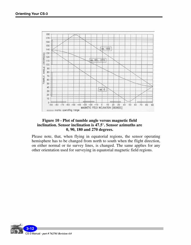
For completeness, the orientation with azimuths between those shown in Figures 10 and 11 is shown in Figure 12. As it can be seen, it does not offer any additional advantages.
3-13CS-3 Manual - part # 762701 Revision 4.0

Orienting Your CS-3
Figure 12 - Plot of tumble angle versus magnetic fieldinclination. Sensor inclination is 47.5°. Sensor azimuths are
23, 113, 203 and 293 degrees.
CS-3 Manual - part # 762701 Revision 4.0
3-14
Orien
tation
Sensor Inclination 22.5°
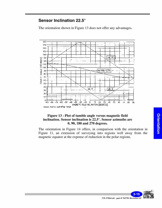
The orientation shown in Figure 13 does not offer any advantages.
Figure 13 - Plot of tumble angle versus magnetic fieldinclination. Sensor inclination is 22.5°. Sensor azimuths are
0, 90, 180 and 270 degrees.
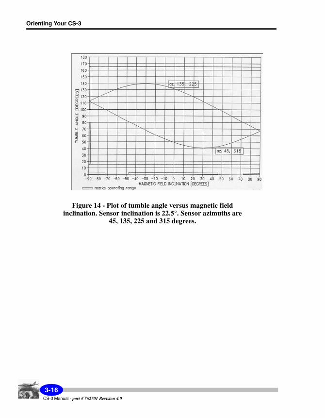
The orientation in Figure 14 offers, in comparison with the orientation in Figure 11, an extension of surveying into regions well away from the magnetic equator at the expense of reduction in the polar regions.
3-15CS-3 Manual - part # 762701 Revision 4.0
Orienting Your CS-3
Figure 14 - Plot of tumble angle versus magnetic fieldinclination. Sensor inclination is 22.5°. Sensor azimuths are
45, 135, 225 and 315 degrees.
CS-3 Manual - part # 762701 Revision 4.0
3-16

Orien
tation
Sensor Inclination 0°
The orientation in Figure 15 is not acceptable, as the tie lines are in dead zones.
Figure 15 - Plot of tumble angle versus magnetic fieldinclination. Sensor inclination is 0°. Sensor azimuths are
0, 90, 180 and 270 degrees.
The orientation shown in Figure 16 has the advantage of covering the entire Earth except the polar regions. For large area, up to the field inclination of +/-45°, the sensor operates far from the dead zones, but the sensor operating hemisphere has to be changed when the flight direction is reversed.
3-17CS-3 Manual - part # 762701 Revision 4.0
Orienting Your CS-3
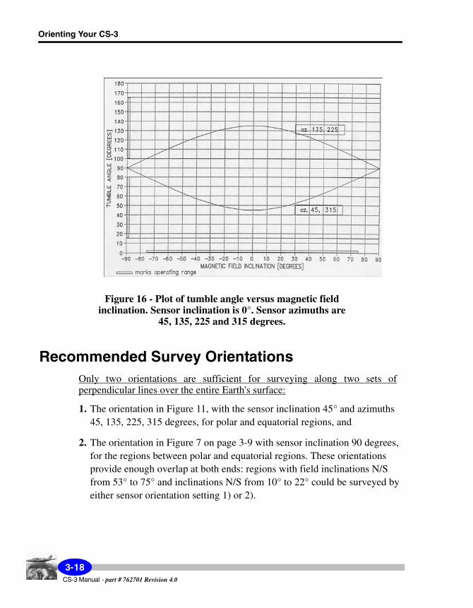
Figure 16 - Plot of tumble angle versus magnetic fieldinclination. Sensor inclination is 0°. Sensor azimuths are
45, 135, 225 and 315 degrees.
Recommended Survey OrientationsOnly two orientations are sufficient for surveying along two sets of perpendicular lines over the entire Earth's surface:
1. The orientation in Figure 11, with the sensor inclination 45° and azimuths 45, 135, 225, 315 degrees, for polar and equatorial regions, and
2. The orientation in Figure 7 on page 3-9 with sensor inclination 90 degrees, for the regions between polar and equatorial regions. These orientations provide enough overlap at both ends: regions with field inclinations N/S from 53° to 75° and inclinations N/S from 10° to 22° could be surveyed by either sensor orientation setting 1) or 2).
CS-3 Manual - part # 762701 Revision 4.0
3-18

Orien
tation
In the overlap regions the tumble angle comes close to boundary of the dead zones. For a larger safety margin following alternate orientation is strongly recommended:
3. The operation around the magnetic equator, extending well into the regions with the magnetic field inclinations up to 45°, could be covered with the sensor inclination 0° and azimuths 45, 135, 225, 315 degrees (see Figure 17).
If the above three orientations are used in both Earth's magnetic hemispheres as follows:
• the orientation a) for the field inclinations from 60° to 90°
• the orientation b) for the field inclinations from 35° to 60°
• the orientation c) for the field inclinations from 0° to 35°
then:
1. the minimum safety margin to the boundary of the operating range is 14° and it will occur for the field inclination 62°
2. the safety margin less than 15° will occur only for the range of the field inclinations from 60° to 65°
3. the safety margin less than 20° will occur for the range of the field inclina-tions from 55° to 78°.
Note:
The additional allowance of 5° has been already subtracted from the essential operating range specified by relationships (1) and (2) to arrive to the reduced operating range, relationships (4) and (5) for which the above analysis applies.
3-19CS-3 Manual - part # 762701 Revision 4.0

Orienting Your CS-3
Comparison with the Locked OscillatorOptically pumped magnetometers using the locked oscillator principle of operation exhibit two distinct features as far as the operating range is concerned:
• there is no polar dead zone, only the equatorial dead zone is present
• the magnetometer operates in both magnetic hemispheres of the ambient field without any adjustment.
Modern self-oscillating magnetometers, like the CS-3 have overcome the shortcoming of two operating hemispheres by incorporating an effective electronic control of the operating hemisphere selection.
The asset of having only one dead zone was claimed to be a valuable operational advantage "without orientation problems associated with self-oscillating alkali vapor magnetometers" (e.g. EG&G brochure for the G-833 Helium Magnetometer). The following rigorous analysis will prove that the CS-3 has superior orienting capabilities.
The operating range of the locked oscillator extends 65° from the polar orientations according to the relationships:
0° < q< 65° (4)
and from
115° < q< 180° (5)
It has been experimentally determined by impartial evaluators that inside this operating zone the magnetometer noise will increase by about a factor of three from the minimum value at q=0° or q=180°. Passed this range, noise increases rapidly, e.g. at 70° from the polar orientation the noise is 7-8 times larger than in the polar orientation.
The graphs shown in Figures 7 to 16 apply for the locked oscillator as well while taking into the account the operating range specified by relationship (4) and (5).
CS-3 Manual - part # 762701 Revision 4.0
3-20

Orien
tation
Only two orientations are useful and they are sufficient for surveying along two sets of perpendicular lines over the entire Earth's surface:
1. the orientation in Figure 7, with sensor inclination 90 degrees, for the ambient field inclinations from 25° to 90°.
2. the operation around the magnetic equator, extending well into the regions with the magnetic field inclinations up to 55°, is covered with the sensor inclination 0° and azimuths 45, 135, 225, 315 degrees, Figure 16.
If the above orientations are used in both Earth's magnetic hemispheres as follows:
• the orientation 1) for the field inclinations from 35° to 90°
• the orientation 2) for the field inclinations from 0° to 35°
then:
i) the minimum safety margin to the boundary of the operating range is 10° and it will occur for the field inclination 35°
ii) the safety margin less than 15° will occur only for the range of the field inclinations from 25° to 40°
iii) the safety margin less than 20° will occur for the range of the field inclinations from 0° to 45°.
• By comparing the criteria i) to iii) above with the same criteria for the CS-3, one can see that the CS-3 offers superior worldwide orienting capabilities.
3-21CS-3 Manual - part # 762701 Revision 4.0

Orienting Your CS-3
CS-3 Manual - part # 762701 Revision 4.0
3-22
Main
tenan
ce
4 Maintaining Your CS-3 and Trouble-shooting
No maintenance is required. Both, the sensor head and the sensor electronics are enclosed in sealed, splashproof housings.
Important:
Care must be exercised in handling the CS-3, especially the sensor head, which contains delicate optical components. Excessive shocks and vibrations should be avoided.
Warning:
BEFORE THE POWER IS APPLIED TO THE CS-3, THE CONNECTOR AT THE END OF THE SENSOR HEAD CABLE HAS TO BE CONNECTED TO THE MATING SOCKET LOCATED AT THE ELECTRONICS BOX SIDE PLATE. THIS CONNECTOR SHOULD NEVER BE DISCONNECTED WHILE THE POWER IS APPLIED TO THE CS-3. DOING SO WILL RESULT IN SERIOUS DAMAGE TO THE RF EXCITER AND WILL VOID THE WARRANTY.
4-1CS-3 Manual - part # 762701 Revision 4.0

Maintaining Your CS-3 and Trouble-shooting
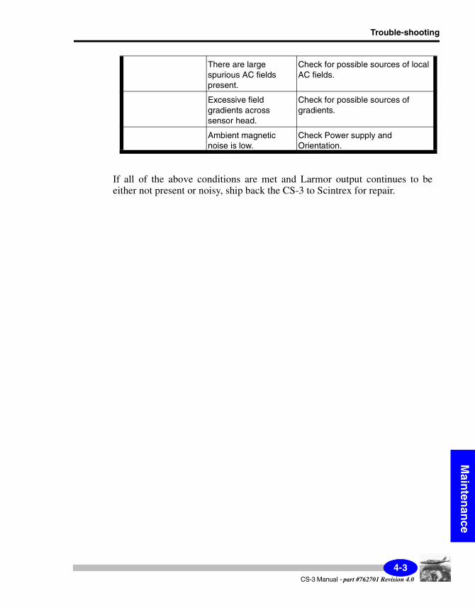
Trouble-shootingDespite the fact that your CS-3 is a very reliable instrument, there can be two circumstances where problems may occur. The following table lists some of these problems and their attempted solution. However, please do not hesitate to contact your nearest Scintrex office. See “Warranty and Repair” on page 5-3 for the office nearest you.
Problem Possible cause Possible solution
No Larmor signal output
The indication that the CS-3 is receiving power is glowing of the green light. If the light is not glowing, and the power is supplied, then the fuse may be blown.
Check that power is supplied by measuring the voltage at either the I/O connector (pin B positive, pin A negative) or the power TNC coaxial connector (center positive), and then replace the fuse by undoing the fuse cover.
The fuse used is Littlefuse type Micro 273 003, 125V AC/DC, 3A.
The power is not supplied to the sensor electronics.
Check power supply.
Power supply as measured at points indicated above is not in the range of 24V to 35V DC.
Check power supply. Note, a lower supply voltage is insufficient for proper operation, while a higher supply voltage will result in excessive dissipation of the internal voltage regulators, and may cause permanent damage.
Current supply not in range.
The supply current after 15 minutes warm-up is in the range 0.5 A (ambient temperature close to 50°C) to 0.8A (ambient temperature close to -40°C).
Sensor head oriented in the active zone.
Refer to the Orienting the CS-3 chapter.
Larmor output (readings) are
noisy.
Possible conditions as noted for no Larmor signal output.
Refer to above solutions.
CS-3 Manual - part # 762701 Revision 4.0
4-2
Trouble-shooting
Main
tenan
ce
If all of the above conditions are met and Larmor output continues to be either not present or noisy, ship back the CS-3 to Scintrex for repair.
There are large spurious AC fields present.
Check for possible sources of local AC fields.
Excessive field gradients across sensor head.
Check for possible sources of gradients.
Ambient magnetic noise is low.
Check Power supply and Orientation.
4-3CS-3 Manual - part #762701 Revision 4.0

Maintaining Your CS-3 and Trouble-shooting
4-4CS-3 Manual - part # 762701 Revision 4.0
Referen
ce
5 Reference Information
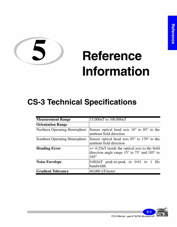
CS-3 Technical Specifications
Measurement Range 15,000nT to 100,000nTOrientation RangeNorthern Operating Hemisphere Sensor optical head axis 10° to 85° to the
ambient field directionSouthern Operating Hemisphere Sensor optical head axis 95° to 170° to the
ambient field directionHeading Error +/- 0.25nT inside the optical axis to the field
direction angle range 15° to 75° and 105° to 165°
Noise Envelope 0.002nT peak-to-peak in 0.01 to 1 Hz bandwidth
Gradient Tolerance 40,000 nT/meter
5-1CS-3 Manual - part # 762701 Revision 4.0
Reference Information
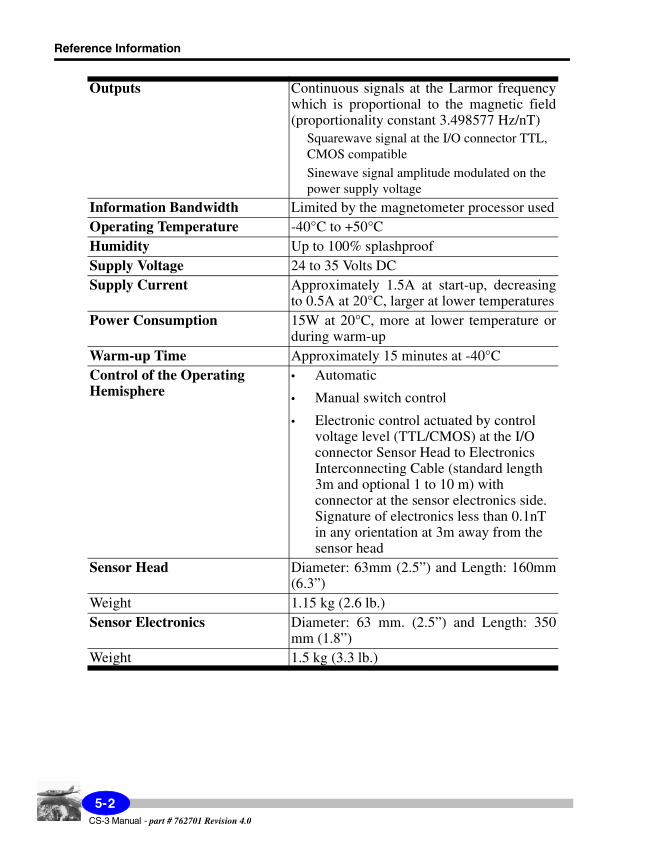
Outputs Continuous signals at the Larmor frequency which is proportional to the magnetic field (proportionality constant 3.498577 Hz/nT)
Squarewave signal at the I/O connector TTL, CMOS compatible
Sinewave signal amplitude modulated on the power supply voltage
Information Bandwidth Limited by the magnetometer processor usedOperating Temperature -40°C to +50°CHumidity Up to 100% splashproofSupply Voltage 24 to 35 Volts DCSupply Current Approximately 1.5A at start-up, decreasing
to 0.5A at 20°C, larger at lower temperaturesPower Consumption 15W at 20°C, more at lower temperature or
during warm-upWarm-up Time Approximately 15 minutes at -40°CControl of the Operating Hemisphere
• Automatic
• Manual switch control
• Electronic control actuated by control voltage level (TTL/CMOS) at the I/O connector Sensor Head to Electronics Interconnecting Cable (standard length 3m and optional 1 to 10 m) with connector at the sensor electronics side. Signature of electronics less than 0.1nT in any orientation at 3m away from the sensor head
Sensor Head Diameter: 63mm (2.5”) and Length: 160mm (6.3”)
Weight 1.15 kg (2.6 lb.)Sensor Electronics Diameter: 63 mm. (2.5”) and Length: 350
mm (1.8”)Weight 1.5 kg (3.3 lb.)
CS-3 Manual - part # 762701 Revision 4.0
5-2

Instrument Parts List
Referen
ce
Instrument Parts List
CS-3 Standard Accessories
Warranty and Repair
WarrantyAll Scintrex equipment, with the exception of consumable items, is warranted against defects in materials and workmanship for a period of one year from the date of shipment from our plant. Should any defects become evident under normal use during the warranty period, Scintrex will make the necessary repairs free of charge.
This warranty does not cover damage due to misuse or accident and may be voided if the instrument console is opened or tampered with by persons not authorized by Scintrex.
Item DescriptionSCINTREXPart Number
CS-3 Magnetometer (includes:) 762-010
Case
Sensor
Electronic processing unit
5-3CS-3 Manual - part #762701 Revision 4.0
Reference Information
RepairWhen To Ship the Unit
Please do not ship your instrument for repair until have communicated the nature of the problem to our Customer Service Department by e-mail, telephone, facsimile or correspondence. Our Customer Service Department may suggest certain simple tests or steps for you to do which may solve your problem without the time and expense involved in shipping the instrument back to Scintrex for repair. If the problem cannot be resolved, our personnel will request that you send the instrument to our plant for the necessary repairs.
Description of the Problem
When you describe the problem, please include the following information:
• the symptoms of the problem,• how the problem started,• if the problem is constant, intermittent or repeatable,• if constant, under what conditions does it occur,• any printouts demonstrating the problem
Shipping InstructionsNo instrument will be accepted for repair unless it is shipped prepaid. After repair, it will be returned collect, unless other arrangements have been made with Scintrex. Please mention the instrument’s serial number in all communications regarding equipment leased or purchased from Scintrex.
Head Office
Instruments within Canada should be shipped to:
SCINTREX Limited
222 Snidercroft Road
CS-3 Manual - part # 762701 Revision 4.0
5-4

Warranty and Repair
Referen
ce
Unit #1
Concord, Ontario
L4K 2K1
tel: +1 905 669 2280
fax: +1 905 669 9899
e-mail: [email protected]
5-5CS-3 Manual - part #762701 Revision 4.0

Reference Information
CS-3 Manual - part # 762701 Revision 4.0
5-6

Th
eory
A Theory of Operation
System OverviewAs shown below, the CS-3 sensor consists of a sensor head with cable and sensor electronics.
Figure A-1 CS-3 Sensor Head and Electronics
The sensor head has an electrodeless discharge lamp (containing cesium vapor) and absorption cell. Electrical heaters bring the lamp and the cell to optimum operating temperatures with control and driving circuits located in the electronics console. Heating currents are supplied to the sensor head through the interconnecting cable.
A-1CS-3 Manual - part #762701 Revision 4.0
When operating, an RF oscillator in the electronics console provides RF power to a lamp exciter in the sensor head and the radio frequency (RF) field produces a corresponding resonant optical radiation (light).
The light radiating from the cesium lamp is collimated by a lens. The light propagates in the direction of the sensor optical axis (as shown in Figure A-1) and passes through an interference filter which selects only the cesium D1 spectral line. The light is subsequently polarized in a split, right/left hand circular polarizer before it is allowed to optically excite cesium vapor in the absorption cell.
The narrow bandwidth resonant light causes momentary alignment (polarization) of the atomic magnetic moments to the direction of the ambient magnetic field. The resonant light "optically pumps" the cesium atoms to a higher energy state. (Note that the polarizing light beam has to be oriented in the general direction of the ambient field to be effective.)
Large numbers of cesium atoms can be polarized by optical pumping and then induced to precess coherently in phase around the ambient field by means of a small magnetic field, H1. This small magnetic field is transverse to the ambient field and alternating at the Larmor frequency.
The H1 field is produced by a coil in the CS-3. The coil is coaxial with the sensor optical axis and wound around the absorption cell. Polarized resonant light perpendicular to the ambient magnetic field detects the precession. This light is alternately more or less absorbed, depending on the instantaneous orientation of the polarization.
In the CS-3, this probing light is the perpendicular component of the resonant light beam. If the modulation of through-the-absorption-cell transmitted light is detected with the photosensitive detector, and the resulting Larmor signal is sufficiently amplified and phase-shifted before being fed back to the H1coil, then a closed loop self-oscillating circuit results.
The resonance occurs at the Larmor frequency, which in weak fields, e.g. the Earth's magnetic field, is precisely linear with the field in which the absorption cell is located. For the cesium 133 the proportionality constant (gyromagnetic constant) is 3.498577 Hz per nT.
As indicated, different components of the same resonant light beam perform two functions:
• the component parallel to the ambient field performs the optical pumping
• the perpendicular component detects the coherent precession.
CS-3 Manual - part # 762701 Revision 4.0
A-2

Th
eory
Therefore, no pumping is taking place if the light beam (the optical axis) is perpendicular to the ambient field (the equatorial orientation) and consequently the sensor is not operating. Equally, no light modulation is taking place if the light beam is parallel with the ambient field (the polar orientation) and consequently the sensor is not operating.
The second reason for the sensor not operating in the polar orientation is that the H1 field, being parallel to the ambient field, can not induce precession of the magnetic polarization.
The plane perpendicular to the ambient field divides the sensor operating zones into two hemispheres - northern and southern operating hemisphere. In the northern operating hemisphere the sensor light beam, which propagates in the direction of the optical axis, Figure A-2, forms an angle from 0° to 90° with the direction of the ambient field. In this hemisphere, the phase shift of the Larmor signal amplifier required for the self-oscillation at the peak of the resonance is -90°.
Figure A-2 Northern Operating Hemisphere
A-3CS-3 Manual - part # 762701 Revision 4.0
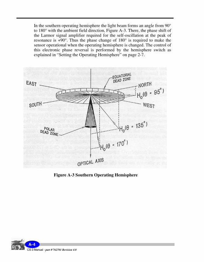
In the southern operating hemisphere the light beam forms an angle from 90° to 180° with the ambient field direction, Figure A-3. There, the phase shift of the Larmor signal amplifier required for the self-oscillation at the peak of resonance is +90°. Thus the phase change of 180° is required to make the sensor operational when the operating hemisphere is changed. The control of this electronic phase reversal is performed by the hemisphere switch as explained in “Setting the Operating Hemisphere” on page 2-7.
Figure A-3 Southern Operating Hemisphere
CS-3 Manual - part # 762701 Revision 4.0
A-4
Th
eory
B CS-3 Block Diagram
As shown on the next page, the CS-3 sensor system includes a variety of sensor and electronic components.
B-1CS-3 Manual - part # 762701 Revision 4.0
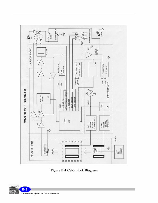
Figure B-1 CS-3 Block Diagram
CS-3 Manual - part # 762701 Revision 4.0
B-2

Ind
ex
2nd
2
2nd Draft
Index
AAbsorption cell
magnetic field measurement 1-6operating temperature 2-5
Active zone of CS-3 3-2
CChapter layout scheme 1-3Cold start-up
power supply current 2-4
GGyromagnetic constant 2-5
HHeading error 3-1, 3-4, 5-1Heaters 1-7Hemisphere control switch
automatic 2-8description 1-8electronic 2-7functions 1-9manual 2-7specifications 5-1use for orientation 3-3
II/O connector
signals 1-9
LLarmour
amplifier 1-7frequency 2-5
output signals 2-5theory A-2
obtaining signal 2-5signal amplitude 3-2
Locked oscillatorcomparison with 3-20
MMagnetic field
measurementabsorption cell 1-6
Magnetometer noise 3-8Manual symbols 1-4
OOperating hemisphere
northern 3-2obtaining proper signal 2-8setting 2-7southern 3-3theory A-3
Optical axis 1-6, 3-2Optically pumped magnetometer
frequency variationcauses 3-1
theory A-2Orientation
in northern hemisphere 3-8in southern hemisphere 3-8
PPage Numbering 1-1Polar dead zones 3-8Powering up
CS-3 Manual - part # 762701 Revision 4.0

four pin I/O connector 2-4TNC connector 2-4
ProcessorsScintrex MEP series 2-6
RRF lamp exciter 1-7
SScintrex
officescontacting 5-4
Selecting sensor inclination 3-8Sensor
electronicscomponents 1-7dimensions 5-2
headactive zone 3-2components 1-5dimensions 5-2housing 1-6
housingpower connections 1-7
Sensor decoupler 2-6Sensor inclination
0° 3-1722.5° 3-1547.5° 3-1167.5° 3-1090° 3-9
Setting upmounting guidelines 2-3procedure 2-2stabilization 2-2voltage 2-2
warning before powering up 2-2Shipping instructions 5-4Spurious magnetic fields
operating in 2-9Survey orientations
recommended 3-18
TTrouble-shooting 4-2 to 4-3
table 4-2Tumble angle
calculating 3-7Type styles scheme 1-2
UUse of gimbals 2-3, 3-4
WWarranty and repair 5-3
CS-3 Manual - part # 762701 Revision 4.0
SCINTREX
Head Office222 Snidercroft RoadUnit #1Concord, OntarioCanada, L4K 2K1tel: +1 905 669 2280fax: +1 905 669 [email protected]
