cs1000 and callpilot server configuration
TRANSCRIPT

Nortel CallPilot
Communication Server 1000 andCallPilot Server Configuration
NN44200-312.

Document status: StandardDocument version: 01.03Document date: 20 December 2007
Copyright © 2007 Nortel NetworksAll Rights Reserved.
Sourced in Canada
The information in this document is subject to change without notice. The statements, configurations, technicaldata, and recommendations in this document are believed to be accurate and reliable, but are presented withoutexpress or implied warranty. Users must take full responsibility for their applications of any products specified in thisdocument. The information in this document is proprietary to Nortel Networks.
The process of transmitting data and call messaging between the CallPilot server and the switch or system isproprietary to Nortel Networks. Any other use of the data and the transmission process is a violation of the userlicense unless specifically authorized in writing by Nortel Networks prior to such use. Violations of the license byalternative usage of any portion of this process or the related hardware constitutes grounds for an immediatetermination of the license and Nortel Networks reserves the right to seek all allowable remedies for such breach.
Trademarks*Nortel Networks, the Nortel Networks logo, the Globemark, and Unified Networks, BNR, CallPilot, DMS, DMS-100,DMS-250, DMS-MTX, DMS-SCP, DPN, Dualmode, Helmsman, IVR, MAP, Meridian, Meridian 1, Meridian Link,Meridian Mail, Norstar, SL-1, SL-100, Succession, Supernode, Contact Center, Telesis, and Unity are trademarks ofNortel Networks.
3COM is a trademark of 3Com Corporation.
ADOBE is a trademark of Adobe Systems Incorporated.
ATLAS is a trademark of Quantum Corporation.
BLACKBERRY is a trademark of Research in Motion Limited.
CRYSTAL REPORTS is a trademark of Seagate Software Inc.
EUDORA and QUALCOMM are trademarks of Qualcomm, Inc.
ETRUST and INOCULATEIT are trademarks of Computer Associates Think Inc.
DIRECTX, EXCHANGE.NET, FRONTPAGE, INTERNET EXPLORER, LINKEXCHANGE, MICROSOFT,MICROSOFT EXCHANGE SERVER, MS-DOS, NETMEETING, OUTLOOK, POWERPOINT, VISUAL STUDIO,WINDOWS, WINDOWS MEDIA, WINDOWS NT, and WINDOWS SERVER are trademarks of Microsoft Corporation.
GROUPWISE and NOVELL are trademarks of Novell Inc.
INTEL is a trademark of Intel Corporation.
LOGITECH is a trademark of Logitech, Inc.
MCAFEE and NETSHIELD are trademarks of McAfee Associates, Inc.
MYLEX is a trademark of Mylex Corporation.
NETSCAPE COMMUNICATOR is a trademark of Netscape Communications Corporation.
NOTES is a trademark of Lotus Development Corporation.
NORTON ANTIVIRUS and PCANYWHERE are trademarks of Symantec Corporation.
QUICKTIME is a trademark of Apple Computer, Inc.
RADISYS is a trademark of Radisys Corporation.
ROLM is a trademark of Siemens ROLM Communications Inc.
SLR4, SLR5, and TANDBERG are trademarks of Tandberg Data ASA.
SONY is a trademark of Sony Corporation.
SYBASE is a trademark of Sybase, Inc.
TEAC is a trademark of TEAC Corporation.
US ROBOTICS, the US ROBOTICS logo, and SPORTSTER are trademarks of US Robotics.
WINZIP is a trademark of Nico Mark Computing, Inc.
XEON is a trademark of Intel, Inc.
All other trademarks and registered trademarks are the property of their respective owners.

5
Publication History
Dec 2007CallPilot 5.0, Standard 01.03 of Communication Server 1000 and CallPilotServer Configuration issued for review. Added information pertaining tothe new MGate card (NTRB18DA)
May 2007CallPilot 5.0, Standard 01.02 of Communication Server 1000 and CallPilotServer Configuration issued for general availability. Added informationpertaining to CS 1000 Release 5.0
March 2007CallPilot 5.0, Standard 01.01 of Communication Server 1000 and CallPilotServer Configuration issued for general availability.
Nortel CallPilotCommunication Server 1000 and CallPilot Server Configuration
NN44200-312 01.03 Standard5.0 20 December 2007
Copyright © 2007, Nortel Networks
.

6 Publication History
Nortel CallPilotCommunication Server 1000 and CallPilot Server Configuration
NN44200-312 01.03 Standard5.0 20 December 2007
Copyright © 2007, Nortel Networks
.
7
Contents
Chapter 1 How to get help 9
Chapter 2 CallPilot and CS 1000 connectivity overview 11Overview 11
Reference Documents 12Contact Center Voice Services Support 16Section A: CallPilot network setup 17CallPilot and CS 1000 integration 18CS 1000 Media Gateway 21Section B: Understanding call routing 22CS 1000 call routing components 23Phantom DNs 24CallPilot Service Directory Numbers and the SDN Table 25How calls are routed 27Multimedia channels in the CallPilot server 29How multimedia channels are acquired by callers 29
Chapter 3 Connecting the CallPilot server to the CS 1000system 31
Section A: Installing the MGate card 31About the MGate card (NTRB18CA or NTRB18DA) 32Installing the MGate card (NTRB18CA or NTRB18DA) 34Replacing an MGate card (NTRB18CA or NTRB18DA) 38Section B: Connecting the CallPilot server to the switch 40About the DS30X cable 40Connecting MPB16-4 boards to MGate cards (NTRB18CA or NTRB18DA) 42Connecting the MPB96 boards to MGate cards (NTRB18CA or NTRB18DA) 47
Chapter 4 Configuring the CS 1000 system 51CS 1000 hardware and software requirements 52CS 1000 configuration checklist 52Provisioning the ELAN subnet 56Defining the Message Register for AML message tracing 58Configuring CS 1000 IP addresses and enabling the Ethernet interface 59Defining CallPilot in the customer data block 62Configuring the ACD agent queue 67
Nortel CallPilotCommunication Server 1000 and CallPilot Server Configuration
NN44200-312 01.03 Standard5.0 20 December 2007
Copyright © 2007, Nortel Networks
.
8 Contents
Configuring ACD agents 68Enabling the card slots 70Defining the default ACD DN 71Configuring CDN queues for messaging services 72Configuring phantom DNs 73Configuring dummy ACD DNs 76Provisioning user phonesets 77Configuring the route data block for Network Message Service 80Saving CS 1000 changes 81
Chapter 5 Configuring the CallPilot server software 83Overview 83Logging on to Windows 2003 on the CallPilot server 84Running the Setup Wizard 85Logging on to the CallPilot server with CallPilot Manager 86Running the Configuration Wizard 91Changing pcAnywhere caller passwords 94Setting Remote Desktop Policy on a Server 95Configuring CallPilot to operate in a Windows 2000 or 2003 domain 97
Chapter 6 Testing the CallPilot installation 109Checking that CallPilot is ready to accept calls 109Testing the connection to the ELAN subnet 113Testing the connection to the NNS Subnet 114Verifying that CallPilot can receive calls 114Testing the CallPilot software and channels 115
Nortel CallPilotCommunication Server 1000 and CallPilot Server Configuration
NN44200-312 01.03 Standard5.0 20 December 2007
Copyright © 2007, Nortel Networks
.
9
Chapter 1How to get help
This section explains how to get help for Nortel products and services.
Getting help from the Nortel Web siteThe best way to get technical support for Nortel products is from the NortelTechnical Support Web site:
http://www.nortel.com/support
This site provides quick access to software, documentation, bulletins, andtools to address issues with Nortel products. More specifically, the siteenables you to:
• download software, documentation, and product bulletins
• search the Technical Support Web site and the Nortel Knowledge Basefor answers to technical issues
• sign up for automatic notification of new software and documentationfor Nortel equipment
• open and manage technical support cases
Getting help over the phone from a Nortel Solutions CenterIf you don’t find the information you require on the Nortel Technical SupportWeb site, and have a Nortel support contract, you can also get help over thephone from a Nortel Solutions Center.
In North America, call 1-800-4NORTEL (1-800-466-7835).
Outside North America, go to the following Web site to obtain the phonenumber for your region:
http://www.nortel.com/callus
Nortel CallPilotCommunication Server 1000 and CallPilot Server Configuration
NN44200-312 01.03 Standard5.0 20 December 2007
Copyright © 2007, Nortel Networks
.

10 Chapter 1 How to get help
Getting help from a specialist by using an Express Routing CodeTo access some Nortel Technical Solutions Centers, you can use an ExpressRouting Code (ERC) to quickly route your call to a specialist in your Nortelproduct or service. To locate the ERC for your product or service, go to:
http://www.nortel.com/erc
Getting help through a Nortel distributor or resellerIf you purchased a service contract for your Nortel product from a distributoror authorized reseller, contact the technical support staff for that distributoror reseller.
Nortel CallPilotCommunication Server 1000 and CallPilot Server Configuration
NN44200-312 01.03 Standard5.0 20 December 2007
Copyright © 2007, Nortel Networks
.

11
Chapter 2CallPilot and CS 1000 connectivityoverview
In this chapter"Overview" (page 11)
"Contact Center Voice Services Support" (page 16)
"Section A: CallPilot network setup" (page 17)
"CallPilot and CS 1000 integration" (page 18)
"CS 1000 Media Gateway" (page 21)
"Section B: Understanding call routing" (page 22)
"CS 1000 call routing components" (page 23)
"Phantom DNs" (page 24)
"CallPilot Service Directory Numbers and the SDN Table" (page 25)
"How calls are routed" (page 27)
"Multimedia channels in the CallPilot server" (page 29)
"How multimedia channels are acquired by callers" (page 29)
OverviewIntroduction
This guide describes the Communication Server 1000 (CS* 1000) systemsetup and CallPilot* server configuration steps of the CallPilot installation.This guide includes:
• configuring the CS 1000 system for correct operation with CallPilot
Nortel CallPilotCommunication Server 1000 and CallPilot Server Configuration
NN44200-312 01.03 Standard5.0 20 December 2007
Copyright © 2007, Nortel Networks
.
12 Chapter 2 CallPilot and CS 1000 connectivity overview
• connecting the CallPilot system to the CS 1000 system and the NortelServer Subnet (NS Subnet)
• configuring the CallPilot server
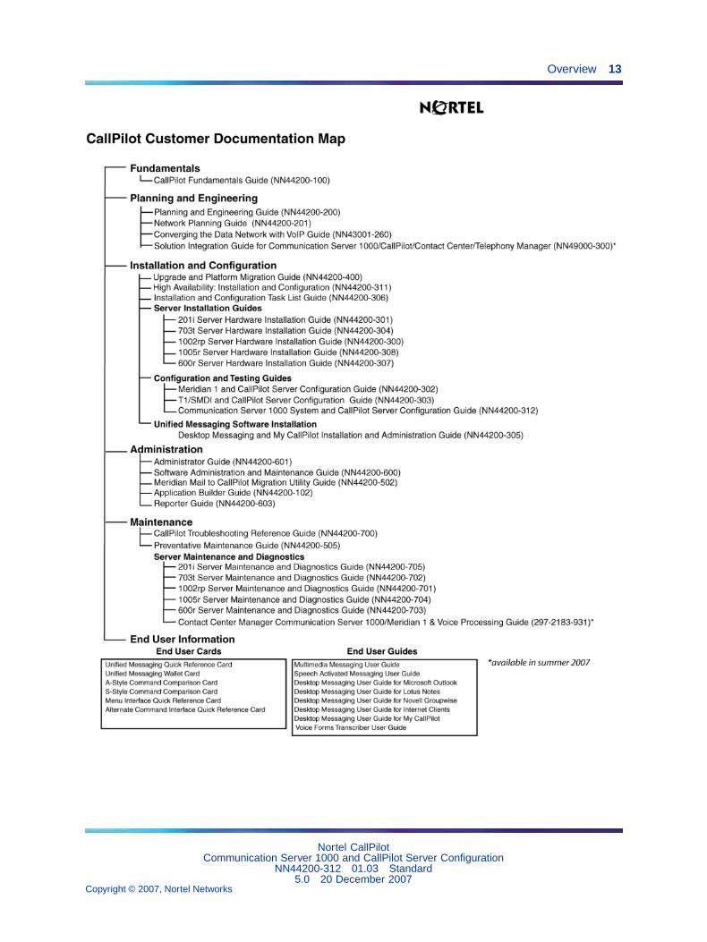
Reference DocumentsFor a list of all CallPilot documents, see the following CustomerDocumentation Map.
Nortel CallPilotCommunication Server 1000 and CallPilot Server Configuration
NN44200-312 01.03 Standard5.0 20 December 2007
Copyright © 2007, Nortel Networks
.
Overview 13
Nortel CallPilotCommunication Server 1000 and CallPilot Server Configuration
NN44200-312 01.03 Standard5.0 20 December 2007
Copyright © 2007, Nortel Networks
.
14 Chapter 2 CallPilot and CS 1000 connectivity overview
Before you beginBefore configuring the CS 1000 system and CallPilot server:
• Review the Installing CallPilot section in the CallPilot Installation andConfiguration Task List.
• Complete stage 2 of the CallPilot Installation and Configuration Task List.
• Complete the worksheets in the CallPilot Installation and ConfigurationTask List.
Note: If you need a high-level overview of CallPilot and CS 1000connectivity, then read the remainder of this chapter.
Otherwise, the installation steps begin in the following chapters:
• for tower or rackmount servers, in Chapter 3 "Connecting the CallPilotserver to the CS 1000 system" (page 31)
• for the 201i server, in Chapter 4 "Configuring the CS 1000 system"(page 51)
Complete the steps in each chapter before you continue to the next chapter.
Installation and configuration checklistCheck off the stages and steps in "Installation and configuration checklist"(page 14) as they are completed.
Installation and configuration checklist
Step Description Check
Stage 1: Install the connectivity hardware.
Note: For the 201i server, this stage is not applicable.Hardware connectivity is established when the 201i server isinstalled in the CS 1000 system, as described in the CallPilot201i Server Hardware Installation Guide.
1 If your server is a tower or rackmount server, install theMGate card (NTRB18CA or NTRB18DA) in the CS 1000system. For instructions, see "Installing the MGate card(NTRB18CA or NTRB18DA)" (page 34).
2 Connect the tower or rackmount server to the CS 1000system. For instructions, see "Section B: Connecting theCallPilot server to the switch" (page 40).
Nortel CallPilotCommunication Server 1000 and CallPilot Server Configuration
NN44200-312 01.03 Standard5.0 20 December 2007
Copyright © 2007, Nortel Networks
.

Overview 15
Step Description Check
Stage 2: Configure the CS 1000 system and CallPilot server.
3 Configure the CS 1000 system. Use the "Switchconfiguration worksheet" that you completed in the CallPilotInstallation and Configuration Task List. For configurationinstructions, see "CS 1000 configuration checklist" (page52).
4 Run the Configuration Wizard and configure the CallPilotserver. Use the "Configuration Wizard worksheet" that youcompleted in the CallPilot Installation and ConfigurationTask List. For configuration instructions, see "Running theConfiguration Wizard" (page 91).
5 Change the pcAnywhere password or set the RemoteDesktop Policy.
• If you are using pcAnywhere, continue to "ChangingpcAnywhere caller passwords" (page 94).
Note: pcAnywhere is not supported on the CallPilot 201isystem. Continue to "Setting Remote Desktop Policy on aServer" (page 95).
• If you are using Remote Desktop Connection, continueto "Setting Remote Desktop Policy on a Server" (page95).
Stage 3: Test CallPilot connectivity.
Note: For instructions, see Chapter 6 "Testing the CallPilotinstallation" (page 109).
6 Check the CallPilot system-ready indicators to see ifCallPilot is ready to accept calls.
7 Test the connection to the ELAN subnet, if applicable.
8 Test the connection to the Nortel Server Subnet (NSSubnet).
9 Verify that CallPilot answers when you dial the VoiceMessaging DN.
Stage 4: Test the CallPilot services and channels.
Note: For instructions, see Chapter 6 "Testing the CallPilotinstallation" (page 109).
10 Check the system-ready indicators.
Nortel CallPilotCommunication Server 1000 and CallPilot Server Configuration
NN44200-312 01.03 Standard5.0 20 December 2007
Copyright © 2007, Nortel Networks
.
16 Chapter 2 CallPilot and CS 1000 connectivity overview
Step Description Check
11 Verify network connectivity to the CallPilot server over theELAN subnet and NNS Subnet.
12 Verify that CallPilot can receive calls.
13 Verify that you can leave a message.
14 Verify that you can retrieve a message.
15 Verify that each call channel and multimedia channel isfunctioning correctly.
16 Check for CallPilot alarms using the Alarm Monitor inCallPilot Manager. Upon confirmation that CallPilot isoperating correctly, clear all alarms.
Stage 5: Install CallPilot Manager on a stand-alone web server (optional).
17 Perform this step only if you want to set up a separateweb server for CallPilot administration. This is necessaryif you want to use the Reporter application, or if highadministration traffic is expected. For instructions, see theCallPilot Software Administration Guide.
Contact Center Voice Services SupportIntroduction
This section is applicable only if you are enabling the Contact Center* VoiceServices Support feature. This section provides an overview of the specificCS 1000 configuration steps required for the Contact Center Voice ServicesSupport feature.
Notes:
For Contact Center integration with CallPilot, Contact Center channels canonly be voice channels.
ACD overflow is not supported.
Configuring the CS 1000 system to support CallPilot and Contact CenterServer
This guide provides the specific CS 1000 system configuration instructionsrequired to support CallPilot. Where there is an exception or additionalstep required for the Contact Center Voice Services Support feature, thisinformation is also provided. A list of these exceptions and additional stepsis provided below:
1. In overlay 17 (see "Provisioning the ELAN subnet" (page 56)), the SECUprompt must be set to YES.
Nortel CallPilotCommunication Server 1000 and CallPilot Server Configuration
NN44200-312 01.03 Standard5.0 20 December 2007
Copyright © 2007, Nortel Networks
.
Section A: CallPilot network setup 17
2. You must set up two additional ACD agent queues: one for ACCESSports, and one for IVR* ports. See "Configuring the ACD agent queue"(page 67).
3. In overlay 11, you must specify AST 0 1, where 0 is the number for key0, and 1 is the number for key 1.
Configuring CallPilot for Contact Center Voice Services SupportTo configure CallPilot for Contact Center Voice Services Support, makethe following changes.
1. In the Configuration Wizard, you must specify the following informationfor the Contact Center Voice Services Support feature:
• On the CS 1000 Information web page, you must specify the ContactCenter Server NNS Subnet IP address.
• In the Channel Detail Information dialog box, you must select thecheck box for ACCESS or IVR for channels that are to be used forthe Contact Center Voice Services Support feature. These are thesame channels that you must program on the CS 1000 system inan ACCESS ACD queue or IVR ACD queue. Also specify the ClassID for the channel.
2. In the CallPilot Manager Service Directory Number page, do thefollowing:
• Use the ACCESS ACD-DN to create an SDN for the Contact CenterVoice Services Support feature.
• Define treatment IDs used by Contact Center Server as voice menusor announcements.
See alsoSee the Contact Center Server documentation for additional CS 1000system instructions related to Contact Center Server configuration.
For additional information on Contact Center to CallPilot integration, see theCallPilot Distributor Technical Reference.
Section A: CallPilot network setup
In this section"CallPilot and CS 1000 integration" (page 18)
"CS 1000 Media Gateway" (page 21)
Nortel CallPilotCommunication Server 1000 and CallPilot Server Configuration
NN44200-312 01.03 Standard5.0 20 December 2007
Copyright © 2007, Nortel Networks
.

18 Chapter 2 CallPilot and CS 1000 connectivity overview
CallPilot and CS 1000 integrationIntroduction
This section describes how the CallPilot server is integrated into yournetwork with the CS 1000 system.
Sample network diagrams201i server"201i integrated with CS 1000" (page 18) shows an example of how the 201iserver can be integrated with the CS 1000 system in your network.
201i integrated with CS 1000
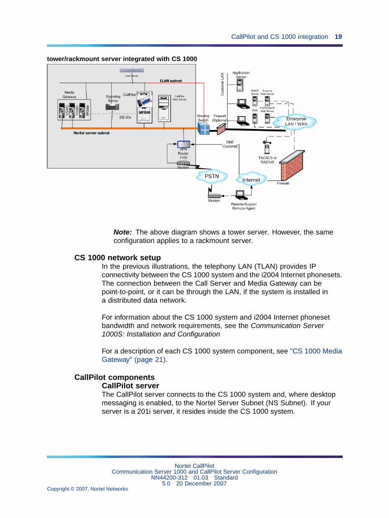
Tower or rackmount servers"tower/rackmount server integrated with CS 1000" (page 19) shows how atower or rackmount server (for example, 703t, or 1002rp) can be integratedwith the CS 1000 system in your network:
Nortel CallPilotCommunication Server 1000 and CallPilot Server Configuration
NN44200-312 01.03 Standard5.0 20 December 2007
Copyright © 2007, Nortel Networks
.
CallPilot and CS 1000 integration 19
tower/rackmount server integrated with CS 1000
Note: The above diagram shows a tower server. However, the sameconfiguration applies to a rackmount server.
CS 1000 network setupIn the previous illustrations, the telephony LAN (TLAN) provides IPconnectivity between the CS 1000 system and the i2004 Internet phonesets.The connection between the Call Server and Media Gateway can bepoint-to-point, or it can be through the LAN, if the system is installed ina distributed data network.
For information about the CS 1000 system and i2004 Internet phonesetbandwidth and network requirements, see the Communication Server1000S: Installation and Configuration
For a description of each CS 1000 system component, see "CS 1000 MediaGateway" (page 21).
CallPilot componentsCallPilot serverThe CallPilot server connects to the CS 1000 system and, where desktopmessaging is enabled, to the Nortel Server Subnet (NS Subnet). If yourserver is a 201i server, it resides inside the CS 1000 system.
Nortel CallPilotCommunication Server 1000 and CallPilot Server Configuration
NN44200-312 01.03 Standard5.0 20 December 2007
Copyright © 2007, Nortel Networks
.
20 Chapter 2 CallPilot and CS 1000 connectivity overview
MGate card (NTRB18CA or NTRB18DA) -- tower and rackmountservers onlyThe MGate card (NTRB18CA or NTRB18DA) is a line card that is installedinside the CS 1000 system. The MGate card sends the voice and datasignals to the MPB boards in the CallPilot server.
MPB boards (for tower and rackmount servers only)The CallPilot server is equipped with one of the following types of MPBboards:
• MPB16-4 boards
DSPs are provided on the MPB16-4 board in the form of two integratedMPCs and up to four optional MPC-8 cards. (For more informationaboutMPC-8 cards, see "MPC-8 cards" (page 20).)
MPB 16-4 boards are no longer shipped with the CallPilot server. TheMPB96 supersedes the MPB16-4.
• MPB96 boards
DSPs are provided on the MPB96 board in the form of 12 integratedMPCs. MPC-8 cards are not required on the MPB96 board.
Each tower or rackmount CallPilot server ships with at least one MPB96board.
MPC-8 cardsThe MPC-8 cards reside in slots in the 201i server, or in the MPB16-4 boardfor tower or rackmount servers. These cards process the voice and datasignals that arrive from the CS 1000 system.
See also "Multimedia channels in the CallPilot server" (page 29).
ModemThe server connects to a modem to allow remote access by a support PCfor installation, maintenance, and diagnostics.
Desktop client PCsYou can install desktop client messaging software on client PCs to enablemailbox users to receive phone, fax, and voicemail on their PCs. For moreinformation, see the Desktop Messaging and My CallPilot Installation Guide(NN44200-305).
Any PC that has network access to the CallPilot server and has a webbrowser installed can be used to administer CallPilot. The CallPilotadministration software is web-based.
Nortel CallPilotCommunication Server 1000 and CallPilot Server Configuration
NN44200-312 01.03 Standard5.0 20 December 2007
Copyright © 2007, Nortel Networks
.
CS 1000 Media Gateway 21
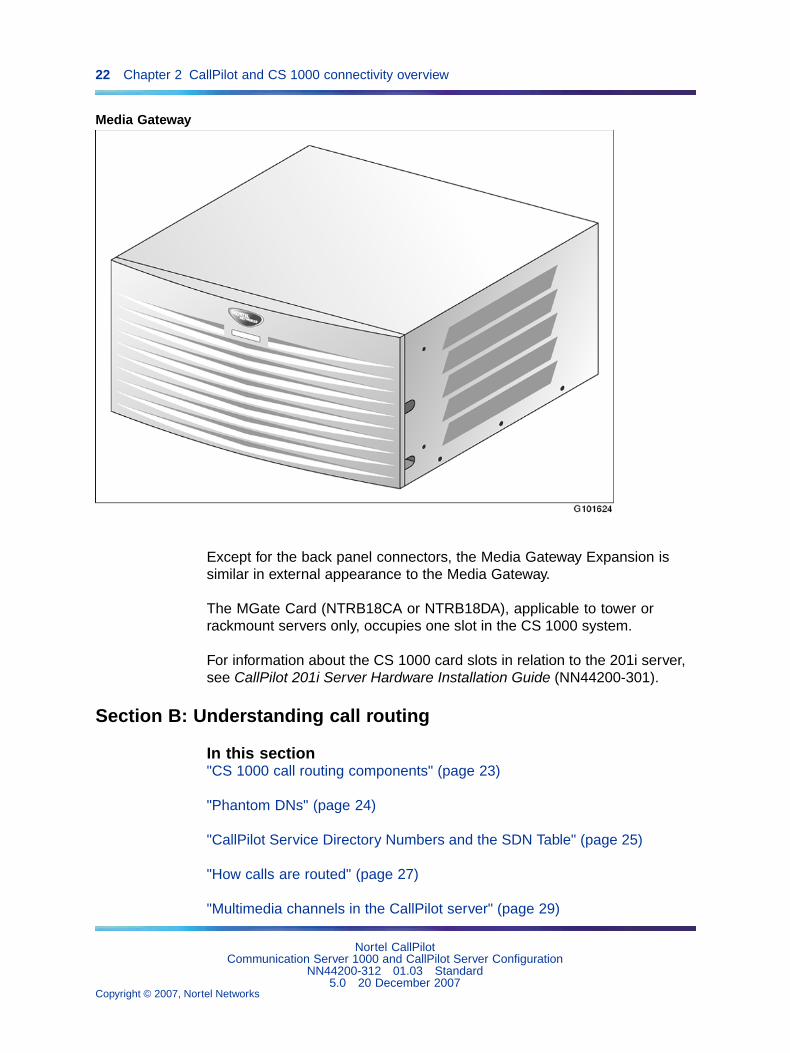
CS 1000 Media GatewayIntroduction
The Media Gateway and Media Gateway Expansion provide the interfacefor analog or digital trunks, i2004 Internet phonesets, analog phonesets,and applications such as CallPilot.
Media Gateway and Media Gateway ExpansionThe Media Gateway and the Media Gateway Expansion provides four IPEslots. These slots support cards such as analog line cards, trunk cards,and application cards. The CallPilot 201i server is an application cardthat occupies two consecutive slots. The MGate Card (NTRB18CA orNTRB18DA) is a line card that occupies only one slot.
For a list of the cards that are supported by the CS 1000 system, see theCommunication Server 1000S: Installation and Configuration
ATTENTIONMedia Gateway shelves in a CS 1000E do not share the same clock reference.Media Gateway expander shelves share the same clock reference as the MediaGateway shelf that they are connected to. In a CS 1000E, all MGate cardsconnected to the CallPilot system must reside in the same Media Gateway/MediaGateway Expansion shelf pair. For the CS 1000M and CS 1000S, the MGatecards can reside in separate shelves.
"Media Gateway" (page 22) shows a Media Gateway.
Nortel CallPilotCommunication Server 1000 and CallPilot Server Configuration
NN44200-312 01.03 Standard5.0 20 December 2007
Copyright © 2007, Nortel Networks
.
22 Chapter 2 CallPilot and CS 1000 connectivity overview
Media Gateway
Except for the back panel connectors, the Media Gateway Expansion issimilar in external appearance to the Media Gateway.
The MGate Card (NTRB18CA or NTRB18DA), applicable to tower orrackmount servers only, occupies one slot in the CS 1000 system.
For information about the CS 1000 card slots in relation to the 201i server,see CallPilot 201i Server Hardware Installation Guide (NN44200-301).
Section B: Understanding call routing
In this section"CS 1000 call routing components" (page 23)
"Phantom DNs" (page 24)
"CallPilot Service Directory Numbers and the SDN Table" (page 25)
"How calls are routed" (page 27)
"Multimedia channels in the CallPilot server" (page 29)
Nortel CallPilotCommunication Server 1000 and CallPilot Server Configuration
NN44200-312 01.03 Standard5.0 20 December 2007
Copyright © 2007, Nortel Networks
.
CS 1000 call routing components 23
"How multimedia channels are acquired by callers" (page 29)
CS 1000 call routing componentsIntroduction
The CS 1000 system uses the following components to route calls:
• Automatic Call Distribution (ACD)
• Control Directory Number (CDN)
Automatic Call DistributionAutomatic Call Distribution (ACD) is a feature on the CS 1000 systemthat allows a number of programmed phonesets, known as ACD agents,to share equally in answering incoming calls. In the case of CallPilot, thecall-queuing capability of ACD is not used, but the call-handling capability ofACD agents is used.
How CallPilot uses ACD virtual agentsAll ACD agents that service CallPilot are put into a single ACD agentqueue (unless you are enabling the Contact Center Voice Services Supportfeature; see "How multimedia channels are acquired by callers" (page29)). These agents correspond to DS0 channels on the CallPilot server.Agents are programmed in overlay 11 as 2008 Digital (Aries) sets withMultimedia Messaging Allowed (MMA) class of service. These are not,however, physical phonesets. These are Terminal numbers (TNs) that areprogrammed to look like real digital sets to the CS 1000 system.
Control Directory NumberFor CallPilot, you configure one Control Directory Number (CDN) on the CS1000 system for each of the following services:
• a primary CDN for Voice Messaging
• a secondary CDN for Multimedia Messaging
A CDN queue is like an ACD queue. The key difference is that calls in theCDN queue are managed by CallPilot, while calls in an ACD queue aremanaged by the CS 1000 system.
Calls are routed to the CDN queue directly or by terminating on a phantomDN or dummy ACD queue, which is forwarded to the CDN.
How CallPilot uses CDNsA CDN can operate in one of two modes:
• control mode
• default mode
Nortel CallPilotCommunication Server 1000 and CallPilot Server Configuration
NN44200-312 01.03 Standard5.0 20 December 2007
Copyright © 2007, Nortel Networks
.
24 Chapter 2 CallPilot and CS 1000 connectivity overview
Normally, a CDN operates in control mode. In control mode, call treatmentand call routing are under the control of the CallPilot server. The CS 1000system simply provides routing to CallPilot. The server specifies the type oftreatment to be given to waiting calls. The server processes the calls on afirst-come, first-served basis and determines to which DS0 channel the callis routed. DS0 channels are configured as agents of an ACD queue.
A CDN can also operate in default mode (for example, when CallPilot isoffline or the AML is down). In default mode, the CS 1000 system takesover call-routing control. Incoming calls receive default treatment providedby the default ACD DN associated with the CDN.
Call queuingIncoming calls to the CDN are queued in the order of arrival. If calls cannotbe processed immediately and must wait in the queue until resources areavailable, the first caller in the queue is handled first.
Call routingThe CallPilot server determines which DS0 channel can provide the dialedservice requested by a waiting call, and instructs the CS 1000 system toroute the call to the associated ACD agent.
See also
• "Phantom DNs" (page 24)
Phantom DNsIntroduction
Instead of using phonesets or dummy ACD DNs to route calls, CallPilot canuse "virtual telephones" that exist only in software and have no associatedhardware. The DN associated with one of these phantom phones is calleda phantom DN.
Creating a Phantom DNTo create a phantom DN, you first create a phantom loop, and then youdefine a TN within that loop. The system recognizes that any TN definedwithin that loop is a phantom TN. Each phantom TN is assigned a DN (thephantom DN). When the DN is entered in the CallPilot Service DirectoryNumber page, it becomes the dialable number of a CallPilot service.
Phantom DNs forward to a CDN queueIncoming calls cannot queue up in the phantom TN as they arrive. When acall arrives at a phantom DN, the system forwards it to a CDN queue beforeit is routed to a multimedia channel for further call handling. However, thesystem remembers the phantom DN to keep track of the requested service.
Nortel CallPilotCommunication Server 1000 and CallPilot Server Configuration
NN44200-312 01.03 Standard5.0 20 December 2007
Copyright © 2007, Nortel Networks
.

CallPilot Service Directory Numbers and the SDN Table 25
Services that should use phantom DNsNortel strongly recommends that you use either phantom DNs or dummyACD DNs (see "Configuring ACD agents" (page 68)) for the followingservices:
• all services created with Application Builder that are directly dialableby callers
• Speech Activated Messaging
• Paced Speech Messaging
• Voice Item Maintenance
• Fax Item Maintenance
• Express Voice Messaging
• Express Fax Messaging
Networking servicesThe following Networking services can either have a unique phantom DNconfigured on the CS 1000 system, or they can share the phantom DN(and SDN) of another service:
• Enterprise Networking
• AMIS Networking
• Integrated AMIS Networking
Share DNs when your supply of available DNs on the CS 1000 system islow. Create a unique DN when you need to closely monitor each service (forexample, so that each service generates its own traffic data in Reporter).
Note: After you configure the SDN in CallPilot, specify with whichservice you are sharing the SDN.
ExampleYou are ready to put a new menu application into service. Phantom DN6120 is available on the CS 1000 system. In the Service Directory Numberpage, you type 6120 as the SDN for this service. This is the number thatcallers dial to access the menu.
CallPilot Service Directory Numbers and the SDN TableIntroduction
When a call arrives at a CDN queue either directly or indirectly from aphantom DN or dummy ACD DN, the CS 1000 system gives the callerringback treatment. While this happens, the dialed DN is looked up in theSDN Table in CallPilot to determine what service is required.
Nortel CallPilotCommunication Server 1000 and CallPilot Server Configuration
NN44200-312 01.03 Standard5.0 20 December 2007
Copyright © 2007, Nortel Networks
.
26 Chapter 2 CallPilot and CS 1000 connectivity overview
What is the SDN Table?The SDN Table is where the CDNs, phantom DNs, or dummy ACD DNs thathave been configured on the CS 1000 system for your CallPilot services arerecorded. In this table, the DN (now called an SDN) is associated with aspecific service. You use the CallPilot Manager Service Directory Numberpage to administer the SDN Table.
What the SDN Table controlsIn addition to specifying which service should be activated when a numberis dialed, the SDN Table also controls
• the type of channel the service acquires (voice, fax, or speechrecognition)
• the number of channels allocated to the service
The SDN configuration determines the minimum number of channelsguaranteed to a service for simultaneous use and the maximum numberof channels that you can use at one time.
• the session behavior for certain services, such as those created withApplication Builder (including the maximum session length and anumber of fax options)
Types of SDNsThere are two types of SDNs--inbound SDNs and outbound SDNs.
Inbound SDNs require DNs on the CS 1000 systemServices that callers dial need inbound SDNs. An inbound SDN correspondsto either a CDN, a phantom DN, or a dummy ACD DN on the CS 1000system, since callers must be able to dial in to the CS 1000 system with aunique number.
Outbound SDNs do not require DNs on the CS 1000 systemCallers do not dial outbound SDNs. The system uses outbound SDNs toplace outbound calls. Because outbound SDNs do not accept incomingcalls, a corresponding CDN, phantom DN, or dummy ACD DN is notnecessary on the CS 1000 system.
The following services use outbound SDNs:
• outcalling services (Remote Notification, Delivery to Telephone, Deliveryto Fax)
• networking services (AMIS Networking and Enterprise Networking)
Nortel CallPilotCommunication Server 1000 and CallPilot Server Configuration
NN44200-312 01.03 Standard5.0 20 December 2007
Copyright © 2007, Nortel Networks
.
How calls are routed 27
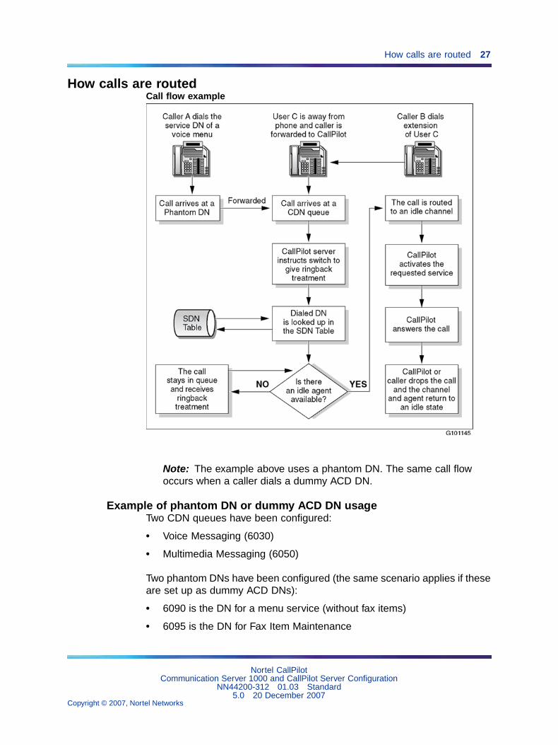
How calls are routedCall flow example
Note: The example above uses a phantom DN. The same call flowoccurs when a caller dials a dummy ACD DN.
Example of phantom DN or dummy ACD DN usageTwo CDN queues have been configured:
• Voice Messaging (6030)
• Multimedia Messaging (6050)
Two phantom DNs have been configured (the same scenario applies if theseare set up as dummy ACD DNs):
• 6090 is the DN for a menu service (without fax items)
• 6095 is the DN for Fax Item Maintenance
Nortel CallPilotCommunication Server 1000 and CallPilot Server Configuration
NN44200-312 01.03 Standard5.0 20 December 2007
Copyright © 2007, Nortel Networks
.
28 Chapter 2 CallPilot and CS 1000 connectivity overview
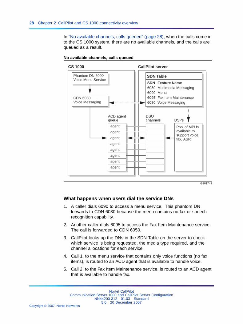
In "No available channels, calls queued" (page 28), when the calls come into the CS 1000 system, there are no available channels, and the calls arequeued as a result.
No available channels, calls queued
G101749
CallPilot serverCS 1000
ACD agentqueue
DSOchannels DSPs
Phantom DN 6090Voice Menu Service
CDN 6030Voice Messaging
SDN Table
SDN Feature Name6050 Multimedia Messaging6090 Menu6095 Fax Item Maintenance6030 Voice Messaging
Pool of MPUs available tosupport voice,fax, ASR
agent
agent
agent
agent
agent
agent
agent
agent
What happens when users dial the service DNs
1. A caller dials 6090 to access a menu service. This phantom DNforwards to CDN 6030 because the menu contains no fax or speechrecognition capability.
2. Another caller dials 6095 to access the Fax Item Maintenance service.The call is forwarded to CDN 6050.
3. CallPilot looks up the DNs in the SDN Table on the server to checkwhich service is being requested, the media type required, and thechannel allocations for each service.
4. Call 1, to the menu service that contains only voice functions (no faxitems), is routed to an ACD agent that is available to handle voice.
5. Call 2, to the Fax Item Maintenance service, is routed to an ACD agentthat is available to handle fax.
Nortel CallPilotCommunication Server 1000 and CallPilot Server Configuration
NN44200-312 01.03 Standard5.0 20 December 2007
Copyright © 2007, Nortel Networks
.
How multimedia channels are acquired by callers 29
Multimedia channels in the CallPilot serverMultimedia Processing Units
In addition to the CPU processing power required by CallPilot, calls that arereceived by CallPilot require DSP processing power to support the voice,fax, and speech recognition features. DSP processing power is providedby Multimedia Processing Units (MPUs) in the CallPilot server. MPUs areprovided by the following CallPilot hardware:
• MPB boards (MPB16-4 for the 1002rp server only, or MPB96)
• MPC-8 cards (if MPB16-4 boards are used)
Types of multimedia channelsCertain types of media require more channel resources to process them.As a result, three types of multimedia channels handle the various types ofCallPilot services. Each type of channel terminates on a different numberof MPUs, based on how much processing power is required. For example,integrated fax and voice data takes twice as much processing power asvoice-only media. A fax channel, therefore, terminates on two MPUs.
Number of MPUs per Channel Type
Channel typeNumber ofMPUs Description
Voice 1 One voice channel requires one MPU.
Fax 2 Fax requires twice as much processingpower as voice-only media, and,therefore, requires two MPUs for one faxchannel.
ASR (automatedspeech recognition)
4 Speech recognition requires four timesas much processing power as voice-onlymedia, and, therefore, requires four MPUsfor one speech recognition channel.
How multimedia channels are acquired by callersIntroduction
The system uses the information gathered from the SDN configuration tocheck the ACD agent queue to determine if an idle multimedia channel ofthe type required by the service is available.
Nortel CallPilotCommunication Server 1000 and CallPilot Server Configuration
NN44200-312 01.03 Standard5.0 20 December 2007
Copyright © 2007, Nortel Networks
.
30 Chapter 2 CallPilot and CS 1000 connectivity overview
IF THEN
an idle channel (of the required mediatype) is available
the system passes the call to CallPilot.
idle channels that meet therequirements defined in the SDNTable are not available
the call remains in the CDN queue andthe system applies a delay treatment.
The server specifies a default delaytreatment of ringback. This means thatwhile a call waits in a queue, the callerhears the phone ringing.
What happens when the call is answeredWhen a multimedia channel of the appropriate type becomes idle, the callarrives at the multimedia channel and is passed to CallPilot.
Because the SDN Table has already been checked, the requested service isknown and is activated. The service also answers the call.
Based on which service is activated, one of the following results happens:
• The appropriate prompt is played.
• CallPilot receives a fax.
• CallPilot records a message.
What happens when the call is droppedWhen CallPilot or the caller drops the call (hangs up), the multimediachannel returns to an idle state, ready to be acquired by another call.
What is next?
IF your server is a THEN
tower or rackmount server (600r, 703t,1002rp, or 1005r)
continue with "Section B: Connectingthe CallPilot server to the switch" (page40).
201i server continue with Chapter 4 "Configuringthe CS 1000 system" (page 51).
Nortel CallPilotCommunication Server 1000 and CallPilot Server Configuration
NN44200-312 01.03 Standard5.0 20 December 2007
Copyright © 2007, Nortel Networks
.

31
Chapter 3Connecting the CallPilot server to theCS 1000 system
In this chapter"Section A: Installing the MGate card" (page 31)
"About the MGate card (NTRB18CA or NTRB18DA)" (page 32)
"Installing the MGate card (NTRB18CA or NTRB18DA)" (page 34)
"Replacing an MGate card (NTRB18CA or NTRB18DA)" (page 38)
"Section B: Connecting the CallPilot server to the switch" (page 40)
"About the DS30X cable" (page 40)
"Connecting MPB16-4 boards to MGate cards (NTRB18CA or NTRB18DA)"(page 42)
"Connecting the MPB96 boards to MGate cards (NTRB18CA orNTRB18DA)" (page 47)
Section A: Installing the MGate card
In this section"About the MGate card (NTRB18CA or NTRB18DA)" (page 32)
"Installing the MGate card (NTRB18CA or NTRB18DA)" (page 34)
"Replacing an MGate card (NTRB18CA or NTRB18DA)" (page 38)
Nortel CallPilotCommunication Server 1000 and CallPilot Server Configuration
NN44200-312 01.03 Standard5.0 20 December 2007
Copyright © 2007, Nortel Networks
.

32 Chapter 3 Connecting the CallPilot server to the CS 1000 system
About the MGate card (NTRB18CA or NTRB18DA)Introduction
The MGate card (NTRB18CA or NTRB18DA) is the line interface card inthe CS 1000 system that supports the call channels for CallPilot. A DS30Xcable connects the MGate card to the CallPilot server.
Note: The MGate card is hot-swappable. Therefore, you do not needto power down the CS 1000 system before installing or removing anMGate card.
ATTENTIONAn MGate card is not used with the 201i server. For the 201i server, theconnection to the CS 1000 system is established in the Media Gateway or MediaGateway Expansion when the server is installed. For more information, see theCallPilot 201i Server Hardware Installation guide.
ATTENTIONMedia Gateway shelves in a CS 1000E do not share the same clock reference.Media Gateway expander shelves share the same clock reference as the MediaGateway shelf that they are connected to. In a CS 1000E, all MGate cardsconnected to the CallPilot system must reside in the same Media Gateway/MediaGateway Expansion shelf pair. For the CS 1000M and CS 1000S, the MGatecards can reside in separate shelves.
Number of channels supportedEach MGate card (NTRB18CA or NTRB18DA) supports 32 channels. These32 channels can be any combination of voice, fax, and automated speechrecognition channels. For example, you can have 16 voice, 8 fax, and 8automated speech recognition channels supported by a single MGate card.
On the CallPilot server side, you require additional DSP MPUs to supportfax or automated speech recognition channels, but this does not affect thenumber of channels supported by the MGate card.
LED indicatorsThe MGate card (NTRB18CA or NTRB18DA) has red and green LEDindicators on the faceplate.
Nortel CallPilotCommunication Server 1000 and CallPilot Server Configuration
NN44200-312 01.03 Standard5.0 20 December 2007
Copyright © 2007, Nortel Networks
.

About the MGate card (NTRB18CA or NTRB18DA) 33
MGate LED indicators
The combined state of the red and green LEDs provides important indicatorsof the MGate card’s status.
MGate card status
Red LED Green LED Description
OFF ON The MGate card is enabled in the CS 1000system software, and the MGate card isoperational.
OFF OFF The MGate card is not receiving power, or theMGate card is faulty.
ON ON The MGate card is disabled in the CS 1000system software, but the MGate card isoperational.
ON OFF The MGate card is disabled in the CS 1000system software, and the MGate card is faulty.
blinking blinking The MGate card is executing self-testdiagnostics.
Impact of a faulty MGate card (NTRB18CA or NTRB18DA)The CS 1000 system may or may not recognize when an MGate cardis faulty. If the CS 1000 system does recognize the problem, then itautomatically disables the MGate card and informs CallPilot that the MGatecard is faulty.
Nortel CallPilotCommunication Server 1000 and CallPilot Server Configuration
NN44200-312 01.03 Standard5.0 20 December 2007
Copyright © 2007, Nortel Networks
.
34 Chapter 3 Connecting the CallPilot server to the CS 1000 system
If the CS 1000 system does not recognize that the MGate card is faulty, itdoes not automatically disable it. In this situation, you must use overlay 32to manually disable the MGate card slot.
The DS0 channels associated with the disabled MGate card are taken outof service by CallPilot and assigned a Remote Off Duty status. If there aremultiple MGate cards, then CallPilot continues to use the DS0 channelsassociated with the functioning MGate cards.
Required components
MGate card components
Component Part Number Description
MGate card NTRB18CA orNTRB18DA
Installed in the Media Gatewayor Media Gateway Expansion.
DS30X cable (MPB16-4)
• Single cable
• Dual cable
NTRH2012
NTRH2013
Connects the MPB16-4 boardsin the CallPilot server to theMGate cards in the MediaGateway or Media GatewayExpansion.
DS30X cable (MPB96) NTRH2014 Connects the MPB96 boardsin the CallPilot server to theMGate cards in the MediaGateway or Media GatewayExpansion.
CAUTIONRisk of DATA LOSSThe MGate card (NTRB18CA or NTRB18DA) is shipped from thefactory with the appropriate DS30X cables. Do not substitute otherversions of these boards and cables in the configurations specifiedin this documentation, as this can result in data loss.
Installing the MGate card (NTRB18CA or NTRB18DA)Introduction
This section describes how to
• set the MGate card’s DIP switches (NTRB18CA only)
• install the MGate card in the Media Gateway or Media GatewayExpansion
• replace the MGate card
Nortel CallPilotCommunication Server 1000 and CallPilot Server Configuration
NN44200-312 01.03 Standard5.0 20 December 2007
Copyright © 2007, Nortel Networks
.
Installing the MGate card (NTRB18CA or NTRB18DA) 35
Before you beginTo minimize network blocking, see the CS 1000 Planning and Engineeringguide for segmenting and traffic rules. Determine which slot you will use tohouse the MGate card. You can install MGate cards on all IPE slots in theMedia Gateway or Media Gateway Expansion.
ATTENTIONMedia Gateway shelves in a CS 1000E do not share the same clock reference.Media Gateway expander shelves share the same clock reference as the MediaGateway shelf that they are connected to. In a CS 1000E, all MGate cardsconnected to the CallPilot system must reside in the same Media Gateway/MediaGateway Expansion shelf pair. For the CS 1000M and CS 1000S, the MGatecards can reside in separate shelves.
For more information about card slots, see the Communication Server1000S: Installation and Configuration.
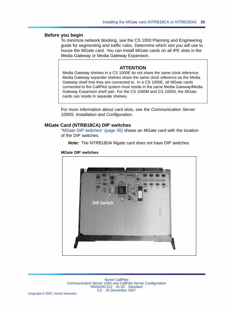
MGate Card (NTRB18CA) DIP switches"MGate DIP switches" (page 35) shows an MGate card with the locationof the DIP switches.
Note: The NTRB18DA Mgate card does not have DIP switches.
MGate DIP switches
Nortel CallPilotCommunication Server 1000 and CallPilot Server Configuration
NN44200-312 01.03 Standard5.0 20 December 2007
Copyright © 2007, Nortel Networks
.

36 Chapter 3 Connecting the CallPilot server to the CS 1000 system
To set the DIP switches for the MGate card (NTRB18CA only)
Step Action
1 Remove the MGate card from its protective sleeve.
2 Set the DIP switches on the MGate card as shown in "MGate DIPswitch settings" (page 36). These DIP switch settings are used forall MGate cards and all system configurations.
MGate DIP switch settings
1 2 3 4 5 6 7 8
ON X X X X
OFF X X X X
—End—
To install the MGate card
Step Action
1 Remove the Media Gateway or Media Gateway Expansion cover.
2 Ensure that the slot in which you are installing the MGate does notalready have a cable connected.
3 Press and pull the top and bottom latches on the MGate cardoutward to open the latches for installation of the card.
A hook on the bottom of the latch must clear a small pin to open.see "Media Gateway slot latch" (page 37).
Nortel CallPilotCommunication Server 1000 and CallPilot Server Configuration
NN44200-312 01.03 Standard5.0 20 December 2007
Copyright © 2007, Nortel Networks
.

Installing the MGate card (NTRB18CA or NTRB18DA) 37
Media Gateway slot latch
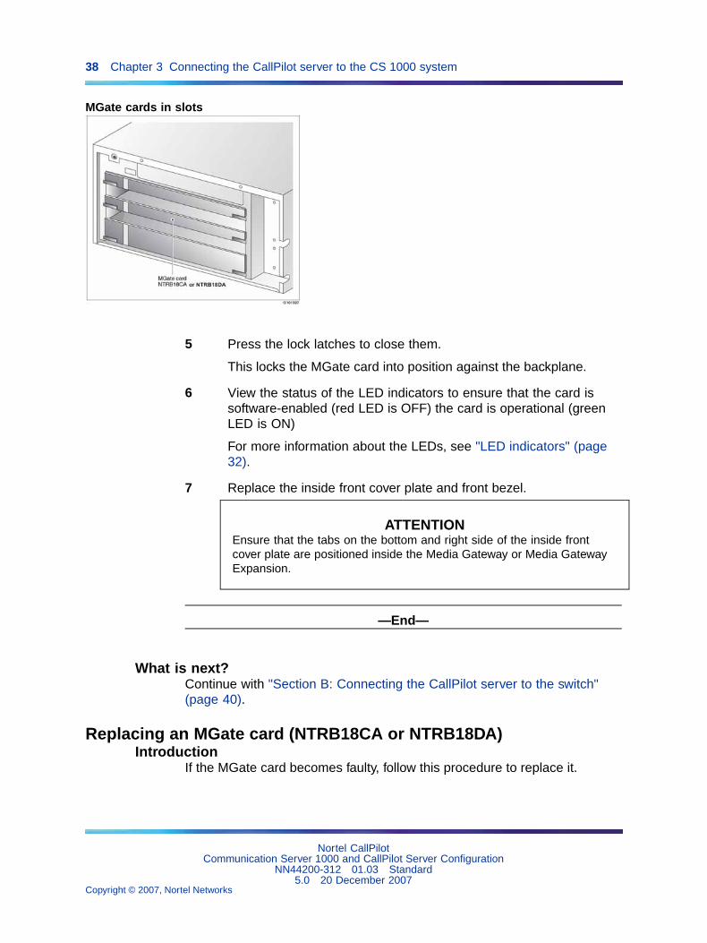
4 Slide the MGate card into an unoccupied slot.
When correctly inserted, the top of the MGate card is on the left.See the following diagram.
Nortel CallPilotCommunication Server 1000 and CallPilot Server Configuration
NN44200-312 01.03 Standard5.0 20 December 2007
Copyright © 2007, Nortel Networks
.
38 Chapter 3 Connecting the CallPilot server to the CS 1000 system
MGate cards in slots
5 Press the lock latches to close them.
This locks the MGate card into position against the backplane.
6 View the status of the LED indicators to ensure that the card issoftware-enabled (red LED is OFF) the card is operational (greenLED is ON)
For more information about the LEDs, see "LED indicators" (page32).
7 Replace the inside front cover plate and front bezel.
ATTENTIONEnsure that the tabs on the bottom and right side of the inside frontcover plate are positioned inside the Media Gateway or Media GatewayExpansion.
—End—
What is next?Continue with "Section B: Connecting the CallPilot server to the switch"(page 40).
Replacing an MGate card (NTRB18CA or NTRB18DA)Introduction
If the MGate card becomes faulty, follow this procedure to replace it.
Nortel CallPilotCommunication Server 1000 and CallPilot Server Configuration
NN44200-312 01.03 Standard5.0 20 December 2007
Copyright © 2007, Nortel Networks
.
Replacing an MGate card (NTRB18CA or NTRB18DA) 39
To replace an MGate card
Note: You do not need to power down the switch for this procedure asthe MGate card is hot-swappable.
Step Action
1 Courtesy stop the DS0 channels from the CallPilot administrative PCto stop all call processing gracefully.
To do this, use the Channel Monitor or the Maintenance page inCallPilot Manager, as described in the CallPilot Server Maintenanceand Diagnostics guide for your server.
Note: If your system has multiple MGate cards, you can chooseto courtesy stop only the DS30X channels that belong to theMGate card that is being replaced.
2 Remove the switch’s front cover to expose the shelf slots.
3 Open the latches to unlock the faulty MGate card.
4 Remove the faulty MGate card from the switch.
5 Press the replacement MGate into the same slot that the faultyMGate card occupied.
Note: Note: If you place the MGate card in a new slot, thenyou must do the following:
a. Reprogram the switch to account for the new slot number.
b. Move the DS30X cable to the new slot.
c. Reconfigure the software from the CallPilot administrative clientPC.
6 Press the latches on the top and bottom of the MGate card to closethem.
Result: Result: This locks the card into position against thebackplane.
7 View the status of the LED indicators to ensure that the card issoftware-enabled (red LED is OFF), and the card is operational(green LED is ON).
8 Re-enable the DS0 channels that were disabled before the cardwas removed.
To do this, use the Channel Monitor or the Maintenance page inCallPilot Manager, as described in the CallPilot Server Maintenanceand Diagnostics guide for your server.
Nortel CallPilotCommunication Server 1000 and CallPilot Server Configuration
NN44200-312 01.03 Standard5.0 20 December 2007
Copyright © 2007, Nortel Networks
.
40 Chapter 3 Connecting the CallPilot server to the CS 1000 system
—End—
Section B: Connecting the CallPilot server to the switch
In this section"About the DS30X cable" (page 40)
"Connecting MPB16-4 boards to MGate cards (NTRB18CA or NTRB18DA)"(page 42)
"Connecting the MPB96 boards to MGate cards (NTRB18CA orNTRB18DA)" (page 47)
About the DS30X cableIntroduction
The MGate card (NTRB18CA or NTRB18DA) ships from the factory with theDS30X cables required by the MPB board that is installed in the server.
CAUTIONRisk of data lossDo not substitute other versions of these boards and cables inthe configurations specified in this documentation, as this canresult in data loss.
DS30X cables supported by MPB16-4 boardsThe DS30X cable that establishes the connection between the MPB16-4boards and the MGate cards is 10 m (30 ft) long. Therefore, the CallPilotserver must be placed within 10 m (30 ft) of the Media Gateway or MediaGateway Expansion.
Nortel CallPilotCommunication Server 1000 and CallPilot Server Configuration
NN44200-312 01.03 Standard5.0 20 December 2007
Copyright © 2007, Nortel Networks
.
About the DS30X cable 41
the server isequipped with the DS30X cable is an
one MPB16-4board NTRH2012 cable.
This is a single DS30X cable that connects oneMPB16-4 board to one MGate card.
more than one MPB16-4 board NTRH2013 cable.
This is a dual DS30X cable that connects thefirst of two MPB16-4 boards to two MGatecards. The connectors on the NTRH2013dual DS30X cable are labeled DS30X-1 andDS30X-2.
Note: The NTRH2012 and NTRH2013 cables contain ferrites that control EMCemission levels. Do not remove them.
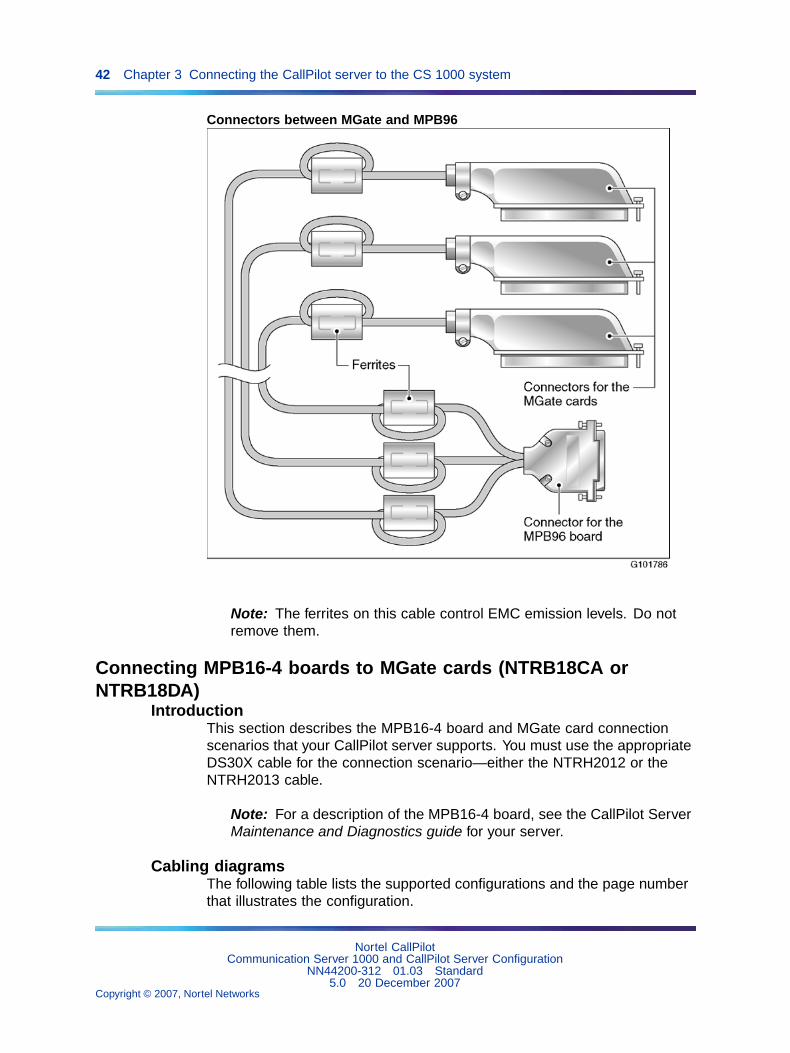
DS30X cable supported by the MPB96 boardThe NTRH2014 cable is a triple DS30X cable that connects the first MPB96board to up to three MGate cards. The cable is 20 m (60 ft) long, whichallows you to install the CallPilot server in a different room from the MediaGateway or Media Gateway Expansion.
One end of the cable has a 44-pin connector that connects to the MPB96board’s faceplate. If the server is equipped with more than one MPB96board, the cable connects to the first board (the board in the lowestnumbered slot of the server).
The other end of the cable has three 50-pin connectors that connect toMGate cards. The MGate connectors are labeled DS30X-1, DS30X-2, andDS30X-3. See "Connectors between MGate and MPB96" (page 42).
Nortel CallPilotCommunication Server 1000 and CallPilot Server Configuration
NN44200-312 01.03 Standard5.0 20 December 2007
Copyright © 2007, Nortel Networks
.
42 Chapter 3 Connecting the CallPilot server to the CS 1000 system
Connectors between MGate and MPB96
Note: The ferrites on this cable control EMC emission levels. Do notremove them.
Connecting MPB16-4 boards to MGate cards (NTRB18CA orNTRB18DA)
IntroductionThis section describes the MPB16-4 board and MGate card connectionscenarios that your CallPilot server supports. You must use the appropriateDS30X cable for the connection scenario—either the NTRH2012 or theNTRH2013 cable.
Note: For a description of the MPB16-4 board, see the CallPilot ServerMaintenance and Diagnostics guide for your server.
Cabling diagramsThe following table lists the supported configurations and the page numberthat illustrates the configuration.
Nortel CallPilotCommunication Server 1000 and CallPilot Server Configuration
NN44200-312 01.03 Standard5.0 20 December 2007
Copyright © 2007, Nortel Networks
.

Connecting MPB16-4 boards to MGate cards (NTRB18CA or NTRB18DA) 43
Cabling configurations
Number ofchannels
Number ofMPB16-4 boards
Number ofMGate cards See
32 or less 1 1
32 or less 2 1
48 or less 1 2
48 or less 2 2
Identifying the location of MPB 1 and MPB 2In the cabling diagrams, the terms MPB16-4 #1 and MPB16-4 #2 are usedto identify the two MPB16-4 boards. The table below indicates the locationof these boards.
MPB16-4 slot locations
MPB Number 1002rp server
MPB16-4 #1 slot 11
MPB16-4 #2 slot 12
Note: On the 1002rp servers, MPB16-4 #1 is the MPB16-4 boardclosest to the SBC card. For more information on slot assignments, seethe slot assignment tables in the CallPilot Server Hardware Installationguide for your server.
Identifying the location of MGate 1, 2, and 3In the cabling diagrams, the terms MGate #1, MGate #2, and MGate #3identify the MGate cards. MGate #1 is in the lowest-numbered slot in theMedia Gateway or Media Gateway Expansion. MGate #2 and MGate #3are in the next available higher slots.
One MPB16-4 board and one MGate card (32 channels or less)Use the single cable (NTRH2012) to connect the MPB16-4 board to theMGate card. See "MGate cabling for the 1002rp server" (page 44).
Nortel CallPilotCommunication Server 1000 and CallPilot Server Configuration
NN44200-312 01.03 Standard5.0 20 December 2007
Copyright © 2007, Nortel Networks
.
44 Chapter 3 Connecting the CallPilot server to the CS 1000 system
MGate cabling for the 1002rp server
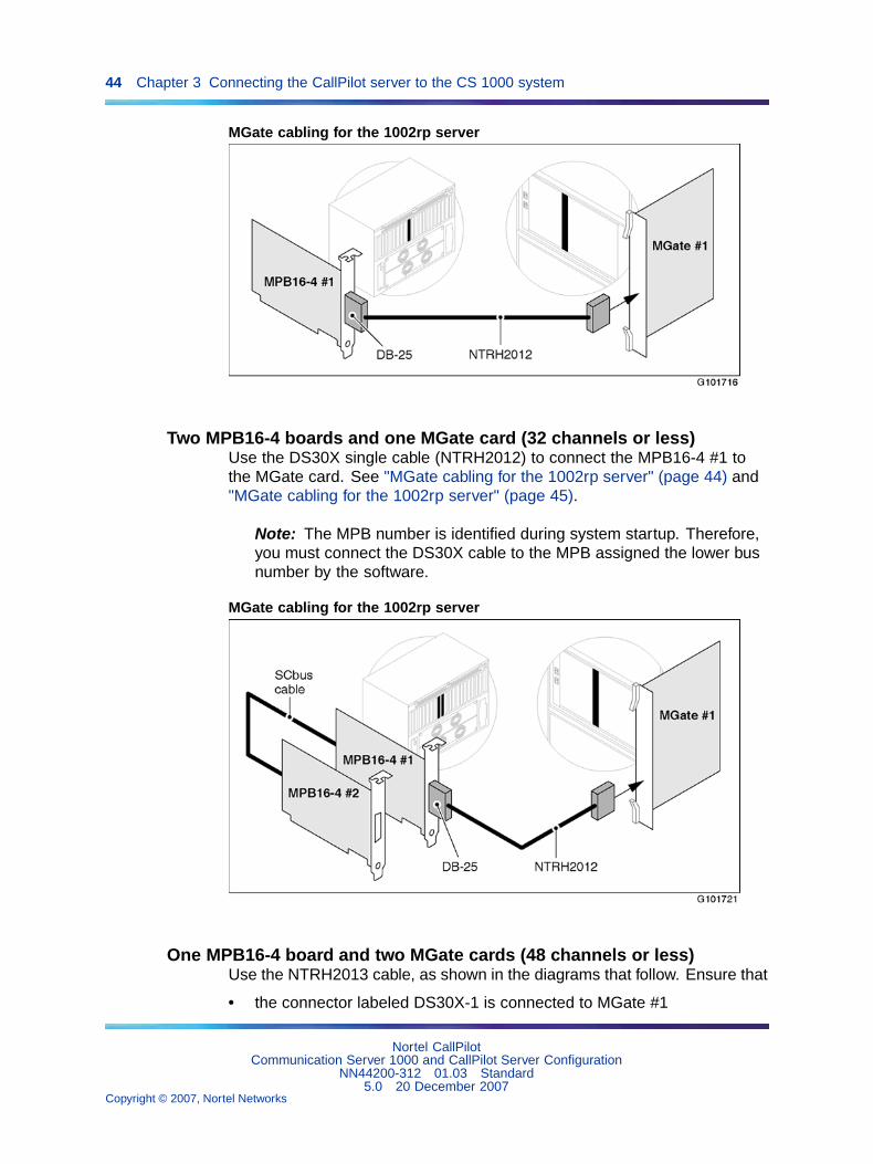
Two MPB16-4 boards and one MGate card (32 channels or less)Use the DS30X single cable (NTRH2012) to connect the MPB16-4 #1 tothe MGate card. See "MGate cabling for the 1002rp server" (page 44) and"MGate cabling for the 1002rp server" (page 45).
Note: The MPB number is identified during system startup. Therefore,you must connect the DS30X cable to the MPB assigned the lower busnumber by the software.
MGate cabling for the 1002rp server
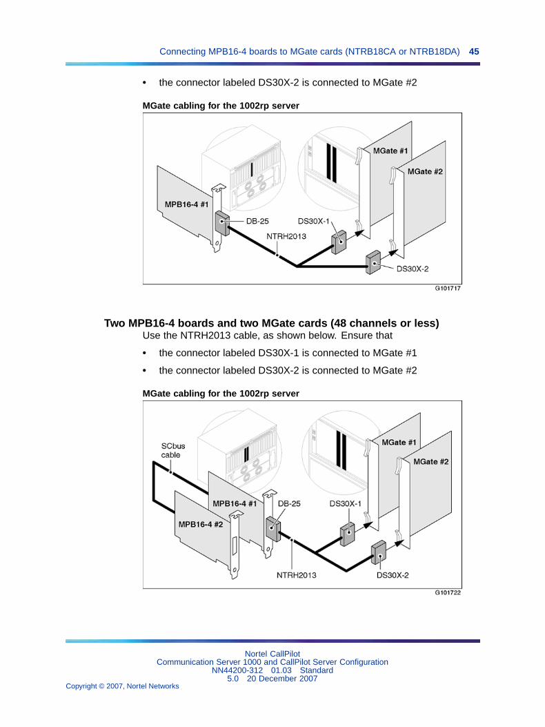
One MPB16-4 board and two MGate cards (48 channels or less)Use the NTRH2013 cable, as shown in the diagrams that follow. Ensure that
• the connector labeled DS30X-1 is connected to MGate #1
Nortel CallPilotCommunication Server 1000 and CallPilot Server Configuration
NN44200-312 01.03 Standard5.0 20 December 2007
Copyright © 2007, Nortel Networks
.
Connecting MPB16-4 boards to MGate cards (NTRB18CA or NTRB18DA) 45
• the connector labeled DS30X-2 is connected to MGate #2
MGate cabling for the 1002rp server
Two MPB16-4 boards and two MGate cards (48 channels or less)Use the NTRH2013 cable, as shown below. Ensure that
• the connector labeled DS30X-1 is connected to MGate #1
• the connector labeled DS30X-2 is connected to MGate #2
MGate cabling for the 1002rp server
Nortel CallPilotCommunication Server 1000 and CallPilot Server Configuration
NN44200-312 01.03 Standard5.0 20 December 2007
Copyright © 2007, Nortel Networks
.
46 Chapter 3 Connecting the CallPilot server to the CS 1000 system
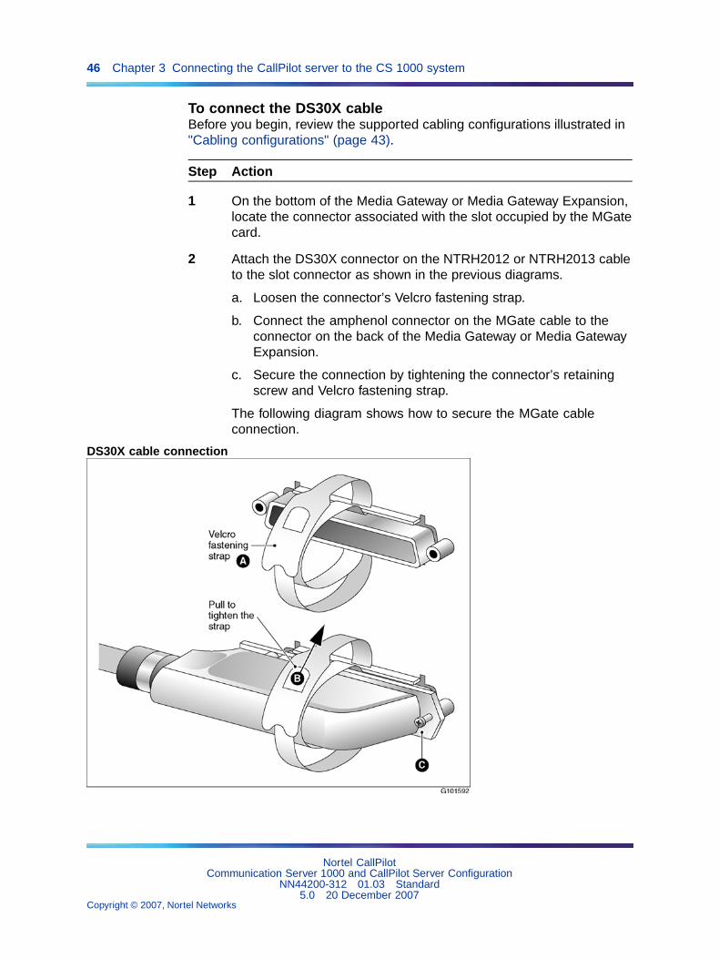
To connect the DS30X cableBefore you begin, review the supported cabling configurations illustrated in"Cabling configurations" (page 43).
Step Action
1 On the bottom of the Media Gateway or Media Gateway Expansion,locate the connector associated with the slot occupied by the MGatecard.
2 Attach the DS30X connector on the NTRH2012 or NTRH2013 cableto the slot connector as shown in the previous diagrams.
a. Loosen the connector’s Velcro fastening strap.
b. Connect the amphenol connector on the MGate cable to theconnector on the back of the Media Gateway or Media GatewayExpansion.
c. Secure the connection by tightening the connector’s retainingscrew and Velcro fastening strap.
The following diagram shows how to secure the MGate cableconnection.
DS30X cable connection
Nortel CallPilotCommunication Server 1000 and CallPilot Server Configuration
NN44200-312 01.03 Standard5.0 20 December 2007
Copyright © 2007, Nortel Networks
.

Connecting the MPB96 boards to MGate cards (NTRB18CA or NTRB18DA) 47
3 Connect the other end of the MGate cable to the MPB16-4 board’sconnector on the bottom of the CallPilot server.
—End—
What is next?Continue with Chapter 4 "Configuring the CS 1000 system" (page 51).
Connecting the MPB96 boards to MGate cards (NTRB18CA orNTRB18DA)
IntroductionThe CallPilot server ships from the factory with one or more MPB96 boardsalready installed. Because the MPB96 board is already installed in theserver, you only need to connect it to the MGate card in the CS 1000 systemwith the NTRH2014 DS30X cable.
You connect the MPB96 board to up to three MGate cards depending on thenumber of DS0 channels. If fewer than three MGate cards are present, youcan leave the unused parts of the NTRH2014 cable unconnected.
Note: For a description of the MPB96 board, see the CallPilot ServerMaintenance and Diagnostics guide for your server.
MGate cabling for the 703t, 600r, 1002rp, and 1005r serversOne MPB96 board and three MGate cards (up to 96 channels)
Nortel CallPilotCommunication Server 1000 and CallPilot Server Configuration
NN44200-312 01.03 Standard5.0 20 December 2007
Copyright © 2007, Nortel Networks
.
48 Chapter 3 Connecting the CallPilot server to the CS 1000 system
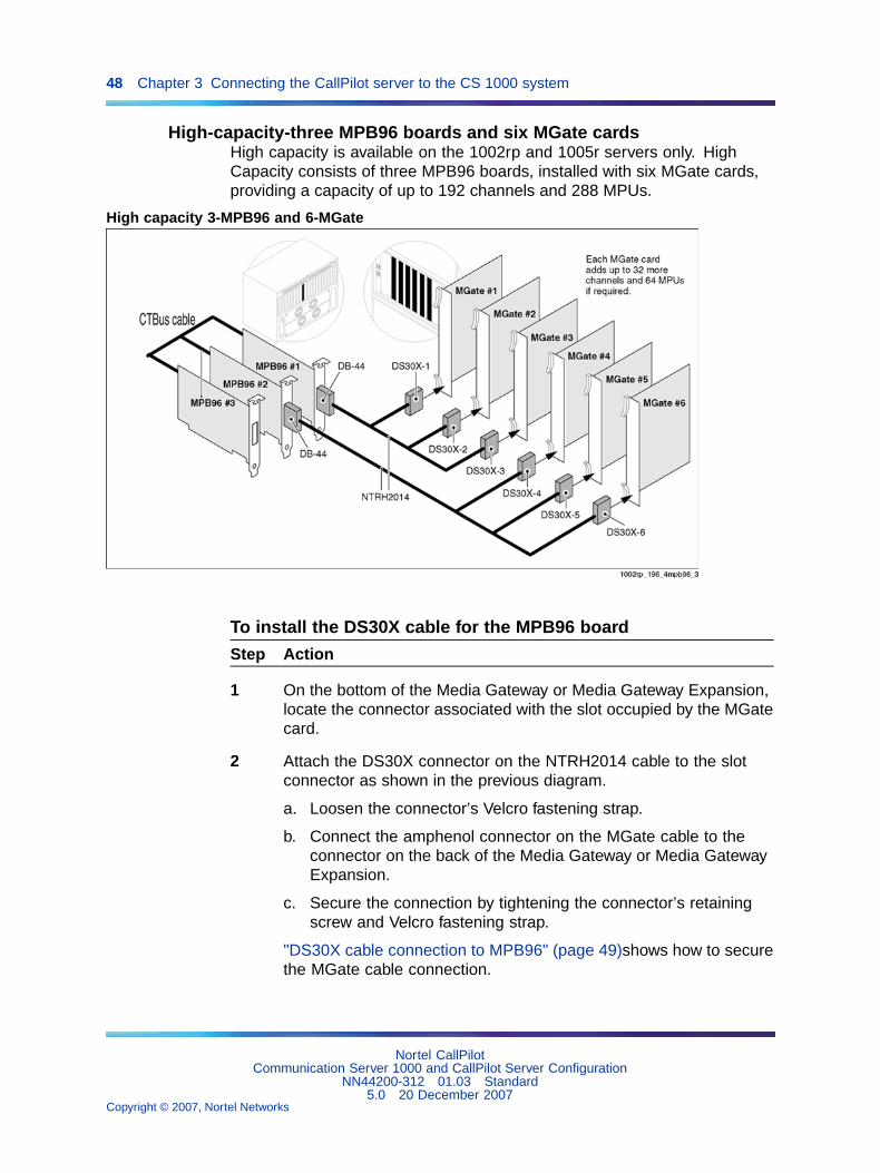
High-capacity-three MPB96 boards and six MGate cardsHigh capacity is available on the 1002rp and 1005r servers only. HighCapacity consists of three MPB96 boards, installed with six MGate cards,providing a capacity of up to 192 channels and 288 MPUs.
High capacity 3-MPB96 and 6-MGate
To install the DS30X cable for the MPB96 board
Step Action
1 On the bottom of the Media Gateway or Media Gateway Expansion,locate the connector associated with the slot occupied by the MGatecard.
2 Attach the DS30X connector on the NTRH2014 cable to the slotconnector as shown in the previous diagram.
a. Loosen the connector’s Velcro fastening strap.
b. Connect the amphenol connector on the MGate cable to theconnector on the back of the Media Gateway or Media GatewayExpansion.
c. Secure the connection by tightening the connector’s retainingscrew and Velcro fastening strap.
"DS30X cable connection to MPB96" (page 49)shows how to securethe MGate cable connection.
Nortel CallPilotCommunication Server 1000 and CallPilot Server Configuration
NN44200-312 01.03 Standard5.0 20 December 2007
Copyright © 2007, Nortel Networks
.
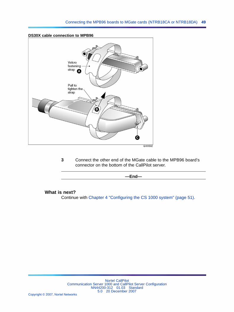
Connecting the MPB96 boards to MGate cards (NTRB18CA or NTRB18DA) 49
DS30X cable connection to MPB96
3 Connect the other end of the MGate cable to the MPB96 board’sconnector on the bottom of the CallPilot server.
—End—
What is next?Continue with Chapter 4 "Configuring the CS 1000 system" (page 51).
Nortel CallPilotCommunication Server 1000 and CallPilot Server Configuration
NN44200-312 01.03 Standard5.0 20 December 2007
Copyright © 2007, Nortel Networks
.

50 Chapter 3 Connecting the CallPilot server to the CS 1000 system
Nortel CallPilotCommunication Server 1000 and CallPilot Server Configuration
NN44200-312 01.03 Standard5.0 20 December 2007
Copyright © 2007, Nortel Networks
.
51
Chapter 4Configuring the CS 1000 system
In this chapter"CS 1000 hardware and software requirements" (page 52)
"CS 1000 configuration checklist" (page 52)
"Provisioning the ELAN subnet" (page 56)
"Defining the Message Register for AML message tracing" (page 58)
"Configuring CS 1000 IP addresses and enabling the Ethernet interface"(page 59)
"Defining CallPilot in the customer data block" (page 62)
"Configuring the ACD agent queue" (page 67)
"Configuring ACD agents" (page 68)
"Enabling the card slots" (page 70)
"Defining the default ACD DN" (page 71)
"Configuring CDN queues for messaging services" (page 72)
"Configuring phantom DNs" (page 73)
"Configuring dummy ACD DNs" (page 76)
"Provisioning user phonesets" (page 77)
"Configuring the route data block for Network Message Service" (page 80)
Nortel CallPilotCommunication Server 1000 and CallPilot Server Configuration
NN44200-312 01.03 Standard5.0 20 December 2007
Copyright © 2007, Nortel Networks
.
52 Chapter 4 Configuring the CS 1000 system
"Saving CS 1000 changes" (page 81)
CS 1000 hardware and software requirementsRequired hardware
To support connectivity to tower and rackmount CallPilot servers, youmust install one or more MGate cards (NTRB18CA or NTRB18DA) in theMedia Gateway or Media Gateway Expansion, as described in "Section A:Installing the MGate card" (page 31).
ATTENTIONAn MGate card (NTRB18CA or NTRB18DA) is not used with the 201i server.
Required CS 1000 system softwareTo support the CallPilot 201i server, the CS 1000 system requires softwarerelease X21 Release 3.0 or later.
To support the CallPilot 600r, 703t, 1002rp, or 1005r servers, the CS 1000system requires software release X21 Release 3.0 or later.
Required X21 PEPsCheck the CallPilot Distributor Technical Reference (DTR) athttp://my.nortel.com for required X21 PEPs.
You require a user name and password to access this site.
X21 PEPs are available only on the Meridian* PEP Library (MPL) web site at:https://transportvo.nortel.com/mpl/mpl
If you cannot access the Meridian PEP Library, or if you cannot find theService Updates (SUs), check the CallPilot Distributor Technical Reference,or contact your Nortel representative.
The Meridian PEP Library is a secure web site requiring a user name and apassword to log on. If you do not have an account, you must apply for one.It can take up to 72 hours to process your account request.
CS 1000 configuration checklistIntroduction
The following checklist provides a list of the tasks you must complete forcorrect CallPilot and CS 1000 system interoperation. Detailed instructionsare provided for each task, as indicated, in the remainder of this chapter.
Nortel CallPilotCommunication Server 1000 and CallPilot Server Configuration
NN44200-312 01.03 Standard5.0 20 December 2007
Copyright © 2007, Nortel Networks
.
CS 1000 configuration checklist 53
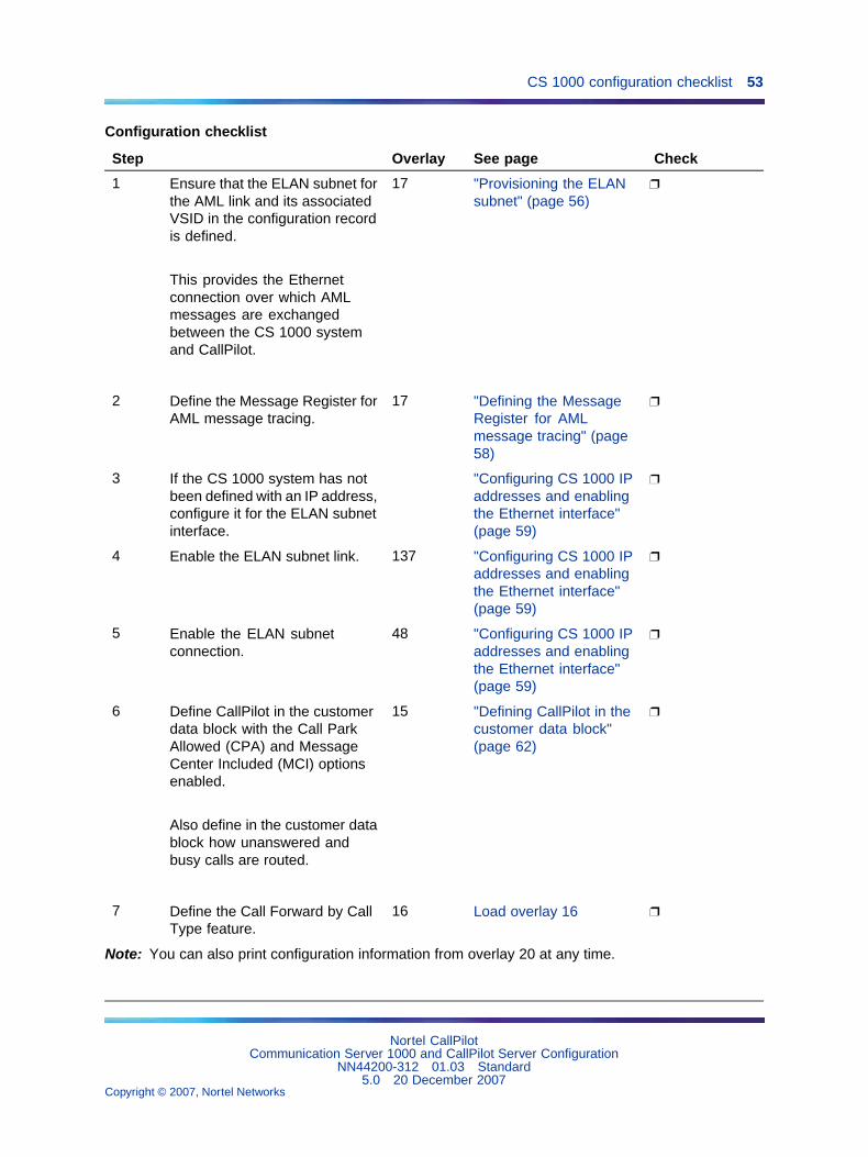
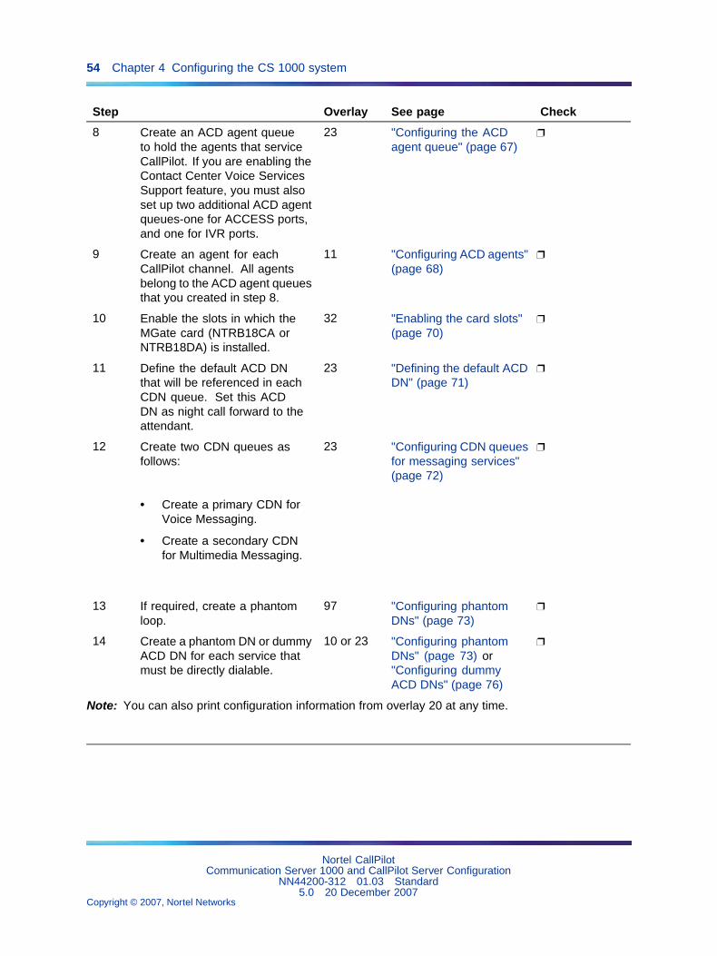
Configuration checklist
Step Overlay See page Check
1 Ensure that the ELAN subnet forthe AML link and its associatedVSID in the configuration recordis defined.
This provides the Ethernetconnection over which AMLmessages are exchangedbetween the CS 1000 systemand CallPilot.
17 "Provisioning the ELANsubnet" (page 56)
2 Define the Message Register forAML message tracing.
17 "Defining the MessageRegister for AMLmessage tracing" (page58)
3 If the CS 1000 system has notbeen defined with an IP address,configure it for the ELAN subnetinterface.
"Configuring CS 1000 IPaddresses and enablingthe Ethernet interface"(page 59)
4 Enable the ELAN subnet link. 137 "Configuring CS 1000 IPaddresses and enablingthe Ethernet interface"(page 59)
5 Enable the ELAN subnetconnection.
48 "Configuring CS 1000 IPaddresses and enablingthe Ethernet interface"(page 59)
6 Define CallPilot in the customerdata block with the Call ParkAllowed (CPA) and MessageCenter Included (MCI) optionsenabled.
Also define in the customer datablock how unanswered andbusy calls are routed.
15 "Defining CallPilot in thecustomer data block"(page 62)
7 Define the Call Forward by CallType feature.
16 Load overlay 16
Note: You can also print configuration information from overlay 20 at any time.
Nortel CallPilotCommunication Server 1000 and CallPilot Server Configuration
NN44200-312 01.03 Standard5.0 20 December 2007
Copyright © 2007, Nortel Networks
.
54 Chapter 4 Configuring the CS 1000 system
Step Overlay See page Check
8 Create an ACD agent queueto hold the agents that serviceCallPilot. If you are enabling theContact Center Voice ServicesSupport feature, you must alsoset up two additional ACD agentqueues-one for ACCESS ports,and one for IVR ports.
23 "Configuring the ACDagent queue" (page 67)
9 Create an agent for eachCallPilot channel. All agentsbelong to the ACD agent queuesthat you created in step 8.
11 "Configuring ACD agents"(page 68)
10 Enable the slots in which theMGate card (NTRB18CA orNTRB18DA) is installed.
32 "Enabling the card slots"(page 70)
11 Define the default ACD DNthat will be referenced in eachCDN queue. Set this ACDDN as night call forward to theattendant.
23 "Defining the default ACDDN" (page 71)
12 Create two CDN queues asfollows:
• Create a primary CDN forVoice Messaging.
• Create a secondary CDNfor Multimedia Messaging.
23 "Configuring CDN queuesfor messaging services"(page 72)
13 If required, create a phantomloop.
97 "Configuring phantomDNs" (page 73)
14 Create a phantom DN or dummyACD DN for each service thatmust be directly dialable.
10 or 23 "Configuring phantomDNs" (page 73) or"Configuring dummyACD DNs" (page 76)
Note: You can also print configuration information from overlay 20 at any time.
Nortel CallPilotCommunication Server 1000 and CallPilot Server Configuration
NN44200-312 01.03 Standard5.0 20 December 2007
Copyright © 2007, Nortel Networks
.
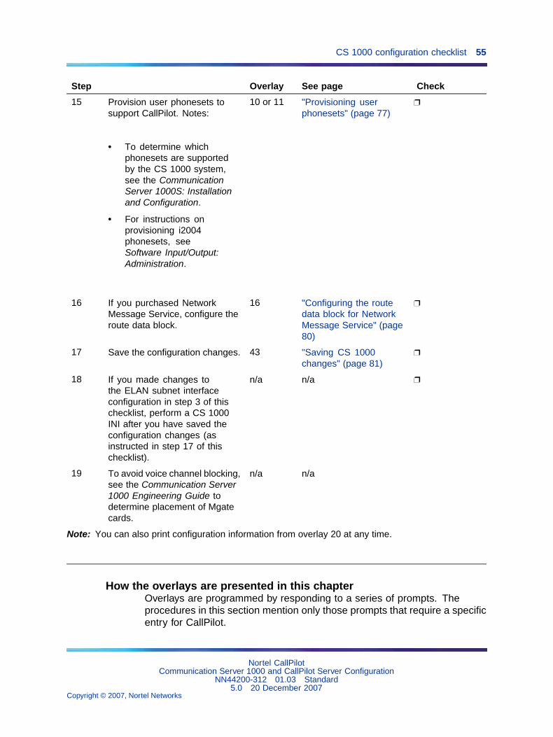
CS 1000 configuration checklist 55
Step Overlay See page Check
15 Provision user phonesets tosupport CallPilot. Notes:
• To determine whichphonesets are supportedby the CS 1000 system,see the CommunicationServer 1000S: Installationand Configuration.
• For instructions onprovisioning i2004phonesets, seeSoftware Input/Output:Administration.
10 or 11 "Provisioning userphonesets" (page 77)
16 If you purchased NetworkMessage Service, configure theroute data block.
16 "Configuring the routedata block for NetworkMessage Service" (page80)
17 Save the configuration changes. 43 "Saving CS 1000changes" (page 81)
18 If you made changes tothe ELAN subnet interfaceconfiguration in step 3 of thischecklist, perform a CS 1000INI after you have saved theconfiguration changes (asinstructed in step 17 of thischecklist).
n/a n/a
19 To avoid voice channel blocking,see the Communication Server1000 Engineering Guide todetermine placement of Mgatecards.
n/a n/a
Note: You can also print configuration information from overlay 20 at any time.
How the overlays are presented in this chapterOverlays are programmed by responding to a series of prompts. Theprocedures in this section mention only those prompts that require a specificentry for CallPilot.
Nortel CallPilotCommunication Server 1000 and CallPilot Server Configuration
NN44200-312 01.03 Standard5.0 20 December 2007
Copyright © 2007, Nortel Networks
.
56 Chapter 4 Configuring the CS 1000 system
You can program other prompts if necessary for your site. To accept thedefault value for other prompts, press Enter.
ATTENTIONEnsure that you update the CS 1000 database when you finish making changes,as described in "Saving CS 1000 changes" (page 81).
Working with overlaysWhen you work with overlays, follow these general steps:
1. Load the appropriate overlay.
2. Respond to the prompts as shown in the tables in this section. PressEnter after each prompt until you reach the next one that you mustdefine for CallPilot.
3. When you complete the configuration, type **** in response to the REQprompt.
The customer numberCallPilot can only be provided on a per customer basis on the CS 1000system. AML messages used for communications between the CS 1000system and CallPilot contain a customer number to which CallPilot belongs.
ATTENTIONWhen you type the customer number in the overlays, ensure that it is the correctcustomer number.
Provisioning the ELAN subnetIntroduction
Define and configure the ELAN subnet for the AML link and its associatedVSID in the configuration record. This provides the Ethernet connectionover which AML messages are exchanged between the CS 1000 systemand CallPilot.
To provision the ELAN subnet
Step Action
1 Load overlay 17.
2 For each prompt listed below, type the response indicated. Forthose prompts that are not listed, you can accept the default bypressing Enter.
Prompt Response Description
REQ CHG Change
Nortel CallPilotCommunication Server 1000 and CallPilot Server Configuration
NN44200-312 01.03 Standard5.0 20 December 2007
Copyright © 2007, Nortel Networks
.

Provisioning the ELAN subnet 57
Prompt Response Description
TYPE ADAN Action device and number
ADAN NEW ELAN xx Configure a new link and assign it anumber, where xx is within the ELANsubnet range (16-31). You can useany number in this range as long as itis not already used.
CTYP ELAN Card type
DES x...x type a designator to identify this ELANsubnet.
REQ CHG Change
TYPE VAS Value added server configuration
VAS new Configure a new AML link or changethe existing link configuration.
VSID yy The VAS identifier can be in the rangeof 16-31. For convenience, this can bethe same number you assigned to thenew ELAN subnet link (in response tothe ADAN prompt).
ELAN xx This should be the same numberdefined in ADAN.
SECU x...x If you have Contact Center connectedto your switch, choose YES (even ifyou are not using Contact Center VoiceServices Support).
REQ CHG Change
TYPE PARM System parameters
NCR x...x Number of call registers (rangedepends on system type). Incrementthe current value by 2 x the number ofCallPilot DS0 channels.
For example, if the current NCR valueis 500 and there are 24 DS0 channels,change the NCR value to 548.
Nortel CallPilotCommunication Server 1000 and CallPilot Server Configuration
NN44200-312 01.03 Standard5.0 20 December 2007
Copyright © 2007, Nortel Networks
.
58 Chapter 4 Configuring the CS 1000 system
Prompt Response Description
CSQI (20) to 255 Maximum number of call registers forCSL input queues. Set this parameterto 2 x the number of
CallPilot DS0 channels. For example,if there are 24 DS0 channels, type 48.
CSQO (20) to 255 Maximum number of call registersfor CSL/AML output queues. Setthis parameter to 2 x the number ofCallPilot DS0 channels.
For example, if there are 24 DS0channels, type 48.
<Enter> Press Enter until you reach the end ofthe overlay (REQ prompt).
REQ **** Exits the overlay.
—End—
Defining the Message Register for AML message tracingIntroduction
This section provides instructions for updating the Message Register(MGCR) parameter. The MGCR parameter affects the AML output whenmessage tracing is turned on for the ELAN subnet.
ATTENTIONThe MGCR parameter is used by your Nortel customer support representativeto troubleshoot your CallPilot and CS 1000. This parameter is not required fornormal day-to-day CallPilot operation.
To define the MGCR parameter
Step Action
1 Load overlay 17.
2 For each prompt listed below, type the response indicated. Forthose prompts that are not listed, you can accept the default bypressing Enter.
Nortel CallPilotCommunication Server 1000 and CallPilot Server Configuration
NN44200-312 01.03 Standard5.0 20 December 2007
Copyright © 2007, Nortel Networks
.

Configuring CS 1000 IP addresses and enabling the Ethernet interface 59
Prompt Response Description
REQ CHG Change
TYPE PARM System parameters
MGCR 0 to NCR Maximum number of call registers usedby AUX messaging.
The recommended value for CallPilotis 25.
REQ **** Exits the overlay.
—End—
Configuring CS 1000 IP addresses and enabling the Ethernetinterface
IntroductionIf the CS 1000 system has not been defined with the necessary IP addressinformation (see below), configure the IP addresses for the Ethernetinterface. You must also enable the Ethernet interface, as described inthis section.
Notes:
• The CS 1000 system has dual CPUs.
• If the CS 1000 system is also connected to a Nortel Server Subnet (NSSubnet), you must define a gateway IP address.
ATTENTIONTo change an IP address after CallPilot is installed and running, you must dothe following:
1 Courtesy stop and shut down CallPilot.
2 Change the IP addresses on the switch, as described in this section.
3 Restart CallPilot.
4 Rerun the CallPilot Configuration Wizard to update the switch IP addressinformation.
To configure the IP addresses and enable the Ethernet interfaceThe following data is used in examples in this procedure:
Nortel CallPilotCommunication Server 1000 and CallPilot Server Configuration
NN44200-312 01.03 Standard5.0 20 December 2007
Copyright © 2007, Nortel Networks
.

60 Chapter 4 Configuring the CS 1000 system
Data Value (examples only)
Primary IP address 47.1.1.10
Primary Host Name PRIMARY_HOST
Subnet mask 255.255.255.0
Default gateway IP address 47.1.1.1
Network IP address 0.0.0.0
Step Action
1 Load overlay 117.
2 Perform the following substeps to check the current IP addresses tosee if they already match what you plan to configure for CallPilot.
If the current values displayed by the following commands must beupdated, then continue with the remaining steps in this procedure.Otherwise, go to step 15.
a. Type PRT HOST and press Enter.
b. Type STAT HOST and press Enter.
c. Type PRT MASK and press Enter.
d. Type PRT ELNK and press Enter.
3 Load overlay 137.
4 Type DIS ELNK and press Enter.
5 Type STAT ELNK and press Enter.
6 Confirm that the system displays ELNK DISABLED.
7 Load overlay 117.
8 Create a host entry for the primary IP address by typing the followingcommand:
NEW HOST NAME xxx.xxx.xxx.xxx (where NAME is the host namefor the primary IP address, and xxx.xxx.xxx.xxx is the primary IPaddress)
Example: NEW HOST PRIMARY_HOST 47.1.1.10
9 If the CS 1000 system is connected to a Nortel Server Subnet (NSSubnet), create a host entry for the gateway IP address by typingthe following command:
Nortel CallPilotCommunication Server 1000 and CallPilot Server Configuration
NN44200-312 01.03 Standard5.0 20 December 2007
Copyright © 2007, Nortel Networks
.

Configuring CS 1000 IP addresses and enabling the Ethernet interface 61
NEW HOST NAME xxx.xxx.xxx.xxx (where NAME is the host namefor the gateway IP address, and xxx.xxx.xxx.xxx is the gateway IPaddress)
Example: NEW HOST GATEWAY 47.1.1.1
10 Assign a host to the primary IP address by typing the followingcommand:
CHG ELNK ACTIVE NAME (where NAME is the host name for theprimary IP address)
Example: CHG ELNK ACTIVE PRIMARY_HOST (entry for primaryhost)
11 Set up the Ethernet subnet mask by typing the following command:
CHG MASK xxx.xxx.xxx.xxx (where xxx.xxx.xxx.xxx is the subnetmask)
Example: CHG MASK 255.255.255.0
12 If using a gateway, ensure that the routing entry is set up andenabled. If the route has been set up previously, go to step 13.Otherwise, set up and enable the routing entry as follows:
a. Set up the routing entry by typing the following command:
NEW ROUTE xxx.xxx.xxx.xxx yyy.yyy.yyy.yyy (wherexxx.xxx.xxx.xxx is the network IP address and yyy.yyy.yyy.yyy isthe gateway IP address; put one space between the network IPaddress and the gateway IP address)
Example: NEW ROUTE 0.0.0.0 47.1.1.1
b. Enable the route by typing the following command:
ENL ROUTE x (where x is the number assigned to the ROUTEentry)
13 Update the INET database by typing the following command:UPDATEDBS
14 Type **** and press Enter to exit the overlay.
15 Load overlay 137.
16 Type STAT ELNK and press Enter.
17 If the system displays ELNK ENABLED, then go to step 18. If thesystem displays ELNK DISABLED, then do the following substeps:
a. Type ENL ELNK and press Enter.
b. Type STAT ELNK and press Enter.
Nortel CallPilotCommunication Server 1000 and CallPilot Server Configuration
NN44200-312 01.03 Standard5.0 20 December 2007
Copyright © 2007, Nortel Networks
.
62 Chapter 4 Configuring the CS 1000 system
c. Confirm that the system displays ELNK ENABLED. Then go tostep 18.
18 Load overlay 48.
19 Type STAT ELAN and press Enter.
20 If the system displays ELAN ENABLED, then go to step 21. If thesystem displays ELAN DISABLED, then do the following substeps:
a. Type ENL ELAN and press Enter.
b. Type STAT ELAN and press Enter.
c. Confirm that the system displays ELAN ENABLED. Then go tostep 21.
21 Load overlay 117.
22 Verify the changes as follows:
a. Type PRT HOST and press Enter.
b. Type STAT HOST and press Enter.
c. Type PRT MASK and press Enter.
—End—
Defining CallPilot in the customer data blockIntroduction
You must define the CallPilot service in the customer data block, with the CallPark Allowed (CPA) and Message Center Included (MCI) options enabled.
During this configuration, you also define how unanswered and busy callsare routed:
• Flexible Call Forward (FNAD/FNAN/FNAL) is set on a per customerbasis. Define the call forward DN in the user’s phoneset data.
• Call Forward No Answer/Busy (MDID/NDID/MWFB) is set on a percustomer basis. All no answer and busy calls are routed to the flexiblecall forward DN, provided that the called phoneset has the MessageWaiting Allowed (MWA) class of service enabled.
Normally, non-Direct Inward Dialing (DID) calls are routed to CallPilot whena no answer or busy condition is encountered. As an option, you can routeDID calls to the attendant’s or user’s Hunt DN.
Nortel CallPilotCommunication Server 1000 and CallPilot Server Configuration
NN44200-312 01.03 Standard5.0 20 December 2007
Copyright © 2007, Nortel Networks
.
Defining CallPilot in the customer data block 63
To modify the customer data block
Step Action
1 Load overlay 15.
2 For each prompt listed below, type the response indicated. Forthose prompts that are not listed, you can accept the default bypressing Enter.
Prompt Response Description
REQ CHG Change
TYPE FTR Customer features and options
CUST xx Customer number (0-99)
OPT CPA MCI Call Park Allowed and Message CenterIncluded are enabled for the customer.
IDEF YES or NO Internal/External Definition
Set to YES if the Call Forward by Call Typefeature (CFCT) is enabled on the CS 1000system.
3 Load overlay 15 again, and then for each prompt listed below, typethe response indicated:
Prompt Response Description
REQ CHG Change
TYPE ATT TYPE Attendant consoles
CUST xx Customer number (0-99)
AQTT 1-255 (30) Attendant Queue TimingThreshold in seconds
ATDN (0) yyyy Attendant DN
MATT NO (YES) Set to YES if Network Message Service(NMS) has not been purchased.
If NMS has been purchased, set theprimary CS 1000 system to YES and allsecondary systems to NO.
Nortel CallPilotCommunication Server 1000 and CallPilot Server Configuration
NN44200-312 01.03 Standard5.0 20 December 2007
Copyright © 2007, Nortel Networks
.
64 Chapter 4 Configuring the CS 1000 system
Prompt Response Description
AQTT 1-255 (30) Attendant Queue Timing Threshold inseconds
AODN CallPilotCDN
Attendant Overflow DN. Set this promptto a CallPilot CDN to launch a CallPilotservice when the attendant overflows.
The SDN Table in CallPilot must have thedesired AODN service defined for DN 0.
The CS 1000 system issues an SCH1872error, but accepts the DN. This error is awarning that the DN
must be a CallPilot CDN.
4 Load overlay 15 again, and then for each prompt listed below, typethe response indicated:
Prompt Response Description
REQ CHG Change
TYPE RDR Call Redirection
CUST xx Customer number (0-99)
FNAD FDN Call forward no answer DID calls arerouted to flexible CFNA DN.
FNAN FDN Call forward no answer non-DID calls arerouted to flexible CFNA DN.
AODN CallPilotCDN
Attendant Overflow DN. Set this promptto a CallPilot CDN to launch a CallPilotservice when the attendant overflows.
The SDN Table in CallPilot must have thedesired AODN service defined for DN 0.
The CS 1000 system issues an SCH1872error, but accepts the DN. This error is awarning that the DN
must be a CallPilot CDN.
Nortel CallPilotCommunication Server 1000 and CallPilot Server Configuration
NN44200-312 01.03 Standard5.0 20 December 2007
Copyright © 2007, Nortel Networks
.

Defining CallPilot in the customer data block 65
Prompt Response Description
FNAL FDN Call forward no answer local calls (withCFCT enabled) are routed to flexible CFNADN.
CFNA,CFN0,CFN1,CFN2
4 The number of ring cycles before the callis forwarded. The prompts CFN0, CFN1,and CFN2 may appear instead of CFNA,depending on the release installed onthe CS 1000 system. see your CS 1000system X21 documentation for details.
5 Load overlay 15 again, and then for each prompt listed below, typethe response indicated:
Prompt Response Description
REQ CHG Change
TYPE FTR
CUST xx Customer number (0-99)
EEST (NO) YES Customer features and options Theoriginating party does not receive DTMFfeedback. Set remote CS 1000 sites toNO.
6 Load overlay 15 again, and then for each prompt listed below, typethe response indicated:
Prompt Response Description
REQ CHG Change
TYPE NET Networking
CUST xx Customer number (0-99)
ISDN (NO) YES Set to YES only if NMS has beenpurchased. Otherwise, set to NO.
PNI NMS only. The Private Network Identifier.Within one network, use the same PNIvalue in overlays 15 and 16.
When you interwork with differentnetworks, type the PNI of this CS 1000system in overlay 15, and the PNI of theremote CS 1000 system in overlay 16.
Nortel CallPilotCommunication Server 1000 and CallPilot Server Configuration
NN44200-312 01.03 Standard5.0 20 December 2007
Copyright © 2007, Nortel Networks
.

66 Chapter 4 Configuring the CS 1000 system
Prompt Response Description
HLOC NMS only. Home Location Code (ESN) ofthe CS 1000 system. This can be in therange 100-999.
LSC NMS only. Local Steering Code(established in the Coordinated DialingPlan, or CDP) of the CS 1000 system.This prompt only appears for 5- or 6-digitdialing plans.
<Enter> Press Enter until you reach the end of theoverlay (REQ prompt).
REQ **** Exits the overlay.
—End—
Additional steps to support the Call Forward by Call Type featureThe Call Forward by Call Type (CFCT) feature is installed as part of thebase X21 software.
Step Action
1 Load overlay 16.
2 For each prompt listed below, type the response indicated.
3 For those prompts that are not listed, you can accept the defaultby pressing Enter.
4 IDEF must be set to YES in overlay 15 to support CFCT and for theIDEF prompt to appear in overlay 16 (see "To modify the customerdata block" (page 63)).:
Prompt Response Description
REQ NEW orCHG
TYPE RDB Route data block
CUST xx Customer number (0-99)
ROUTE Route number
RCLS EXT Route class is marked as external.
IDEF LOC Use local data to define a call as internalor external.
Nortel CallPilotCommunication Server 1000 and CallPilot Server Configuration
NN44200-312 01.03 Standard5.0 20 December 2007
Copyright © 2007, Nortel Networks
.

Configuring the ACD agent queue 67
Prompt Response Description
<Enter> Press Enter until you reach the end of theoverlay (REQ prompt).
REQ **** Exits the overlay.
—End—
Configuring the ACD agent queueIntroduction
You must set up only one ACD agent queue to service CallPilot, unlessyou are enabling the Contact Center Voice Services Support feature (see"Contact Center Voice Services Support additional requirements" below).This queue holds all the agents that correspond to DS0 channels on theCallPilot server.
Contact Center Voice Services Support additional requirementsIf you are enabling the Contact Center Voice Services Support feature, youmust set up two additional ACD agent queues: one for ACCESS ports, andone for IVR ports. A segment of the CallPilot ports must be dedicated to theContact Center Voice Services Support feature.
To configure an ACD agent queue
Step Action
1 Load overlay 23.
2 For each prompt listed below, type the response indicated. Forthose prompts that are not listed, you can accept the default bypressing Enter.
Prompt Response Description
REQ NEW Add new data.
TYPE ACD Indicates this is an ACD queue.
CUST xx Customer number (0-99)
ACDN yyyy This is the ACD DN for CallPilot.
MWC NO Message Waiting Center
MAXP zzzz Maximum number of agents. MAXP mustbe equal to or greater than the total numberof multimedia channels installed on yoursystem.
IVR YES Interactive Voice Response queue
Nortel CallPilotCommunication Server 1000 and CallPilot Server Configuration
NN44200-312 01.03 Standard5.0 20 December 2007
Copyright © 2007, Nortel Networks
.
68 Chapter 4 Configuring the CS 1000 system
Prompt Response Description
CALP POS or TER Called Party DNPOS - Sends the POSID+DNIS in thecalled Party DNfield in the PCI messageTER - Sends the terminating DN in thecalled Party DNfield in the PCI message
ALOG YES Provide automatic logon for ACD agents.
<Enter> Press Enter until you reach the REQprompt.
REQ **** Exits the overlay.
—End—
Configuring ACD agentsIntroduction
For CallPilot, you must define channels as ACD agents on M2008 digitalsets. All agents are added to the ACD queues that you have configured.
Each agent must have the VCE and MMA class of service. To get the VCEclass of service on the upper 16 units (15 to 31), you must first specify theFLXA class of service. Each agent must be provisioned with the followingfeature keys: ACD, SCN, NRD, MSB, TRN, and AO3.
Note: You can define a more restrictive class of service for the agents(for example, Conditionally Toll Denied [CTD]). Call restrictions in effectfor the class of service take precedence over the dialing restrictions andpermissions provided by CallPilot.
Terminal numbersA Terminal number (TN) is required for each agent.
Integrated server (201i server)For the 201i server, ACD agents use TNs associated with the slot locationsof the 201i server.
Note: The left card slot used by the TNs must be used first.
Tower or rackmount serversFor the tower and rack versions of the CallPilot server, ACD agents useTNs associated with the slot location of the MGate card (NTRB18CA orNTRB18DA).
Nortel CallPilotCommunication Server 1000 and CallPilot Server Configuration
NN44200-312 01.03 Standard5.0 20 December 2007
Copyright © 2007, Nortel Networks
.

Configuring ACD agents 69
Position IDsYou also need a Position ID for each agent. The server uses the position IDto inform the CS 1000 system to which agent an incoming call should berouted.
For ease of maintenance, assign sequential numbers to the IDs that arenot already in use.
To configure agents
Step Action
1 Load overlay 11.
2 For each prompt listed below, type the response indicated. Forthose prompts that are not listed, you can accept the default bypressing Enter.
Prompt Response Description
REQ NEW
TYPE 2008 ARIES digital set with 8 programmablekeys.
TN c u Terminal number of the MGate card (towerand rack server), or the 201i server, wherec is the card, and u is the unit.
CUST xx Customer number (0-99)
CLS WTA UNRVCE MMA(units 0-15)FLXA VCEMMA (units16-31)
Voice terminal, Multimedia Agent, Flexiblevoice/data allowed.
key 0 acd xxxx 0yyyy
where xxxx is the ACD DN of the CallPilotagent queue, and yyyy is the Position IDof the agent.
key 1 scn zzzz where zzzz is the single-call nonringing DNused to make outbound calls.
key 2 msb Make Set Busy
key 3 nrd Not Ready
key 4 trn Transfer
key 5 ao3 Three-Party Conference
Nortel CallPilotCommunication Server 1000 and CallPilot Server Configuration
NN44200-312 01.03 Standard5.0 20 December 2007
Copyright © 2007, Nortel Networks
.
70 Chapter 4 Configuring the CS 1000 system
Prompt Response Description
AST (ForIVR &AccessAgents only)
0 1 If you are enabling the Contact CenterVoice Services Support feature, you mustdefine 0 and 1 as the AST key 0 and key 1values. If you are not enabling the ContactCenter Voice Services Support feature,then press Enter to skip this prompt.
<Enter> Press Enter until you reach the end of theoverlay (the REQ prompt).
REQ If you are finished adding agents, type ****to exit the overlay. To add another agent,return to the top of the table.
—End—
Enabling the card slotsIntroduction
After you have configured the ACD agents, use overlay 32 to ensure thatthe card slots used by an MGate card (NTRB18CA or NTRB18DA) or 201iserver are enabled.
Note: The 201i server occupies two slots. Both slots must be enabledto use all ports supported by the 201i server.
To enable the card slots
Note: This procedure uses the syntax STAT n and ENLC n.
Step Action
1 Load overlay 32.
2 Type STAT n and press Enter, where n is the card slot used by anMGate card or 201i server.
Result: The status of the ACD agents defined for this slot appears.If the ACD agents are disabled, then enable the card slot.
3 Type ENLC n and press Enter, where n is the card slot used by anMGate card or 201i server.
4 To verify that the card slot and the ACD agents are enabled, typeSTAT n and press Enter, where n is the card slot used by an MGatecard or 201i server.
Result: The status of the ACD agents defined for this slot appears.
Nortel CallPilotCommunication Server 1000 and CallPilot Server Configuration
NN44200-312 01.03 Standard5.0 20 December 2007
Copyright © 2007, Nortel Networks
.
Defining the default ACD DN 71
5 Repeat this procedure for all other card slots used by an MGatecard or 201i server.
—End—
Defining the default ACD DNIntroduction
Before you configure the CDN queue, define the default ACD DN that needsto be referenced in the CDN. During normal operation, the CDN is in controlmode, and callers are queued to be routed and then answered by CallPilotservices. Under error conditions (for example, if the AML link is down), theCDN operates in default mode and calls are routed to the default ACD DNdefined for the CDN. This section describes how to set up the default ACDDN so that these calls are handled by the attendant.
For the attendant to process incoming calls to CallPilot when the CDN isin default mode, define a dummy ACD DN and set it to night call forwardto the attendant.
To create a default ACD DN
Step Action
1 Load overlay 23.
2 For each prompt listed below, type the response indicated. Forthose prompts that are not listed, you can accept the default bypressing Enter.
Prompt Response Description
REQ NEW
TYPE ACD
CUST 0 Customer number (0-99)
ACDN xxxx The ACD DN. Enter this DN as the DFDNin the CDN configuration.
MWC NO Message Waiting Center. Set to NO.
MAXP 1 This indicates that there are no agents inthis queue and it is, therefore, a dummyqueue.
NCFW 0 Night call forward to the attendant.
<Enter> Press Enter until you reach the end of theoverlay (the REQ prompt).
REQ **** Exits the overlay.
Nortel CallPilotCommunication Server 1000 and CallPilot Server Configuration
NN44200-312 01.03 Standard5.0 20 December 2007
Copyright © 2007, Nortel Networks
.
72 Chapter 4 Configuring the CS 1000 system
—End—
Configuring CDN queues for messaging servicesIntroduction
Configure the following CDN queues:
• Configure a primary CDN for Voice Messaging. This becomes the mainCDN queue.
• Configure a secondary CDN for Multimedia Messaging, if you want toprovide users with fax capability.
Note: Nortel strongly recommends that you use either a phantom DN ora dummy ACD DN for all other messaging services.
To configure a CDN queue
Step Action
1 Load overlay 23.
2 For each prompt listed below, type the response indicated. Forthose prompts that are not listed, you can accept the default bypressing Enter.
Prompt Response Description
REQ NEW
TYPE CDN Control DN queue
CUST xx Customer number (0-99)
CDN yyyy The Control DN of the queue. This numbermust be entered as the SDN for themessaging service in the SDN Table.
DFDN zzzz The default ACD DN (see page 115). Callsto the CDN are directed to this ACD DN ifthe link or CallPilot goes down.
Nortel recommends that this is not definedas the ACD DN of the CallPilot ACD queue.
VSID <Enter> Press Enter so that the ID is dynamicallyassigned to the CDN when the ELANsubnet link is established.
Nortel CallPilotCommunication Server 1000 and CallPilot Server Configuration
NN44200-312 01.03 Standard5.0 20 December 2007
Copyright © 2007, Nortel Networks
.
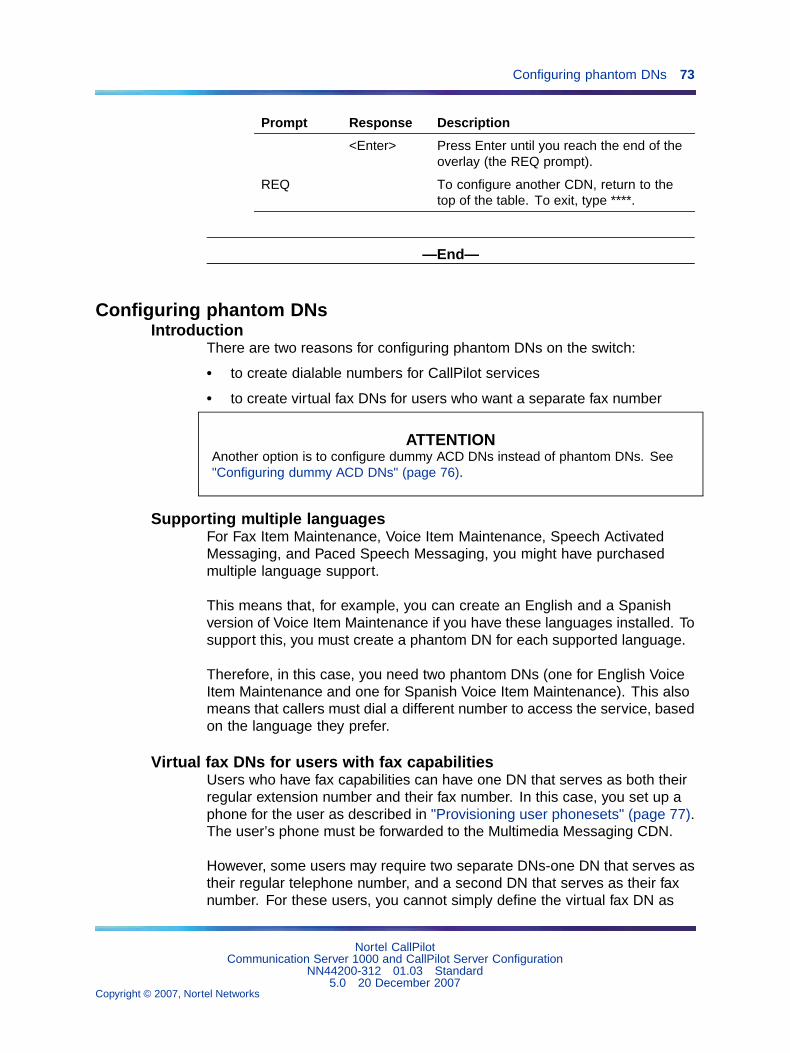
Configuring phantom DNs 73
Prompt Response Description
<Enter> Press Enter until you reach the end of theoverlay (the REQ prompt).
REQ To configure another CDN, return to thetop of the table. To exit, type ****.
—End—
Configuring phantom DNsIntroduction
There are two reasons for configuring phantom DNs on the switch:
• to create dialable numbers for CallPilot services
• to create virtual fax DNs for users who want a separate fax number
ATTENTIONAnother option is to configure dummy ACD DNs instead of phantom DNs. See"Configuring dummy ACD DNs" (page 76).
Supporting multiple languagesFor Fax Item Maintenance, Voice Item Maintenance, Speech ActivatedMessaging, and Paced Speech Messaging, you might have purchasedmultiple language support.
This means that, for example, you can create an English and a Spanishversion of Voice Item Maintenance if you have these languages installed. Tosupport this, you must create a phantom DN for each supported language.
Therefore, in this case, you need two phantom DNs (one for English VoiceItem Maintenance and one for Spanish Voice Item Maintenance). This alsomeans that callers must dial a different number to access the service, basedon the language they prefer.
Virtual fax DNs for users with fax capabilitiesUsers who have fax capabilities can have one DN that serves as both theirregular extension number and their fax number. In this case, you set up aphone for the user as described in "Provisioning user phonesets" (page 77).The user’s phone must be forwarded to the Multimedia Messaging CDN.
However, some users may require two separate DNs-one DN that serves astheir regular telephone number, and a second DN that serves as their faxnumber. For these users, you cannot simply define the virtual fax DN as
Nortel CallPilotCommunication Server 1000 and CallPilot Server Configuration
NN44200-312 01.03 Standard5.0 20 December 2007
Copyright © 2007, Nortel Networks
.
74 Chapter 4 Configuring the CS 1000 system
another DN on the user’s phoneset. Instead, you must set up a TN as thevirtual fax DN. Because physical TNs are more costly, Nortel recommendsthat you configure phantom DNs instead.
A separate TN is necessary because a single TN (the telephone) can becall forwarded to only one DN (regardless of how many DNs appear on thatphone). For these users, you must ensure that their telephone number(the mailbox DN) forwards to the Voice Messaging CDN, whereas their faxnumber (the virtual fax DN) forwards to the Multimedia Messaging CDN.
Note: When you add the user to CallPilot (as a mailbox owner), youmust define this virtual fax DN as one of the user’s extension DNs.
To check for existing phantom loopsA phantom loop must exist before you begin to configure phantom DNs.Use overlay 22 to print the configuration record to see if any phantomloops are already configured. A phantom loop is shown with the prefix "P",illustrated in this example:
Note: You can use superloops as phantom loops.
.CEQUMPED 8DSUPL 000 004 008 012016 032 036 040048 P064 P068 (phantom loops 64 and 68)DDCS..
If no phantom loops are configured, then continue with "To configure aphantom superloop" (page 74). If a phantom loop is configured, then go to"To configure a phantom DN" (page 75).
To configure a phantom superloop
Step Action
1 If no phantom loops are configured, load overlay 97.
2 For each prompt listed below, type the response indicated. Forthose prompts that are not listed, you can accept the default bypressing Enter.
Prompt Response Description
REQ CHG
TYPE SUPL Superloop
Nortel CallPilotCommunication Server 1000 and CallPilot Server Configuration
NN44200-312 01.03 Standard5.0 20 December 2007
Copyright © 2007, Nortel Networks
.
Configuring phantom DNs 75
Prompt Response Description
SUPL Nxxx Prefix the loop number with N to create aphantom loop.
The loop number range is 96-112 inmultiples of 4 (corresponds to slots 61- 80).
<Enter> Press Enter until you reach the end of theoverlay (the REQ prompt).
REQ **** Exits the overlay.
—End—
To configure a phantom DN
Step Action
1 Load overlay 10.
2 For each prompt listed below, type the response indicated. Forthose prompts that are not listed, you can accept the default bypressing Enter.
Prompt Response Description
REQ NEW
TYPE 500 PBX set type
TN c u Terminal number, where c is the card, andu is the unit. PHANTOM is echoed by theswitch when the specified loop is phantom.
CDEN xx The card density supported by the loop,where xx can be
DD - double density
4D - quadruple density
DN yyyy The DN must be single appearance.
CLS WTA UNR Unrestricted. Phantom DNs cannotoriginate calls, so this option is secure.
Nortel CallPilotCommunication Server 1000 and CallPilot Server Configuration
NN44200-312 01.03 Standard5.0 20 December 2007
Copyright © 2007, Nortel Networks
.

76 Chapter 4 Configuring the CS 1000 system
Prompt Response Description
FTR DCFW nnxxxx
DCFW = Default Call Forward
nn = maximum number of digits in theDCFW DN
xxxx = the CDN to which this DN forwards
If this phantom DN is for a voice service,type the Voice Messaging CDN.
If this phantom DN is for a fax service, typethe Multimedia Messaging CDN.
If this phantom DN is a virtual fax DN for auser, type the Multimedia Messaging CDN.
<Enter> Press Enter until you reach the end of theoverlay (REQ prompt).
REQ If you are finished adding phantom DNs,type **** to exit.
To add another DN, return to the top ofthe table.
—End—
Configuring dummy ACD DNsIntroduction
As an alternative to creating phantom DNs for directly dialable services, youcan create a dummy ACD DN that is set up to call forward to the appropriateCDN depending on the multimedia channel type required.
Example
• For a service that requires only voice capability, forward the dummy ACDDN to the Voice Messaging CDN.
• For a service that requires fax capability, forward the dummy ACD DN tothe Multimedia Messaging CDN.
Nortel CallPilotCommunication Server 1000 and CallPilot Server Configuration
NN44200-312 01.03 Standard5.0 20 December 2007
Copyright © 2007, Nortel Networks
.
Provisioning user phonesets 77
To configure dummy ACD DNs
Step Action
1 Load overlay 23.
2 For each prompt listed below, type the response indicated. Forthose prompts that are not listed, you can accept the default bypressing Enter.
Prompt Response Description
REQ NEW
TYPE ACD
CUST xx Customer number (0-99)
ACDN xxxx Enter the DN for the service.
MWC YES or NO Message Waiting Center. If the CallPilotserver is a Network Message Service(NMS) satellite site, set to YES. Otherwise,set to NO.
MAXP 1 This indicates that there are no agents inthis queue and it is, therefore, a dummyqueue.
NCFW yyyy Specify the appropriate CDN depending onmultimedia channel type required (VoiceMessaging CDN or Multimedia MessagingCDN).
<Enter> Press Enter until you reach the end of theoverlay (the REQ prompt).
REQ **** Exits the overlay.
—End—
Provisioning user phonesetsIntroduction
You must set up users’ phonesets in a certain way to support CallPilot. Theprocedure depends on whether you are provisioning a digital phoneset ora 500 phoneset.
Required featuresYou must set up phonesets to support the following features:
• Call forward no answer to the appropriate CDN (voice or multimedia)
Nortel CallPilotCommunication Server 1000 and CallPilot Server Configuration
NN44200-312 01.03 Standard5.0 20 December 2007
Copyright © 2007, Nortel Networks
.
78 Chapter 4 Configuring the CS 1000 system
Note: You cannot forward users’ phonesets to the Speech ActivatedMessaging CDN because this service does not provide callanswering functionality.
• Call forward busy to the appropriate CDN
• Call forward all calls to the appropriate CDN
• Message Waiting key with the appropriate CDN as the Message CenterDN
Note: If you do not plan to give fax capability to the user’s mailbox, usethe Voice Messaging CDN. If you plan to give fax capability to the user’smailbox, then use the Multimedia Messaging CDN.
To provision digital phonesets
Step Action
1 Load overlay 11.
2 For each prompt listed below, type the response indicated in overlay11. For those prompts that are not listed, you can accept the defaultby pressing Enter.
Prompt Response Description
REQ NEW orCHG
TYPE 2317, 2008,and so on
Type of set.
TN c u Terminal number of the phone, where c isthe card, and u is the unit.
CUST xx Customer number (0-99)
FDN yyyy Flexible call forward no answer DN. Setthis to the CDN of the Voice Messaging orMultimedia Messaging CDN queue.
HUNT zzzz Hunt (internal). Set this to the CDN of theVoice Messaging or Multimedia MessagingCDN queue.
CLS WTA, UNR,FNA, FBA,HTA, MWA
Call forward no answer allowed. Callforward busy allowed. Hunt allowed.Message waiting allowed.
KEY 0 SCR xxxx Single call ringing DN, where xxxx is theuser’s DN.
CPND New Calling Party Name Display (if adding anew set).
Nortel CallPilotCommunication Server 1000 and CallPilot Server Configuration
NN44200-312 01.03 Standard5.0 20 December 2007
Copyright © 2007, Nortel Networks
.
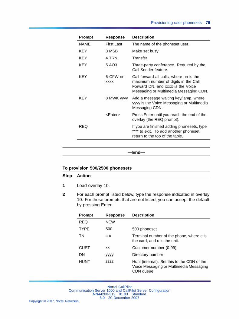
Provisioning user phonesets 79
Prompt Response Description
NAME First,Last The name of the phoneset user.
KEY 3 MSB Make set busy
KEY 4 TRN Transfer
KEY 5 AO3 Three-party conference. Required by theCall Sender feature.
KEY 6 CFW nnxxxx
Call forward all calls, where nn is themaximum number of digits in the CallForward DN, and xxxx is the VoiceMessaging or Multimedia Messaging CDN.
KEY 8 MWK yyyy Add a message waiting key/lamp, whereyyyy is the Voice Messaging or MultimediaMessaging CDN.
<Enter> Press Enter until you reach the end of theoverlay (the REQ prompt).
REQ If you are finished adding phonesets, type**** to exit. To add another phoneset,return to the top of the table.
—End—
To provision 500/2500 phonesets
Step Action
1 Load overlay 10.
2 For each prompt listed below, type the response indicated in overlay10. For those prompts that are not listed, you can accept the defaultby pressing Enter.
Prompt Response Description
REQ NEW
TYPE 500 500 phoneset
TN c u Terminal number of the phone, where c isthe card, and u is the unit.
CUST xx Customer number (0-99)
DN yyyy Directory number
HUNT zzzz Hunt (internal). Set this to the CDN of theVoice Messaging or Multimedia MessagingCDN queue.
Nortel CallPilotCommunication Server 1000 and CallPilot Server Configuration
NN44200-312 01.03 Standard5.0 20 December 2007
Copyright © 2007, Nortel Networks
.

80 Chapter 4 Configuring the CS 1000 system
Prompt Response Description
CLS WTA, UNR,HTA, MWA,FNA, FBA,XFA, LPA,DTN
Hunt allowed. Message waiting allowed.Call forward no answer allowed. Callforward busy allowed. MWI lamp isequipped (if not equipped, users arenotified of new messages by interrupteddial tone).
FTR FDN xxxx Flexible call forward no answer. Set thisto the Voice Messaging or MultimediaMessaging CDN.
FTR CFW yy Call forward all calls, where yy is themaximum DN length that users can specifyas the call forward DN.
<Enter> Press Enter until you reach the end of theoverlay (the REQ prompt).
REQ If you are finished adding phonesets, enter**** to exit. To add another phoneset,return to the top of the table.
—End—
Configuring the route data block for Network Message ServiceIntroduction
If you have purchased Network Message Service (NMS) to allow a numberof switches to share CallPilot (installed on only one switch), then configurethe route data block. This section provides instructions for this step.
For details on additional switch configuration for NMS, see the"Configuring the switches" chapter in the CallPilot Network Planning Guide(NN44200-201).
Note: Ensure that Digit Manipulation (DMI in overlay 86) is not usedto insert ESN access codes at the sending switch. ESN access codeinsertion must be done at the receiving switch (INAC in overlay 16).
To modify the route data block
Step Action
1 Load overlay 16.
2 For each prompt listed below, type the response indicated. Forthose prompts that are not listed, you can accept the default bypressing Enter.
Nortel CallPilotCommunication Server 1000 and CallPilot Server Configuration
NN44200-312 01.03 Standard5.0 20 December 2007
Copyright © 2007, Nortel Networks
.

Saving CS 1000 changes 81
Prompt Response Description
REQ NEW orCHG
TYPE RDB Route data block
CUST xx Customer number (0-99)
ROUTE Route number
PNI Customer Private Network ID of thenon-local target CS 1000 system
NCRD Yes Network call redirection provides the CLIDdisplay information.
TRO Yes Optimize trunk usage on this route.
INAC Yes Insert an ESN access code to incomingprivate network calls.
<Enter> Press Enter until you reach the end of theoverlay (REQ prompt).
REQ **** Exits the overlay.
—End—
Saving CS 1000 changesIntroduction
Once you modify the switch configuration to support CallPilot, save allchanges to disk.
To save the configuration
Step Action
1 Load overlay 43.
2 At the next "." prompt, type BKO to dump the data to disk.
Result: The system displays the data being saved. The followingmessage appears:
RECORD COUNT=xxxx
DATADUMP COMPLETE
3 Return to step 2, and repeat this step two more times.
Use a new disk each time.
Nortel CallPilotCommunication Server 1000 and CallPilot Server Configuration
NN44200-312 01.03 Standard5.0 20 December 2007
Copyright © 2007, Nortel Networks
.
82 Chapter 4 Configuring the CS 1000 system
ATTENTIONDo not remove the disk while the LED is lit. As long as the LED is on, thedisk is still being written to.
—End—
What is next?Continue with Chapter 5 "Configuring the CallPilot server software" (page83).
Nortel CallPilotCommunication Server 1000 and CallPilot Server Configuration
NN44200-312 01.03 Standard5.0 20 December 2007
Copyright © 2007, Nortel Networks
.
83
Chapter 5Configuring the CallPilot serversoftware
In this chapter"Overview" (page 83)
"Logging on to Windows 2003 on the CallPilot server" (page 84)
"Running the Setup Wizard" (page 85)
"Logging on to the CallPilot server with CallPilot Manager" (page 86)
"Running the Configuration Wizard" (page 91)
"Changing pcAnywhere caller passwords" (page 94)
"Setting Remote Desktop Policy on a Server" (page 95)
"Configuring CallPilot to operate in a Windows 2000 or 2003 domain" (page97)
OverviewIntroduction
The Configuration Wizard enables you to configure the CallPilot serversoftware. You can rerun the Configuration Wizard to update or review theserver configuration.
The Configuration Wizard is accessible from CallPilot Manager (aweb-based user interface). This chapter describes how to:
• log on to the operating system on the CallPilot server
• log on to the CallPilot server with CallPilot Manager run the ConfigurationWizard
Nortel CallPilotCommunication Server 1000 and CallPilot Server Configuration
NN44200-312 01.03 Standard5.0 20 December 2007
Copyright © 2007, Nortel Networks
.
84 Chapter 5 Configuring the CallPilot server software
• change the pcAnywhere caller passwords or set the Remote DesktopPolicy
• configure CallPilot to operate in a Windows 2000 or 2003 domain
CAUTIONRisk of improper configurationYou must use the Configuration Wizard to change the computername. If you use the operating system method to change thecomputer name, it is not properly updated in the CallPilot software.
Plan your responses to the Configuration WizardEnsure you have planned your responses to the Configuration Wizard bycompleting the "Configuration Wizard worksheet" in the CallPilot Installationand Configuration Task List.
Online Help for the Configuration WizardEach page in the Configuration Wizard contains a Help button and providesdetailed instructions regarding the selection or data entry required. ClickHelp at any time to get additional instructions.
Running the Configuration Wizard to detect replacement boardsWhen you replace MPB boards or MPC-8 cards, you must rerun theConfiguration Wizard to detect and initialize the hardware. You do not needto change any data in the Configuration Wizard to perform this operation,but you do need to apply the configuration changes as instructed on the lastpage of the Configuration Wizard.
Logging on to Windows 2003 on the CallPilot serverIntroduction
If you want to access CallPilot Manager from the web browser embedded onthe CallPilot server, you must first log on to Windows 2003 on the CallPilotserver. Alternatively, you can access CallPilot Manager from any PC thathas network access to the CallPilot server.
ATTENTIONWhen logging on, ensure that the CAPS key is not on. The password iscase-sensitive.
ATTENTIONWhen the system starts up, a mini-setup process launches which consists of anumber of restarts. When this process is completed, the Windows Logon screenappears
Nortel CallPilotCommunication Server 1000 and CallPilot Server Configuration
NN44200-312 01.03 Standard5.0 20 December 2007
Copyright © 2007, Nortel Networks
.
Running the Setup Wizard 85
To log on to Windows 2003 on the CallPilot server
Step Action
1 Ensure that the CallPilot server has started and the operatingsystem logon dialog box appears.
2 Type the user ID and password.
User ID Administrator You can choose to log onwith a different user ID thathas local administrativeprivileges.
Password (default) Bvw250 (or currentAdministratorpassword if it hasbeen changed)
Passwords for operatingsystem accounts should bechanged from default valuesto strong values known onlyto the customer. CallPilotsecurity is ultimately onlyas good as the passwordsused.
3 Click OK.
4 Continue with "Running the Setup Wizard" (page 85).
—End—
Running the Setup WizardAfter you type the user ID and password, the CallPilot Setup Wizardwelcome screen appears.
Note: For more information on the Setup Wizard, see the Upgrade andPlatform Migration Guide (NTP NN44200-400).
To run the Setup Wizard
Step Action
1 Read the information displayed on the screen and click Next.
Result: The Need SU/PEP Installation? screen appears.
2 If there are Service Updates (SUs) or PEPs available, you canchoose to install them now. Select Yes or No and click Next.
If you choose Yes, install SU/PEPs:
Result: The Installing SU/PEP screen appears.
Nortel CallPilotCommunication Server 1000 and CallPilot Server Configuration
NN44200-312 01.03 Standard5.0 20 December 2007
Copyright © 2007, Nortel Networks
.
86 Chapter 5 Configuring the CallPilot server software
a. Install all the required SUs and PEPs.
Note: Restart your computer (if required) after all SUs andPEPs are installed.
b. Click Next to continue if no restart is required. Otherwise, restartthe Wizard.
If you choose No, do not install SU/PEPs now.
Result: The Platform Validity Check screen appears.
3 View the items on the validity check and click Next.
4 When the system asks you if you have data to restore, select No.
5 Click Next to complete the Setup Wizard.
Result: The Finished screen appears.
6 Read the information displayed on the Finished screen and clickFinish.
7 Continue with "Logging on to the CallPilot server with CallPilotManager" (page 86).
—End—
Logging on to the CallPilot server with CallPilot ManagerIntroduction
The Configuration Wizard is a menu item in CallPilot Manager. CallPilotManager is the web-based CallPilot management tool, and can be accessedfrom any PC that has network access to the CallPilot server.
You can also access CallPilot Manager from the web browser on theCallPilot server. This may be the simplest method when installing CallPilotfor the first time.
Logon process overviewThe process for logging on to the CallPilot server with CallPilot Manageris the same for remote or local CallPilot servers. The logon process iscompleted in two stages:
Step Action
1 Launch the web browser (on the CallPilot server, or on any PC thathas network access to the CallPilot server), and then connect toCallPilot Manager.
Nortel CallPilotCommunication Server 1000 and CallPilot Server Configuration
NN44200-312 01.03 Standard5.0 20 December 2007
Copyright © 2007, Nortel Networks
.
Logging on to the CallPilot server with CallPilot Manager 87
For new installations, CallPilot Manager is located on the CallPilotserver. The URL syntax is http://CallPilot server host name or IPaddress/cpmgr/
Example: http://sunbird/cpmgr/, where sunbird is the host name.
If you installed CallPilot Manager on a stand-alone web server (aseparate PC that functions as a web server for CallPilot), the URLsyntax is http://web server host name or IP address/cpmgr/
Note: For more details, see "Relationship of the CallPilotManager web server to the CallPilot server" (page 87).
2 Log on to the CallPilot server with an administrator’s mailbox numberand password.
—End—
Relationship of the CallPilot Manager web server to the CallPilotserver
The CallPilot Manager web server software can be installed on theCallPilot server or on a stand-alone server. If the CallPilot Manager webserver software is installed on a stand-alone server, you must knowthe CallPilot Manager server’s host name or IP address, as well as theCallPilot server’s host name or IP address.
Nortel CallPilotCommunication Server 1000 and CallPilot Server Configuration
NN44200-312 01.03 Standard5.0 20 December 2007
Copyright © 2007, Nortel Networks
.
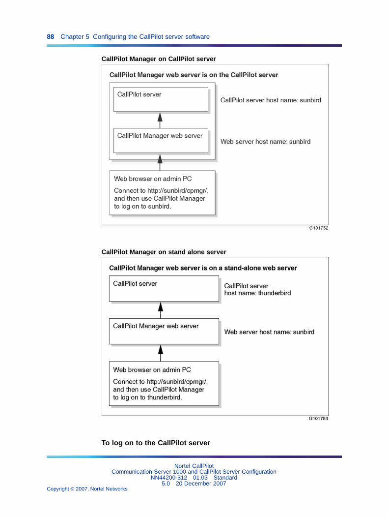
88 Chapter 5 Configuring the CallPilot server software
CallPilot Manager on CallPilot server
CallPilot Manager on stand alone server
To log on to the CallPilot server
Nortel CallPilotCommunication Server 1000 and CallPilot Server Configuration
NN44200-312 01.03 Standard5.0 20 December 2007
Copyright © 2007, Nortel Networks
.
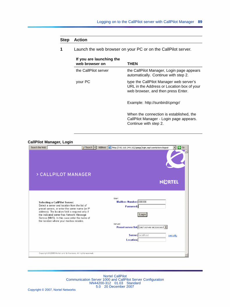
Logging on to the CallPilot server with CallPilot Manager 89
Step Action
1 Launch the web browser on your PC or on the CallPilot server.
If you are launching theweb browser on THEN
the CallPilot server the CallPilot Manager, Login page appearsautomatically. Continue with step 2.
your PC type the CallPilot Manager web server’sURL in the Address or Location box of yourweb browser, and then press Enter.
Example: http://sunbird/cpmgr/
When the connection is established, theCallPilot Manager - Login page appears.Continue with step 2.
CallPilot Manager, Login
Nortel CallPilotCommunication Server 1000 and CallPilot Server Configuration
NN44200-312 01.03 Standard5.0 20 December 2007
Copyright © 2007, Nortel Networks
.
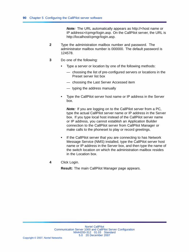
90 Chapter 5 Configuring the CallPilot server software
Note: The URL automatically appears as http://<host name orIP address>/cpmgr/login.asp. On the CallPilot server, the URL ishttp://localhost/cpmgr/login.asp.
2 Type the administration mailbox number and password. Theadministrator mailbox number is 000000. The default password is124578.
3 Do one of the following:
• Type a server or location by one of the following methods:
— choosing the list of pre-configured servers or locations in thePreset server list box
— choosing the Last Server Accessed item
— typing the address manually
• Type the CallPilot server host name or IP address in the Serverbox.
Note: If you are logging on to the CallPilot server from a PC,type the actual CallPilot server name or IP address in the Serverbox. If you type local host instead of the CallPilot server nameor IP address, you cannot establish an Application Builderconnection to the CallPilot server from CallPilot Manager ormake calls to the phoneset to play or record greetings.
• If the CallPilot server that you are connecting to has NetworkMessage Service (NMS) installed, type the CallPilot server hostname or IP address in the Server box, and then type the name ofthe switch location on which the administration mailbox residesin the Location box.
4 Click Login.
Result: The main CallPilot Manager page appears.
Nortel CallPilotCommunication Server 1000 and CallPilot Server Configuration
NN44200-312 01.03 Standard5.0 20 December 2007
Copyright © 2007, Nortel Networks
.

Running the Configuration Wizard 91
CallPilot Manager main screen
Note: Logging on for the first time forces you to change thepassword using numeric characters. (This is not a strongpassword, as described in the CallPilot Fundamentals Guide.)
5 Continue with "Running the Configuration Wizard" (page 91).
—End—
Running the Configuration WizardIntroduction
This section describes how to access and run the Configuration Wizard.
Requirements
• CallPilot language CD, if you are installing, adding, or upgradinglanguages
• completed "Configuration Wizard worksheet" from the CallPilotInstallation and Configuration Task List
• CallPilot keycode and dongle ID (serial number)
Nortel CallPilotCommunication Server 1000 and CallPilot Server Configuration
NN44200-312 01.03 Standard5.0 20 December 2007
Copyright © 2007, Nortel Networks
.
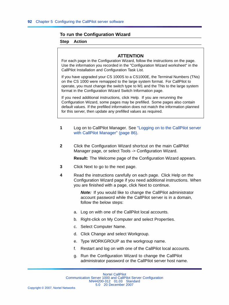
92 Chapter 5 Configuring the CallPilot server software
To run the Configuration Wizard
Step Action
ATTENTIONFor each page in the Configuration Wizard, follow the instructions on the page.Use the information you recorded in the "Configuration Wizard worksheet" in theCallPilot Installation and Configuration Task List.
If you have upgraded your CS 1000S to a CS1000E, the Terminal Numbers (TNs)on the CS 1000 were remapped to the large system format. For CallPilot tooperate, you must change the switch type to M1 and the TNs to the large systemformat in the Configuration Wizard Switch Information page.
If you need additional instructions, click Help. If you are rerunning theConfiguration Wizard, some pages may be prefilled. Some pages also containdefault values. If the prefilled information does not match the information plannedfor this server, then update any prefilled values as required.
1 Log on to CallPilot Manager. See "Logging on to the CallPilot serverwith CallPilot Manager" (page 86).
2 Click the Configuration Wizard shortcut on the main CallPilotManager page, or select Tools -> Configuration Wizard.
Result: The Welcome page of the Configuration Wizard appears.
3 Click Next to go to the next page.
4 Read the instructions carefully on each page. Click Help on theConfiguration Wizard page if you need additional instructions. Whenyou are finished with a page, click Next to continue.
Note: If you would like to change the CallPilot administratoraccount password while the CallPilot server is in a domain,follow the below steps:
a. Log on with one of the CallPilot local accounts.
b. Right-click on My Computer and select Properties.
c. Select Computer Name.
d. Click Change and select Workgroup.
e. Type WORKGROUP as the workgroup name.
f. Restart and log on with one of the CallPilot local accounts.
g. Run the Configuration Wizard to change the CallPilotadministrator password or the CallPilot server host name.
Nortel CallPilotCommunication Server 1000 and CallPilot Server Configuration
NN44200-312 01.03 Standard5.0 20 December 2007
Copyright © 2007, Nortel Networks
.
Running the Configuration Wizard 93
5 When you reach the end of the Configuration Wizard, click Finish tosave the Configuration Wizard changes, or click Cancel to discardany changes. No changes are implemented unless you click Finish.
Result: The Configuration Wizard requires up to an hour to applychanges, depending on the number of languages you are installingor updating, and the size of the system. When CallPilot completesthe configuration changes, you are prompted to restart the server.
6 Restart the server.
Note: Ensure you use the restart procedure documented in theCallPilot Installation and Configuration Task List.
Result: The server restarts and the configuration changes are ineffect.
—End—
Note: If you run the Configuration Wizard after your CallPilot serveris added to a domain, two procedures do not work until you removethe server from the domain. The two procedures are: changing thecomputer name, and changing the local administrator account. For moreinformation, see "Configuring CallPilot to operate in a Windows 2000 or2003 domain" (page 97).
Considerations on configuring STI links for the CallPilot tower andrackmount servers
The Configuration Wizard application is used to configure the switchtelephony interface (STI) links and the DS0 channels between the MGatecards in the CS 1000 switch and the MPB16-4 or MPB96 boards in theCallPilot server. Each MPB16-4 board can have two STI links and each STIlink can have a maximum of 32 DS0 channels. Each MPB96 board canhave three STI links. See the Configuration Wizard online Help for moreinformation on configuring the STI links and the DS0 channels.
If your CallPilot server contains two MPB16-4 boards connected to twoMGate cards and you need more than 32 DS0 channels between theCallPilot server and the switch, then you must configure both STI links onMPB16-4 #1 before starting to configure the STI links on MPB16-4 #2.
Make sure that you are always able to identify the MPB16-4 boards. See"Identifying the location of MPB 1 and MPB 2" (page 43) for the numbersof the slots in which the MPB #1 and MPB #2 can be installed on CallPilotservers.
Nortel CallPilotCommunication Server 1000 and CallPilot Server Configuration
NN44200-312 01.03 Standard5.0 20 December 2007
Copyright © 2007, Nortel Networks
.
94 Chapter 5 Configuring the CallPilot server software
If you configure an STI link on MPB16-4 #2 before configuring both STI linkson MPB16-4 #1, the DS0 channels on MPB16-4 #2 are not functional. As aresult, you experience no voice in the slot that holds the MPB16-4 #2 board.
What is next?Your next step will depend on your choice of a remote support tool.
• If you are using pcAnywhere, continue to "Changing pcAnywhere callerpasswords" (page 94).
Note: pcAnywhere is not supported on the CallPilot 201i system.Continue to "Setting Remote Desktop Policy on a Server" (page 95).
• If you are using Remote Desktop Connection, continue to "SettingRemote Desktop Policy on a Server" (page 95).
Changing pcAnywhere caller passwordsIntroduction
With pcAnywhere, you can perform advanced administrative tasks on theserver from a remote PC. You can control the server as though you weredirectly connected to the server.
pcAnywhere is installed and configured on the server at the factory. Onelicensed copy of pcAnywhere is provided for the server on the CallPilotApplication CD-ROM.
To install pcAnywhere on another PC, you must purchase a separatelicense. For instructions on how to install and configure pcAnywhere onanother PC, see the CallPilot Administrator’s Guide (NN44200-601).
To change pcAnywhere caller passwords
Step Action
1 Stop the pcAnywhere session, if one is running.
2 Click Start -> Programs -> Symantec pcAnywhere.
Result: The Symantec pcAnywhere window opens.
3 Click the Hosts icon in the pcAnywhere section of the SymantecpcAnywhere window.
Result: The list of hosts is displayed.
4 Right-click the CallPilot Support icon, and then choose Propertiesfrom the pop-up menu.
Result: The Host Properties: CallPilot Support dialog box appears.
5 Click the Callers tab.
Nortel CallPilotCommunication Server 1000 and CallPilot Server Configuration
NN44200-312 01.03 Standard5.0 20 December 2007
Copyright © 2007, Nortel Networks
.
Setting Remote Desktop Policy on a Server 95
6 Right-click the CallPilotDist icon, and then choose Properties fromthe pop-up menu.
7 In the Password box, type a new CallPilotDist password.
8 In the Confirm Password box, type the CallPilotDist password again.
9 Click Apply.
10 Click OK.
11 Click OK to return to the main Symantec pcAnywhere window.
12 Double-click the CallPilot icon to restart the pcAnywhere session.
—End—
What is Next?Continue to "Configuring CallPilot to operate in a Windows 2000 or 2003domain" (page 97).
Setting Remote Desktop Policy on a ServerCallPilot server comes with the Remote Desktop server enabled andconfigured for use by default. If necessary, remote desktop access canbe enabled or disabled as follows:
To set remote desktop policy
Step Action
1 From the CallPilot server desktop, right-click My Computer, thenchoose Properties, and click on the Remote tab.
Result: The System Properties screen appears.
Nortel CallPilotCommunication Server 1000 and CallPilot Server Configuration
NN44200-312 01.03 Standard5.0 20 December 2007
Copyright © 2007, Nortel Networks
.
96 Chapter 5 Configuring the CallPilot server software
2 Ensure the Allow users to connect remotely to this computer optionis selected. Click OK to close the window.
3 Open the Group Policy Snap-in to choose from the five optionsavailable for remote control settings. Open a command promptwindow by clicking Start > Run.
Result: The Open window appears.
4 Type gpedit.msc and click OK or press Enter.
Result: The Group Policy Object Editor window appears.
5 On the left side of the window, expand Computer Configuration,Administrative Templates, Windows Components, and then selectTerminal Services.
6 On the right side of the window, double-click Sets Rules for RemoteControl Terminal Services User Sessions.
Nortel CallPilotCommunication Server 1000 and CallPilot Server Configuration
NN44200-312 01.03 Standard5.0 20 December 2007
Copyright © 2007, Nortel Networks
.
Configuring CallPilot to operate in a Windows 2000 or 2003 domain 97
7 The Sets Rules for Remote Control Terminal Services User Sessionswindow appears.
8 Select Enabled to load options into the box.
9 The default and recommended setting for CallPilot is Enabled withFull Control without User’s Permission selected. This setting allowsfor RDC sessions without requiring interaction or consent from alocal console user.
Adjust the settings as required, and click OK to close the screen.
10 Click File > Close to close the Group Policy Object Editor.
Note: For instructions on installing and configuring RemoteDesktop Connection (RDC), see the CallPilot TroubleshootingReference Guide (NN44200-700).
—End—
What is Next?Continue to "Configuring CallPilot to operate in a Windows 2000 or 2003domain" (page 97).
Configuring CallPilot to operate in a Windows 2000 or 2003 domainIntroduction
Nortel supports CallPilot as a member in a Windows 2000 or 2003 domain.Customers can add their server machine to a Windows 2000 or 2003domain for added security and manageability. Whether you are upgradingto CallPilot 4.0 or installing a new CallPilot 4.0 system, you can move yourserver from a Windows workgroup to a Windows 2000 or 2003 domain.
Note: You do not need to add CallPilot to a domain. This procedure isoptional. Nortel will continue to support CallPilot 4.0 in a workgroup. Ifyou do not want to add your server to a domain, continue with Chapter 6"Testing the CallPilot installation" (page 109).
To add your CallPilot server to a domain, you require network administratorprivileges. To perform this procedure, you can either work with your networkadministrator, or ask your network administrator to create a user accountwith network administrator privileges.
When you add your CallPilot server to a domain, Nortel recommends thatyou see the latest Distributor Technical Reference (DTR), available on thePIC web site (www.nortel.com/pic).
This section describes how to:
• set domain group policy
Nortel CallPilotCommunication Server 1000 and CallPilot Server Configuration
NN44200-312 01.03 Standard5.0 20 December 2007
Copyright © 2007, Nortel Networks
.
98 Chapter 5 Configuring the CallPilot server software
• add your CallPilot server to the domain
• stop and disable Win32 Time Service on the CallPilot server
• set up user accounts for remote access
• run Configuration Wizard in a domain
To set domain group policyWhen you install Release 4.0 of CallPilot, the installation creates localaccounts that contain default strong passwords of six characters. Asa result, your local domain group policy can conflict with these defaultsettings. The CallPilot administrator account can be affected. See "Runningthe Configuration Wizard" (page 91) for information on how to change theuser account.
If you identify conflicts, you can adjust your group policies for CallPilot, oryou can exclude the CallPilot server machine from a specific group policy.
When you add your CallPilot server to a domain, you must also considerthat the Windows 2003 Domain Controller determines the security policythat applies to the server.
Note: Nortel strongly recommends that you add the server to a domainafter running the Configuration Wizard.
To add CallPilot server to a domainAfter you install and configure your CallPilot server, and you confirm thatyour network administrator has set up a Domain Controller and a DNSserver on the network, you can add your server as a member of an existingdomain.
To add the server as a member of an existing domain:
Step Action
1 On the CallPilot server, courtesy stop all CallPilot channels. See theInstallation and Configuration Task List Guide (NN44200-306), formore information.
2 Compare the M1/Succession time to the time on the DomainController, or the time on any existing Domain member computer.
Note 1: Nortel recommends that the difference between theM1/Succession time and the Domain Controller time does notexceed 10 seconds.
Note 2: The CallPilot server time is updated by theM1/Succession time, so when you change the M1/Successiontime, the CallPilot server time is also updated.
Nortel CallPilotCommunication Server 1000 and CallPilot Server Configuration
NN44200-312 01.03 Standard5.0 20 December 2007
Copyright © 2007, Nortel Networks
.
Configuring CallPilot to operate in a Windows 2000 or 2003 domain 99
a. If the difference in the M1/Succession time and the DomainController time is greater than 10 seconds, go to Step 3 to changethe M1/Succession time to match the Domain Controller time.
b. If the difference in the M1/Succession time and the DomainController time is less than 10 seconds, go to Step 4. You do notneed to adjust the time.
3 To change M1/Succession time to match the Domain controller time,perform the following steps:
a. Log on to the M1/Succession server and go to LD 2.
b. Type TTAD and press Return.
Result: The current M1/Succession format for the time and thetime appear. An example is:
<day> <month> <year> <hour> <minute> <sec> 12 01 200522 35 00
c. Type STAD and press Return.
Result: The time and date appear. An example is:
<day> <month> <year> <hour> <minute> <sec> 12 01 200522 35 00
d. Change the time to match the Domain Controller time.
Note 1: Nortel recommends that you keep the time differencebetween the M1 and the Domain Controller time to within a fewseconds (+/- 10 seconds). The maximum difference can be upto five minutes before Kerberos authentication problems canarise. Once a month, check the times on the M1/Successionand the domain to ensure that the five minute tolerance is notexceeded. If the time difference is exceeded by five minutes,you can experience problems with Event Viewer, audit logs, andlocal system network shares. You can also receive messageson the local server that indicate that the CallPilot server time isout of synchronization with the Domain Controller. Day-to-dayoperation of the CallPilot server, however, should not be affected.
Note 2: For normal CallPilot operation, support, andmaintenance, you must create a domain user account. In orderfor you to receive administrator privileges on the local server, theCallPilot administrator must add the domain user account to theCallPilot local administrator group.
4 Exit the pcAnywhere session if it is running.
5 On the CallPilot server Windows desktop, right-click on MyComputer, and then select Properties.
Nortel CallPilotCommunication Server 1000 and CallPilot Server Configuration
NN44200-312 01.03 Standard5.0 20 December 2007
Copyright © 2007, Nortel Networks
.

100 Chapter 5 Configuring the CallPilot server software
6 In the System Properties window, click the Computer Name tab.
Result: The following System Properties window appears.
7 Click Change.
Result: The Computer Name Changes window appears.
Nortel CallPilotCommunication Server 1000 and CallPilot Server Configuration
NN44200-312 01.03 Standard5.0 20 December 2007
Copyright © 2007, Nortel Networks
.

Configuring CallPilot to operate in a Windows 2000 or 2003 domain 101
8 To add the server to an existing domain, click the Domain optionbutton in the Member of pane, and then type the name of thedomain.
9 Click OK.
Result: The Domain Username And Password window appears.
10 Type the username and password from the user account on theDomain Controller that has remote access privileges.
Note: You need a domain administrator username andpassword.
11 Click OK.
Result: When the system processes your change successfully,the following dialog box appears, notifying you that the server nowbelongs to the specified domain.
12 Click OK.
13 Click Yes to restart your computer.
—End—
To stop and disable the Win32 Time Service
Note: If you are on a T1/SMDI switch, this procedure does not apply toa T1/SMDI system.
To prevent the Domain Controller from controlling the CallPilot server time,you must disable the Win32 time Service on the CallPilot server. This allowsthe M1 or Succession switch to continue to control the CallPilot server time.
Nortel CallPilotCommunication Server 1000 and CallPilot Server Configuration
NN44200-312 01.03 Standard5.0 20 December 2007
Copyright © 2007, Nortel Networks
.

102 Chapter 5 Configuring the CallPilot server software
To stop and disable the Win 32 Time Service
Step Action
1 Log on to the CallPilot server.
2 Right-click on My Computer and select Manage > Services andApplications > Services.
Result: The Computer Management window appears:
a. In the right pane, right-click on Windows Time and select Stop.
b. When the Service stops, right-click on Windows Time andselect Properties > General tab.
Result: The Windows Time Properties (Local Computer) windowappears:
Nortel CallPilotCommunication Server 1000 and CallPilot Server Configuration
NN44200-312 01.03 Standard5.0 20 December 2007
Copyright © 2007, Nortel Networks
.

Configuring CallPilot to operate in a Windows 2000 or 2003 domain 103
c. Select Disabled from the Startup type menu.
d. Click Apply, and then click OK.
e. On the Computer Management window, verify that the WindowsTime service is disabled.
f. Close the Computer Management window.
—End—
To set up user accounts for remote access domainIn a Windows Server 2003 domain environment, you must create a dial-upuser as a Domain user on the Domain Controller and assign dial-in accesspermissions to this user. When dialing in to the RAS configuration CallPilotRelease 4.0 server, the Domain controller authenticates the username andpassword.
Note: Local dial-in access is no longer available for the administratoraccount through Routing and Remote Access server (RRAS). You canobtain remote dial-in access to the CallPilot system by setting up adomain account with dial-in permissions.
After you set up a domain user account and assign dial-in accesspermission, you have two options to log on to the local CallPilot systemusing dial-in access permission.
See below an example of a Domain user account with dial-in access:
Nortel CallPilotCommunication Server 1000 and CallPilot Server Configuration
NN44200-312 01.03 Standard5.0 20 December 2007
Copyright © 2007, Nortel Networks
.
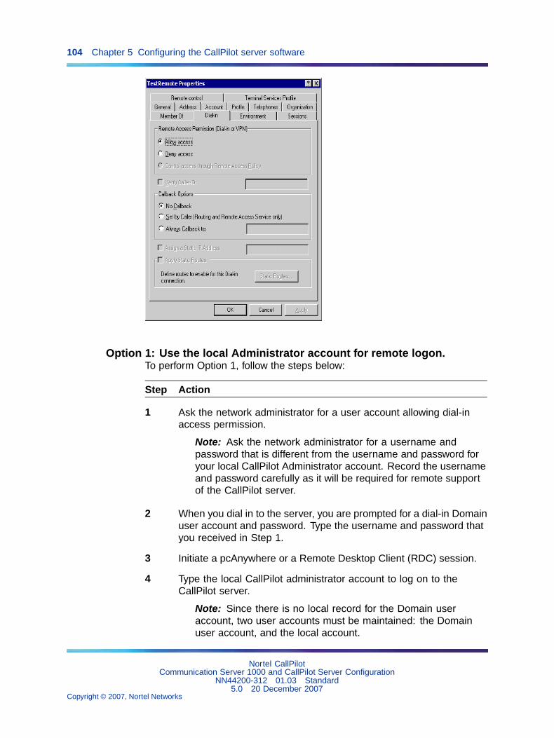
104 Chapter 5 Configuring the CallPilot server software
Option 1: Use the local Administrator account for remote logon.To perform Option 1, follow the steps below:
Step Action
1 Ask the network administrator for a user account allowing dial-inaccess permission.
Note: Ask the network administrator for a username andpassword that is different from the username and password foryour local CallPilot Administrator account. Record the usernameand password carefully as it will be required for remote supportof the CallPilot server.
2 When you dial in to the server, you are prompted for a dial-in Domainuser account and password. Type the username and password thatyou received in Step 1.
3 Initiate a pcAnywhere or a Remote Desktop Client (RDC) session.
4 Type the local CallPilot administrator account to log on to theCallPilot server.
Note: Since there is no local record for the Domain useraccount, two user accounts must be maintained: the Domainuser account, and the local account.
Nortel CallPilotCommunication Server 1000 and CallPilot Server Configuration
NN44200-312 01.03 Standard5.0 20 December 2007
Copyright © 2007, Nortel Networks
.

Configuring CallPilot to operate in a Windows 2000 or 2003 domain 105
—End—
Option 2: Use the Domain user account for remote logonTo perform Option 2, follow the steps below:
Step Action
1 Ask the network administrator for a user account allowing dial-inaccess permission.
Note: Ask the network administrator for a username andpassword that is different from the username and password foryour local CallPilot Administrator account. Record the usernameand password carefully as it will be required for remote supportof the CallPilot server. The dial-in account must be added tothe CallPilot local Administrator group to grant administratorprivileges to support personnel.
2 Initiate a pcAnywhere or a RDC session.
3 When you dial in to the server, the system prompts you for a dial-indomain user account and password. Type the username andpassword that you received in Step 1.
Note: This option manages the user account in one location, forboth dial-in access through pcAnywhere or RDC.
—End—
To run Configuration Wizard in a domainAfter you add the CallPilot server to a domain, the domain account that isused to log on to the CallPilot server does not have network administratorprivileges. As a result, if you run the Configuration Wizard after you addyour CallPilot server to the domain, two procedures do not work until youremove the server from the domain. The two procedures are: changing thecomputer name, and changing the local administrator account. To performthese two procedures when your server is in a domain, you must removethe server from the domain, perform the procedure, and then add the serverto the domain again.
To change the computer nameTo change the computer name when you run Configuration Wizard andCallPilot is a member of a domain, perform the following steps:
Nortel CallPilotCommunication Server 1000 and CallPilot Server Configuration
NN44200-312 01.03 Standard5.0 20 December 2007
Copyright © 2007, Nortel Networks
.

106 Chapter 5 Configuring the CallPilot server software
Step Action
1 Ask your network administrator to remove the CallPilot server fromthe domain and add the server to a workgroup. You can also performthis step on your own, if you acquire network administrator privilegesfrom your network administrator.
2 Shut down and restart the CallPilot system.
3 Run the Configuration Wizard and select the option to change thecomputer name.
4 Shutdown and restart the CallPilot system.
5 Ask your network administrator to add the CallPilot server to thedomain. You can also perform this step on your own, if you acquirenetwork administrator privileges from your network administrator.
6 Shutdown and restart the CallPilot system.
—End—
To change the local account passwordsTo change the local account passwords when you run Configuration Wizardand CallPilot is a member of a domain, perform the following steps:
Step Action
1 Ask your network administrator to remove the CallPilot server fromthe domain and add the server to a workgroup. You can also performthis step on your own, if you acquire network administrator privilegesfrom your network administrator.
2 Shut down and restart the CallPilot system.
3 Run the Configuration Wizard and select the option to change theaccount passwords.
4 Shutdown and restart the CallPilot system.
5 Ask your network administrator to add the CallPilot server to thedomain. You can also perform this step on your own, if you acquirenetwork administrator privileges from your network administrator.
6 Shutdown and restart the CallPilot system.
Nortel CallPilotCommunication Server 1000 and CallPilot Server Configuration
NN44200-312 01.03 Standard5.0 20 December 2007
Copyright © 2007, Nortel Networks
.

What is next? 107
—End—
What is next?Continue with Chapter 6 "Testing the CallPilot installation" (page 109).
Nortel CallPilotCommunication Server 1000 and CallPilot Server Configuration
NN44200-312 01.03 Standard5.0 20 December 2007
Copyright © 2007, Nortel Networks
.

108 Chapter 5 Configuring the CallPilot server software
Nortel CallPilotCommunication Server 1000 and CallPilot Server Configuration
NN44200-312 01.03 Standard5.0 20 December 2007
Copyright © 2007, Nortel Networks
.
109
Chapter 6Testing the CallPilot installation
In this chapter"Checking that CallPilot is ready to accept calls" (page 109)
"Testing the connection to the ELAN subnet" (page 113)
"Testing the connection to the NNS Subnet" (page 114)
"Verifying that CallPilot can receive calls" (page 114)
"Testing the CallPilot software and channels" (page 115)
Checking that CallPilot is ready to accept calls
ATTENTIONCallPilot is not ready to accept calls until the CallPilot services are fullyoperational. CallPilot services require approximately 10 minutes after starting upthe CallPilot server to become fully operational.
IntroductionCallPilot uses various system-ready indicators to indicate when it is ready toaccept calls, including:
• displaying messages in dialog boxes on the CallPilot server monitorafter logon It also displays a status icon in the top right corner of theCallPilot Manager window.
• generating events that can be viewed in the Event Browser or AlarmMonitor in CallPilot Manager
• displaying status using the hex display (applies only to the 201i server)
Nortel CallPilotCommunication Server 1000 and CallPilot Server Configuration
NN44200-312 01.03 Standard5.0 20 December 2007
Copyright © 2007, Nortel Networks
.
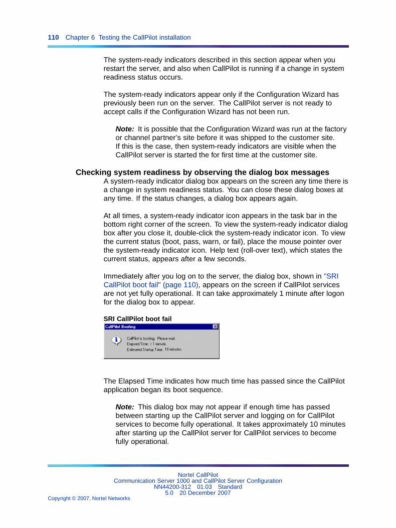
110 Chapter 6 Testing the CallPilot installation
The system-ready indicators described in this section appear when yourestart the server, and also when CallPilot is running if a change in systemreadiness status occurs.
The system-ready indicators appear only if the Configuration Wizard haspreviously been run on the server. The CallPilot server is not ready toaccept calls if the Configuration Wizard has not been run.
Note: It is possible that the Configuration Wizard was run at the factoryor channel partner’s site before it was shipped to the customer site.If this is the case, then system-ready indicators are visible when theCallPilot server is started the for first time at the customer site.
Checking system readiness by observing the dialog box messagesA system-ready indicator dialog box appears on the screen any time there isa change in system readiness status. You can close these dialog boxes atany time. If the status changes, a dialog box appears again.
At all times, a system-ready indicator icon appears in the task bar in thebottom right corner of the screen. To view the system-ready indicator dialogbox after you close it, double-click the system-ready indicator icon. To viewthe current status (boot, pass, warn, or fail), place the mouse pointer overthe system-ready indicator icon. Help text (roll-over text), which states thecurrent status, appears after a few seconds.
Immediately after you log on to the server, the dialog box, shown in "SRICallPilot boot fail" (page 110), appears on the screen if CallPilot servicesare not yet fully operational. It can take approximately 1 minute after logonfor the dialog box to appear.
SRI CallPilot boot fail
The Elapsed Time indicates how much time has passed since the CallPilotapplication began its boot sequence.
Note: This dialog box may not appear if enough time has passedbetween starting up the CallPilot server and logging on for CallPilotservices to become fully operational. It takes approximately 10 minutesafter starting up the CallPilot server for CallPilot services to becomefully operational.
Nortel CallPilotCommunication Server 1000 and CallPilot Server Configuration
NN44200-312 01.03 Standard5.0 20 December 2007
Copyright © 2007, Nortel Networks
.
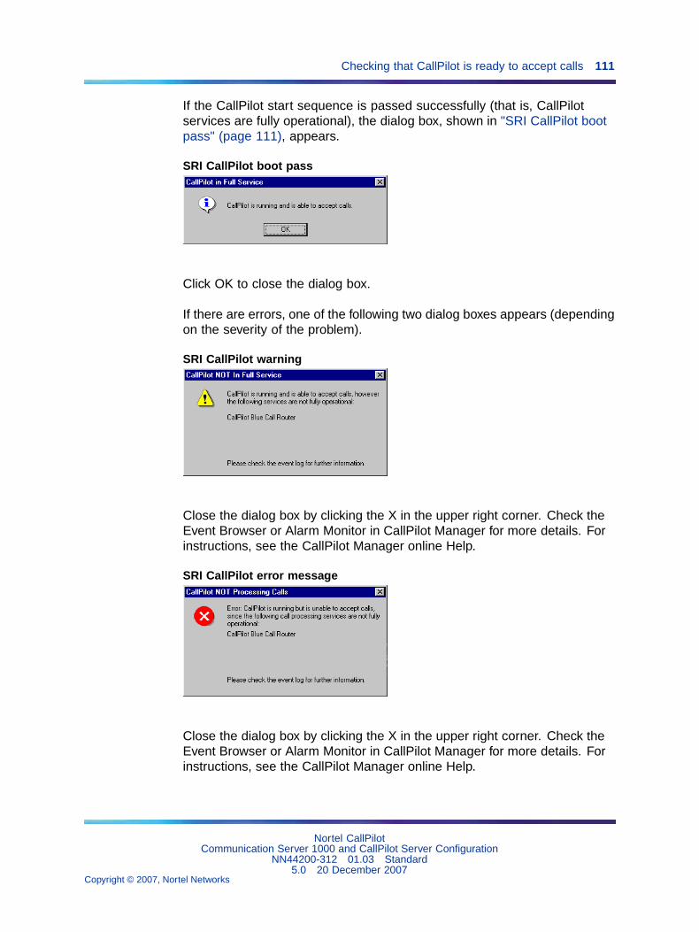
Checking that CallPilot is ready to accept calls 111
If the CallPilot start sequence is passed successfully (that is, CallPilotservices are fully operational), the dialog box, shown in "SRI CallPilot bootpass" (page 111), appears.
SRI CallPilot boot pass
Click OK to close the dialog box.
If there are errors, one of the following two dialog boxes appears (dependingon the severity of the problem).
SRI CallPilot warning
Close the dialog box by clicking the X in the upper right corner. Check theEvent Browser or Alarm Monitor in CallPilot Manager for more details. Forinstructions, see the CallPilot Manager online Help.
SRI CallPilot error message
Close the dialog box by clicking the X in the upper right corner. Check theEvent Browser or Alarm Monitor in CallPilot Manager for more details. Forinstructions, see the CallPilot Manager online Help.
Nortel CallPilotCommunication Server 1000 and CallPilot Server Configuration
NN44200-312 01.03 Standard5.0 20 December 2007
Copyright © 2007, Nortel Networks
.

112 Chapter 6 Testing the CallPilot installation
Alternative methods for verifying that CallPilot is ready to accept callsView events in CallPilot Manager or in the operating systemEvent Viewer on the serverThe Pass, Warning, and Error system-ready indicator messages appear asevents in the Event Browser and Alarm Monitor in CallPilot Manager, and inthe operating system Event Viewer on the server.
By default
• the Event Browser and Alarm Monitor show only the latest 100 events
Change the default settings to remove the system-ready indicator eventsfrom the Event Browser and Alarm Monitor windows.
• the Event Browser lists only Critical events
You can change the Filter Criteria so that Major, Minor, and Informationevents are listed as well.
For detailed instructions on viewing events, see the CallPilot Manageronline Help.
Observe the HEX display (for the 201i server only)The HEX display on the 201i server faceplate displays the followingmessages.
Note: The DOWN, OK, MIN, MAJ, CRI, and "???" messages canappear regardless of whether the Configuration Wizard has been run.Some MIN, MAJ, and CRI events may appear because the server hasnot been configured. These events may be resolved after running theConfiguration Wizard. The BOOT, PASS, WARN, and FAIL messagesare system-ready indicator messages; they do not appear if theConfiguration Wizard has not been run.
IPE CallPilot serverHEX display Description
DOWN The operating system is starting.
OK The operating system start sequence has passed.
BOOT CallPilot is starting and is not yet fully operational.Please wait.
PASS CallPilot is fully operational and ready to accept calls.
WARN CallPilot is ready to accept calls; however, someservices failed the start sequence. Check the event logfor further information.
FAIL CallPilot failed the start sequence and cannot acceptcalls. Check the event log for further information.
Nortel CallPilotCommunication Server 1000 and CallPilot Server Configuration
NN44200-312 01.03 Standard5.0 20 December 2007
Copyright © 2007, Nortel Networks
.
Testing the connection to the ELAN subnet 113
IPE CallPilot serverHEX display Description
MIN A minor alarm has occurred. Check the event log forfurther information.
MAJ A major alarm has occurred. Check the event log forfurther information.
CRI A critical alarm has occurred. Check the event log forfurther information.
??? An alarm of unknown severity has occurred. This errorshould not occur on a properly installed system. Theseverity of this event is treated as higher-than-critical.
Testing the connection to the ELAN subnetIntroduction
This procedure tests the network connection between the server and theCS 1000 system over the ELAN subnet.
ATTENTIONDisconnect the Nortel Server Subnet (NS Subnet) from the ELAN subnet beforetesting to ensure that the ping is testing only the ELAN subnet.
To test the connection to the ELAN subnet
Step Action
1 Click Start -> Programs -> Accessories -> Command Prompt.
Result: The Command Prompt window appears.
2 Type ping followed by the ELAN subnet IP address for the CS 1000system, and then press Enter.
Note: This is the ELAN subnet IP address specified for the CS1000 system in. See the Configuration Wizard worksheets thatyou completed in the CallPilot Installation and Configuration TaskList for the IP address.
Example: ping 255.255.255.255
Result: The display should indicate a successful ping. If the pingis not successful, check the connection from the CallPilot server’sELAN subnet card to the CS 1000 system.
3 If the CallPilot server is also connected to a Nortel Server Subnet(NS Subnet), then continue with "Testing the connection to the NNSSubnet" on page 160.
Nortel CallPilotCommunication Server 1000 and CallPilot Server Configuration
NN44200-312 01.03 Standard5.0 20 December 2007
Copyright © 2007, Nortel Networks
.
114 Chapter 6 Testing the CallPilot installation
If the CallPilot server is not connected to a Nortel Server Subnet(NS Subnet), then type exit and press Enter to close the CommandPrompt window. Then continue with "Verifying that CallPilot canreceive calls" (page 114).
—End—
Testing the connection to the NNS SubnetIntroduction
This procedure tests the network connection between the server and theNortel Server Subnet (NS Subnet). This applies only if CallPilot has an NNSSubnet card and is connected to an NNS Subnet.
ATTENTIONDisconnect the NNS Subnet from the ELAN subnet before testing to ensure thatthe ping is testing only the NNS Subnet.
To test the connection to the NNS Subnet
Step Action
1 Click Start -> Programs -> Accessories -> Command Prompt.
Result: The Command Prompt window appears.
2 Type ping followed by the NNS Subnet IP address of another PC onthe NNS Subnet, and then press Enter.
Example: ping 255.255.255.255
Result: The display indicates a successful ping.
3 Type exit, and then press Enter to close the Command Promptwindow.
—End—
Verifying that CallPilot can receive callsIntroduction
The following procedure is a basic test to verify that CallPilot is able toreceive calls from the CS 1000 system and answer those calls. A morethorough test that requires the use of CallPilot Manager is described in"Testing the CallPilot software and channels" (page 115).
Nortel CallPilotCommunication Server 1000 and CallPilot Server Configuration
NN44200-312 01.03 Standard5.0 20 December 2007
Copyright © 2007, Nortel Networks
.

Testing the CallPilot software and channels 115
To verify that CallPilot can receive calls
Step Action
1 Ensure that CallPilot services are fully operational before you begin.
For instructions, see "Checking that CallPilot is ready to acceptcalls" (page 109).
2 Dial the main Voice Messaging DN that you defined in theConfiguration Wizard.
3 Listen for a response from CallPilot (for example, "CallPilot fromNortel ..."), and then hang up.
If you do not get a response, then do the following:
a. Check the cabling between the server and the CS 1000 system.
b. Verify that the CS 1000 system is processing calls to otherextensions.
c. see the CallPilot Server Maintenance and Diagnostics guidefor your server.
—End—
What is next?Continue with "Testing the CallPilot software and channels" (page 115).
Testing the CallPilot software and channelsIntroduction
This section provides a series of tests of the CallPilot installation, includingverifying that
• you can leave a message
• you can retrieve a message
• each call channel and multimedia (DSP) channel is functioning properly
Before you begin
• Ensure that you have configured the CS 1000 system and CallPilotserver, as described in this guide.
• Obtain the ACD DN for CallPilot.
• Identify a phoneset DN that exists on the CS 1000 system that you canuse for testing.
• Have a pencil and paper ready to record the results of the tests.
Nortel CallPilotCommunication Server 1000 and CallPilot Server Configuration
NN44200-312 01.03 Standard5.0 20 December 2007
Copyright © 2007, Nortel Networks
.
116 Chapter 6 Testing the CallPilot installation
To verify that you can leave a messageComplete the following procedures to perform this test:
Step Action
1 "To add a user for testing purposes" (page 116)
2 "To configure the Voice Messaging DN" (page 117)
3 "To leave a message" (page 118)
—End—
To add a user for testing purposes
Step Action
1 Log on to the operating system on the CallPilot server.
For instructions, see "Logging on to Windows 2003 on the CallPilotserver" (page 84).
Note: Although you can access CallPilot Manager from any PCthat has network access to the CallPilot server, later tests requirethat you be logged on to the CallPilot server.
2 Log on to CallPilot Manager.
For instructions, see "Logging on to the CallPilot server with CallPilotManager" (page 86).
3 Click Users. Add User.
Result: The Express Add page appears.
4 Type the required information.
Each required field is marked with an asterisk (*). Accept the defaultvalues for other fields.
For example, create a user named TEST USER.
ATTENTIONThe tests in this section use the mailbox number 8050 as an example.Ensure that you specify a DN that is defined on the CS 1000 system.
5 Click Advanced User Add.
Nortel CallPilotCommunication Server 1000 and CallPilot Server Configuration
NN44200-312 01.03 Standard5.0 20 December 2007
Copyright © 2007, Nortel Networks
.
Testing the CallPilot software and channels 117
Result: The Advanced User Add page appears, and the informationyou have already entered appears.
6 Scroll down to the Security section of the page and specify a mailboxpassword.
Record the password. Leave all other fields at their default values.
7 Click Express Add.
Result: The Express Add page appears.
8 Click Add.
Result: CallPilot Manager displays a summary of the user justadded.
—End—
To configure the Voice Messaging DN
Note: If you have already configured a Voice Messaging CDN in theConfiguration Wizard, then you can skip this procedure. If you are notsure, continue with this procedure to verify that a Voice Messaging CDNis present, or to configure one if necessary.
Step Action
1 Click System. Service Directory Number.
Result: The Service Directory Number page appears.
2 Click New.
Result: The SDN Detail page appears.
3 In the Service DN box, type the primary Voice Messaging DN forCallPilot.
Note: If there are no voice channels installed on CallPilot,then use the Fax or Speech Recognition primary DN as theVoice Messaging DN for these tests. You can still use the VoiceMessaging application as described in this procedure.
4 In the Application Name box, select Voice Messaging.
5 In the Media Type box, select Voice.
Note: If there are no voice channels installed on CallPilot, thenselect Fax or Speech Recognition based on the DN that youspecified in step 3.
Nortel CallPilotCommunication Server 1000 and CallPilot Server Configuration
NN44200-312 01.03 Standard5.0 20 December 2007
Copyright © 2007, Nortel Networks
.

118 Chapter 6 Testing the CallPilot installation
6 Click Save.
—End—
To leave a message
Step Action
1 From any active phoneset that is connected to the CS 1000 system,dial the Voice Messaging Service DN that you have just created.
Result: CallPilot plays the following prompt: CallPilot fromNortel Network. Mailbox?
Note: If CallPilot does not answer the call or you do not heara prompt, then check that the call channels and multimediachannels are in Idle state, as described in "Verifying that eachcall channel and multimedia channel is functioning properly"(page 120).
2 Type the mailbox number followed by number sign (#) (for example,8050#).
Result: CallPilot plays the following prompt: Password?
3 Type the mailbox password 135246#.
Result: CallPilot plays the following prompt: The temporarypassword assigned by your administrator must bechanged. To access your mailbox, please press 84and change your password.
4 Press 84.
Result: CallPilot plays the following prompt: Password change.To authorize the change, please enter your oldpassword followed by number sign.
5 Type 135246#.
Result: CallPilot plays the following prompt: Please enter yournew password followed by number sign.
6 Type a new mailbox password followed by number sign (#) (forexample, 805011#).
Result: CallPilot plays the following prompt: Please enter yournew password again followed by number sign.
7 Type the new mailbox password again to confirm (for example,805011#).
Nortel CallPilotCommunication Server 1000 and CallPilot Server Configuration
NN44200-312 01.03 Standard5.0 20 December 2007
Copyright © 2007, Nortel Networks
.

Testing the CallPilot software and channels 119
Result: CallPilot plays the following prompt: Your password hasbeen changed. Your mailbox is empty.
8 Press 75 to compose a message.
Result: CallPilot plays the following prompt: Compose ...
9 Type the mailbox number, followed by number sign (#) twice (forexample, 8050##).
Result: CallPilot plays the following prompt: To beginrecording, Press 5. To end recording, pressnumber sign.
10 Press 5 to record a message.
11 Record a message, and then press number sign (#) to stop.
Result: CallPilot plays the following prompt: RecordingStopped. There is a brief pause, followed by theprompt: To review the message, press 2, to sendit, press 79...
12 Press 79 to send the message.
Result: CallPilot plays the following prompt: Message sent anddeleted.
13 Press 83, and then hang up the phone.
14 Verify that the Message Waiting Indicator (MWI) is on.
—End—
To verify that you can retrieve a message
Step Action
1 Pick up the telephone handset and dial the same Voice MessagingService DN again.
2 When prompted, type the mailbox number where the message wasleft (for example, 8050#).
Result: CallPilot plays the following prompt: Password?
3 Type the mailbox password (for example, 805011#).
Result: CallPilot plays the following prompt: You have one newmessage. Message one. New. From ...
Nortel CallPilotCommunication Server 1000 and CallPilot Server Configuration
NN44200-312 01.03 Standard5.0 20 December 2007
Copyright © 2007, Nortel Networks
.
120 Chapter 6 Testing the CallPilot installation
ATTENTIONIf you do not hear the exact message, You have one new message..., thisindicates that the wrong prompts have been installed or that CallPilot didnot install properly.
If you did not hear the correct message, contact your Nortel customersupport representative.
4 Press 2 to play the message, and then listen to it.
5 Press 76 to delete the message.
Result: CallPilot plays the following prompt: Message 1deleted.
ATTENTIONIf you do not hear the exact message, Message 1 deleted, thisindicates that the wrong prompts have been installed or that CallPilot didnot install properly.
If you do not hear the correct message, contact your Nortel customersupport representative.
6 Press 83 and then hang up the phone.
—End—
Verifying that each call channel and multimedia channel is functioningproperly
These tests verify that the call channels and multimedia (DSP) channels arefunctioning properly.
The call channel is the channel that carries the call signal from the CS 1000system to CallPilot. The multimedia channel is the CallPilot channel thatprocesses the call and provides voice, fax, or speech recognition capability.
These tests consist of the following procedures:
• "To test call channels and voice channels" (page 121)(Skip thisprocedure if you do not have voice channels installed.)
• "To test call channels and fax channels" (page 123) (Skip this procedureif you do not have fax channels installed.)
• "To test call channels and speech recognition channels" (page 124) (Skipthis procedure if you do not have speech recognition channels installed.)
Nortel CallPilotCommunication Server 1000 and CallPilot Server Configuration
NN44200-312 01.03 Standard5.0 20 December 2007
Copyright © 2007, Nortel Networks
.
Testing the CallPilot software and channels 121
• "To restore the SDN Table and put all channels back in service" (page126)
Note: These tests require that you access the Channel Monitor,Multimedia Monitor, and Service Directory Number pages in CallPilotManager. If you need additional instructions for these CallPilot Managerpages, see the CallPilot Manager online Help, or to the CallPilotAdministrator’s Guide (NN44200-601). You must also access theSystem Monitor utility. The System Monitor utility is described inthe chapter "Using CallPilot system utilities" in the CallPilot ServerMaintenance and Diagnostics guide for your server.
To test call channels and voice channels
Note: If CallPilot has no voice channels, go to "To test call channels andfax channels" (page 123). If CallPilot also has no fax channels, go to "Totest call channels and speech recognition channels" (page 124).
Step Action
1 In CallPilot Manager, click System -> Service Directory Number.
Result: The Service Directory Number page appears.
2 Ensure that the Voice Messaging Service DN is set to the ACD DN.
Note: If the Voice Messaging Service DN is not set to theACD DN, then select the defined Service DN and click File /Properties. Make the required changes, and then click Save.
3 In the Application Name box, ensure that Voice Messaging isselected.
4 In the Media Type box, ensure that Voice is selected.
5 Click Maintenance / Multimedia Monitor.
Result: The Multimedia Monitor appears.
6 Select and start a maximum of eight voice channels for testing.
Note: Nortel recommends that you test a maximum of eightvoice channels at one time. For example, if you have a96-channel system, start only eight voice channels. When thoseeight voice channels are tested, stop them and start another setof voice channels.
7 Stop all fax and speech recognition channels, if these channels arepresent.
8 Verify that all voice channels are in Idle state.
Nortel CallPilotCommunication Server 1000 and CallPilot Server Configuration
NN44200-312 01.03 Standard5.0 20 December 2007
Copyright © 2007, Nortel Networks
.
122 Chapter 6 Testing the CallPilot installation
9 In CallPilot Manager, click Maintenance / Channel Monitor.
Result: The Channel Monitor appears.
10 Select the whole system and stop all channels.
11 Select and start the same number of call channels as voice channelsthat you started.
Example: If you have started eight voice channels, then start eightcall channels.
12 On the CallPilot server desktop, click Start -> Programs -> CallPilot-> System Utilities -> System Monitor.
Result: The CallPilot System Monitor window appears. By default,the Channel Monitor tab appears on top.
13 Observe the System Monitor window and verify that all the requiredmultimedia (DSP) and call channels are in Idle state, and that allother channels are Off Duty (out of service).
14 Use a telephone to dial the service DN that you entered in the SDNtable for Voice Messaging.
15 Verify that CallPilot answers the call and that the CallPilot greetingplays.
16 Observe the System Monitor and record which call channel andwhich voice channel change to Active states.
17 Hang up the telephone.
18 Repeat steps 14 to 17 until all the selected voice and call channelsare tested.
Note: If the calls are not cycling through all voice and callchannels, then stop the tested voice and call channels. Thisforces the next call to go to the untested voice and call channels.When you stop the channels, there may be a short delay beforethe channels go to Off Duty state. This is because stoppedchannels go into a 1-minute standby mode so they are ready forthe next call.
19 Stop the voice and call channels that were tested.
20 Repeat steps 5 to 19 until all voice channels and the same numberof call channels are tested.
—End—
Nortel CallPilotCommunication Server 1000 and CallPilot Server Configuration
NN44200-312 01.03 Standard5.0 20 December 2007
Copyright © 2007, Nortel Networks
.
Testing the CallPilot software and channels 123
To test call channels and fax channels
Note: If CallPilot has no fax channels, go to "To test call channels andspeech recognition channels" (page 124).
Step Action
1 In CallPilot Manager, click System -> Service Directory Number.
Result: The Service Directory Number page appears.
2 In the Service Directory Number page, click the Voice MessagingService DN that you have been using for testing.
Result: The SDN Detail page appears showing the properties of theVoice Messaging Service DN.
3 In the Media Type box, select Fax.
Note: You can leave the Application Name as Voice Messaging.
4 Click Save.
5 Click Maintenance -> Multimedia Monitor.
Result: The Multimedia Monitor appears.
6 In the Multimedia Monitor page, select and start a maximum of eightfax channels for testing.
Note: Nortel recommends that you test a maximum of eight faxchannels at one time. For example, if you have a 96-channelsystem, start only eight fax channels. When those eight faxchannels are tested, stop them and start another set of faxchannels.
7 Stop all voice and speech recognition channels, if these channelsare present.
8 Verify that all fax channels are in Idle state, and leave the MultimediaMonitor page open so that you can observe when channels changeto Active state.
9 In CallPilot Manager, click Maintenance -> Channel Monitor.
Result: The Channel Monitor appears.
10 Select the whole system and stop all channels.
11 Select and start the same number of call channels as fax channelsthat you started.
Example: If you have started 8 fax channels, then start eight callchannels.
Nortel CallPilotCommunication Server 1000 and CallPilot Server Configuration
NN44200-312 01.03 Standard5.0 20 December 2007
Copyright © 2007, Nortel Networks
.
124 Chapter 6 Testing the CallPilot installation
Note: Ensure that you select and start call channels that havenot already been tested (for example, as part of the voicechannel test).
12 On the CallPilot server desktop, click Start -> Programs -> CallPilot-> System Utilities -> System Monitor.
Result: The CallPilot System Monitor window appears. By default,the Channel Monitor tab appears on top.
13 Observe the System Monitor window and verify that all the requiredmultimedia (DSP) and call channels are in Idle state, and that allother channels are Off Duty (out of service).
14 Use a telephone to dial the service DN that you entered in the SDNtable.
15 Verify that CallPilot answers the call and that the CallPilot greetingplays.
16 Observe the System Monitor and record which call channel andwhich fax channel change to Active states.
17 Hang up the phone.
18 Repeat steps 14 to 17 until all the selected fax and call channelsare tested.
Note: If the calls are not cycling through all fax and call channels,then stop the tested fax and call channels. This forces the nextcall to go to the untested fax and call channels. When you stopthe channels, there may be a short delay before the channels goto Off Duty state. This is because stopped channels go into a1-minute standby mode so they are ready for the next call.
19 Stop the fax and call channels that were tested.
20 Repeat steps 5 to 19 until all fax channels and the same number ofcall channels are tested.
—End—
To test call channels and speech recognition channels
Step Action
1 In CallPilot Manager, click System -> Service Directory Number.
Result: The Service Directory Number page appears.
Nortel CallPilotCommunication Server 1000 and CallPilot Server Configuration
NN44200-312 01.03 Standard5.0 20 December 2007
Copyright © 2007, Nortel Networks
.
Testing the CallPilot software and channels 125
2 In the Service Directory Number page, click the Voice MessagingService DN that you have been using for testing.
Result: The SDN Detail page appears showing the properties of theVoice Messaging Service DN.
3 In the Media Type box, select Speech Recognition.
Note: You can leave the Application Name as Voice Messaging.
4 Click Save.
5 Click Maintenance -> Multimedia Monitor.
Result: The Multimedia Monitor appears.
6 In the Multimedia Monitor page, select and start a maximum of eightspeech recognition channels for testing.
Note: Nortel recommends that you test a maximum of eightspeech recognition channels at one time. For example, if youhave a 96-channel system, start only eight speech recognitionchannels. When those eight channels are tested, stop them andstart another set of speech recognition channels.
7 Stop all fax and voice channels, if these channels are present.
8 Verify that all speech recognition channels are in Idle state, andleave the Multimedia Monitor page open so that you can observewhen channels change to Active state.
9 In CallPilot Manager, click Maintenance -> Channel Monitor.
Result: The Channel Monitor appears.
10 Select the whole system and stop all channels.
11 Select and start the same number of call channels as speechrecognition channels that you have started.
Example: If you started eight speech recognition channels, thenstart eight call channels.
Note: Ensure you select and start call channels that have notalready been tested (for example, as part of the voice or faxchannel test).
12 On the CallPilot server desktop, click Start -> Programs -> CallPilot-> System Utilities -> System Monitor.
Result: The CallPilot System Monitor window appears. By default,the Channel Monitor tab appears on top.
Nortel CallPilotCommunication Server 1000 and CallPilot Server Configuration
NN44200-312 01.03 Standard5.0 20 December 2007
Copyright © 2007, Nortel Networks
.
126 Chapter 6 Testing the CallPilot installation
13 Observe the System Monitor window and verify that all the requiredmultimedia (DSP) and call channels are in Idle state, and that allother channels are Off Duty (out of service).
14 Use a telephone to dial the service DN that you entered in the SDNtable.
15 Verify that CallPilot answers the call and that the CallPilot greetingplays.
16 Observe the System Monitor and record which call channel (on theChannel Monitor page) and which speech recognition channel (onthe Multimedia Monitor page) change to Active states.
17 Hang up the phone.
18 Repeat steps 14 to 17 until all the selected speech recognition andcall channels are tested.
Note: If the calls are not cycling through all speech recognitionand call channels, then stop the tested speech recognition andcall channels. This forces the next call to go to the untestedspeech recognition and call channels. When you stop thechannels, there may be a short delay before the channels goto Off Duty state. This is because stopped channels go into a1-minute standby mode so they are ready for the next call.
19 Stop the speech recognition and call channels that were tested.
20 Repeat steps 5 to 19 until all speech recognition channels and thesame number of call channels are tested.
—End—
To restore the SDN Table and put all channels back in service
Step Action
1 In CallPilot Manager, click System -> Service Directory Number.
Result: The Service Directory Number page appears.
2 In the Service Directory Number page, select the check box for theVoice Messaging Service DN that you have been using for testing.
3 Click Delete Selected.
Result: The Service DN is deleted.
Note: If you are ready to begin CallPilot administration, youcan choose to keep this Service DN. However, ensure that the
Nortel CallPilotCommunication Server 1000 and CallPilot Server Configuration
NN44200-312 01.03 Standard5.0 20 December 2007
Copyright © 2007, Nortel Networks
.
Testing the CallPilot software and channels 127
Service DN is configured as required for normal operation. Forexample, do not leave the Service DN set to the ACD DN.
4 In CallPilot Manager, click Maintenance / Channel Monitor.
Result: The Channel Monitor appears.
5 In the Channel Monitor page, select the whole system and startall channels.
6 Verify that all call channels are in Idle state.
7 Click Maintenance / Multimedia Monitor.
Result: The Multimedia Monitor appears.
8 In the Multimedia Monitor page, select the whole system and startall channels.
9 Verify that all multimedia channels are in Idle state.
Result: The CallPilot tests are completed.
—End—
What is next?Once your testing indicates that the server upgrade, new installation,configuration, platform migration, or system rebuild is successful, perform afull system backup. See "Backing up and restoring CallPilot information," inthe CallPilot Administrator’s Guide (NN44200-601) for more information.
Nortel CallPilotCommunication Server 1000 and CallPilot Server Configuration
NN44200-312 01.03 Standard5.0 20 December 2007
Copyright © 2007, Nortel Networks
.

128 Chapter 6 Testing the CallPilot installation
Nortel CallPilotCommunication Server 1000 and CallPilot Server Configuration
NN44200-312 01.03 Standard5.0 20 December 2007
Copyright © 2007, Nortel Networks
.

Nortel CallPilot
Communication Server 1000 and CallPilot Server ConfigurationCopyright © 2007, Nortel NetworksAll Rights Reserved.
Publication: NN44200-312Document status: StandardDocument version: 01.03Document date: 20 December 2007
To report a problem or to provide feedback on this document go to www.nortel.com/documentfeedback
Sourced in Canada
The information in this document is subject to change without notice. The statements, configurations, technical data, andrecommendations in this document are believed to be accurate and reliable, but are presented without express or impliedwarranty. Users must take full responsibility for their applications of any products specified in this document. The information inthis document is proprietary to Nortel Networks.
*Nortel, the Nortel logo, and the Globemark are trademarks of Nortel Networks.
*Microsoft, MS, MS-DOS, Windows, and Windows NT are registered trademarks of Microsoft Corporation.
All other trademarks and registered trademarks are the property of their respective owners.