cs135 lidar ceilometer manual - campbell sci · pdf filecomplete the “declaration of ......
TRANSCRIPT

CS135 Ceilometer
Issued: 16.1.18
Copyright © 2013-2018 Campbell Scientific Ltd
CSL 950
INS
TR
UC
TIO
N M
AN
UA
L
MA
NU
AL


Guarantee
This equipment is guaranteed against defects in materials and workmanship.
We will repair or replace products which prove to be defective during the
guarantee period as detailed on your invoice, provided they are returned to us
prepaid. The guarantee will not apply to:
Equipment which has been modified or altered in any way without the
written permission of Campbell Scientific
Batteries
Any product which has been subjected to misuse, neglect, acts of God or
damage in transit.
Campbell Scientific will return guaranteed equipment by surface carrier
prepaid. Campbell Scientific will not reimburse the claimant for costs incurred
in removing and/or reinstalling equipment. This guarantee and the Company’s
obligation thereunder is in lieu of all other guarantees, expressed or implied,
including those of suitability and fitness for a particular purpose. Campbell
Scientific is not liable for consequential damage.
Please inform us before returning equipment and obtain a Repair Reference
Number whether the repair is under guarantee or not. Please state the faults as
clearly as possible, and if the product is out of the guarantee period it should
be accompanied by a purchase order. Quotations for repairs can be given on
request. It is the policy of Campbell Scientific to protect the health of its
employees and provide a safe working environment, in support of this policy a
“Declaration of Hazardous Material and Decontamination” form will be
issued for completion.
When returning equipment, the Repair Reference Number must be clearly
marked on the outside of the package. Complete the “Declaration of
Hazardous Material and Decontamination” form and ensure a completed copy
is returned with your goods. Please note your Repair may not be processed if
you do not include a copy of this form and Campbell Scientific Ltd reserves
the right to return goods at the customers’ expense.
Note that goods sent air freight are subject to Customs clearance fees which
Campbell Scientific will charge to customers. In many cases, these charges are
greater than the cost of the repair.
Campbell Scientific Ltd,
80 Hathern Road,
Shepshed, Loughborough, LE12 9GX, UK
Tel: +44 (0) 1509 601141
Fax: +44 (0) 1509 601091
Email: [email protected]
www.campbellsci.co.uk


PLEASE READ FIRST About this manual
Some useful conversion factors:
Area: 1 in2 (square inch) = 645 mm2
Length: 1 in. (inch) = 25.4 mm 1 ft (foot) = 304.8 mm
1 yard = 0.914 m 1 mile = 1.609 km
Mass: 1 oz. (ounce) = 28.35 g 1 lb (pound weight) = 0.454 kg
Pressure: 1 psi (lb/in2) = 68.95 mb
Volume: 1 UK pint = 568.3 ml 1 UK gallon = 4.546 litres 1 US gallon = 3.785 litres
Recycling information At the end of this product’s life it should not be put in commercial or domestic refuse but sent for recycling. Any batteries contained within the product or used during the products life should be removed from the product and also be sent to an appropriate recycling facility.
Campbell Scientific Ltd can advise on the recycling of the equipment and in some cases arrange collection and the correct disposal of it, although charges may apply for some items or territories.
For further advice or support, please contact Campbell Scientific Ltd, or your local agent.
Campbell Scientific Ltd, Campbell Park, 80 Hathern Road, Shepshed, Loughborough, LE12 9GX, UK Tel: +44 (0) 1509 601141 Fax: +44 (0) 1509 601091
Email: [email protected] www.campbellsci.co.uk


Precautions DANGER — MANY HAZARDS ARE ASSOCIATED WITH INSTALLING, USING, MAINTAINING, AND WORKING ON OR AROUND TRIPODS, TOWERS, AND ANY ATTACHMENTS TO TRIPODS AND TOWERS SUCH AS SENSORS, CROSSARMS, ENCLOSURES, ANTENNAS, ETC. FAILURE TO PROPERLY AND COMPLETELY ASSEMBLE, INSTALL, OPERATE, USE, AND MAINTAIN TRIPODS, TOWERS, AND ATTACHMENTS, AND FAILURE TO HEED WARNINGS, INCREASES THE RISK OF DEATH, ACCIDENT, SERIOUS INJURY, PROPERTY DAMAGE, AND PRODUCT FAILURE. TAKE ALL REASONABLE PRECAUTIONS TO AVOID THESE HAZARDS. CHECK WITH YOUR ORGANIZATION'S SAFETY COORDINATOR (OR POLICY) FOR PROCEDURES AND REQUIRED PROTECTIVE EQUIPMENT PRIOR TO PERFORMING ANY WORK.
Use tripods, towers, and attachments to tripods and towers only for purposes for which they are designed. Do not exceed design limits. Be familiar and comply with all instructions provided in product manuals. Manuals are available at www.campbellsci.eu or by telephoning +44(0) 1509 828 888 (UK). You are responsible for conformance with governing codes and regulations, including safety regulations, and the integrity and location of structures or land to which towers, tripods, and any attachments are attached. Installation sites should be evaluated and approved by a qualified engineer. If questions or concerns arise regarding installation, use, or maintenance of tripods, towers, attachments, or electrical connections, consult with a licensed and qualified engineer or electrician.
General • Prior to performing site or installation work, obtain required approvals and permits. Comply with all
governing structure-height regulations, such as those of the FAA in the USA.• Use only qualified personnel for installation, use, and maintenance of tripods and towers, and any
attachments to tripods and towers. The use of licensed and qualified contractors is highly recommended.• Read all applicable instructions carefully and understand procedures thoroughly before beginning work.• Wear a hardhat and eye protection, and take other appropriate safety precautions while working on or
around tripods and towers.• Do not climb tripods or towers at any time, and prohibit climbing by other persons. Take reasonable
precautions to secure tripod and tower sites from trespassers.• Use only manufacturer recommended parts, materials, and tools.
Utility and Electrical • You can be killed or sustain serious bodily injury if the tripod, tower, or attachments you are installing,
constructing, using, or maintaining, or a tool, stake, or anchor, come in contact with overhead orunderground utility lines.
• Maintain a distance of at least one-and-one-half times structure height, or 20 feet, or the distancerequired by applicable law, whichever is greater, between overhead utility lines and the structure (tripod,tower, attachments, or tools).
• Prior to performing site or installation work, inform all utility companies and have all underground utilitiesmarked.
• Comply with all electrical codes. Electrical equipment and related grounding devices should be installedby a licensed and qualified electrician.
Elevated Work and Weather • Exercise extreme caution when performing elevated work.• Use appropriate equipment and safety practices.• During installation and maintenance, keep tower and tripod sites clear of un-trained or non-essential
personnel. Take precautions to prevent elevated tools and objects from dropping.• Do not perform any work in inclement weather, including wind, rain, snow, lightning, etc.
Maintenance • Periodically (at least yearly) check for wear and damage, including corrosion, stress cracks, frayed cables,
loose cable clamps, cable tightness, etc. and take necessary corrective actions.• Periodically (at least yearly) check electrical ground connections.
WHILE EVERY ATTEMPT IS MADE TO EMBODY THE HIGHEST DEGREE OF SAFETY IN ALL CAMPBELL SCIENTIFIC PRODUCTS, THE CUSTOMER ASSUMES ALL RISK FROM ANY INJURY RESULTING FROM IMPROPER INSTALLATION, USE, OR MAINTENANCE OF TRIPODS, TOWERS, OR ATTACHMENTS TO TRIPODS AND TOWERS SUCH AS SENSORS, CROSSARMS, ENCLOSURES, ANTENNAS, ETC.


CS135 Packing list
A CS135 is delivered with the following items:
Description Part number Quantity
Ceilometer - 1
Power supply cable 006788 1
Data cable 006789 1
Bolt, sleeve anchor 005041 4
Allen key 4 mm 008625 1
Cable USB Type A plug to USB Type B plug 2 m 008130 1


i
Contents
PDF viewers note: These page numbers refer to the printed version of this document. Use
the Adobe Acrobat® bookmarks tab for links to specific sections.
Section 1. General Information ...................................... 1
1.1 General Safety ............................................................................................ 1
1.2 Sensor Unit Safety ...................................................................................... 1
1.3 Laser Safety ................................................................................................ 2
1.4 Electrical Safety ......................................................................................... 3
Section 2. Product Overview ......................................... 3
2.1 Introduction ............................................................................................... 4
2.1.1 Overview ......................................................................................... 4
2.1.2 Cloud height detection .................................................................... 4
2.1.3 Sky condition .................................................................................. 5
2.1.4 Backscatter profile reporting ........................................................... 5
2.1.5 Mixing layer height ......................................................................... 5
2.2 Optical Measurement ................................................................................ 6
2.2.1 Optical Arrangement ....................................................................... 6
2.3 Internal Monitoring ................................................................................... 6
2.4 Specifications ............................................................................................ 7
2.4.1 Measurement Specifications .......................................................... 7
2.4.2 Mechanical Specifications ............................................................. 7
2.4.3 Electrical Specifications ................................................................. 8
2.4.4 Optical Specifications .................................................................... 9
2.4.5 Environmental Specifications ...................................................... 10
2.4.6 Communications Specifications ................................................... 10
Section 3. Initial preparation and checks ................... 11
Section 4. Installation ................................................... 12
4.1 Location and Orientation ........................................................................ 12
4.2 Grounding ............................................................................................... 12
4.3 Mounting the CS135 ............................................................................... 12
4.4 Tilt Angle ................................................................................................ 14
4.5 Connectors and wiring ............................................................................ 15
4.5.1 Base connectors ............................................................................ 15
4.5.2 Wiring using supplied Campbell Scientific Cables ....................... 16
4.5.3 USB connection ............................................................................ 18
4.5.4 SDI-12 connection ........................................................................ 18
4.6 Connecting the Back-up Battery ............................................................. 19
4.6.1 Removing the Cover .................................................................... 20
4.6.2 Removing the Enclosure Lid ........................................................ 20
4.7 Bird Spike Kit ........................................................................................ 21
4.8 Storage Information ............................................................................... 22
Section 5. Operation ..................................................... 23
5.1 Terminal Mode ....................................................................................... 23
5.1.1 Entering / Exiting the CS135 Terminal Mode.............................. 23
5.1.2 Terminal Mode Commands General ............................................ 23
5.1.3 Terminal Mode Command Examples ......................................... 24

ii
5.1.4 MCFG Command Message Types ............................................... 31
5.1.5 Measurement and message intervals ............................................ 32
5.1.6 STATUS Command ..................................................................... 34
5.1.7 Message Polling ........................................................................... 38
5.1.8 Loading a New Operating System (OS) ....................................... 39
5.1.9 Stratocumulus backscatter calibration .......................................... 41
5.1.10 CRC Codes on terminal commands ........................................... 42
5.1.11 Service command ....................................................................... 43
5.1.12 Locked features .......................................................................... 44
5.2 Restoring Factory Defaults ..................................................................... 44
5.3 LED Indicator ......................................................................................... 45
Section 6. Messages .................................................... 45
6.1 Data Messages General ........................................................................... 45
6.2 Checksums used in CS135 messages ...................................................... 45
6.3 CS Messages ........................................................................................... 47
6.4 CL31 Messages ....................................................................................... 66
6.5 CT25K Messages .................................................................................... 75
Section 7. Maintenance ................................................ 80
7.1 General.................................................................................................... 80
7.2 Cleaning .................................................................................................. 80
7.3 Removing the Cover ............................................................................... 81
7.4 Removing the Enclosure Lid ................................................................... 82
7.5 Diagnostic LED Indicators Within the Enclosure ................................... 83
7.6 Electrical Safety Testing ......................................................................... 84
Packing List .......................................................................................................
Figures
2-1. CS135 Ceilometer ................................................................................... 3
2-2. Principle of operation .............................................................................. 6
2-3. CS135 Dimensions .................................................................................. 7
2-4. PSU Types ............................................................................................... 9
4-1. Mounting footprint ................................................................................ 13
4-2. Setting the tilt angle ............................................................................... 14
4-3. Connector layout ................................................................................... 15
4-4. Cable Connections ................................................................................. 18
4-5. USB port ................................................................................................ 19
4-6. Connecting Battery ................................................................................ 19
4-7. Removing the cover ............................................................................... 20
4-8. Removing the enclosure lid ................................................................... 20
4-9. CS135 Bird Spike Kit installed ............................................................. 21
4-10. Preparing the CS135 for Installing the Bird Spikes ............................. 22
4-11. Attaching Bird Spikes to the CS135 cowl ........................................... 22
5-1. Restoring factory defaults ...................................................................... 44
5-2. LED indicator ........................................................................................ 45
7-1. Removing the cover ............................................................................... 81
7-2. Removing the enclosure lid ................................................................... 82
7-3. Diagnostic LED indicators .................................................................... 83

iii
Tables
4-1. Function of the connector pins ............................................................... 16
5-1. Summary of the terminal mode commands available ............................ 25
Appendix
A. Example CRBasic programs .................................................................. A-1
B. Measurement of the attenuated backscatter profile ................................ B-1
C. Cloud height calculation ......................................................................... C-1
D. Sky condition algorithm description ......................................................D-1

1
CS135 Ceilometer
Important Safety Instructions – please request a translation or further advice if you cannot
understand this document.
Wichtige Sicherheitshinweise - bitte kontaktieren Sie uns bzgl. einer Übersetzung falls Sie
Schwierigkeiten haben Inhalte dieses Dokumentes zu verstehen.
Consignes de sécurité importantes - N'hésitez pas à demander un avis ou une traduction, si vous
ne pouvez pas comprendre ce document.
Instrucciones de Seguridad Importantes – solicite por favor traducción o asesoramiento
adicional si no entiende este documento.
Istruzioni di sicurezza importanti - chieda prego una traduzione o avanti il consiglio se non
potete capire questo documento.
Instruções de segurança importantes - por favor, solicitar uma tradução ou conselho mais se
você não consegue entender este documento.
1. General Information
1.1 General Safety
This manual provides important safety considerations for the installation,
operation and maintenance of the CS135. These safety considerations are
classified into three levels:
Warnings alert the installer or user to serious hazards.
Ignoring these warnings could result in injury or death
and/or irrevocable damage to the sensor unit.
Cautions warn of potential hazards. Ignoring these cautions could result in the sensor being damaged and data being lost.
Notes highlight useful information in the installation, use and
maintenance of this product. These should be followed carefully in
order to gain the maximum benefit from the use of this product.
1.2 Sensor Unit Safety
The CS135 sensor has been checked for safety before leaving the factory and
contains no internally replaceable or modifiable parts.
WARNING
CAUTION
NOTE

CS135 Ceilometer
2
Do not modify the CS135 unit. Such modifications will
lead to damage of the unit and could expose users to
dangerous light levels and voltages.
Do not attempt to repair the CS135 unit without
consulting Campbell Scientific.
Ensure that the correct voltage supply is provided to the sensor.
1.3 Laser Safety
The CS135 sensor incorporates a InGaAs laser diode which is rated as a class 3B
device. This is an embedded laser where the output from the sensor unit, through
the optics, is minimised to class 1M. This classification indicates that viewing of
the beam with the naked eye is safe but looking directly into the beam with optical
instruments, e.g. binoculars can be dangerous.
From the laser head the output has the following characteristics:
Maximum pulse energy: 4800 nJ
Pulse duration: 100 ns
Pulse frequency: 10 kHz
Wavelength: 912 nm +/- 5 nm
EN 60825-1:2001
The sensor is marked with the following warning:
INVISIBLE LASER RADIATION
DO NOT VIEW DIRECTLY WITH OPTICAL INSTRUMENTS
CLASS 1M LASER PRODUCT
Removing the laser module with the power applied to the
CS135 or battery connected may expose the user to
hazardous class 3B laser radiation.
No attempt should be made to operate the laser module
outside of the housing.
Check that the laser warning label on the sensor is still
visible and can be clearly read on an annual basis.
When installing the sensor avoid pointing the laser
housing towards areas where binoculars are in common
use.
WARNING
WARNING
CAUTION
WARNING
WARNING

Instruction Manual
3
1.4 Electrical Safety
As the sensor is powered from potentially hazardous mains voltages the wiring of
its power supply should only be carried out by personnel qualified to install
electrical equipment. For permanent installations outside, this usually requires a
certified electrician who is also familiar with local electrical and safety legislation.
Some general guidance is given in Section 4.5, but the responsibility for the
installation lies with that installer.
The unit is tested for electrical safety before despatch but may need subsequent
testing according to local practice.
The unit should only be serviced by trained personnel.
Removal of electronic module covers or connectors while
the unit is powered will expose the operator to potentially
hazardous voltages and risk damage to the sensor.
2. Product Overview
Fig 2.1 CS135 Ceilometer
NOTE
WARNING

CS135 Ceilometer
4
2.1 Introduction
2.1.1 Overview
The CS135 is a LIDAR (LIght Detection And Ranging). It emits short pulses of
near infra-red light into the atmosphere from a semiconductor laser. These are
scattered back by aerosols including cloud droplets. The time between
transmission of the pulse and the return signal gives the range, and therefore
height, of the scattering aerosols. The variation in the strength of the back-
scattered light signal with height gives a profile of scatter coefficients and allow
cloud bases to be identified. If significant scattering is detected but there is no
defined cloud base then a vertical visibility can be calculated.
The control system of the CS135 is divided into three modules, DSP, TOP and
PSU as follows:
DSP is the main data processing and communications unit of the CS135.
The DSP hosts two separate time keeping circuits. These are cross checked and an
alarm produced if they disagree.
TOP provides a number of safety shutdown features such as over and under laser
output level. It also contains the calibration circuitry and dirty windows system.
PSU controls the power supply, including battery charging and deep discharge
protection.
The CS135 has a rugged environmental enclosure that protects the instrument from
the harshest conditions and will measure the atmosphere with high stability and
repeatability.
2.1.2 Cloud height detection
A scatter profile is measured as described in Appendix B.
Cloud height detection is carried out as described in Appendix C. Up to four cloud
heights can be detected.
If no clouds are detected the CS135 will give one of the following reports:
No significant backscatter.
Full obscuration determined but no cloud base detected. This is reported if the
criteria for detecting cloud base is not met but the integrated scattering
coefficient reaches the limit of vertical visibility below a set height limit. The
default value is 2000 m but can be changed by the user. The height at which
this occurs is given as vertical visibility.
Some obscuration detected but determined to be transparent is reported if
scattering is detected but no cloud is detected and the calculated vertical
visibility exceeds a set height limit.
If no cloud is detected but significant scattering is detected below 50 m then
vertical visibility is set to 0.
Instruction Manual
5
2.1.3 Sky Condition
Sky condition is an assessment of cloud cover measured in units of eighths or
'oktas'. The number of oktas is the density of cloud in eighths of that layer. Up to 5
layers can be output by the CS135. The algorithm used in the CS135 follows
guidance in ICAO 9837, Manual on Automatic Meteorological Observing Systems
at Aerodromes.
Note that sky condition assessment is based on cloud data for the previous 30
minutes, with cloud detection in the previous 10 minutes given an extra weighting
and is not an instantaneous measurement. Therefore it will not be available before
sufficient data has been collected. See Appendix D for more detail.
2.1.4 Backscatter profile reporting
Several possible data messages give the two-way attenuated backscatter profile.
This consists of 2048 groups of five-character hexadecimal values (10240
characters in total). Each character is 4 bits long and therefore each 5 figure group
is 20 bits. They are given as signed two’s complement integers and numbers
greater than 219
-1 represent negative integers.
Therefore each group actually represents negative a value between -219
to +(219
-1),
rather than 0 to (220
-1), which would be the case for unsigned, positive, 20-bit
integers.
In order to translate this to the correct decimal value, a two stage process should
be applied. This is as follows:
(1) Convert from a hexadecimal to a decimal number.
(2) If the resulting decimal number lies in the range 0 to 524287 (219
-1) then
nothing further needs to be done. If the number resulting from this conversion is
greater than 524287 then subtract 1048576 (220
).
In order to use this backscatter coefficient in units of sr-1
m-1
this calculated
decimal number has to be multiplied by a factor of 10-8
. The values are scaled by
the Attenuated_SCALE parameter, see Table 5.1.
The last two values of the profile will always be zero by design (they
are beyond the 10 km range of the instrument).
The profile is not corrected for tilt angle even if cloud heights are
corrected.
2.1.5 Mixing layer height
A Mixing Layer Height measurement option is available. This retrieves the height
of the mixed aerosol layer by applying the gradient method to the ceilometer’s
backscatter signal. This approach, based on the operational algorithm used by
KNMI*, searches for the drop in backscatter associated with the transition from
boundary layer aerosols to free troposphere. Since the signals measured depend on
the type and amount of aerosol present as well as the background light level, the
accuracy of the method varies and therefore a quality factor is assigned which
indicates the confidence in the reported layer height. The module is also capable of
NOTE
NOTE

CS135 Ceilometer
6
indicating the top of residual layers and aerosol layers aloft. To activate this option
please contact Campbell Scientific.
This is a guide to how well the mixing layer is defined on a scale 1 to 3 (3 is best).
It is determined by the magnitude of the difference between the average
backscatter over a distance below the MLH and the average backscatter over a
distance above the MLH.
Haij, M.J. de, H. Klein Baltink and W.M.F. Wauben: Continuous mixing layer
height determination using the LD-40 ceilometer: a feasibility study, Scientific
Report WR 2007-01, KNMI, De Bilt, 2007.
2.2 Optical Measurement
Fig 2.2 Principle of operation
2.2.1 Optical Arrangement
The CS135 employs a novel single split-lens design to increase optical signal to
noise ratio while maintaining Class 1M eye safety by integrating larger optics into
a compact package (see Fig 2.2). One half of the lens is used by the transmitter, the
other by the receiver. They are therefore very close. This design provides an
alternative to traditional two lens or common-optics designs. The optical isolation
of traditional biaxial systems is maintained to increase detector sensitivity, while
the low overlap onset height of common-optics systems is incorporated to allow
measurements at close ranges.
2.3 Internal Monitoring
The CS135 monitors a large number of parameters relevant to its performance.
These include window contamination, key voltages and currents and internal
temperature and relative humidity. Data messages, see Section 5, include this
information allowing remote diagnosis of the CS135 condition. In addition a
special status message can be polled.

Instruction Manual
7
2.4 Specifications
2.4.1 Measurement Specifications
Maximum Reporting Range: 10 km / 32,800 ft
Minimum Reporting Resolution: 5 m / 15 ft
Hard Target Range Accuracy: +/- 0.25% +/- 4.6 m
Reporting Cycle: 2 to 600s
Cloud Layers Reported: Up to four layers reported.
2.4.2 Mechanical Specifications
Height: 1000 mm
Width: 327 mm
Depth: 281 mm
Total weight: 33 kg (excluding cables)
Packed weight: 58 kg
Fig 2.3 CS135 Dimensions

CS135 Ceilometer
8
2.4.3 Electrical Specifications
Power required: Nominal 115 (106-137) or nominal 230 (216-253) VAC,
47-63 Hz, 470 W maximum in total.
The hood heater requires a maximum of 270 W.
The internal heater requires a maximum of 120 W.
The supply voltage required is specified at the time of order.
Fuses: The fuse should be HBC SA(T). Older units contained:
AUX fuse HBC 5 A (T)
PSU fuse HBC 500 mA (T)
The fuse values used must match the design of power supply unit.
All fuses are 5 x 20 mm slow blow (T) and are the same for both 115 VAC and
230 VAC.
Battery: Internal 12V 2Ah sealed lead-acid battery provides 2hr measurement
without the blower/heater. The power supply is equipped with a system to prevent
deep discharge of the battery.
The CS135 uses Positive Temperature Coefficient (PTC) heaters within its design.
These heaters are self-regulating, simplifying the internal design of the sensor and
improving safety. Due to the nature of these devices the CS135 takes a higher
current during start up.
The CS135 will take up to 1 KW for the first few seconds of operation dropping
off quickly to its normal operating power over a period of a minute.
In cold environments the power consumption of the CS135 may be as high as
470 W. Also, in warmer environments it may be as low as 200 W.
The heaters within the CS135 are purely resistive which will prove advantageous
when connected to generators or when the power factor of your supply is
important.
CAUTION

Instruction Manual
9
Fig 2.4 PSU types
2.4.4 Optical Specifications
Pulse duration: 100 ns
Pulse frequency 10 kHz
Wavelength: 912 ± 5 nm
Half-angle laser divergence: 0.35 mrad
Field of view: 1.5 mrad
Laser lifetime: 10 years typical
Eye safety class: 1M
CS135 Ceilometer
10
2.4.5 Environmental Specifications
Standard Operating Temperature Range: -40°C to +60°C (Excluding battery,
battery temperature range: -20°C to +50°C. Alternative battery types available).
Relative Humidity Range: 0 to 100%
IP Rating: IP 66
Maximum wind speed: 55 m/s
2.4.6 Communications Specifications
Supported serial settings
8 bits, no parity, 1 stop bit (default)
7 bits, even parity, 1 stop bit
7 bits, odd parity, 1 stop bit
Supported data rates
300 bps
600 baud
1200 baud
2400 baud
4800 baud
9600 baud
19200 baud
38400 baud
57600 baud
76800 baud
115200 baud (default)
Supported standards
RS-232
RS-485 full duplex
RS-485 half duplex

Instruction Manual
11
Signal voltage levels
Minimum
Value
Nominal
Value
Maximum
Value
RS-232 Communications
RS-232 input threshold Low 0.8V 1.5V -
RS-232 input threshold High - 2.0V 2.4V
RS-232 input absolute maximum -15V - +15V
RS-232 input resistance 12K - -
RS-232 output voltage low - - 0.4V
RS-232 output voltage high (into
3K)
4.4V - -
RS-485/422 Communications
RS-485/422 input threshold
voltage
-0.2V - +0.2V
RS-485/422 output (Unloaded) - - 5V
RS-485/422 output (Load 50) 2V - -
Maximum voltage at any terminal -7V - +7V
USB Service Port USB1.1 and 2.0 compatible, fixed 115200 baud.
3. Initial preparation and checks The following steps will provide basic familiarisation with the CS135 and perform
basic functionality checks. To do these you must first remove the cover and
enclosure lid (see Sections 4.6.1 and 4.6.2) and then connect the battery (see
Section 4.6). Then connect the hood heater plug. See Fig 4.3 in Section 4.5.1.
The laser will be operating as soon as the battery is
connected. It should not point in any direction where it
could be viewed with magnifying optics.
The green LED visible from above should now be flashing once every 10 seconds
(see Fig 5.2).
Connect a PC using a terminal emulation program to the USB port (Fig 4.5). The
terminal emulator should be set to 115200 baud, 8N1 bits/parity.
PC operating systems should identify the USB connection and allocate a port
number. The terminal emulator program you are using should then be set to this
port number. Older PC operating systems may need upgrading or additional
software.
The CS135 will be outputting message type 001 every 10 seconds (see Section
6.2).
Open terminal mode with the command “open 0”. You should now see the prompt
“CS135>”, Type “Status”. You will now see the sensor status information
described in Section 5.1.5. If you plan to use date/time information this should be
checked as it can drift up to ±14 seconds per day.
WARNING

CS135 Ceilometer
12
If the unit has been in storage or transit for more than a few months, the clock
battery may be discharged. However, it will charge from the back-up battery or
mains power.
Close terminal mode with the command “close” (it will close automatically after
10 minutes of inactivity).
If you are not installing the unit and connecting mains power straight away you
should disconnect the battery to avoid it being discharged.
4. Installation
4.1 Location and Orientation
The CS135 measures environmental variables and is designed to be located in
harsh weather conditions. However there are a few considerations to take into
account if accurate and representative data from a site are to be obtained.
In order to reduce the service frequency with the unit, the CS135 should be placed
away from sources of contamination. More regular maintenance will be required
when the instrument is placed in areas where contamination is unavoidable or
where measurements may be safety related.
Take care that the orientation allows tilting in whatever direction is desired.
If installing at an airport check and follow local guidance
for allowed locations for a non-frangible object 1m tall.
Please contact Campbell Scientific if frangible fittings are
required.
4.2 Grounding
The CS135 must be properly grounded by taking a ground wire with a minimum
cross sectional area of 16 mm2 and maximum length of 10 m from the brass
grounding boss to an adequate grounding point. Figure 4.3 shows the location of
the grounding boss.
4.3 Mounting the CS135
The CS135 is designed to be bolted to a firm, level foundation. When bolting
down take care that the orientation allows tilting in whatever direction is desired.
Fig 4.1 shows the mounting footprint.
If a suitable surface does not already exist then a concrete foundation should be
constructed at least 600 mm square and 600 mm deep.
Drill four 12 mm diameter holes using the mount base as a template to a depth of
77 mm.
Clean the holes of all debris.
Place washers and nuts on the ends of the wedge anchors supplied (to protect the
threads during installation).
WARNING

Instruction Manual
13
Hammer the wedge anchors into the holes until the start of the threads are below
the surface.
Tighten the nuts until about 25 mm of thread protrudes above the surface.
Remove the washers and nuts from the protruding length screw. Then lower the
CS135 into place.
Finally, secure the CS135 with the washers and nuts.
If the surface is not level and flat it may be necessary to add washers under the
base on one or more of the foundation screws.
Fig 4.1 Mounting footprint

CS135 Ceilometer
14
4.4 Tilt Angle
The CS135 is designed to be tilted 6°, 12°, 18° or 24° from vertical. There are
several reasons why this might be done. In tropical regions it might be
advantageous to tilt the sensor north in the northern hemisphere and south in the
southern hemisphere to prevent the sun shining directly into it, it can reduce
problems caused by direct specular reflections from ice crystals and reduce
problems from rain or snow falling onto the window. To adjust the tilt angle
remove the bolts shown in Fig 4.2, move the CS135 to the required tilt angle and
replace them.
The CS135 has tilt sensors in both axes so that if it is not possible to provide a
level base cloud height can be compensated. Cloud height compensation can be
set or disabled using the UNITS command (see Section 5.1.3). This feature can be
useful for mobile or marine applications. Note that profile data is NOT
compensated but tilt angles are included in data messages.
Note that increasing the tilt angle beyond 24° can cause significant errors in
vertical visibility measurements if scatter coefficients vary significantly with
height.
Fig 4.2 Setting the Tilt Angle

Instruction Manual
15
4.5 Connectors and wiring
4.5.1 Base connectors
The CS135 has three connectors on its base. One is for communications, one
provides power input to the unit itself and the other one takes power from the unit
to the hood heater and blower.
Tilting the unit will provide better access to these connectors.
Fig 4.3 Connector Layout
The function of the connector pins is shown in Table 4.1.
NOTE
Grounding boss

CS135 Ceilometer
16
Table 4.1 Function of the connector pins
Mains Connector
Pin Function Colour of supplied cable
cores
1 Live Brown
2 Not connected NA
3 Neutral Blue
4 Earth Green/yellow
Blower/Heater Connector
Pin Function Colour of supplied cable
cores
1 Neutral Black (1)
2 Fan + 12V Black (2)
3 Therm Black (3)
4 Therm (0V) Black (4)
5 Switched 230/115 AC
Live
Black (5)
6 Fan on Black (6)
E Earth Green/yellow
Communications Connector
Pin on
connector
on
CS135
Colour of
supplied
cable
cores
9-Pin `D’
Connector
(Fig 4.4)
RS-232 RS-485
Half
duplex
RS-485 Full duplex/
RS-422
1 Red 8 B/D+ Y/TXD non-inverting
2 Yellow 7 B/RXD non-inverting
3 Green 5 Gnd
4 Black Gnd Gnd
5 White 2 RXD A/D- Z/TXD inverting
6 Blue 3 TXD A/RXD non-inverting
E Screen
4.5.2 Wiring Using Supplied Campbell Scientific Cables
Two cables are supplied, each 10 m long. One is for the mains power supply, the
other is for communications.
If the power cable is incorrectly wired then irrevocable
damage can be done to the unit and there is risk of
serious injury or death.
WARNING

Instruction Manual
17
The power cable must not be carrying mains voltage
when it is being connected or disconnected.
4.5.2.1 Power Connections
The following guidance is given to help the wiring and installation of a permanent
power supply to the sensor.
As the sensor is used outside, the installation of the power cables will normally
have to be carried out by a qualified electrician. Please check local safety
regulations.
A mains power source needs to be identified and the type of termination, cable
type and cable run matched to comply with local regulations and the type of
installation.
The power source needs to be able to provide the correct voltage and frequency
and current in excess of the power requirement of the system. See below.
Voltage requirements: 106-137V or 216-253V AC (check power supply switch
and fuses match the nominal 115/230V supply)
Current requirements: 5A
Input frequency: 47-63 Hz.
The power source needs to be fused. The fuse rating should be 5A or larger and a
“slow blow” design. Any extensions to the cable supplied or alternative
replacement should be capable of carrying current in excess of that fuse rating.
The power source should be fitted with a two-pole isolator and should be fitted as
near to the sensor as is possible.
The power cable needs to have three conductors, live, neutral and a protective
earth, normally with IEC wiring colours to match those used.
This equipment requires a protective earth. THIS MUST BE CONNECTED FOR
SAFETY REASONS. Ensure the earth connection at the power source is suitable
for this purpose. The connection should be made via the earth wire of the power
connector/cable or via the earth stud on the sensor base.
This equipment also requires correct connection of the live and neutral conductors
– make sure these are identified and wired correctly at the power source.
Normally, the power source should be fitted with its own or system wide earth
leakage breaker (also known as an RCD).
For short term testing of the sensor a suitable plug can be fitted to the end of the
power cable and the sensor plugged into a standard mains supply capable of
providing 5A at the rated voltage. If this is done the earth wire of the sensor must
be connected to a suitable protective earth point.
WARNING

CS135 Ceilometer
18
4.5.2.2 Communications connections
The communications cable is terminated at one end with a removable 9 pin
D-connector (DB9). The D-connector can be connected directly to a PC or data logger such as the Campbell Scientific CR1000 using a suitable interconnecting cable such as the SC110. Connections and wire colours are shown in Fig 4.4. The connector can easily be removed for direct connection to screws terminals.
The type of cable supplied is not recommended for lengths greater than 10 m. In particular, longer length RS-485 cables should incorporate twisted pairs. Please contact Campbell Scientific if you wish to use a longer length of cable.
Fig 4.4 Cable Connections
Tilting the unit, see Fig 4.2, will make wiring easier.
4.5.3 USB Connection
A USB port is provided inside the enclosure to aid on-site maintenance. This
allows communication of commands to the CS135 and responses in the same form
as the main serial port except that the baud rate is fixed at 115200 (see Fig 4.5).
4.5.4 SDI-12 Connection
A SDI-12 port is present but is only used for factory setting of the instrument.
CAUTION

Instruction Manual
19
Fig 4.5 USB port
4.6 Connecting the Back-up Battery
The CS135 will be shipped with the back-up battery disconnected. It should be
connected as shown in Fig 4.6 before bringing the unit into use.
Fig 4.6 Connecting Battery
To do this the cover and enclosure lid must first be removed. The desiccant
included for transport should be removed at the same time.

CS135 Ceilometer
20
4.6.1 Removing the Cover
The cover is removed by removing the four screws as shown in Fig 4.7.
Fig 4.7 Removing the Cover
The cover can then be lifted away.
The cover contains a flying lead used to take power to the hood heater and blower. Be careful not to trap and damage this when lifting the cover clear.
4.6.2 Removing the Enclosure Lid
Removing the lid covering the electronics unit is accomplished by removing the
four screws as shown in Fig 4.8.
Fig 4.8 Removing the Enclosure Lid
CAUTION

Instruction Manual
21
Opening the access door MUST be carried out by a
competent person
Removing the enclosure lid may expose hot surfaces
4.7 Bird Spike Kit
A bird spike kit, part number 009349, is available to deter birds from sitting on the
CS135. This comprises 4 stainless ‘spikes’ with rounded ends and a small reel of
stainless wire. Fig 4.9 shows installed bird spikes.
Fig 4.9 CS135 Bird Spike Kit installed
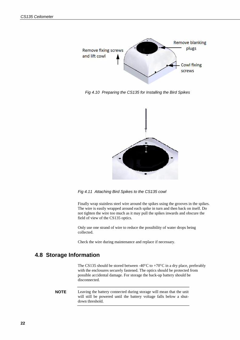
To install the bird spikes first remove the cowl and blanking plugs from the cowl
as shown in Fig 4.10. If the CS135 is an older unit without pre-existing holes then
it will be necessary to drill 4 holes each 4.5 mm diameter, evenly spaced around
the aperture and 10 mm in from the edge. Each spike is then inserted into the
holes, thread first, and nuts and washers attached and tightened, see Fig 4.11. Then
replace the cowl on the CS135.
WARNING
WARNING
CS135 Ceilometer
22
Fig 4.10 Preparing the CS135 for Installing the Bird Spikes
Fig 4.11 Attaching Bird Spikes to the CS135 cowl
Finally wrap stainless steel wire around the spikes using the grooves in the spikes.
The wire is easily wrapped around each spike in turn and then back on itself. Do
not tighten the wire too much as it may pull the spikes inwards and obscure the
field of view of the CS135 optics.
Only use one strand of wire to reduce the possibility of water drops being
collected.
Check the wire during maintenance and replace if necessary.
4.8 Storage Information
The CS135 should be stored between -40C to +70C in a dry place, preferably
with the enclosures securely fastened. The optics should be protected from
possible accidental damage. For storage the back-up battery should be
disconnected.
Leaving the battery connected during storage will mean that the unit
will still be powered until the battery voltage falls below a shut-
down threshold.
NOTE

Instruction Manual
23
If the CS135 has been stored below 0.0°C the start-up time will
progressively take longer - up to 10 minutes. Full accuracy will not
be achieved for an hour at -20°C.
The battery has a temperature range of -20°C to +50°C and should
be removed if the CS135 is to be stored outside this range.
5. Operation
5.1 Terminal mode
5.1.1 Entering/Exiting the CS135 Terminal Mode
The menu system is entered with the command OPEN Sensor_ID Password (The
menu will time out & close automatically if not used for 10 minutes).
Sensor_ID is the CS135 identification, a single ASCII character 0-9,a-f,A-F case
sensitive. The default is 0. If a password is set then it must be entered here
otherwise it can be omitted. The following text should now be displayed:
"CS135>". The CS135 is now ready for terminal mode commands.
The CS135 Commands are not case sensitive. The Parameters and/or password
following the command are case sensitive.
Example of the “open” command followed by the parameter “0”:
OPEN 0
Example of the open command with the password “Secret”:
OPEN 0 Secret
5.1.2 Terminal Mode Commands General
Table 5.1 gives a summary of the terminal mode commands available.
The CS135 can be setup and controlled by using the terminal interface where
discrete commands are sent. The terminal commands can be sent via a logger to
the CS135 removing the need for a local PC to set up the unit.
NOTE
NOTE

CS135 Ceilometer
24
The terminal emulators built into many Campbell Scientific software products can
also be used. Note however that DevConfig and PW Viewer cannot be used to
load a new operating system as this requires XMODEM protocol. One common,
freely available terminal emulator with this feature is called “TeraTerm” which is
easily available on the internet.
The following settings are used:
RS-232/422/485 interface (default) USB service port
RS-232 hand shaking Baud: rate 115200
Baud rate: 115200 Data bits: 8
Data bits: 8 Parity: none
Parity: none Stop bits: 1
Stop bits: 1 Flow control: none
Flow control: none
Ensure that if the baud rate of the unit has been adjusted and then the
corresponding bits per second value are entered in the port settings of the terminal
emulator. The CS135 should now be ready to accept commands.
Note: commands will always output all parameters on a new line after a CR LF &
then the CS135 prompt ‘CS135>’. If you only want to see parameter values
without changing them then enter the command without parameters. If a particular
parameter did not need changing then the parameter can be replaced with a comma
(,). Back space will abort the command.
5.1.3 Terminal mode command examples
The following text shows an example of setting up the CS135 serial port. This
example would set the serial port to RS-232 hand shaking at 115200 bps, 8 data
bits, no parity and if it was in RS-485 mode then a 100mS turn around delay.
serial 0 10 0 100
You could also type the following to obtain the same results as the RS-485 turn
around delay is not needed:
serial 0 10 0
If all you wish to do is change the data baud rate and nothing else you can replace
the first number, the mode parameter, with a ‘,’ as shown below.
serial , 10
Alternatively if you just wished to change the parity to 8-bits no parity then type
the following:
serial , , 0
You do not need to replace the remaining parameters with ‘,’ you only need to
replace the ones up to the parameter you wish to edit.
Remember to leave a space character between the command and the
parameters as shown in the examples.
NOTE
Instruction Manual
25
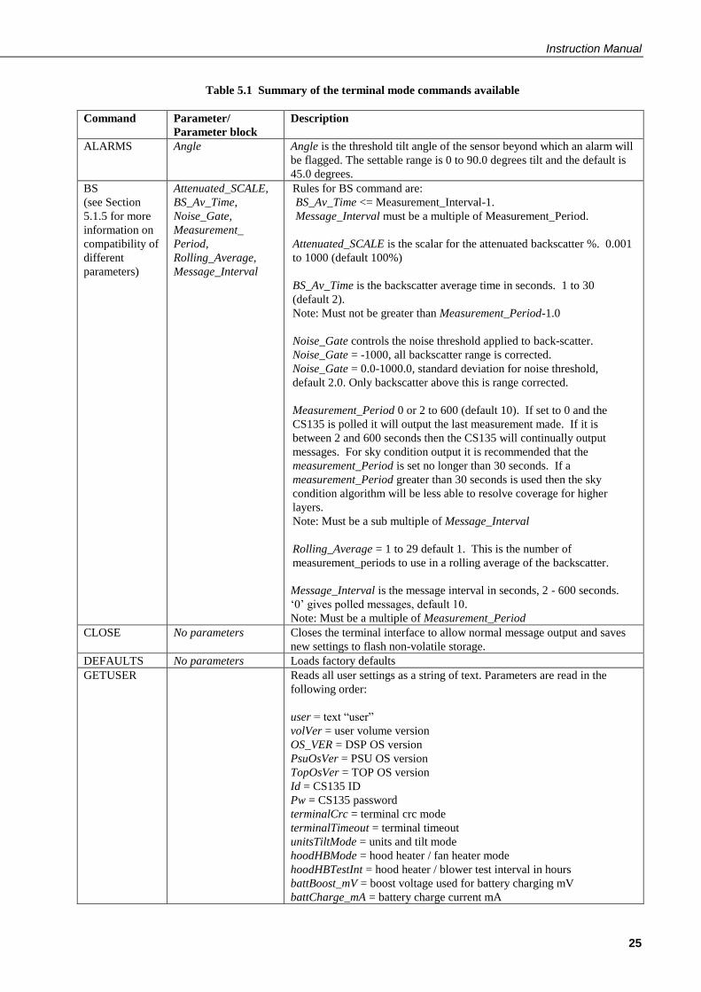
Table 5.1 Summary of the terminal mode commands available
Command Parameter/
Parameter block
Description
ALARMS Angle Angle is the threshold tilt angle of the sensor beyond which an alarm will
be flagged. The settable range is 0 to 90.0 degrees tilt and the default is
45.0 degrees.
BS
(see Section
5.1.5 for more
information on
compatibility of
different
parameters)
Attenuated_SCALE,
BS_Av_Time,
Noise_Gate,
Measurement_
Period,
Rolling_Average,
Message_Interval
Rules for BS command are:
BS_Av_Time <= Measurement_Interval-1.
Message_Interval must be a multiple of Measurement_Period.
Attenuated_SCALE is the scalar for the attenuated backscatter %. 0.001
to 1000 (default 100%)
BS_Av_Time is the backscatter average time in seconds. 1 to 30
(default 2).
Note: Must not be greater than Measurement_Period-1.0
Noise_Gate controls the noise threshold applied to back-scatter.
Noise_Gate = -1000, all backscatter range is corrected.
Noise_Gate = 0.0-1000.0, standard deviation for noise threshold,
default 2.0. Only backscatter above this is range corrected.
Measurement_Period 0 or 2 to 600 (default 10). If set to 0 and the
CS135 is polled it will output the last measurement made. If it is
between 2 and 600 seconds then the CS135 will continually output
messages. For sky condition output it is recommended that the
measurement_Period is set no longer than 30 seconds. If a
measurement_Period greater than 30 seconds is used then the sky
condition algorithm will be less able to resolve coverage for higher
layers.
Note: Must be a sub multiple of Message_Interval
Rolling_Average = 1 to 29 default 1. This is the number of
measurement_periods to use in a rolling average of the backscatter.
Message_Interval is the message interval in seconds, 2 - 600 seconds.
‘0’ gives polled messages, default 10.
Note: Must be a multiple of Measurement_Period
CLOSE No parameters Closes the terminal interface to allow normal message output and saves
new settings to flash non-volatile storage.
DEFAULTS No parameters Loads factory defaults
GETUSER Reads all user settings as a string of text. Parameters are read in the
following order:
user = text “user”
volVer = user volume version
OS_VER = DSP OS version
PsuOsVer = PSU OS version
TopOsVer = TOP OS version
Id = CS135 ID
Pw = CS135 password
terminalCrc = terminal crc mode
terminalTimeout = terminal timeout
unitsTiltMode = units and tilt mode
hoodHBMode = hood heater / fan heater mode
hoodHBTestInt = hood heater / blower test interval in hours
battBoost_mV = boost voltage used for battery charging mV
battCharge_mA = battery charge current mA

CS135 Ceilometer
26
psuPresent = PSU present switch
hoodHBNormSpeed = Fan voltage for normal speed mV
hoodHBHighSpeed = Fan voltage for high speed mV
hoodHBLowSpeed = Fan voltage for low speed mV
intHMode = internal heater mode
message[0] = fields for message 0
message[1] = fields for message 1
message[2] = fields for message 2
message[3] = fields for message 3
message[4] = fields for message 4
messagePeriod = output message period in seconds
heightOffset = height offset metres
bsAvTime = backscatter average time in seconds
laserMode = laser operation mode
laserPower = laser power
laserHeater = laser heater mode
attenuatedSCALE = attenuated backscatter scaling factor
logInterval = debug logging interval
measurementPeriod = measurement interval in seconds
serMode = serial port mode
baudSel = serial port baud rate mode
dataParityStop = serial port parity mode
rx2txTimeout = serial port RX to TX turnaround time
snrMarginBoundary = onset of backscatter detection threshold
snrMarginDetector = cloud detection threshold
alphaGuessEnd = cloud alpha guess at boundary
alphaMin = cloud detection alpha minimum
Vcld_D = cloud detection
delta_Vcld_D = cloud detection
vis_Av_T = cloud detection
alphaGuess = visibility initial alpha guess
ratioLevel = visibility ratio
alphaMin = visibility alpha minimum
cap = visibility cap in metres
tiltLimit = tilt limit in degrees used by alarms
noiseGate = attenuated backscatter noise gate mode
vvLimit_percent = sky condition report vertical visibility %
alphaGuessStart = cloud detection alpha guess at lowest height bin
dt = mixing layer height temporal filter minutes
dr = mixing layer height range filter metres
q1threshold = mixing layer height quality threshold 1
q2threshold = mixing layer height quality threshold 2
q3threshold = mixing layer height quality threshold 3
stdWidth = mixing layer height standard deviation width metres
CRC = 4 digit ASCII hex CRC calculated from the ‘u’ of user up-to but
not including the CRC using the standard CRC-16.
Note: Many of these parameters may not have been adjusted. This
command allows a reliable technique for copying full settings from one
CS135 to another with the ‘SETUSER’ command.
A typical response to the GETUSER command is:
>>>>>>>>>> COPY FROM START OF NEXT LINE >>>>>>>>>>
user 7 007638-6da 106 510 0 , 0 10 2 0 1 14520 400 1 1000 1000 2000
0 1 0 0 0 0 10 0.000E+00 2.000E+00 1 1.000E+00 0 1.000E+00 0 10 1
0 10 0 100 4.000E+00 6.000E+00 2.000E-03 2.500E-04 1.000E+03
2.200E+01 4.800E+03 1.000E-01 9.000E-01 2.500E-04 2.000E+03
4.500E+01 2.000E+00 50 2.00E-03 3.000E+01 1.500E+02 1.800E+00

Instruction Manual
27
5.000E+00 1.000E+01 150 98b2
<<<<<<<<<< TO START OF THIS LINE <<<<<<<<<<
HEATERS Hood,
Internal,
Laser,
Test_interval,
Sets or reads heater settings as follows:
Hood = 0, Hood blower and heater OFF
Hood = 1, Hood blower ON and heater OFF
Hood = 2, Hood blower ON and heater ON
Hood = 3, Hood blower and heater AUTO (default) – (See note (1)
below.
Internal = 0, Internal heater OFF
Internal = 1, Internal heater ON
Internal = 2, Internal heater AUTO (default)
Laser = 0, laser heater off
Laser = 1, laser heater on (default)
Test_interval = 1-168 hours (default 24h). Heater/Blower test interval
HELP No parameters Calls up a list of user commands with brief descriptions
HOFFSET Height_offset Height_offset is the offset to be added or subtracted in the range -1000 m
to +1000 m or -3281 ft to +3281 ft. Positive values are added to
measured height and negative values are subtracted from measured
height. The default is 0.
ID Sensor_ID Reads or sets the sensor ID, a single ASCII character, 0-9, a - z or A - Z,
case sensitive. Default ID = 0. Note that if a CT25K message is to be
used lower case letters are not allowed.
LASER Laser,
Laser_Power
Laser = 0, Laser off after power up (user must switch laser on).
Laser = 1, Laser on after power up (default).
Laser_Power = 20%-100%, default 100%.
LASEROFF No parameters Instructs the CS135 to turn the laser off until either a power cycle or the
sensor is instructed to turn the laser back on.
LASERON No parameters Instructs the CS135 to try and turn the laser on
LOADOS Module Loads new operating system into modules as follows:
Module =1, DSP.
Note: Operating systems earlier than 4 will need the boot loader
updating. Refer to Section 5.1.8 for more information.
Module =2, TOP
Module =3, PSU
Module =4, DSP, TOP & PSU as one file. This is only supported from
Operating system 8
This command must be sent using XMODEM protocol. Refer to Section
5.1.8 for more information.

CS135 Ceilometer
28
MCFG Message_Interval,
Message_ID_A,
Message_ID_B,
Message_ID_C,
Message_ID_D,
Message_ID_E
Set or read message configuration.
Message_Interval is the message interval in seconds, 2-600s.
0 gives polled messages, default 10.
Note: This command may affect measurement parameters within the ‘BS’
command. See Section 5.1.5
Message_ID is the message type to output between 0 and 999 (default
001). If Message_ID = 0 no message type will be output. Up to 5 messages
can be set. Please refer to Section 5.1.4.
MLH
(if available)
Temporal_Filter,
Range_Filter,
Std_Width,
Q1_Threshold,
Q2_Threshold,
Q3_Threshold,
Sets or reads parameters used in identifying Mixing Layer heights
Temporal_Filter = temporal filter half width used to filter data used by
mixing layer height algorithm in minutes. 1 to 40 (default 30 minutes)
Range_Filter = range filter half width used to smooth data used by mixing
layer height algorithm in metres or feet. 15 m to 600 m or 49 ft to 1969 ft
(default 150 m or 492 ft)
Std_Width = range half width used to calculate standard deviation of the
slope in metres or feet. 10 m to 400 m or 33 ft to 1312 ft (default 150 m or
492 ft)
Q1_Threshold = SNR threshold for quality level 1 mixing layer height
output. 1.0 to 30.0 (default 1.8)
Q2_Threshold = SNR threshold for quality level 2 mixing layer height
output. 1.0 to 30.0 (default 5.0)
Q3_Threshold = SNR threshold for quality level 3 mixing layer height
output. 1.0 to 30.0 (default 10.0)
OPEN ID,
Password
Opens the CS135 terminal mode.
ID = Sensor ID as per the terminal command “ID”
Password = The sensors user password as per the terminal command
“PASSWORD”. The default is no password.
PASSWORD Password Sets or clears a password from 1 to 10 characters in length. Valid ASCII
characters 0-9, a - z or A – Z and letters are case sensitive. Typing the
command PASSWORD without any parameters clears the password. The
default is no password.
POLL Sensor_ID
Message_ID
Requests the message Message_ID from the sensor Sensor_ID.
Refer to Section 5.1.7 for more information on this command
Note: If Message_ID is omitted the CS135 outputs the message configured
by MCFG.
POWEROFF No parameters This will prepare the PSU to power down the CS135 even if the battery is
connected. As soon as the mains supply is disconnected the CS135 will
power off and NOT run on battery back-up. The CS135 can be re-
activated with battery back-up enabled by re-connecting the mains supply.
You will be asked to confirm.
REBOOT No parameters Forces a system reboot. This will restore previously saved user settings.
Any unsaved changes will be lost. (Settings are saved in terminal mode
when the command CLOSE is typed, which exits the terminal mode).
SCCAL No parameters but
user interaction
required
Stratocumulus backscatter calibration.
This requires a human observer to confirm a stable Stratocumulus cloud
layer between 250 m to 2500 m without holes, precipitation or reduced
visibility and has been stable for at least 10 minutes prior to running this
command. See Section 5.1.9 for more information.
SERIAL Mode,
Baud,
Set or read the serial port
Mode = 0, RS-232

Instruction Manual
29
Bits_Parity,
Delay
Mode = 1, RS-232
Mode = 2, RS-485, full duplex.
Mode = 3, RS-485, half duplex.
Mode = 4, Reserved.
Mode = 5, RS-422, full duplex.
Baud = 0, 300 baud.
Baud = 1, 600 baud.
Baud = 2, 1200 baud.
Baud = 3, 2400 baud.
Baud = 4, 4800 baud.
Baud = 5, 9600 baud.
Baud = 6, 19200 baud.
Baud = 7, 38400 baud.
Baud = 8, 57600 baud.
Baud = 9, 76800 baud.
Baud = 10, 115200 baud (default).
Bits_Parity = 0, 8 bits, no parity, 1 stop bit (default).
Bits_Parity = 1, 7 bits, even parity, 1 stop bit.
Bits_Parity = 2, 7 bits, odd parity, 1 stop bit.
Delay is the delay time in mS to TX (RS-485 half-duplex mode only).
Range 0-100 mS, default 100 mS.
SERVICE No parameters but
user intervention
required
Performs a service procedure
SETUSER String Load all user settings as a string of text.
(not changed) = parameter will not be updated and the previously set value
will persist.
String =
user (not changed)
volVer = user volume version (not changed)
OS_VER = DSP OS version (not changed)
PsuOsVer = PSU OS version (not changed)
TopOsVer = TOP OS version (not changed)
Id = CS135 ID (not changed)
Pw = CS135 password (not changed)
terminalCrc = terminal crc mode
terminalTimeout = terminal timeout
unitsTiltMode = units and tilt mode
hoodHBMode = hood heater / fan heater mode
hoodHBTestInt = hood heater / blower test interval in hours
battBoost_mV = boost voltage used for battery charging mV
battCharge_mA = battery charge current mA
psuPresent = PSU present switch
hoodHBNormSpeed = Fan voltage for normal speed mV
hoodHBHighSpeed = Fan voltage for high speed mV
hoodHBLowSpeed = Fan voltage for low speed mV
intHMode = internal heater mode
message[0] = fields for message 0
message[1] = fields for message 1
message[2] = fields for message 2
message[3] = fields for message 3
message[4] = fields for message 4
messagePeriod = output message period in seconds
heightOffset = height offset metres
bsAvTime = backscatter average time in seconds
laserMode = laser operation mode

CS135 Ceilometer
30
laserPower = laser power
laserHeater = laser heater mode
attenuatedSCALE = attenuated backscatter scaling factor
logInterval = debug logging interval
measurementPeriod = measurement interval in seconds
serMode = serial port mode
baudSel = serial port baud rate mode
dataParityStop = serial port parity mode
rx2txTimeout = serial port RX to TX turnaround time
snrMarginBoundary = onset of back-scatter detection threshold
snrMarginDetector = cloud detection threshold
alphaGuessEnd = cloud alpha guess at boundary
alphaMin = cloud detection alpha minimum
Vcld_D = cloud detection
delta_Vcld_D = cloud detection
vis_Av_T = cloud detection
alphaGuess = visibility initial alpha guess
ratioLevel = visibility ratio
alphaMin = visibility alpha minimum
cap = visibility cap in metres
tiltLimit = tilt limit in degrees used by alarms
noiseGate = attenuated backscatter noise gate mode
vvLimit_percent = sky condition report vertical visibility %
alphaGuessStart = cloud detection alpha guess at lowest height bin
dt = mixing layer height temporal filter minutes
dr = mixing layer height range filter metres
q1threshold = mixing layer height quality threshold 1
q2threshold = mixing layer height quality threshold 2
q3threshold = mixing layer height quality threshold 3
stdWidth = mixing layer height standard deviation width metres
CRC = 4 digit ASCII hex CRC calculated from the ‘u’ of user up-to but not
including the CRC using the standard CRC-16-CCITT.
Note: String is added as text and should be added as a “cut and paste” from
a stored file.
STATUS No parameters Outputs CS135, serial number, ID, DSP OS version, Time & Date, DSP
version, TOP OS version, PSU OS version, watch dog counts, serial
parameters, blower heater mode, internal heater mode, message
parameters, tilt angle, units, temperature/humidity, temperatures, supply
voltages, height offset, visibility cap, laser run days, window parameters,
backscatter parameters, MLH parameters, features, alarms, warnings &
status.
Note: Refer to Section 5.1.6 for more information on this command
TERMINAL Terminal,
Timeout
Sets CRC-16-CCITT checking and the user terminal time out.
Terminal = 0, CRC-16-CCITT off (default).
Terminal = 1, CRC-16-CCITT on (all terminal commands need a CRC.
See Section 5.1.10 for details).
Timeout is the delay in minutes from 1 to 15 where the terminal will
automatically close if no characters are sent to the CS135. The default is
10 minutes.

Instruction Manual
31
TIME Date_Time
Date is in the format yyyy/mm/dd
Time is in the format hh:mm:ss
yyyy=year, mm=month, dd=day
hh=hours, mm=minutes, ss=seconds
(i.e. time 2013/05/25 10:00:00, would set the date and time to May 25th
2013 at 10:00:00)
Note: The set time could drift by up to ±14 seconds a day.
UNITS Units Sets measurement units and tilt correction.
Units = 0, metres corrected by tilt.
Units = 1, metres not corrected by tilt.
Units = 2, feet corrected by tilt (default).
Units = 3, feet not corrected by tilt.
UNLOCK Key Key = a 12 digit ASCII hex key provided by CSL to unlock pay-for
features
VIS Cap Cap is the vertical visibility maximum range 100 to 10000 in metres or 328
to 32808 in feet (default 2000 m or 6561 ft).
Note (1)
If AUTO is set then the Heater / blower will activate at 80°C if (sky condition > 1 okta coverage) or (cloud height
< 3 Km AND sky condition > 1 okta coverage) OR window Tx < 80% OR precipitation detected. When the event has
passed the blower/heater will remain active at 80°C for a further 15 minutes before going into a fan-off state and
heater temperature average of approximately 40°C ready to be activated again.
5.1.4 MCFG command message types
The MCFG commands “Message_ID_x” parameter defines the following output
types. Refer to Section 6 for further information on message output types.
Message_ID_x type Description
000 No message
001 (default) Campbell Scientific Message 1, no sky condition, no profile data
002 Campbell Scientific Message 2, no sky condition, profile data, 2048 range bins, 5 m resolution
003 Campbell Scientific Message 3, sky condition, no profile data
004 Campbell Scientific Message 4, sky condition and profile data, 2048 range bins, 5 m resolution
005* Campbell Scientific Message 5, sky condition, no profile data, mixing layer height
006* Campbell Scientific Message 6, sky condition, profile data, 2048 range bins, 5 m resolution,
mixing layer height
101 CL31 Message 1, 770 range bins, 10 m resolution
102 CL31 Message 1, 385 range bins, 20 m resolution
103 CL31 Message 1, 1500 range bins, 5 m resolution
104 CL31 Message 1, 770 range bins, 5 m resolution
105 CL31 Message 1, No profile data
106 CL31 Message 1, Full CS135 output, 2048 range bins, 5 m resolution
107 CL31 Message 2, 770 range bins, 10 m resolution
108 CL31 Message 2, 385 range bins, 20 m resolution
109 CL31 Message 2, 1500 range bins, 5 m resolution
110 CL31 Message 2, 770 range bins, 5 m resolution
111 CL31 Message 2, No profile data
112 CL31 Message 2, Full CS135 output, 2048 range bins, 5 m resolution
113 CT25K message 1
114 CT25K message 6
* only available if MLH option is active

CS135 Ceilometer
32
5.1.5 Measurement and message intervals
The message interval is the interval in seconds, 2 to 10 or 20 to 600 in steps of 10,
between automatic message transmission (‘0’ gives polled messages). The default
is 10 meaning a message will be sent automatically every 10 seconds. It must be a
multiple of measurement period.
The backscatter average time, BS_Av_Time, is the period over which the laser is
firing and taking measurements.
The measurement period is the time interval between the start of a period of
BS_Av_Time over which the laser fires and the start of the next. This period must
be long enough to include the backscatter average time and some processing time.
It should be 2 seconds at least and a sub-multiple of the message interval.
Rolling average is the periods used to calculate each scatter value that is either
used in a profile message or in a calculation of cloud height.
The message interval may affect measurement parameters allowed within the ‘BS’
command (‘BS’ can set non-standard measurement parameters) as follows:
If Message_interval = Measurement_Period = 2 (lowest values allowed)
Then BS_Av_Time must = 1 and Rolling_Average = 1
If 2 < Message_interval < 10
Then Measurement_Period must equal Message_interval, BS_Av_Time must
equal 2 and Rolling_Average must equal 1
Yellow means laser firing
In this case the CS135 sends a message every 2 seconds based on 1 measurement
averaged over 1 second at 2 second intervals.
Each message is based on a single 1 second period of average data.
1s
2s
2s
Averaging Period = 1s (BS_AV_Time)
Measurement Period = 2s
Message Interval = 2s
In this case the CS135 sends a message every 30 seconds based on 3
measurements taking 2 seconds at 10 second intervals.
Each message is based on a single 2 second period of average data.
2s
10s
30s
Averaging Period = 2s (BS_AV_Time)
Measurement Period = 10s
Message Interval = 30s

Instruction Manual
33
In this case the CS135 sends a message every 30 seconds based on 3
measurements taking 2 seconds at 10 second intervals.
Each message is based on three 2 second period of average data.
2s
10s
30s
Averaging Period = 2s (BS_AV_Time)
Measurement Period = 10s
Message Interval = 30s
Rolling average = 3
In this case the CS135 sends a message every 14 seconds based on 1 measurement
taking 4 seconds over a 14 second interval.
Each message is based on a single 4 second period of average data.
4s
14s 14s 14s 14s
14s 14s 14s 14s
Averaging Period = 4s (BS_AV_Time)
Measurement Period = 14s
Message Interval = 14s
This message cannot be set up using the MCFG command alone.
The BS command has to be used as follows:
BS_Av_Time (averaging period) has to be set to 4, not the default value.

CS135 Ceilometer
34
5.1.6 STATUS command
The STATUS command returns the following information:
Line Example line output
1 Identification CS135 SN1000 ID 0
Description of the line sections
Section Description
CS135 Product name
SN1000 Sensor serial number
ID 0 Sensor identification number
Line Example line output
2 Date Time 2012/01/10 11:39:46
Description of the line sections
Section Description
2012/01/10 Date in the format yyyy/mm/dd
11:39:46 Time in the format hh:mm:ss
Line Example line output
3 DSP_OS A
Description of the line sections
Section Description
A DSP OS revision number
Line Example line output
4 TOP_OS 1
Description of the line sections
Section Description
A TOP board OS revision number
Line Example line output
5 PSU_OS 1
Description of the line sections
Section Description
A PSU board OS revision number
Line Example line output
6 Watchdog A
Description of the line sections
Section Description
A Watchdog counter for unscheduled system resets
Line Example line output
7 Serial A B C D
Description of the line sections
Section Description
A Serial mode (Note: Refer to the SERIAL command)
B Serial baud rate (Note: Refer to the SERIAL command)
C Parity and stop bits (Note: Refer to the SERIAL command)
D Receive to transmit delay time in RS-485 mode (Note: Refer to the SERIAL
command)

Instruction Manual
35
Line Example line output
8 Heaters A B C D
Description of the line sections
Section Description
A Hood blower mode
B Internal heater mode
C Laser heater mode
D Heater/blower test interval in hours
Line Example line output
9 MCFG X A B C D E
Description of the line sections
Section Description
X Message interval (Note: Refer to the MCFG command)
A Message ID A (Note: Refer to the MCFG command)
B Message ID B (Note: Refer to the MCFG command)
C Message ID C (Note: Refer to the MCFG command)
D Message ID D (Note: Refer to the MCFG command)
E Message ID E (Note: Refer to the MCFG command)
Line Example line output
10 Angle A B C
Description of the line sections
Section Description
A X axis tilt
B Y axis tilt
C Beam angle from vertical
Line Example line output
11 Units A
Description of the line sections
Section Description
A Measurement units and tilt correction. (Note: Refer to the UNITS command)
Line Example line output
12 TRH A B C
Description of the line sections
Section Description
A Sensor internal temperature reading in degrees Celsius.
B Sensor internal humidity reading as a percentage
C Sensors internal dew point value in degrees Celsius
Line Example line output
13 T A B C D E F
Description of the line sections
Section Description
A External fan blower assembly temperature in degrees Celsius
B PSU internal temperature in degrees Celsius
C TOP board laser monitor temperature in degrees Celsius
D TOP board calibration LED temperature in degrees Celsius
E Laser module temperature in degrees Celsius
F Photo diode module temperature in degrees Celsius
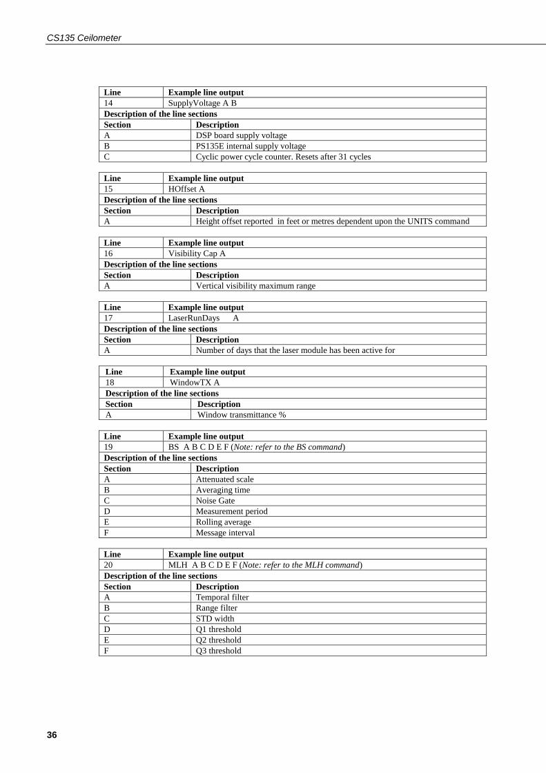
CS135 Ceilometer
36
Line Example line output
14 SupplyVoltage A B
Description of the line sections
Section Description
A DSP board supply voltage
B PS135E internal supply voltage
C Cyclic power cycle counter. Resets after 31 cycles
Line Example line output
15 HOffset A
Description of the line sections
Section Description
A Height offset reported in feet or metres dependent upon the UNITS command
Line Example line output
16 Visibility Cap A
Description of the line sections
Section Description
A Vertical visibility maximum range
Line Example line output
17 LaserRunDays A
Description of the line sections
Section Description
A Number of days that the laser module has been active for
Line Example line output
18 WindowTX A
Description of the line sections
Section Description
A Window transmittance %
Line Example line output
19 BS A B C D E F (Note: refer to the BS command)
Description of the line sections
Section Description
A Attenuated scale
B Averaging time
C Noise Gate
D Measurement period
E Rolling average
F Message interval
Line Example line output
20 MLH A B C D E F (Note: refer to the MLH command)
Description of the line sections
Section Description
A Temporal filter
B Range filter
C STD width
D Q1 threshold
E Q2 threshold
F Q3 threshold
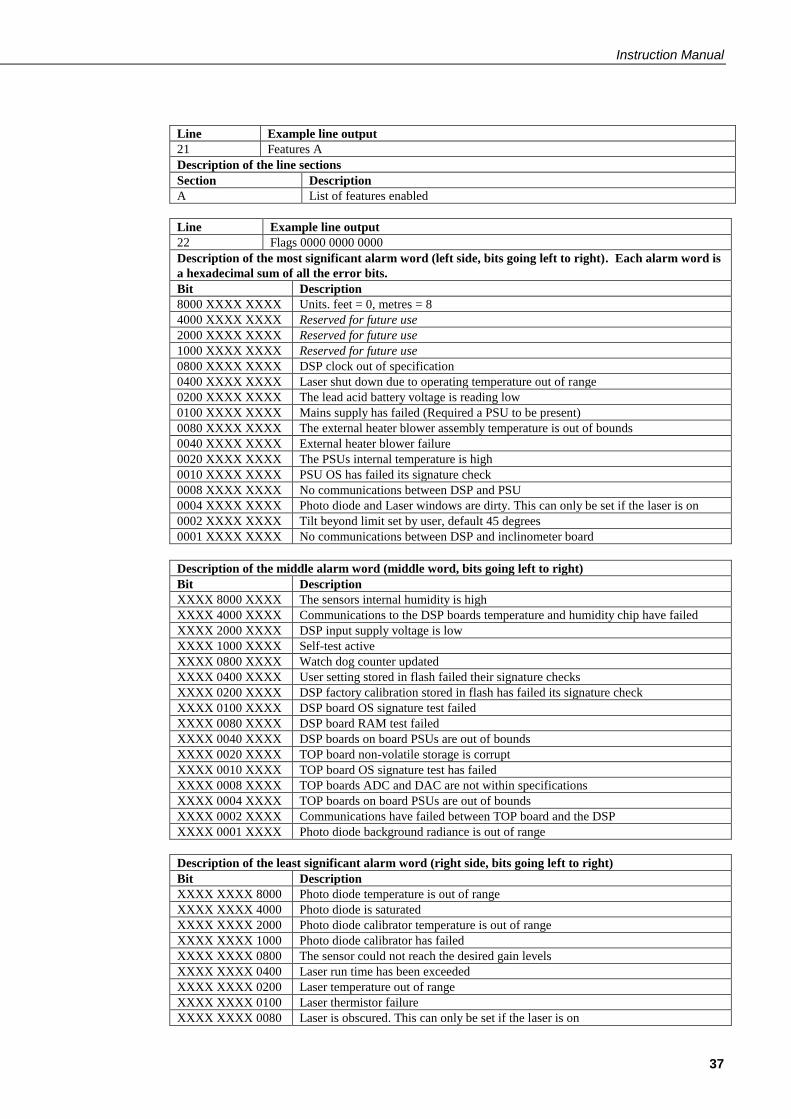
Instruction Manual
37
Line Example line output
21 Features A
Description of the line sections
Section Description
A List of features enabled
Line Example line output
22 Flags 0000 0000 0000
Description of the most significant alarm word (left side, bits going left to right). Each alarm word is
a hexadecimal sum of all the error bits.
Bit Description
8000 XXXX XXXX Units. feet = 0, metres = 8
4000 XXXX XXXX Reserved for future use
2000 XXXX XXXX Reserved for future use
1000 XXXX XXXX Reserved for future use
0800 XXXX XXXX DSP clock out of specification
0400 XXXX XXXX Laser shut down due to operating temperature out of range
0200 XXXX XXXX The lead acid battery voltage is reading low
0100 XXXX XXXX Mains supply has failed (Required a PSU to be present)
0080 XXXX XXXX The external heater blower assembly temperature is out of bounds
0040 XXXX XXXX External heater blower failure
0020 XXXX XXXX The PSUs internal temperature is high
0010 XXXX XXXX PSU OS has failed its signature check
0008 XXXX XXXX No communications between DSP and PSU
0004 XXXX XXXX Photo diode and Laser windows are dirty. This can only be set if the laser is on
0002 XXXX XXXX Tilt beyond limit set by user, default 45 degrees
0001 XXXX XXXX No communications between DSP and inclinometer board
Description of the middle alarm word (middle word, bits going left to right)
Bit Description
XXXX 8000 XXXX The sensors internal humidity is high
XXXX 4000 XXXX Communications to the DSP boards temperature and humidity chip have failed
XXXX 2000 XXXX DSP input supply voltage is low
XXXX 1000 XXXX Self-test active
XXXX 0800 XXXX Watch dog counter updated
XXXX 0400 XXXX User setting stored in flash failed their signature checks
XXXX 0200 XXXX DSP factory calibration stored in flash has failed its signature check
XXXX 0100 XXXX DSP board OS signature test failed
XXXX 0080 XXXX DSP board RAM test failed
XXXX 0040 XXXX DSP boards on board PSUs are out of bounds
XXXX 0020 XXXX TOP board non-volatile storage is corrupt
XXXX 0010 XXXX TOP board OS signature test has failed
XXXX 0008 XXXX TOP boards ADC and DAC are not within specifications
XXXX 0004 XXXX TOP boards on board PSUs are out of bounds
XXXX 0002 XXXX Communications have failed between TOP board and the DSP
XXXX 0001 XXXX Photo diode background radiance is out of range
Description of the least significant alarm word (right side, bits going left to right)
Bit Description
XXXX XXXX 8000 Photo diode temperature is out of range
XXXX XXXX 4000 Photo diode is saturated
XXXX XXXX 2000 Photo diode calibrator temperature is out of range
XXXX XXXX 1000 Photo diode calibrator has failed
XXXX XXXX 0800 The sensor could not reach the desired gain levels
XXXX XXXX 0400 Laser run time has been exceeded
XXXX XXXX 0200 Laser temperature out of range
XXXX XXXX 0100 Laser thermistor failure
XXXX XXXX 0080 Laser is obscured. This can only be set if the laser is on
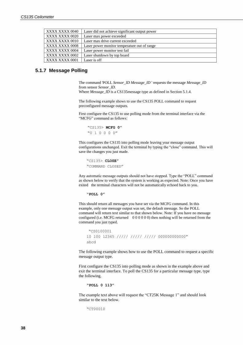
CS135 Ceilometer
38
XXXX XXXX 0040 Laser did not achieve significant output power
XXXX XXXX 0020 Laser max power exceeded
XXXX XXXX 0010 Laser max drive current exceeded
XXXX XXXX 0008 Laser power monitor temperature out of range
XXXX XXXX 0004 Laser power monitor test fail
XXXX XXXX 0002 Laser shutdown by top board
XXXX XXXX 0001 Laser is off
5.1.7 Message Polling
The command 'POLL Sensor_ID Message_ID ' requests the message Message_ID
from sensor Sensor_ID.
Where Message_ID is a CS135message type as defined in Section 5.1.4.
The following example shows to use the CS135 POLL command to request
preconfigured message outputs.
First configure the CS135 to use polling mode from the terminal interface via the
“MCFG” command as follows:
“CS135> MCFG 0”
“0 1 0 0 0 0”
This configures the CS135 into polling mode leaving your message output
configurations unchanged. Exit the terminal by typing the “close” command. This will
save the changes you just made.
“CS135> CLOSE”
“COMMAND CLOSED”
Any automatic message outputs should not have stopped. Type the “POLL” command
as shown below to verify that the system is working as expected. Note: Once you have
exited the terminal characters will not be automatically echoed back to you.
“POLL 0”
This should return all messages you have set via the MCFG command. In this
example, only one message output was set, the default message. So the POLL
command will return text similar to that shown below. Note: If you have no message
configured (i.e. MCFG returned 0 0 0 0 0 0) then nothing will be returned from the
command you just typed.
“CS0100001
10 100 12345 ///// ///// ///// 000000000000”
abcd
The following example shows how to use the POLL command to request a specific
message output type.
First configure the CS135 into polling mode as shown in the example above and
exit the terminal interface. To poll the CS135 for a particular message type, type
the following.
“POLL 0 113”
The example text above will request the “CT25K Message 1” and should look
similar to the text below.
“CT00010

Instruction Manual
39
10 12345 ///// ///// 00000f80”
5.1.8 Loading a New Operating System (OS)
A new OS can be entered with the LOADOS module command. Note three
different modules each have their own OS. The parameter module loads a new
operating system into different modules as follows:
Module =1, DSP (file type *. ldr)
Module =2, TOP (file type *. hex)
Module =3, PSU (file type*. hex)
Module =4, DSP, TOP & PSU as one file, type *.ldr. This is the usual method.
The new OS must be sent using xmodem protocol.
To load a new operating system:
Enter terminal mode by typing “Open 0” (for a sensor with the default ID “0”)
This will return the prompt “CS135>”
Type the command “LOADOS4”
The CS135 will respond:
“Load OS into DSP
DO NOT REMOVE POWER DURING OS UPDATE!!!
Waiting for xmodem”
At this point use your terminal emulator to send the appropriate file.
Loading the OS could take a few minutes.
When the process is complete the CS135 will return the message:
“Wait 40 sec for OS to restart”
after which it will resume operation according to the previously set operating
parameters. It will no longer be in terminal mode.
To load a new operating system into a CS135 with an OS between 4 and 7
Enter terminal mode by typing “Open 0” (for a sensor with the default ID “0”)
This will return the prompt “CS135>”
Type the command “LOADOS 1”
The CS135 will respond:
“Load OS into DSP
DO NOT REMOVE POWER DURING OS UPDATE!!!
Waiting for xmodem”
At this point use your terminal emulator to send the *.ldr file using xmodem
protocol.
Loading the OS could take a few minutes.
When the process is complete the CS135 will return the message:
“Wait 40 sec for OS to restart” after which it will resume operation according
to the previously set operating parameters. It will no longer be in terminal
mode.
NOTE

CS135 Ceilometer
40
DO NOT REBOOT THE CS135 AT THIS POINT
Again enter terminal mode by typing “Open 0” (for a sensor with the default ID
“0”)
This will return the prompt “CS135>”
This time type the command “LOADOS 4”
The CS135 will respond:
“Load OS into DSP
DO NOT REMOVE POWER DURING OS UPDATE!!!
Waiting for xmodem”
At this point again use your terminal emulator to send the *.ldr file using
xmodem protocol.
Loading the OS could take a few minutes.
When the process is complete the CS135 will return the message:
“Wait 40 sec for OS to restart” after which it will resume operation according
to the previously set operating parameters. It will no longer be in terminal
mode.
To load a new operating system into a CS135 with an OS between 1 and 3
Operating systems earlier than 4 will need the boot loader updating, use the
LOADOS 1 command, not LOADOS 4, before a new DSP OS can be uploaded
so the first time the OS is loaded a verify error will be reported (this is normal)
as follows:
“Error writing word 32768
Verify OS
Error verifying word 327680 37020 4236”
You will then need to `reboot’ and then load the OS using the terminal
command `LOADOS 4’ to correctly load the OS without errors.
The process is as follows:
Enter terminal mode by typing “Open 0” (for a sensor with the default ID “0”)
This will return the prompt “CS135>”
Type the command “LOADOS 1”
The CS135 will respond:
“Load OS into DSP
DO NOT REMOVE POWER DURING OS UPDATE!!!
Waiting for xmodem”
At this point use your terminal emulator to send the *.ldr file using xmodem
protocol.
Loading the OS could take a few minutes.
When the process is complete the CS135 will return the message:
“Error writing word 32768
Verify OS
Error verifying word 327680 37020 4236”
NOW REBOOT THE CS135 USING THE “REBOOT” COMMAND
Wait 40 sec for OS to restart after which it will resume operation according to
the previously set operating parameters. It will no longer be in terminal mode.
Again enter terminal mode by typing “Open 0” (for a sensor with the default ID
“0”)
This will return the prompt “CS135>”
This time type the command “LOADOS 4”

Instruction Manual
41
The CS135 will respond:
“Load OS into DSP
DO NOT REMOVE POWER DURING OS UPDATE!!!
Waiting for xmodem”
At this point again use your terminal emulator to send the *.ldr file again using
xmodem protocol .
Loading the OS could take a few minutes.
When the process is complete the CS135 will return the message:
“Wait 40 sec for OS to restart” after which it will resume operation according
to the previously set operating parameters. It will no longer be in terminal
mode.
It is good practice to re-boot the sensor after loading a new OS.
5.1.9 Stratocumulus backscatter calibration
The command ‘SCCAL’ allows a simple Stratocumulus backscatter calibration of
the scatter coefficient measurements. This requires a human observer to confirm a
stable Stratocumulus cloud layer between 250 m to 2500 m without holes,
precipitation or reduced visibility and has been stable for at least 10 minutes prior
to running this command.
Measurement_Period should be set to 10s. See Table 5.1.
A detailed description of this technique is given in: - Ewan J. O’Connor, Anthony
J. Illingworth, and Robin J. Hogan, 2004: A Technique for Autocalibration of
Cloud Lidar. Journal of Atmospheric and Ocean Technology, 21, pp 777 - 786
Enter terminal mode by typing “Open 0” (for a sensor with the default ID “0”)
This will return the prompt “CS135>”
Type the command “SCCAL”
The CS135 will respond:
“Stratocumulus calibration.
Enter height above sea level (m)? Press enter to continue:”
Enter the sensor height above sea level, for example 70 m and type return.
The CS135 will respond “70 m entered, is this correct? 'Y', 'N' or `Q’ ”
Type “Y” to confirm or if you have entered an incorrect number type “N” and you
will be able to replace it. Typing “Q” will quit the calibration and return to the
terminal command prompt.
The CS135 will now respond:
“For correct calibration a trained human observer must confirm that the layer is
between 250 m to 2500 m and has been stable for at least 10 minutes without
drizzle. Has the Stratocumulus been stable for at least 10 minutes? 'Y' or 'N' ”
To confirm type “Y”
The CS135 will respond:

CS135 Ceilometer
42
“Old Stratocumulus calibration = 0.0282
New Stratocumulus calibration parameters = 0.0258 70 1328
Do you want to apply this calibration? 'Y' or 'N' ”
In this example 70 is the height of the sensor above sea level previously entered
and 1210 is the cloud base in metres above the sensor.
As a very rough guide if the calibration factor has changed by less than 20% there
is probably no need to change. If it has changed by a factor of 2 it is wise to run
the service routine on the sensor (See 5.1.11).
Type “Y” to confirm and the CS135 will respond:
“Calibration saved.”
The following error messages may appear during the process.
Error ... Time out.
Error ... Cloud not detected or height not within limits (250 m to 2500 m).
Try again when layer is stable.
Error ... Not enough data available try again in 10 minutes.
5.1.10 CRC-16 Codes on terminal commands
If CRC-16 on mode is set using the “Terminal” command, all terminal commands
need a CRC-16. A semi-colon is used to indicate start of the CRC-16 in 4 byte
ASCII hex, for example “open 0;d2d5”. The CRC-16 is calculated either from the
start of a new line or after a [STX] up to but not including the semi-colon. ETX
can follow the CRC-16 if required.
The valid CRC-16 can be found for any command by entering the command with
the 4 character CRC-16 after the semi-colon replaced with “????”. For example
entering “open 0;????” gives the response “[CRLF]CRC>D2D5<CRC[CRLF” so
d2d5 is the CRC-16.
The CRC-16 is not case sensitive.
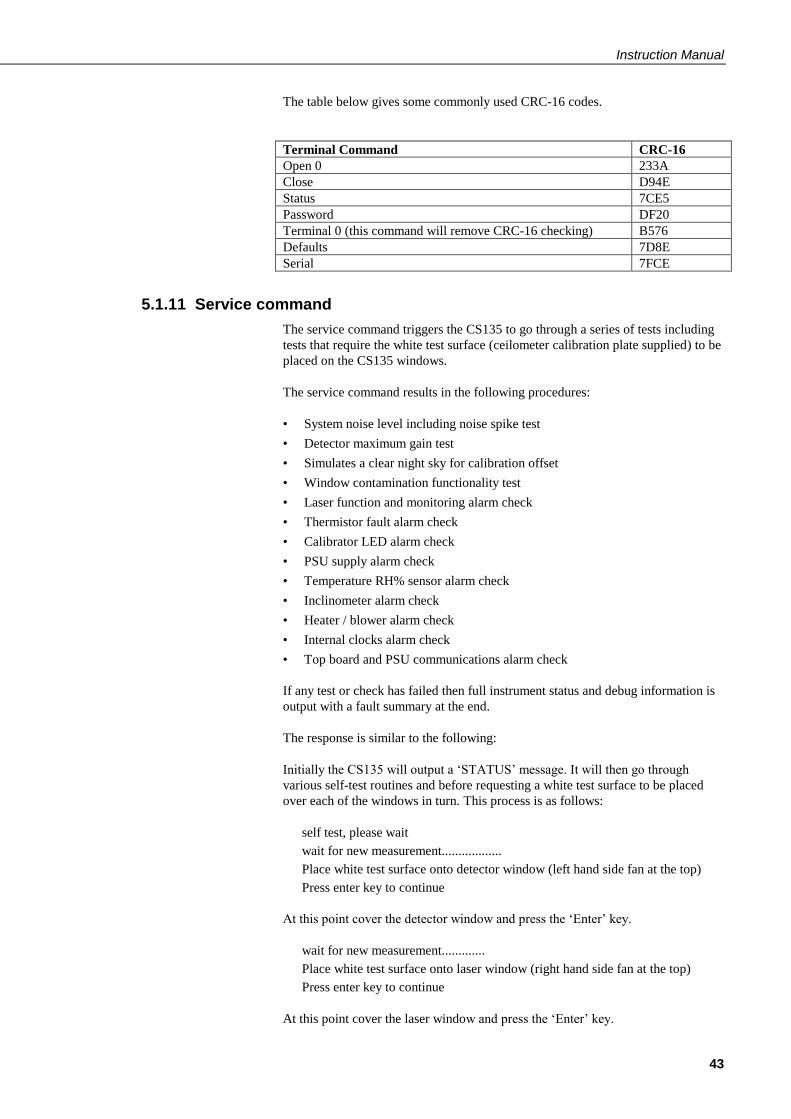
Instruction Manual
43
The table below gives some commonly used CRC-16 codes.
Terminal Command CRC-16
Open 0 233A
Close D94E
Status 7CE5
Password DF20
Terminal 0 (this command will remove CRC-16 checking) B576
Defaults 7D8E
Serial 7FCE
5.1.11 Service command
The service command triggers the CS135 to go through a series of tests including
tests that require the white test surface (ceilometer calibration plate supplied) to be
placed on the CS135 windows.
The service command results in the following procedures:
• System noise level including noise spike test
• Detector maximum gain test
• Simulates a clear night sky for calibration offset
• Window contamination functionality test
• Laser function and monitoring alarm check
• Thermistor fault alarm check
• Calibrator LED alarm check
• PSU supply alarm check
• Temperature RH% sensor alarm check
• Inclinometer alarm check
• Heater / blower alarm check
• Internal clocks alarm check
• Top board and PSU communications alarm check
If any test or check has failed then full instrument status and debug information is
output with a fault summary at the end.
The response is similar to the following:
Initially the CS135 will output a ‘STATUS’ message. It will then go through
various self-test routines and before requesting a white test surface to be placed
over each of the windows in turn. This process is as follows:
self test, please wait
wait for new measurement..................
Place white test surface onto detector window (left hand side fan at the top)
Press enter key to continue
At this point cover the detector window and press the ‘Enter’ key.
wait for new measurement.............
Place white test surface onto laser window (right hand side fan at the top)
Press enter key to continue
At this point cover the laser window and press the ‘Enter’ key.

CS135 Ceilometer
44
wait for new measurement.......................
Remove white test surface from laser window. Press enter key to continue
When this is complete the CS135 will output a string of diagnostic data similar.
This can be very useful for a Campbell Scientific engineer investigating problems
with the CS135.
Finally the CS135 will list any faults found as shown below:
******** CS135 FAULT list ********
FAULT - external heater/blower thermistor
FAULT - detector dirty windows with white test surface
FAULT - max APD gain not achieved
Otherwise it will report the following message:
******** CS135 has PASSED all tests ********
5.1.12 Locked features
Optional features such as Mixing Layer Height assessment are protected by a
`key’. They are enabled by typing the command `UNLOCK’ followed by the key.
This is specific to the individual CS135 and only has to be entered once.
5.2 Restoring Factory Defaults
Factory defaults can be restored using the terminal mode command
“DEFAULTS”. Alternatively, they can be set using a push switch on the DSP as
shown in Fig 5.1. The cover and enclosure lid first have to be removed. Please
refer to Sections 4.6.1 and 4.6.2.
If the switch is pushed for four seconds the CS135 will reboot in exactly the same
way as the REBOOT terminal command. If it is held closed while the CS135 is
powered off and on again it will return to factory defaults. Note that to power cycle
the CS135 the battery has to be disconnected as well as switching the main power
off and on.
Fig 5.1 Restoring Factory Defaults

Instruction Manual
45
Opening the access door MUST be carried out by a competent
person.
5.3 LED Indicator
Figure 5.2 LED indicator
A green LED is visible through the window, see Fig 5.2. It will give 0.5 second
flashes as follows:
1 flash every 10 seconds = OK, no fault
2 flashes every 10 seconds = warning (possible degraded performance)
3 flashes every 10 seconds = alarm (measurements not possible)
6. Messages
6.1 Data Messages General
The CS135 can provide a variety of data message types to allow efficient output of
data. Not all messages provide the full information available but these messages
may be more efficient in terms of data storage and transmission.
CL31 and CT25K messages follow formats used by common existing CL31 and
CT25K sensors allowing easier replacement or network expansion.
6.2 Checksums used in CS135 messages
This is based on the CCITT-16 CRC-16 with the output XOR’d with Hex 0xFFFF
and outputs a two byte CRC-16 in hex format (four ASCII characters). The CRC-
16 is calculated on all characters after the SOH character up to and including the
ETX character.
The following example ‘C’ code calculates the CS135 checksum.
Note - `shorts’ are 16 bits long and `ints’ are 32 bits long.
NOTE

CS135 Ceilometer
46
// ----------------------------------------------------
------------
// Calculate CRC-16
// buf is a pointer to the input string
// len is the length of the input string
// ----------------------------------------------------
------------
unsigned short crc16(char *buffer, int length)
{
unsigned short crc;
unsigned short m;
int i, j;
crc = 0xFFFF;
for (i=0; i < length; ++i)
{
crc ^= buffer[i] << 8;
for (j=0; j<8; ++j){
m = (crc & 0x8000) ? 0x1021 : 0;
crc <<= 1;
crc ^= m;
}
}
crc ^= 0xFFFF;
return crc;
}

Instruction Manual
47
6.3 CS Messages
Message 001 (no profile, no sky condition) – Default message
LINE 1
SOH CS ID OS N STX CR LF
where
SOH = Start-of-Heading character
CS = Always "CS"
ID(1 character) = A single ASCII character, 0-9, a - z or A - Z, case sensitive. Default ID = 0
OS (3 characters) = Operating system, 001 ... 999
N (3 characters) = Message number
STX = Start-of-Text Character
CR LF= Carriage Return + Line Feed
LINE 2
S WA trh1h2h3h4flags CR LF
where
S (1 character) = detection status:
0 = No significant backscatter
1 = One cloud base detected
2 = Two cloud bases detected
3 = Three cloud bases detected
4 = Four cloud bases detected
5 = Full obscuration determined but no cloud base detected
6 = Some obscuration detected but determined to be transparent
/ = Raw data input to algorithm missing or suspect
WA (1 character) = Warning or alarm status:
0 = No alarm or warning
W = Warning
A = Alarm
tr (3 characters) = Window transmission, %
h1 (5 characters) = 1st Height

CS135 Ceilometer
48
If detection status is 1, 2, 3 or 4 h1 = Lowest cloud base reported
If detection status is 5 h1 = Vertical visibility as calculated
If detection status is 0 or 6 h1 = "/////"
h2 (5 characters) = 2nd Height
If detection status is 2, 3 or 4 h2 = Second cloud base reported
If detection status is 5 h2 = Highest signal received
If detection status is 0, 1, or 6 h2 = "/////"
h3 (5 characters) = 3rd Height
If detection status is 3 or 4 h3 = Third cloud base reported
If detection status is 0, 1, 2, 5 or 6 h3 = "/////"
h4 (5 characters) = 4th Height
If detection status is 4 h4 = Fourth cloud base reported
If detection status is 0, 1, 2, 3 or 5 h4 = "/////"
flags (12 characters in 3 groups of 4) = Alarm or warning information
Description of the most significant alarm word (left side, bits going left to right). Each alarm word is a
hexadecimal sum of all the error bits.
Bit Description
8000 XXXX XXXX Units. Feet = 0, metre = 1.
4000 XXXX XXXX Reserved for future use
2000 XXXX XXXX Reserved for future use
1000 XXXX XXXX Reserved for future use
0800 XXXX XXXX DSP clock out of specification
0400 XXXX XXXX Laser shut down due to operating temperature out of range
0200 XXXX XXXX The lead acid battery voltage is reading low
0100 XXXX XXXX Mains supply has failed (Required a PSU to be present)
0080 XXXX XXXX The external heater blower assembly temperature is out of bounds
0040 XXXX XXXX External heater blower failure
0020 XXXX XXXX The PSUs internal temperature is high
0010 XXXX XXXX PSU OS has failed its signature check
0008 XXXX XXXX No communications between DSP and PSU
0004 XXXX XXXX Photo diode and Laser windows are dirty. This can only be set if the laser is on
0002 XXXX XXXX Tilt beyond limit set by user, default 45 degrees
0001 XXXX XXXX No communications between DSP and inclinometer board
Description of the middle alarm word (middle word, bits going left to right)
Bit Description
XXXX 8000 XXXX The sensors internal humidity is high
XXXX 4000 XXXX Communications to the DSP board temperature and humidity chip have failed
XXXX 2000 XXXX DSP input supply voltage is low
XXXX 1000 XXXX Self-test active
XXXX 0800 XXXX Watch dog counter updated
XXXX 0400 XXXX User setting stored in flash failed their signature checks
XXXX 0200 XXXX DSP factory calibration stored in flash has failed its signature check
XXXX 0100 XXXX DSP board OS signature test failed
XXXX 0080 XXXX DSP board RAM test failed
XXXX 0040 XXXX DSP boards on board PSUs are out of bounds
XXXX 0020 XXXX TOP board non-volatile storage is corrupt
XXXX 0010 XXXX TOP board OS signature test has failed

Instruction Manual
49
XXXX 0008 XXXX TOP boards ADC and DAC are not within specifications
XXXX 0004 XXXX TOP boards on board PSUs are out of bounds
XXXX 0002 XXXX Communications have failed between TOP board and the DSP
XXXX 0001 XXXX Photo diode background radiance is out of range
Description of the least significant alarm word (right side, bits going left to right)
Bit Description
XXXX XXXX 8000 Photo diode temperature is out of range
XXXX XXXX 4000 Photo diode is saturated
XXXX XXXX 2000 Photo diode calibrator temperature is out of range
XXXX XXXX 1000 Photo diode calibrator has failed
XXXX XXXX 0800 The sensor could not reach the desired gain levels
XXXX XXXX 0400 Laser run time or maximum laser drive current has been exceeded
XXXX XXXX 0200 Laser temperature out of range
XXXX XXXX 0100 Laser thermistor failure
XXXX XXXX 0080 Laser is obscured. This can only be set if the laser is on
XXXX XXXX 0040 Laser did not achieve significant output power
XXXX XXXX 0020 Laser max power exceeded
XXXX XXXX 0010 Laser max drive current exceeded
XXXX XXXX 0008 Laser power monitor temperature out of range
XXXX XXXX 0004 Laser power monitor test fail
XXXX XXXX 0002 Laser shutdown by top board
XXXX XXXX 0001 Laser is off
CR LF = Carriage Return and Line Feed
LINE 3
ETX CRC-16 EOT CR LF
where
ETX = End-of-Text character
CRC-16 (4 characters) = CRC-16 Checksum
EOT= End-of-Transmission character
CRLF = Carriage Return + Line Feed

CS135 Ceilometer
50
MESSAGE 002 (Profile, no sky condition)
LINE 1
SOH CS ID OS N STX CR LF
where
SOH = Start-of-Heading character
CS = Always "CS"
ID(1 character) = A single ASCII character, 0-9, a - z or A - Z, case sensitive. Default ID = 0
OS (3 characters) = Operating system, 001 ... 999
N (3 characters) = Message number
STX = Start-of-Text Character
CR LF= Carriage Return + Line Feed
LINE 2
S WAtrh1h2h3h4flags CR LF
where
S (1 character) = detection status:
0 = No significant backscatter
1 = One cloud base detected
2 = Two cloud bases detected
3 = Three cloud bases detected
4 = Four cloud bases detected
5 = Full obscuration determined but no cloud base detected
6 = Some obscuration detected but determined to be transparent
/ = Raw data input to algorithm missing or suspect
WA (1 character) = Warning or alarm status:
0 = No alarm or warning
W = Warning
A = Alarm
tr (3 characters) = Window transmission, %
h1 (5 characters) = 1st Height
If detection status is 1, 2, 3 or 4 h1 = Lowest cloud base reported
If detection status is 5 h1 = Vertical visibility as calculated

Instruction Manual
51
If detection status is 0 or 6 h1 = "/////"
h2 (5 characters) = 2nd Height
If detection status is 2, 3 or 4 h2 = Second cloud base reported
If detection status is 5 h2 = Highest signal received
If detection status is 0, 1, or 6 h2 = "/////"
h3 (5 characters) = 3rd Height
If detection status is 3 or 4 h3 = Third cloud base reported
If detection status is 0, 1, 2, 5 or 6 h3 = "/////"
h4 (5 characters) = 4th Height
If detection status is 4 h4 = Fourth cloud base reported
If detection status is 0, 1, 2, 3 or 5 h4 = "/////"
flags (12 characters in 3 groups of 4) = Alarm or warning information.
Refer to Message 001 for a breakdown of the flags.
CR LF = Carriage Return and Line Feed
LINE 3
scaleresn energyltti_blpulseratesum CR LF
where
scale (5 characters) = Attenuated_SCALE parameter, %, 0 ... 99999. 100% is default
res (2 characters) = Backscatter profile resolution in metres.
n (4 characters) = Profile length
energy (3 characters) = Laser pulse energy, %.
lt (3 characters including leading +/-) = Laser temperature, degrees C
ti (2 characters) = Total tilt angle, degrees
bl (4 characters) = Background light, millivolts at internal ADC input (0 ... 2500)
pulse (4 characters) = Pulse quantity x 1000 (0000-9999)
rate (2 characters) = Sample rate, MHz, (00-99)
sum (3 characters) = Sum of detected and normalized backscatter, 0 ... 999. Multiplied by scaling
factor times 104. At scaling factor 100 the SUM range 0 ... 999 corresponds to integrated
backscatter 0 ... 0. srad-1
.
CR LF = Carriage Return + Line Feed

CS135 Ceilometer
52
LINE 4
SSSSSSSSSSSSSSSSSSSSSSSSSSSSS........(2048 x 5 bytes) CR LF
The two-way attenuated normalised backscatter profile, see Section 2.1.4
CR LF= Carriage Return + Line Feed
LINE 5
ETX CRC-16 EOT CR LF
where
ETX = End-of-Text character
CRC-16 (4 characters) = CRC-16 Checksum
EOT= End-of-Transmission character
CR LF= Carriage Return + Line Feed

Instruction Manual
53
MESSAGE 003 (no profile, sky condition)
LINE 1
SOH CS ID OS N STX CR LF
where
SOH = Start-of-Heading character
CS = Always "CS"
ID(1 character) = A single ASCII character, 0-9, a - z or A - Z, case sensitive. Default ID = 0
OS (3 characters) = Operating system, 001 ... 999
N (3 characters) = Message number
STX = Start-of-Text Character
CR LF= Carriage Return + Line Feed
LINE 2
S WAtrh1h2h3h4flags CR LF
where
S (1 character) = detection status:
0 = No significant backscatter
1 = One cloud base detected
2 = Two cloud bases detected
3 = Three cloud bases detected
4 = Four cloud bases detected
5 = Full obscuration determined but no cloud base detected
6 = Some obscuration detected but determined to be transparent
/ = Raw data input to algorithm missing or suspect
WA (1 character) = Warning or alarm status:
0 = No alarm or warning
W = Warning
A = Alarm
tr (3 characters) = Window transmission, %
h1 (5 characters) = 1st Height
If detection status is 1, 2, 3 or 4 h1 = Lowest cloud base reported
If detection status is 5 h1 = Vertical visibility as calculated
If detection status is 0 or 6 h1 = "/////"

CS135 Ceilometer
54
h2 (5 characters) = 2nd Height
If detection status is 2, 3 or 4 h2 = Second cloud base reported
If detection status is 5 h2 = Highest signal received
If detection status is 0, 1, 5 or 6 h2 = "/////"
h3 (5 characters) = 3rd Height
If detection status is 3 or 4 h3 = Third cloud base reported
If detection status is 0, 1, 2, 5 or 6 h3 = "/////"
h4 (5 characters) = 4th Height
If detection status is 4 h4 = Fourth cloud base reported
If detection status is 0, 1, 2, 3 or 5 h4 = "/////"
flags (12 characters in 3 groups of 4) = Alarm or warning information.
Refer to Message 001 for a breakdown of the flags.
CR LF = Carriage Return and Line Feed
LINE 3
_d_h1__d2_h2__d3_h3__d4_h4__d5_h5 CR LF
(note spaces)
where
d (2 characters) = Data available
_0 to _8 Amount of lowest layer in oktas
_9 Vertical visibility only available
-1 No sky condition data available
99 Insufficient data
h1 (4 characters) = Height of the lowest cloud layer in 10s of metres or 100s of feet
d2 (1 character) = Cloud amount of the 2nd layer in oktas
h2 (4 characters) = Height of the 2nd cloud layer in 10s of metres or 100s of feet, if no 2nd layer is
reported h2 = '////'.
d3 (1 character) = Cloud amount of the 3rd layer in oktas
h3 (4 characters) = Height of the 3rd cloud layer in 10s of metres or 100s of feet, if no 3rd layer is
reported h3 = '////'.
d4 (1 character) = Cloud amount of the 4th layer in oktas
h4 (4 characters) = Height of the 4th cloud layer in 10s of metres or 100s of feet, if no 4th layer is
reported h4 = '////'.
d5 (1 character) = Cloud amount of the 5th layer in oktas

Instruction Manual
55
h5 (4 characters) = Height of the 5th cloud layer in 10s of metres or 100s of feet, if no 5th layer is
reported h5 = '////'.
CR LF= Carriage Return + Line Feed
Note cloud amounts and heights cannot be reported until the CS135 has been in operation for 30
minutes.
LINE 4
ETX CRC-16 EOT CR LF
where
ETX = End-of-Text character
CRC-16 (4 characters) = CRC-16 Checksum
EOT= End-of-Transmission character
CR LF= Carriage Return + Line Feed

CS135 Ceilometer
56
MESSAGE 004 (profile, sky condition)
LINE 1
SOH CS ID OS N STX CR LF
where
SOH = Start-of-Heading character
CS = Always "CS"
ID (1 character) = A single ASCII character, 0-9, a - z or A - Z, case sensitive. Default ID = 0
OS (3 characters) = Operating system, 001 ... 999
N (3 characters) = Message number
STX = Start-of-Text Character
CR LF= Carriage Return + Line Feed
LINE 2
S WAtrh1h2h3h4flags CR LF
where
S (1 character) = detection status:
0 = No significant backscatter
1 = One cloud base detected
2 = Two cloud bases detected
3 = Three cloud bases detected
4 = Four cloud bases detected
5 = Full obscuration determined but no cloud base detected
6 = Some obscuration detected but determined to be transparent
/ = Raw data input to algorithm missing or suspect
WA (1 character) = Warning or alarm status:
0 = No alarm or warning
W = Warning
A = Alarm
Tr (3 characters) = Window transmission, %
h1 (5 characters) = 1st Height
If detection status is 1, 2, 3 or 4 h1 = Lowest cloud base reported
If detection status is 5 h1 = Vertical visibility as calculated
If detection status is 0 or 6 h1 = "/////"
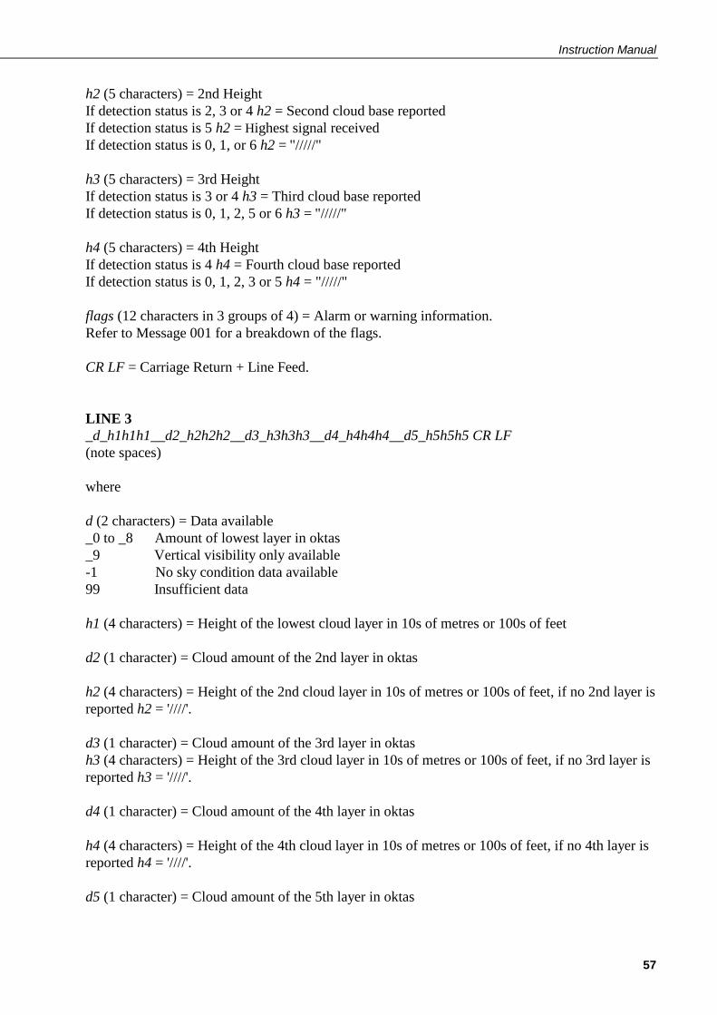
Instruction Manual
57
h2 (5 characters) = 2nd Height
If detection status is 2, 3 or 4 h2 = Second cloud base reported
If detection status is 5 h2 = Highest signal received
If detection status is 0, 1, or 6 h2 = "/////"
h3 (5 characters) = 3rd Height
If detection status is 3 or 4 h3 = Third cloud base reported
If detection status is 0, 1, 2, 5 or 6 h3 = "/////"
h4 (5 characters) = 4th Height
If detection status is 4 h4 = Fourth cloud base reported
If detection status is 0, 1, 2, 3 or 5 h4 = "/////"
flags (12 characters in 3 groups of 4) = Alarm or warning information.
Refer to Message 001 for a breakdown of the flags.
CR LF = Carriage Return + Line Feed.
LINE 3
_d_h1h1h1__d2_h2h2h2__d3_h3h3h3__d4_h4h4h4__d5_h5h5h5 CR LF
(note spaces)
where
d (2 characters) = Data available
_0 to _8 Amount of lowest layer in oktas
_9 Vertical visibility only available
-1 No sky condition data available
99 Insufficient data
h1 (4 characters) = Height of the lowest cloud layer in 10s of metres or 100s of feet
d2 (1 character) = Cloud amount of the 2nd layer in oktas
h2 (4 characters) = Height of the 2nd cloud layer in 10s of metres or 100s of feet, if no 2nd layer is
reported h2 = '////'.
d3 (1 character) = Cloud amount of the 3rd layer in oktas
h3 (4 characters) = Height of the 3rd cloud layer in 10s of metres or 100s of feet, if no 3rd layer is
reported h3 = '////'.
d4 (1 character) = Cloud amount of the 4th layer in oktas
h4 (4 characters) = Height of the 4th cloud layer in 10s of metres or 100s of feet, if no 4th layer is
reported h4 = '////'.
d5 (1 character) = Cloud amount of the 5th layer in oktas

CS135 Ceilometer
58
h5 (4 characters) = Height of the 5th cloud layer in 10s of metres or 100s of feet, if no 5th layer is
reported h5 = '////'.
CR LF= Carriage Return + Line Feed
Note cloud amounts and heights cannot be reported until the CS135 has been operating for 30
minutes.
LINE 4
scaleresn energylttrti_blpulseratesum CR LF
where
scale (5 characters) = Scale parameter,%, 0 ... 99999. 100% is default
res (2 characters) = Backscatter profile resolution in metres.
n (4 characters) = Profile length
energy (3 characters) = Laser pulse energy, %.
lt (3 characters including leading +/-) = Laser temperature, degrees C
ti (2 characters) = Total tilt angle, degrees
bl (4 characters) = Background light, millivolts at internal ADC input (0 ... 2500)
pulse (4 characters) = Pulse quantity x 1000 (0000-9999)
rate (2 characters) = Sample rate, MHz, (00-99)
sum = (3 characters) Sum of detected and normalized backscatter, 0 ... 999. Multiplied by scaling
factor times 104. At scaling factor 100 the SUM range 0 ... 999 corresponds to integrated
backscatter 0 ... 0. srad-1.
CR LF= Carriage Return + Line Feed
LINE 5
SSSSSSSSSSSSSSSSSSSSSSSSSSSSS........(2048 x 5 bytes) CR LF
The two-way attenuated normalised backscatter profile, see Section 2.1.4
CR LF= Carriage Return + Line Feed

Instruction Manual
59
LINE 6
ETX CRC-16 EOT CR LF
where
ETX = End-of-Text character
CRC-16 (4 characters) = CRC-16 Checksum
EOT= End-of-Transmission character
CR LF= Carriage Return + Line Feed

CS135 Ceilometer
60
MESSAGE 005 (no profile, sky condition, mixing layer heights)
Only available if a key is entered (see Section 5.1.11)
LINE 1
SOH CS ID OS N STX CR LF
where
SOH = Start-of-Heading character
CS = Always "CS"
ID (1 character) = A single ASCII character, 0-9, a - z or A - Z, case sensitive. Default ID = 0
OS (3 characters) = Operating system, 001 ... 999
N (3 characters) = Message number
STX = Start-of-Text Character
CR LF= Carriage Return + Line Feed
LINE 2
S WAtrh1h2h3h4flags CR LF
where
S (1 character) = detection status:
0 = No significant backscatter
1 = One cloud base detected
2 = Two cloud bases detected
3 = Three cloud bases detected
4 = Four cloud bases detected
5 = Full obscuration determined but no cloud base detected
6 = Some obscuration detected but determined to be transparent
/ = Raw data input to algorithm missing or suspect
WA (1 character) = Warning or alarm status:
0 = No alarm or warning
W = Warning
A = Alarm
tr (3 characters) = Window transmission, %
h1 (5 characters) = 1st Height
If detection status is 1, 2, 3 or 4 h1 = Lowest cloud base reported
If detection status is 5 h1 = Vertical visibility as calculated
If detection status is 0 or 6 h1 = "/////"
h2 (5 characters) = 2nd Height
If detection status is 2, 3 or 4 h2 = Second cloud base reported
If detection status is 5 h2 = Highest signal received
If detection status is 0, 1, 5 or 6 h2 = "/////"

Instruction Manual
61
h3 (5 characters) = 3rd Height
If detection status is 3 or 4 h3 = Third cloud base reported
If detection status is 0, 1, 2, 5 or 6 h3 = "/////"
h4 (5 characters) = 4th Height
If detection status is 4 h4 = Fourth cloud base reported
If detection status is 0, 1, 2, 3, 5 or 6 h4 = "/////"
flags (12 characters in 3 groups of 4) = Alarm or warning information.
Refer to Message 001 for a breakdown of the flags.
CR LF = Carriage Return and Line Feed
LINE 3
_d_h1__d2_h2__d3_h3__d4_h4__d5_h5 CR LF
(note spaces)
where
d (2 characters) = Data available
_0 to _8 Amount of lowest layer in oktas
_9 Vertical visibility only available
-1 No sky condition data available
99 Insufficient data
h1 (4 characters) = Height of the lowest cloud layer in 10s of metres or 100s of feet
d2 (1 character) = Cloud amount of the 2nd layer in oktas
h2 (4 characters) = Height of the 2nd cloud layer in 10s of metres or 100s of feet, if no 2nd layer is
reported h2 = '////'.
d3 (1 character) = Cloud amount of the 3rd layer in oktas
h3 (4 characters) = Height of the 3rd cloud layer in 10s of metres or 100s of feet, if no 3rd layer is
reported h3 = '////'.
d4 (1 character) = Cloud amount of the 4th layer in oktas
h4 (4 characters) = Height of the 4th cloud layer in 10s of metres or 100s of feet, if no 4th layer is
reported h4 = '////'.
d5 (1 character) = Cloud amount of the 5th layer in oktas
h5 (4 characters) = Height of the 5th cloud layer in 10s of metres or 100s of feet, if no 5th layer is
reported h5h = '////'.
CR LF= Carriage Return + Line Feed

CS135 Ceilometer
62
Note cloud amounts and heights cannot be reported until the CS135 has been operating for 30
minutes.
LINE 4
mh1_q1_mh2_q2_ mh3_q3
where
mh1 (5 characters) = height of the 1st MLH in metres
q1 (5 characters) = quality parameter of the 1st MLH
mh2 (5 characters) = height of the 2nd MLH in metres
q2 (5 characters) = quality parameter of the 2nd MLH
mh3 (5 characters) = height of the 3rd MLH in metres
q3 (5 characters) = quality parameter of the 3rd MLH
If there are no mixing layers detected, or less than 3, then missing data is shown as “/////”. If the
MLH option is not activated then all fields in line 4 are “/////”.
LINE 5
ETX CRC-16 EOT CR LF
where
ETX = End-of-Text character
CRC-16 (4 characters) = CRC-16 Checksum
EOT= End-of-Transmission character
CR LF= Carriage Return + Line Feed

Instruction Manual
63
MESSAGE 006 (profile, sky condition, mixing layer heights)
Only available if a key is entered (see Section 5.1.11)
LINE 1
SOH CS ID OS N STX CR LF
where
SOH = Start-of-Heading character
CS = Always "CS"
ID (1 character) = A single ASCII character, 0-9, a - z or A - Z, case sensitive. Default ID = 0
OS (3 characters) = Operating system, 001 ... 999
N (3 characters) = Message number
STX = Start-of-Text Character
CR LF= Carriage Return + Line Feed
LINE 2
S WAtrh1h2h3h4flags CR LF
where
S (1 character) = detection status:
0 = No significant backscatter
1 = One cloud base detected
2 = Two cloud bases detected
3 = Three cloud bases detected
4 = Four cloud bases detected
5 = Full obscuration determined but no cloud base detected
6 = Some obscuration detected but determined to be transparent
/ = Raw data input to algorithm missing or suspect
WA (1 character) = Warning or alarm status:
0 = No alarm or warning
W = Warning
A = Alarm
tr (3 characters) = Window transmission, %
h1 (5 characters) = 1st Height
If detection status is 1, 2, 3 or 4 h1 = Lowest cloud base reported
If detection status is 5 h1 = Vertical visibility as calculated
If detection status is 0 or 6 h1 = "/////"
h2 (5 characters) = 2nd Height
If detection status is 2, 3 or 4 h2 = Second cloud base reported

CS135 Ceilometer
64
If detection status is 5 h2 = Highest signal received
If detection status is 0, 1, 5 or 6 h2 = "/////"
h3 (5 characters) = 3rd Height
If detection status is 3 or 4 h3 = Third cloud base reported
If detection status is 0, 1, 2, 5 or 6 h3 = "/////"
h4 (5 characters) = 4th Height
If detection status is 4 h4 = Fourth cloud base reported
If detection status is 0, 1, 2, 3, 5 or 6 h4 = "/////"
flags (12 characters in 3 groups of 4) = Alarm or warning information.
Refer to Message 001 for a breakdown of the flags.
CR LF = Carriage Return and Line Feed
LINE 3
_d_h1__d2_h2__d3_h3__d4_h4__d5_h5 CR LF
(note spaces)
where
d (2 characters) = Data available
_0 to _8 Amount of lowest layer in oktas
_9 Vertical visibility only available
-1 No sky condition data available
99 Insufficient data
h1 (4 characters) = Height of the lowest cloud layer in 10s of metres or 100s of feet
d2 (1 character) = Cloud amount of the 2nd layer in oktas
h2 (4 characters) = Height of the 2nd cloud layer in 10s of metres or 100s of feet, if no 2nd layer is
reported h2 = '////'.
d3 (1 character) = Cloud amount of the 3rd layer in oktas
h3 (4 characters) = Height of the 3rd cloud layer in 10s of metres or 100s of feet, if no 3rd layer is
reported h3 = '////'.
d4 (1 character) = Cloud amount of the 4th layer in oktas
h4 (4 characters) = Height of the 4th cloud layer in 10s of metres or 100s of feet, if no 4th layer is
reported h4 = '////'.
d5 (1 character) = Cloud amount of the 5th layer in oktas

Instruction Manual
65
h5 (4 characters) = Height of the 5th cloud layer in 10s of metres or 100s of feet, if no 5th layer is
reported h5 = '////'.
CR LF= Carriage Return + Line Feed
Note cloud amounts and heights cannot be reported until the CS135 has been operating for 30
minutes.
LINE 4
scaleresnenergylttrtiblpulseratesum CR LF
where
scale (5 characters) = Scale parameter,%, 0 ... 99999. 100% is default
res (2 characters) = Backscatter profile resolution in metres.
n (4 characters) = Profile length
energy (3 characters) = Laser pulse energy, %.
lt (3 characters including leading +/-) = Laser temperature, degrees C
ti (2 characters) = Total tilt angle, degrees
bl (4 characters) = Background light, millivolts at internal ADC input (0 ... 2500)
pulse (4 characters) = Pulse quantity x 1000 (0000-9999)
rate (2 characters) = Sample rate, MHz, (00-99)
sum = (3 characters) Sum of detected and normalized backscatter, 0 ... 999. Multiplied by scaling
factor times 104. At scaling factor 100 the SUM range 0 ... 999 corresponds to integrated
backscatter 0 ... 0. srad-1
.
CR LF= Carriage Return + Line Feed
LINE 5
mh1_q1_mh2_q2_ mh3_q3
where
mh1 (5 characters) = height of the 1st MLH in metres
q1 (5 characters) = quality parameter of the 1st MLH
mh2 (5 characters) = height of the 2nd MLH in metres
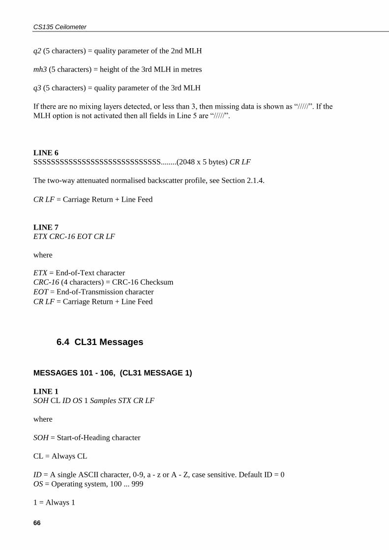
CS135 Ceilometer
66
q2 (5 characters) = quality parameter of the 2nd MLH
mh3 (5 characters) = height of the 3rd MLH in metres
q3 (5 characters) = quality parameter of the 3rd MLH
If there are no mixing layers detected, or less than 3, then missing data is shown as “/////”. If the
MLH option is not activated then all fields in Line 5 are “/////”.
LINE 6
SSSSSSSSSSSSSSSSSSSSSSSSSSSSS........(2048 x 5 bytes) CR LF
The two-way attenuated normalised backscatter profile, see Section 2.1.4.
CR LF= Carriage Return + Line Feed
LINE 7
ETX CRC-16 EOT CR LF
where
ETX = End-of-Text character
CRC-16 (4 characters) = CRC-16 Checksum
EOT= End-of-Transmission character
CR LF= Carriage Return + Line Feed
6.4 CL31 Messages
MESSAGES 101 - 106, (CL31 MESSAGE 1)
LINE 1
SOH CL ID OS 1 Samples STX CR LF
where
SOH = Start-of-Heading character
CL = Always CL
ID = A single ASCII character, 0-9, a - z or A - Z, case sensitive. Default ID = 0
OS = Operating system, 100 ... 999
1 = Always 1

Instruction Manual
67
Samples = backscatter resolution and number of samples
1 = MESSAGE 101, 10 m x 770 samples, range 7700 m
2 = MESSAGE 102, 20 m x 385 samples, range 7700 m
3 = MESSAGE 103, 5 m x 1500 samples, range 7500 m
4 = MESSAGE 104, 5 m x 770 samples, range 3850 m
5 = MESSAGE 105, no backscatter profile
0 = MESSAGE 106, extended range, 5 m x 2048 samples, range 10,240 m
STX = Start-of-Text Character
CR LF= Carriage Return + Line Feed
LINE 2
S WAh1h2h3flags CR LF
where
S (1 character) = detection status:
0 = No significant backscatter
1 = One cloud base detected
2 = Two cloud bases detected
3 = Three cloud bases detected
4 = Full obscuration determined but no cloud base detected
5 = Some obscuration detected but determined to be transparent
/ = Raw data input to algorithm missing or suspect
WA (1 character) = Warning or alarm status:
0 = No alarm or warning
W = Warning
A = Alarm
h1 (5 characters) = 1st Height
If detection status is 1, 2 or 3 h1 = Lowest cloud base reported
If detection status is 4 h1 = Vertical visibility as calculated
If detection status is 0 or 5 h1 = "/////"
h2 (5 characters) = 2nd Height
If detection status is 2 or 3 h2 = Second cloud base reported
If detection status is 4 h2 = Highest signal received
If detection status is 0, 1 or 5 h2 = "/////"
h3 (5 characters) = 3rd Height
If detection status is 3 h3 = Third cloud base reported
If detection status is 0, 1, 2, 4 or 5 h3 = "/////"
flags (12 characters) = Alarm or warning information.

CS135 Ceilometer
68
Description of the most significant alarm word (left word, bits going left to right)
Bit Description
8000 XXXX XXXX Transmitter shut-off
4000 XXXX XXXX Transmitter failure
2000 XXXX XXXX Receiver failure
1000 XXXX XXXX Reserved for future use
0800 XXXX XXXX Reserved for future use
0400 XXXX XXXX Memory error
0200 XXXX XXXX Light path obstruction
0100 XXXX XXXX Receiver saturation
0080 XXXX XXXX Reserved for future use
0040 XXXX XXXX Reserved for future use
0020 XXXX XXXX Reserved for future use
0010 XXXX XXXX Reserved for future use
0008 XXXX XXXX Reserved for future use
0004 XXXX XXXX Reserved for future use
0002 XXXX XXXX Reserved for future use
0001 XXXX XXXX Ceilometer engine board failure
Description of the middle alarm word (middle word, bits going left to right)
Bit Description
XXXX 8000 XXXX Window contamination
XXXX 4000 XXXX Battery voltage low
XXXX 2000 XXXX Transmitter expires
XXXX 1000 XXXX High humidity
XXXX 0800 XXXX Reserved for future use
XXXX 0400 XXXX Blower failure
XXXX 0200 XXXX Reserved for future use
XXXX 0100 XXXX Humidity sensor failure
XXXX 0080 XXXX Heater fault
XXXX 0040 XXXX High background radiance
XXXX 0020 XXXX Ceilometer engine board failure
XXXX 0010 XXXX Reserved for future use
XXXX 0008 XXXX Laser monitor failure
XXXX 0004 XXXX Receiver warning
XXXX 0002 XXXX Tilt beyond limit set by user, default 45 degrees
XXXX 0001 XXXX Reserved for future use
Description of the least significant alarm word (right word, bits going left to right)
Bit Description
XXXX XXXX 8000 Blower is on
XXXX XXXX 4000 Blower heater is on
XXXX XXXX 2000 Internal heater is on
XXXX XXXX 1000 Working from battery
XXXX XXXX 0800 Reserved for future use
XXXX XXXX 0400 Self test in progress
XXXX XXXX 0200 Reserved for future use
XXXX XXXX 0100 Reserved for future use
XXXX XXXX 0080 Units are metres if on, else feet
XXXX XXXX 0040 Reserved for future use
XXXX XXXX 0020 Polling mode is on
XXXX XXXX 0010 Reserved for future use
XXXX XXXX 0008 Reserved for future use
XXXX XXXX 0004 Reserved for future use
XXXX XXXX 0002 Reserved for future use
XXXX XXXX 0001 Reserved for future use

Instruction Manual
69
CR LF = Carriage Return + Line Feed
LINE 3
scaleresn energylttrti_blL0112HN15sum CR LF
where
scale (5 characters) = Scale parameter,%, 0 ... 99999. 100% is typical
res (2 characters) = Backscatter profile resolution in metres.
n (4 characters) = Profile length 385, 770, 1400, or 1500 samples.
energy (3 characters) = Laser pulse energy, %.
lt (3 characters including leading +/-) = Laser temperature, degrees C
tr (3 characters) = Window transmission, %
ti (2 characters) = Total tilt angle, degrees
bl (4 characters) = Background light, millivolts at internal ADC input (0 ... 2500)
"L0112HN15" (9 characters) = Reserved, defaults shown
sum = (3 characters) Sum of detected and normalized backscatter, 0 ... 999.
CR LF= Carriage Return + Line Feed
This line is omitted from message 105.
LINE 4
SSSSSSSSSSSSSSSSSSSSSSSSSSSSS........(5 x 770 bytes) CR LF
The two-way attenuated normalised backscatter profile, see Section 2.1.4.
CR LF= Carriage Return + Line Feed
This line is omitted from message 105.
NOTE
NOTE

CS135 Ceilometer
70
LINE 5
ETX CRC-16 EOT CR LF
where
ETX = End-of-Text character
CRC-16 (4 characters) = CRC-16 Checksum
EOT= End-of-Transmission character
CR LF= Carriage Return + Line Feed
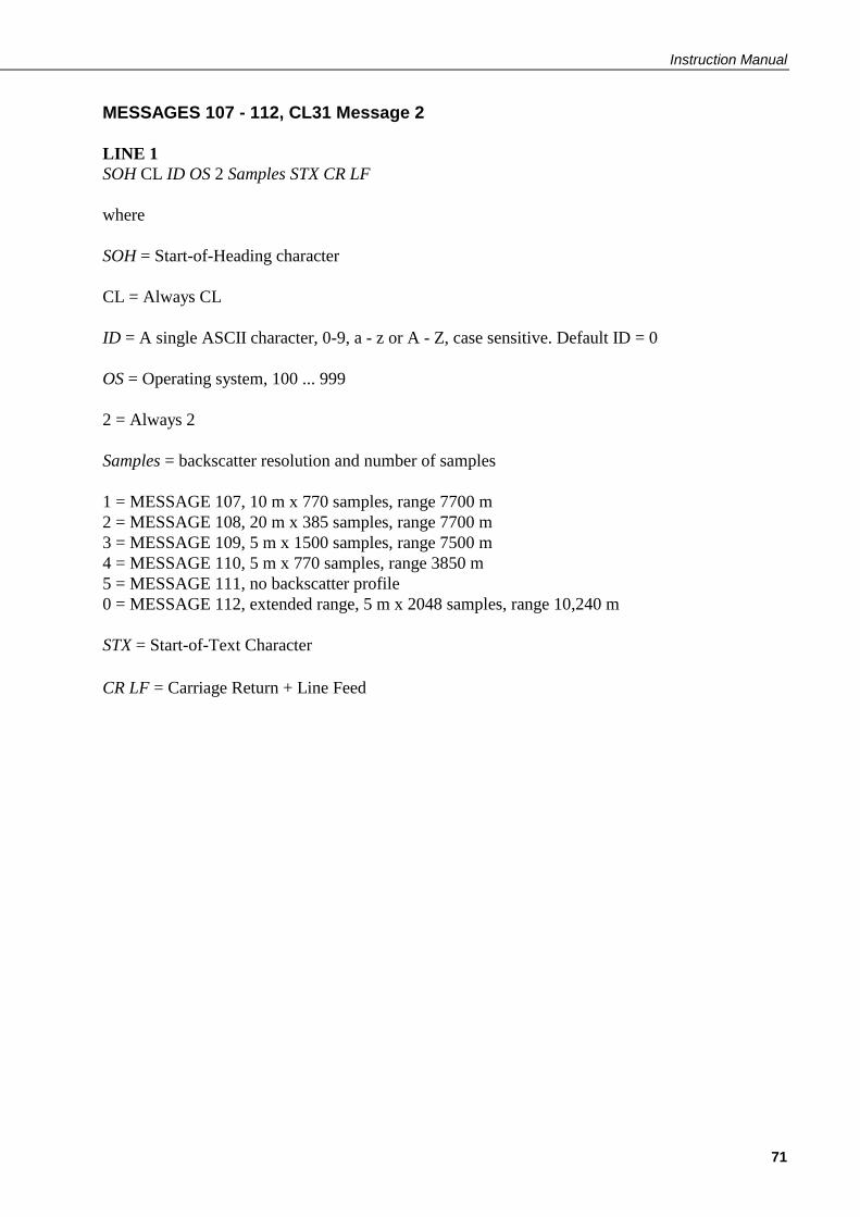
Instruction Manual
71
MESSAGES 107 - 112, CL31 Message 2
LINE 1
SOH CL ID OS 2 Samples STX CR LF
where
SOH = Start-of-Heading character
CL = Always CL
ID = A single ASCII character, 0-9, a - z or A - Z, case sensitive. Default ID = 0
OS = Operating system, 100 ... 999
2 = Always 2
Samples = backscatter resolution and number of samples
1 = MESSAGE 107, 10 m x 770 samples, range 7700 m
2 = MESSAGE 108, 20 m x 385 samples, range 7700 m
3 = MESSAGE 109, 5 m x 1500 samples, range 7500 m
4 = MESSAGE 110, 5 m x 770 samples, range 3850 m
5 = MESSAGE 111, no backscatter profile
0 = MESSAGE 112, extended range, 5 m x 2048 samples, range 10,240 m
STX = Start-of-Text Character
CR LF= Carriage Return + Line Feed

CS135 Ceilometer
72
LINE 2
S WAh1h2h3flags CR LF
where
S (1 character) = detection status:
0 = No significant backscatter
1 = One cloud base detected
2 = Two cloud bases detected
3 = Three cloud bases detected
4 = Full obscuration determined but no cloud base detected
5 = Some obscuration detected but determined to be transparent
/ = Raw data input to algorithm missing or suspect
WA (1 character) = Warning or alarm status:
0 = No alarm or warning
W = Warning
A = Alarm
h1 (5 characters) = 1st Height
If detection status is 1, 2 or 3 h1 = Lowest cloud base reported
If detection status is 4 h1 = Vertical visibility as calculated
If detection status is 0 or 5 h1 = "/////"
h2 (5 characters) = 2nd Height
If detection status is 2 or 3 h2 = Second cloud base reported
If detection status is 4 h2 = Highest signal received
If detection status is 0, 1 or 5 h2 = "/////"
h3 (5 characters) = 3rd Height
If detection status is 3 h3 = Third cloud base reported
If detection status is 0, 1, 2, 4 or 5 h3 = "/////"
flags (12 characters) = Alarm or warning information.
Same as for messages 101 – 106
CR LF = Carriage Return + Line Feed
LINE 3
__d_h1h1h1__d2_h2h2h2__d3_h3h3h3__d4_h4h4h4__d5_h5h5h5 CR LF
(note spaces)
where

Instruction Manual
73
d (1 character) = Data available
0 to 8 Amount of lowest layer in oktas
9 Vertical visibility only available
-1 No sky condition data available
99 Insufficient data
h1h1h1 (3 characters) = Height of the lowest cloud layer in 10s of metres or 100s of feet
d2 (1 character) = Cloud amount of the 2nd layer in oktas
h2h2h2 (3 characters) = Height of the 2nd cloud layer in 10s of metres or 100s of feet, if no 2nd
layer is reported h2h2h2 = '///'.
d3 (1 character) = Cloud amount of the 3rd layer in oktas
h3h3h3 (3 characters) = Height of the 3rd cloud layer in 10s of metres or 100s of feet, if no 3rd
layer is reported h3h3h3 = '///'.
d4 (1 character) = Cloud amount of the 4th layer in oktas
h4h4h4 (3 characters) = Height of the 4th cloud layer in 10s of metres or 100s of feet, if no 4th
layer is reported h4h4h4 = '///'.
d5 (1 character) = Cloud amount of the 5th layer in oktas
h5h5h5 (3 characters) = Height of the 5th cloud layer in 10s of metres or 100s of feet, if no 5th
layer is reported h5h5h5 = '///'.
CR LF= Carriage Return + Line Feed
Note cloud amount and height cannot be reported until the CS135 has been operating for 30
minutes.
LINE 4
scaleresn energylttrti_blL0112HN15sum CR LF
where
scale (5 characters) = Scale parameter,%, 0 ... 99999. 100% is typical
res (2 characters) = Backscatter profile resolution in metres.
n (4 characters) = Profile length 385, 770, 1400, or 1500 samples.
energy (3 characters) = Laser pulse energy, %.
lt (3 characters including leading +/-) = Laser temperature, degrees C
tr (3 characters) = Window transmission, %
CS135 Ceilometer
74
ti (2 characters) = Total tilt angle, degrees
bl (4 characters) = Background light, millivolts at internal ADC input (0 ... 2500)
"L0112HN15" (9 characters) = Reserved, defaults shown
sum = (3 characters) Sum of detected and normalized backscatter, 0 ... 999. Not used in Operating
System 1
CR LF= Carriage Return + Line Feed
This line is omitted from message 111.
LINE 5
SSSSSSSSSSSSSSSSSSSSSSSSSSSSS........(5 x 770 bytes) CR LF
The two-way attenuated normalised backscatter profile, see Section 2.1.4.
CR LF= Carriage Return + Line Feed
This line is omitted from message 111.
LINE 6
ETX CRC-16 EOT CR LF
ETX = End-of-Text Character
CRC-16 (4 characters) = CRC-16 Checksum
EOT = End-of-Transmission character
CR LF= Carriage Return + Line Feed
NOTE
NOTE

Instruction Manual
75
6.5 CT25K Messages
MESSAGE 113, CT25K Data Message No. 1
LINE 1
SOH CT ID 20 10 STX CR LF
where
SOH = Start-of-Heading character
CT = Always CT
ID (1 character) = Unit number 0 ... 9, A ... Z (capitals only) Default ID = 0
20 = Always `20’
10 = Always `10’
STX = Start-of-Text Character
CR LF= Carriage Return + Line Feed
LINE 2
S WAh1h2h3flags CR LF
where
S (1 character) = detection status:
0 = No significant backscatter
1 = One cloud base detected
2 = Two cloud bases detected
3 = Three cloud bases detected
4 = Full obscuration determined but no cloud base detected
5 = Some obscuration detected but determined to be transparent
/ = Raw data input to algorithm missing or suspect
WA (1 character) = Warning or alarm status:
0 = No alarm or warning
W = Warning
A = Alarm
h1 (5 characters) = 1st Height
If detection status is 1, 2 or 3 h1 = Lowest cloud base reported
If detection status is 4 h1 = Vertical visibility as calculated

CS135 Ceilometer
76
If detection status is 0 or 5 h1 = "/////"
h2 (5 characters) = 2nd Height
If detection status is 2 or 3 h2 = Second cloud base reported
If detection status is 4 h2 = Height of highest signal detected
If detection status is 0, 1 or 5 h2 = "/////"
h3 (5 characters) = 3rd Height
If detection status is 3 h3 = Third cloud base reported
If detection status is 0, 1, 2, 4 or 5 h3 = "/////"
flags (8 characters) = Alarm or warning information 4-byte hex coded
Description of the most significant alarm word (left side, bits going left to right). Each alarm
word is a hexadecimal sum of all the error bits.
Bit Description
8000 XXXX Transmitter shut-off
4000 XXXX Transmitter failure
2000 XXXX Receiver failure
1000 XXXX DSP, voltage or memory failure
0800 XXXX Reserved for future use
0400 XXXX Reserved for future use
0200 XXXX Reserved for future use
0100 XXXX Reserved for future use
0080 XXXX Window contaminated
0040 XXXX Battery low
0020 XXXX Transmitter expire warning
0010 XXXX Heater or humidity sensor failure
0008 XXXX High radiance warning, also XXXX 0004
0004 XXXX DSP, receiver, or laser monitor failure warning
0002 XXXX Relative humidity > 85 %
0001 XXXX Light path obstruction, receiver saturation or receiver failure
Description of the second alarm word (bits going left to right)
Bit Description
XXXX 8000 Blower failure
XXXX 4000 Reserved for future use
XXXX 2000 Reserved for future use
XXXX 1000 Reserved for future use
XXXX 0800 Blower on
XXXX 0400 Blower heater on
XXXX 0200 Internal heater on
XXXX 0100 Units metres if on, feet if off
XXXX 0080 Polling mode on
XXXX 0040 Working from battery
XXXX 0020 Always 0
XXXX 0010 Always 0
XXXX 0008 Tilt beyond limit set by user, default 45 degrees
XXXX 0004 High radiance warning, also 0008 XXXX
XXXX 0002 Reserved for future use
XXXX 0001 Reserved for future use
CR LF = Carriage Return + Line Feed

Instruction Manual
77
LINE 3
ETX CR LF
ETX = End-of-Text Character
CR LF= Carriage Return + Line Feed

CS135 Ceilometer
78
MESSAGE 114, CT25K Data Message No. 6
LINE 1
SOH CT ID 20 60 STX CR LF
where
SOH = Start-of-Heading character
CT = Always CT
ID (1 character) = Unit number 0 ... 9, A ... Z (capitals only) Default ID = 0
20 = always `20’
60 = always `60’
STX = Start-of-Text Character
CR LF= Carriage Return + Line Feed
LINE 2
S WAh1h2h3flags CR LF
where
S (1 character) = detection status:
0 = No significant backscatter
1 = One cloud base detected
2 = Two cloud bases detected
3 = Three cloud bases detected
4 = Full obscuration determined but no cloud base detected
5 = Some obscuration detected but determined to be transparent
/ = Raw data input to algorithm missing or suspect
WA (1 character) = Warning or alarm status:
0 = No alarm or warning
W = Warning
A = Alarm
h1 (5 characters) = 1st Height
If detection status is 1, 2 or 3 h1 = Lowest cloud base reported
If detection status is 4 h1 = Vertical visibility as calculated
If detection status is 0 or 5 h1 = "/////"
h2 (5 characters) = 2nd Height
If detection status is 2 or 3 h2 = Second cloud base reported

Instruction Manual
79
If detection status is 4 h2 = Height of highest signal detected
If detection status is 0, 1 or 5 h2 = "/////"
h3 (5 characters) = 3rd Height
If detection status is 3 h3 = Third cloud base reported
If detection status is 0, 1, 2, 4 or 5 h3 = "/////"
flags (8 characters) = Alarm or warning information 4-byte hex coded
As for CT25K message 1.
CR LF = Carriage Return + Line Feed
LINE 3 (SKY CONDITION)
__d_h1h1h1__d2_h2h2h2__d3_h3h3h3__d4_h4h4h4 CR LF
(note spaces)
where
d (1 character) = Data available
0 to 8 Amount of lowest layer in oktas
9 Vertical visibility only available
-1 No sky condition data available
99 Insufficient data
h1h1h1 (3 characters) = Height of the lowest cloud layer in 10s of metres or 100s of feet
d2 (1 character) = Cloud amount of the 2nd layer in oktas
h2h2h2 (3 characters) = Height of the 2nd cloud layer in 10s of metres or 100s of feet, if no 2nd
layer is reported h2h2h2 = '///'.
d3 (1 character) = Cloud amount of the 3rd layer in oktas
h3h3h3 (3 characters) = Height of the 3rd cloud layer in 10s of metres or 100s of feet, if no 3rd
layer is reported h3h3h3 = '///'.
d4 (1 character) = Cloud amount of the 4th layer in oktas
h4h4h4 (3 characters) = Height of the 4th cloud layer in 10s of metres or 100s of feet, if no 4th
layer is reported h4h4h4 = '///'.
CR LF= Carriage Return + Line Feed
Note cloud amount and height cannot be reported until the CS135 has been operating for 30
minutes.

CS135 Ceilometer
80
LINE 4
ETX CR LF
ETX = End-of-Text Character
CR LF= Carriage Return + Line Feed
7. Maintenance
7.1 General
The CS135 is a robust weather resistant instrument and there is no need for routine
maintenance other than cleaning. The instrument performance is monitored and
any potential problems are covered by error messages.
7.2 Cleaning
The CS135 window will require cleaning from time to time. The frequency of
required cleaning depends on the exposure of the instrument to contaminants such
as salt and dust. This will vary depending on the site location. The CS135 is
capable of self diagnosing dirty lenses and will indicate in its output when the
lenses are contaminated.
In any case we suggest six monthly intervals for locations not prone to
contaminants and monthly intervals for those prone to contamination (coastal,
roadside or airport use). In some cases more frequent cleaning may be required
where there are high levels of contaminants and high dependency on the
instrument output.
If the window requires cleaning, it is very important that only a proper lens cloth or lens tissue is used. The use of inappropriate materials to clean the windows can permanently damage or reduce their effectiveness leading to reduced performance.
CAUTION
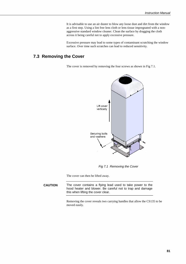
Instruction Manual
81
It is advisable to use an air duster to blow any loose dust and dirt from the window
as a first step. Using a lint free lens cloth or lens tissue impregnated with a non-
aggressive standard window cleaner. Clean the surface by dragging the cloth
across it being careful not to apply excessive pressure.
Excessive pressure may lead to some types of contaminant scratching the window
surface. Over time such scratches can lead to reduced sensitivity.
7.3 Removing the Cover
The cover is removed by removing the four screws as shown in Fig 7.1.
Fig 7.1 Removing the Cover
The cover can then be lifted away.
The cover contains a flying lead used to take power to the hood heater and blower. Be careful not to trap and damage this when lifting the cover clear.
Removing the cover reveals two carrying handles that allow the CS135 to be
moved easily.
CAUTION
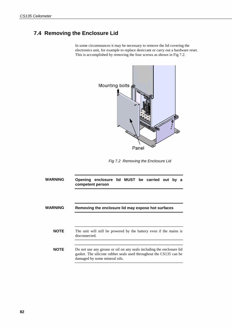
CS135 Ceilometer
82
7.4 Removing the Enclosure Lid
In some circumstances it may be necessary to remove the lid covering the
electronics unit, for example to replace desiccant or carry out a hardware reset.
This is accomplished by removing the four screws as shown in Fig 7.2.
Fig 7.2 Removing the Enclosure Lid
Opening enclosure lid MUST be carried out by a
competent person
Removing the enclosure lid may expose hot surfaces
The unit will still be powered by the battery even if the mains is
disconnected.
Do not use any grease or oil on any seals including the enclosure lid
gasket. The silicone rubber seals used throughout the CS135 can be
damaged by some mineral oils.
WARNING
WARNING
NOTE
NOTE

Instruction Manual
83
7.5 Diagnostic LED Indicators Within the Enclosure
Two green LEDs labelled "LASER ON" and "STATUS" are visible on the DSP
(see Fig 7.3). Their function is as follows:
"LASER ON" LED:
Off = laser off
Flashing = laser fault
On = laser on
"STATUS" LED
1 flash every 10 seconds = OK
2 flashes every 10 seconds = warning (possible degraded performance)
3 flashes every 10 seconds = alarm (measurements not possible)
The DSP "STATUS" LED duplicates the LED visible through the top window.
There is a red LED on the PSU. It will give 0.5 second flashes as follows:
1 flash every 10 seconds = PSU OK
2 flashes every 10 seconds = running in battery mode
3 flashes every 10 seconds = no communications to the DSP. This takes
60 seconds to start after a communications failure.
Fig 7.3 Diagnostic LED indicators
There is a red LED on the Laser module
Off = Laser off
On = Laser on

CS135 Ceilometer
84
7.6 Electrical Safety Testing
If carrying out insulation tests do not use voltages above 300V RMS
as the mains input has devices that effectively short circuit any
voltages above this level.
NOTE

A-1
Appendix A. Example CRBasic programs
A.1 Basic Logger program without CRC checking
'CR800 Series Datalogger
'Created by Sue Hill 18 July 2013
'CS135 Ceilometer connections
' Blue Tx C1
' White Rx C2
' Green G
'handshake lines shorted
SequentialMode
Const SOH = 1
Const STX = 2
Const ETX = 3
Const EOT = 4
Dim strInCS135 As String * 70
Dim Num_Bytes As Long
Dim strCS135_Message_Status As String * 1
Dim strCS135_Alarm_Status As String * 1
Dim CS135Lines(3) As String * 60
Dim CSLine2_Fields(7) As String * 20
Dim CS135_Unit_of_Measure As String * 3
Public strInformation As String * 100
Public strAlarm As String * 100
Public strError As String * 100
Alias CSLine2_Fields(1)=CS135_MessageAlarm_Status
Alias CSLine2_Fields(2)=CS135_Window_transmission
Alias CSLine2_Fields(3)=CS135_First_Height
Alias CSLine2_Fields(4)=CS135_Second_Height
Alias CSLine2_Fields(5)=CS135_Third_Height
Alias CSLine2_Fields(6)=CS135_Fourth_Height
Alias CSLine2_Fields(7)=CS135_Alarm_Flags
'Define Data Tables
DataTable(Ceilometer,True,-1)
DataInterval(0,15,sec,10)
Sample (1,strCS135_Message_Status,String)
Sample (1,strCS135_Alarm_Status,String)
Sample (1,CS135_First_Height, ieee4)
Sample (1,CS135_Second_Height, ieee4)
Sample (1,CS135_Third_Height, ieee4)
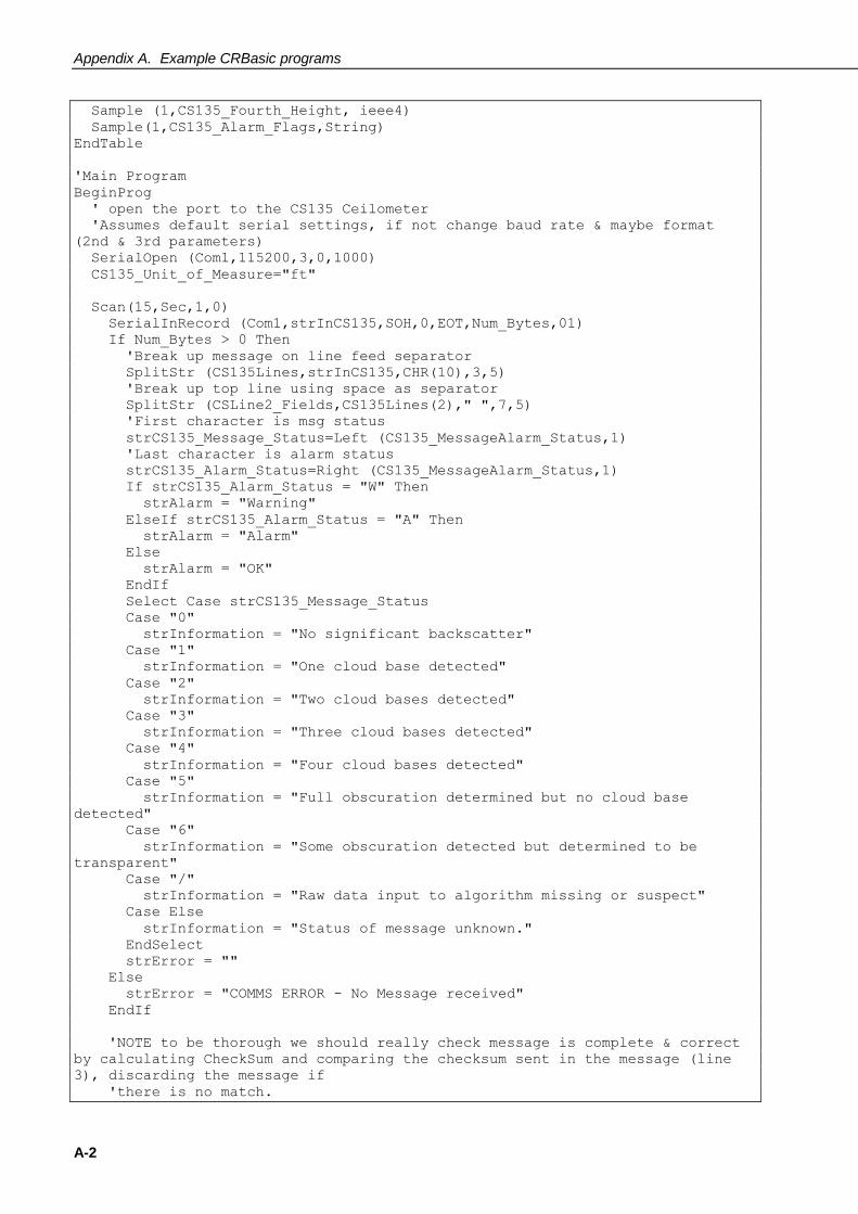
Appendix A. Example CRBasic programs
A-2
Sample (1,CS135_Fourth_Height, ieee4)
Sample(1,CS135_Alarm_Flags,String)
EndTable
'Main Program
BeginProg
' open the port to the CS135 Ceilometer
'Assumes default serial settings, if not change baud rate & maybe format
(2nd & 3rd parameters)
SerialOpen (Com1,115200,3,0,1000)
CS135_Unit_of_Measure="ft"
Scan(15,Sec,1,0)
SerialInRecord (Com1,strInCS135,SOH,0,EOT,Num_Bytes,01)
If Num_Bytes > 0 Then
'Break up message on line feed separator
SplitStr (CS135Lines,strInCS135,CHR(10),3,5)
'Break up top line using space as separator
SplitStr (CSLine2_Fields,CS135Lines(2)," ",7,5)
'First character is msg status
strCS135_Message_Status=Left (CS135_MessageAlarm_Status,1)
'Last character is alarm status
strCS135_Alarm_Status=Right (CS135_MessageAlarm_Status,1)
If strCS135_Alarm_Status = "W" Then
strAlarm = "Warning"
ElseIf strCS135_Alarm_Status = "A" Then
strAlarm = "Alarm"
Else
strAlarm = "OK"
EndIf
Select Case strCS135_Message_Status
Case "0"
strInformation = "No significant backscatter"
Case "1"
strInformation = "One cloud base detected"
Case "2"
strInformation = "Two cloud bases detected"
Case "3"
strInformation = "Three cloud bases detected"
Case "4"
strInformation = "Four cloud bases detected"
Case "5"
strInformation = "Full obscuration determined but no cloud base
detected"
Case "6"
strInformation = "Some obscuration detected but determined to be
transparent"
Case "/"
strInformation = "Raw data input to algorithm missing or suspect"
Case Else
strInformation = "Status of message unknown."
EndSelect
strError = ""
Else
strError = "COMMS ERROR - No Message received"
EndIf
'NOTE to be thorough we should really check message is complete & correct
by calculating CheckSum and comparing the checksum sent in the message (line
3), discarding the message if
'there is no match.

Appendix A. Example CRBasic programs
A-3
CallTable(Ceilometer)
NextScan
EndProg
A.2 Basic Logger program with CRC checking
'CR800 Series Datalogger
'Created by Sue Hill 18 July 2013
'CS135 Ceilometer connections
' Blue Tx C1
' White Rx C2
' Green G
'handshake lines shorted
SequentialMode
Const SOH = 1
Const STX = 2
Const ETX = 3
Const EOT = 4
Dim strInCS135 As String * 70
Dim Num_Bytes As Long
Dim strCS135_Message_Status As String * 1
Dim strCS135_Alarm_Status As String * 1
Dim lngCRCCalc As Long
Dim lngCRCMessage As Long
Dim DataOK As Boolean
Dim CS135Lines(3) As String * 60
Dim CSLine2_Fields(7) As String * 20
Dim CS135_Unit_of_Measure As String * 3
Public strInformation As String * 100
Public strAlarm As String * 100
Public strError As String * 100
Alias CSLine2_Fields(1)=CS135_MessageAlarm_Status
Alias CSLine2_Fields(2)=CS135_Window_transmission
Alias CSLine2_Fields(3)=CS135_First_Height
Alias CSLine2_Fields(4)=CS135_Second_Height
Alias CSLine2_Fields(5)=CS135_Third_Height
Alias CSLine2_Fields(6)=CS135_Fourth_Height
Alias CSLine2_Fields(7)=CS135_Alarm_Flags
'Define Data Tables
DataTable(Ceilometer,True,-1)
DataInterval(0,15,sec,10)
Sample (1,strCS135_Message_Status,String)
Sample (1,strCS135_Alarm_Status,String)
Sample (1,CS135_First_Height, ieee4)

Appendix A. Example CRBasic programs
A-4
Sample (1,CS135_Second_Height, ieee4)
Sample (1,CS135_Third_Height, ieee4)
Sample (1,CS135_Fourth_Height, ieee4)
Sample(1,CS135_Alarm_Flags,String)
EndTable
'Main Program
BeginProg
' open the port to the CS135 Ceilometer
'Assumes default serial settings, if not change baud rate & maybe format
(2nd & 3rd parameters)
SerialOpen (Com1,115200,3,0,1000)
CS135_Unit_of_Measure="ft"
Scan(15,Sec,1,0)
SerialInRecord (Com1,strInCS135,SOH,0,EOT,Num_Bytes,01)
If Num_Bytes > 0 Then
'Break up message on line feed separator
SplitStr (CS135Lines,strInCS135,CHR(10),3,5)
'Break up top line using space as separator
SplitStr (CSLine2_Fields,CS135Lines(2)," ",7,5)
'First character is msg status
strCS135_Message_Status=Left (CS135_MessageAlarm_Status,1)
'Last character is alarm status
strCS135_Alarm_Status=Right (CS135_MessageAlarm_Status,1)
If strCS135_Alarm_Status = "W" Then
strAlarm = "Warning"
ElseIf strCS135_Alarm_Status = "A" Then
strAlarm = "Alarm"
Else
strAlarm = "OK"
EndIf
Select Case strCS135_Message_Status
Case "0"
strInformation = "No significant backscatter"
Case "1"
strInformation = "One cloud base detected"
Case "2"
strInformation = "Two cloud bases detected"
Case "3"
strInformation = "Three cloud bases detected"
Case "4"
strInformation = "Four cloud bases detected"
Case "5"
strInformation = "Full obscuration determined but no cloud base
detected"
Case "6"
strInformation = "Some obscuration detected but determined to be
transparent"
Case "/"
strInformation = "Raw data input to algorithm missing or suspect"
Case Else
strInformation = "Status of message unknown."
EndSelect
'Make sure message is complete & correct
lngCRCCalc = CheckSum (Left(strInCS135,Num_Bytes-4),18,0) XOR &HFFFF
lngCRCMessage = HexToDec (Mid(strInCS135,59,4))
DataOK = (Num_Bytes = 62) AND (lngCRCCalc = lngCRCMessage)
If NOT DataOK Then
strError = "Data error, messages may be incomplete!"
Else

Appendix A. Example CRBasic programs
A-5
strError = ""
EndIf
Else
strError = "COMMS ERROR - No Message received"
EndIf
CallTable(Ceilometer)
NextScan
EndProg

Appendix A. Example CRBasic programs
A-6
B-1
Appendix B. Measurement of the attenuated backscatter profile
B.1 Initial measurement
Pulse the laser and measure the backscatter at optimal gains.
Derive the impulse response and impulse correct the backscatter signal
using the inverse filter derived.
Remove the residual offset and slope from the impulse corrected
backscatter.
Apply an overlap correction based on the known generic overlap function
of the CS135.
Apply the backscatter calibration constants.
Remove the laser and electronic artefact signature. This is specific to the
individual CS135 and determined during calibration.
B.2 Backscatter onset height detection Filter the backscatter with 20 m and 300 m width filters.
Look for a 1500 m block width where the standard deviation is at a
minimum for both the 20 m and 300 m width filtered backscatters.
Create a detection threshold by multiplying the 20 m and 300 m standard
deviations by a constant.
Find the onset of backscatter height by working from the highest height
bin downwards until the backscatter is above one or both of the two
detection thresholds.
B.3 Produce attenuated backscatter output message Range correct the backscatter to produce the attenuated backscatter.
Attenuated backscatter (output), calibrated, range corrected but not tilt
corrected.
Smooth with a 20 m width running average.
A noise gate can be applied based on a multiple of the 20 m detection
threshold – this is customer configurable.
Note the lower height range bins do not gate noise until the backscatter
reaches zero. This allows the full extent of mixing layers to be viewed in
gating mode.

Appendix B. Measurement of the attenuated backscatter profile
B-2

C-1
Appendix C. Cloud height calculation
The scatter profile is inverted (using the Klett inversion technique) and an
extinction profile is calculated.
Cloud base heights are identified using two criteria as follows (cloud is detected if
either of them is met:
Criterion 1: likely cloud bases are estimated based on increasing slope of the
extinction profile of at least 7 m per bin (bin width is 5 m) and an extinction
threshold. This threshold is based on an extinction coefficient (EXCO) of 3,
equivalent to a horizontal visibility (MOR) of 1,000 m. This results in a number of
possible cloud bases at different heights.
Criterion 2: horizontal visibility falls below an average of 4,800 m over 300 m
starting at an altitude of 1000 m.
To report a cloud layer above a lower one the scatter coefficient first has to fall
below the extinction threshold used for cloud definitions (less a small hysteresis
offset). The scatter profile must then again meet the criteria above.
If rain is detected the sensitivity of detection is increased by a factor of 3.
To avoid many very narrow close layers being reported when they have little
significance a minimum separation based on WMO reporting intervals is applied.
The separation is +/- 30 m below 1,500 m and 300 m above 1,500 m. The lowest
cloud height is used. If a thin cloud identified by Criterion 2 above is within
+/-150 m of a cloud identified by criterion 1 then the thin cloud is ignored.

Appendix C. Cloud height calculation
C-2

D-1
Appendix D. Sky condition algorithm description
The CS135 sky condition algorithm follows guidance from ICAO and WMO
documents* and is based on 30 minutes of data. For this reason sky condition is
not available for 30 minutes after power cycling the sensor, a reboot or changing
measurement parameters. The sky condition algorithm is as follows:
Each measured hit comprising the lowest cloud height, (vertical visibility + onset
of backscatter) / 2 and a weighting of 1 or 2 is stored in a running half hour buffer.
The weighting is 2 for hits in the last 10 minutes and 1 for hits in the previous 20
minutes.
If >50% of the hits in the latest 10 minutes are vertical visibility then the vertical visibility averaged over the last 10 minutes is reported. Only hits below the
vertical visibility height limit set are used.
The buffer is sorted in height order and hits combined into bins with the following
widths.
Height Bin width
0 - 5,000 ft 100 ft
5,000 – 15,000 ft 200 ft
15,000 ft – 33,000 ft 500 ft
For each bin a mean height is calculated by the following:
Hi = ∑(hiwi)/∑(wi)
Where wi is the weight (1 or 2) of the hit with height hi
Bins are then reduced. A distance (D) between adjacent bins is calculated by the
following equation:
D = NiNj (Hi-Hj)2/Ni+Nj
Where Ni and Nj are the sum of hits of each bin and Hi and Hj the respective
heights.
Find the pair with the minimum distance D and combine into one bin with the
height of the lowest and number of hits of the combined total.
This process is repeated until 5 or less bins remain. These are now taken as cloud
layers.
Finally if cloud layers are closer than the distances below then they are merged
with the height of the lowest and combined total number of hits.

Appendix D. Sky condition algorithm description
D-2
Height range Distance (D)
Height ≤ 300 m (1,000 ft) ≤ 90 m (300 ft)
300 m < Height ≤ 900 m (1,000 ft
< Height ≤ 3,000 ft)
≤ 120 m (400 ft)
900 m < Height ≤ 1,500 m (3,000 ft
< Height ≤ 5,000 ft)
≤ 180 m (600 ft)
1,500 m < Height ≤ 2,400 m (5,000 ft < Height ≤ 8,000 ft)
≤ 300 m (1,000 ft)
Height > 2,400 m (8,000 ft) ≤ 480 m (1,600 ft)
Weights per layer are used to calculate number of oktas per layer.
If the total possible is Wmax then the cover is (Wi/Wmax) x 8.
Cloud amounts are rounded up to the next highest whole oktas.
For layers above the lowest this is based on the maximum possible weights. If the
lower layers have W1 hits and the next layer has W2 hits then the cover of the
higher layer is given by:
(W2/(Wmax-W1)) x 8
For example, taking weighting into account, if lower layers of cloud only allow
4/8 of clear sky above and the cover is 2/8 out of those 4/8 then the layer above is
taken as 4/8.
Finally only layers meeting the following criteria are reported:
Layer 1 ≥ 1/33 oktas
Layer 2 ≥ 3 oktas
Layer 3 ≥ 5 oktas
Layer 4 ≥ 7 oktas
Layer 5 ≥ 7 oktas
Any layer > (8 – 1/33) oktas is reported as 8 oktas
*ICAO 9837 Manual on Automatic Meteorological Observing Systems at
Aerodromes.
WMO – No. 306 Manual on Codes


CAMPBELL SCIENTIFIC COMPANIES
Campbell Scientific, Inc. (CSI) 815 West 1800 North Logan, Utah 84321 UNITED STATES
www.campbellsci.com [email protected]
Campbell Scientific Africa Pty. Ltd. (CSAf) PO Box 2450
Somerset West 7129 SOUTH AFRICA
www.csafrica.co.za [email protected]
Campbell Scientific Southeast Asia Co., Ltd. 877/22 Nirvana@Work, Rama 9 Road
Suan Luang Subdistrict, Suan Luang District Bangkok 10250
THAILAND www.campbellsci.asia [email protected]
Campbell Scientific Australia Pty. Ltd. (CSA) PO Box 8108
Garbutt Post Shop QLD 4814 AUSTRALIA
www.campbellsci.com.au [email protected]
Campbell Scientific do Brazil Ltda. (CSB) Rua Apinagés, nbr. 2018 - Perdizes
CEP: 01258-00 São Paulo SP BRAZIL www.campbellsci.com.br [email protected]
Campbell Scientific Canada Corp. (CSC) 14532 – 131 Avenue NW
Edmonton, Alberta T5L 4X4 CANADA
www.campbellsci.ca [email protected]
Campbell Scientific Centro Caribe S.A. (CSCC) 300N Cementerio, Edificio Breller
Santo Domingo, Heredia 40305 COSTA RICA
www.campbellsci.cc [email protected]
Campbell Scientific Ltd. (CSL) 80 Hathern Road, Shepshed, Loughborough LE12 9GX
UNITED KINGDOM www.campbellsci.co.uk [email protected]
Campbell Scientific Ltd. (France) 3 Avenue de la Division Leclerc
92160 ANTONY FRANCE
www.campbellsci.fr [email protected]
Campbell Scientific Spain, S. L. Avda. Pompeu Fabra 7-9
Local 1 - 08024 BARCELONA SPAIN
www.campbellsci.es [email protected]
Campbell Scientific Ltd. (Germany) Fahrenheitstrasse13, D-28359 Bremen
GERMANY www.campbellsci.de [email protected]
Campbell Scientific (Beijing) Co., Ltd. 8B16, Floor 8 Tower B, Hanwei Plaza
7 Guanghua Road, Chaoyang, Beijing 100004 P.R. CHINA
www.campbellsci.com [email protected]
Please visit www.campbellsci.eu to obtain contact information for your local EU or International representative.