cs3516-14-networklayer - worcester polytechnic institute · some slides are originally from the...
TRANSCRIPT
1
CS 3516: Advanced Computer Networks
Prof. Yanhua Li
Welcome to
Time: 9:00am –9:50am M, T, R, and F Location: Fuller 320 Fall 2016 A-term
Some slides are originally from the course materials of the textbook “Computer Networking: A Top Down Approach”, 6th edition, by
Jim Kurose, Keith Ross, Addison-Wesley March 2012. Copyright 1996-2013 J.F Kurose and K.W. Ross, All Rights Reserved.

Network Layer 4-2
Quiz 6 on Thursday
Network Layer 4-3
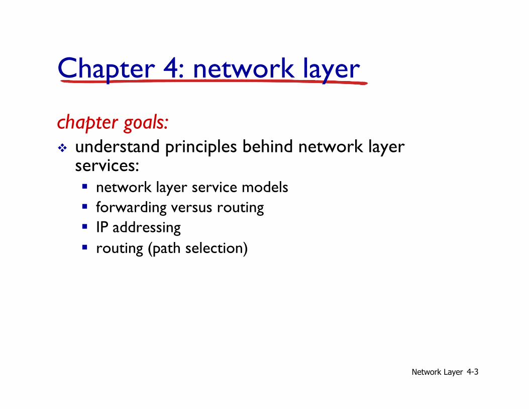
Chapter 4: network layer
chapter goals: v understand principles behind network layer
services: § network layer service models § forwarding versus routing § IP addressing § routing (path selection)

Network Layer 4-4
4.1 introduction 4.4 IP: Internet Protocol
§ datagram format § IPv4 addressing
Chapter 4: outline

Network Layer 4-5
Network layer v transport segment from
sending to receiving host v on sending side
encapsulates segments into datagrams
v on receiving side, delivers segments to transport layer
v network layer protocols in every host, router
v router examines header fields in all IP datagrams passing through it
application transport network data link physical
application transport network data link physical
network data link physical
network data link physical
network data link physical
network data link physical
network data link physical
network data link physical
network data link physical
network data link physical
network data link physical
network data link physical
network data link physical
Network Layer 4-6
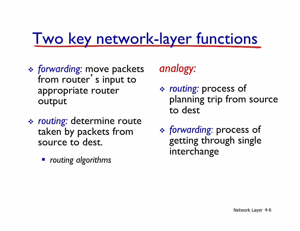
Two key network-layer functions
v forwarding: move packets from router’s input to appropriate router output
v routing: determine route taken by packets from source to dest.
§ routing algorithms
analogy:
v routing: process of planning trip from source to dest
v forwarding: process of getting through single interchange
Network Layer 4-7
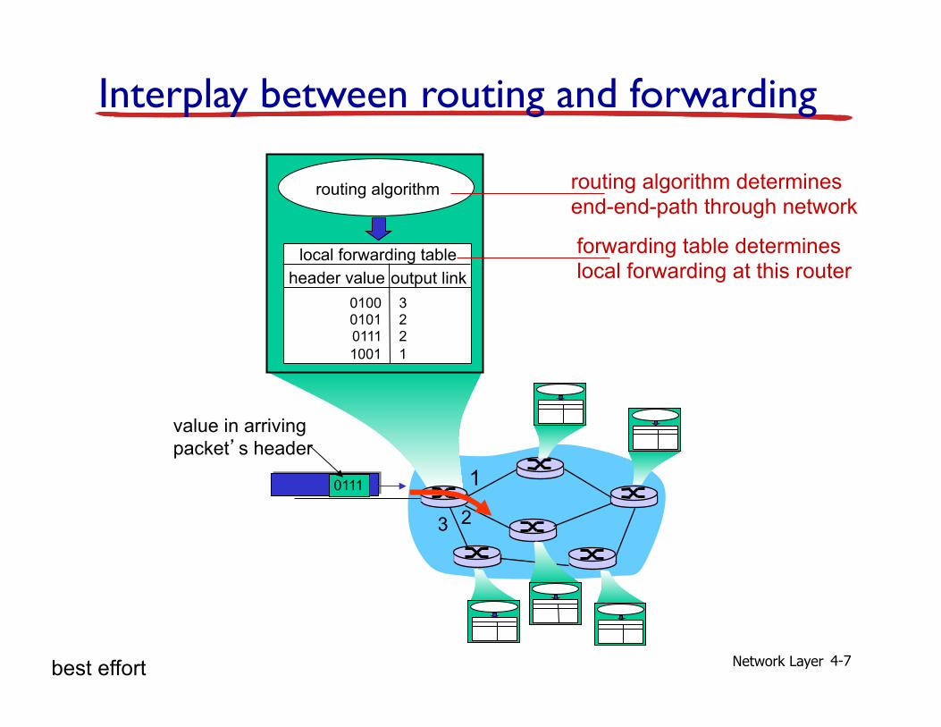
1
2 3
0111
value in arriving packet’s header
routing algorithm
local forwarding table header value output link
0100 0101 0111 1001
3 2 2 1
Interplay between routing and forwarding
routing algorithm determines end-end-path through network
forwarding table determines local forwarding at this router
best effort
Network Layer 4-8
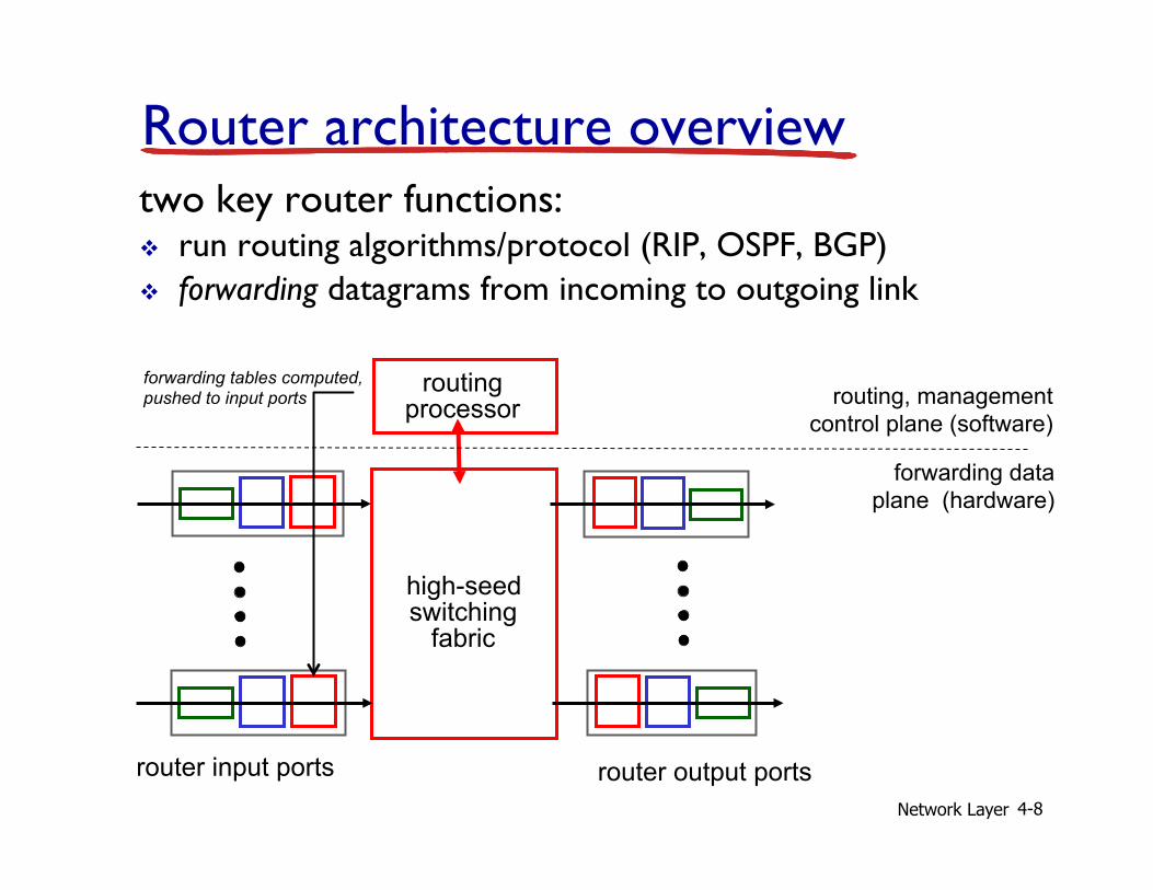
Router architecture overview two key router functions: v run routing algorithms/protocol (RIP, OSPF, BGP) v forwarding datagrams from incoming to outgoing link
high-seed switching
fabric
routing processor
router input ports router output ports
forwarding data plane (hardware)
routing, management control plane (software)
forwarding tables computed, pushed to input ports

Network Layer 4-9
Destination Address Range 11001000 00010111 00010000 00000000 through 11001000 00010111 00010111 11111111 11001000 00010111 00011000 00000000 through 11001000 00010111 00011000 11111111 11001000 00010111 00011001 00000000 through 11001000 00010111 00011111 11111111 otherwise
Link Interface 0 1 2 3
Q: but what happens if ranges don’t divide up so nicely?
Datagram forwarding table
Network Layer 4-10
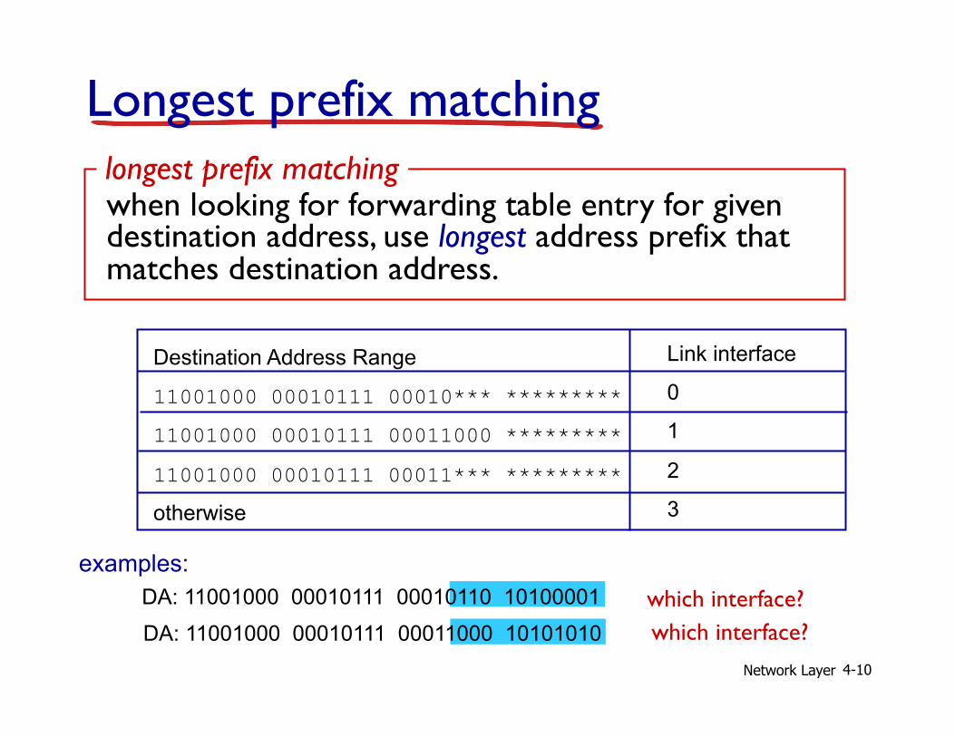
Longest prefix matching
Destination Address Range
11001000 00010111 00010*** *********
11001000 00010111 00011000 *********
11001000 00010111 00011*** ********* otherwise
DA: 11001000 00010111 00011000 10101010
examples: DA: 11001000 00010111 00010110 10100001 which interface?
which interface?
when looking for forwarding table entry for given destination address, use longest address prefix that matches destination address.
longest prefix matching
Link interface
0
1
2
3

Network Layer 4-11
4.1 introduction 4.4 IP: Internet Protocol
§ datagram format § IPv4 addressing
Chapter 4: outline

Network Layer 4-12
The Internet network layer
forwarding table
host, router network layer functions:
routing protocols • path selection • RIP, OSPF, BGP
IP protocol • addressing conventions • datagram format • packet handling conventions
ICMP protocol • error reporting • router “signaling”
transport layer: TCP, UDP
link layer
physical layer
network layer
Network Layer 4-13
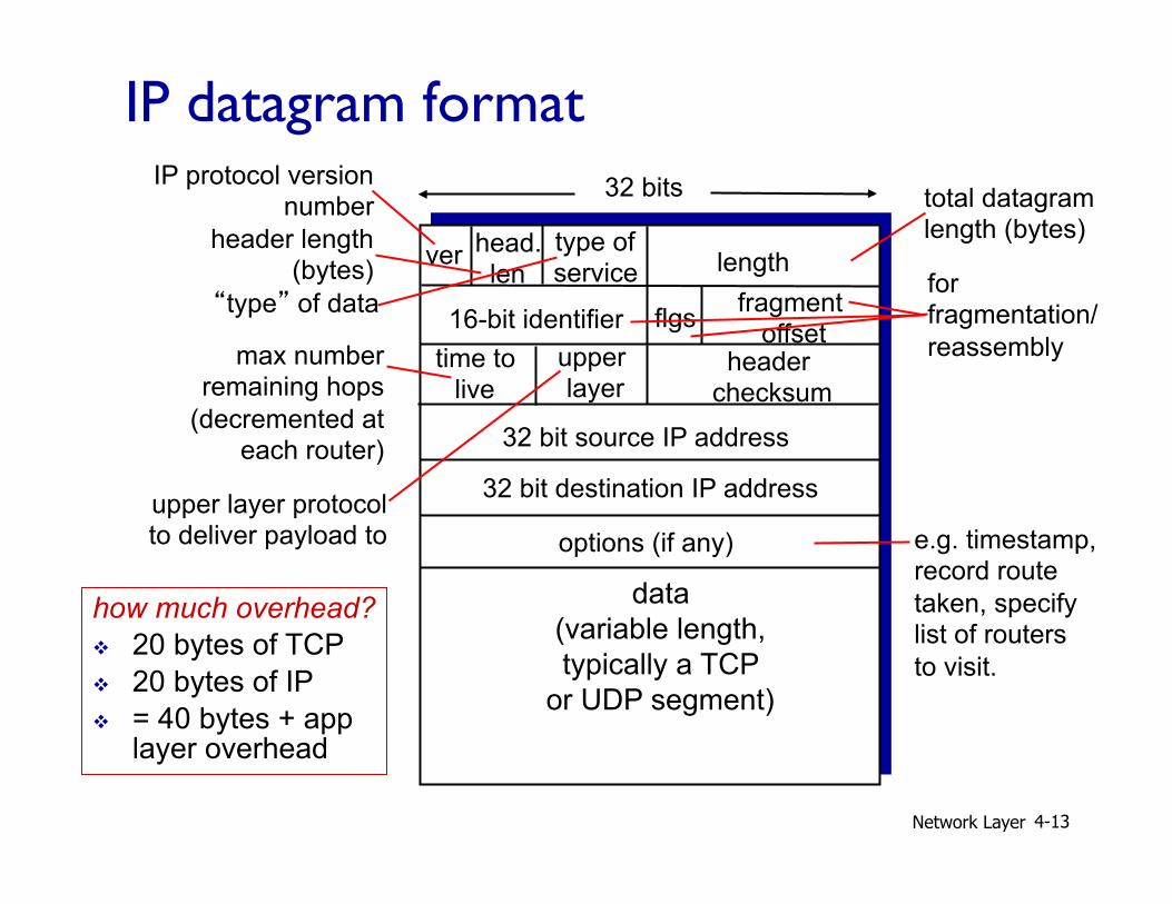
ver length
32 bits
data (variable length, typically a TCP
or UDP segment)
16-bit identifier header
checksum time to
live
32 bit source IP address
head. len
type of service
flgs fragment offset
upper layer
32 bit destination IP address options (if any)
IP datagram format IP protocol version
number
header length (bytes)
upper layer protocol to deliver payload to
total datagram length (bytes)
“type” of data for fragmentation/ reassembly max number
remaining hops (decremented at
each router)
e.g. timestamp, record route taken, specify list of routers to visit.
how much overhead? v 20 bytes of TCP v 20 bytes of IP v = 40 bytes + app
layer overhead
Network Layer 4-14
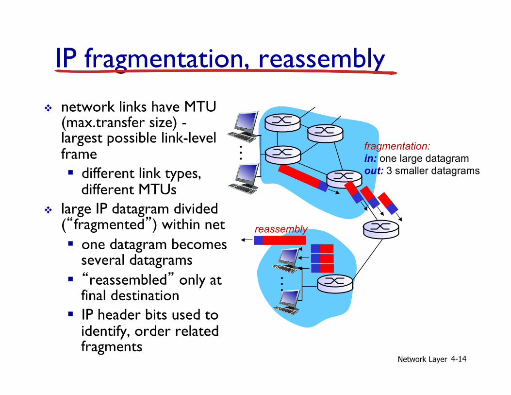
IP fragmentation, reassembly v network links have MTU
(max.transfer size) - largest possible link-level frame § different link types,
different MTUs v large IP datagram divided
(“fragmented”) within net § one datagram becomes
several datagrams § “reassembled” only at
final destination § IP header bits used to
identify, order related fragments
fragmentation: in: one large datagram out: 3 smaller datagrams
reassembly
…
…
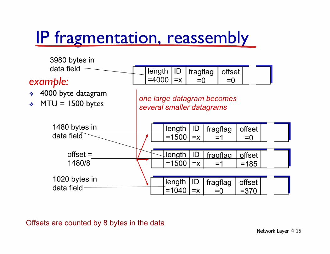
Network Layer 4-15
ID =x
offset =0
fragflag =0
length =4000
ID =x
offset =0
fragflag =1
length =1500
ID =x
offset =185
fragflag =1
length =1500
ID =x
offset =370
fragflag =0
length =1040
one large datagram becomes several smaller datagrams
example: v 4000 byte datagram v MTU = 1500 bytes
1480 bytes in data field
offset = 1480/8
IP fragmentation, reassembly
1020 bytes in data field
3980 bytes in data field
Offsets are counted by 8 bytes in the data
Network Layer 4-16
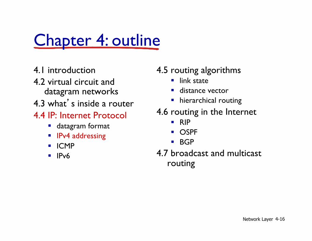
4.1 introduction 4.2 virtual circuit and
datagram networks 4.3 what’s inside a router 4.4 IP: Internet Protocol
§ datagram format § IPv4 addressing § ICMP § IPv6
4.5 routing algorithms § link state § distance vector § hierarchical routing
4.6 routing in the Internet § RIP § OSPF § BGP
4.7 broadcast and multicast routing
Chapter 4: outline
Network Layer 4-17
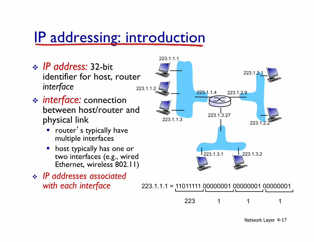
IP addressing: introduction
v IP address: 32-bit identifier for host, router interface
v interface: connection between host/router and physical link § router’s typically have
multiple interfaces § host typically has one or
two interfaces (e.g., wired Ethernet, wireless 802.11)
v IP addresses associated with each interface
223.1.1.1
223.1.1.2
223.1.1.3
223.1.1.4 223.1.2.9
223.1.2.2
223.1.2.1
223.1.3.2 223.1.3.1
223.1.3.27
223.1.1.1 = 11011111 00000001 00000001 00000001
223 1 1 1

Network Layer 4-18
IP addressing: introduction
Q: how are interfaces actually connected? A: we’ll learn about that in chapter 5, 6.
223.1.1.1
223.1.1.2
223.1.1.3
223.1.1.4 223.1.2.9
223.1.2.2
223.1.2.1
223.1.3.2 223.1.3.1
223.1.3.27
A: wired Ethernet interfaces connected by Ethernet switches
A: wireless WiFi interfaces connected by WiFi base station
For now: don’t need to worry about how one interface is connected to another (with no intervening router)

Network Layer 4-19
Subnets
v IP address: § subnet part - high order bits
§ host part - low order bits
v what’s a subnet ? § device interfaces with same subnet part of IP address
§ can physically reach each other without intervening router network consisting of 3 subnets
223.1.1.1
223.1.1.3
223.1.1.4 223.1.2.9
223.1.3.2 223.1.3.1
subnet
223.1.1.2
223.1.3.27 223.1.2.2
223.1.2.1
Network Layer 4-20
recipe v to determine the
subnets, detach each interface from its host or router, creating islands of isolated networks
v each isolated network is called a subnet
subnet mask: /24
Subnets 223.1.1.0/24
223.1.2.0/24
223.1.3.0/24
223.1.1.1
223.1.1.3
223.1.1.4 223.1.2.9
223.1.3.2 223.1.3.1
subnet
223.1.1.2
223.1.3.27 223.1.2.2
223.1.2.1
Network Layer 4-21
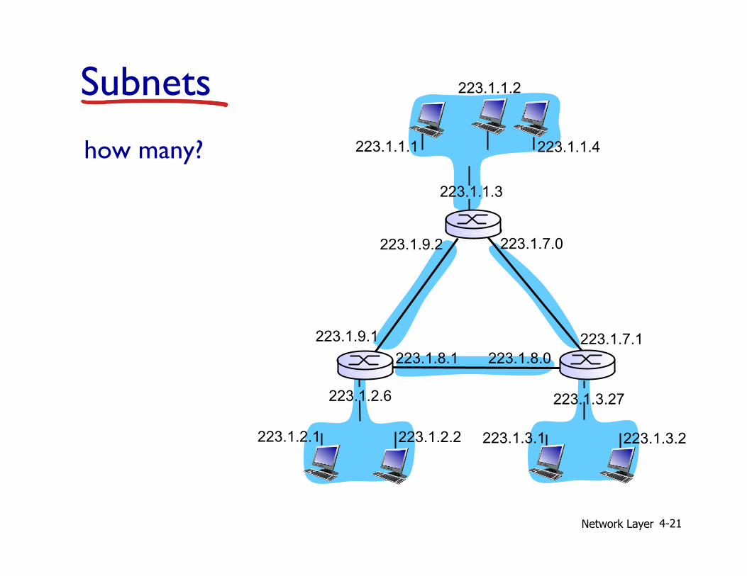
how many? 223.1.1.1
223.1.1.3
223.1.1.4
223.1.2.2 223.1.2.1
223.1.2.6
223.1.3.2 223.1.3.1
223.1.3.27
223.1.1.2
223.1.7.0
223.1.7.1 223.1.8.0 223.1.8.1
223.1.9.1
223.1.9.2
Subnets
Network Layer 4-22
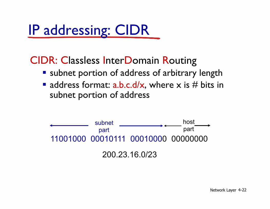
IP addressing: CIDR
CIDR: Classless InterDomain Routing § subnet portion of address of arbitrary length § address format: a.b.c.d/x, where x is # bits in
subnet portion of address
11001000 00010111 00010000 00000000
subnet part
host part
200.23.16.0/23
Network Layer 4-23
IP addresses: how to get one? Q: How does a host get IP address? v hard-coded by system admin in a file
§ Windows: control-panel->network->configuration->tcp/ip->properties
§ UNIX: /etc/rc.config v DHCP: Dynamic Host Configuration Protocol:
dynamically get address from as server § “plug-and-play”
Network Layer 4-24
DHCP: Dynamic Host Configuration Protocol
goal: allow host to dynamically obtain its IP address from network server when it joins network § can renew its lease on address in use § allows reuse of addresses (only hold address while
connected/“on”) § support for mobile users who want to join network (more
shortly) DHCP overview:
§ host broadcasts “DHCP discover” msg [optional] § DHCP server responds with “DHCP offer” msg [optional] § host requests IP address: “DHCP request” msg § DHCP server sends address: “DHCP ack” msg
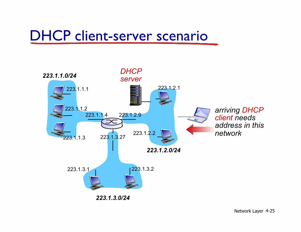
Network Layer 4-25
DHCP client-server scenario
223.1.1.0/24
223.1.2.0/24
223.1.3.0/24
223.1.1.1
223.1.1.3
223.1.1.4 223.1.2.9
223.1.3.2 223.1.3.1
223.1.1.2
223.1.3.27 223.1.2.2
223.1.2.1
DHCP server
arriving DHCP client needs address in this network
Network Layer 4-26
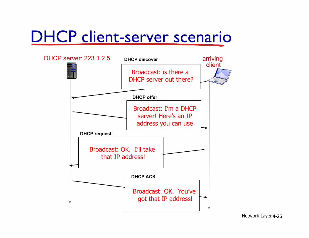
DHCP server: 223.1.2.5 arriving client
DHCP discover
src : 0.0.0.0, 68 dest.: 255.255.255.255,67
yiaddr: 0.0.0.0 transaction ID: 654
DHCP offer src: 223.1.2.5, 67
dest: 255.255.255.255, 68 yiaddrr: 223.1.2.4
transaction ID: 654 lifetime: 3600 secs
DHCP request src: 0.0.0.0, 68
dest:: 255.255.255.255, 67 yiaddrr: 223.1.2.4
transaction ID: 655 lifetime: 3600 secs
DHCP ACK src: 223.1.2.5, 67
dest: 255.255.255.255, 68 yiaddrr: 223.1.2.4
transaction ID: 655 lifetime: 3600 secs
DHCP client-server scenario
Broadcast: is there a DHCP server out there?
Broadcast: I’m a DHCP server! Here’s an IP address you can use
Broadcast: OK. I’ll take that IP address!
Broadcast: OK. You’ve got that IP address!
Network Layer 4-27
DHCP: more than IP addresses
DHCP can return more than just allocated IP address on subnet: § address of first-hop router for client § name and IP address of DNS sever § network mask (indicating network versus host portion
of address)
Network Layer 4-28
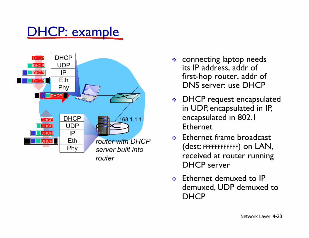
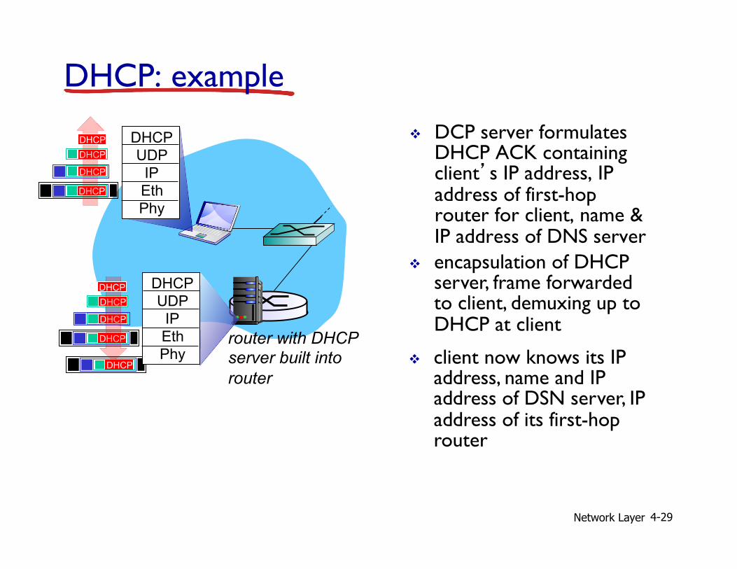
v connecting laptop needs its IP address, addr of first-hop router, addr of DNS server: use DHCP
router with DHCP server built into router
v DHCP request encapsulated in UDP, encapsulated in IP, encapsulated in 802.1 Ethernet
v Ethernet frame broadcast (dest: FFFFFFFFFFFF) on LAN, received at router running DHCP server
v Ethernet demuxed to IP demuxed, UDP demuxed to DHCP
168.1.1.1
DHCP UDP
IP Eth Phy
DHCP
DHCP
DHCP
DHCP
DHCP
DHCP UDP
IP Eth Phy
DHCP
DHCP
DHCP
DHCP DHCP
DHCP: example
Network Layer 4-29
v DCP server formulates DHCP ACK containing client’s IP address, IP address of first-hop router for client, name & IP address of DNS server
v encapsulation of DHCP server, frame forwarded to client, demuxing up to DHCP at client
DHCP: example
router with DHCP server built into router
DHCP
DHCP
DHCP
DHCP
DHCP UDP
IP Eth Phy
DHCP
DHCP UDP
IP Eth Phy
DHCP
DHCP
DHCP
DHCP
v client now knows its IP address, name and IP address of DSN server, IP address of its first-hop router
Network Layer 4-30
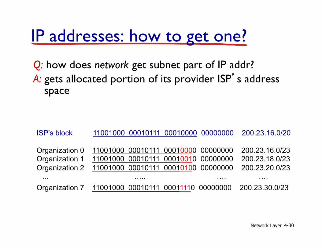
IP addresses: how to get one? Q: how does network get subnet part of IP addr? A: gets allocated portion of its provider ISP’s address
space
ISP's block 11001000 00010111 00010000 00000000 200.23.16.0/20 Organization 0 11001000 00010111 00010000 00000000 200.23.16.0/23 Organization 1 11001000 00010111 00010010 00000000 200.23.18.0/23 Organization 2 11001000 00010111 00010100 00000000 200.23.20.0/23 ... ….. …. …. Organization 7 11001000 00010111 00011110 00000000 200.23.30.0/23
Network Layer 4-31
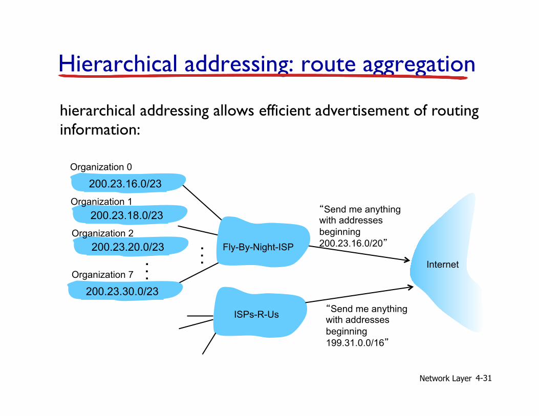
Hierarchical addressing: route aggregation
“Send me anything with addresses beginning 200.23.16.0/20”
200.23.16.0/23
200.23.18.0/23
200.23.30.0/23
Fly-By-Night-ISP
Organization 0
Organization 7 Internet
Organization 1
ISPs-R-Us “Send me anything with addresses beginning 199.31.0.0/16”
200.23.20.0/23 Organization 2
. . .
. . .
hierarchical addressing allows efficient advertisement of routing information:

Network Layer 4-32
ISPs-R-Us has a more specific route to Organization 1
“Send me anything with addresses beginning 200.23.16.0/20”
200.23.16.0/23
200.23.18.0/23
200.23.30.0/23
Fly-By-Night-ISP
Organization 0
Organization 7 Internet
Organization 1
ISPs-R-Us “Send me anything with addresses beginning 199.31.0.0/16 or 200.23.18.0/23”
200.23.20.0/23 Organization 2
. . .
. . .
Hierarchical addressing: more specific routes
Network Layer 4-33
IP addressing: the last word...
Q: how does an ISP get block of addresses? A: ICANN: Internet Corporation for Assigned Names and Numbers http://www.icann.org/
§ allocates addresses § manages DNS § assigns domain names, resolves disputes
Network Layer 4-34
Questions