cs740 - review aditya akella 01/25/08. network communication: lots of functions needed links...
TRANSCRIPT

CS740 - Review
Aditya Akella
01/25/08
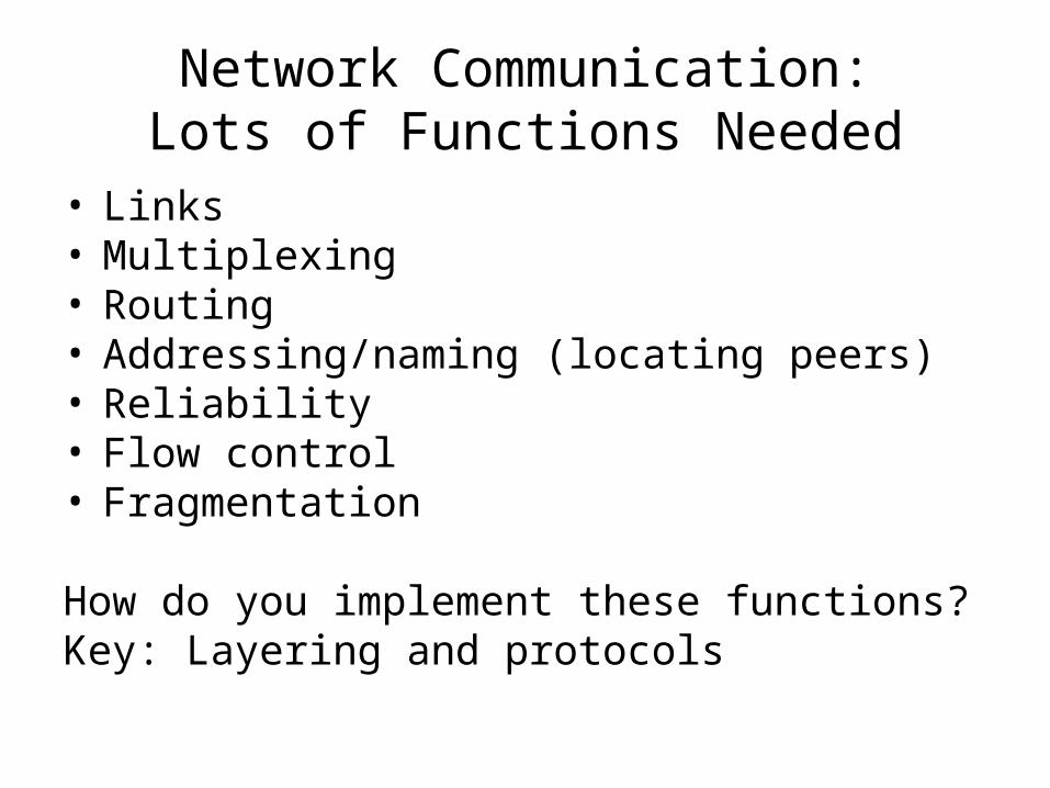
Network Communication:Lots of Functions Needed
• Links• Multiplexing • Routing• Addressing/naming (locating peers)• Reliability• Flow control• Fragmentation
How do you implement these functions?Key: Layering and protocols
What is Layering?• A way to deal with complexity
– Add multiple levels of abstraction– Each level encapsulates some key functionality– And exports an interface to other components– Example?
• Layering: Modular approach to implementing network functionality by introducing abstractions
• Challenge: how to come up with the “right” abstractions?
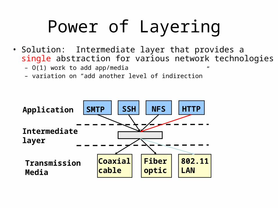
Power of Layering • Solution: Intermediate layer that provides a single
abstraction for various network technologies– O(1) work to add app/media– variation on “add another level of indirection”
SMTP SSH NFS
802.11LAN
Coaxial cable
Fiberoptic
Application
TransmissionMedia
HTTP
Intermediate layer
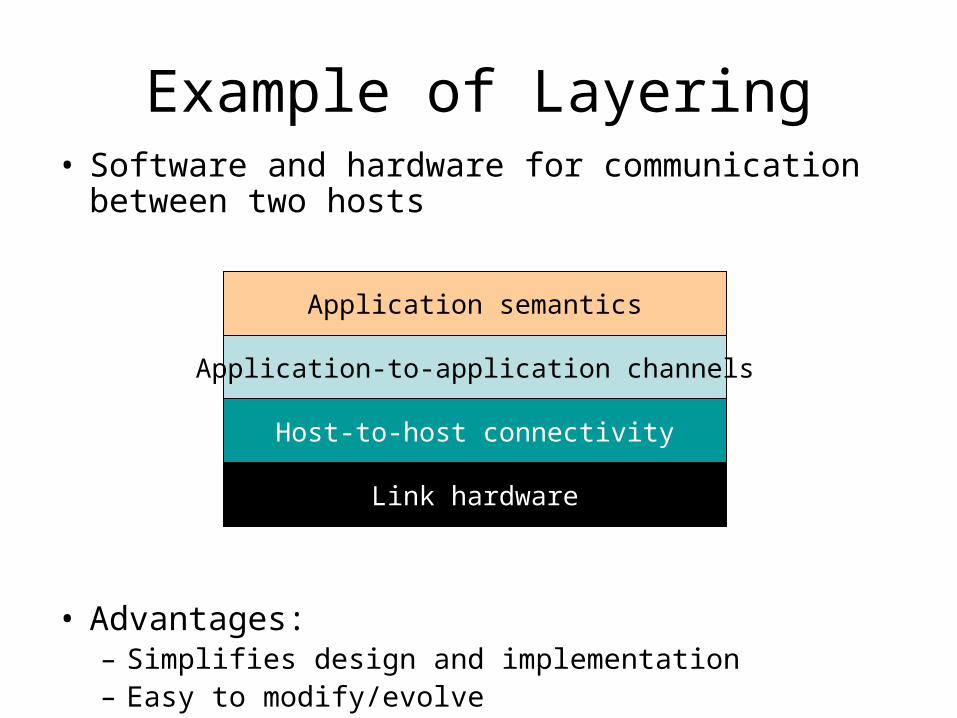
Example of Layering• Software and hardware for communication
between two hosts
• Advantages:– Simplifies design and implementation– Easy to modify/evolve
Link hardware
Host-to-host connectivity
Application-to-application channels
Application semantics
Layering vs Not
• Layer N may duplicate layer N-1 functionality – E.g., error recovery
• Layers may need same info (timestamp, MTU)
• Strict adherence to layering may hurt performance
• Some layers are not always cleanly separated– Inter-layer dependencies in implementations for performance reasons– Many cross-layer assumptions, e.g. buffer management
• Layer interfaces are not really standardized.– It would be hard to mix and match layers from independent
implementations, e.g., windows network apps on unix (w/o compatibility library)
Packet Switching
• Packet-switching: Benefits– Ability to exploit statistical multiplexing– More efficient bandwidth usage
• Packet switching: Concerns – Needs to buffer and deal with congestion:– More complex switches– Harder to provide good network services
(e.g., delay and bandwidth guarantees)
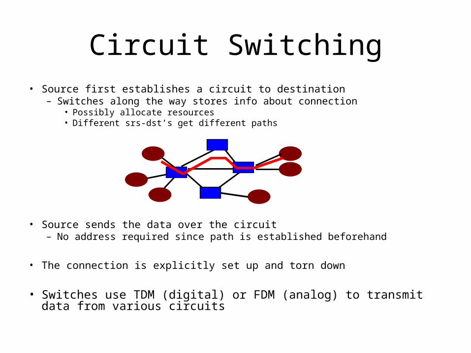
Circuit Switching• Source first establishes a circuit to destination
– Switches along the way stores info about connection• Possibly allocate resources• Different srs-dst’s get different paths
• Source sends the data over the circuit– No address required since path is established beforehand
• The connection is explicitly set up and torn down
• Switches use TDM (digital) or FDM (analog) to transmit data from various circuits
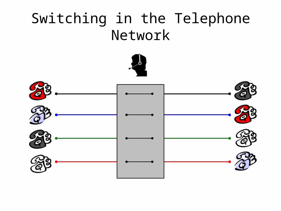
Switching in the Telephone Network
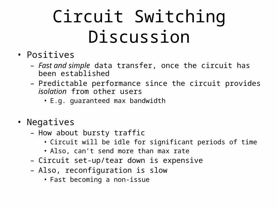
Circuit Switching Discussion
• Positives– Fast and simple data transfer, once the circuit has been
established– Predictable performance since the circuit provides isolation from
other users• E.g. guaranteed max bandwidth
• Negatives– How about bursty traffic
• Circuit will be idle for significant periods of time• Also, can’t send more than max rate
– Circuit set-up/tear down is expensive– Also, reconfiguration is slow
• Fast becoming a non-issue
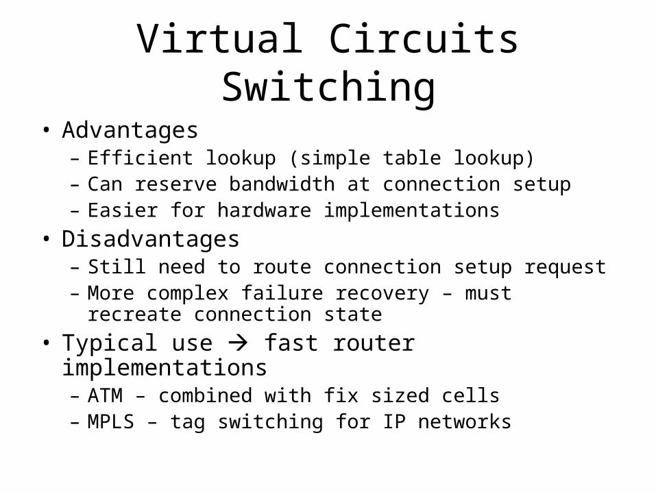
Virtual Circuits Switching
• Advantages– Efficient lookup (simple table lookup)– Can reserve bandwidth at connection setup– Easier for hardware implementations
• Disadvantages– Still need to route connection setup request– More complex failure recovery – must recreate
connection state
• Typical use fast router implementations– ATM – combined with fix sized cells– MPLS – tag switching for IP networks
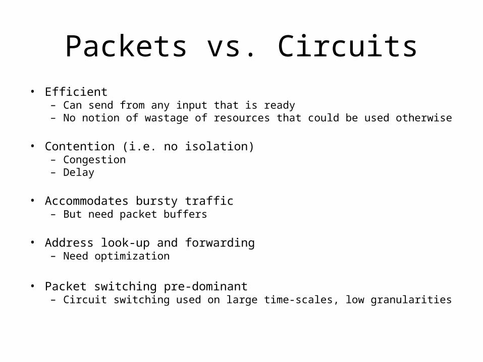
Packets vs. Circuits• Efficient
– Can send from any input that is ready– No notion of wastage of resources that could be used otherwise
• Contention (i.e. no isolation)– Congestion– Delay
• Accommodates bursty traffic– But need packet buffers
• Address look-up and forwarding– Need optimization
• Packet switching pre-dominant– Circuit switching used on large time-scales, low granularities

Outline
• Switching and Multiplexing
• Link-Layer– Ethernet and CSMA/CD– Bridges/Switches
• Routing-Layer
• Physical-Layer
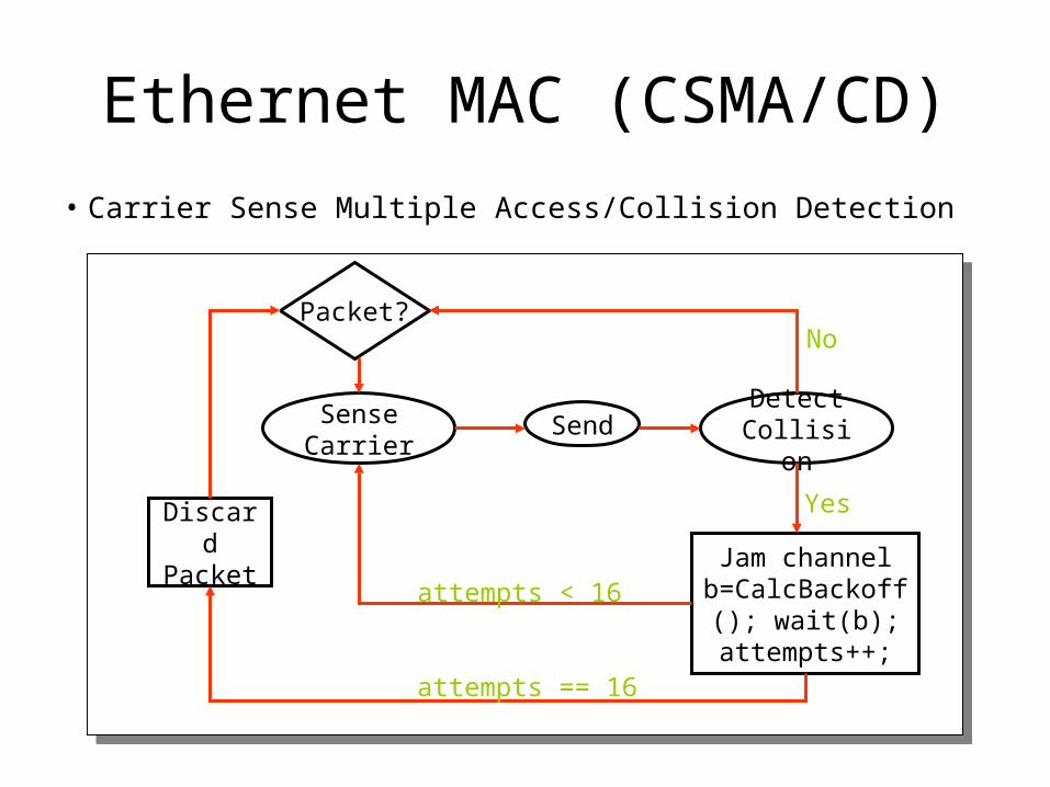
Ethernet MAC (CSMA/CD)
Packet?
Sense Carrier
Discard Packet
Send Detect Collision
Jam channel b=CalcBackoff();
wait(b);attempts++;
No
Yes
attempts < 16
attempts == 16
• Carrier Sense Multiple Access/Collision Detection
15
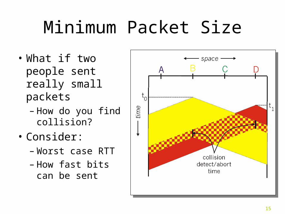
Minimum Packet Size
• What if two people sent really small packets– How do you find
collision?
• Consider:– Worst case RTT– How fast bits can
be sent
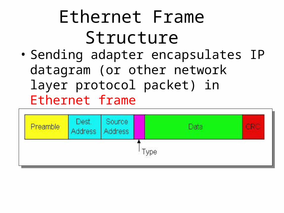
Ethernet Frame Structure
• Sending adapter encapsulates IP datagram (or other network layer protocol packet) in Ethernet frame
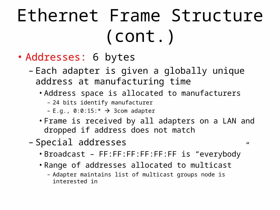
Ethernet Frame Structure (cont.)
• Addresses: 6 bytes– Each adapter is given a globally unique address at
manufacturing time• Address space is allocated to manufacturers
– 24 bits identify manufacturer– E.g., 0:0:15:* 3com adapter
• Frame is received by all adapters on a LAN and dropped if address does not match
– Special addresses• Broadcast – FF:FF:FF:FF:FF:FF is “everybody”• Range of addresses allocated to multicast
– Adapter maintains list of multicast groups node is interested in
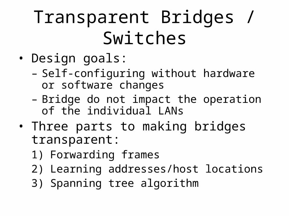
Transparent Bridges / Switches
• Design goals:– Self-configuring without hardware or software
changes– Bridge do not impact the operation of the
individual LANs
• Three parts to making bridges transparent:1) Forwarding frames2) Learning addresses/host locations3) Spanning tree algorithm
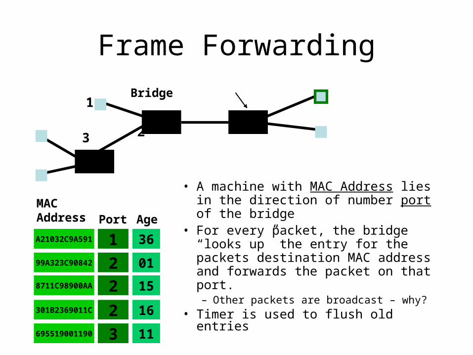
Frame Forwarding
• A machine with MAC Address lies in the direction of number port of the bridge
• For every packet, the bridge “looks up” the entry for the packets destination MAC address and forwards the packet on that port.– Other packets are broadcast – why?
• Timer is used to flush old entries
8711C98900AA 2
MAC Address Port
A21032C9A591 199A323C90842 2
301B2369011C 2695519001190 3
15
Age
36
01
16
11
Bridge1
3 2
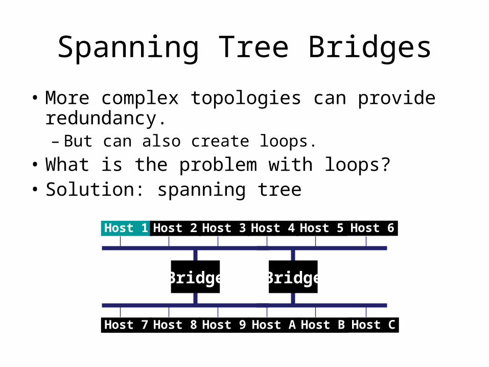
Spanning Tree Bridges
• More complex topologies can provide redundancy.– But can also create loops.
• What is the problem with loops?• Solution: spanning tree
Host 1 Host 2 Host 3 Host 4 Host 5
Host 7 Host 8 Host 9 Host A Host B
Host 6
Host C
Bridge Bridge

Outline
• Switching and Multiplexing
• Link-Layer
• Routing-Layer– IP– IP Routing– MPLS
• Physical-Layer
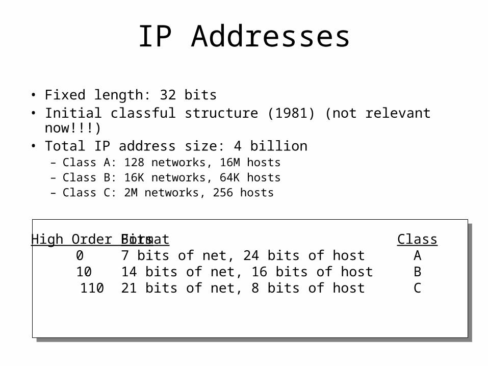
IP Addresses
• Fixed length: 32 bits• Initial classful structure (1981) (not relevant now!!!)• Total IP address size: 4 billion
– Class A: 128 networks, 16M hosts– Class B: 16K networks, 64K hosts– Class C: 2M networks, 256 hosts
High Order Bits0 10 110
Format7 bits of net, 24 bits of host14 bits of net, 16 bits of host21 bits of net, 8 bits of host
ClassABC
Subnet AddressingRFC917 (1984)
• Class A & B networks too big– Very few LANs have close to 64K hosts– For electrical/LAN limitations, performance or
administrative reasons
• Need simple way to get multiple “networks”– Use bridging, multiple IP networks or split up single
network address ranges (subnet)
• CMU case study in RFC– Chose not to adopt – concern that it would not be
widely supported
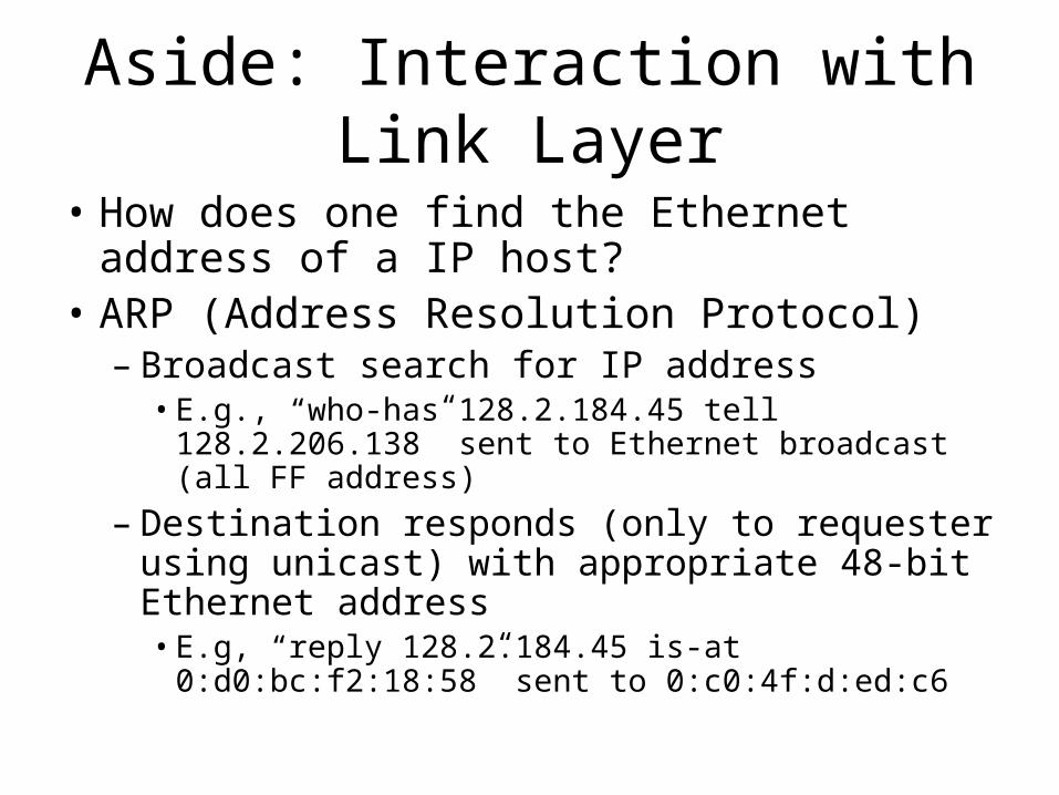
Aside: Interaction with Link Layer
• How does one find the Ethernet address of a IP host?
• ARP (Address Resolution Protocol)– Broadcast search for IP address
• E.g., “who-has 128.2.184.45 tell 128.2.206.138” sent to Ethernet broadcast (all FF address)
– Destination responds (only to requester using unicast) with appropriate 48-bit Ethernet address• E.g, “reply 128.2.184.45 is-at 0:d0:bc:f2:18:58” sent
to 0:c0:4f:d:ed:c6
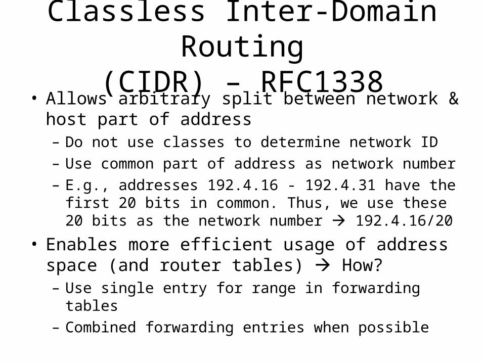
Classless Inter-Domain Routing(CIDR) – RFC1338
• Allows arbitrary split between network & host part of address – Do not use classes to determine network ID– Use common part of address as network number– E.g., addresses 192.4.16 - 192.4.31 have the first 20
bits in common. Thus, we use these 20 bits as the network number 192.4.16/20
• Enables more efficient usage of address space (and router tables) How?– Use single entry for range in forwarding tables– Combined forwarding entries when possible
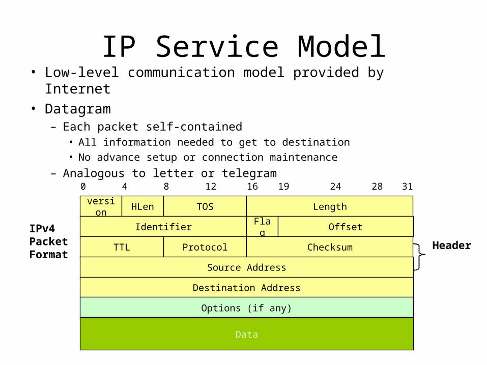
IP Service Model• Low-level communication model provided by Internet• Datagram
– Each packet self-contained• All information needed to get to destination
• No advance setup or connection maintenance
– Analogous to letter or telegram0 4 8 12 16 19 24 28 31
version HLen TOS Length
Identifier Flag Offset
TTL Protocol Checksum
Source Address
Destination Address
Options (if any)
Data
Header
IPv4 PacketFormat
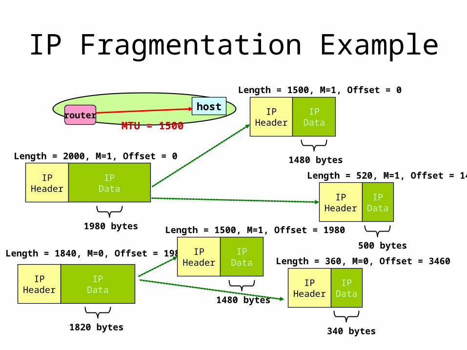
IP Fragmentation Example
IPHeader
IPData
Length = 2000, M=1, Offset = 0
1980 bytes
IPData
IPHeader
Length = 1840, M=0, Offset = 1980
1820 bytes
hostrouter
MTU = 1500
IPHeader
IPData
Length = 1500, M=1, Offset = 0
1480 bytes
IPHeader
IPData
Length = 520, M=1, Offset = 1480
500 bytesIP
HeaderIP
Data
Length = 1500, M=1, Offset = 1980
1480 bytes
IPHeader
IPData
Length = 360, M=0, Offset = 3460
340 bytes
Important Concepts
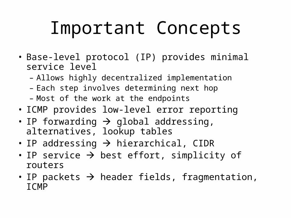
• Base-level protocol (IP) provides minimal service level– Allows highly decentralized implementation– Each step involves determining next hop– Most of the work at the endpoints
• ICMP provides low-level error reporting• IP forwarding global addressing, alternatives,
lookup tables• IP addressing hierarchical, CIDR• IP service best effort, simplicity of routers• IP packets header fields, fragmentation, ICMP
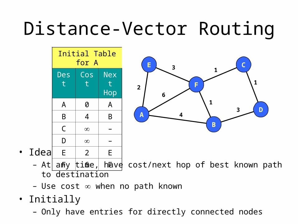
Distance-Vector Routing
• Idea– At any time, have cost/next hop of best known path to destination– Use cost when no path known
• Initially– Only have entries for directly connected nodes
A
E
F
C
D
B
2
3
6
4
1
1
1
3
Initial Table for A
Dest Cost Next Hop
A 0 A
B 4 B
C –
D –
E 2 E
F 6 F
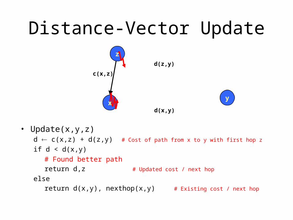
Distance-Vector Update
• Update(x,y,z)d c(x,z) + d(z,y) # Cost of path from x to y with first hop z
if d < d(x,y)
# Found better path
return d,z # Updated cost / next hop
else
return d(x,y), nexthop(x,y) # Existing cost / next hop
x
z
y
c(x,z)
d(z,y)
d(x,y)
Link State Protocol Concept
• Every node gets complete copy of graph– Every node “floods” network with data about
its outgoing links
• Every node computes routes to every other node– Using single-source, shortest-path algorithm
• Process performed whenever needed– When connections die / reappear

Sending Link States by Flooding
• X Wants to Send Information– Sends on all outgoing
links
• When Node B Receives Information from A– Send on all links other
than A
X A
C B D
(a)
X A
C B D
(b)
X A
C B D
(c)
X A
C B D
(d)
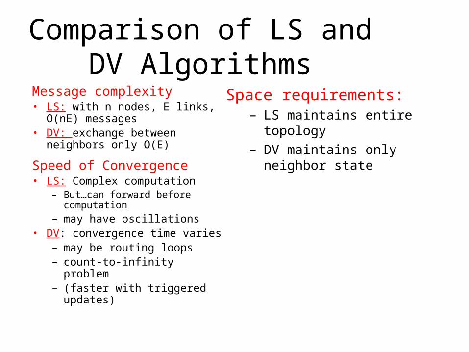
Comparison of LS and DV Algorithms
Message complexity• LS: with n nodes, E links, O(nE)
messages• DV: exchange between
neighbors only O(E)
Speed of Convergence• LS: Complex computation
– But…can forward before computation
– may have oscillations• DV: convergence time varies
– may be routing loops– count-to-infinity problem– (faster with triggered
updates)
Space requirements:– LS maintains entire
topology– DV maintains only neighbor
state

Inter-domain Routing: Hierarchy
• “Flat” routing not suited for the Internet– Doesn’t scale with network size
• Storage Each node cannot be expected to store routes to every destination (or destination network)
• Convergence times increase• Communication Total message count increases
– Administrative autonomy• Each internetwork may want to run its network independently
– E.g hide topology information from competitors
• Solution: Hierarchy via autonomous systems
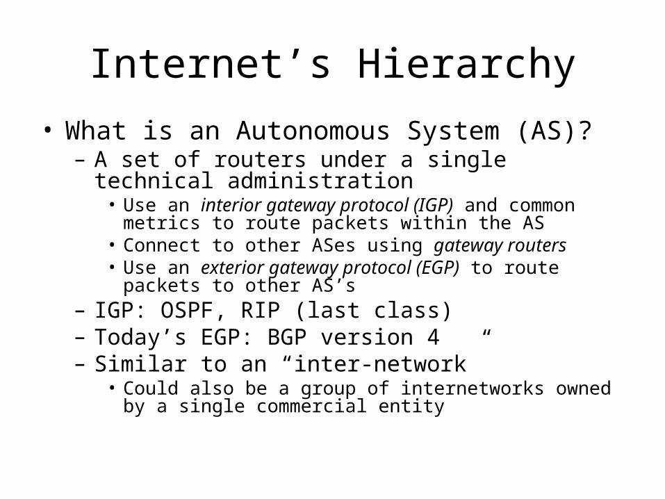
Internet’s Hierarchy
• What is an Autonomous System (AS)?– A set of routers under a single technical
administration• Use an interior gateway protocol (IGP) and common metrics
to route packets within the AS• Connect to other ASes using gateway routers• Use an exterior gateway protocol (EGP) to route packets to
other AS’s– IGP: OSPF, RIP (last class)– Today’s EGP: BGP version 4– Similar to an “inter-network”
• Could also be a group of internetworks owned by a single commercial entity
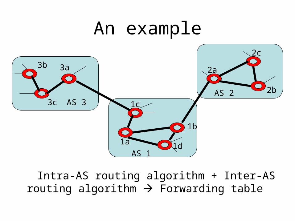
An example
Intra-AS routing algorithm + Inter-AS routing algorithm Forwarding table
3b 3a
3c 1c
1a
1b
1d
2a
2c
2bAS 2AS 3
AS 1
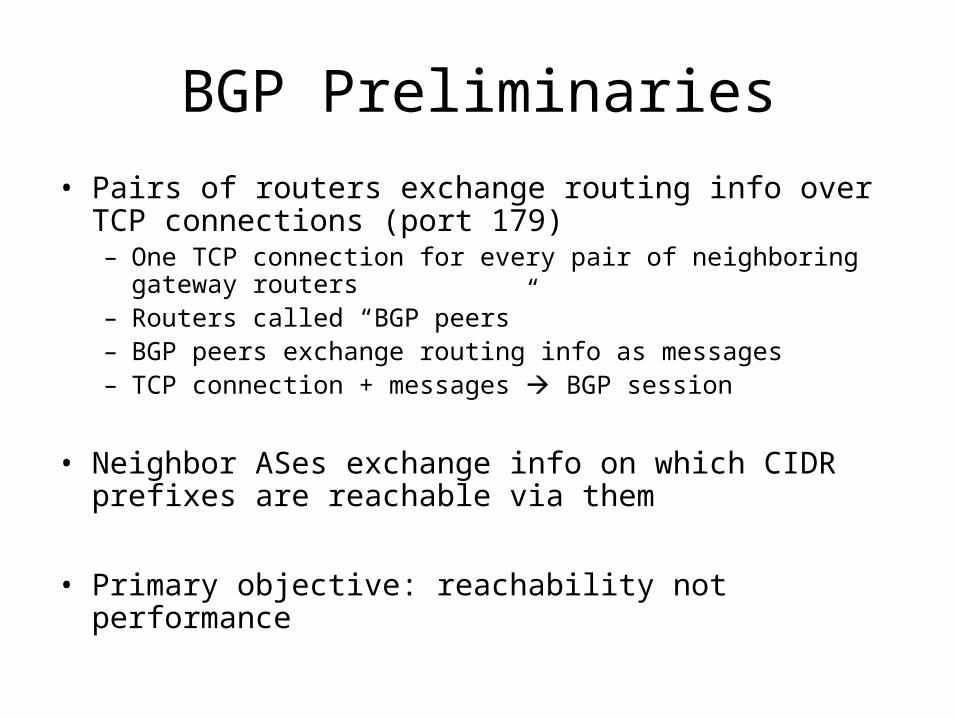
BGP Preliminaries
• Pairs of routers exchange routing info over TCP connections (port 179)– One TCP connection for every pair of neighboring gateway
routers– Routers called “BGP peers”– BGP peers exchange routing info as messages– TCP connection + messages BGP session
• Neighbor ASes exchange info on which CIDR prefixes are reachable via them
• Primary objective: reachability not performance
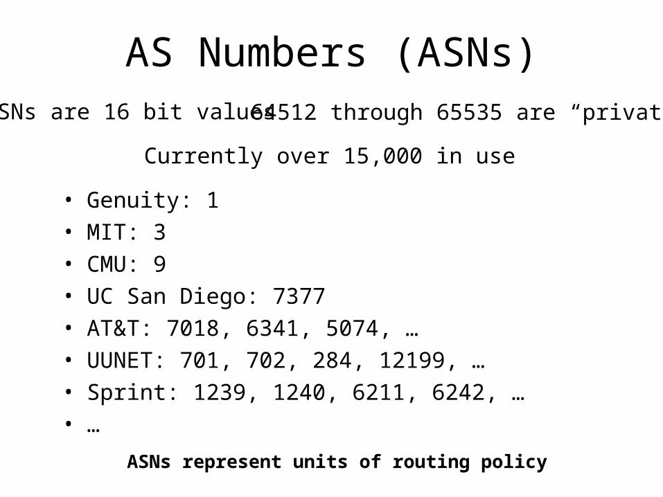
AS Numbers (ASNs)ASNs are 16 bit values 64512 through 65535 are “private”
ASNs represent units of routing policy
Currently over 15,000 in use
• Genuity: 1 • MIT: 3• CMU: 9• UC San Diego: 7377• AT&T: 7018, 6341, 5074, … • UUNET: 701, 702, 284, 12199, …• Sprint: 1239, 1240, 6211, 6242, …• …
Distance Vector with Path
• Each routing update carries the entire AS-level path so far– “AS_Path attribute”
• Loops are detected as follows:– When AS gets route, check if AS already in path
• If yes, reject route• If no, add self and (possibly) advertise route further
– Advertisement depends on metrics/cost/preference etc.
• Advantage:– Metrics are local - AS chooses path, protocol ensures
no loops
Hop-by-hop Model
• BGP advertises to neighbors only those routes that it uses– Consistent with the hop-by-hop Internet
paradigm– Consequence: hear only one route from
neighbor • (although neighbor may have chosen this from a
large set of choices)• Could impact view into availability of paths
Policy with BGP
• BGP provides capability for enforcing various policies
• Policies are not part of BGP: they are provided to BGP as configuration information
• Enforces policies by – Choosing appropriate paths from multiple alternatives– Controlling advertisement to other AS’s
Examples of BGP Policies
• A multi-homed AS refuses to act as transit– Limit path advertisement
• A multi-homed AS can become transit for some AS’s– Only advertise paths to some AS’s
• An AS can favor or disfavor certain AS’s for traffic transit from itself
BGP Messages
• Open– Announces AS ID– Determines hold timer – interval between keep_alive or update
messages, zero interval implies no keep_alive
• Keep_alive• Sent periodically (but before hold timer expires) to peers to
ensure connectivity.• Sent in place of an UPDATE message
• Notification• Used for error notification• TCP connection is closed immediately after notification
BGP UPDATE Message
• List of withdrawn routes
• Network layer reachability information– List of reachable prefixes
• Path attributes– Origin– Path– Local_pref this is set locally– MED this is set externally– Metrics
• All prefixes advertised in message have same path attributes
Path Selection Criteria
• Attributes + external (policy) information
• Examples:– Policy considerations
• Preference for AS• Presence or absence of certain AS
– Hop count– Path origin
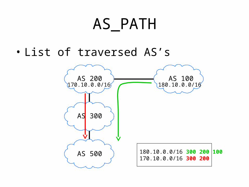
AS_PATH
• List of traversed AS’s
AS 500
AS 300
AS 200 AS 100
180.10.0.0/16 300 200 100170.10.0.0/16 300 200
170.10.0.0/16 180.10.0.0/16
Decision Process (First cut)
• Rough processing order of attributes:– Select route with highest LOCAL-PREF– Select route with shortest AS-PATH
• How to set the attributes?– Especially local_pref?– Policies in action

A Logical View of the Internet
Tier 1 Tier 1
Tier 2
Tier 2
Tier 2
Tier 3
• Tier 1 ISP– “Default-free” with global
reachability info
• Tier 2 ISP– Regional or country-wide
– Typically route through tier-1• Customer
• Tier 3/4 ISPs– Local
– Route through higher tiers
• Stub AS– End network such as IBM or
UW-Madison
Stub
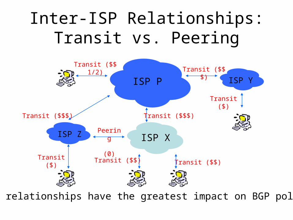
Inter-ISP Relationships:Transit vs. Peering
ISP X
ISP Y
ISP Z
ISP P
Transit ($)
Transit ($$$)
Transit ($$ 1/2)
Transit ($$)
Peering
(0)
Transit ($$$)
Transit ($)
Transit ($$)
Transit ($$$)
These relationships have the greatest impact on BGP policies

50
Which route shouldFrank pick to 13.13.0.0./16?
AS 1
AS 2
AS 4
AS 3
13.13.0.0/16
Frank’s Internet Barn
peer peer
customerprovider
Illustrating BGP Policies
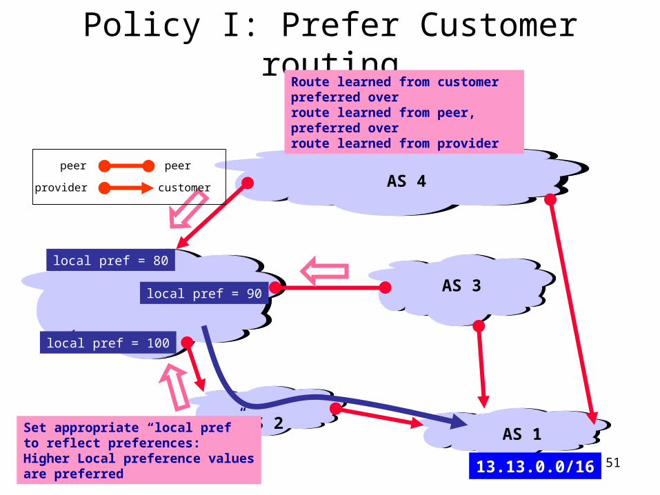
51
AS 1AS 2
AS 4
AS 3
13.13.0.0/16
local pref = 80
local pref = 100
local pref = 90
Set appropriate “local pref”to reflect preferences:Higher Local preference valuesare preferred
Policy I: Prefer Customer routing
peer peer
customerprovider
Route learned from customer preferred over route learned from peer, preferred over route learned from provider
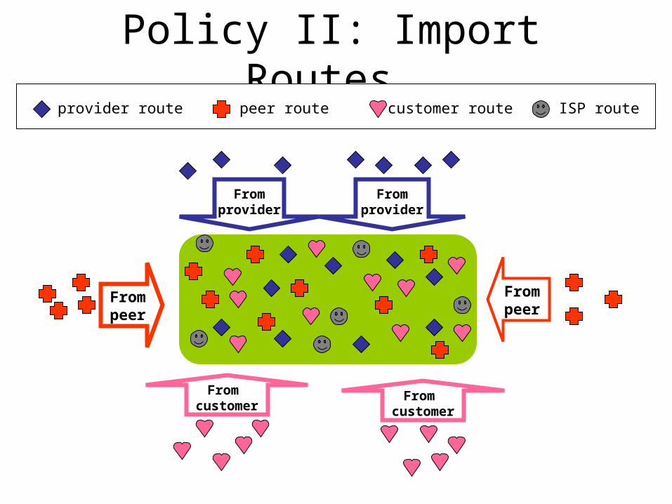
Policy II: Import Routes
Frompeer
Frompeer
Fromprovider
Fromprovider
From customer
From customer
provider route customer routepeer route ISP route
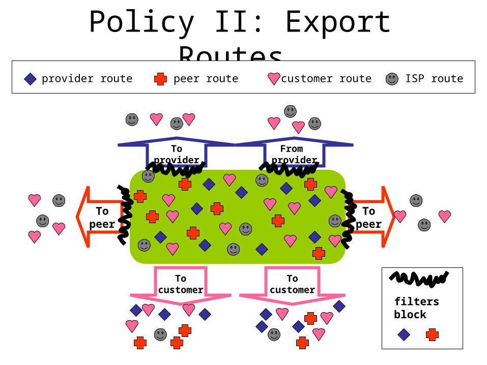
Policy II: Export Routes
Topeer
Topeer
Tocustomer
Tocustomer
Toprovider
From provider
provider route customer routepeer route ISP route
filtersblock
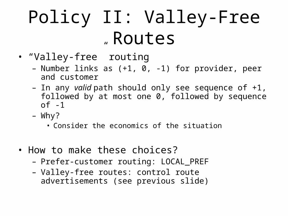
Policy II: Valley-Free Routes
• “Valley-free” routing– Number links as (+1, 0, -1) for provider, peer and customer– In any valid path should only see sequence of +1, followed by at
most one 0, followed by sequence of -1– Why?
• Consider the economics of the situation
• How to make these choices?– Prefer-customer routing: LOCAL_PREF– Valley-free routes: control route advertisements (see previous
slide)
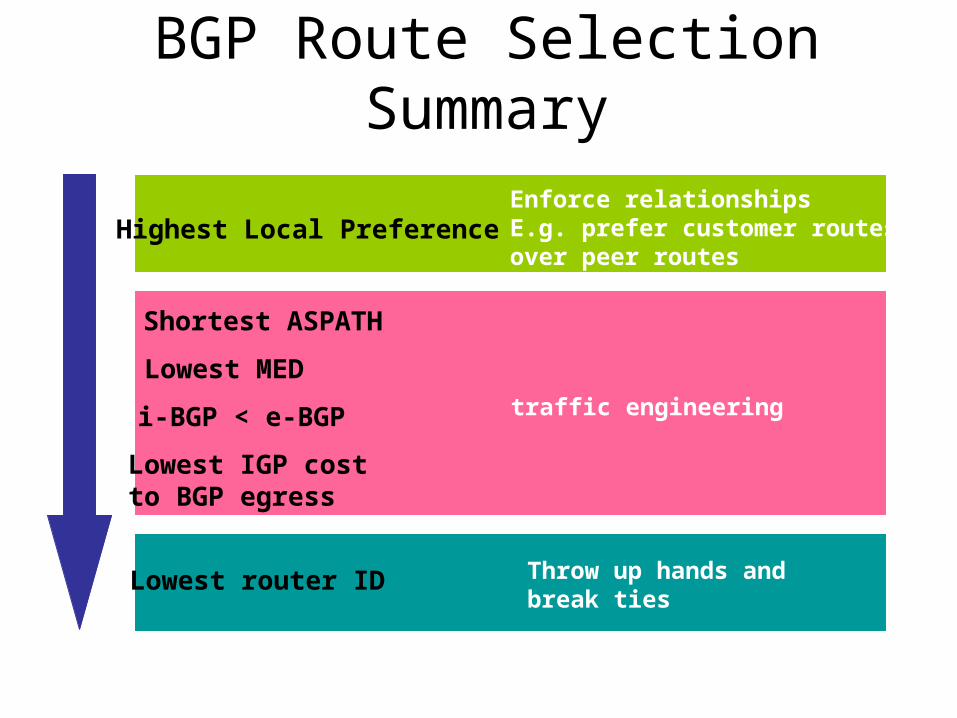
BGP Route Selection Summary
Highest Local Preference
Shortest ASPATH
Lowest MED
i-BGP < e-BGP
Lowest IGP cost to BGP egress
Lowest router ID
traffic engineering
Enforce relationshipsE.g. prefer customer routes over peer routes
Throw up hands andbreak ties