cse 461: bits and bandwidth jeremy elson ([email protected])[email protected] microsoft research ben...
TRANSCRIPT
CSE 461: Bits and Bandwidth
Jeremy Elson ([email protected])Microsoft Research
Ben Greenstein ([email protected])Intel Research
October 1, 2008

Homework
68131617192332
Chapter 1, written problems
Due 11:59pm next Wednesday, October 8Submit by mailing it to the TA -- Alper

Next Topic
Focus: How do we send a message across a wire?
The physical / link layers:1. Different kinds of media2. Encoding bits, messages3. Model of a link
Physical
Data Link
Network
Transport
Session
Presentation
Application

Our Challenge Today: Transmit Bits
Transmit some bits from A to B How quickly can we transmit them? How far can we transmit them? How are these two questions related?
Thought Experiment:
Why can’t you speak quickly someplace where there is a lot of echo – like in a sauna?
Why is it easier to understand someone speaking in your ear quietly than someone speaking from a few feet away – even with equal perceived volume?

A Very Simple Digital Network
We agree that once per second, you should look at the bulb.If it flashes, I sent a 1. If it doesn’t, I sent a 0.
How quickly can we transmit bits? What happens when we transmit too quickly?
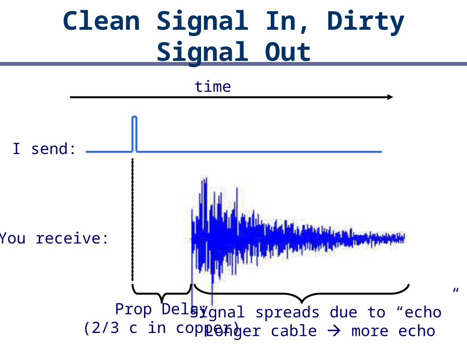
Clean Signal In, Dirty Signal Out
time
I send:
You receive:
Prop Delay(2/3 c in copper)
Signal spreads due to “echo”Longer cable more echo

Slow bits vs. Fast bits
Send too fast, the bits are not detectable
Slow down, or make
the cable shorter!
0
0 0 01
1 1
11
????????????????????????

Problem 2: Noise
What happens when a magnetic field comes near a loop of copper
wire?

Noise from the Environment
0
0 01
1 1
11
Despite a burst of noise,the bit is still under the “0” detection threshold.
1!!This bit wasn’t so lucky.
Bits transmitted faster are closer to the detection threshold,
and are therefore more susceptible to noise.
Signal to Noise Ratio is strongly related to channel capacity (Shannon)

Twisted Pair
Why does it work?Why should the twists be spaced closely together?
“Cat 5”: Category 5, relates to required impedance, prop
delay, twist density, etc
“UTP”: Unshielded Twisted Pair

Early types of Ethernet tried to reduce noise purely
through shielding
Shielded twisted pair exists;Sometimes used in hostile
buildings (e.g., factory)
“Solid” vs “Stranded” cable:Conductors are made of a
single, thick strand of copper (inflexible, but low
dispersion) or a copper braid (more flexible, but higher
dispersion)
Ethernet has1 RX pair, 1 TX pair,2 unused pairs

Fiber Optic Cable
Long, thin, pure strand of glass light propagated with total internal reflection enormous bandwidth available (terabits)
Light source(LED, laser)
Light detector(photodiode)
Light source(LED, laser)
Light detector(photodiode)
Multi-Mode
Single-Mode
Which is better?

Summary: media
Copper Wire +Cheap, +Easy to handle, +Mech. Robust, –Noisy Coaxial cable, e.g, thin-net, 10 100Mbps, 200m –Bus Twisted pair, e.g., CAT5 UTP, 10 100Mbps, 100m
+Star Fiber
+Noise-immune, +Low-dispersion, –Expensive, –Difficult, –Fragile Multi-mode, 100Mbps, 2km Single mode, 100 10 Gbps, 60km Single mode with amplifiers & other fanciness 1000km
Wireless Infra-red, e.g., IRDA, ~1Mbps RF, e.g., 802.11 wireless LANs, Bluetooth (2.4GHz) Microwave, satellite, cell phones, …
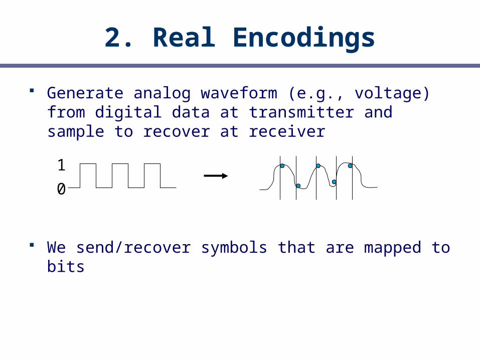
2. Real Encodings
Generate analog waveform (e.g., voltage) from digital data at transmitter and sample to recover at receiver
We send/recover symbols that are mapped to bits
0
1

NRZ
Simplest encoding, NRZ (Non-return to zero) Use high/low voltages, e.g., high = 1, low = 0
Bits
NRZ
0 0 1 0 1 1 1 1 0 1 0 0 0 0 1 0

Clock Recovery
How do we distinguish consecutive 0s or 1s? Easy, right?
If sender and receiver have exact clocks no problem But in practice they drift slowly
Possible solutions: Get really good clocks super expensive (mini-atomic clocks?) Send clock signal (“synchronous”) huge overhead, expensive Keep messages short lots of overhead Embed clock signal in data signal other codes: DING DING
DING!
0 0 1 0 1 1 0 1 0 0 1
1 0 0 0 0 0 0…? Now what, punk?

NRZI
NRZI (NRZ Inverted): “stay at same voltage” means “0” “voltage change” means “1”
Bits
NRZ
0 0 1 0 1 1 1 1 0 1 0 0 0 0 1 0
NRZI
Now a long sequence of 1s works really well.
You didn’t really need zeroes, did you?

Manchester CodingBits
NRZ
Manchester
0 0 1 0 1 1 1 1 0 1 0 0 0 0 1 0
NRZI
Clock
Make transition in the middle of every bit period Low-to-high is 0; high-to-low is 1 Signal rate is twice the bit rate
Advantage: self-clocking Disadvantage: 50% efficiency
(not actuallytransmitted)

4B/5B Codes
We want self-clocking transitions and efficiency … Solution: map data bits (which may lack transitions)
into code bits (which are guaranteed to have them)
4B/5B code: 0000 11110, 0001 01001, … 1111 11101 Never more than three consecutive 0s back-to-
back 80% efficiency
Many more complex codes are available; some use multiple voltage levels How does a 3-voltage system interact with noise
and speed?
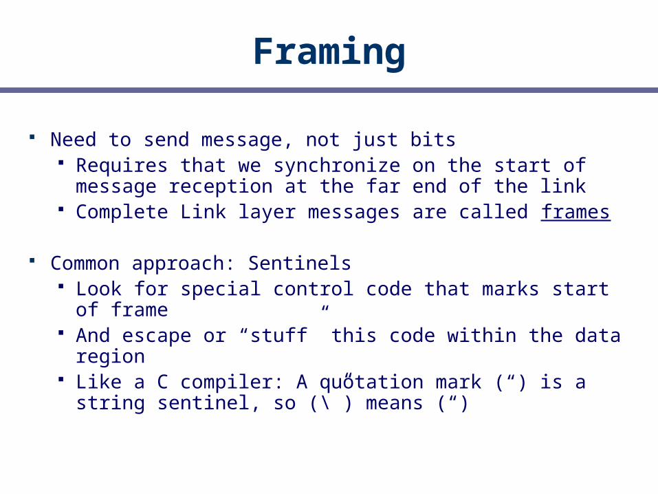
Framing
Need to send message, not just bits Requires that we synchronize on the start of
message reception at the far end of the link Complete Link layer messages are called frames
Common approach: Sentinels Look for special control code that marks start of
frame And escape or “stuff” this code within the data region Like a C compiler: A quotation mark (“) is a string
sentinel, so (\”) means (“)

4. Model of a Link
Abstract model is typically all we will need
Other parameters that are important: The kind and frequency of errors Whether the media is broadcast or not
MessageM bits
Rate R Mbps
Delay D seconds

Message Latency
How long does it take to send a message?
Two terms: Propagation delay = distance / speed of signal in
media• How quickly a message travels over the wire• 2/3c for copper wire
Transmission delay = message (bits) / rate (bps)• How quickly you can inject the message onto the wire
Propagation delay tells you when the FIRST bit arrives,Transmission delay tells you when the LAST bit arrives.
Later we will see queuing delay …
Delay D, Rate R
Message M

Relationships
Latency = Propagation + Transmit + Queue Propagation Delay = Distance/PropagationSpeed Transmit Time = MessageSize/Bandwidth

One-way Latency
Dialup with a modem: D = 10ms, R = 56Kbps, M = 1024 bytes Latency = 10ms + (1024 x 8)/(56 x 1024) sec
= 153ms!Cross-country with T3 (45Mbps) line:
D = 50ms, R = 45Mbps, M = 1024 bytes Latency = 50ms + (1024 x 8) / (45 x
1024*1024) sec = 50ms!
Either a slow link or long wire makes for large latency

Latency and RTT
Latency is typically the one way delay over a link Arrival Time - Departure Time
The round trip time (RTT) is twice the one way delay Measure of how long to signal and get a response
+ RTT
DepartureTime
Arrival Time

Throughput
Measure of system’s ability to “pump out” data NOT the same as bandwidth
Throughput = Transfer Size / Transfer Time E.g., “I transferred 1000 bytes in 1 second on a
100Mb/s link”• BW?• Throughput?
Transfer Time = SUM OF Time to get started shipping the bits Time to ship the bits Time to get a response if necessary

Messages OccupySpace On the Wire
Consider a 1b/s network.
Suppose latency is 16 seconds. How many bits can the network “store” This is the BANDWIDTH-DELAY product Measure of “data in flight.” 1b/s * 16s = 16b
Tells us how much data can be sent before a receiver sees any of it. Twice B.D. tells us how much data we could send before
hearing back from the receiver something related to the first bit sent.
What are the implications of high B.D.?

101100…11…0010101010101010101
A More Realistic Example
BD = 50ms * 45Mbps = 2.25 * 10^6 = 280KB
We’ll see why this is important when we learn about TCP

Key Concepts
Transmitting bits is a complex interplay between speed, noise, error rate, media, coding, and other factors Those details are studied in more detail in EE classes
– they start here and go down, we start here and go up. There are many modulations (not just on/off) and encodings (not just 4b5, Manchester).
We typically model links in terms of bandwidth, delay, and error rate, from which we can calculate message latency
Most of the remainder of the class assumes a link underneath that transmits bits, without us needing to know physical, electrical, or coding details