csm 2014 vapor intrusion mitigation for complex buildings - revised kl - pdf
TRANSCRIPT

2014 – Contaminated Site Management (CSM-2014) Sustainable Remediation & Management of Soil, Sediment and Water
2014 – Contaminated Site Management (CSM-2014) Sustainable Remediation & Management of Soil, Sediment and Water
INNOVATIVE VAPOR INTRUSION
MITIGATION DESIGN FOR COMPLEX
BUILDING FOUNDATIONS
2014 – Contaminated Site Management (CSM-2014) Sustainable Remediation & Management of Soil, Sediment and Water
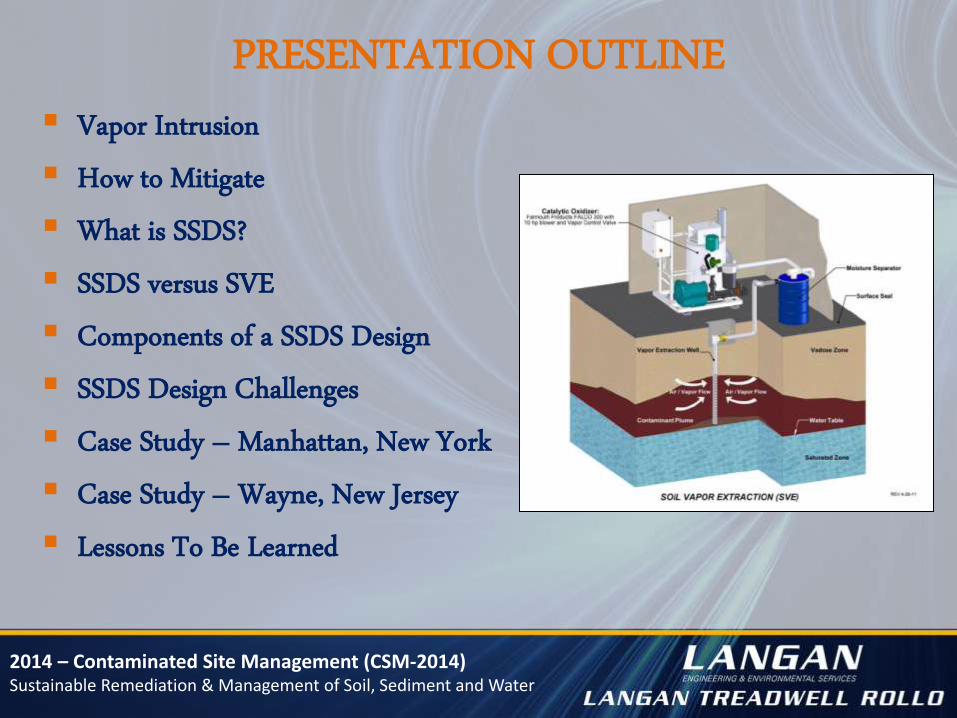
PRESENTATION OUTLINE
Vapor Intrusion
How to Mitigate
What is SSDS?
SSDS versus SVE
Components of a SSDS Design
SSDS Design Challenges
Case Study – Manhattan, New York
Case Study – Wayne, New Jersey
Lessons To Be Learned

2014 – Contaminated Site Management (CSM-2014) Sustainable Remediation & Management of Soil, Sediment and Water
VAPOR INTRUSION Migration of volatile chemicals from contaminated groundwater or
soil into buildings above
Indoor Air Quality
Chronic and acute health/safety hazards

2014 – Contaminated Site Management (CSM-2014) Sustainable Remediation & Management of Soil, Sediment and Water
HOW TO MITIGATE
Passive Venting Systems
Impermeable Membrane Liners
Sub-Slab Depressurization Systems
HVAC/Ventilation System Modifications
http://www.nj.gov/dep/srp/guidance/vaporintrusion/subsurface.htm

2014 – Contaminated Site Management (CSM-2014) Sustainable Remediation & Management of Soil, Sediment and Water
WHAT IS A SSDS?
Active venting system consisting of:
Fan/Blower
Well Network
Vacuum/Air Flow Rate Instrumentation
Control Panel
Telemetry System
Emission Controls

2014 – Contaminated Site Management (CSM-2014) Sustainable Remediation & Management of Soil, Sediment and Water
SSDS VERSUS SVE
Differences: Purpose
MITIGATION versus REMEDIATION
Capture versus Extraction
Similarities: Principals
Active Pneumatic Systems
Dependent on intrinsic permeability

2014 – Contaminated Site Management (CSM-2014) Sustainable Remediation & Management of Soil, Sediment and Water
Mitigation vs. Remediation
Depressurization System SVE System
Objective:
Create a differential pressure barrier between
subsurface and buildings
Design Basis:
Vacuum Gradient = 0.004 – 0.025 IWC
Objective:
Remove contaminants from the vadose zone
Design Basis:
Pore Volume (PV) Exchanges
Sands = 500 PV/year
Silts = 1,500 PV/year
Silty Clays/Clays = 2,500 PV/year
2014 – Contaminated Site Management (CSM-2014) Sustainable Remediation & Management of Soil, Sediment and Water
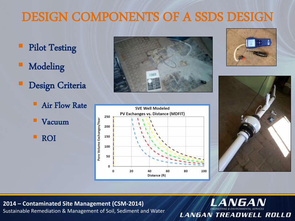
DESIGN COMPONENTS OF A SSDS DESIGN
Pilot Testing
Modeling
Design Criteria
Air Flow Rate
Vacuum
ROI

2014 – Contaminated Site Management (CSM-2014) Sustainable Remediation & Management of Soil, Sediment and Water
SSDS DESIGN CHALLENGES
Equipment Limitations
Vacuum Limitations:
• Industrial fan: 3 to 4 IWC
• Compact radial blower: 10 to 14 IWC
• Regenerative blower: 90 IWC (6.5” Hg)
• PDB: 220 IWC (16” Hg)
• LRP: 350 IWC (28” Hg)
Site Challenges
Slab-on-grade
Low permeability sub-slab material
Shallow water table
Subsurface heterogeneity
Below-grade structures
Non-confining leaky surface layer
Space limitations
Varying partial pressures/Henry’s Law constants
of complex soil gas mixtures

2014 – Contaminated Site Management (CSM-2014) Sustainable Remediation & Management of Soil, Sediment and Water
CASE STUDY – MANHATTAN, NEW YORK

2014 – Contaminated Site Management (CSM-2014) Sustainable Remediation & Management of Soil, Sediment and Water
SITE BACKGROUND
Operated until June 2013 as an active dry cleaning facility
Residential dwellings located on floors two through five.
Indoor air assessment - PCE and TCE in exceedance of NYSDOH
Vapor Intrusion Guidance Matrix.

2014 – Contaminated Site Management (CSM-2014) Sustainable Remediation & Management of Soil, Sediment and Water
SITE CONSTRAINTS
2 - 6 inch thick concrete slab with granite bedrock beneath
Limited space for implementation/Manual drilling required
Possible demolition of building during application period

2014 – Contaminated Site Management (CSM-2014) Sustainable Remediation & Management of Soil, Sediment and Water
PILOT TESTING
5 Vapor Recovery Wells (VP)
3 Shallow Vapor Probes (SVP)
Understand the site-specific sub-surface parameters
(i.e., permeability) to design the full-scale SSDS.
2014 – Contaminated Site Management (CSM-2014) Sustainable Remediation & Management of Soil, Sediment and Water
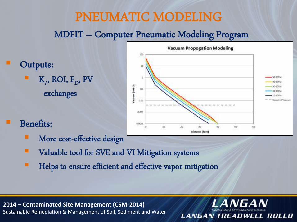
Outputs:
Ki , ROI, FD, PV
exchanges
Benefits:
More cost-effective design
Valuable tool for SVE and VI Mitigation systems
Helps to ensure efficient and effective vapor mitigation
PNEUMATIC MODELING MDFIT – Computer Pneumatic Modeling Program

2014 – Contaminated Site Management (CSM-2014) Sustainable Remediation & Management of Soil, Sediment and Water
Existing Vapor Recovery Well Network
Process Equipment:
• Blower
• AMS
• Control panel/Instrumentation and auto-dialer
• VGAC
SYSTEM DESIGN
DESIGN AIR FLOW RATE = 200 SCFM AT 80 IWC WELLHEAD VACUUM

2014 – Contaminated Site Management (CSM-2014) Sustainable Remediation & Management of Soil, Sediment and Water
FULL-SCALE RESULTS SSDS was meeting the required minimum sub-slab vacuum of 0.004
inches of water column (as recommended by USEPA)
SVE and SSDS can be implemented efficiently and cost effectively, even at complex sites, if we understand and consider the constraints of the site when designing the system. Importance of pilot testing and pneumatic modeling when designing/installing a SVE / SSDS at complex sites
SVE Mass Removal Rate =
1.25 lbs VOC / day

2014 – Contaminated Site Management (CSM-2014) Sustainable Remediation & Management of Soil, Sediment and Water
CASE STUDY – WAYNE, NEW JERSEY

2014 – Contaminated Site Management (CSM-2014) Sustainable Remediation & Management of Soil, Sediment and Water
SYSTEM IMPLEMENTATION – MARCH 2013
Design air flow rate = 500 scfm
Design wellhead vacuum = 35 IWC
Remote telemetry system
Operational sub-slab vacuums >> 0.004 IWC
Initial VOC mass removal rate = 0.25 lbs./day
Design and Operational Key Features:
2014 – Contaminated Site Management (CSM-2014) Sustainable Remediation & Management of Soil, Sediment and Water
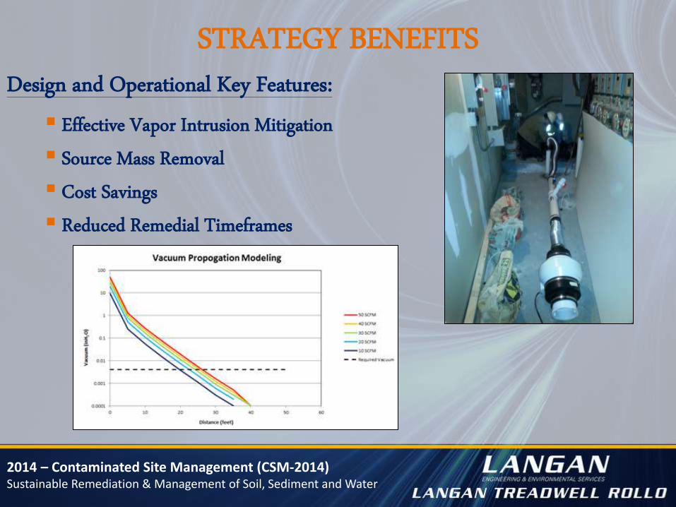
STRATEGY BENEFITS
Effective Vapor Intrusion Mitigation
Source Mass Removal
Cost Savings
Reduced Remedial Timeframes
Design and Operational Key Features:

2014 – Contaminated Site Management (CSM-2014) Sustainable Remediation & Management of Soil, Sediment and Water
LESSONS LEARNED Importance of pilot testing and pneumatic modeling when designing/installing an
SVE/SSDS at complex sites
If designed correctly, SVE and SSDS can be implemented efficiently and cost effectively,
even at complex sites.
Integrated SVE and VM Approach – Effective Optimization Strategy
Effective Vapor Intrusion Mitigation
Source Mass Removal
Benefits:
Cost Savings
Reduced Remedial Timeframes
2014 – Contaminated Site Management (CSM-2014) Sustainable Remediation & Management of Soil, Sediment and Water
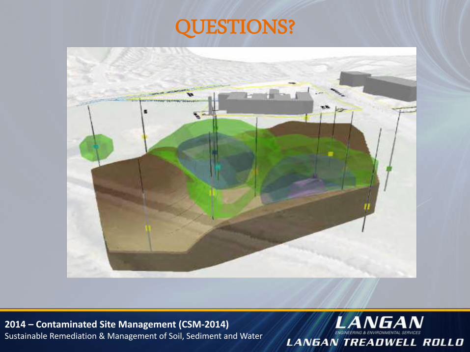
QUESTIONS?