cswip 3.2 latest wis10-mar-2011
TRANSCRIPT

7/22/2019 CSWIP 3.2 LATEST WIS10-Mar-2011
http://slidepdf.com/reader/full/cswip-32-latest-wis10-mar-2011 1/303
CSWIP 3.2 - Senior Welding Inspector -Level 3
WIS10
Training & Examination Services
Granta Park, Great AbingtonCambridge CB21 6AL, UK
Copyright © TWI Ltd
7/22/2019 CSWIP 3.2 LATEST WIS10-Mar-2011
http://slidepdf.com/reader/full/cswip-32-latest-wis10-mar-2011 2/303
Rev 1 January 2011Contents
Copyright TWI Ltd 2011
www.twitraining.com
CSWIP 3.2 - Senior Welding Inspector -Level 3
Contents
Section Subject
1 Duties of the Senior Welding Inspector
2 Terms and Definitions
3 Planning
4 Codes and Standards
5 Calibration of Welding Equipment
6 Destructive Testing
7 Heat Treatment
8 WPS and Welder Qualifications
9 Materials Inspection
10 Residual Stress and Distortion
11 Weldability of Steels12 Weld Fractures
13 Welding Symbols
14 NDT
15 Welding Consumables
16 MAG Welding
17 MMA Welding
18 Submerged Arc Welding
19 TIG Welding
20 Weld Imperfections
21 Weld Repairs
22 Arc Welding Safety
23 Appendices
24 Further Reading

7/22/2019 CSWIP 3.2 LATEST WIS10-Mar-2011
http://slidepdf.com/reader/full/cswip-32-latest-wis10-mar-2011 3/303
Section 1
Duties of theSenior Welding Inspector

7/22/2019 CSWIP 3.2 LATEST WIS10-Mar-2011
http://slidepdf.com/reader/full/cswip-32-latest-wis10-mar-2011 4/303
Rev 1 January 2011Duties of the Senior Welding Inspector
Copyright TWI Ltd 2011
www.twitraining.com 1-1
1 Duties of the Senior Welding Inspector
1.1 General
The Senior Welding Inspector has primarily a supervisory/managerial role,which could encompass the management and control of an inspectioncontract. The role would certainly include leading a team of WeldingInspectors, who will look to the Senior Welding Inspector for guidance,especially on technical subjects. The Senior Welding Inspector will beexpected to give advice, resolve problems, take decisions and generallylead from the front, sometimes in difficult situations.
The attributes required by the Senior Welding Inspector are varied and theemphasis on certain attributes and skills may differ from project to project.Essentially though the Senior Welding Inspector will require leadershipskills, technical skills and experience.
1.2 Leadership skills
Some aspects on the theory of leadership may be taught in the classroom,but leadership is an inherent part of the character and temperament of anindividual. Practical application and experience play a major part in thedevelopment of leadership skills and the Senior Welding Inspector shouldstrive to improve and fine tune these skills at every opportunity.
The skills required for the development of leadership include a:
Willingness and ability to accept instructions or orders from senior staffand to act in the manner prescribed.
Willingness and ability to give orders in a clear and concise manner,whether verbal or written, which will leave the recipient in no doubt as towhat action or actions are required.
Willingness to take responsibility, particularly when things go wrong,perhaps due to the Senior Welding Inspector’s direction, or lack of it.
Capacity to listen (the basis for good communication skills) if and whenexplanations are necessary and to provide constructive reasoning andadvice.
Willingness to delegate responsibility to allow staff to get on with the job
and to trust them to act in a professional manner. The Senior WeldingInspector should, wherever possible, stay in the background, managing.
Willingness and ability to support members of the team on technical andadministrative issues.

7/22/2019 CSWIP 3.2 LATEST WIS10-Mar-2011
http://slidepdf.com/reader/full/cswip-32-latest-wis10-mar-2011 5/303
Rev 1 January 2011Duties of the Senior Welding Inspector
Copyright TWI Ltd 2011
www.twitraining.com 1-2
1.3 Technical skills
A number of factors make up the technical skills required by the SeniorWelding Inspector and these are a knowledge of:
Technology. Normative documents.
Planning.
Organisation.
Auditing.
1.4 Knowledge of technology
Welding technology knowledge required by the Senior Welding Inspector isvery similar to that required by the Welding Inspector, but with someadditional scope and depth.
Certain areas where additional knowledge is required are a:
Knowledge of quality assurance and quality control.
Sound appreciation of the four commonly used non-destructive testingmethods.
Basic understanding of steel metallurgy for commonly welded materialsand the application of this understanding to the assessment of fracturesurfaces.
Assessment of non-destructive test reports, particularly the interpretationof radiographs.
1.5 Knowledge of normative documents
It is not a requirement for Inspectors at any level to memorise the content ofrelevant normative documents, except possibly with the exception of takingexaminations.
Specified normative documents (specifications, standards, codes ofpractice, etc) should be available at the workplace and the Senior WeldingInspector would be expected to read, understand and apply therequirements with the necessary level of precision and direction required.
The Senior Welding Inspector should be aware of the more widely usedstandards as applied in welding and fabrication. For example:
BS EN ISO 15614 / ASME IX Standards for welding procedureapproval
BS 4872, BS EN 287 / ASME IX Standards for welder approval.
PED BS 5500 / ASME VIII Standards for quality of fabrication.
BS EN ISO 9000 – 2000 Standards for quality management.

7/22/2019 CSWIP 3.2 LATEST WIS10-Mar-2011
http://slidepdf.com/reader/full/cswip-32-latest-wis10-mar-2011 6/303
Rev 1 January 2011Duties of the Senior Welding Inspector
Copyright TWI Ltd 2011
www.twitraining.com 1-3
1.6 Knowledge of planning
Any project or contract will require some planning if inspection is to becarried out effectively and within budget.
See Section: Planning for more detailed information.
1.7 Knowledge of organisation
The Senior Welding Inspector must have good organisational skills in orderto ensure that the inspection requirements of any quality/inspection plan canbe met, within the allocated time, budget and using the most suitablepersonnel for the activity. Assessment of suitable personnel may requireconsideration of their technical, physical and mental abilities in order toensure that they are able to perform the tasks required of them. Otherconsiderations would include availability of inspection personnel at the timerequired, levels of supervision and the monitoring of the inspector’s activitiesform start to contract completion.
1.8 Knowledge of quality/auditing
There are many situations in manufacturing or on a project where the SeniorWelding Inspector may be required to carry out audits.
See section on: Quality Assurance/Quality Control and Inspection formore detailed information.
1.9 Man management
As mentioned above, the Senior Welding Inspector will have to direct andwork with a team of Inspection personnel which he may well have to pick.He will have to liaise with customer representatives, sub-contractors andthird party Inspectors. He may have to investigate non-compliances, dealwith matters of discipline as well as personal matters of his staff.
To do this effectively he needs skills in man management.
1.10 Recruitment
When recruiting an individual or a team the SWI will first have to establishthe requirements of the work. Among them would be:
What skills are definitely required for the work and what additional oneswould be desirable?
Are particular qualifications needed?
Is experience of similar work desirable?
What physical attributes are needed?
Is the work local, in-shop, on-site, in a third world country?
Does the job require working unsociable hours being away from homefor long periods?
7/22/2019 CSWIP 3.2 LATEST WIS10-Mar-2011
http://slidepdf.com/reader/full/cswip-32-latest-wis10-mar-2011 7/303
Rev 1 January 2011Duties of the Senior Welding Inspector
Copyright TWI Ltd 2011
www.twitraining.com 1-4
Is the job for permanent staff or for a fixed term?
If overseas what are the leave and travel arrangements?
What is the likely salary?
During subsequent interviews the SWI will need to assess other aspects of
the candidates’ suitability:
Has he the ability to work on his own initiative?
Can he work as part of a team?
If overseas has the person been to a similar location?
What is his marital/home situation?
Are there any Passport/Visa problems likely?
1.11 Morale and motivation
The morale of a workforce has a significant effect on its performance so the
SWI must strive to keep the personnel happy and motivated and be able todetect signs of low morale.
Low morale can lead to among other things, poor productivity, less goodworkmanship, lack of diligence, taking short cuts, ignoring safety proceduresand higher levels of absenteeism.
The SWI needs to be able to recognise these signs and others such aspersonnel not starting work promptly, taking longer breaks, talking in groupsand grumbling about minor matters.
A good supervisor should not allow his workforce to get into such a state.
He must keep them motivated by:
His own demeanour – does he have drive and enthusiasm or is heseen to have no energy and generally depressed. The workforce willreact accordingly.
Is he seen to be leading from the front in a fair and consistent manner?
Favouritism in the treatment of staff, on disciplinary matters, theallocation of work, allotment of overtime, weekend working and
holidays are common causes of problems. Keep them informed in all aspects of the job and their situation.
Rumours of impending redundancies or cuts in allowances etc will notmake for good morale.
1.12 Discipline
Any workforce must be working in a disciplined manner, normally to rulesand standards laid down in the Company’s conditions of employment orrelevant company handbook. The SWI must have a good understanding ofthese requirements and be able to apply them in a fair and equitable
manner.
7/22/2019 CSWIP 3.2 LATEST WIS10-Mar-2011
http://slidepdf.com/reader/full/cswip-32-latest-wis10-mar-2011 8/303
Rev 1 January 2011Duties of the Senior Welding Inspector
Copyright TWI Ltd 2011
www.twitraining.com 1-5
He must have a clear understanding as to the limits of his authority –knowing how far he can go in disciplinary proceedings.
The usual stages of disciplinary procedure are:
The quiet word. Formal verbal warning.
Written warning.
Possible demotion, transfer, suspension.
Dismissal with notice.
Instant dismissal.
Usually after the written warning stage the matter will be handled by theCompany’s Personnel or Human Resources Department.
It is of vital importance that the company rules are rigorously followed asany deviation could result in claims for unfair or constructive dismissal.
In dealing with disciplinary matters the SWI must:
Act promptly.
Mean what he says.
Treat everyone fairly and as an adult.
Avoid constant complaining on petty issues.
Where there are serious breaches of company rules by one or two people
the rest of the workforce should be informed of the matter so that rumourand counter-rumours can be quashed.
Some matters of discipline may well arise because of incorrect workingpractices, passing off below quality work, signing for work which has notbeen done, etc.
In all such cases the SWI will need to carry out an investigation and applydisciplinary sanctions to the personnel involved. To do this:
First establish the facts – by interviewing staff, from the relevant
records, by having rechecks on part of the job. If any suspicions are confirmed, transfer/remove suspect personnel
from the job pending disciplinary proceedings. If the personnel areemployed by a sub-contractor then a meeting with the sub-contractorwill be needed to achieve the same end.
Find out the extent of the problem, is it localised or widespread?
Is there need to inform the customer and third party inspector?
Formulate a plan of action, with other company departments wherenecessary, to retrieve the situation.
Carry out the necessary disciplinary measures on the personnel
involved.

7/22/2019 CSWIP 3.2 LATEST WIS10-Mar-2011
http://slidepdf.com/reader/full/cswip-32-latest-wis10-mar-2011 9/303
Rev 1 January 2011Duties of the Senior Welding Inspector
Copyright TWI Ltd 2011
www.twitraining.com 1-6
Convene a meeting with the rest of the workforce to inform them of thesituation and ensure that any similar lapses will be dealt with severely.
Follow up the meeting with a written memo.
1.13 Summary
The Senior Welding Inspector’s role can be varied and complex, a numberof skills need to be developed in order for the individual to be effective in therole. Every Senior Welding Inspector will have personal skills and attributeswhich can be brought to the job, some of the skills identified above mayalready have been mastered or understood. The important thing for theindividual to recognise is not only do they have unique abilities which theycan bring to the role, but they also need to strive to be the best they can bystrengthening identifiable weak areas in their knowledge and understanding.Some ways in which these goals may be achieved is through:
Embracing facts and realities. Being creative.
Being interested in solving problems.
Being pro-active not reactive.
Having empathy with other people.
Having personal values.
Being objective.

7/22/2019 CSWIP 3.2 LATEST WIS10-Mar-2011
http://slidepdf.com/reader/full/cswip-32-latest-wis10-mar-2011 10/303
Section 2
Terms and Definitions

7/22/2019 CSWIP 3.2 LATEST WIS10-Mar-2011
http://slidepdf.com/reader/full/cswip-32-latest-wis10-mar-2011 11/303
Rev 1 January 2011Terms and Definitions
Copyright TWI Ltd 2011
www.twitraining.com 2-1
2 Terms and Definitions
Note The following definitions are taken from BS 499-1:1991 Welding terms andsymbols – Glossary for welding, brazing and thermal cutting
Welding An operation in which two or more parts are united by means of heat,pressure or both, in such a way that there is continuity in the nature of themetal between these parts.
Brazing A process of joining generally applied to metals in which, during or afterheating, molten filler metal is drawn into or retained in the space betweenclosely adjacent surfaces of the parts to be joined by capillary attraction. In
general, the melting point of the filler metal is above 450C but always below
the melting temperature of the parent material.
Braze weldingThe joining of metals using a technique similar to fusion welding and a fillermetal with a lower melting point than the parent metal, but neither usingcapillary action as in brazing nor intentionally melting the parent metal.
Weld A union of pieces of metal made by welding.
Joint
Connection where the individual components, suitably prepared andassembled, are joined by welding or brazing.

7/22/2019 CSWIP 3.2 LATEST WIS10-Mar-2011
http://slidepdf.com/reader/full/cswip-32-latest-wis10-mar-2011 12/303
Rev 1 January 2011Terms and Definitions
Copyright TWI Ltd 2011
www.twitraining.com 2-2
Type of joint Sketch Definition
Butt joint A connection between the endsor edges of two parts making an
angle to one another of 135-180 inclusive in the region of the joint
T joint A connection between the end oredge of one part and the face ofthe other part, the parts makingan angle to one another of more
than 5 up to and including 90 inthe region of the joint
Corner joint A connection between the endsor edges of two parts making anangle to one another of more
than 30 but less than 135 in theregion of the joint
Edge joint A connection between the edgesof two parts making an angle to
one another of 0-30 inclusive in
the region of the joint
Cruciform joint A connection in which two flatplates or two bars are welded toanother flat plate at right anglesand on the same axis
Lap joint A connection between two over-lapping parts making an angle to
one another of 0-5 inclusive inthe region of the weld or welds

7/22/2019 CSWIP 3.2 LATEST WIS10-Mar-2011
http://slidepdf.com/reader/full/cswip-32-latest-wis10-mar-2011 13/303
Rev 1 January 2011Terms and Definitions
Copyright TWI Ltd 2011
www.twitraining.com 2-3
2.1 Types of Welds
2.1.1 From configuration point of view
Butt weld Fillet weld
Autogenous weld A fusion weld made without filler metal. Can be achieved by TIG, plasmaelectron beam, laser or oxyfuel gas welding.
Slot weld A joint between two overlapping components made by depositing a filletweld round the periphery of a hole in one component so as to join it to thesurface of the other component exposed through the hole.
Butt weld
In a butt oint
In a T oint
In a corner oint

7/22/2019 CSWIP 3.2 LATEST WIS10-Mar-2011
http://slidepdf.com/reader/full/cswip-32-latest-wis10-mar-2011 14/303
Rev 1 January 2011Terms and Definitions
Copyright TWI Ltd 2011
www.twitraining.com 2-4
Plug weld A weld made by filling a hole in one component of a workpiece with fillermetal so as to join it to the surface of an overlapping component exposedthrough the hole (the hole can be circular or oval).
2.1.2 From the penetration point of view
Full penetration weld A welded joint where the weld metal fully penetrates the joint with completeroot fusion. In US the preferred term is complete joint penetration weld or
CJP for short (see AWS D1.1.)
Partial penetration weld A welded joint without full penetration. In US the preferred term is partial joint penetration weld or PJP for short.
2.2 Types of joint (see BS EN ISO 15607)
Homogeneous jointWelded joint in which the weld metal and parent material have no significantdifferences in mechanical properties and/or chemical composition. Example:two carbon steel plates welded with a matching carbon steel electrode.
Heterogeneous jointWelded joint in which the weld metal and parent material have significantdifferences in mechanical properties and/or chemical composition. Example:a repair weld of a cast iron item performed with a nickel base electrode.
Dissimilar jointWelded joint in which the parent materials have significant differences inmechanical properties and/or chemical composition. Example: a carbonsteel lifting lug welded onto an austenitic stainless steel pressure vessel.

7/22/2019 CSWIP 3.2 LATEST WIS10-Mar-2011
http://slidepdf.com/reader/full/cswip-32-latest-wis10-mar-2011 15/303
Rev 1 January 2011Terms and Definitions
Copyright TWI Ltd 2011
www.twitraining.com 2-5
2.3 Features of the completed weld
Parent metalMetal to be joined or surfaced by welding, braze welding or brazing.
Filler metalMetal added during welding, braze welding, brazing or surfacing.
Weld metal All metal melted during the making of a weld and retained in the weld.
Heat-affected zone (HAZ)The part of the parent metal that is metallurgically affected by the heat ofwelding or thermal cutting, but not melted.
Fusion line
Boundary between the weld metal and the HAZ in a fusion weld. This is anon-standard term for weld junction.
Weld zoneZone containing the weld metal and the HAZ.
Weld faceSurface of a fusion weld exposed on the side from which the weld has beenmade.
Root
Zone on the side of the first run farthest from the welder.
ToeBoundary between a weld face and the parent metal or between runs. Thisis a very important feature of a weld since toes are points of high stressconcentration and often they are initiation points for different types of cracks(eg fatigue cracks, cold cracks). In order to reduce the stress concentration,toes must blend smoothly into the parent metal surface.
Excess weld metalWeld metal lying outside the plane joining the toes. Other non-standard
terms for this feature: reinforcement, overfill.

7/22/2019 CSWIP 3.2 LATEST WIS10-Mar-2011
http://slidepdf.com/reader/full/cswip-32-latest-wis10-mar-2011 16/303
Rev 1 January 2011Terms and Definitions
Copyright TWI Ltd 2011
www.twitraining.com 2-6
Root
Parentmetal
Weldmetal
HAZ
Weldzone
Fusionline
Weldface Toe
Parent
metal
Excessweld metal
Excessweld metal
Butt weld
Fusionline
Weldmetal
Root
Parentmetal
HAZ
W eldzone
Weldface
Toe
Parentmetal
Excesswe ld metal
Fillet weld

7/22/2019 CSWIP 3.2 LATEST WIS10-Mar-2011
http://slidepdf.com/reader/full/cswip-32-latest-wis10-mar-2011 17/303
Rev 1 January 2011Terms and Definitions
Copyright TWI Ltd 2011
www.twitraining.com 2-7
2.4 Weld preparation
A preparation for making a connection where the individual components,suitably prepared and assembled, are joined by welding or brazing.
2.4.1 Features of the weld preparationAngle of bevelThe angle at which the edge of a component is prepared for making a weldin case of a V preparation for a MMA weld on carbon steel plates, this angle
is between 25-30. In the case of a U preparation for an MMA weld on
carbon steel plates, this angle is between 8-12. In case of a single bevelpreparation for an MMA weld on carbon steel plates, this angle is between
40-50. In case of a single J preparation for a MMA weld on carbon steel
plates, this angle is between 10-20.
Included angleThe angle between the planes of the fusion faces of parts to be welded. Inthe case of single V, single U, double V and double U this angle is twice thebevel angle. In case of single bevel, single J, double bevel and double J, theincluded angle is equal to the bevel angle.
Root faceThe portion of a fusion face at the root that is not bevelled or grooved. Itsvalue depends on the welding process used, parent material to be weldedand application; for a full penetration weld on carbon steel plates, it has avalue between 1-2mm (for the common welding processes).
GapThe minimum distance at any cross section between edges, ends orsurfaces to be joined. Its value depends on the welding process used andapplication; for a full penetration weld on carbon steel plates, it has a valuebetween 1-4mm.
Root radiusThe radius of the curved portion of the fusion face in a component preparedfor a single J, single U, double J or double U weld. In case of MMA,MIG/MAG and oxyfuel gas welding on carbon steel plates, the root radius
has a value of 6mm in case of single and double U preparations and 8mm incase of single and double J preparations.
LandThe straight portion of a fusion face between the root face and the curvedpart of a J or U preparation can be 0. Usually present in case of weldpreparations for MIG welding of aluminium alloys.

7/22/2019 CSWIP 3.2 LATEST WIS10-Mar-2011
http://slidepdf.com/reader/full/cswip-32-latest-wis10-mar-2011 18/303
Rev 1 January 2011Terms and Definitions
Copyright TWI Ltd 2011
www.twitraining.com 2-8
2.4.2 Types of preparation
Open square butt preparation
This preparation is used for welding thin components, either from one orboth sides. If the root gap is zero (ie if components are in contact), thispreparation becomes a closed square butt preparation (not recommendeddue to the lack of penetration problems!).
Single V preparation
The V preparation is one of the most common preparations used in welding;it can be produced using flame or plasma cutting (cheap and fast). Forthicker plates a double V preparation is preferred since it requires less fillermaterial to complete the joint and the residual stresses can be balanced onboth sides of the joint resulting in lower angular distortion.
Double V preparation
The depth of preparation can be the same on both sides (symmetric doubleV preparation) or deeper on one side (asymmetric double V preparation).Usually, in this situation the depth of preparation is distributed as 2/3 of the
thickness of the plate on the first side with the remaining 1/3 on the
Angle ofbevel
Included angle
Gap Root face

7/22/2019 CSWIP 3.2 LATEST WIS10-Mar-2011
http://slidepdf.com/reader/full/cswip-32-latest-wis10-mar-2011 19/303
Rev 1 January 2011Terms and Definitions
Copyright TWI Ltd 2011
www.twitraining.com 2-9
backside. This asymmetric preparation allows for a balanced weldingsequence with root back gouging, giving lower angular distortions. Whilstsingle V preparation allows welding from one side, double V preparationrequires both sides access (the same applies for all double sidepreparations).
Single U preparation
U preparation can be produced only by machining (slow and expensive).However, tighter tolerances obtained in this case provide for a better fit-upthan in the case of V preparations. Usually it is applied for thicker platescompared with single V preparation (requires less filler material to completethe joint and this lead to lower residual stresses and distortions). Similar withthe V preparation, in case of very thick sections a double U preparation canbe used.
Double U preparation
Usually this type does not require a land (exception: aluminium alloys).
GapLand
Included angle
Angle ofbevel
Root
radius
Rootface

7/22/2019 CSWIP 3.2 LATEST WIS10-Mar-2011
http://slidepdf.com/reader/full/cswip-32-latest-wis10-mar-2011 20/303
Rev 1 January 2011Terms and Definitions
Copyright TWI Ltd 2011
www.twitraining.com 2-10
Single V preparation with backing strip
Backing strips allow the production of full penetration welds with increasedcurrent and hence increased deposition rates/productivity without thedanger of burn-through. Backing strips can be permanent or temporary.Permanent types are of the same material being joined and are tack weldedin place. The main problems related with this type of weld are poor fatigueresistance and the probability of crevice corrosion between the parent metaland the backing strip. It is also difficult to examine by NDT due to the built-in
crevice at the root of the joint. Temporary types include copper strips,ceramic tiles and fluxes.
Single bevel preparation
Double bevel preparation

7/22/2019 CSWIP 3.2 LATEST WIS10-Mar-2011
http://slidepdf.com/reader/full/cswip-32-latest-wis10-mar-2011 21/303
Rev 1 January 2011Terms and Definitions
Copyright TWI Ltd 2011
www.twitraining.com 2-11
Single J preparation
Double J preparation
All these preparations (single/double bevel and single/double J) can be usedon T joints as well. Double preparations are recommended in case of thicksections. The main advantage of these preparations is that only onecomponent is prepared (cheap, can allow for small misalignments).
For further details regarding weld preparations, please refer to BS EN ISO9692 standard.
2.5 Size of butt welds
Full penetration butt weld
Actual throatthickness
Design throatthickness

7/22/2019 CSWIP 3.2 LATEST WIS10-Mar-2011
http://slidepdf.com/reader/full/cswip-32-latest-wis10-mar-2011 22/303
Rev 1 January 2011Terms and Definitions
Copyright TWI Ltd 2011
www.twitraining.com 2-12
Partial penetration butt weld
As a general rule:
Actual throat thickness = design throat thickness + excess weld metal.
Full penetration butt weld ground flush
Butt weld between two plates of different thickness
Run (pass)The metal melted or deposited during one passage of an electrode, torch orblowpipe.
Single run weld Multi run weld
Design throat thickness= thickness of thethinner plate
Actual throat thickness =maximum thicknessthrough the joint
Design throatthickness
Actual throatthickness
Actual throat thickness= design throat thickness

7/22/2019 CSWIP 3.2 LATEST WIS10-Mar-2011
http://slidepdf.com/reader/full/cswip-32-latest-wis10-mar-2011 23/303
Rev 1 January 2011Terms and Definitions
Copyright TWI Ltd 2011
www.twitraining.com 2-13
Layer A stratum of weld metal consisting of one or more runs.Types of butt weld (from accessibility point of view):
Single side weld Double side weld
2.6 Fillet weld
A fusion weld, other than a butt, edge or fusion spot weld, which isapproximately triangular in transverse cross section.
2.6.1 Size of fillet welds
Unlike butt welds, fillet welds can be defined using several dimensions.
Actual throat thickness The perpendicular distance between two lines, each parallel to a line joiningthe outer toes, one being a tangent at the weld face and the other beingthrough the furthermost point of fusion penetration.
Design throat thickness The minimum dimension of throat thickness used for purposes of design. Also known as effective throat thickness, symbolised on the drawing with a.
Leg length The distance from the actual or projected intersection of the fusion facesand the toe of a fillet weld, measured across the fusion face, symbolised onthe drawing with z.
Leg length
Actual throat thickness
Design throat thickness
Leg length

7/22/2019 CSWIP 3.2 LATEST WIS10-Mar-2011
http://slidepdf.com/reader/full/cswip-32-latest-wis10-mar-2011 24/303
Rev 1 January 2011Terms and Definitions
Copyright TWI Ltd 2011
www.twitraining.com 2-14
2.6.2 Shape of fillet welds
Mitre fillet weldFlat face fillet weld in which the leg lengths are equal within the agreedtolerance. The cross section area of this type of weld is considered to be aright angle isosceles triangle with a design throat thickness a and a leglength z. The relation between design throat thickness and leg length is:
a = 0,707 z. or z = 1,41 a.
Convex fillet weldFillet weld in which the weld face is convex. The above relation between theleg length and the design throat thickness written in case of mitre fillet weldsis also valid for this type of weld. Since there is an excess weld metalpresent in this case, the actual throat thickness is bigger than the designthroat thickness.
Concave fillet weldFillet weld in which the weld face is concave. The above relation between
the leg length and the design throat thickness written in case of mitre filletwelds is not valid for this type of weld. Also, the design throat thickness isequal to the actual throat thickness. Due to the smooth blending betweenthe weld face and surrounding parent material, the stress concentrationeffect at the toes of the weld is reduced compared with the previous type.This is why this weld is highly desired in case of applications subjected tocyclic loads where fatigue phenomena might be a major cause for failure.

7/22/2019 CSWIP 3.2 LATEST WIS10-Mar-2011
http://slidepdf.com/reader/full/cswip-32-latest-wis10-mar-2011 25/303
Rev 1 January 2011Terms and Definitions
Copyright TWI Ltd 2011
www.twitraining.com 2-15
Asymmetrical fillet weldFillet weld in which the vertical leg length is not equal with the horizontal leglength. The relation between the leg length and the design throat thicknesswritten in case of mitre fillet welds is not valid for this type of weld becausethe cross section is not an isosceles triangle.
Throatsize
Verticalleg size
Horizontal
leg size
Deep penetration fillet weldFillet weld with a deeper than normal penetration. It is produced using highheat input welding processes (ie SAW or MAG with spray transfer). Thistype of weld uses the benefits of greater arc penetration to obtain therequired throat thickness whilst reducing the amount of deposited metalneeded, thus leading to a reduction in residual stress level. In order toproduce a consistent and constant penetration, the travel speed must be
kept constant, at a high value. As a consequence, this type of weld isusually produced using mechanised or automatic welding processes. Also,the high depth-to-width ratio increases the probability of solidificationcentreline cracking. In order to differentiate this type of welds from theprevious types, the throat thickness is symbolised with s instead of a.

7/22/2019 CSWIP 3.2 LATEST WIS10-Mar-2011
http://slidepdf.com/reader/full/cswip-32-latest-wis10-mar-2011 26/303
Rev 1 January 2011Terms and Definitions
Copyright TWI Ltd 2011
www.twitraining.com 2-16
2.6.3 Compound of butt and fillet welds
A combination of butt and fillet welds used in case of T joints with full orpartial penetration or butt joints between two plates with different thickness.Fillet welds added on top of the groove welds improve the blending of weldface towards parent metal surface and reduce the stress concentration atthe toes of the weld.
2.7 Welding position, weld slope and weld rotation
Weld positionThe orientation of a weld expressed in terms of working position, weld slopeand weld rotation (for further details, please see ISO 6947).
Weld slopeThe angle between root line and the positive X axis of the horizontalreference plane, measured in mathematically positive direction (ie counter-clockwise).
Weld rotationThe angle between the centreline of the weld and the positive Z axis or a
line parallel to the Y axis, measured in the mathematically positive direction(ie counter-clockwise) in the plane of the transverse cross section of theweld in question.
Double bevel compound weld
Filletweld
Bevelweld

7/22/2019 CSWIP 3.2 LATEST WIS10-Mar-2011
http://slidepdf.com/reader/full/cswip-32-latest-wis10-mar-2011 27/303
Rev 1 January 2011Terms and Definitions
Copyright TWI Ltd 2011
www.twitraining.com 2-17
Welding position Sketch Definition
Flat A welding position in whichthe welding is horizontal,with the centreline ofthe weld vertical. Symbol
according ISO 6947 – PA.Horizontal-vertical A welding position in which
the welding is horizontal(applicable in case of filletwelds). Symbol accordingISO 6947 – PB
Horizontal A welding position in whichthe welding is horizontal,with the centreline of theweld horizontal. Symbolaccording ISO 6947 – PC
Vertical up A welding position in whichthe welding is upwards.
Symbol according ISO 6947 – PF.
Vertical down A welding position in whichthe welding is downwards.Symbol according ISO 6947 – PG
Overhead A welding position in whichthe welding is horizontal andoverhead, with the centre-line of the weld vertical.Symbol according ISO 6947 – PE.
Horizontal-overhead
A welding position in whichthe welding is horizontal andoverhead (applicable incase of fillet welds). Symbolaccording ISO 6947 – PD.
PF
PG

7/22/2019 CSWIP 3.2 LATEST WIS10-Mar-2011
http://slidepdf.com/reader/full/cswip-32-latest-wis10-mar-2011 28/303
Rev 1 January 2011Terms and Definitions
Copyright TWI Ltd 2011
www.twitraining.com 2-18
Tolerances for the welding positions.
2.8 Weaving
Transverse oscillation of an electrode or blowpipe nozzle during thedeposition of weld metal. This technique is generally used for vertical upwelds.
Stringer bead A run of weld metal made with little or no weaving motion.

7/22/2019 CSWIP 3.2 LATEST WIS10-Mar-2011
http://slidepdf.com/reader/full/cswip-32-latest-wis10-mar-2011 29/303
Section 3
Planning
7/22/2019 CSWIP 3.2 LATEST WIS10-Mar-2011
http://slidepdf.com/reader/full/cswip-32-latest-wis10-mar-2011 30/303
Rev 1 January 2011Planning
Copyright TWI Ltd 2011
www.twitraining.com 3-1
3 Planning
3.1 General
The Senior Welding Inspector is usually involved in planning for inspectionat one or more of the following stages of a project:
Pre-contract Identification of the job requirements, recruiting and allocating suitablytrained and qualified staff, gathering together relevant normativedocuments, technical data and drawings, producing work/inspectionschedules and quality plans as well as general administration.
In-contract Application of inspection methodologies to the requirements of thecontract specification, production and collection of inspection and testreports/documentation.
Post-contract Compilation of inspection reports, certification and test data.
There are a number of methods of planning for inspection activities, themethod selected being dependant on a number of factors, primarily therequirements of the client and the specific project.
The various methods are:
In-situ inspection; an inspector(s) placed permanently at the work place. Theinspector would be expected to work independently, responsible for using
the allocated inspection time in a useful and expedient manner. Periodicvisits to the work place would be made by the Senior Inspector.
3.2 Gantt charts
Gantt charts define stages of production and estimated work time for eachstage.
A Gantt chart is a popular type of bar chart/graph that illustrates a projectschedule ie list of a project's terminal elements. Terminal elements comprisethe work breakdown structure (WBS) of the project and are the lowestactivity or deliverable, with intended start and finish dates. Terminalelements are not further subdivided.
Terminal elements are the items that are estimated in terms of resourcerequirements, budget and duration linked by dependencies and schedules.
An example of a typical Gantt chart that could be used to plan inspectionactivities for either manufacturing or construction is shown below.
The WBS/task elements are listed on the left hand side and the start andcompletion of each activity is represented by a bar to the right of the activity.

7/22/2019 CSWIP 3.2 LATEST WIS10-Mar-2011
http://slidepdf.com/reader/full/cswip-32-latest-wis10-mar-2011 31/303
Rev 1 January 2011Planning
Copyright TWI Ltd 2011
www.twitraining.com 3-2
The time period in this example is represented in months, both planned andactual. Some Gantt charts may show time in weeks, which can also bebroken down into days.
Example of a Gantt chart
Any Project Phase 1 Inspection Schedule
Workbreakdownstructure
(WBS)
2011
January February March April May June
Recruit andallocateinspection staff
Reviewfabricationdrawings
Review WPSs,WPQRsandWATCs
Witness and testWPSs, WPQRs
Witness welderqualificationtests
Prepare qualityplans
Visualinspection offirstproduction
welds
Legend
Planned duration
Actual duration
Planned milestone
Actual milestone
7/22/2019 CSWIP 3.2 LATEST WIS10-Mar-2011
http://slidepdf.com/reader/full/cswip-32-latest-wis10-mar-2011 32/303
Rev 1 January 2011Planning
Copyright TWI Ltd 2011
www.twitraining.com 3-3
3.3 Critical path analysis (CPA)
Critical path analysis (CPA) is a powerful project management tool thathelps to schedule and manage complex projects. Developed in the 1950s tocontrol large defence projects, CPA has been used routinely since then. As
with Gantt charts, CPA helps plan all tasks that must be completed as partof a project. They act as the basis both for preparation of a schedule and ofresource planning. During management of a project, they allow monitoringof achievement of project goals.
CPA can also show where remedial action needs to be taken in order to geta project back on course.
The benefit of using CPA over Gantt charts is that CPA formally identifiestasks which must be completed on time in order for the whole project to becompleted on time and also identifies which tasks can be delayed for a while
if resources need to be reallocated to catch up on missed tasks.
A further benefit of CPA is that it helps to identify the minimum length of timeneeded to complete a project. Where there is a need to run an acceleratedproject, fast track, it helps to identify which project steps should beaccelerated in order to complete the project within the available time. Thishelps to minimise cost while still achieving objectives.
The disadvantage of CPA is that the relation of tasks to time is not asimmediately obvious as with Gantt charts. This can make them more difficultto understand for someone who is not familiar with the technique.
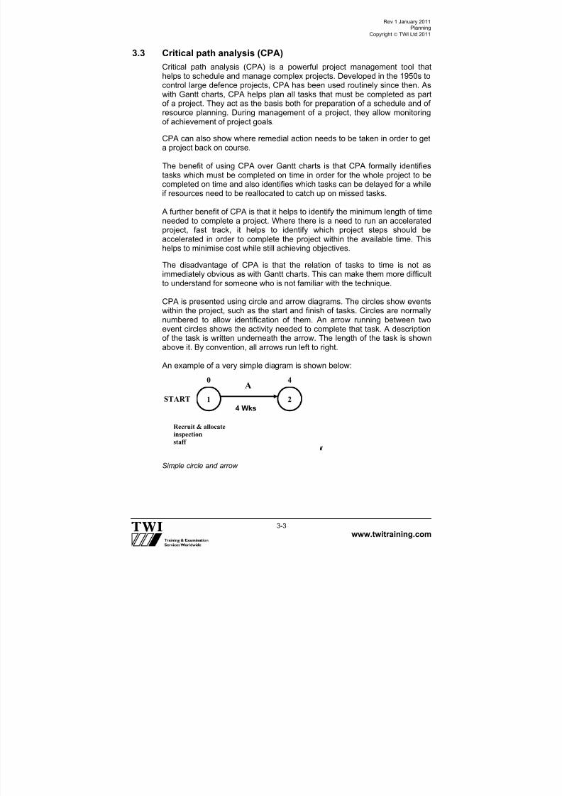
CPA is presented using circle and arrow diagrams. The circles show eventswithin the project, such as the start and finish of tasks. Circles are normallynumbered to allow identification of them. An arrow running between twoevent circles shows the activity needed to complete that task. A descriptionof the task is written underneath the arrow. The length of the task is shownabove it. By convention, all arrows run left to right.
An example of a very simple diagram is shown below:
Simple circle and arrow
1 24 Wks
Recruit & allocate
inspection
staffSimple Circle and Arrow
0 4A
START

7/22/2019 CSWIP 3.2 LATEST WIS10-Mar-2011
http://slidepdf.com/reader/full/cswip-32-latest-wis10-mar-2011 33/303
Rev 1 January 2011Planning
Copyright TWI Ltd 2011
www.twitraining.com 3-4
This shows the start event (circle 1) and the completion of the recruit andallocate inspection staff task (circle 2). The arrow between the two circlesshows the activity of carrying out recruit and allocates inspection staff. Thetime allocated for this activity is 4 weeks.
In the example above, the numbers above the circles show the earliestpossible time that this stage of the project will be reached.
Where one activity cannot start until another has been completed and whenother activities need to be scheduled it is useful to tabulate the terminalelements and allocate time against each activity. For example the inspectionactivities for a project could be shown as:
IdentificationTerminalelement/activity
Scheduledcompletion
Timeallocated
A
Recruit and allocate
inspection staff
To be completed first
4 weeks
B
Review fabricationdrawings, materialand consumablecertificates
Start when A iscompleted
2 weeks
CReview WPS’s,WPQR’s andWATC’s
Start when A iscompleted 2 weeks
D
Prepare quality plansand identifyinspectionrequirements
Start when B iscompleted
3 weeks
EWitness and testWPS’s andWPQRS’s
Start when C iscompleted 2 weeks
FWitness welderqualification tests
Start when C, D andE are completed
2 weeks
GVisual inspection andtesting of productionwelds
Start when F iscompleted 9 weeks
Total time allocated 24 weeks
The above tabulated terminal elements can now be shown as an algorithm,see the following example

7/22/2019 CSWIP 3.2 LATEST WIS10-Mar-2011
http://slidepdf.com/reader/full/cswip-32-latest-wis10-mar-2011 34/303
3-5
Critical path analysis for example inspection project.
Start 1 2 3 5 6
4
A B D
CE
F
4 wks 2 wks 3 wks 2 wks
2wks
2wks0 4 6
6
11 13

7/22/2019 CSWIP 3.2 LATEST WIS10-Mar-2011
http://slidepdf.com/reader/full/cswip-32-latest-wis10-mar-2011 35/303

7/22/2019 CSWIP 3.2 LATEST WIS10-Mar-2011
http://slidepdf.com/reader/full/cswip-32-latest-wis10-mar-2011 36/303
Rev 1 January 2011Planning
Copyright TWI Ltd 2011
www.twitraining.com 3-7
3.5 Summary
The Senior Welding Inspector doe not need to have an in-depth knowledgeof planning and would not be responsible for the planning of inspectionactivities on a large project or contract; this would be the responsibility of the
planning team or planning department.
However the SWI does need to have a basic understanding of projectplanning as inspection tasks must link in with other terminal activities toensure that inspection tasks are carried out on a timely and cost effectivebasis, in accordance with the planning system being used on a particularproject or contract.

7/22/2019 CSWIP 3.2 LATEST WIS10-Mar-2011
http://slidepdf.com/reader/full/cswip-32-latest-wis10-mar-2011 37/303
Section 4
Codes and Standards

7/22/2019 CSWIP 3.2 LATEST WIS10-Mar-2011
http://slidepdf.com/reader/full/cswip-32-latest-wis10-mar-2011 38/303
Rev 1 January 2011Codes and Standards
Copyright TWI Ltd 2011
www.twitraining.com 4-1
4 Codes and Standards
4.1 General
The control of quality in a fabrication and welding situation is achieved byworking to company procedures and codes of construction or standards.The latter may be international, national, company’s own or specific to theparticular client or contract.
Company procedures are usually covered in quality manuals the scope ofwhich may vary widely depending upon the size of company, its range ofwork, its working practices and many other factors.
4.2 Company manuals
4.2.1 Quality assurance manual
Quality assurance is defined in IS0 9000 as; part of quality managementfocused on providing confidence that quality requirements will be fulfilled.
Essentially what the QA manual sets out is how the company is organised,to lay down the responsibilities and authority of the various departments,how these departments interlink. The manual usually covers all aspects ofthe company structure, not just those aspects of manufacture.
4.2.2 Quality control manual
Quality control is defined in ISO 9000 as; part of quality managementfocused on fulfilling quality requirements.
The QC manual will be the manual most often referred to by the SWI as itwill spell out in detail how different departments and operations areorganised and controlled.
Typical examples would be: production and control of drawings, howmaterials and consumables are purchased, how welding procedures areproduced, etc.
Essentially all operations to be carried out within the organisation will havecontrol procedures laid down.
In particular it will lay down how the Inspection function, whether visual,dimensional or NDT, will be performed, inspection being defined as theactivity of measuring, examining and testing characteristics of a product orservice and comparing these to a specified requirement. Such requirementsare laid down in codes of practice and standards.

7/22/2019 CSWIP 3.2 LATEST WIS10-Mar-2011
http://slidepdf.com/reader/full/cswip-32-latest-wis10-mar-2011 39/303
Rev 1 January 2011Codes and Standards
Copyright TWI Ltd 2011
www.twitraining.com 4-2
4.3 Auditing
Auditing is a term originating from accountancy practice which involves anindependent accountant checking the accounts of a company to see if theaccounts are fair and accurate. A similar checking process is now widely
practised in manufacturing and construction industries and inspectionpersonnel will be involved in the carrying out of this operation.
Different types of audits may be performed:
Full audit of a company, usually carried out by a third party such as aCertifying Authority, checking the company for the award of a QAaccreditation system such as ISO 9000 or ASME stamp.
Major audit by a potential customer prior to placement of a largecontract. This is usually carried out to demonstrate the company has allthe necessary facilities, plant, machinery, personnel and quality systems
in place to enable them to successfully complete the contract. Part audits carried out as ongoing demonstration that the quality system
is working properly.
An example of the latter case would be where a Senior Inspector isresponsible for signing-off the data book or release certificate for a product. After checking that all the necessary documents are in the package and thatthey have been correctly completed and approved where necessary, theSWI would look at a part of the job – a beam, a piece of pipework etc andcrosscheck against the drawings, mill certificates, inspection reports etc thatall comply with the job requirements.
4.4 Codes and standards
It is not necessary for the Inspector to carry a wide range of codes andstandards in the performance of his/her duties. Normally the specification ormore precisely the contract specification is the only document required.However the contract specification may reference supporting codes andstandards and the inspector should know where to access these normativedocuments.
The following is a list of definitions relating to codes and standards which
the Inspector may come across whilst carrying inspection duties
4.4.1 Definitions
Normative document:Provides rules, guidelines or characteristics for activities or their results.
The term normative document is generic and covers documents such asstandards, technical specifications, codes of practice and regulations.*

7/22/2019 CSWIP 3.2 LATEST WIS10-Mar-2011
http://slidepdf.com/reader/full/cswip-32-latest-wis10-mar-2011 40/303
Rev 1 January 2011Codes and Standards
Copyright TWI Ltd 2011
www.twitraining.com 4-3
StandardDocument established by consensus and approved by a recognised body.
A standard provides, for common and repeated use, guidelines, rules, andcharacteristics for activities or their results, aimed at the achievement of the
optimum degree of order in a given context. *
Harmonised standards Standards on the same subject approved by different standardising bodies,that establish interchangeability of products, processes and services, ormutual understanding of test results or information provided according tothese standards*
Code of practice Document that recommends practices or procedures for the design,manufacture, installation, maintenance, utilisation of equipment, structures
or products.
A code of practice may be a standard, part of a standard or independent ofa standard.*
Regulation Document providing binding legislative rules that is adopted by anauthority.*
Authority Body (responsible for standards and regulations legal or administrativeentity that has specific tasks and composition) that has legal powers andrights.*
Regulatory authority Authority responsible for preparing or adopting regulations.*
Enforcement authority Authority responsible for enforcing regulations.*
Specification
Document stating requirements. Meaning full data and its supportingmedium stating needs or expectations that is stated, generally implied orobligatory.**
Procedure Specified way to carry out an activity or a process.* Usually it is a writtendescription of all essential parameters and precautions to be observed whenapplying a technique to a specific application following an establishedstandard, code or specification

7/22/2019 CSWIP 3.2 LATEST WIS10-Mar-2011
http://slidepdf.com/reader/full/cswip-32-latest-wis10-mar-2011 41/303
Rev 1 January 2011Codes and Standards
Copyright TWI Ltd 2011
www.twitraining.com 4-4
Instruction Written description of the precise steps to be followed based on anestablished procedure, standard, code or specification.
Quality plan
A document specifying which procedures and associated resources shall beapplied by whom and when to a specific project, product, process orcontract.*
* ISO IEC Guide 2 – Standardisation and related activities – General vocabulary.** EN ISO 9000 – 2000 – Quality management systems – Fundamentals andvocabulary.
4.5 Summary
Application of the requirements of the quality manuals, the standards andcodes of practice ensure that a structure or component will have anacceptable level of quality and be fit for the intended purpose.
Applying the requirements of a standard, code of practice or specificationcan be a problem for the inexperienced Inspector. Confidence in applyingthe requirements of one or all of these documents to a specific applicationonly comes with use over a period of time.
If in doubt the Inspector must always refer to a higher authority in order toavoid confusion and potential problems.

7/22/2019 CSWIP 3.2 LATEST WIS10-Mar-2011
http://slidepdf.com/reader/full/cswip-32-latest-wis10-mar-2011 42/303
Rev 1 January 2011Codes and Standards
Copyright TWI Ltd 2011
www.twitraining.com 4-5
BS No. Title
BS 499: Part 1 Glossary of welding terms.
BS 709 Methods of destructive testing fusion welded joints and weld
metal in steel. BS 1113 Specification for design and manufacture of water-tube steam
generating plant.
BS 1453 Specification for filler materials for gas welding.
BS 1821 Specification for class I oxy -acetylene welding of ferritic steelpipe work for carrying fluids.
BS 2493 Low alloy steel electrodes for MMA welding
BS 2633 Specification for class I arc welding of Ferritic steel pipe work forcarrying fluids.
BS 2640 Specification for class II oxy - acetylene welding of carbon steelpipe work
for carrying fluids. BS 2654 Specification for manufacture of vertical steel welded non-
refrigerated storage tanks with butt-welded shells for thepetroleum industry.
BS 2901 Part 3: Filler rods and wires for copper and copper alloys.
BS 2926 Specification for chromium & chromium-nickel steel electrodesfor MMA
BS 2926 Specification for chromium & chromium-nickel steel electrodesfor MMA
BS 3019 TIG welding.
BS 3604 Steel pipes and tubes for pressure purposes; Ferritic alloy steel
with specified elevated temperature properties for pressurepurposes.
BS 3605 Specification for seamless tubes.
BS 4515 Specification for welding of steel pipelines on land andoffshore.
BS 4570 Specification for fusion welding of steel castings.
BS 4677 Specification for arc welding of austenitic stainless steel pipework for carrying fluids.
BS 4872 Part 1: Approval testing of welders when procedure approval is notrequired. Fusion welding of steel.
BS 4872 Part 2: TIG or MIG welding of aluminium and its alloys.
BS 6323 Specification for seamless and welded steel tubes forautomobile, mechanical and general engineering purposes.
BS 6693 Method for determination of diffusible hydrogen in weld metal.
BS 6990 Code of practice for welding on steel pipes containing processfluids or their residues.
BS 7191 Specification for weldable structural steels for fixed offshorestructures.
BS 7570 Code of practice for validation of arc welding equipment.

7/22/2019 CSWIP 3.2 LATEST WIS10-Mar-2011
http://slidepdf.com/reader/full/cswip-32-latest-wis10-mar-2011 43/303
Rev 1 January 2011Codes and Standards
Copyright TWI Ltd 2011
www.twitraining.com 4-6
BS EN No Title
BS EN 287 Part 1: Qualification test of welders - Fusion welding - Steels.
BS EN 440 Wire electrodes and deposits for gas shielded metal arcof non-alloy and fine grain steels.
BS EN 499 Covered electrodes for manual metal arc welding of non–alloy and fine grain steels.
BS EN 3834-Parts 1 to 5
Quality requirements for fusion welding of metallicmaterials
BS EN 756 Wire electrodes and flux wire combinations for submergedarc welding of non-alloy and fine grain steels.
BS EN 760 Fluxes for submerged arc welding.
BS EN 970 Non-destructive examination of fusion welds - visualexamination.
BS EN 910 Destructive tests on welds in metallic materials - Bend tests.
BS EN 12072 Filler rods and wires for stainless steels.
BS EN ISO 18274 Aluminium and aluminium alloys & magnesium alloys. Nickel& nickel alloys.
Note: The Inspector should have an awareness of standards printed in bold.
BS EN NUMBER TITLE
BS EN 1011Part 1:Part 2:Part 3Part 4.
Welding recommendations for welding of metallic materialGeneral guidance for arc welding.Arc welding of ferritic steels. Arc welding of stainless steels Arc welding of aluminium and aluminium alloys.
EN 1320 Destructive tests on welds in metallic materials. EN 1435 Non-destructive examination of welds - Radiographic
examination of welded joints.
BS EN 10002 Tensile testing of metallic materials.
BS EN 10020 Definition and classification of grades of steel.
BS EN 10027 Designation systems for steels.
BS EN 10045 Charpy impact tests on metallic materials.
BS EN 10204 Metallic products - types of inspection documents.
BS EN 22553 Welded, brazed and soldered joints - symbolicrepresentation on drawings.
BS EN 24063 Welding, brazing, soldering and braze welding of metal.Nomenclature of processes and reference numbers forsymbolic representation on drawings.
BS EN 25817 Arc welded joints in steel. Guidance on quality levels forimperfections.
BS EN 26520 Classification of imperfections in metallic fusion welds,with explanations.
BS EN 26848 Specification for tungsten electrodes for inert gas shielded arcwelding and for plasma cutting and welding.

7/22/2019 CSWIP 3.2 LATEST WIS10-Mar-2011
http://slidepdf.com/reader/full/cswip-32-latest-wis10-mar-2011 44/303
Rev 1 January 2011Codes and Standards
Copyright TWI Ltd 2011
www.twitraining.com 4-7
ISO No Title
ISO 857 - 1 Welding and allied processes - Vocabulary - Part 1 -Metal welding processes.
ISO 6947 Welds - Working positions - definitions of angles of slopeand rotation.
ISO 9606 – 2 Qualification test of welders – fusion welding.Part 2 Aluminium & aluminium alloys.
ISO 15607 Specification and qualification of welding procedures formetallic materials - General rules.
ISO 15608 Welding - Guidelines for a metallic material grouping system.
ISO 15609 - 1 Specification and qualification of welding procedures formetallic materials - Welding procedure specification - Part 1:Arc welding.
ISO 15610 Specification and qualification of welding procedures for metallicmaterials- Qualification based on tested welding consumables.
ISO 15611 Specification and qualification of welding procedures for metallic
materials- Qualification based on previous welding experience.ISO 15613 Specification and qualification of welding procedures for metallic
materials - Qualification based on pre-production-welding test.
ISO 15614 Specification and qualification of welding procedures formetallic materials - Welding procedure test.
Part 1
Part 2Part 3Part 4Part 5
Part 6Part 7Part 8Part 9:Part 10Part 11Part 12Part 13
Arc and gas welding of steels and arc welding of nickel and nickelalloys. Arc welding of aluminium and its alloys*Welding procedure tests for the arc welding of cast irons*Finishing welding of aluminium castings* Arc welding of titanium, zirconium and their alloys.
Copper and copper alloys*Not usedWelding of tubes to tube-plate joints.Underwater hyperbaric wet welding*Hyperbaric dry welding*Electron and laser beam weldingSpot, seam and projection welding*Resistance butt and flash welding*
Note: The Inspector should have an awareness of standards printed in bold. *Proposed

7/22/2019 CSWIP 3.2 LATEST WIS10-Mar-2011
http://slidepdf.com/reader/full/cswip-32-latest-wis10-mar-2011 45/303
Section 5 Calibration of
Welding Equipment
7/22/2019 CSWIP 3.2 LATEST WIS10-Mar-2011
http://slidepdf.com/reader/full/cswip-32-latest-wis10-mar-2011 46/303
Rev 1 January 2011Calibration of Welding Equipment
Copyright TWI Ltd 2011
www.twitraining.com 5-1
5 Calibration of Welding Equipment
5.1 Introduction
BS 7570 - Code of practice for validation of arc welding equipment – astandard that gives guidance to:
Manufacturers about the accuracy required from output meters fitted towelding equipment to show welding current and voltage, etc.
End users who need to ensure that the output meters provide accuratereadings.
The Standard refers to two grades of equipment - standard and precisiongrade.
Standard grade equipment is suitable for manual and semi-automatic
welding processes.
Precision grade equipment is intended for mechanised or automatic weldingbecause there is usually a need for greater precision for all weldingvariables as well as the prospect of the equipment being used for higherduty cycle welding.
5.2 Terminology
BS 7570 defines the terms it uses such as:
CalibrationOperations for determining the magnitude of errors of a measuring instrument,etc.
ValidationOperations for demonstrating an item of welding equipment or weldingsystem conforms to the operating specification for that equipment or system.
AccuracyCloseness of an observed quantity to the defined, or true, value.
Thus, when considering welding equipment, those that have output metersfor welding parameters (current, voltage and travel speed, etc.) can becalibrated by checking the meter reading with a more accurate measuringdevice and adjusting the readings appropriately.
Equipment that does not have output meters (some power sources forMMA, MIG/MAG) cannot be calibrated but they can be validated, that is tomake checks to see that the controls are functioning properly.
7/22/2019 CSWIP 3.2 LATEST WIS10-Mar-2011
http://slidepdf.com/reader/full/cswip-32-latest-wis10-mar-2011 47/303
Rev 1 January 2011Calibration of Welding Equipment
Copyright TWI Ltd 2011
www.twitraining.com 5-2
5.3 Calibration frequency
BS 7570 recommends re-calibration/validation at:
Yearly intervals (following an initial consistency test at 3 monthly
intervals) for standard grade equipment. Six monthly intervals for precision grade equipment.
However, the Standard also recommends that re-calibration/validation maybe necessary more frequently. Factors to consider are:
Equipment manufacturer’s recommendations.
User’s requirements.
If the equipment has been repaired it should always be re-calibrated.
If there is reason to believe the performance of the equipment hasdeteriorated.
5.4 Instruments for calibration
Instruments used for calibration should:
Be calibrated by a recognised calibrator using standards traceable to anational standard.
Be at least twice and preferably five times, more accurate than theaccuracy required for the grade of equipment.
For precision grade equipment it will be necessary to use instrumentswith much greater precision for checking output meters.
5.5 Calibration methods
The Standard gives details about the characteristics of power source types,how many readings should be taken for each parameter and guidance onprecautions that may be necessary.
For the main welding parameters the Standard recommends:
Current Details are given about the instrumentation requirements and how to
measure pulsed current but there are requirements specified, orrecommendations made, about where in the circuit current measurementsshould be made. The implication is that current can be measured at anyposition in the circuit – the value should be the same.
Voltage The standard emphasises that for processes where voltage is pre-set (onconstant voltage the power sources) the connection points used for thevoltmeter incorporated into the power source may differ from the arcvoltage, which is the important parameter. To obtain an accurate measure ofarc voltage, the voltmeter should be positioned as near as practical to the
arc.

7/22/2019 CSWIP 3.2 LATEST WIS10-Mar-2011
http://slidepdf.com/reader/full/cswip-32-latest-wis10-mar-2011 48/303
Rev 1 January 2011Calibration of Welding Equipment
Copyright TWI Ltd 2011
www.twitraining.com 5-3
Power
Source
Wire Feeder
17
{arc voltage4
5
32
6
This is illustrated by the figure below which shows the power source voltagemeter connected across points 1 and 7.
An example of a welding circuit (for MIG/MAG).
However, because there will be some voltage drops in sections 1-2, 3-4 and6-7 due to connection points introducing extra resistance into the circuit, thevoltage meter reading on the power source will tend to give a higher readingthan the true arc voltage.
Even if the power source voltmeter is connected across points 3 and 7(which it may be) the meter reading would not take account of anysignificant voltage drops in the return cable - section 6-7.
The magnitude of any voltage drops in the welding circuit will depend oncable diameter, length and temperature and the Standard emphasises the
following:

7/22/2019 CSWIP 3.2 LATEST WIS10-Mar-2011
http://slidepdf.com/reader/full/cswip-32-latest-wis10-mar-2011 49/303
Rev 1 January 2011Calibration of Welding Equipment
Copyright TWI Ltd 2011
www.twitraining.com 5-4
It is desirable to measure the true arc voltage between points 4-5 but forsome welding processes it is not practical to measure arc voltage soclose to the arc.
For MMA, it is possible to take a voltage reading relatively close to the arcby connecting one terminal of the voltmeter through the cable sheath as
close as ~2m from the arc and connect the other terminal to theworkpiece (or to earth).
For MIG/MAG the nearest practical connection points have to be 3-5 buta change from an air-cooled to a water-cooled torch or vice-versa mayhave a significant effect on the measured voltage.
Voltage drops between points 5-6 will be insignificant if there is a goodconnection of the return cable at point 6.
The Standard gives guidance about minimising any drop in line voltage byensuring that:
The current return cable is as short as practical and is heavy, lowresistance, cable.
The current-return connector is suitably rated and firmly attached and sodoes not overheat due to high resistance.
The standard gives data for line voltage drops (DC voltage) according tocurrent, cable cross section and cable length (for both copper andaluminium cables).
Wire feed speed
For constant voltage (self-adjusting arc) processes such as MIG/MAG thestandard recognises that calibration of the wire feeder is generally notneeded because it is linked to current.
If calibration is required, it is recommended that the time be measured (inseconds) for ~1m of wire to be delivered (using a stopwatch or electronictimer).
The length of wire should then be measured (with a steel rule) to anaccuracy of 1mm and the feed speed calculated.
Travel speedWelding manipulators, such as rotators and robotic manipulators, as well asthe more conventional linear travel carriages, influence heat input and otherproperties of a weld and should be checked at intervals.
Most of the standard devices can be checked using a stopwatch andmeasuring rule, but more sophisticated equipment, such as a tacho-generator, may be appropriate.

7/22/2019 CSWIP 3.2 LATEST WIS10-Mar-2011
http://slidepdf.com/reader/full/cswip-32-latest-wis10-mar-2011 50/303
Section 6
Destructive Testing

7/22/2019 CSWIP 3.2 LATEST WIS10-Mar-2011
http://slidepdf.com/reader/full/cswip-32-latest-wis10-mar-2011 51/303
Rev 1 January 2011Destructive Testing
Copyright TWI Ltd 2011
www.twitraining.com 6-1
6 Destructive Testing
6.1 Introduction
European Welding Standards require test coupons that are made forwelding procedure qualification testing to be subjected to non-destructivetesting and then destructive testing.
The tests are called destructive tests because the welded joint is destroyedwhen various types of test piece are taken from it.
Destructive tests can be divided into 2 groups, those used to:
Measure a mechanical property – quantitative tests
Assess the joint quality – qualitative tests
Mechanical tests are quantitative because a quantity is measured – amechanical property such as tensile strength, hardness and impacttoughness.
Qualitative tests are used to verify that the joint is free from defects – theyare of sound quality - and examples of these are bend tests, macroscopicexamination and fracture tests (fillet fracture and nick-break).
6.2 Test types, test pieces and test objectives
Various types of mechanical tests are used by material manufacturers andsuppliers to verify that plates, pipes, forgings, etc. have the minimumproperty values specified for particular grades.
Design engineers use the minimum property values listed for particulargrades of material as the basis for design and the most cost-effectivedesigns are based on an assumption that welded joints have properties thatare no worse than those of the base metal.
The quantitative (mechanical) tests that are carried out for weldingprocedure qualification are intended to demonstrate that the joint propertiessatisfy design requirements.
The emphasis in the following sub-sections is on the destructive tests andtest methods that are widely used for welded joints.
6.2.1 Transverse tensile tests
Test objectiveWelding procedure qualification tests always require transverse tensile teststo show that the strength of the joint satisfies the design criterion.
Test specimens A transverse tensile test piece typical of the type specified by EuropeanWelding Standards is shown below.

7/22/2019 CSWIP 3.2 LATEST WIS10-Mar-2011
http://slidepdf.com/reader/full/cswip-32-latest-wis10-mar-2011 52/303
Rev 1 January 2011Destructive Testing
Copyright TWI Ltd 2011
www.twitraining.com 6-2
Standards, such as EN 895, that specify dimensions for transverse tensiletest pieces require all excess weld metal to be removed and the surface tobe free from scratches.
Test pieces may be machined to represent the full thickness of the joint but
for very thick joints it may be necessary to take several transverse tensiletest specimens to be able to test the full thickness.
Test methodTest specimens are accurately measured before testing. Specimens arethen fitted into the jaws of a tensile testing machine and subjected to acontinually increasing tensile force until the specimen fractures.
The tensile strength (Rm) is calculated by dividing the maximum load by thecross-sectional area of the test specimen - measured before testing.
The test is intended to measure the tensile strength of the joint andthereby show that the basis for design, the base metal properties, remainsthe valid criterion.
Acceptance criteriaIf the test piece breaks in the weld metal, it is acceptable provided thecalculated strength is not less than the minimum tensile strength specified,which is usually the minimum specified for the base metal material grade.
In the ASME IX code, if the test specimen breaks outside the weld or fusion
zone at a stress above 95% of the minimum base metal strength the testresult is acceptable.
6.2.2 All-weld tensile tests
Test objectiveThere may be occasions when it is necessary to measure the weld metalstrength as part of welding procedure qualification – particularly for elevatedtemperature designs.
The test is carried out in order to measure not only tensile strength but alsoyield (or proof strength) and tensile ductility.
Parallellength

7/22/2019 CSWIP 3.2 LATEST WIS10-Mar-2011
http://slidepdf.com/reader/full/cswip-32-latest-wis10-mar-2011 53/303
Rev 1 January 2011Destructive Testing
Copyright TWI Ltd 2011
www.twitraining.com 6-3
All weld tensile tests are also regularly carried out by welding consumablemanufacturers to verify that electrodes and filler wires satisfy the tensileproperties specified by the standard to which the consumables are certified.
Test specimens
As the name indicates, test specimens are machined from welds parallelwith their longitudinal axis and the specimen gauge length must be 100%weld metal.
Test methodSpecimens are subjected to a continually increasing force in the same waythat transverse tensile specimens are tested.
Yield (Re) or proof stress (Rp) are measured by means of an extensometerthat is attached to the parallel length of the specimen and is able toaccurately measure the extension of the gauge length as the load isincreased.
Round tensile specimen from a welding procedure qualification test piece.
Round tensile specimen from anelectrode classification test piece.

7/22/2019 CSWIP 3.2 LATEST WIS10-Mar-2011
http://slidepdf.com/reader/full/cswip-32-latest-wis10-mar-2011 54/303
Rev 1 January 2011Destructive Testing
Copyright TWI Ltd 2011
www.twitraining.com 6-4
Typical load extension curves and their principal characteristics are shownbelow.
Tensile ductility is measured in two ways:
% elongation of the gauge length (A%).
% reduction of area at the point of fracture (Z%).
Load-extension curve for a steel thatshows a distinct yield point at theelastic limit.
Load-extension curve for a steel (or othermetal) that does not show a distinct yield point; proof stress is a measure of theelastic limit.

7/22/2019 CSWIP 3.2 LATEST WIS10-Mar-2011
http://slidepdf.com/reader/full/cswip-32-latest-wis10-mar-2011 55/303
Rev 1 January 2011Destructive Testing
Copyright TWI Ltd 2011
www.twitraining.com 6-5
The figures below illustrate these two ductility measurements.
6.2.3 Impact toughness tests
Test objectiveCharpy V notch test pieces have become the internationally acceptedmethod for assessing resistance to brittle fracture by measuring the energyto initiate, and propagate, a crack from a sharp notch in a standard sizedspecimen subjected to an impact load.
Design engineers need to ensure that the toughness of the steel that is usedfor a particular item will be high enough to avoid brittle fracture in serviceand so impact specimens are tested at a temperature that is related to the
design temperature for the fabricated component.
C-Mn and low alloy steels undergo a sharp change in their resistance tobrittle fracture as their temperature is lowered so that a steel that may havevery good toughness at ambient temperature may show extreme brittlenessat sub-zero temperatures, as illustrated in following figure.

7/22/2019 CSWIP 3.2 LATEST WIS10-Mar-2011
http://slidepdf.com/reader/full/cswip-32-latest-wis10-mar-2011 56/303
Rev 1 January 2011Destructive Testing
Copyright TWI Ltd 2011
www.twitraining.com 6-6
Test temperature, °C
The transition temperature is defined as the temperature mid-way betweenthe upper shelf (maximum toughness) and lower shelf (completely brittle). Inthe above the transition temperature is –20°C.
Test specimensThe dimensions for test specimens have been standardised internationallyand are shown below for full sized specimens. There are also standarddimensions for smaller sized specimens, for example 10mm x 7.5mm and10mm x 5mm.
Charpy V notch test piece dimensions for full sized specimens.
I m p a c t e n e r g y ( J o u l e s )
Upper shelf energy
Lower shelf energy
Transition range
Ductile fracture(0% crystallinity)
Brittle fracture(100% crystallinity)

7/22/2019 CSWIP 3.2 LATEST WIS10-Mar-2011
http://slidepdf.com/reader/full/cswip-32-latest-wis10-mar-2011 57/303
Rev 1 January 2011Destructive Testing
Copyright TWI Ltd 2011
www.twitraining.com 6-7
Specimens are machined from welded test plates with the notch positionlocated in different locations according to the testing requirements buttypically in the centre of the weld metal and at positions across the HAZ – asshown below.
Typical notch positions for Charpy V notch test specimens from double V buttwelds.
Test methodTest specimens are cooled to the specified test temperature by immersion inan insulated bath containing a liquid that is held at the test temperature.
After allowing the specimen temperature to stabilise for a few minutes it isquickly transferred to the anvil of the test machine and a pendulum hammerquickly released so that the specimen experiences an impact load behindthe notch.

7/22/2019 CSWIP 3.2 LATEST WIS10-Mar-2011
http://slidepdf.com/reader/full/cswip-32-latest-wis10-mar-2011 58/303
Rev 1 January 2011Destructive Testing
Copyright TWI Ltd 2011
www.twitraining.com 6-8
The main features of an impact test machine are shown below.
The energy absorbed by the hammer when it strikes each test specimen isshown by the position of the hammer pointer on the scale of the machine.Energy values are given in Joules (or ft-lbs in US specifications).
Impact test specimens are taken in triplicate (3 specimens for each notchposition) as there is always some degree of scatter in the results,particularly for weldments.
Impact specimen on the anvil showing thehammer position at point of impact
Impact testing machine
Charpy V notch test pieces – before and after testing
7/22/2019 CSWIP 3.2 LATEST WIS10-Mar-2011
http://slidepdf.com/reader/full/cswip-32-latest-wis10-mar-2011 59/303
Rev 1 January 2011Destructive Testing
Copyright TWI Ltd 2011
www.twitraining.com 6-9
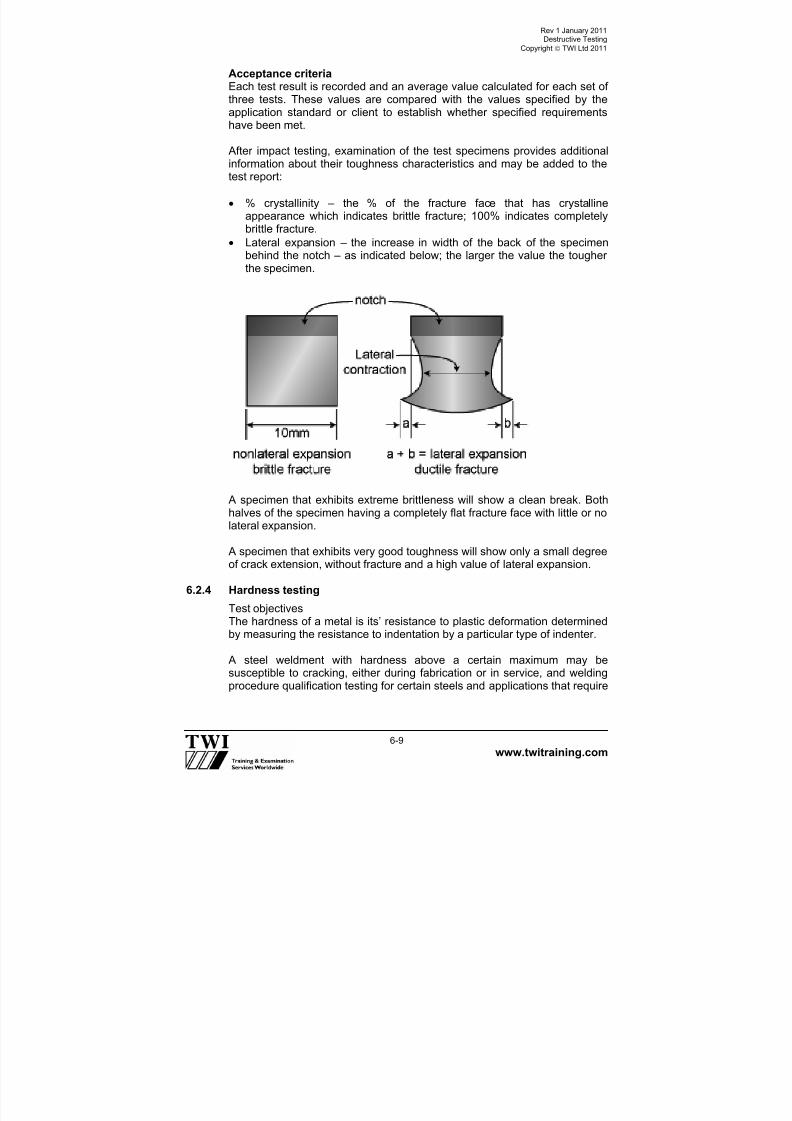
Acceptance criteriaEach test result is recorded and an average value calculated for each set ofthree tests. These values are compared with the values specified by theapplication standard or client to establish whether specified requirementshave been met.
After impact testing, examination of the test specimens provides additionalinformation about their toughness characteristics and may be added to thetest report:
% crystallinity – the % of the fracture face that has crystallineappearance which indicates brittle fracture; 100% indicates completelybrittle fracture.
Lateral expansion – the increase in width of the back of the specimenbehind the notch – as indicated below; the larger the value the tougherthe specimen.
A specimen that exhibits extreme brittleness will show a clean break. Bothhalves of the specimen having a completely flat fracture face with little or nolateral expansion.
A specimen that exhibits very good toughness will show only a small degreeof crack extension, without fracture and a high value of lateral expansion.
6.2.4 Hardness testing
Test objectivesThe hardness of a metal is its’ resistance to plastic deformation determinedby measuring the resistance to indentation by a particular type of indenter.
A steel weldment with hardness above a certain maximum may besusceptible to cracking, either during fabrication or in service, and weldingprocedure qualification testing for certain steels and applications that require

7/22/2019 CSWIP 3.2 LATEST WIS10-Mar-2011
http://slidepdf.com/reader/full/cswip-32-latest-wis10-mar-2011 60/303
Rev 1 January 2011Destructive Testing
Copyright TWI Ltd 2011
www.twitraining.com 6-10
the test weld to be hardness surveyed to ensure that are no regions of theweldment that exceed the maximum specified hardness.
Specimens prepared for macroscopic examination can also be used fortaking hardness measurements at various positions of the weldment –
referred to as a hardness survey.
Test methodsThere are 3 widely used methods for hardness testing:
Vickers hardness test uses a square-base diamond pyramid indenter.
Rockwell hardness test uses a diamond cone indenter or steel ball.
Brinell hardness test uses a ball indenter.
The hardness value being given by the size of the indentation producedunder a standard load, the smaller the indentation, the harder the metal.
The Vickers method of testing is illustrated below.
2
ddd 21
7/22/2019 CSWIP 3.2 LATEST WIS10-Mar-2011
http://slidepdf.com/reader/full/cswip-32-latest-wis10-mar-2011 61/303
Rev 1 January 2011Destructive Testing
Copyright TWI Ltd 2011
www.twitraining.com 6-11
Both Vickers and Brinell methods are suitable for carrying out hardnesssurveys on specimens prepared for macroscopic examination of weldments.
A typical hardness survey requires the indenter to measure the hardness inthe base metal (on both sides of the weld), in the weld metal and across the
HAZ (on both sides of the weld).
The Brinell method gives an indentation that is too large to accuratelymeasure the hardness in specific regions of the HAZ and is mainly used tomeasure hardness of base metals.
A typical hardness survey (using Vickers hardness indenter) is shownbelow:
Hardness values are shown on test reports as a number followed by lettersindicating the test method, for example:
240HV10 = hardness 240, Vickers method, 10kg indenter load.
22HRC = hardness 22, Rockwell method, diamond cone indenter(scale C).
238HBW = 238 hardness, Brinell method, tungsten ball indenter.
6.2.5 Crack tip opening displacement (CTOD) testing
Test objectiveCharpy V notch testing enables engineers to make judgements about risksof brittle fracture occurring in steels, but a CTOD test measures a material
property - fracture toughness.
Fracture toughness data enables engineers to carry out fracture mechanicsanalyses such as:
Calculating the size of a crack that would initiate a brittle fracture undercertain stress conditions at a particular temperature.
The stress that would cause a certain sized crack to give a brittle fractureat a particular temperature.
This data is essential for making an appropriate decision when a crack isdiscovered during inspection of equipment that is in-service.

7/22/2019 CSWIP 3.2 LATEST WIS10-Mar-2011
http://slidepdf.com/reader/full/cswip-32-latest-wis10-mar-2011 62/303
Rev 1 January 2011Destructive Testing
Copyright TWI Ltd 2011
www.twitraining.com 6-12
Test specimens A CTOD specimen is prepared as a rectangular (or square) shaped bar cuttransverse to the axis of the butt weld. A V notch is machined at the centreof the bar, which will be coincident with the test position - weld metal orHAZ.
A shallow saw cut is then put into the bottom of the notch and the specimenis then put into a machine that induces a cyclic bending load until a shallowfatigue crack initiates from the saw cut.
The specimens are relatively large – typically having a cross section B x 2Band length ~10B (B = full thickness of the weld). The test piece details areshown below.
Test methodCTOD specimens are usually tested at a temperature below ambient andthe temperature of the specimen is controlled by immersion in a bath ofliquid that has been cooled to the required test temperature.
A load is applied to the specimen to cause bending and induce aconcentrated stress at the tip of the crack and a clip gauge, attached to thespecimen across the mouth of the machined notch, gives a reading of theincrease in width of the mouth of the crack as the load is graduallyincreased.
For each test condition (position of notch and test temperature) it is usualpractice to carry out three tests.

7/22/2019 CSWIP 3.2 LATEST WIS10-Mar-2011
http://slidepdf.com/reader/full/cswip-32-latest-wis10-mar-2011 63/303
Rev 1 January 2011Destructive Testing
Copyright TWI Ltd 2011
www.twitraining.com 6-13
Below illustrates the main features of the CTOD test.
Fracture toughness is expressed as the distance that the crack tip openswithout initiation of a brittle crack.
The clip gauge enables a chart to be generated showing the increase inwidth of the crack mouth against applied load from which a CTOD value iscalculated.
Acceptance criteria An application standard or client may specify a minimum CTOD value thatindicates ductile tearing. Alternatively, the test may be for information so thata value can be used for an engineering critical assessment.
A very tough steel weldment will allow the mouth of the crack to open widelyby ductile tearing at the tip of the crack whereas a very brittle weldment willtend to fracture when the applied load is quite low and without any extensionat the tip of the crack.
7/22/2019 CSWIP 3.2 LATEST WIS10-Mar-2011
http://slidepdf.com/reader/full/cswip-32-latest-wis10-mar-2011 64/303
Rev 1 January 2011Destructive Testing
Copyright TWI Ltd 2011
www.twitraining.com 6-14
CTOD values are expressed in millimetres - typical values might be<<~0.1mm = brittle behaviour; >~1mm = very tough behaviour.
6.2.6 Bend testing
Test objectiveBend tests are routinely taken from welding procedure qualification testpieces and sometimes have to be taken from welder qualification testpieces.
Subjecting specimens to bending is a simple method of verifying that thereare no significant flaws in the joint. Some degree of ductility is alsodemonstrated.
Ductility is not actually measured but is demonstrated to be satisfactory iftest specimens can withstand being bent without fracture or fissures above
a certain length.
Test specimensThere are 4 types of bend specimen:
Face bendSpecimen taken with axis transverse to butt welds up to ~12mm thicknessand bent so that the face of the weld is on the outside of the bend (face intension).
Root bend
Test specimen taken with axis transverse to butt welds up to ~12mmthickness and bent so that the root of the weld is on the outside of the bend(root in tension).
Side bendTest specimen taken as a transverse slice (~10mm) from the full thicknessof butt welds >~12mm and bent so that the full joint thickness is tested (sidein tension).
Longitudinal bendTest specimen taken with axis parallel to the longitudinal axis of a butt weld;
specimen thickness is ~12mm and the face or root of weld may be tested intension.

7/22/2019 CSWIP 3.2 LATEST WIS10-Mar-2011
http://slidepdf.com/reader/full/cswip-32-latest-wis10-mar-2011 65/303
Rev 1 January 2011Destructive Testing
Copyright TWI Ltd 2011
www.twitraining.com 6-15
Test methodBend tests for welding procedure qualification (and welder qualification) areusually guided bend tests.
Guided means that the strain imposed on the specimen is uniformlycontrolled by being bent around a former with a certain diameter.
The diameter of the former used for a particular test is specified in the code,having been determined by the type of material that is being tested and theductility that can be expected from it after welding and any PWHT.
The diameter of the former is usually expressed as a multiple of thespecimen thickness and for C-Mn steel it is typically 4t (t is the specimenthickness) but for materials that have lower tensile ductility the radius of theformer may be greater than 10t.
The standard that specifies the test method will specify the minimum bendangle that the specimen must experience and this is typically 120-180°.
Acceptance criteriaBend test pieces should exhibit satisfactory soundness by not showingcracks or any signs of significant fissures or cavities on the outside of the
bend.

7/22/2019 CSWIP 3.2 LATEST WIS10-Mar-2011
http://slidepdf.com/reader/full/cswip-32-latest-wis10-mar-2011 66/303
Rev 1 January 2011Destructive Testing
Copyright TWI Ltd 2011
www.twitraining.com 6-16
Small indications less than about 3mm in length may be allowed by somestandards.
6.3 Fracture tests
6.3.1 Fillet weld fracturesTest objectiveThe quality/soundness of a fillet weld can be assessed by fracturing testpieces and examining the fracture surfaces.
This method for assessing the quality of fillet welds may be specified byapplication standards as an alternative to macroscopic examination.
It is a test method that can be used for welder qualification testing accordingto European Standards but is not used for welding procedure qualification toEuropean Standards.
Test specimens
A test weld is cut into short lengths (typically 50mm) and a longitudinalnotch is machined into the specimen as shown below. The notch profile maybe square, V or U shaped.
Test methodSpecimens are made to fracture through their throat by dynamic strokes(hammering) or by pressing, as shown below. The welding standard orapplication standard will specify the number of tests (typically 4).
Moving pressHammer stroke

7/22/2019 CSWIP 3.2 LATEST WIS10-Mar-2011
http://slidepdf.com/reader/full/cswip-32-latest-wis10-mar-2011 67/303
Rev 1 January 2011Destructive Testing
Copyright TWI Ltd 2011
www.twitraining.com 6-17
Acceptance criteriaThe standard for welder qualification, or application standard, will specify theacceptance criteria for imperfections such as lack of penetration into the rootof the joint and solid inclusions and porosity that are visible on the fracturesurfaces.
Test reports should also give a description of the appearance of the fractureand location of any imperfection
Butt weld fractures (nick-break tests)
Test objectiveThe objective of these fracture tests is the same as for fillet fracture tests.
These tests are specified for welder qualification testing to EuropeanStandards as an alternative to radiography. They are not used for weldingprocedure qualification testing to EU Standards.
Test specimensTest specimens are taken from a butt weld and notched so that the fracturepath will be in the central region of the weld. Typical test piece types areshown below.
Test methodTest pieces are made to fracture by hammering or three-point bending.
Acceptance criteriaThe standard for welder qualification, or application standard, will specify theacceptance criteria for imperfections such as lack of fusion, solid inclusions
and porosity that are visible on the fracture surfaces.

7/22/2019 CSWIP 3.2 LATEST WIS10-Mar-2011
http://slidepdf.com/reader/full/cswip-32-latest-wis10-mar-2011 68/303
Rev 1 January 2011Destructive Testing
Copyright TWI Ltd 2011
www.twitraining.com 6-18
Test reports should also give a description of the appearance of the fractureand location of any imperfection.
6.4 Macroscopic examination
Transverse sections from butt and fillet welds are required by the EUStandards for welding procedure qualification testing and may be requiredfor some welder qualification testing for assessing the quality of the welds.
This is considered in detail in a separate section of these course notes.
Macro examination Micro examination
Objectives
Detecting weld defects. (macro). Measuring grain size. (micro).
Detecting brittle structures, precipitates.
Assessing resistance toward brittle fracture, cold cracking and corrosionsensitivity.

7/22/2019 CSWIP 3.2 LATEST WIS10-Mar-2011
http://slidepdf.com/reader/full/cswip-32-latest-wis10-mar-2011 69/303
Rev 1 January 2011Destructive Testing
Copyright TWI Ltd 2011
www.twitraining.com 6-19
European Standards for Destructive Test Methods
The following Standards are specified by the European Welding Standardsfor destructive testing of welding procedure qualification test welds and forsome welder qualification test welds.
EN 875Destructive tests on welds in metallic materials – Impact tests – Testspecimen location, notch orientation and examination.
EN 895Destructive tests on welds in metallic materials – Transverse tensile test.
EN 910Destructive tests on welds in metallic materials – Bend tests.
EN 1321Destructive tests on welds in metallic materials – Macroscopic andmicroscopic examination of weld.
BS EN 10002Metallic materials - Tensile testing. Part 1: Method of test at ambienttemperature.
BS EN 10002Tensile testing of metallic materials. Part 5: Method of test at elevatedtemperatures.

7/22/2019 CSWIP 3.2 LATEST WIS10-Mar-2011
http://slidepdf.com/reader/full/cswip-32-latest-wis10-mar-2011 70/303
Section 7
Heat Treatment

7/22/2019 CSWIP 3.2 LATEST WIS10-Mar-2011
http://slidepdf.com/reader/full/cswip-32-latest-wis10-mar-2011 71/303
Rev 1 January 2011Heat Treatment
Copyright TWI Ltd 2011
www.twitraining.com 7-1
7 Heat Treatment
7.1 Introduction
The heat treatment given to a particular grade of steel by the steelmaker/supplier should be shown on the material test certificate and may bereferred to as the supply condition.
Welding inspectors may need to refer to material test certificates and it isappropriate that they be familiar with the terminology that is used and havesome understanding of the principles of some of the most commonly appliedheat treatments.
Welded joints may need to be subjected to heat treatment after welding(PWHT) and the tasks of monitoring the thermal cycle and checking the heattreatment records are often delegated to welding inspectors.
7.2 Heat treatment of steel
The main supply conditions for weldable steels are:
As rolled, hot rolled, hot finishedPlate is hot rolled to finished size and allowed to air cool; the temperature atwhich rolling finishes may vary from plate to plate and so strength andtoughness properties vary and are not optimised:
Applied to: Relatively thin, lower strength C-steel.
Thermo-mechanical controlled processing (TMCP), control rolled,thermo-mechanically rolled Steel plate given precisely controlled thickness reductions during hot rollingwithin carefully controlled temperature ranges; final rolling temperature isalso carefully controlled;
Applied toRelatively thin, high strength low alloy steels (HSLA) and for some steelswith good toughness at low temperatures, eg cryogenic steels.
Normalised After working the steel (rolling or forging) to size, it is heated to ~900°C andthen allowed to cool in air to ambient temperature; this optimises strengthand toughness and gives uniform properties from item to item for aparticular grade of steel;
Applied to C-Mn steels and some low alloy steels.

7/22/2019 CSWIP 3.2 LATEST WIS10-Mar-2011
http://slidepdf.com/reader/full/cswip-32-latest-wis10-mar-2011 72/303
Rev 1 January 2011Heat Treatment
Copyright TWI Ltd 2011
www.twitraining.com 7-2
Quenched and temperedafter working the steel (rolling or forging) to size, it is heated to ~900°C andthen cooled as quickly as possible by quenching in water or oil; afterquenching, the steel must be tempered (softened) to improve the ductility ofthe as-quenched steel:
Applied toSome low alloy steels to give higher strength, toughness or wear resistance.
Solution annealed/heat treated After hot or cold working to size, steel heated to ~1100°C and rapidly cooledby quenching into water to prevent any carbides or other phases fromforming:
Applied to Austenitic stainless steels such as 304 and 316 grades.
Annealed After working the steel (pressing or forging etc) to size, it is heated to~900°C and then allowed to cool in the furnace to ambient temperature; thisreduces strength and toughness but improves ductility:
Applied toC-Mn steels and some low alloy steels.
Figure 7.0-7.6 show the thermal cycles for the main supply conditions andsubsequent heat treatment that can be applied to steels.
7.3 Post weld heat treatment (PWHT)
Post weld heat treatment has to be applied to some welded steels to ensurethat the properties of the weldment will be suitable for their intendedapplications.
The temperature at which PWHT is carried out is usually well below thetemperature where phase changes can occur ( note 1 ), but high enough toallow residual stresses to be relieved quickly and to soften (temper) anyhard regions in the HAZ.
There are major benefits of reducing residual stress and ensuring that theHAZ hardness is not too high for particular steels with certain serviceapplications.
Examples of these benefits are:
Improved the resistance of the joint to brittle fracture.
Improved the resistance of the joint to stress corrosion cracking.
Enables welded joints to be machined to accurate dimensionaltolerances.

7/22/2019 CSWIP 3.2 LATEST WIS10-Mar-2011
http://slidepdf.com/reader/full/cswip-32-latest-wis10-mar-2011 73/303
Rev 1 January 2011Heat Treatment
Copyright TWI Ltd 2011
www.twitraining.com 7-3
Because the main reason for (and benefit of) PWHT is to reduce residualstresses, PWHT is often called stress relief .
Note 1: There are circumstances when a welded joint may need to benormalised to restore HAZ toughness. However, these are relatively rare
circumstances and it is necessary to ensure that welding consumables arecarefully selected because normalising will significantly reduce weld metalstrength.
7.4 PWHT thermal cycle
The application standard/code will specify when PWHT is required to givebenefits #1 or #2 above and also give guidance about the thermal cycle thatmust be used.
In order to ensure that a PWHT cycle is carried it in accordance with a
particular code, it is essential that a PWHT procedure is prepared and thatthe following parameters are specified:
Maximum heating rate.
Soak temperature range.
Minimum time at the soak temperature (soak time).
Maximum cooling rate.
7.4.1 Heating rate
This must be controlled to avoid large temperature differences within the
fabricated item. Large differences in temperature (large thermal gradients)will produce large stresses and these may be high enough to causedistortion (or even cracking).
Application standards usually require control of the maximum heating ratewhen the temperature of the item is above ~300°C. This is because steelsstart to show significant loss of strength above this temperature and aremore susceptible to distortion if there are large thermal gradients.
The temperature of the fabricated item must be monitored during thethermal cycle and this is done by means of thermocouples attached to the
surface at a number of locations representing the thickness range of theitem.
By monitoring furnace and item temperatures the rate of heating can becontrolled to ensure compliance with code requirements at all positionswithin the item.
Maximum heating rates specified for C-Mn steel depend on thickness of theitem but tend to be in the range ~60 to ~200°C/h.
7/22/2019 CSWIP 3.2 LATEST WIS10-Mar-2011
http://slidepdf.com/reader/full/cswip-32-latest-wis10-mar-2011 74/303
Rev 1 January 2011Heat Treatment
Copyright TWI Ltd 2011
www.twitraining.com 7-4
7.4.2 Soak temperature
The soak temperature specified by the code depends on the type of steeland thus the temperature range required to reduce residual stresses to alow level.
C and C-Mn steels require a soak temperature of ~600°C whereas somelow alloy steels (such as Cr-Mo steels used for elevated temperatureservice) require higher temperatures – typically in the range ~700 to~760°C.
Note: Soak temperature is an essential variable for a WPQR. Thus, it isvery important that the it is controlled within the specified limits otherwise itmay be necessary to carry out a new WPQ test to validate the properties ofthe item and at worst it may not be fit-for-purpose.
7.4.3 Soak timeIt is necessary to allow time for all the welded joints to experience thespecified temperature throughout the full joint thickness.
The temperature is monitored by surface-contact thermocouples and it is thethickest joint of the fabrication that governs the minimum time fortemperature equalisation.
Typical specified soak times are 1h per 25mm thickness.
7.4.4 Cooling rate
It is necessary to control the rate of cooling from the PWHT temperature forthe same reason that heating rate needs to be controlled – to avoiddistortion (or cracking) due to high stresses from thermal gradients.
Codes usually specify controlled cooling to ~300°C. Below this temperaturethe item can be withdrawn from a furnace and allowed to cool in air becausesteel is relatively strong and is unlikely to suffer plastic strain by anytemperature gradients that may develop.
Figure 6 is a typical PWHT thermal cycle.
7.5 Heat treatment furnaces
It is important that oil and gas-fired furnaces used for PWHT do not allowflame contact with the fabrication as this may induce large thermalgradients.
It is also important to ensure that the fuel (particularly for oil-fired furnaces)does not contain high levels of potentially harmful impurities – such assulphur.
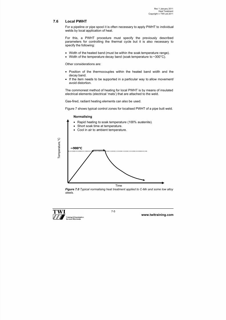
7/22/2019 CSWIP 3.2 LATEST WIS10-Mar-2011
http://slidepdf.com/reader/full/cswip-32-latest-wis10-mar-2011 75/303
Rev 1 January 2011Heat Treatment
Copyright TWI Ltd 2011
www.twitraining.com 7-5
7.6 Local PWHT
For a pipeline or pipe spool it is often necessary to apply PWHT to individualwelds by local application of heat.
For this, a PWHT procedure must specify the previously describedparameters for controlling the thermal cycle but it is also necessary tospecify the following:
Width of the heated band (must be within the soak temperature range).
Width of the temperature decay band (soak temperature to ~300°C).
Other considerations are:
Position of the thermocouples within the heated band width and thedecay band.
If the item needs to be supported in a particular way to allow movement/avoid distortion.
The commonest method of heating for local PWHT is by means of insulatedelectrical elements (electrical ‘mats’) that are attached to the weld.
Gas-fired, radiant heating elements can also be used.
Figure 7 shows typical control zones for localised PWHT of a pipe butt weld.
Figure 7.0 Typical normalising heat treatment applied to C-Mn and some low alloysteels.
T
e m p e r a t u r e , °
C
Time
~900°C
Normalising
Rapid heating to soak temperature (100% austenite).
Short soak time at temperature.
Cool in air to ambient temperature.

7/22/2019 CSWIP 3.2 LATEST WIS10-Mar-2011
http://slidepdf.com/reader/full/cswip-32-latest-wis10-mar-2011 76/303
Rev 1 January 2011Heat Treatment
Copyright TWI Ltd 2011
www.twitraining.com 7-6
Figure 7.1 Typical quenching and tempering heat treatment applied to some lowalloy steels.
Figure 7.2 Comparison of the ‘control-rolled’ (TMCP) and ‘as-rolled’ conditions (=
hot rolling).
T e m p e r a t u r e ° C
Time
~ 900°C
Quenching and tempering
Rapid heating to soak temperature (100% austenite).
Short soak time at temperature.
Rapid cooling by quenching in water or oil.
Reheat to tempering temperature, soak and air cool.
Quenching cycle
>~ 650°C
Tempering cycle
T e m p e r
a t u r e , °
C
Time
~900°C
Austenite + ferrite
(
Ferrite + pearlite
( + iron carbide)
As-rolledor
hot rolled
Slab heating temperature > ~1050°C
Austenite
(
~700°C
Control-rolledor
TMCP
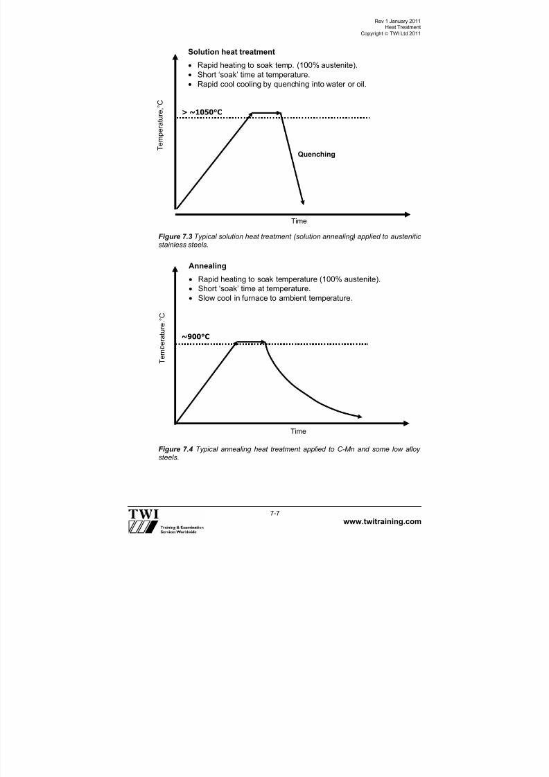
7/22/2019 CSWIP 3.2 LATEST WIS10-Mar-2011
http://slidepdf.com/reader/full/cswip-32-latest-wis10-mar-2011 77/303
Rev 1 January 2011Heat Treatment
Copyright TWI Ltd 2011
www.twitraining.com 7-7
Figure 7.3 Typical solution heat treatment (solution annealing) applied to austeniticstainless steels.
Figure 7.4 Typical annealing heat treatment applied to C-Mn and some low alloysteels.
T e m p e r a t u r e , °
C
Solution heat treatment
Rapid heating to soak temp. (100% austenite).
Short ‘soak’ time at temperature.
Rapid cool cooling by quenching into water or oil.
Time
> ~1050°C
Quenching
Annealing
Rapid heating to soak temperature (100% austenite).
Short ‘soak’ time at temperature. Slow cool in furnace to ambient temperature.
T e m
e r a t u r e ° C
Time
~900°C

7/22/2019 CSWIP 3.2 LATEST WIS10-Mar-2011
http://slidepdf.com/reader/full/cswip-32-latest-wis10-mar-2011 78/303

7/22/2019 CSWIP 3.2 LATEST WIS10-Mar-2011
http://slidepdf.com/reader/full/cswip-32-latest-wis10-mar-2011 79/303
Section 8
WPS and Welder Qualifications

7/22/2019 CSWIP 3.2 LATEST WIS10-Mar-2011
http://slidepdf.com/reader/full/cswip-32-latest-wis10-mar-2011 80/303
Rev 1 January 2011WPS and Welder Qualifications
Copyright TWI Ltd 2011
www.twitraining.com 8-1
8 WPS and Welder Qualifications
8.1 General
When structures and pressurised items are fabricated by welding, it isessential that all the welded joints are sound and have suitable propertiesfor their application.
Control of welding is by means of welding procedure specifications (WPS)that give detailed written instructions about the welding conditions that mustbe used to ensure that welded joints have the required properties.
Although WPS are shop floor documents to instruct welders, weldinginspectors need to be familiar with them because they will need to refer toWPSs when they are checking that welders are working in accordance withthe specified requirements.
Welders need to understand WPSs and have the skill to make welds thatare not defective and demonstrate these abilities before being allowed tomake production welds.
8.2 Qualified welding procedure specifications
It is industry practice to use qualified WPS for most applications.
A welding procedure is usually qualified by making a test weld todemonstrate that the properties of the joint satisfy the requirementsspecified by the application standard (and the client/end user).
Demonstrating the mechanical properties of the joint is the principal purposeof qualification tests but showing that a defect-free weld can be produced isalso very important.
Production welds that are made in accordance with welding conditionssimilar to those used for a test weld should have similar properties andtherefore be fit for their intended purpose.
Figure 1 is an example of a typical WPS written in accordance with the
European Welding Standard format giving details of all the weldingconditions that need to be specified.
8.2.1 Welding standards for procedure qualification
European and American Standards have been developed to givecomprehensive details about:
How a welded test piece must be made to demonstrate joint properties.
How the test piece must be tested.
What welding details need to be included in a WPS?

7/22/2019 CSWIP 3.2 LATEST WIS10-Mar-2011
http://slidepdf.com/reader/full/cswip-32-latest-wis10-mar-2011 81/303
Rev 1 January 2011WPS and Welder Qualifications
Copyright TWI Ltd 2011
www.twitraining.com 8-2
The range of production welding allowed by a particular qualification testweld.
The principal European Standards that specify these requirements are:
EN ISO 15614 Specification and qualification of welding procedures formetallic materials – Welding procedure test.
Part 1: Arc & gas welding of steels & arc welding of nickel & nickel alloys.
Part 2: Arc welding of aluminium and its alloys.
The principal American Standards for procedure qualification are:
ASME Section IX for pressurised systems (vessels & pipework).
AWS D1.1 Structural welding of steels.
AWS D1.2 Structural welding of aluminium.
8.2.2 The qualification process for welding procedures
Although qualified WPS are usually based on test welds that have beenmade to demonstrate weld joint properties; welding standards also allowqualified WPS to be written based on other data (for some applications).
Some alternative ways that can be used for writing qualified WPS for some
applications are:
Qualification by adoption of a standard welding procedure - testwelds previously qualified and documented by other manufacturers.
Qualification based on previous welding experience - weld joints thathave been repeatedly made and proved to have suitable properties bytheir service record.
Procedure qualification to European Standards by means of a test weld (andsimilar in ASME Section IX and AWS) requires a sequence of actions that is
typified by those shown by Table 1.
A successful procedure qualification test is completed by the production of awelding procedure qualification record (WPQR), an example of which isshown by Figure 2.
8.2.3 Relationship between a WPQR and a WPS
Once a WPQR has been produced, the welding engineer is able to writequalified WPSs for the various production weld joints that need to be made.

7/22/2019 CSWIP 3.2 LATEST WIS10-Mar-2011
http://slidepdf.com/reader/full/cswip-32-latest-wis10-mar-2011 82/303
Rev 1 January 2011WPS and Welder Qualifications
Copyright TWI Ltd 2011
www.twitraining.com 8-3
The welding conditions that are allowed to be written on a qualified WPS arereferred to as the qualification range and this range depends on thewelding conditions that were used for the test piece (the as-run details) andform part of the WPQR.
Welding conditions are referred to as welding variables by European and American Welding Standards and are classified as either essentialvariables or non-essential variables.
These variables can be defined as follows:
Essential variable a variable that has an effect on the mechanicalproperties of the weldment (and if changed beyond the limits specified bythe standard will require the WPS to be re-qualified).
Non-essential variable a variable that must be specified on a WPS butdoes not have a significant effect on the mechanical properties of the
weldment (and can be changed without need for re-qualification butwill require a new WPS to be written).
It is because essential variables can have a significant effect on mechanicalproperties that they are the controlling variables that govern the qualificationrange and determine what can be written into a WPS.
If a welder makes a production weld using conditions outside thequalification range given on a particular WPS, there is danger that thewelded joint will not have the required properties and there are then two
options:
Make another test weld using similar welding conditions to those usedfor the affected weld and subject this to the same tests used for therelevant WPQR to demonstrate that the properties still satisfy specifiedrequirements.
Remove the affected weld and re-weld the joint strictly in accordancewith the designated WPS.
Most of the welding variables that are classed as essential are the same inboth the European and American Welding Standards but their qualification
ranges may differ.
Some Application Standards specify their own essential variables and it isnecessary to ensure that these are taken into consideration whenprocedures are qualified and WPSs are written.
Examples of essential variables (according to European Welding Standards)are given in Table 2.

7/22/2019 CSWIP 3.2 LATEST WIS10-Mar-2011
http://slidepdf.com/reader/full/cswip-32-latest-wis10-mar-2011 83/303
Rev 1 January 2011WPS and Welder Qualifications
Copyright TWI Ltd 2011
www.twitraining.com 8-4
8.3 Welder qualification
The use of qualified WPSs is the accepted method for controlling productionwelding but this will only be successful if the welders have the ability tounderstand and work in accordance with them.
Welders also need to have the skill to consistently produce sound welds(free from defects).
Welding Standards have been developed to give guidance on whatparticular test welds are required in order to show that welders have therequired skills to make particular types of production welds in particularmaterials.
8.3.1 Welding standards for welder qualification
The principal European Standards that specify requirements are:
EN 287-1 Qualification test of welders – Fusion weldingPart 1: Steels
EN ISO 9606-2 Qualification test of welders – Fusion weldingPart 2: Aluminium and aluminium alloys
EN 1418 Welding personnel – Approval testing of weldingoperators for fusion welding and resistance weld settersfor fully mechanised and automatic welding of metallicmaterials
The principal American Standards that specify requirements for welderqualification are:
ASME Section IX Pressurised systems (vessels & pipework)
AWS D1.1 Structural welding of steels
AWS D1.2 Structural welding of aluminium
8.3.2 The qualification process for weldersQualification testing of welders to European Standards requires test weldsto be made and subjected to specified tests to demonstrate that the welderunderstands the WPS and can produce a sound weld.
For manual and semi-automatic welding the emphasis of the tests is todemonstrate ability to manipulate the electrode or welding torch.
For mechanised and automatic welding the emphasis is on demonstratingthat welding operators have ability to control particular types of weldingequipment.
7/22/2019 CSWIP 3.2 LATEST WIS10-Mar-2011
http://slidepdf.com/reader/full/cswip-32-latest-wis10-mar-2011 84/303
Rev 1 January 2011WPS and Welder Qualifications
Copyright TWI Ltd 2011
www.twitraining.com 8-5
American Standards allow welders to demonstrate that they can producesound welds by subjecting their first production weld to non-destructivetesting.
Table 3 shows the steps required for qualifying welders in accordance with
European Standards.
Figure 3 shows a typical Welder Qualification Certificate in accordance withEuropean Standards.
8.3.3 Welder qualification and production welding allowed
The welder is allowed to make production welds within the range ofqualification recorded on his welder qualification certificate.
The range of qualification is based on the limits specified by the Welding
Standard for welder qualification essential variabless - defined as: avariable that if changed beyond the limits specified by the WeldingStandard may require greater skill than has been demonstrated by thetest weld.
Some welding variables that are classed as essential for welder qualificationare the same types as those classified as essential for welding procedurequalification, but the range of qualification may be significantly wider.
Some essential variables are specific to welder qualification.
Examples of welder qualification essential variables are given in Table 4.
8.3.4 Period of validity for a welder qualification certificate
A welder’s qualification begins from the date of welding of the test piece.
The European Standard allows a qualification certificate to remain valid for aperiod of two years – provided that:
The welding co-ordinator, or other responsible person, can confirm thatthe welder has been working within the initial range of qualification.
Working within the initial qualification range is confirmed every sixmonths.
7/22/2019 CSWIP 3.2 LATEST WIS10-Mar-2011
http://slidepdf.com/reader/full/cswip-32-latest-wis10-mar-2011 85/303
Rev 1 January 2011WPS and Welder Qualifications
Copyright TWI Ltd 2011
www.twitraining.com 8-6
8.3.5 Prolongation of welder qualification
A welder’s qualification certificate can be prolonged every two years by anexaminer/examining body but before prolongation is allowed certainconditions need to be satisfied:
Records/evidence are available that can be traced to the welder and theWPS that have been used for production welding.
The supporting evidence must relate to volumetric examination of thewelder’s production welds (RT or UT) on two welds made during the 6months prior to the prolongation date.
The supporting evidence welds must satisfy the acceptance levels forimperfections specified by the European welding standard and havebeen made under the same conditions as the original test weld.
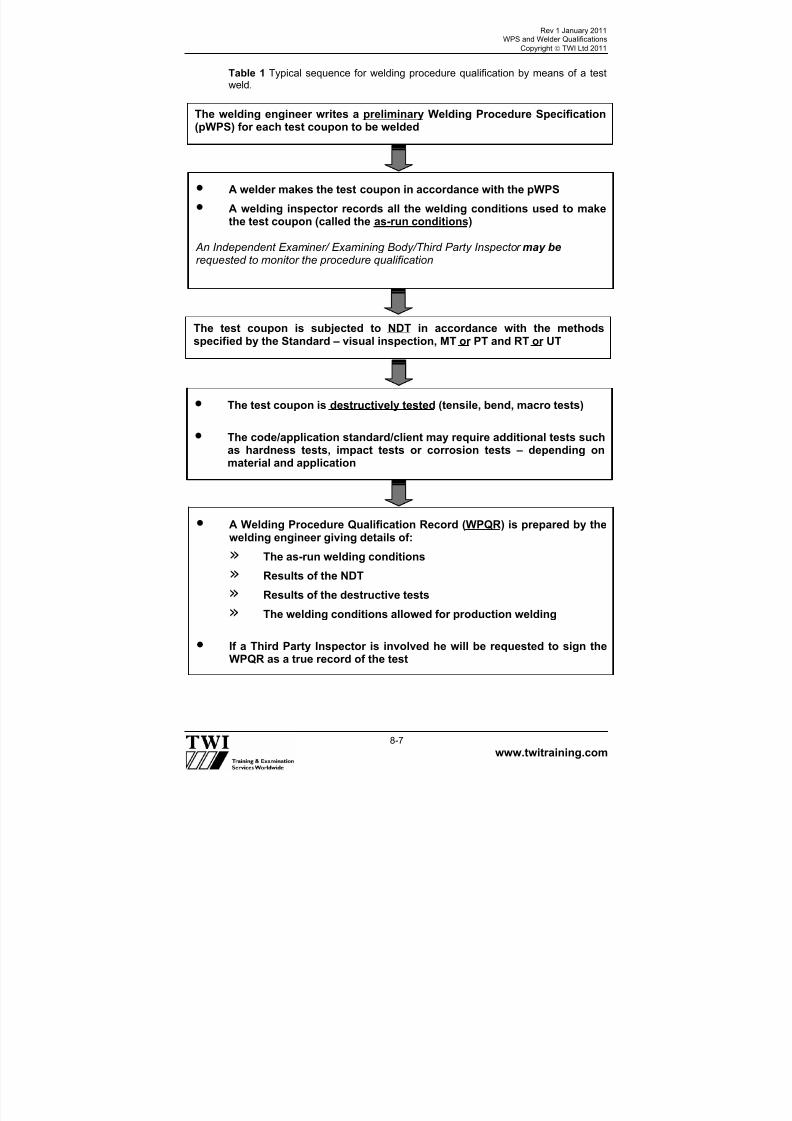
7/22/2019 CSWIP 3.2 LATEST WIS10-Mar-2011
http://slidepdf.com/reader/full/cswip-32-latest-wis10-mar-2011 86/303
Rev 1 January 2011WPS and Welder Qualifications
Copyright TWI Ltd 2011
www.twitraining.com 8-7
Table 1 Typical sequence for welding procedure qualification by means of a testweld.
The welding engineer writes a preliminary Welding Procedure Specification(pWPS) for each test coupon to be welded
• A welder makes the test coupon in accordance with the pWPS
• A welding inspector records all the welding conditions used to makethe test coupon (called the as-run conditions)
An Independent Examiner/ Examining Body/Third Party Inspector may be requested to monitor the procedure qualification
The test coupon is subjected to NDT in accordance with the methodsspecified by the Standard – visual inspection, MT or PT and RT or UT
• A Welding Procedure Qualification Record (WPQR) is prepared by thewelding engineer giving details of:
» The as-run welding conditions
» Results of the NDT
» Results of the destructive tests
» The welding conditions allowed for production welding
• If a Third Party Inspector is involved he will be requested to sign theWPQR as a true record of the test
• The test coupon is destructively tested (tensile, bend, macro tests)
• The code/application standard/client may require additional tests suchas hardness tests, impact tests or corrosion tests – depending onmaterial and application

7/22/2019 CSWIP 3.2 LATEST WIS10-Mar-2011
http://slidepdf.com/reader/full/cswip-32-latest-wis10-mar-2011 87/303
Rev 1 January 2011WPS and Welder Qualifications
Copyright TWI Ltd 2011
www.twitraining.com 8-8
Table 2 Typical examples of WPS essential variables according to European WeldingStandards.
VARIABLE RANGE for PROCEDURE QUALIFICATION
Welding process No range – process qualified is process that must be
used in production
PWHT Joints tested after PWHT only qualify as PWHTproduction jointsJoints tested ‘as-welded’ only qualify ‘as-welded’production joints
Parent materialtype
Parent materials of similar composition and mechanicalproperties are allocated the same Material Group No.;qualification only allows production welding of materialswith the same Group No.
Weldingconsumables
Consumables for production welding must have the sameEuropean designation – as a general rule
Materialthickness
A thickness range is allowed – below and above the testcoupon thickness
Type of current AC only qualifies for AC; DC polarity (+VE or -VE) cannotbe changed; pulsed current only qualifies for pulsedcurrent production welding
Preheattemperature
The preheat temperature used for the test is the minimumthat must be applied
Interpasstemperature
The highest interpass temperature reached in the test isthe maximum allowed
Heat input (HI) When impact requirements apply maximum HI allowed is25% above test HIwhen hardness requirements apply minimum HI allowedis 25% below test HI

7/22/2019 CSWIP 3.2 LATEST WIS10-Mar-2011
http://slidepdf.com/reader/full/cswip-32-latest-wis10-mar-2011 88/303
Rev 1 January 2011WPS and Welder Qualifications
Copyright TWI Ltd 2011
www.twitraining.com 8-9
Table 3 Stages for qualification of a welder.
The welding engineer writes a WPS for welder qualification test piece
• The welder makes the test weld in accordance with the WPS
A welding inspector monitors the welding to ensure that the welder isworking in accordance the WPS
An Independent Examiner/Examining Body/Third Party Inspector may be requested to monitor the test
• The test coupon is subjected to NDT in accordance with the methodsspecified by the Standard (visual inspection, MT or PT and RT or UT)
• For certain materials, and welding processes, some destructivetesting may be required (bends or macros)
• A Welder’s Qualification Certificate is prepared showing the weldingconditions used for the test piece and the range of qualificationallowed by the Standard for production welding
• If a Third Party is involved, the Qualification Certificate would beendorsed as a true record of the test
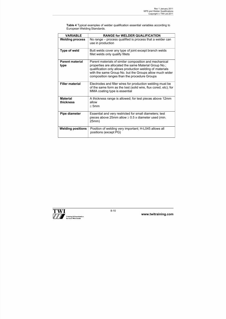
7/22/2019 CSWIP 3.2 LATEST WIS10-Mar-2011
http://slidepdf.com/reader/full/cswip-32-latest-wis10-mar-2011 89/303
Rev 1 January 2011WPS and Welder Qualifications
Copyright TWI Ltd 2011
www.twitraining.com 8-10
Table 4 Typical examples of welder qualification essential variables according toEuropean Welding Standards.
VARIABLE RANGE for WELDER QUALIFICATION
Welding process No range – process qualified is process that a welder canuse in production
Type of weld Butt welds cover any type of joint except branch weldsfillet welds only qualify fillets
Parent materialtype
Parent materials of similar composition and mechanicalproperties are allocated the same Material Group No.;qualification only allows production welding of materialswith the same Group No. but the Groups allow much widercomposition ranges than the procedure Groups
Filler material Electrodes and filler wires for production welding must beof the same form as the test (solid wire, flux cored, etc); forMMA coating type is essential
Materialthickness
A thickness range is allowed; for test pieces above 12mmallow
5mm
Pipe diameter Essential and very restricted for small diameters; test
pieces above 25mm allow 0.5 x diameter used (min.25mm)
Welding positions Position of welding very important; H-L045 allows allpositions (except PG)

7/22/2019 CSWIP 3.2 LATEST WIS10-Mar-2011
http://slidepdf.com/reader/full/cswip-32-latest-wis10-mar-2011 90/303
Rev 1 January 2011WPS and Welder Qualifications
Copyright TWI Ltd 2011
www.twitraining.com 8-11

7/22/2019 CSWIP 3.2 LATEST WIS10-Mar-2011
http://slidepdf.com/reader/full/cswip-32-latest-wis10-mar-2011 91/303
Rev 1 January 2011WPS and Welder Qualifications
Copyright TWI Ltd 2011
www.twitraining.com 8-12

7/22/2019 CSWIP 3.2 LATEST WIS10-Mar-2011
http://slidepdf.com/reader/full/cswip-32-latest-wis10-mar-2011 92/303
Rev 1 January 2011WPS and Welder Qualifications
Copyright TWI Ltd 2011
www.twitraining.com 8-13

7/22/2019 CSWIP 3.2 LATEST WIS10-Mar-2011
http://slidepdf.com/reader/full/cswip-32-latest-wis10-mar-2011 93/303
Rev 1 January 2011WPS and Welder Qualifications
Copyright TWI Ltd 2011
www.twitraining.com 8-14

7/22/2019 CSWIP 3.2 LATEST WIS10-Mar-2011
http://slidepdf.com/reader/full/cswip-32-latest-wis10-mar-2011 94/303
Rev 1 January 2011WPS and Welder Qualifications
Copyright TWI Ltd 2011
www.twitraining.com 8-15

7/22/2019 CSWIP 3.2 LATEST WIS10-Mar-2011
http://slidepdf.com/reader/full/cswip-32-latest-wis10-mar-2011 95/303
Section 9
Materials Inspection

7/22/2019 CSWIP 3.2 LATEST WIS10-Mar-2011
http://slidepdf.com/reader/full/cswip-32-latest-wis10-mar-2011 96/303
Rev 1 January 2011Materials Inspection
Copyright TWI Ltd 2011
www.twitraining.com 9-1
9 Materials Inspection
9.1 General
One of the duties of the Visual/Welding Inspector is to carry out materialsinspection. There are a number of situations where the inspector will berequired to carry out materials inspection:
At the plate or pipe mill.
Of material during fabrication or construction.
Of material after installation, usually during a planned maintenanceprogramme, outage or shutdown.
A wide range of materials are available, that can be used in fabrication andwelding. These include, but are not limited to:
Steels. Stainless steels.
Aluminium and its alloys.
Nickel and its alloys.
Copper and its alloys.
Titanium and its alloys.
Cast iron.
These materials are all widely used in fabrication, welding and constructionto meet the requirements of a diverse range of applications and industrysectors.
There are three essential aspects to materials inspection that the Inspectorshould consider:
Material type and weldability.
Material traceability.
Material condition and dimensions.
9.2 Material types and weldability
A Welding Inspector must be able to understand and interpret the materialdesignation in order to check compliance with relevant normativedocuments. For example materials standards such as BS EN, API, ASTM,the welding procedure specification (WPS), the purchase order, fabricationdrawings, the quality plan/the contract specification and client requirements.
A commonly used material standard for steel designation is BS EN 10025 –Hot rolled products of non-alloy structural steels.

7/22/2019 CSWIP 3.2 LATEST WIS10-Mar-2011
http://slidepdf.com/reader/full/cswip-32-latest-wis10-mar-2011 97/303

7/22/2019 CSWIP 3.2 LATEST WIS10-Mar-2011
http://slidepdf.com/reader/full/cswip-32-latest-wis10-mar-2011 98/303
Rev 1 January 2011Materials Inspection
Copyright TWI Ltd 2011
www.twitraining.com 9-3
To trace the history of the material, reference to the inspection documentsmust be made. BS EN 10204 Metallic products – Types of inspectiondocuments is the standard, which provides guidance on these types ofdocument. Under BS EN 10204 inspection documents fall into two types:
a) Non-specific inspectionInspection carried out by the manufacturer in accordance with his ownprocedures to assess whether products defined by the same productspecification and made by the same manufacturing process, are incompliance with the requirements of the order or not.
Type 2.1 are documents in which the manufacturer declares that theproducts supplied are in compliance with the requirements of the order without inclusion of test results.
Type 2.2 are documents in which the manufacturer declares that the
products supplied are in compliance with the requirements of the order andin which test results based on non-specific inspection are supplied.
b) Specific inspectionInspection carried out, before delivery, according to the productspecification, on the products to be supplied or on test units of which theproducts supplied are part, in order to verify that these products are incompliance with the requirements of the order.
Type 3.1 are documents in which the manufacturer declares that theproducts supplied are in compliance with the requirements of the order andin which test results are supplied.
Type 3.2 are documents prepared by both the manufacturer’s authorisedinspection representative independent of the manufacturing department,and either the purchaser’s authorised representative or the inspectordesignated by the official regulations, and in which they declare that theproducts supplied are in compliance with the requirements of the orderand in which test results are supplied.
Application or location of a particular material can be carried out through a
review of the welding procedure specification (WPS), the fabricationdrawings, the quality plan or by physical inspection of the material at thepoint of use.
In certain circumstances the Inspector may have to witness the transfer ofcast numbers from the original plate to pieces to be used in production.
On pipeline work it is a requirement that the inspector records all therelevant information for each piece of line pipe. On large diameter pipes thisinformation is usually stencilled on the inside of the pipe. On smallerdiameter pipes the information may be stencilled along the outside of the
pipe.

7/22/2019 CSWIP 3.2 LATEST WIS10-Mar-2011
http://slidepdf.com/reader/full/cswip-32-latest-wis10-mar-2011 99/303

7/22/2019 CSWIP 3.2 LATEST WIS10-Mar-2011
http://slidepdf.com/reader/full/cswip-32-latest-wis10-mar-2011 100/303
Rev 1 January 2011Materials Inspection
Copyright TWI Ltd 2011
www.twitraining.com 9-5
9.5 Material condition and dimensions
The condition of the material could have an adverse effect on the service lifeof the component; it is therefore an important inspection point. The points forinspection must include:
General inspection, visible imperfections, dimensions and surface condition.
General inspectionThis type of inspection takes account of storage conditions, methods ofhandling, the number of plates or pipes and distortion tolerances.
Visible imperfectionsTypical visible imperfections are usually attributable to the manufacturingprocess and would include cold laps, which break the surface or laminationsif they appear at the edge of the plate. For laminations, which may be
present in the body of the material, ultrasonic testing using a compressionprobe may be required.
Cold lap Plate lamination
Dimensions For plates this would include length, width and thickness.
For pipes, this would not only include length and wall thickness, but alsoinspection of diameter and ovality. At this stage of the inspection thematerial cast or heat number may also be recorded for validation against thematerial certificate.
Surface conditionThe surface condition of the material is important, it must not show
excessive mill scale and rust, must not be badly pitted, or haveunacceptable mechanical damage.

7/22/2019 CSWIP 3.2 LATEST WIS10-Mar-2011
http://slidepdf.com/reader/full/cswip-32-latest-wis10-mar-2011 101/303

7/22/2019 CSWIP 3.2 LATEST WIS10-Mar-2011
http://slidepdf.com/reader/full/cswip-32-latest-wis10-mar-2011 102/303
Rev 1 January 2011Materials Inspection
Copyright TWI Ltd 2011
www.twitraining.com 9-7
9.6 Summary
Material inspection is an important part of the Inspector’s duties and anunderstanding of the documentation involved is the key to success.
Material inspection must be approached in a logical and precise manner ifmaterial verification and traceability are to be achieved. This can be difficultif the material is not readily accessible, access may have to be provided,safety precautions observed and authorisation obtained before materialinspection can be carried out. Reference to the quality plan should identifythe level of inspection required and the point at which inspection takesplace. Reference to a fabrication drawing should provide information on thetype and location of the material.
If material type cannot be determined from the inspection documentsavailable, or if the inspection document is missing, other methods of
identifying the material may need to be used.
These methods may include but are not limited to: spark test, spectroscopicanalysis, chemical analysis, scleroscope hardness test, etc. These types oftests are normally conducted by an approved test house, but sometimes onsite, and the Inspector may be required to witness these tests in order toverify compliance with the purchase order or appropriate standard(s).
*EN ISO 9000 Quality management systems – Fundamentals and vocabulary

7/22/2019 CSWIP 3.2 LATEST WIS10-Mar-2011
http://slidepdf.com/reader/full/cswip-32-latest-wis10-mar-2011 103/303

7/22/2019 CSWIP 3.2 LATEST WIS10-Mar-2011
http://slidepdf.com/reader/full/cswip-32-latest-wis10-mar-2011 104/303
Rev 1 January 2011Residual Stress and Distortion
Copyright TWI Ltd 2011
www.twitraining.com 10-1
10 Residual Stress and Distortion
10.1 What causes distortion?
Because welding involves highly localised heating of joint edges to fuse thematerial, non-uniform stresses are set up in the component because ofexpansion and contraction of the heated material.
Initially, compressive stresses are created in the surrounding cold parentmetal when the weld pool is formed due to the thermal expansion of the hotmetal (heat affected zone (HAZ)) adjacent to the weld pool. However,tensile stresses occur on cooling when the contraction of the weld metal andimmediate HAZ is resisted by the bulk of the cold parent metal.
The magnitude of thermal stresses induced into the material can be seen bythe volume change in the weld area on solidification and subsequent cooling
to room temperature. For example, when welding C-Mn steel, the moltenweld metal volume will be reduced by approximately 3% on solidificationand the volume of the solidified weld metal/HAZ will be reduced by a further7% as its temperature falls from the melting point of steel to roomtemperature.
If the stresses generated from thermal expansion/contraction exceed theyield strength of the parent metal, localised plastic deformation of the metaloccurs. Plastic deformation causes a permanent reduction in the componentdimensions and distorts the structure.
10.2 What are the main types of distortion?Distortion occurs in several ways:
Longitudinal shrinkage.
Transverse shrinkage.
Angular distortion.
Bowing and dishing.
Buckling.
Contraction of the weld area on cooling results in both transverse and
longitudinal shrinkage.
Non-uniform contraction (through thickness) produces angular distortion aswell as longitudinal and transverse shrinking.
For example, in a single V butt weld, the first weld run produces longitudinaland transverse shrinkage and rotation. The second run causes the plates torotate using the first weld deposit as a fulcrum. Therefore balanced weldingin a double side V butt joint can be used to produce uniform contraction andprevent angular distortion.

7/22/2019 CSWIP 3.2 LATEST WIS10-Mar-2011
http://slidepdf.com/reader/full/cswip-32-latest-wis10-mar-2011 105/303
Rev 1 January 2011Residual Stress and Distortion
Copyright TWI Ltd 2011
www.twitraining.com 10-2
Similarly, in a single-sided fillet weld, non-uniform contraction will produceangular distortion of the upstanding leg. Double-sided fillet welds cantherefore be used to control distortion in the upstanding fillet but becausethe weld is only deposited on one side of the base plate, angular distortionwill now be produced in the plate.
Longitudinal bowing in welded plates happens when the weld centre is notcoincident with the neutral axis of the section so that longitudinal shrinkagein the welds bends the section into a curved shape. Clad plate tends to bowin two directions due to longitudinal and transverse shrinkage of thecladding. This produces a dished shape.
Dishing is also produced in stiffened plating. Plates usually dish inwardsbetween the stiffeners, because of angular distortion at the stiffenerattachment welds.
In plating, long range compressive stresses can cause elastic buckling inthin plates, resulting in dishing, bowing or rippling, see below.
Examples of distortion
Examples of distortion.
Increasing the leg length of fillet welds, in particular, increases shrinkage.
10.3 What are the factors affecting distortion?
If a metal is uniformly heated and cooled there would be almost nodistortion. However, because the material is locally heated and restrained bythe surrounding cold metal, stresses are generated higher than the materialyield stress causing permanent distortion. The principal factors affecting thetype and degree of distortion are:
Parent material properties.
Amount of restraint.
Joint design.
7/22/2019 CSWIP 3.2 LATEST WIS10-Mar-2011
http://slidepdf.com/reader/full/cswip-32-latest-wis10-mar-2011 106/303
Rev 1 January 2011Residual Stress and Distortion
Copyright TWI Ltd 2011
www.twitraining.com 10-3
Part fit-up.
Welding procedure.
10.3.1 Parent material properties
Parent material properties, which influence distortion, are coefficient ofthermal expansion, thermal conductivity, and to a lesser extent, yield stressand Young’s modulus. As distortion is determined by expansion andcontraction of the material, the coefficient of thermal expansion of thematerial plays a significant role in determining the stresses generated duringwelding and, hence, the degree of distortion. For example, as stainless steelhas a higher coefficient of expansion and lesser thermal conductivity thanplain carbon steel, it generally has significantly more distortion.
10.3.2 Restraint
If a component is welded without any external restraint, it distorts to relieve
the welding stresses. So, methods of restraint, such as strongbacks in buttwelds, can prevent movement and reduce distortion. As restraint produceshigher levels of residual stress in the material, there is a greater risk ofcracking in weld metal and HAZ especially in crack-sensitive materials.
10.3.3 Joint design
Both butt and fillet joints are prone to distortion, but it can be minimised inbutt joints by adopting a joint type, which balances the thermal stressesthrough the plate thickness. For example, double- in preference to a single-sided weld. Double-sided fillet welds should eliminate angular distortion of
the upstanding member, especially if the two welds are deposited at thesame time.
10.3.4 Part fit-up
Fit-up should be uniform to produce predictable and consistent shrinkage.Excessive joint gap can also increase the degree of distortion by increasingthe amount of weld metal needed to fill the joint. The joints should beadequately tacked to prevent relative movement between the parts duringwelding.
10.3.5 Welding procedure
This influences the degree of distortion mainly through its effect on the heatinput. As welding procedures are usually selected for reasons of quality andproductivity, the welder has limited scope for reducing distortion. As ageneral rule, weld volume should be kept to a minimum. Also, the weldingsequence and technique should aim to balance the thermally inducedstresses around the neutral axis of the component.

7/22/2019 CSWIP 3.2 LATEST WIS10-Mar-2011
http://slidepdf.com/reader/full/cswip-32-latest-wis10-mar-2011 107/303
Rev 1 January 2011Residual Stress and Distortion
Copyright TWI Ltd 2011
www.twitraining.com 10-4
10.4 Distortion - prevention by pre-setting, pre-bending or use ofrestraint
Distortion can often be prevented at the design stage, for example, byplacing the welds about the neutral axis, reducing the amount of welding
and depositing the weld metal using a balanced welding technique. Indesigns where this is not possible, distortion may be prevented by one ofthe following methods:
Pre-setting of parts.
Pre-bending of parts.
Use of restraint.
The technique chosen will be influenced by the size and complexity of thecomponent or assembly, the cost of any restraining equipment and the needto limit residual stresses.
Pre-setting of parts to produce correct alignment after welding.
a)Pre-setting of fillet joint to prevent angular distortion.b)Pre-setting of butt joint to prevent angular distortion.
10.4.1 Pre-setting of parts
The parts are pre-set and left free to move during welding (see above). Inpractice, the parts are pre-set by a pre-determined amount so that distortionoccurring during welding is used to achieve overall alignment anddimensional control.
The main advantages compared with the use of restraint are that there is no
expensive equipment needed and there will be lower residual stress in thestructure.
Unfortunately, as it is difficult to predict the amount of pre-setting needed toaccommodate shrinkage, a number of trial welds will be required. Forexample, when MMA or MIG/MAG welding butt joints, the joint gap willnormally close ahead of welding; when submerged arc welding; the jointmay open up during welding. When carrying out trial welds, it is alsoessential that the test structure is reasonably representative of the full sizestructure in order to generate the level of distortion likely to occur in practice.For these reasons, pre-setting is a technique more suitable for simple
components or assemblies.

7/22/2019 CSWIP 3.2 LATEST WIS10-Mar-2011
http://slidepdf.com/reader/full/cswip-32-latest-wis10-mar-2011 108/303
Rev 1 January 2011Residual Stress and Distortion
Copyright TWI Ltd 2011
www.twitraining.com 10-5
Pre-bending, using strongbacks and wedges, to accommodate angular distortion inthin plates.
10.4.2 Pre-bending of parts
Pre-bending, or pre-springing the parts before welding is used to pre-stressthe assembly to counteract shrinkage during welding. As shown above, pre-bending by means of strongbacks and wedges can be used to pre-set aseam before welding to compensate for angular distortion. Releasing thewedges after welding will allow the parts to move back into alignment.
The figure shows the diagonal bracings and centre jack used to pre-bendthe fixture, not the component. This counteracts the distortion introducedthough out-of-balance welding.
10.4.3 Use of restraint
Because of the difficulty in applying pre-setting and pre-bending, restraint isthe more widely practised technique. The basic principle is that the parts are
placed in position and held under restraint to minimise any movement duringwelding. When removing the component from the restraining equipment, arelatively small amount of movement will occur due to locked-in stresses.This can be cured by either applying a small amount of pre-set or stress-relieving before removing the restraint.
When welding assemblies, all the component parts should be held in thecorrect position until completion of welding and a suitably balancedfabrication sequence used to minimise distortion.
Welding with restraint will generate additional residual stresses in the weld,
which may cause cracking. When welding susceptible materials, a suitablewelding sequence and the use of preheating will reduce this risk.Restraint is relatively simple to apply using clamps, jigs and fixtures to holdthe parts during welding.
Welding jigs and fixturesJigs and fixtures are used to locate the parts and ensure that dimensionalaccuracy is maintained whilst welding. They can be of a relatively simpleconstruction, as shown in a) below but the welding engineer will need toensure that the finished fabrication can be removed easily after welding.

7/22/2019 CSWIP 3.2 LATEST WIS10-Mar-2011
http://slidepdf.com/reader/full/cswip-32-latest-wis10-mar-2011 109/303
Rev 1 January 2011Residual Stress and Distortion
Copyright TWI Ltd 2011
www.twitraining.com 10-6
Flexible clamps A flexible clamp (b) below) can be effective in applying restraint and alsosetting-up and maintaining the joint gap (it can also be used to close a gapthat is too wide).
A disadvantage is that as the restraining forces in the clamp will betransferred into the joint when the clamps are removed, the level of residualstress across the joint can be quite high.
a) Welding jigb) Flexible clamps
c) Strongbacks with wedges d) Fully welded strongbacks
Restraint techniques to prevent distortion.
Strongbacks (and wedges)Strongbacks are a popular means of applying restraint especially for sitework. Wedged strongbacks (c)) above ), will prevent angular distortion inplate and help prevent peaking in welding cylindrical shells. As these typesof strongback will allow transverse shrinkage, the risk of cracking will begreatly reduced compared with fully welded strongbacks.
Fully welded strongbacks (welded on both sides of the joint) (d) above ) willminimise both angular distortion and transverse shrinkage. As significantstresses can be generated across the weld, which will increase any
tendency for cracking, care should be taken in the use of this type ofstrongback.
10.4.4 Best practice
Adopting the following assembly techniques will help to control distortion:
Pre-set parts so that welding distortion will achieve overall alignment anddimensional control with the minimum of residual stress.
Pre-bend joint edges to counteract distortion and achieve alignment anddimensional control with minimum residual stress.

7/22/2019 CSWIP 3.2 LATEST WIS10-Mar-2011
http://slidepdf.com/reader/full/cswip-32-latest-wis10-mar-2011 110/303

7/22/2019 CSWIP 3.2 LATEST WIS10-Mar-2011
http://slidepdf.com/reader/full/cswip-32-latest-wis10-mar-2011 111/303
Rev 1 January 2011Residual Stress and Distortion
Copyright TWI Ltd 2011
www.twitraining.com 10-8
10.6.1 Weld placement
Placing and balancing of welds are important in designing for minimumdistortion. The closer a weld is positioned to the neutral axis of a fabrication,the lower the leverage effect of the shrinkage forces and the final distortion.Examples of poor and good designs are shown below.
Distortion may be reduced by placing the welds around the neutral axis.
As most welds are deposited away from the neutral axis, distortion can beminimised by designing the fabrication so the shrinkage forces of anindividual weld are balanced by placing another weld on the opposite side ofthe neutral axis. When possible, welding should be carried out alternately onopposite sides, instead of completing one side first. In large structures, ifdistortion is occurring preferentially on one side, it may be possible to takecorrective actions, for example, by increasing welding on the other side tocontrol the overall distortion.
10.6.2 Reducing the volume of weld metal
To minimise distortion, as well as for economic reasons, the volume of weldmetal should be limited to the design requirements. For a single-sided joint,the cross-section of the weld should be kept as small as possible to reducethe level of angular distortion, as illustrated below.
Reducing the amount of angular distortion and lateral shrinkage.

7/22/2019 CSWIP 3.2 LATEST WIS10-Mar-2011
http://slidepdf.com/reader/full/cswip-32-latest-wis10-mar-2011 112/303

7/22/2019 CSWIP 3.2 LATEST WIS10-Mar-2011
http://slidepdf.com/reader/full/cswip-32-latest-wis10-mar-2011 113/303
Rev 1 January 2011Residual Stress and Distortion
Copyright TWI Ltd 2011
www.twitraining.com 10-10
10.6.4 Use of balanced welding
Balanced welding is an effective means of controlling angular distortion in amulti-pass butt weld by arranging the welding sequence to ensure thatangular distortion is continually being corrected and not allowed toaccumulate during welding. Comparative amounts of angular distortion frombalanced welding and welding one side of the joint first are shown below.The balanced welding technique can also be applied to fillet joints.
Balanced welding to reduce the amount of angular distortion.
If welding alternately on either side of the joint is not possible, or if one side
has to be completed first, an asymmetrical joint preparation may be usedwith more weld metal being deposited on the second side. The greatercontraction resulting from depositing the weld metal on the second side willhelp counteract the distortion on the first side.
10.6.5 Best practice
The following design principles can control distortion:
Eliminate welding by forming the plate and using rolled or extrudedsections.
Minimise the amount of weld metal. Do not over-weld.
Use intermittent welding in preference to a continuous weld pass.
Place welds about the neutral axis.
Balance the welding about the middle of the joint by using a double V joint in preference to a single.
Adopting best practice principles can have surprising cost benefits. Forexample, for a design fillet leg length of 6mm, depositing an 8mm leg lengthwill result in the deposition of 57% additional weld metal. Besides the extracost of depositing weld metal and the increase risk of distortion, it is costly to
remove this extra weld metal later. However, designing for distortion control
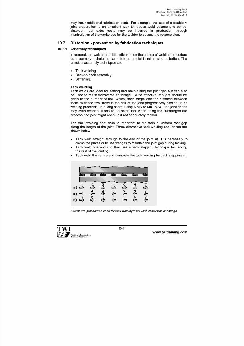
7/22/2019 CSWIP 3.2 LATEST WIS10-Mar-2011
http://slidepdf.com/reader/full/cswip-32-latest-wis10-mar-2011 114/303

7/22/2019 CSWIP 3.2 LATEST WIS10-Mar-2011
http://slidepdf.com/reader/full/cswip-32-latest-wis10-mar-2011 115/303
Rev 1 January 2011Residual Stress and Distortion
Copyright TWI Ltd 2011
www.twitraining.com 10-12
Directional tacking is a useful technique for controlling the joint gap, forexample closing a joint gap which is (or has become) too wide.
When tack welding, it is important that tacks which are to be fused into themain weld, are produced to an approved procedure using appropriately
qualified welders. The procedure may require preheat and an approvedconsumable as specified for the main weld. Removal of the tacks alsoneeds careful control to avoid causing defects in the component surface.
Back-to-back assemblyBy tack welding or clamping two identical components back-to-back,welding of both components can be balanced around the neutral axis of thecombined assembly (see a) on next page). It is recommended that theassembly is stress-relieved before separating the components. If stress-relieving is not done, it may be necessary to insert wedges between thecomponents (b) on next page) so when the wedges are removed, the parts
will move back to the correct shape or alignment.
Back-to-back assembly to control distortion when welding two identicalcomponents:a) Assemblies tacked together before welding.
b) Use of wedges for components that distort on separation after welding.

7/22/2019 CSWIP 3.2 LATEST WIS10-Mar-2011
http://slidepdf.com/reader/full/cswip-32-latest-wis10-mar-2011 116/303

7/22/2019 CSWIP 3.2 LATEST WIS10-Mar-2011
http://slidepdf.com/reader/full/cswip-32-latest-wis10-mar-2011 117/303
Rev 1 January 2011Residual Stress and Distortion
Copyright TWI Ltd 2011
www.twitraining.com 10-14
is more consistent, simple techniques such as pre-setting are more effectivein controlling angular distortion.
Welding techniqueGeneral rules for preventing distortion are:
Keep the weld (fillet) to the minimum specified size.
Use balanced welding about the neutral axis.
Keep the time between runs to a minimum.
Angular distortion of the joint as determined by the number of runs in the fillet weld.
In the absence of restraint, angular distortion in both fillet and butt joints willbe a function of the joint geometry, weld size and the number of runs for agiven cross-section. Angular distortion (measured in degrees) as a functionof the number of runs for a 10mm leg length fillet weld is shown above.
If possible, balanced welding around the neutral axis should be done, forexample on double-sided fillet joints, by two people welding simultaneously.In butt joints, the run order may be crucial in that balanced welding can beused to correct angular distortion as it develops.

7/22/2019 CSWIP 3.2 LATEST WIS10-Mar-2011
http://slidepdf.com/reader/full/cswip-32-latest-wis10-mar-2011 118/303
Rev 1 January 2011Residual Stress and Distortion
Copyright TWI Ltd 2011
www.twitraining.com 10-15
Use of welding direction to control distortion:a) Back-step welding;b) Skip welding.
Welding sequenceThe welding sequence, or direction, of welding is important and should betowards the free end of the joint. For long welds, the whole of the weld is notcompleted in one direction. Short runs, for example using the back-step orskip welding technique, are very effective in distortion control (see above).
Back-step welding involves depositing short adjacent weld lengths in theopposite direction to the general progression (see above).
Skip welding is laying short weld lengths in a pre-determined, evenlyspaced, sequence along the seam (b) in above figure). Weld lengths and
the spaces between them are generally equal to the natural run-outlength of one electrode. The direction of deposit for each electrode is thesame, but it is not necessary for the welding direction to be opposite tothe direction of general progression.
10.7.3 Best practice
The following fabrication techniques are used to control distortion:
Using tack welds to set-up and maintain the joint gap.
Identical components welded back-to-back so welding can be balanced
about the neutral axis. Attachment of longitudinal stiffeners to prevent longitudinal bowing in
butt welds of thin plate structures.
Where there is choice of welding procedure, process and techniqueshould aim to deposit the weld metal as quickly as possible; MIG/MAG inpreference to MMA or gas welding and mechanised rather than manualwelding.
In long runs, the whole weld should not be completed in one direction;back-step or skip welding techniques should be used.
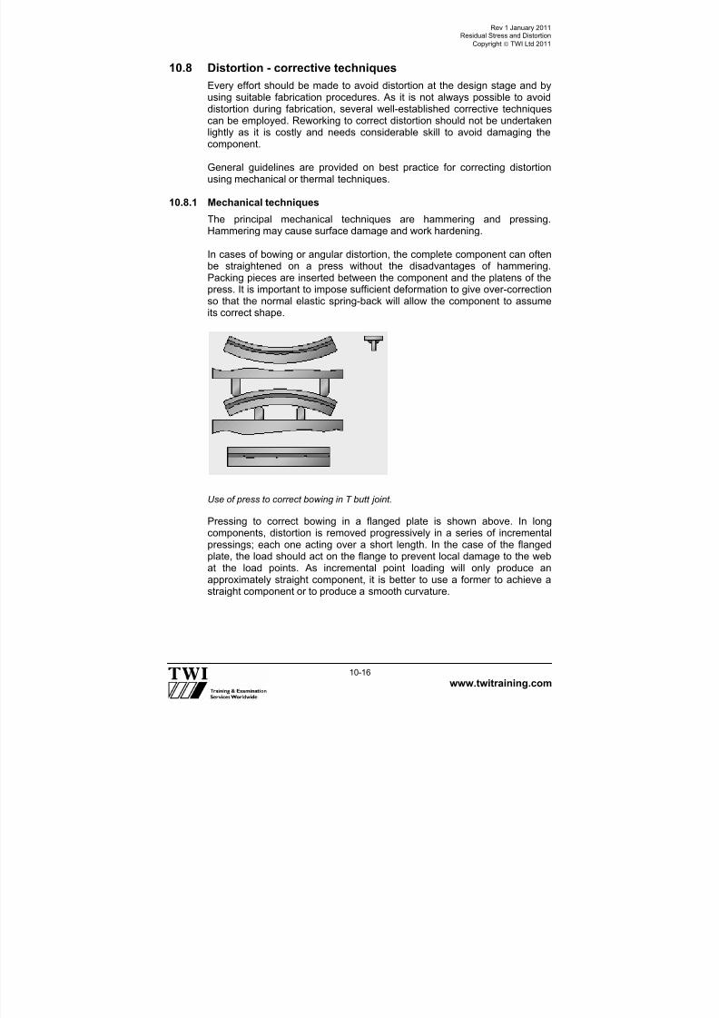
7/22/2019 CSWIP 3.2 LATEST WIS10-Mar-2011
http://slidepdf.com/reader/full/cswip-32-latest-wis10-mar-2011 119/303
Rev 1 January 2011Residual Stress and Distortion
Copyright TWI Ltd 2011
www.twitraining.com 10-16
10.8 Distortion - corrective techniques
Every effort should be made to avoid distortion at the design stage and byusing suitable fabrication procedures. As it is not always possible to avoiddistortion during fabrication, several well-established corrective techniques
can be employed. Reworking to correct distortion should not be undertakenlightly as it is costly and needs considerable skill to avoid damaging thecomponent.
General guidelines are provided on best practice for correcting distortionusing mechanical or thermal techniques.
10.8.1 Mechanical techniques
The principal mechanical techniques are hammering and pressing.Hammering may cause surface damage and work hardening.
In cases of bowing or angular distortion, the complete component can oftenbe straightened on a press without the disadvantages of hammering.Packing pieces are inserted between the component and the platens of thepress. It is important to impose sufficient deformation to give over-correctionso that the normal elastic spring-back will allow the component to assumeits correct shape.
Use of press to correct bowing in T butt joint.
Pressing to correct bowing in a flanged plate is shown above. In longcomponents, distortion is removed progressively in a series of incrementalpressings; each one acting over a short length. In the case of the flangedplate, the load should act on the flange to prevent local damage to the webat the load points. As incremental point loading will only produce anapproximately straight component, it is better to use a former to achieve astraight component or to produce a smooth curvature.

7/22/2019 CSWIP 3.2 LATEST WIS10-Mar-2011
http://slidepdf.com/reader/full/cswip-32-latest-wis10-mar-2011 120/303
Rev 1 January 2011Residual Stress and Distortion
Copyright TWI Ltd 2011
www.twitraining.com 10-17
Best practice for mechanical straighteningThe following should be adopted when using pressing techniques to removedistortion:
Use packing pieces which will over correct the distortion so that spring-
back will return the component to the correct shape. Check that the component is adequately supported during pressing to
prevent buckling.
Use a former (or rolling) to achieve a straight component or produce acurvature.
As unsecured packing pieces may fly out from the press, the followingsafe practice must be adopted:Bolt the packing pieces to the platen.Place a metal plate of adequate thickness to intercept the missile.Clear personnel from the hazard area.
10.8.2 Thermal techniques
The basic principle behind thermal techniques is to create sufficiently highlocal stresses so that, on cooling, the component is pulled back into shape.
Localised heating to correct distortion.
This is achieved by locally heating the material to a temperature whereplastic deformation will occur as the hot, low yield strength material tries toexpand against the surrounding cold, higher yield strength metal. On coolingto room temperature the heated area will attempt to shrink to a smaller sizethan before heating. The stresses generated thereby will pull the componentinto the required shape (see above).
Local heating is, therefore, a relatively simple but effective means ofcorrecting welding distortion. Shrinkage level is determined by size, number,location and temperature of the heated zones. Thickness and plate sizedetermines the area of the heated zone. Number and placement of heatingzones are largely a question of experience. For new jobs, tests will often beneeded to quantify the level of shrinkage.
Spot, line, or wedge-shaped heating techniques can all be used in thermalcorrection of distortion.
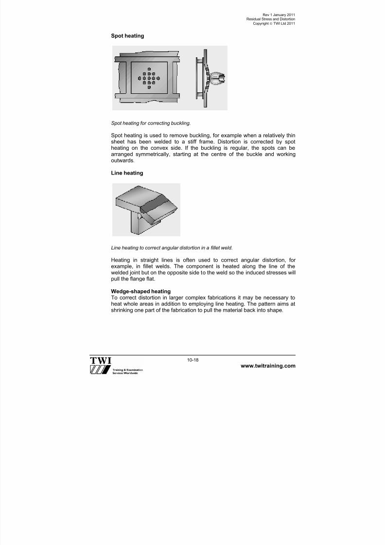
7/22/2019 CSWIP 3.2 LATEST WIS10-Mar-2011
http://slidepdf.com/reader/full/cswip-32-latest-wis10-mar-2011 121/303
Rev 1 January 2011Residual Stress and Distortion
Copyright TWI Ltd 2011
www.twitraining.com 10-18
Spot heating
Spot heating for correcting buckling.
Spot heating is used to remove buckling, for example when a relatively thinsheet has been welded to a stiff frame. Distortion is corrected by spotheating on the convex side. If the buckling is regular, the spots can bearranged symmetrically, starting at the centre of the buckle and workingoutwards.
Line heating
Line heating to correct angular distortion in a fillet weld.
Heating in straight lines is often used to correct angular distortion, forexample, in fillet welds. The component is heated along the line of thewelded joint but on the opposite side to the weld so the induced stresses willpull the flange flat.
Wedge-shaped heatingTo correct distortion in larger complex fabrications it may be necessary toheat whole areas in addition to employing line heating. The pattern aims atshrinking one part of the fabrication to pull the material back into shape.

7/22/2019 CSWIP 3.2 LATEST WIS10-Mar-2011
http://slidepdf.com/reader/full/cswip-32-latest-wis10-mar-2011 122/303

7/22/2019 CSWIP 3.2 LATEST WIS10-Mar-2011
http://slidepdf.com/reader/full/cswip-32-latest-wis10-mar-2011 123/303
Rev 1 January 2011Residual Stress and Distortion
Copyright TWI Ltd 2011
www.twitraining.com 10-20
General precautionsThe dangers of using thermal straightening techniques are the risk of over-shrinking too large an area or causing metallurgical changes by heating totoo high a temperature. As a general rule, when correcting distortion insteels the temperature of the area should be restricted to approximately to
600-650°C - dull red heat.
If the heating is interrupted, or the heat lost, the operator must allow themetal to cool and then begin again.
Best practice for distortion correction by thermal heatingThe following should be adopted when using thermal techniques to removedistortion:
Use spot heating to remove buckling in thin sheet structures.
Other than in spot heating of thin panels, use a wedge-shaped heating
technique.
Use line heating to correct angular distortion in plate.
Restrict the area of heating to avoid over-shrinking the component.
Limit the temperature to 600-650°C (dull red heat) in steels to preventmetallurgical damage.
In wedge heating, heat from the base to the apex of the wedge,penetrate evenly through the plate thickness and maintain an eventemperature.

7/22/2019 CSWIP 3.2 LATEST WIS10-Mar-2011
http://slidepdf.com/reader/full/cswip-32-latest-wis10-mar-2011 124/303
Section 11
Weldability of Steels

7/22/2019 CSWIP 3.2 LATEST WIS10-Mar-2011
http://slidepdf.com/reader/full/cswip-32-latest-wis10-mar-2011 125/303
Rev 1 January 2011Weldability of Steels
Copyright TWI Ltd 2011
www.twitraining.com 11-1
11 Weldability of Steels
11.1 Introduction
The term weldability simply means the ability to be welded and many typesof steel that are weldable have been developed for a wide range ofapplications.
However, it is the ease or difficulty of making a weld with suitable propertiesand free from defects which determines whether steels are considered ashaving ‘good weldability’ or said to have poor weldability. A steel is usuallysaid to have poor weldability if it is necessary take special precautions toavoid a particular type of imperfection. Another reason may be the need toweld within a very narrow range of parameters to achieve propertiesrequired for the joint.
11.2 Factors that affect weldability A number of inter-related factors determine whether a steel is said to havegood or poor weldability. These are:
Actual chemical composition.
Weld joint configuration.
Welding process to be used.
Properties required from the weldments.
For steels with poor weldability it is particularly necessary to ensure that:
Welding procedure specifications give welding conditions that do notcause cracking but achieve the specified properties.
Welders work strictly in accordance with the specified weldingconditions.
Welding inspectors regularly monitor welders to ensure they are workingstrictly in accordance the WPSs.
Having a good understanding of the characteristics, causes, and ways ofavoiding imperfections in steel weldments should enable welding inspectorsto focus attention on the most influential welding parameters when steels
with poor weldability are being used.
11.3 Hydrogen cracking
During fabrication by welding, cracks can occur in some types of steel, dueto the presence of hydrogen. The technical name for this type of cracking ishydrogen induced cold cracking (HICC) but it is often referred to by othernames that describe various characteristics of hydrogen cracks:
Cold cracking - cracks occur when the weld has cooled down.
HAZ cracking - cracks tend to occur mainly in the HAZ.

7/22/2019 CSWIP 3.2 LATEST WIS10-Mar-2011
http://slidepdf.com/reader/full/cswip-32-latest-wis10-mar-2011 126/303
Rev 1 January 2011Weldability of Steels
Copyright TWI Ltd 2011
www.twitraining.com 11-2
Delayed cracking - cracks may occur some time after welding hasfinished (possibly up to ~48h).
Underbead cracking - cracks occur in the HAZ beneath a weld bead.
Although most hydrogen cracks occur in the HAZ, there are circumstances
when they may form in weld metal.
Figure 1 shows typical locations of HAZ hydrogen cracks.
Figure 2 shows hydrogen crack in the HAZ of a fillet weld.
11.3.1 Factors influencing susceptibility to hydrogen cracking
Hydrogen cracking in the HAZ of a steel occurs when 4 conditions exist atthe same time:
Hydrogen level > 15ml/100g of weld metal depositedStress > 0.5 of the yield stressTemperature < 300
0C
Susceptible microstructure > 400HV hardness
These four conditions (four factors) are mutually interdependent so that theinfluence of one condition (its’ active level) depends on how active theothers three factors are.
11.3.2 Cracking mechanism
Hydrogen (H) can enter the molten weld metal when hydrogen containingmolecules are broken down into H atoms in the welding arc.
Because H atoms are very small they can move about (diffuse) in solid steeland while weld metal is hot they can diffuse to the weld surface and escapeinto the atmosphere.
However, at lower temperatures H cannot diffuse as quickly and if theweldment cools down quickly to ambient temperature H will become trapped- usually the HAZ.

7/22/2019 CSWIP 3.2 LATEST WIS10-Mar-2011
http://slidepdf.com/reader/full/cswip-32-latest-wis10-mar-2011 127/303
Rev 1 January 2011Weldability of Steels
Copyright TWI Ltd 2011
www.twitraining.com 11-3
If the HAZ has a susceptible microstructure – indicated by being relativelyhard and brittle, there are also relatively high tensile stresses in theweldment then H cracking can occur.
The precise mechanism that causes cracks to form is complex but H is
believed to cause embrittlement of regions of the HAZ so that high-localisedstresses cause cracking rather than plastic straining.
11.3.3 Avoiding HAZ hydrogen cracking
Because the factors that cause cracking are interdependent, and each needto be at an active level at the same time, cracking can be avoided byensuring that at least one of the four factors is not active during welding.
Methods that can be used to minimise the influence of each of the fourfactors are considered in the following sub-sections.
HydrogenThe principal source of hydrogen is moisture (H2O) and the principal sourceof moisture is welding flux. Some fluxes contain cellulose and this can be avery active source of hydrogen.
Welding processes that do not require flux can be regarded as low hydrogenprocesses.
Other sources of hydrogen are moisture present in rust or scale, and oilsand greases (hydrocarbons).
Reducing the influence of hydrogen is possible by:
Ensuring that fluxes (coated electrodes, flux-cored wires and SAWfluxes) are low in H when welding commences.
Low H electrodes must be either baked & then stored in a hot holdingoven or supplied in vacuum-sealed packages.
Basic agglomerated SAW fluxes should be kept in a heated silo beforeissue to maintain their as-supplied, low moisture, condition.
Check the diffusible hydrogen content of the weld metal (sometimes it isspecified on the test certificate).
Ensuring that a low H condition is maintained throughout welding by notallowing fluxes to pick-up moisture from the atmosphere.
Low hydrogen electrodes must be issued in small quantities and theexposure time limited; heated ‘quivers’ facilitate this control.
Flux-cored wire spools that are not seamless should be covered orreturned to a suitable storage condition when not in use.
Basic agglomerated SAW fluxes should be returned to the heated silowhen welding is not continuous.
Check the amount of moisture present in the shielding gas by checking
the dew point (must be bellow -60C).

7/22/2019 CSWIP 3.2 LATEST WIS10-Mar-2011
http://slidepdf.com/reader/full/cswip-32-latest-wis10-mar-2011 128/303
Rev 1 January 2011Weldability of Steels
Copyright TWI Ltd 2011
www.twitraining.com 11-4
Ensuring that the weld zone is dry and free from rust/scale andoil/grease.
Tensile stressThere are always tensile stresses acting on a weld because there are
always residual stresses from welding.
The magnitude of the tensile stresses is mainly dependent on the thicknessof the steel at the joint, heat input, joint type, and size and weight of thecomponents being welded.
Tensile stresses in highly restrained joints may be as high as the yieldstrength of the steel and this is usually the case in large components withthick joints and it is not a factor that can easily be controlled.
The only practical ways of reducing the influence of residual stresses may
be by:
Avoiding stress concentrations due to poor fit-up.
Avoiding poor weld profile (sharp weld toes).
Applying a stress-relief heat treatment after welding.
Increasing the travel speed as practicable in order to reduce the heatinput.
Keeping weld metal volume to an as low level as possible.
These measures are particularly important when welding some low alloy
steels that have particularly sensitivity to hydrogen cracking.
Susceptible HAZ microstructure A susceptible HAZ microstructure is one that contains a relatively highproportion of hard brittle phases of steel - particularly martensite.
The HAZ hardness is a good indicator of susceptibility and when it exceedsa certain value a particular steel is considered to be susceptible. For C andC-Mn steels this hardness value is ~ 350HV and susceptibility to H crackingincreases as hardness increases above this value.
The maximum hardness of an HAZ is influenced by:
Chemical composition of the steel.
Cooling rate of the HAZ after each weld run is made.
For C and C-Mn steels a formula has been developed to assess how thechemical composition will influence the tendency for significant HAZhardening - the carbon equivalent value (CEV) formula.
7/22/2019 CSWIP 3.2 LATEST WIS10-Mar-2011
http://slidepdf.com/reader/full/cswip-32-latest-wis10-mar-2011 129/303
Rev 1 January 2011Weldability of Steels
Copyright TWI Ltd 2011
www.twitraining.com 11-5
The CEV formula most widely used (and adopted by IIW) is:
CEViiw = % C + %Mn + %Cr + %Mo + %V + %Ni + %Cu6 5 15
The CEV of a steel is calculated by inserting the material test certificatevalues shown for chemical composition into the formula. The higher theCEV of a steel the greater its susceptibility to HAZ hardening and thereforethe greater the susceptibility to H cracking.
The element with most influence on HAZ hardness is carbon. The faster therate of HAZ cooling after each weld run, the greater the tendency forhardening.
Cooling rate tends to increase as:
Heat input decreases (lower energy input). Joint thickness increases (bigger heat sink).
Avoiding a susceptible HAZ microstructure (for C and C-Mn steels) requires:
Procuring steel with a CEV that is at the low-end of the range for thesteel grade(limited scope of effectiveness).
Using moderate welding heat input so that the weld does not cool quickly(and give HAZ hardening).
Applying pre-heat so that the HAZ cools more slowly (and does not show
significant HAZ hardening); in multi-run welds, maintain a specificinterpass temperature.
For low alloy steels, with additions of elements such as Cr, Mo and V, theCEV formula is not applicable and so must not be used to judge thesusceptibility to hardening. The HAZ of these steels will always tend to berelatively hard regardless of heat input and pre-heat and so this is a ‘factor’that cannot be effectively controlled to reduce the risk of H cracking. This isthe reason why some of the low alloy steels have greater tendency to showhydrogen cracking than in weldable C and C-Mn steels, which enable HAZhardness to be controlled.
Weldment at low temperatureWeldment temperature has a major influence on susceptibility to crackingmainly by influencing the rate at which H can move (diffuse) through theweld and HAZ. While a weld is relatively warm (>~300°C) H will diffuse quiterapidly and escape into the atmosphere rather than be trapped and causeembrittlement.

7/22/2019 CSWIP 3.2 LATEST WIS10-Mar-2011
http://slidepdf.com/reader/full/cswip-32-latest-wis10-mar-2011 130/303
Rev 1 January 2011Weldability of Steels
Copyright TWI Ltd 2011
www.twitraining.com 11-6
Reducing the influence of low weldment temperature (and the risk oftrapping H in the weldment) can be effected by:
Applying a suitable pre-heat temperature (typically 50 to ~250°C).
Preventing the weld from cooling down quickly after each pass by
maintaining the preheat and the specific interpass temperature duringwelding.
Maintaining the pre-heat temperature (or raising it to ~250°C) whenwelding has finished and holding the joint at this temperature for anumber of hours (minimum 2) to facilitate the escape of H (called post-heat *).
*Post-heat must not be confused with PWHT at a temperature ~600°C.
11.3.4 Hydrogen cracking in weld metal
Hydrogen cracks can form in steel weld metal under certain circumstances.The mechanism of cracking, and identification of all the influencing factors,is less clearly understood than for HAZ cracking but it can occur whenwelding conditions cause H to become trapped in weld metal rather than inHAZ. However it is recognised that welds in higher strength materials,thicker sections and using large beads are the most common areas whereproblems arise.
Hydrogen cracks in weld metal usually lie at 45° to the direction of principaltensile stress in the weld metal and this is usually the longitudinal axis of theweld (Figure 3). In some cases the cracks are of a V formation, hence an
alternative name chevron cracking.
There are not any well-defined rules for avoiding weld metal hydrogencracks apart from:
Ensure a low hydrogen welding process is used.
Apply preheat and maintain a specific interpass temperature.
BS EN 1011-2 entitled Welding – Recommendations for welding of metallicmaterials – Part 2: Arc welding of ferritic steels gives in Annex C practicalguidelines about how to avoid H cracking. Practical controls are basedprincipally on the application of pre-heat and control of potential Hassociated with the welding process.
11.4 Solidification cracking
The technically correct name for cracks that form during weld metalsolidification is solidification cracks but other names are sometimes usedwhen referring to this type of cracking.

7/22/2019 CSWIP 3.2 LATEST WIS10-Mar-2011
http://slidepdf.com/reader/full/cswip-32-latest-wis10-mar-2011 131/303

7/22/2019 CSWIP 3.2 LATEST WIS10-Mar-2011
http://slidepdf.com/reader/full/cswip-32-latest-wis10-mar-2011 132/303
Rev 1 January 2011Weldability of Steels
Copyright TWI Ltd 2011
www.twitraining.com 11-8
Sulphur and copper are elements that can make steel weld metal sensitiveto solidification cracking if they are present in the weld at relatively highlevels. Sulphur contamination may lead to the formation of iron sulphidesthat remain liquid when the bead has cooled down as low as ~980°C,whereas bead solidification starts at above 1400°C.
The source of sulphur may be contamination by oil or grease or it could bepicked up from the less refined parent steel being welded by dilution into theweld.Copper contamination in weld metal can be similarly harmful because it haslow solubility in steel and can form films that are still molten at ~1100°C. Avoiding solidification cracking (of an otherwise non-sensitive weld metal)requires the avoidance of contamination with potentially harmful materialsby ensuring:
Weld joints are thoroughly cleaned immediately before welding.
Any copper containing welding accessories are suitable/in suitablecondition - such as backing-bars and contact tips used for GMAW,FCAW and SAW.
Unfavourable welding conditionsUnfavourable welding conditions are those that encourage weld beads tosolidify so that low melting point films become trapped at the centre of asolidifying weld bead and become the weak zones for easy crack formation.
Figure 5 shows a weld bead that has solidified using unfavourable welding
conditions associated with centreline solidification cracking.
The weld bead has a cross-section that is quite deep and narrow – a width-to-depth ratio <~2 and the solidifying dendrites have pushed the lowermelting point liquid to the centre of the bead where it has become trapped.Since the surrounding material is shrinking as a result of cooling, this filmwould be subjected to tensile stress, which leads to cracking.
In contrast, Figure 6 shows a bead that has a width-to-depth ratio that is>>2. This bead shape shows lower melting point liquid pushed ahead of thesolidifying dendrites but it does not become trapped at the bead centre.
Thus, even under tensile stresses resulting from cooling, this film is self-healing and cracking is avoided.
SAW and spray-transfer GMAW are more likely to give weld beads with anunfavourable width-to-depth ratio than the other arc welding processes. Also, electron beam and laser welding processes are extremely sensitive tothis kind of cracking as a result of the deep, narrow beads produced.
Avoiding unfavourable welding conditions that lead to centrelinesolidification cracking (of weld metals with sensitive compositions) mayrequire significant changes to welding parameters, such as reducing the:
7/22/2019 CSWIP 3.2 LATEST WIS10-Mar-2011
http://slidepdf.com/reader/full/cswip-32-latest-wis10-mar-2011 133/303
Rev 1 January 2011Weldability of Steels
Copyright TWI Ltd 2011
www.twitraining.com 11-9
Welding current (to give a shallower bead).and
Welding speed (to give a wider weld bead).
Avoiding unfavourable welding conditions that lead to crater cracking of a
sensitive weld metal requires changes to the technique used at the end of aweld when the arc is extinguished, such as:
For TIG welding, use a current slope-out device so that the current, andweld pool depth gradually reduce before the arc is extinguished (givesmore favourable weld bead width-to-depth ratio). It is also a commonpractice to backtrack the bead slightly before breaking the arc orlengthen the arc gradually to avoid crater cracks.
For TIG welding, modify weld pool solidification mode by feeding the fillerwire into the pool until solidification is almost complete and avoiding aconcave crater.
For MMA, modify the weld pool solidification mode by reversing thedirection of travel at the end of the weld run so that crater is filled.
11.5 Lamellar tearing
Lamellar tearing is a type of cracking that only occurs in steel plate or otherrolled products underneath a weld.
Characteristics of lamellar tearing are:
Cracks only occur in the rolled products eg plate and sections.
Most common in C-Mn steels.
Cracks usually form close to, but just outside, the HAZ.
Cracks tend to lie parallel to surface of the material (and the fusionboundary of the weld), having a stepped aspect.
The above characteristics can be seen in Figure 7a.
11.5.1 Factors influencing susceptibility to lamellar tearing
Lamellar tearing occurs when two conditions exist at the same time:
A susceptible rolled plate is used to make a weld joint. High stresses act in the through-thickness direction of the susceptible
material (known as the short-transverse direction).
Susceptible rolled plate A material that is susceptible to lamellar tearing has very low ductility in thethrough-thickness direction (short-transverse direction) and is only able toaccommodate the residual stresses from welding by tearing rather than byplastic straining.

7/22/2019 CSWIP 3.2 LATEST WIS10-Mar-2011
http://slidepdf.com/reader/full/cswip-32-latest-wis10-mar-2011 134/303
Rev 1 January 2011Weldability of Steels
Copyright TWI Ltd 2011
www.twitraining.com 11-10
Low through-thickness ductility in rolled products is caused by the presenceof numerous non-metallic inclusions in the form of elongated stringers. Theinclusions form in the ingot but are flattened and elongated during hot rollingof the material.
Non-metallic inclusions associated with lamellar tearing are principallymanganese sulphides and manganese silicates.
High through-thickness stressWeld joints that are T, K and Y configurations end up with a tensileresidual stress component in the through-thickness direction.
The magnitude of the through-thickness stress increases as the restraint(rigidity) of the joint increases. Section thickness and size of weld are themain influencing factors and it is in thick section, full penetration T, K and Y joints that lamellar tearing is more likely to occur.
11.5.2 Cracking mechanism
High stresses in the through-thickness direction, that are present as weldingresidual stresses, because the inclusion stringers to open-up (de-cohese)and the thin ligaments between individual de-cohesed inclusions then tearand produce a stepped crack.
Figure 11b shows a typical step-like lamellar tear.
11.5.3 Avoiding lamellar tearing
Lamellar tearing can be avoided by reducing the influence of one, or both, ofthe factors.
Susceptible rolled plateEN 10164 (Steel products with improved deformation propertiesperpendicular to the surface of the product – Technical delivery conditions)gives guidance on the procurement of plate to resist lamellar tearing.
Resistance to lamellar tearing can be evaluated by means of tensile testpieces taken with their axes perpendicular to the plate surface (the through-thickness direction). Through-thickness ductility is measured as the %reduction of area (%R of A) at the point of fracture of the tensile test piece(Figure 8).
The greater the measured %R of A, the greater the resistance to lamellartearing. Values in excess of ~20% indicate good resistance even in veryhighly constrained joints.

7/22/2019 CSWIP 3.2 LATEST WIS10-Mar-2011
http://slidepdf.com/reader/full/cswip-32-latest-wis10-mar-2011 135/303
Rev 1 January 2011Weldability of Steels
Copyright TWI Ltd 2011
www.twitraining.com 11-11
Reducing the susceptibility of rolled plate to lamellar tearing can beachieved by ensuring that it has good through-thickness ductility by:
Using clean steel that has low sulphur content (<~0.015%) andconsequently has relatively few inclusions.
Procuring steel plate that has been subjected to through-thicknesstensile testing to demonstrate good through-thickness ductility (as EN10164).
Through-thickness stressThrough thickness stress in T, K and Y joints is principally the residualstress from welding, although the additional service stress may have someinfluence.
Reducing the magnitude of through-thickness stresses for a particular weld joint would require modification to the joint, in some way and so may not
always be practical because of the need to satisfy design requirements.However, methods that could be considered are:
Reducing the size of the weld by:
Using a partial penetration butt weld instead of full-penetration.
Using fillet welds instead of a full, or a partial pen butt weld (Figure 11.8).
By applying a buttering layer of weld metal to the surface of asusceptible plate so that the highest through-thickness strain is locatedin the weld metal and not the susceptible plate (Figure 11.9).
Changing the joint design – such as using a forged or extruded
intermediate piece so that the susceptible plate does not experiencethrough-thickness stress (Figure 11.10).

7/22/2019 CSWIP 3.2 LATEST WIS10-Mar-2011
http://slidepdf.com/reader/full/cswip-32-latest-wis10-mar-2011 136/303
Rev 1 January 2011Weldability of Steels
Copyright TWI Ltd 2011
www.twitraining.com 11-12
Figure 11.0 Typical locations of hydrogen induced cold cracks.
Figure 11.1 Hydrogen induced cold crack that initiated the HAZ at the toe of a filletweld.

7/22/2019 CSWIP 3.2 LATEST WIS10-Mar-2011
http://slidepdf.com/reader/full/cswip-32-latest-wis10-mar-2011 137/303
Rev 1 January 2011Weldability of Steels
Copyright TWI Ltd 2011
www.twitraining.com 11-13
Figure 11.2a and ba) Plan view of a plate butt weld showing subsurface transverse cracks;b Longitudinal section X-Y of the above weld showing how the transverse cracksactually lie at 45° to the surface. They tend to remain within an individual weld runand may be in weld several layers. Their appearance in this orientation has givenrise to the name ‘chevron’ cracks (arrow shaped cracks).
Weld layers withcracks lying at 45°to X-Y axis
b)
Y
X
Transversecracksa)

7/22/2019 CSWIP 3.2 LATEST WIS10-Mar-2011
http://slidepdf.com/reader/full/cswip-32-latest-wis10-mar-2011 138/303
Rev 1 January 2011Weldability of Steels
Copyright TWI Ltd 2011
www.twitraining.com 11-14
Figure 11.3a) Solidification crack at the weld bean centre where columnar dendrites havetrapped some lower melting point liquidb) The weld bead does not have an ideal shape but it has solidified without thedendrites meeting ‘end-on’ and trapping lower melting point liquid thereby resistingsolidification cracking.
a
b

7/22/2019 CSWIP 3.2 LATEST WIS10-Mar-2011
http://slidepdf.com/reader/full/cswip-32-latest-wis10-mar-2011 139/303
Rev 1 January 2011Weldability of Steels
Copyright TWI Ltd 2011
www.twitraining.com 11-15
Figure 11.4 A weld bead with an unfavourable width-to-depth ratio. This isresponsible for liquid metal being pushed into the centre of the bead by theadvancing columnar dendrites and becoming the weak zone that is ruptured.
Figure 11.5 Weld bead with a favourable width-to-depth ratio. The dendrites push
the lowest melting point metal towards the surface at the centre of the bead centreand so it does not form a weak central zone.
‘
WW
DD
DDiirreeccttiioonn oof f ttrraavveell
W/D > ~2
(
WW
DD
DDiirreeccttiioonn oof f ttrraavveell
W/D < 2

7/22/2019 CSWIP 3.2 LATEST WIS10-Mar-2011
http://slidepdf.com/reader/full/cswip-32-latest-wis10-mar-2011 140/303
Rev 1 January 2011Weldability of Steels
Copyright TWI Ltd 2011
www.twitraining.com 11-16
Figure 11.6 a) Typical lamellar tear located just outside the visible HAZ b) Step-likecrack characteristic of a lamellar tear.
a)
Inclusionstringer
b)
Through-thickness
residual stressesfrom welding
De-cohesionof inclusion stringers
Crack propagation by tearingof ligaments between
‘de-cohesed’ inclusion stringers
HAZ
Fusion
boundary

7/22/2019 CSWIP 3.2 LATEST WIS10-Mar-2011
http://slidepdf.com/reader/full/cswip-32-latest-wis10-mar-2011 141/303
Rev 1 January 2011Weldability of Steels
Copyright TWI Ltd 2011
www.twitraining.com 11-17
Figure 11.7 Round tensile test piece taken with its axis in the short-transversedirection (through thickness of plate) to measure the % R. of A. and assess the plate’s resistance to lamellar tearing.
Figure 11.8 educing the effective size of a weld will reduce the through-thicknessstress on the susceptible plate and may be sufficient to reduce the risk of lamellartearing.
PPllaattee ssuur r f f aaccee
PPllaattee ssuur r f f aaccee
TThhr r oouugghh--tthhiicckknneessss tteennssiillee tteesstt ppiieeccee
RReedduuccttiioonn oof f ddiiaammeetteer r aatt ppooiinntt oof f
f f r r aaccttuur r ee
Susceptible plate Susceptible plate

7/22/2019 CSWIP 3.2 LATEST WIS10-Mar-2011
http://slidepdf.com/reader/full/cswip-32-latest-wis10-mar-2011 142/303
Rev 1 January 2011Weldability of Steels
Copyright TWI Ltd 2011
www.twitraining.com 11-18
Figure 11.9 Lamellar tearing can be avoided by changing the joint design.
Figure 11.10 Two layers of weld metal (usually by MMA) applied to susceptible plate before the T-butt weld is made.
Extruded sectionSusceptible plate
Weld metal ‘buttering’
Susceptible plate

7/22/2019 CSWIP 3.2 LATEST WIS10-Mar-2011
http://slidepdf.com/reader/full/cswip-32-latest-wis10-mar-2011 143/303
Section 12 Weld Fractures

7/22/2019 CSWIP 3.2 LATEST WIS10-Mar-2011
http://slidepdf.com/reader/full/cswip-32-latest-wis10-mar-2011 144/303
Rev 1 January 2011Weld Fractures
Copyright TWI Ltd 2011
www.twitraining.com 12-1
12 Weld Fractures
Welds may suffer three different fracture mechanisms:
Ductile.
Brittle. Fatigue.
Often a complete fracture of a weldment will be a combination of fracturetypes eg initially fatigue followed by final ductile fracture.
12.1 Ductile fractures
Occur in instances where the strength and the cross-sectional area of thematerial are insufficient to carry the applied load.
Such fractures are commonly seen on material and welding proceduretensile test specimens where failure is accompanied by yielding, stretchingand thinning as shown below.
The fracture edges are at 45° to the applied load and are known as shearlips.
12.2 Brittle fracture
Is a fast, unstable type of fracture which can lead to catastrophic failure.
The phenomenon was first identified during World War 2 when many Liberty
Ships broke in two for no apparent reason. Since that time many brittlefailures have occurred in bridges, boilers, pressure vessels etc sometimeswith loss of life and always with expensive damage.
The risk of brittle fracture increases;
As the temperature (ambient or operational) decreases.
With the type and increasing thickness of the material.
Where high levels of residual stresses are present.
In the presence of notches.
Increased strain rate ie speed of loading.

7/22/2019 CSWIP 3.2 LATEST WIS10-Mar-2011
http://slidepdf.com/reader/full/cswip-32-latest-wis10-mar-2011 145/303
Rev 1 January 2011Weld Fractures
Copyright TWI Ltd 2011
www.twitraining.com 12-2
Courtesy of Douglas E. Williams, P.E., Welding Handbook, Vol.1, Ninth Edition,reprinted by permission of the American Welding Society.
Eeffect of notch on a tensile specimen.
Distinguishing features of a brittle fracture are:
Surface is flat and at 90° to the applied load.
Will show little or no plastic deformation.
The surface will be rough and may be crystalline in appearance.
May show chevrons which will point back to the initiation source.

7/22/2019 CSWIP 3.2 LATEST WIS10-Mar-2011
http://slidepdf.com/reader/full/cswip-32-latest-wis10-mar-2011 146/303
Rev 1 January 2011Weld Fractures
Copyright TWI Ltd 2011
www.twitraining.com 12-3
Brittle fracture surface on a CTOD test piece.
12.3 Fatigue fracture
Fatigue fractures occur in situations where loading is of a cyclic nature andat stress levels well below the yield stress of the material.
Typically fatigue cracks will be found on bridges, cranes, aircraft and items
affected by out of balance or vibrating forces.
Initiation takes place from stress concentrations such as changes of section,arc- strikes, toes of welds. Even the best designed and made welds havesome degree of stress concentration.
As fatigue cracks take time firstly to initiate then to grow, this slowprogression allows such cracks to be found by regular inspection scheduleson those items known to be fatigue sensitive.
The growth rate of fatigue cracks is dependant on the loading and the
number of cycles. It is not time dependant
Fatigue failures are not restricted to any one type of material or temperaturerange. Stress-relief has little effect upon fatigue life.
Structures known to be at risk of fatigue failure are usually designed tocodes that acknowledge the risk and lays down the rules and calculations topredict its design life.
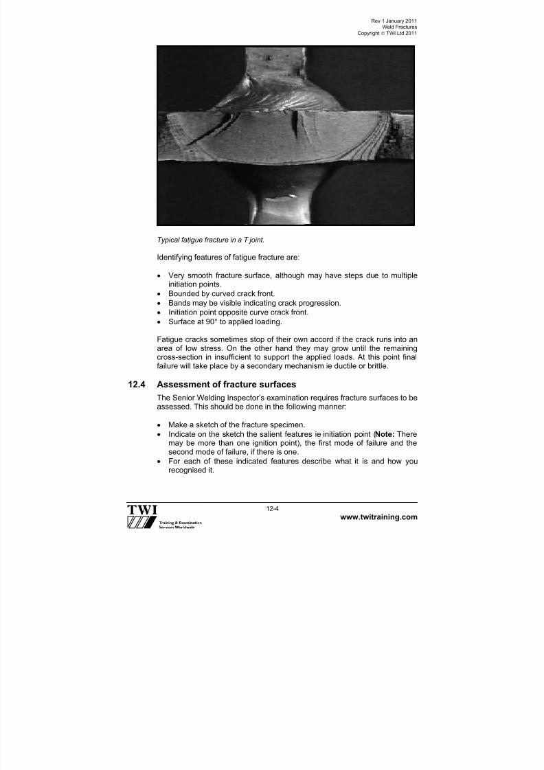
7/22/2019 CSWIP 3.2 LATEST WIS10-Mar-2011
http://slidepdf.com/reader/full/cswip-32-latest-wis10-mar-2011 147/303
Rev 1 January 2011Weld Fractures
Copyright TWI Ltd 2011
www.twitraining.com 12-4
Typical fatigue fracture in a T joint.
Identifying features of fatigue fracture are:
Very smooth fracture surface, although may have steps due to multiple
initiation points. Bounded by curved crack front.
Bands may be visible indicating crack progression.
Initiation point opposite curve crack front.
Surface at 90° to applied loading.
Fatigue cracks sometimes stop of their own accord if the crack runs into anarea of low stress. On the other hand they may grow until the remainingcross-section in insufficient to support the applied loads. At this point finalfailure will take place by a secondary mechanism ie ductile or brittle.
12.4 Assessment of fracture surfaces
The Senior Welding Inspector’s examination requires fracture surfaces to beassessed. This should be done in the following manner:
Make a sketch of the fracture specimen.
Indicate on the sketch the salient features ie initiation point (Note: Theremay be more than one ignition point), the first mode of failure and thesecond mode of failure, if there is one.
For each of these indicated features describe what it is and how yourecognised it.

7/22/2019 CSWIP 3.2 LATEST WIS10-Mar-2011
http://slidepdf.com/reader/full/cswip-32-latest-wis10-mar-2011 148/303
Section 13
Welding Symbols

7/22/2019 CSWIP 3.2 LATEST WIS10-Mar-2011
http://slidepdf.com/reader/full/cswip-32-latest-wis10-mar-2011 149/303
Rev 1 January 2011Welding Symbols
Copyright TWI Ltd 2011
www.twitraining.com 13-1
13 Welding Symbols
A weld joint can be represented on an engineering drawing by means of adetailed sketch showing every detail and dimension of the joint preparation -as shown below.
Single U preparation
While this method of representation gives comprehensive information, it canbe time-consuming and can also overburden the drawing.
An alternative method is to use a symbolic representation to specify therequired information - as shown below for the same joint detail.
Symbolic representation has following advantages:
Simple and quick to put on the drawing.
Does not over-burden the drawing.
No need for an additional view - all welding symbols can be put on the
main assembly drawing.
Symbolic representation has following disadvantages:
Can only be used for standard joints (eg BS EN ISO 9692).
There is not a way of giving precise dimensions for joint details.
Some training is necessary in order to interpret the symbols correctly.
8-12
R6
1-4mm
1-3mm

7/22/2019 CSWIP 3.2 LATEST WIS10-Mar-2011
http://slidepdf.com/reader/full/cswip-32-latest-wis10-mar-2011 150/303
Rev 1 January 2011Welding Symbols
Copyright TWI Ltd 2011
www.twitraining.com 13-2
13.1 Standards for symbolic representation of welded joints ondrawings
There are two principal standards that are used for welding symbols:
European StandardEN22553 – Welded, brazed and soldered joints – Symbolic representationon drawings.
American Standard AWS A2.4 – Standard Symbols for Welding, Brazing, and Non-destructiveExamination.
These standards are very similar in many respects, but there are also somemajor differences that need to be understood to avoid mis-interpretation.
Details of the European Standard are given in the following sub-sectionswith only brief information about how the American Standard differs from theEuropean Standard.
Elementary Welding SymbolsVarious types of weld joint are represented by a symbol that is intended tohelp interpretation by being similar to the shape of the weld to be made.
Examples of symbols used by EN 22553 are shown on following pages.

7/22/2019 CSWIP 3.2 LATEST WIS10-Mar-2011
http://slidepdf.com/reader/full/cswip-32-latest-wis10-mar-2011 151/303
Rev 1 January 2011Welding Symbols
Copyright TWI Ltd 2011
www.twitraining.com 13-3
13.2 Elementary welding symbols
Designation Illustration of joint preparation Symbol
Square butt weld
Single V butt weld
Single bevel butt weld
Single V butt weld withbroad root face
Single bevel butt weldwith broad root face
Single U butt weld
Single J butt weld
Fillet weld
Surfacing (cladding)
Backing run
(back or backing weld)
Backing bar

7/22/2019 CSWIP 3.2 LATEST WIS10-Mar-2011
http://slidepdf.com/reader/full/cswip-32-latest-wis10-mar-2011 152/303
Rev 1 January 2011Welding Symbols
Copyright TWI Ltd 2011
www.twitraining.com 13-4
13.3 Combination of elementary symbols
For symmetrical welds made from both sides, the applicable elementarysymbols are combined – as shown below.
Designation Illustration of joint preparation SymbolDouble V butteld (X weld)
Double bevel butteld (K weld)
Double U butteld
Double J butteld

7/22/2019 CSWIP 3.2 LATEST WIS10-Mar-2011
http://slidepdf.com/reader/full/cswip-32-latest-wis10-mar-2011 153/303
Rev 1 January 2011Welding Symbols
Copyright TWI Ltd 2011
www.twitraining.com 13-5
13.4 Supplementary symbols
Weld symbols may be complemented by a symbol to indicate the requiredshape of the weld.
Examples of supplementary symbols and how they are applied are givenbelow.
Designation Illustration of joint preparation Symbol
Flat (flush)single V buttweld
Convex doubleV butt weld
Concave filletweld
Flat (flush)single V buttweld with flat(flush) backingrun
Single V buttweld with broadroot face andbacking run
Fillet weld withboth toesblendedsmoothly
Note: If the weld symbol does not have a supplementary symbol then the
shape of the weld surface does not need to be indicated precisely.
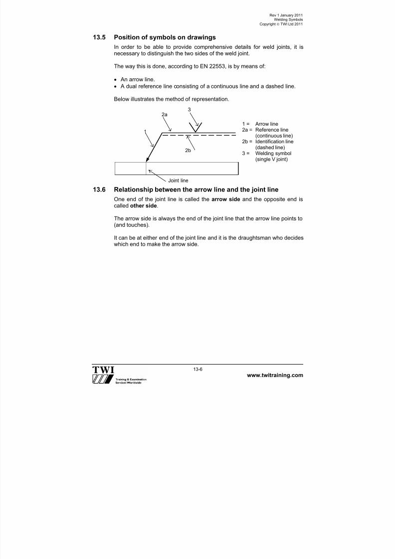
7/22/2019 CSWIP 3.2 LATEST WIS10-Mar-2011
http://slidepdf.com/reader/full/cswip-32-latest-wis10-mar-2011 154/303
Rev 1 January 2011Welding Symbols
Copyright TWI Ltd 2011
www.twitraining.com 13-6
13.5 Position of symbols on drawings
In order to be able to provide comprehensive details for weld joints, it isnecessary to distinguish the two sides of the weld joint.
The way this is done, according to EN 22553, is by means of:
An arrow line.
A dual reference line consisting of a continuous line and a dashed line.
Below illustrates the method of representation.
13.6 Relationship between the arrow line and the joint line
One end of the joint line is called the arrow side and the opposite end is
called other side.
The arrow side is always the end of the joint line that the arrow line points to(and touches).
It can be at either end of the joint line and it is the draughtsman who decideswhich end to make the arrow side.
Joint line
1
2a
2b
3
1 = Arrow line2a = Reference line
(continuous line)2b = Identification line(dashed line)
3 = Welding symbol(single V joint)

7/22/2019 CSWIP 3.2 LATEST WIS10-Mar-2011
http://slidepdf.com/reader/full/cswip-32-latest-wis10-mar-2011 155/303
Rev 1 January 2011Welding Symbols
Copyright TWI Ltd 2011
www.twitraining.com 13-7
Below illustrates these principles.
There are some conventions about the arrow line:
It must touch one end of the joint line.
It joins one end of the continuous reference line.
In case of a non-symmetrical joint, such as a single bevel joint, thearrow line must point towards the joint member that will have the weldpreparation put on to it (as shown below).
An example of how a single-bevel butt joint should be represented is shown
below.
13.7 Position of the reference line and position of the weldsymbol
The reference line should, wherever possible, be drawn parallel to thebottom edge of the drawing (or perpendicular to it).
For a non-symmetrical weld it is essential that the arrow side and other sideof the weld be distinguished. The convention for doing this is:
Symbols for the weld details required on the arrow side must be placedon the continuous line.
Symbols for the weld details on other side must be placed on the dashedline.
‘arrow side’
‘arrow side’
arrow line
‘other side’
arrow line
‘other side’
arrow line
‘arrow side’ ‘other side’
arrow line
‘other side’ ‘arrow side’

7/22/2019 CSWIP 3.2 LATEST WIS10-Mar-2011
http://slidepdf.com/reader/full/cswip-32-latest-wis10-mar-2011 156/303
Rev 1 January 2011Welding Symbols
Copyright TWI Ltd 2011
www.twitraining.com 13-8
13.8 Positions of the continuous line and the dashed line
EN 22553 allows the dashed line to be either above or below the continuousline – as shown below.
If the weld is a symmetrical weld then it is not necessary to distinguishbetween the two sides and EN 22553 states that the dashed line should beomitted. Thus, a single V butt weld with a backing run can be shown byeither of the four symbolic representations shown below.
Single V weld with a backing run.
Note: This flexibility with the position of the continuous and dashed lines is
an interim measure that EN 22553 allows so that old drawings (to theobsolete BS 499 Part 2, for example) can be conveniently converted toshow the EN method of representation.
or
Arrow side
Arrow side
Other side
Other side
Arrow side
Other side Arrow side
Other side
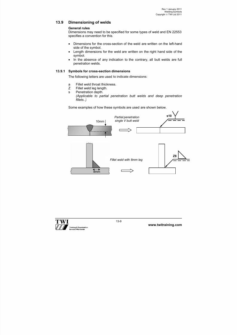
7/22/2019 CSWIP 3.2 LATEST WIS10-Mar-2011
http://slidepdf.com/reader/full/cswip-32-latest-wis10-mar-2011 157/303
Rev 1 January 2011Welding Symbols
Copyright TWI Ltd 2011
www.twitraining.com 13-9
13.9 Dimensioning of welds
General rulesDimensions may need to be specified for some types of weld and EN 22553specifies a convention for this.
Dimensions for the cross-section of the weld are written on the left-handside of the symbol.
Length dimensions for the weld are written on the right hand side of thesymbol.
In the absence of any indication to the contrary, all butt welds are fullpenetration welds.
13.9.1 Symbols for cross-section dimensions
The following letters are used to indicate dimensions:
a Fillet weld throat thickness.Z Fillet weld leg length.s Penetration depth.
(Applicable to partial penetration butt welds and deep penetrationfillets..)
Some examples of how these symbols are used are shown below.
10mm
Partial penetrationsingle V butt weld
s10
8mm
Z8
Fillet weld with 8mm leg

7/22/2019 CSWIP 3.2 LATEST WIS10-Mar-2011
http://slidepdf.com/reader/full/cswip-32-latest-wis10-mar-2011 158/303
Rev 1 January 2011Welding Symbols
Copyright TWI Ltd 2011
www.twitraining.com 13-10
13.9.2 Symbols for length dimensions
To specify weld length dimensions and, for intermittent welds the number ofindividual weld lengths (weld elements), the following letters are used: -
l Length of weld.
(e) Distance between adjacent weld elements.
n Number of weld elements.
The use of these letters is illustrated for the intermittent double-sided filletweld shown below.
Note: dashed line not required because it is a symmetrical weld.
a6Fillet weld with 6mm throat
6mm
n x l (e)
z n x l e
8
150mm
100mm
Plan view End view
Z8 3 150 (100)
Z8 z n l ( e)
z n l ( e) 3 150 (100)Z
Z z n l ( e)
z n l ( e)
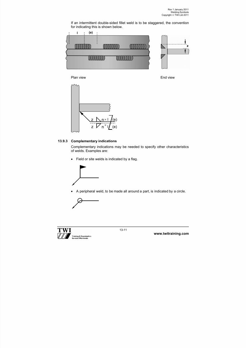
7/22/2019 CSWIP 3.2 LATEST WIS10-Mar-2011
http://slidepdf.com/reader/full/cswip-32-latest-wis10-mar-2011 159/303
Rev 1 January 2011Welding Symbols
Copyright TWI Ltd 2011
www.twitraining.com 13-11
If an intermittent double-sided fillet weld is to be staggered, the conventionfor indicating this is shown below.
Plan view End view
13.9.3 Complementary indications
Complementary indications may be needed to specify other characteristicsof welds. Examples are:
Field or site welds is indicated by a flag.
A peripheral weld, to be made all around a part, is indicated by a circle.
z n l (e)
zn
l (e)
l (e)
z

7/22/2019 CSWIP 3.2 LATEST WIS10-Mar-2011
http://slidepdf.com/reader/full/cswip-32-latest-wis10-mar-2011 160/303
Rev 1 January 2011Welding Symbols
Copyright TWI Ltd 2011
www.twitraining.com 13-12
13.10 Indication of the welding process
If required, the welding process is to be symbolised by a number writtenbetween the two branches of a fork at the end of the reference line – asshown below.
13.11 Other Information in the tail of the reference line
In addition to specifying the welding process, other information can beadded to an open tail (shown above) such as the NDT acceptance level the
working position and the filler metal type and EN 22553 defines thesequence that must be used for this information.
A closed tail can also be used into which reference to a specific instructioncan be added – as shown below.
13.12 Weld symbols in accordance with AWS 2.4
Many of the symbols and conventions that are specified by EN 22553 arethe same as those used by AWS.
The major differences are:
Only one reference line is used (a continuous line).
Symbols for weld details on the arrow side go underneath thereference line.
Symbols for weld details on the other side go on top of the reference
line.
111
Some welding process
designations
111 = MMA121 = SAW131 = MIG135 = MAG141 = TIG
WPS 014

7/22/2019 CSWIP 3.2 LATEST WIS10-Mar-2011
http://slidepdf.com/reader/full/cswip-32-latest-wis10-mar-2011 161/303
Rev 1 January 2011Welding Symbols
Copyright TWI Ltd 2011
www.twitraining.com 13-13
These differences are illustrated by the following example.
13.13 Drawing review
Drawings are often made by personnel not familiar with the relevant symbolrules which results in drawings that are difficult to interpret or ambiguous intheir intent.
As part of the CSWIP 3.2 examination candidates will need to demonstratetheir competence at interpreting such an engineering drawing in respect of
its welding symbols. To do this:
The candidate first needs to establish the symbol system being used.
Next study the views and part sections of the object so that it can bevisualised in its manufactured form.
For each of the designated symbols, draw a sketch of what the joint willlook like according to the symbol.
Next describe the joint in words, together with any supplementaryinformation, eg field weld, ground flush, welding process and otherplaces, etc. which has been given.
If any thing is wrong with the symbol such as the dashed line is missing,the symbol is the wrong way around, the described joint cannot be puton the material in the manner shown, write down the problem but do notsuggest how it should be made.
Arrow side
Other side

7/22/2019 CSWIP 3.2 LATEST WIS10-Mar-2011
http://slidepdf.com/reader/full/cswip-32-latest-wis10-mar-2011 162/303
Section 14
NDT

7/22/2019 CSWIP 3.2 LATEST WIS10-Mar-2011
http://slidepdf.com/reader/full/cswip-32-latest-wis10-mar-2011 163/303
Rev 1 January 2011NDT
Copyright TWI Ltd 2011
www.twitraining.com 14-1
14 NDT
IntroductionRadiographic, ultrasonic, dye-penetrant and magnetic particle methods arebriefly described below. The relative advantages and limitations of the
methods are discussed in terms of their applicability to the examination ofwelds.
14.1 Radiographic methods
In all cases radiographic methods as applied to welds involve passing abeam of penetrating radiation through the test object. The transmittedradiation is collected by some form of sensor, which is capable of measuringthe relative intensities of penetrating radiations impinging upon it. In mostcases this sensor will be a radiographic film; however the use of variouselectronic devices is on the increase. These devices facilitate so-called real
time radiography and examples may be seen in the security check area atmost airports. Digital technology has enabled the storing of radiographsusing computers. The present discussion is confined to film radiographysince this is still by far the most common method applied to welds.
14.1.1 Sources of penetrating radiation
Penetrating radiations may be generated from high-energy electron beams,in which case they are termed X rays, or from nuclear disintegrations
(atomic fission), in which case they are termed -rays. Other forms ofpenetrating radiation exist but they are of limited interest in weldradiography.
14.1.2 X rays
X rays used in the industrial radiography of welds generally have photonenergies in the range 30keV up to 20MeV. Up to 400keV they are generatedby conventional X ray tubes which dependant upon output may be suitablefor portable or fixed installations. Portability falls off rapidly with increasingkilovoltage and radiation output. Above 400keV X rays are produced usingdevices such as betatrons and linear accelerators. These devices are notgenerally suitable for use outside of fixed installations. All sources of X raysproduce a continuous spectrum of radiation, reflecting the spread of kinetic
energies of electrons within the electron beam. Low energy radiations aremore easily absorbed and the presence of low energy radiations, within theX ray beam, gives rise to better radiographic contrast and therefore better
radiographic sensitivity than is the case with -rays which are discussedbelow. Conventional X ray units are capable of performing high qualityradiography on steel of up to 60mm thickness, betatrons and linearaccelerators are capable of penetrating in excess of 300mm of steel.

7/22/2019 CSWIP 3.2 LATEST WIS10-Mar-2011
http://slidepdf.com/reader/full/cswip-32-latest-wis10-mar-2011 164/303
Rev 1 January 2011NDT
Copyright TWI Ltd 2011
www.twitraining.com 14-2
14.1.3 -rays
The early sources of -rays used in industrial radiography were in generalcomposed of naturally occurring radium. The activity of these sources wasnot very high, therefore they were physically rather large by modernstandards even for quite modest outputs of radiation and the radiographsproduced by them were not of a particularly high standard. Radium sourceswere also extremely hazardous to the user due to the production ofradioactive radon gas as a product of the fission reaction. Since the adventof the nuclear age it has been possible to artificially produce isotopes ofmuch higher specific activity than those occurring naturally and which do not
produce hazardous fission products. Unlike the X-ray sources -sources do
not produce a continuous distribution of quantum energies. -sourcesproduce a number of specific quantum energies which are unique for anyparticular isotope. Four isotopes are in common use for the radiography ofwelds; they are in ascending order of radiation energy: thulium 90, ytterbium
169, iridium 192 and cobalt 60. In terms of steel thulium 90 is useful up to athickness of 7mm or so, it’s energy is similar to that of 90keV X rays anddue to it’s high specific activity useful sources can be produced with physicaldimensions of less than 0.5mm. Ytterbium 169 has only fairly recentlybecome available as an isotope for industrial use, it’s energy is similar tothat of 120keV X rays and it is useful for the radiography of steel up toapproximately 12mm thickness. Iridium 192 is probably the most commonlyencountered isotopic source of radiation used in the radiographicexamination of welds, it has a relatively high specific activity and high outputsources with physical dimensions of 2-3mm are in common usage, it’senergy is approximately equivalent to that of 500 keV X rays and it is useful
for the radiography of steel in the thickness range 10-75mm. Cobalt 60 hasan energy approximating to that of 1.2MeV X rays, due this relatively highenergy suitable source containers are large and rather heavy. Cobalt 60sources are for this reason not fully portable. They are useful for theradiography of steel in the thickness range 40-150mm.
The major advantages of using isotopic sources over X rays are: a) Theincreased portability; b) The lack of the need for a power source; c) Lowerinitial equipment costs. Against this the quality of radiographs produced by
-ray techniques is inferior to that produced by X ray techniques, thehazards to personnel may be increased (if the equipment is not properlymaintained, or if the operating personnel have insufficient training) and dueto their limited useful lifespan new isotopes have to be purchased on a
regular basis (so that the operating costs of a -ray source may exceedthose of an X ray source).
14.1.4 Radiography of welds
Radiographic techniques depend upon detecting differences in absorption ofthe beam ie: changes in the effective thickness of the test object, in order toreveal defective areas. Volumetric weld defects such as slag inclusions(except in some special cases where the slag absorbs radiation to a greater
extent than does the weld metal) and various forms of gas porosity are

7/22/2019 CSWIP 3.2 LATEST WIS10-Mar-2011
http://slidepdf.com/reader/full/cswip-32-latest-wis10-mar-2011 165/303
Rev 1 January 2011NDT
Copyright TWI Ltd 2011
www.twitraining.com 14-3
easily detected by radiographic techniques due to the large negativeabsorption difference between the parent metal and the slag or gas. Planardefects such as cracks or lack of side wall or inter-run fusion are much lesslikely to be detected by radiography since such defects may cause little orno change in the penetrated thickness. Where defects of this type are likely
to occur other NDE techniques such as ultrasonic testing are preferable toradiography. This lack of sensitivity to planar defects makes radiography anunsuitable technique where a fitness-for-purpose approach is taken whenassessing the acceptability of a weld. However, film radiography produces apermanent record of the weld condition, which can be archived for futurereference; it also provides an excellent means of assessing the welder’sperformance and for these reasons it is often still the preferred method fornew construction.
Figure 14.0 X ray equipment. Figure 14.1 Gamma-ray equipment.
Figure 14.2 X ray of a welded seam showing porosity.

7/22/2019 CSWIP 3.2 LATEST WIS10-Mar-2011
http://slidepdf.com/reader/full/cswip-32-latest-wis10-mar-2011 166/303
Rev 1 January 2011NDT
Copyright TWI Ltd 2011
www.twitraining.com 14-4
14.1.5 Radiographic testing
Advantages Limitations
• Permanent record• Good for sizing non planar
defects/flaws• Can be used on all materials• Direct image of defects/flaws• Real-time imaging• Can be position inside pipe
(productivity)• Very good thickness
penetration available• No power required with
gamma
• Health hazard. Safety (important) •• CCllaassssiif f iieedd wwoor r kkeer r ss,, mmeeddiiccaallss r r eeqquuiir r eedd
•• SS
ee
nn
ssiittiivvee
ttoo
dd
ee
f f ee
cctt oo
r r iiee
nn
ttaa
ttiioo
nn
•• NNoott ggoooodd f f oor r ppllaannaar r ddeef f eecctt ddeetteeccttiioonn •• LLiimmiitteedd aabbiilliittyy ttoo ddeetteecctt f f iinnee ccr r aacckkss •• A Acccceessss ttoo bbootthh ssiiddeess r r eeqquuiir r eedd •• SSkkiilllleedd iinntteer r ppr r eettaattiioonn r r eeqquuiir r eedd •• RReellaattiivveellyy ssllooww •• HHiigghh ccaappiittaall oouuttllaayy aanndd r r uunnnniinngg ccoossttss •• IIssoottooppeess hhaavvee aa hhaallf f lliif f ee ((ccoosstt))
14.1.6 Ultrasonic methodsThe velocity of ultrasound in any given material is a constant for thatmaterial and ultrasonic beams travel in straight lines in homogeneousmaterials. When ultrasonic waves pass from a given material with a givensound velocity to a second material with different velocity refraction andreflection of the sound beam will occur at the boundary between the twomaterials. The same laws of physics apply equally to ultrasonic waves asthey do to light waves. Because ultrasonic waves are refracted at aboundary between two materials having different acoustic properties, probesmay be constructed which can beam sound into a material at (within certainlimits) any given angle. Because sound is reflected at a boundary betweentwo materials having different acoustic properties ultrasound is a useful toolfor the detection of weld defects. Because the velocity is a constant for anygiven material and because sound travels in a straight line (with the rightequipment) ultrasound can also be utilised to give accurate positionalinformation about a given reflector. Careful observation of the echo patternof a given reflector and its behaviour as the ultrasonic probe is movedtogether with the positional information obtained above and knowledge ofthe component history enables the experienced ultrasonic operator toclassify the reflector as say slag lack of fusion or a crack.
14.1.7 Equipment for ultrasonic testingEquipment for manual ultrasonic testing consists of:
A) A flaw detector comprising:
Pulse generator.
Adjustable time base generator with an adjustable delay control.
Cathode ray tube with fully rectified display.
Calibrated amplifier with a graduated gain control or attenuator).

7/22/2019 CSWIP 3.2 LATEST WIS10-Mar-2011
http://slidepdf.com/reader/full/cswip-32-latest-wis10-mar-2011 167/303
Rev 1 January 2011NDT
Copyright TWI Ltd 2011
www.twitraining.com 14-5
B) An ultrasonic probe comprising:
Piezo-electric crystal element capable of converting electrical vibrationsto mechanical vibrations and vice-versa.
Probe shoe, normally a Perspex block to which the crystal is firmlyattached using a suitable adhesive.
Electrical and/or mechanical crystal damping facilities to preventexcessive ringing.
Such equipment is lightweight and extremely portable. Automated or semi-automated systems for ultrasonic testing utilise the same basic equipmentalthough since in general this will be multi-channel equipment it is bulkierand less portable. Probes for automated systems are set in arrays andsome form of manipulator is necessary in order to feed positionalinformation about the probes to the computer. Automated systems generatevery large amounts of data and make large demands upon the RAM of thecomputer. Recent advances in automated UT have led to a reduced amountof data being recorded for a given length of weld. Simplified probe arrayshave greatly reduced the complexity of setting up the automated system tocarry out a particular task. Automated UT systems now provide a seriousalternative to radiography on such constructions as pipelines where a largenumber of similar inspections allow the unit cost of system development tobe reduced to a competitive level.
Figure 14.3 Ultrasonic equipment.
Figure 14.4 Compression and shear wave probes.

7/22/2019 CSWIP 3.2 LATEST WIS10-Mar-2011
http://slidepdf.com/reader/full/cswip-32-latest-wis10-mar-2011 168/303
Rev 1 January 2011NDT
Copyright TWI Ltd 2011
www.twitraining.com 14-6
Figure 14.5 Scanning technique with a shear wave probe.
Figure 14.6 Typical screen display when using a shear wave probe.
14.1.8 Ultrasonic testing
Advantages Limitations
Portable (no mains power) battery
Direct location of defect (3 dimensional)
Good for complex geometry
Safe operation (can be carried out nextto someone)
Instant results
High penetrating capability
Can be done from one side only
Good for finding planar defects
No permanent record
Only ferritic materials (mainly)
High level of operator skill required
Calibration of equipment required
Special calibration blocks required
No good for pin pointing porosity
Critical of surface conditions (cleansmooth)
Will not detect surface defects
Material thickness >8mm due to deadzone
14.2 Magnetic particle testing
Surface breaking or very near surface discontinuities in ferromagneticmaterials give rise to leakage fields when high levels of magnetic flux areapplied. These leakage fields will attract magnetic particles (finely dividedmagnetite) to themselves and this process leads to the formation of anindication. The magnetic particles may be visibly or fluorescently pigmentedin order to provide contrast with the substrate or conversely the substrate

7/22/2019 CSWIP 3.2 LATEST WIS10-Mar-2011
http://slidepdf.com/reader/full/cswip-32-latest-wis10-mar-2011 169/303
Rev 1 January 2011NDT
Copyright TWI Ltd 2011
www.twitraining.com 14-7
may be lightly coated with a white background lacquer in order to contrastwith the particles. Fluorescent magnetic particles provide the greatestsensitivity. The particles will normally be in a liquid suspension and this willnormally be applied by spraying. In certain cases dry particles may beapplied by a gentle jet of air. The technique is applicable only to
ferromagnetic materials, which are at a temperature below the curie point(about 650°C). The leakage field will be greatest for linear discontinuitieslying at right angles to the magnetic field. This means that for acomprehensive test the magnetic field must normally be applied in twodirections, which are mutually perpendicular. The test is economical to carryout both in terms of equipment costs and rapidity of inspection. The level ofoperator training required is relatively low.
Figure 14.7 Magnetic particle inspection using a yoke.
Figure 14.8 Crack found using magnetic particle inspection.

7/22/2019 CSWIP 3.2 LATEST WIS10-Mar-2011
http://slidepdf.com/reader/full/cswip-32-latest-wis10-mar-2011 170/303
Rev 1 January 2011NDT
Copyright TWI Ltd 2011
www.twitraining.com 14-8
14.2.1 Magnetic particle testing
Advantages Limitations
Inexpensive equipment
Direct location of defect
Not critical of surfaceconditions
Could be applied withoutpower
Low skill level
Sub defects surface 1-2mm
Quick instant results
Hot testing (using dry powder)
Can be used in the dark (UVlight
Only magnetic materials
May need to demagnetise components
Access may be a problem for the yoke
Need power if using a yoke
No permanent record
Calibration of equipment
Testing in two directions required
Need good lighting 500 Lux minimum
14.3 Dye penetrant testing
Any liquid that has good wetting properties will act as a penetrant.Penetrants are attracted into surface breaking discontinuities by capillaryforces. Penetrant, which has entered a tight discontinuity, will remain evenwhen the excess penetrant is removed. Application of a suitable developerwill encourage the penetrant within such discontinuities to bleed out. If thereis a suitable contrast between the penetrant and the developer an indication
visible to the eye will be formed. This contrast may be provided by eithervisible or fluorescent dyes. Use of fluorescent dyes considerably increasesthe sensitivity of the technique. The technique is not applicable at extremesof temperature. At low temperatures (below 5°C) the penetrant vehicle,normally oil will become excessively viscous and this will cause an increasein the penetration time with a consequent decrease in sensitivity. At hightemperatures (above 60°C) the penetrant will dry out and the technique willnot work.

7/22/2019 CSWIP 3.2 LATEST WIS10-Mar-2011
http://slidepdf.com/reader/full/cswip-32-latest-wis10-mar-2011 171/303
Rev 1 January 2011NDT
Copyright TWI Ltd 2011
www.twitraining.com 14-9
Figure 14.9 Methods of applying the red dye during dye-penetrant inspection.
Figure 14.10 Crack found using dye-penetrant inspection.
14.3.1 Dye penetrant
Advantages Limitations
All materials (non-porous)
Portable
Applicable to small parts withcomplex geometry
Simple
Inexpensive
Sensitivity
Relatively low skill level (easyto interpret)
Will only detect defects open to thesurface
Requires careful surface preparation
Not applicable to porous surfaces
Temperature dependant
Cannot retest indefinitely
Potentially hazardous chemicals
No permanent record
Time lapse between application andresults
Messy
7/22/2019 CSWIP 3.2 LATEST WIS10-Mar-2011
http://slidepdf.com/reader/full/cswip-32-latest-wis10-mar-2011 172/303
Rev 1 January 2011NDT
Copyright TWI Ltd 2011
www.twitraining.com 14-10
14.4 Surface crack detection (magnetic particle/dye penetrant):general
When considering the relative value of NDE techniques it should not beforgotten that most catastrophic failures initiate from the surface of a
component, therefore the value of the magnetic particle and dye Penetranttechniques should not be underestimated. Ultrasonic inspection may notdetect near surface defects easily since the indications may be masked byechoes arising from the component geometry and should therefore besupplemented by an appropriate surface crack detection technique formaximum test confidence..Review of NDT documentationIn reviewing or carrying out an audit of NDT reports certain aspects apply toall reports whilst others are specific to a particular technique.
General requirements: Date/ time/stage of inspection.
Place of inspection.
Procedure or Standard to which the test was performed.
Standard used for acceptance criteria.
Material type and thickness.
Joint configuration.
All defects identified, located and sized.
NDT technicians name and qualification.
Stamped signed and dated.
Ultrasonic specific – note not suitable for all weld metal types
Surface finish ie as-welded or ground.
Type of equipment.
Probe types – compression and shear wave.
Probe sizes – usually 10mm.
Probe frequency – typically 2.5–5MHz.
Probe angles – typically 45, 60, 70, 90.
Type of couplant.
Calibration block type and hole size.
Calibration range setting.
Scanning pattern.
Sensitivity setting.
Recording level.
Radiographic specific
Type of radiation – X or gamma
Source type, size and strength (curies)
Tube focal spot size and power (Kva)
Technique eg single wall single image
Source/focal spot to film distance
Type and range of IQI.

7/22/2019 CSWIP 3.2 LATEST WIS10-Mar-2011
http://slidepdf.com/reader/full/cswip-32-latest-wis10-mar-2011 173/303
Rev 1 January 2011NDT
Copyright TWI Ltd 2011
www.twitraining.com 14-11
Type and size of film.
Type and placement of intensifying screens.
Exposure time.
Development temps and times.
Recorded sensitivity – better than 2%.
Recorded density range – 2-3.5.
Magnetic particle specific – note method suitable for ferritic steels only
Method – wet/dry, fluorescent, contrast, etc.
Method of magnetisation- DC or AC.
Equipment type – prod, yoke, perm. magnet, bench, coils.
Prod spacing (7.5A/mm).
Lift test for magnets – 4.5kg for AC yoke, 18kg for perm. Magnet.
Contrast paint.
Ink type.
Prod/yoke test scan sequence – 2 x at 450 to weld c/l. Lighting conditions – 500 Lux min for daylight, 20 Lux for UV.
UV light -1mW/cm2.
Flux measurement strips – Burmah-Castrol, etc.
Penetrant specific
Method – colour contrast or fluorescent.
Surface preparation.
Penetrant type.
Application method and time (5-60min).
Method of removal. Type and application of developer.
Contrast light – 500 Lux min.
Black light – 20 Lux.
Operating temperature - 5–500C.

7/22/2019 CSWIP 3.2 LATEST WIS10-Mar-2011
http://slidepdf.com/reader/full/cswip-32-latest-wis10-mar-2011 174/303
Section 15
Welding Consumables
7/22/2019 CSWIP 3.2 LATEST WIS10-Mar-2011
http://slidepdf.com/reader/full/cswip-32-latest-wis10-mar-2011 175/303
Rev 1 January 2011Welding Consumables
Copyright TWI Ltd 2011
www.twitraining.com 15-1
15 Welding Consumables
15.1 Introduction
Welding consumables are defined as all those things that are used up in theproduction of a weld.
This list could include many things including electrical energy; however wenormally refer to welding consumables as those things used up by aparticular welding process.
15.1.1 MMA electrodes
MMA electrodes can be categorised according to the type of covering theyhave and consequently the characteristics that it confers.
For C-Mn and low alloy steels there are 3 generic types of electrodes:
Cellulosic.
Rutile.
Basic.
These generic names indicate the type of mineral/compound that isdominant in the covering.
15.1.2 Covered electrode manufacture
Electrode manufacturers produce electrodes by:
Straightening and cutting core wire to standard lengths (typically 300,350 and 450mm depending on electrode classification and diameter).
Making a dry mix of powdered compounds/minerals (precise levels ofadditions depend on individual manufacturer’s formulations).
Making a wet mix by adding the dry powders to a liquid binder.
Extruding the covering (concentrically) on to the core wire.
Hardening the covering by drying the electrodes1.
Carrying out batch tests - as required for electrode certification.
Packing the electrodes into suitable containers.
For low hydrogen electrodes this is a high temperature bake - ≥~450ºC.
Vacuum packed electrodes are packed in small quantities into packagingthat is immediately vacuum sealed – to ensure no moisture pick-up.
Electrodes that need to be re-baked are packed into standard packetsand as this may be some time after baking, and the packaging may notbe sealed, they do not reach the end-user in a guaranteed low hydrogencondition, they therefore require re-baking at a typical temperature of350ºC for approximately 2 hours, Note! You should always follow themanufacturer’s recommendations.

7/22/2019 CSWIP 3.2 LATEST WIS10-Mar-2011
http://slidepdf.com/reader/full/cswip-32-latest-wis10-mar-2011 176/303
Rev 1 January 2011Welding Consumables
Copyright TWI Ltd 2011
www.twitraining.com 15-2
For individual batch certification this will require the manufacture of a testpad for chemical analysis and may require manufacture of a test weld fromwhich a tensile test and Charpy V notch test pieces are tested
15.1.3 Electrode coverings
Core wires used for most C-Mn electrodes, and some low alloy steelelectrodes, are a very low C steel* and it is the formulation of the coveringthat determines the composition of the deposited weld metal and theoperating characteristics of the electrode.
(* typically ~ 0.06%C, ~0.5%Mn)
The flux covering on an electrode is formulated to aid the manufacturingprocess and to provide a number of functions during welding.
The major welding functions are: Facilitate arc ignition/re-ignition and give arc stabilisation.
Generate gas for shielding the arc and molten metal from contaminationby air.
Interact with the molten weld metal to give de-oxidation and fluximpurities into the slag to cleanse/refine the molten weld metal.
Form a slag for protection of the hot weld metal from air contamination.
Provide elements to give the weld metal the required mechanicalproperties.
Enable positional welding by means of slag formers that freeze at
temperatures above the solidification temperature range of the weldmetal.
15.1.4 Inspection points for MMA consumables
1. Size: Wire diameter and length.
2. Condition: Cracks, chips and concentricity.
3. Type (specification): Correct specification/code.
E 46 3 B
7/22/2019 CSWIP 3.2 LATEST WIS10-Mar-2011
http://slidepdf.com/reader/full/cswip-32-latest-wis10-mar-2011 177/303
Rev 1 January 2011Welding Consumables
Copyright TWI Ltd 2011
www.twitraining.com 15-3
Checks should also be made to ensure that basic electrodes have beenthrough the correct pre-use procedure. Having been baked to the correct
temperature (typically 300-350C) for 1 hour and then held in a holding
oven at 150 C before being issued to the welders in heated quivers. Mostelectrode flux coatings will deteriorate rapidly when damp and care should
be taken to inspect storage facilities to ensure that they are adequately dry,and that all electrodes are stored in conditions of controlled temperature andhumidity.
15.2 Cellulosic electrodes
Cellulose is the principal substance in this type of electrode and comprisingtypically ~ 40% of the flux constituents.
Cellulose is an organic material (naturally occurring) such as cotton andwood, but it is wood pulp that is the principal source of cellulose used in the
manufacture of electrode coverings.
The main characteristics of cellulosic electrodes are:
Cellulose breaks down during welding and produces carbon monoxideand dioxide and hydrogen.
Hydrogen provides part of the gas shielding function and gives arelatively high arc voltage.
The high arc voltage gives the electrode a hard and forceful arc withgood penetration/fusion ability.
The volume of slag formed is relatively small.
Cellulosic electrodes cannot be baked during manufacture or beforewelding because this would destroy the cellulose; the manufacturingprocedure is to harden the coating by drying (typically at 70-100ºC).
Because of the high hydrogen levels there is always some risk of Hcracking which requires control measures such as hot-pass welding tofacilitate the rapid escape of hydrogen.
Because of the risk of H cracking there are limits on the strength/composition and thickness of steels on which they can be used (electrode are manufactured in classes E60xx, E70xx, E80xx and E90xxbut both lower strength grades tend to be the most commonly used).
High toughness at low temperatures cannot be consistently achievedfrom this type of electrode (typically only down to about -20ºC).
15.2.1 Applications of cellulosic electrodes
Cellulosic electrodes have characteristics that enable them to be used forvertical-down welding at fast travel speed but with low risk of lack-of-fusionbecause of their forceful arc.
The niche application for this type of electrode is girth seam welding of largediameter steel pipes for overland pipelines (Transco (BGAS) P2, BS 4515and API 1104 applications). No other type of electrode has the ability to

7/22/2019 CSWIP 3.2 LATEST WIS10-Mar-2011
http://slidepdf.com/reader/full/cswip-32-latest-wis10-mar-2011 178/303
Rev 1 January 2011Welding Consumables
Copyright TWI Ltd 2011
www.twitraining.com 15-4
allow root pass welding at high speed and still give good root penetrationwhen the root gap is less than ideal.
Because of their penetration ability these electrodes have also foundapplication on oil storage tanks – for vertical and circumferential seam
welding of the upper/thinner courses for which preparations with large rootfaces or square edge preparations are used.
15.3 Rutile electrodes
Rutile is a mineral that consists of about 90% titanium dioxide (TiO2) and ispresent in C and C-Mn steel rutile electrodes at typically ~50%.
Characteristics of rutile electrodes are:
They have a very smooth and stable arc and produce a relatively thin
slag covering that is easy to remove. They give a smooth weld profile.
They are regarded as the most user-friendly of the various electrodetypes.
They have relatively high combined moisture content and because theycontain typically up to ~10% cellulose they cannot be baked andconsequently they do not give a low H weld deposit.
Because of the risk of cracking they are not designed for welding of highstrength or thick section steel.
(Although electrodes are manufactured in classes E60xx, E70xx, E80xxthe E60xx grade is by far the most commonly used).
They do not give high toughness at low temperatures (typically onlydown to about -20ºC).
The above listed characteristics mean that this type of electrode is used forgeneral-purpose fabrication of unalloyed, low strength steels in relativelythin sections (typically ≤ ~13mm).
15.3.1 Rutile electrode variants
By adding iron powder to the covering a range of thick-coated electrodeshave been produced in order to enhance productivity.
Such electrodes give weld deposits that weigh between ~135 and 190% oftheir core wire weight and so referred to as high recovery electrodes, ormore specifically for example a 170% recovery electrode.
The weld deposit from such electrodes can be relatively large and fluid andthis restricts welding to the flat position and for standing fillets for electrodeswith the highest recovery rates.
In all other respects these electrodes have the characteristics listed forstandard rutile electrodes.

7/22/2019 CSWIP 3.2 LATEST WIS10-Mar-2011
http://slidepdf.com/reader/full/cswip-32-latest-wis10-mar-2011 179/303
Rev 1 January 2011Welding Consumables
Copyright TWI Ltd 2011
www.twitraining.com 15-5
15.4 Basic electrodes
Basic electrodes are so named because the covering is made with a highproportion of basic minerals/compounds (alkaline compounds), such ascalcium carbonate (CaCO3), magnesium carbonate (MgCO3) and calcium
fluoride (CaF2).
A fully basic electrode covering will be made up with about 60% of thesebasic minerals/compounds.
Characteristics of basic electrodes are:
The basic slag that forms when the covering melts reacts with impurities,such as sulphur and phosphorus, and also reduces the oxygen contentof the weld metal by de-oxidation.
The relatively clean weld metal that is deposited gives a very significant
improvement in weld metal toughness (C-Mn electrodes with Ni additionscan give good toughness down to -90°C).
They can be baked at relatively high temperatures without any of thecompounds present in the covering being destroyed, thereby giving lowmoisture content in the covering and low hydrogen levels in weld metal.
In order to maintain the electrodes in a low hydrogen condition they needto be protected from moisture pick-up. By means of baking before use (typically at ~350°C), transferring to
a holding oven (typically at ~120°C) and issued in small quantitiesand/or using heated quivers (‘portable ovens’) at the work station(typically ~70°.
By use of vacuum packed electrodes that do not need to be re-baked before use.
Basic slag is relatively viscous and thick which means that electrodemanipulation requires more skill and should be used with a short arc tominimise the risk of porosity.
The surface profile of weld deposits from basic electrodes tends to beconvex and slag removal requires more effort.
Metal powder electrodes contain an addition of metal powder to the flux
coating to increase the maximum permissible welding current level. Thus,for a given electrode size, the metal deposition rate and efficiency(percentage of the metal deposited) are increased compared with anelectrode containing no iron powder in the coating. The slag is normallyeasily removed. Iron powder electrodes are mainly used in the flat and H/Vpositions to take advantage of the higher deposition rates. Efficiencies ashigh as 130-140% can be achieved for rutile and basic electrodes withoutmarked deterioration of the arcing characteristics but the arc tends to beless forceful which reduces bead penetration.

7/22/2019 CSWIP 3.2 LATEST WIS10-Mar-2011
http://slidepdf.com/reader/full/cswip-32-latest-wis10-mar-2011 180/303
Rev 1 January 2011Welding Consumables
Copyright TWI Ltd 2011
www.twitraining.com 15-6
15.4.1 Applications of basic electrodes
Basic electrodes have to be used for all applications that require goodfracture toughness at temperatures below ~ -20°C.
To avoid the risk of hydrogen cracking basic electrodes have to be used forwelding hardenable steels (most C-Mn and all low alloy steels) and for moststeels when the joint thickness is greater than about 15mm.
15.5 Classification of electrodes
National standards for electrodes that are used for welding are:
EN 499 - Covered electrodes for manual metal arc welding of non-alloyand fine grain steels.
AWS A5.1 - Specification for carbon steel electrodes for shielded metalarc welding.
AWS A5.5 - Specification for low-alloy steel electrodes for shielded metalarc welding.
Electrode classification is based on tests specified by the standard on welddeposits made with each type of covered electrode. The standards requirechemical analysis and mechanical tests and electrode manufacturers tendto dual certify electrodes, wherever possible, to both the European and American standards
15.5.1 EN 499
EN 499 - Covered electrodes for manual metal arc welding of non-alloy andfine grain steels (see Figure 1)
This is the designation that manufacturers print on to each electrode so thatit can be easily identified. The classification is split into two sections:
Compulsory section - this includes the symbols for:
Type of product.
Strength.
Impact properties.
Chemical composition. Type of electrode covering.
Optional section - this includes the symbols for:
Weld metal recovery.
The type of current.
The welding positions.
The hydrogen content.

7/22/2019 CSWIP 3.2 LATEST WIS10-Mar-2011
http://slidepdf.com/reader/full/cswip-32-latest-wis10-mar-2011 181/303
Rev 1 January 2011Welding Consumables
Copyright TWI Ltd 2011
www.twitraining.com 15-7
The designation, compulsory (strength, toughness and coating includingany light alloying elements) must be identified on the electrode, however theoptional (position, hydrogen levels etc are not mandatory and may not beshown on all electrodes.

7/22/2019 CSWIP 3.2 LATEST WIS10-Mar-2011
http://slidepdf.com/reader/full/cswip-32-latest-wis10-mar-2011 182/303
Rev 1 January 2011Welding Consumables
Copyright TWI Ltd 2011
www.twitraining.com 15-8
Figure 15.1The electrode classification system of EN 499.
15.5.2 AWS A5.1/5.1M: 2003
AWS A5.1/5.1M: 2003 - Specification for carbon steel electrodes forshielded metal arc welding (see Figure 15.3).
This specification establishes the requirements for classification of covered
electrodes with carbon steel cores for MMA welding. Requirements include

7/22/2019 CSWIP 3.2 LATEST WIS10-Mar-2011
http://slidepdf.com/reader/full/cswip-32-latest-wis10-mar-2011 183/303
Rev 1 January 2011Welding Consumables
Copyright TWI Ltd 2011
www.twitraining.com 15-9
mechanical properties of weld metal; weld metal soundness; and usability ofelectrodes. Requirements for chemical composition of the weld metal,moisture content of low hydrogen electrodes, standard sizes and lengths,marking, manufacturing and packaging are also included. A guide to theuse of the standard is given in an appendix. Optional supplementary
requirements include improved toughness and ductility, lower moisturecontents and diffusible hydrogen limits.
The AWS classification system has mandatory and optional designators andrequires that both the mandatory classification designators and any optionaldesignators be printed on each electrode. The last two digits of themandatory part of the classification are used to designate the type ofelectrode coating/covering and examples of some of the more widely usedelectrodes are shown below.
AWS A5.1
classification
Tensile strength, N/mm2 Type of coating
E6010 Cellulosic
E6011 Cellulosic
E6012 Rutile
E6013
414
Rutile
E7014 Rutile, iron powder
E7015 Basic
E7016 Basic
E7018 Basic, iron powder
E7024
482
Rutile high recovery
Figure 15.2 Examples of some of the commonly used AWS A5.1 electrodes.
Figure 15.3 Mandatory classification designators.
Designates: an electrode Designates: the tensile strength(min.) in PSI of the weld metal
Designates: The welding position thetype of covering and the kind ofcurrent
Typical electrode to AWS A5.1

7/22/2019 CSWIP 3.2 LATEST WIS10-Mar-2011
http://slidepdf.com/reader/full/cswip-32-latest-wis10-mar-2011 184/303
Rev 1 January 2011Welding Consumables
Copyright TWI Ltd 2011
www.twitraining.com 15-10
Table 1 Common electrodes that are classified to BS EN 499 & AWS A5.1 / 5.5
General description EN 499 AWS A5.1 /5.5
E 38 3 C 21
E 42 3 Z C 21
E 46 3 Z C 21
E 42 3 C 25
E 46 4 1Ni C 25
E6010
E7010-G
E8010-G
E7010-P 1 *
E8010-P 1 *
Cellulosic electrodes
(For vertical-down welding‘Stovepipe welding’of pipeline girth welds)
* P = specially designated piping
electrodesRutile electrodes
(For general purpose fabrication oflow strength steels – can be used forall positions except vertical-down)
E 38 2 R 12
E 42 0 R 12
E6013
E6013
Heavy coated rutile electrodes
(Iron-powder electrodes)
(For higher productivity welding forgeneral fabrication of low strengthsteels – can generally only be usedfor downhand or standing filletwelding)
E 42 0 RR 13
E 42 0 RR 74
E6013
E7024
E 42 2 B 12 H10
E 42 4 B 32 H5
E 46 6 Mn1Ni B 12 H5
E 55 6 Mn1Ni B 32 H5
E 46 5 1Ni B 45 H5*
E7016
E7018
E 7016-G
E8018-C1
E8018-G
E9018-G
E10018-G
Basic electrodes
(For higher strength steels, thickersection steels where there is risk of H
cracking; for all applications requiringgood fracture toughness)
* Vertical-down low H electrodes

7/22/2019 CSWIP 3.2 LATEST WIS10-Mar-2011
http://slidepdf.com/reader/full/cswip-32-latest-wis10-mar-2011 185/303
Rev 1 January 2011Welding Consumables
Copyright TWI Ltd 2011
www.twitraining.com 15-11
15.6 TIG filler wires
Filler wires manufactured for TIG welding have compositions very similar tothose of base materials. However, they may contain very small additions ofelements that will combine with oxygen and nitrogen as a means of
scavenging any contaminants from the surface of the base material or fromthe atmosphere.
For manual TIG, the wires are manufactured to the BS EN 440 and areprovided in 1m lengths (typically 1.2, 1.6, and 2.4mm diameter) and foridentification have flattened ends on which is stamped the wire designation(in accordance with a particular standard) and, for some grades, a batchnumber.
TIG consumable identification is stamped at the end of the wire.
For making precision root runs for pipe butt welds (particularly for automatedTIG welding) consumable inserts can be used that are made from materialthe same as the base material, or are compatible with it.
For small diameter pipe, the insert may be a ring but for larger diameter pipean insert of the appropriate diameter is made from shaped strip/wire,
examples of which are shown below.
15.6.1 TIG shielding gasesPure argon is the shielding gas that is used for most applications and is thepreferred gas for TIG welding of steel and gas flow rates are typically ~8-12litres/min for shielding.
The shielding gas not only protects the arc and weld pool but also is themedium required to establish a stable arc by being easy to ionise. A stablearc cannot be established in air and hence the welder would not be able toweld if the shielding gas were not switched on.

7/22/2019 CSWIP 3.2 LATEST WIS10-Mar-2011
http://slidepdf.com/reader/full/cswip-32-latest-wis10-mar-2011 186/303
Rev 1 January 2011Welding Consumables
Copyright TWI Ltd 2011
www.twitraining.com 15-12
Argon with a helium addition – typically ~30% may be used when a hotterarc is needed such as when welding metals with high thermal conductivity,such as copper/copper alloys or thicker section aluminium/aluminium alloys.
There are some circumstances when special shielding gases are beneficial,
for example:
Ar + 3-5%H for austenitic stainless steels and Cu-Ni alloys.
Ar + ~3%N for duplex stainless steels.
15.6.2 TIG back-purging
For most materials, the underside of a weld root bead needs to be protectedby an inert gas (a back-purge) – typically ~6-8 litres/min during welding.
For C steels and low alloy steels with total alloying additions≤
2.5% it maynot always be necessary to use a back-purge but for higher alloyed steelsand most other materials there may be excessive oxidation – and risk oflack of fusion if it is not used.
15.7 MIG/MAG filler wires
Solid filler wires manufactured for MIG/MAG generally have chemicalcompositions that have been formulated for particular base materials andthe wires have compositions similar to these base materials. Solid wires forwelding steels with active shielding gases are deoxidised with manganeseand silicon to avoid porosity. There may also be titanium and aluminiumadditions. Mild steel filler wires are available with different levels ofdeoxidants, known as double or triple de-oxidised wires. More highlydeoxidised wires are more expensive but are more tolerant of the platesurface condition, eg mill scale, surface rust, oil, paint and dust. There may,therefore, be a reduction in the amount of cleaning of the steel beforewelding.
These deoxidiser additions yield a small amount of glassy slag on thesurface of the weld deposit, commonly referred to as silica deposits. Thesesmall pockets of slag are easily removed with light brushing; but when
galvanising or painting after welding, it is necessary to use shot blasting.During welding, it is common practice to weld over these small islands sincethey do not represent a thick slag, and they usually spall off during thecontraction of the weld bead. However, when multipass welding, the slaglevel may build up to an unacceptable level causing weld defects andunreliable arc starting.

7/22/2019 CSWIP 3.2 LATEST WIS10-Mar-2011
http://slidepdf.com/reader/full/cswip-32-latest-wis10-mar-2011 187/303
Rev 1 January 2011Welding Consumables
Copyright TWI Ltd 2011
www.twitraining.com 15-13
Steel wires usually have a flash coating of copper to improve current pick-upand to extend the shelf life of the wire. However, the copper coating cansometimes flake off and be drawn into the liner and wire feed mechanism,particularly if there is misalignment in the wire feed system. This may causeclogging and erratic wire feed. Uncoated wires are available as an
alternative, although electrical contact may not be as good as with copper-coated wires, and contact tip operating temperatures may be higher.
Some typical Standards for specification of steel wire consumables are:
EN 440Welding consumables - Wire electrodes and deposits for gas shielded metalarc welding of non-alloy and fine grain steels - Classification.
EN 12534Welding consumables - Wire electrodes, wires, rods and deposits for gas
shielded metal arc welding of high strength steels - Classification.
Wire sizes are typically in the range 0.6-2.4mm diameter but the mostcommonly used sizes are 0.8, 1, 1.2 and 1.6mm and provided on layerwound spools for consistent feeding.
Spools should be labelled to show the classification of the wire and its’diameter.
Flux-cored and metal-cored wires are also used extensively although theprocess is then referred to as FCAW (flux-cored arc welding) and MCAW (metal cored arc welding)
15.7.1 MIG/MAG gas shielding
For non-ferrous metals and their alloys (such as Al, Ni and Cu) an inertshielding gas must be used. This is usually either pure argon or an argonrich gas with a helium addition.
The use of a fully inert gas is the reason why the process is also called MIG welding (metal inert gas) and for precise use of terminology this nameshould only be used when referring to the welding of non-ferrous metals.
The addition of some helium to argon gives a more uniform heatconcentration within the arc plasma and this affects the shape of the weldbead profile.
Argon-helium mixtures effectively give a hotter arc and so they arebeneficial for welding thicker base materials those with higher thermalconductivity eg copper or aluminium.

7/22/2019 CSWIP 3.2 LATEST WIS10-Mar-2011
http://slidepdf.com/reader/full/cswip-32-latest-wis10-mar-2011 188/303
Rev 1 January 2011Welding Consumables
Copyright TWI Ltd 2011
www.twitraining.com 15-14
For welding of steels – all grades, including stainless steels – there needs tobe a controlled addition of oxygen or carbon dioxide in order to generate astable arc and give good droplet wetting. Because these additions react withthe molten metal they are referred to as active gases and hence the nameMAG welding (metal active gas) is the technical term that is use when
referring to the welding of steels.
The percentage of carbon dioxide (CO2) or oxygen depends on the type ofsteel being welded and the mode of metal transfer being used – as indicatedbelow: -
100%CO2 For low carbon steel to give deeper penetration (Figure 4) and fasterwelding this gas promotes globular droplet transfer and gives high levelsof spatter and welding fume.
Argon + 15 to 25%CO2 Widely used for carbon and some low alloy steels (and FCAW ofstainless steels).
Argon + 1 to 5%O2 Widely used for stainless steels and some low alloy steels.
Figure 15.4 Effects of shielding gas composition on weld penetration and profile.

7/22/2019 CSWIP 3.2 LATEST WIS10-Mar-2011
http://slidepdf.com/reader/full/cswip-32-latest-wis10-mar-2011 189/303
Rev 1 January 2011Welding Consumables
Copyright TWI Ltd 2011
www.twitraining.com 15-15
Figure 15.5 Active shielding gas mixtures for MAG welding of carbon, carbon-manganese and low alloy steels.
Blue is a cooler gas mixture; red is a hotter mixture.
Gas mixtures - helium in place of argon gives a hotter arc, more fluid weldpool and better weld profile. These quaternary mixtures permit higherwelding speeds, but may not be suitable for thin sections.
Stainless steels
Austenitic stainless steels are typically welded with argon-CO2/O2 mixturesfor spray transfer, or argon-helium-CO2 mixtures for all modes of transfer.The oxidising potential of the mixtures are kept to a minimum (2-2.5%maximum CO2 content) in order to stabilise the arc, but with the minimumeffect on corrosion performance. Because austenitic steels have a highthermal conductivity, the addition of helium helps to avoid lack of fusiondefects and overcome the high heat dissipation into the material. Heliumadditions are up to 85%, compared with ~25% for mixtures used for carbonand low alloy steels. CO2 -containing mixtures are sometimes avoided toeliminate potential carbon pick-up.
Figure 15.6 Active shielding gas mixtures for MAG welding of stainless steels.
7/22/2019 CSWIP 3.2 LATEST WIS10-Mar-2011
http://slidepdf.com/reader/full/cswip-32-latest-wis10-mar-2011 190/303
Rev 1 January 2011Welding Consumables
Copyright TWI Ltd 2011
www.twitraining.com 15-16
Blue is a cooler gas mixture; red is a hotter mixture.
For martensitic and duplex stainless steels, specialist advice should besought. Some Ar-He mixtures containing up to 2.5%N2 are available forwelding duplex stainless steels.
Light alloys, eg aluminium and magnesium, and copper and nickel and theiralloysInert gases are used for light alloys and alloys that are sensitive to oxidation.Welding grade inert gases should be purchased rather than commercialpurity to ensure good weld quality.
Argon: Argon can be used for aluminium because there is sufficient surface oxideavailable to stabilise the arc. For materials that are sensitive to oxygen, suchas titanium and nickel alloys, arc stability may be difficult to achieve with
inert gases in some applications.
The density of argon is approximately 1.4 times that of air. Therefore, in thedownhand position, the relatively heavy argon is very effective at displacingair. A disadvantage is that when working in confined spaces, there is a riskof argon building up to dangerous levels and asphyxiating the welder.
Argon-helium mixtures: Argon is most commonly used for MIG welding of light alloys, but someadvantage can be gained by the use of helium and argon/helium mixtures.Helium possesses a higher thermal conductivity than argon. The hotter weldpool produces improved penetration and/or an increase in welding speed.High helium contents give a deep broad penetration profile, but producehigh spatter levels. With less than 80% argon, a true spray transfer is notpossible. With globular-type transfer, the welder should use a 'buried' arc tominimise spatter. Arc stability can be problematic in helium and argon-helium mixtures, since helium raises the arc voltage, and therefore there is alarger change in arc voltage with respect to arc length. Helium mixturesrequire higher flow rates than argon shielding in order to provide the samegas protection.
There is a reduced risk of lack of fusion defects when using argon-heliummixtures, particularly on thick section aluminium. Ar-He gas mixtures willoffset the high heat dissipation in material over about 3mm thickness.

7/22/2019 CSWIP 3.2 LATEST WIS10-Mar-2011
http://slidepdf.com/reader/full/cswip-32-latest-wis10-mar-2011 191/303
Rev 1 January 2011Welding Consumables
Copyright TWI Ltd 2011
www.twitraining.com 15-17
Figure 15.7 Inert shielding gas mixtures for MIG welding of aluminium,magnesium, titanium, nickel and copper alloys.
Blue is a cooler gas mixture; red is a hotter mixture.
A summary table of shielding gases and mixtures used for different basematerials is given in Table 2.

7/22/2019 CSWIP 3.2 LATEST WIS10-Mar-2011
http://slidepdf.com/reader/full/cswip-32-latest-wis10-mar-2011 192/303
Rev 1 January 2011Welding Consumables
Copyright TWI Ltd 2011
www.twitraining.com 15-18
Summary
Table 2 Shielding gas mixtures for MIG/MAG welding - summary
Metal Shieldinggas
Reactionbehaviour
Characteristics
Argon-CO2
Slightlyoxidising
Increasing CO2 content gives hotter arc,improved arc stability, deeper penetration,transition from finger-type to bowl-shapedpenetration profile, more fluid weld poolgiving flatter weld bead with good wetting,increased spatter levels, better toughnessthan CO2. Min 80% argon for axial spraytransfer. General-purpose mixture:argon-10-15% CO2.
Argon-O
2
Slightlyoxidising
Stiffer arc than Ar- CO2 mixtures minimisesundercutting, suited to spray transfer mode,lower penetration than Ar-CO2 mixtures,'finger'-type weld bead penetration at highcurrent levels. General-purpose mixture:argon-3% CO2.
Argon-helium-CO2
Slightlyoxidising
Substitution of helium for argon gives hotterarc, higher arc voltage, more fluid weld pool,flatter bead profile, more bowl-shaped anddeeper penetration profile and higher weldingspeeds, compared with Ar- CO2 mixtures.High cost.
Carbonsteel
CO2 Oxidising Arc voltages 2-3V higher than Ar-CO2 mixtures, best penetration, higher weldingspeeds, dip transfer or buried arc techniqueonly, narrow working range, high spatterlevels, low cost.
He-Ar-CO2
Slightlyoxidising
Good arc stability with minimum effect oncorrosion resistance (carbon pickup), higherhelium contents designed for dip transfer,lower helium contents designed for pulse andspray transfer. General-purpose gas: Ar-40-60%He-2%CO2.
Stainlesssteels
Argon- O2 Slightlyoxidising
Spray transfer only, minimises undercuttingon heavier sections, good bead profile.
Argon Inert Good arc stability, low spatter, and general-purpose gas. Titanium alloys require inertgas backing and trailing shields to prevent aircontamination.
Aluminium,copper,nickel,titaniumalloys Argon-
heliumInert Higher heat input offsets high heat
dissipation on thick sections, lower risk oflack of fusion defects, higher spatter andhigher cost than argon.

7/22/2019 CSWIP 3.2 LATEST WIS10-Mar-2011
http://slidepdf.com/reader/full/cswip-32-latest-wis10-mar-2011 193/303
Rev 1 January 2011Welding Consumables
Copyright TWI Ltd 2011
www.twitraining.com 15-19
15.8 SAW filler wires
Filler wires for SAW are made to AWS and EN standards and the mostcommonly used sizes are 2.4, 3.2, 4 and 5mm diameter and are availablefor welding a wide range of steels and some non-ferrous applications, they
have compositions similar to the base material but for certification standardsrequire flux/wire weld metal deposits to be made for analysis and testing asrequired
15.8.1 SAW flux types
Fluxes can be categorised into two types, namely fused and agglomerated(agglomerated fluxes are sometimes called bonded fluxes – particularly inthe USA).
Fused fluxThese types are manufactured by mixing certain suitable minerals/
compounds, fusing them together, crushing the solid mass and then sievingthe crushed mass to recover granules within a particular size range.
Fused fluxes have the following characteristics/properties:
Contain a high proportion of silica (up to ~60%) and so the flux granuleshave similar in appearance to crushed glass – irregular shaped and hard- and have a smooth, and slightly shiny, surface.
During re-circulation they have good resistance to breaking down intofine particles – referred to as fines.
Have very low moisture content as manufactured and does not absorbmoisture during exposure and so they should always give low hydrogen
weld metal.
Give welds beads with good surface finish and profile and de-slag easily.
The main disadvantage of fused fluxes is that the compounds that give de-oxidation cannot be added so that welds have high oxygen content and sosteel weld metal does not have good toughness at sub-zero temperatures.
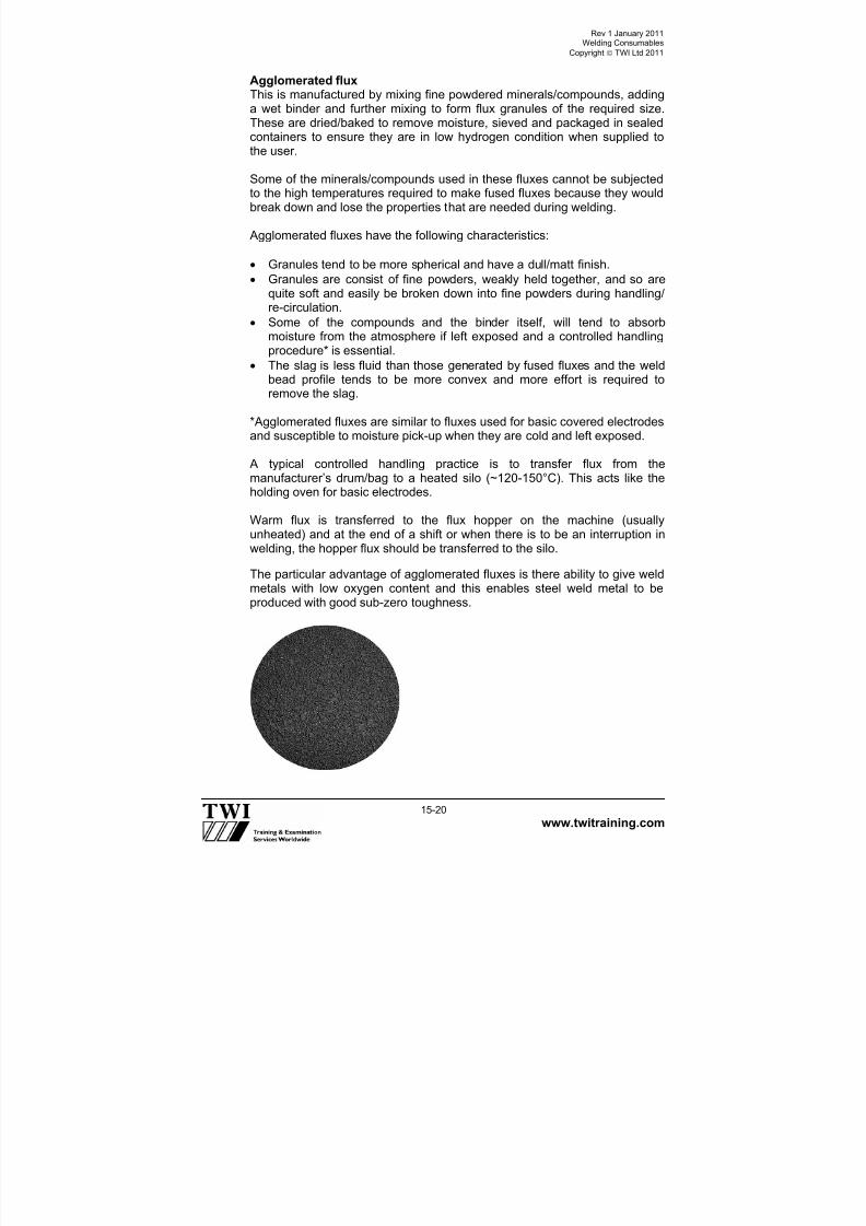
7/22/2019 CSWIP 3.2 LATEST WIS10-Mar-2011
http://slidepdf.com/reader/full/cswip-32-latest-wis10-mar-2011 194/303
Rev 1 January 2011Welding Consumables
Copyright TWI Ltd 2011
www.twitraining.com 15-20
Agglomerated fluxThis is manufactured by mixing fine powdered minerals/compounds, addinga wet binder and further mixing to form flux granules of the required size.These are dried/baked to remove moisture, sieved and packaged in sealedcontainers to ensure they are in low hydrogen condition when supplied to
the user.
Some of the minerals/compounds used in these fluxes cannot be subjectedto the high temperatures required to make fused fluxes because they wouldbreak down and lose the properties that are needed during welding.
Agglomerated fluxes have the following characteristics:
Granules tend to be more spherical and have a dull/matt finish.
Granules are consist of fine powders, weakly held together, and so arequite soft and easily be broken down into fine powders during handling/
re-circulation.
Some of the compounds and the binder itself, will tend to absorbmoisture from the atmosphere if left exposed and a controlled handlingprocedure* is essential.
The slag is less fluid than those generated by fused fluxes and the weldbead profile tends to be more convex and more effort is required toremove the slag.
*Agglomerated fluxes are similar to fluxes used for basic covered electrodesand susceptible to moisture pick-up when they are cold and left exposed.
A typical controlled handling practice is to transfer flux from themanufacturer’s drum/bag to a heated silo (~120-150°C). This acts like theholding oven for basic electrodes.
Warm flux is transferred to the flux hopper on the machine (usuallyunheated) and at the end of a shift or when there is to be an interruption inwelding, the hopper flux should be transferred to the silo.
The particular advantage of agglomerated fluxes is there ability to give weldmetals with low oxygen content and this enables steel weld metal to be
produced with good sub-zero toughness.

7/22/2019 CSWIP 3.2 LATEST WIS10-Mar-2011
http://slidepdf.com/reader/full/cswip-32-latest-wis10-mar-2011 195/303
Rev 1 January 2011Welding Consumables
Copyright TWI Ltd 2011
www.twitraining.com 15-21
15.8.2 SAW flux basicity index
Fluxes are often referred to as having a certain basicity or basicity index(BI).
The BI indicates the flux formulation according to the ratio of basiccompounds to acid compounds and is used to give an indication of flux/weldreaction and can be interpreted as follows:
A flux with a BI = 1 has an equal ratio of basic and acid compounds andthus is neither basic nor acid but said to be neutral.*
A flux with BI >1 has basic characteristics; fully basic fluxes have BI of~3-~3.5.
A flux with BI <1 has acid characteristics.
Fused and agglomerated fluxes are mixed to produce fluxes referred toas semi-basic.
* In the USA it is customary to use the terms neutral to indicate that the fluxhas no significant influence on the composition by transfer of elements fromflux to weld pool and active to indicate that the flux does transfer someelements
Fused fluxes have acid characteristics and agglomerated fluxes have basiccharacteristics.
Although there are EN and AWS standards for flux classification, it iscommon UK practice to order fluxes by manufacturer name and use this
name on WPSs.

7/22/2019 CSWIP 3.2 LATEST WIS10-Mar-2011
http://slidepdf.com/reader/full/cswip-32-latest-wis10-mar-2011 196/303
Section 16
MAG Welding
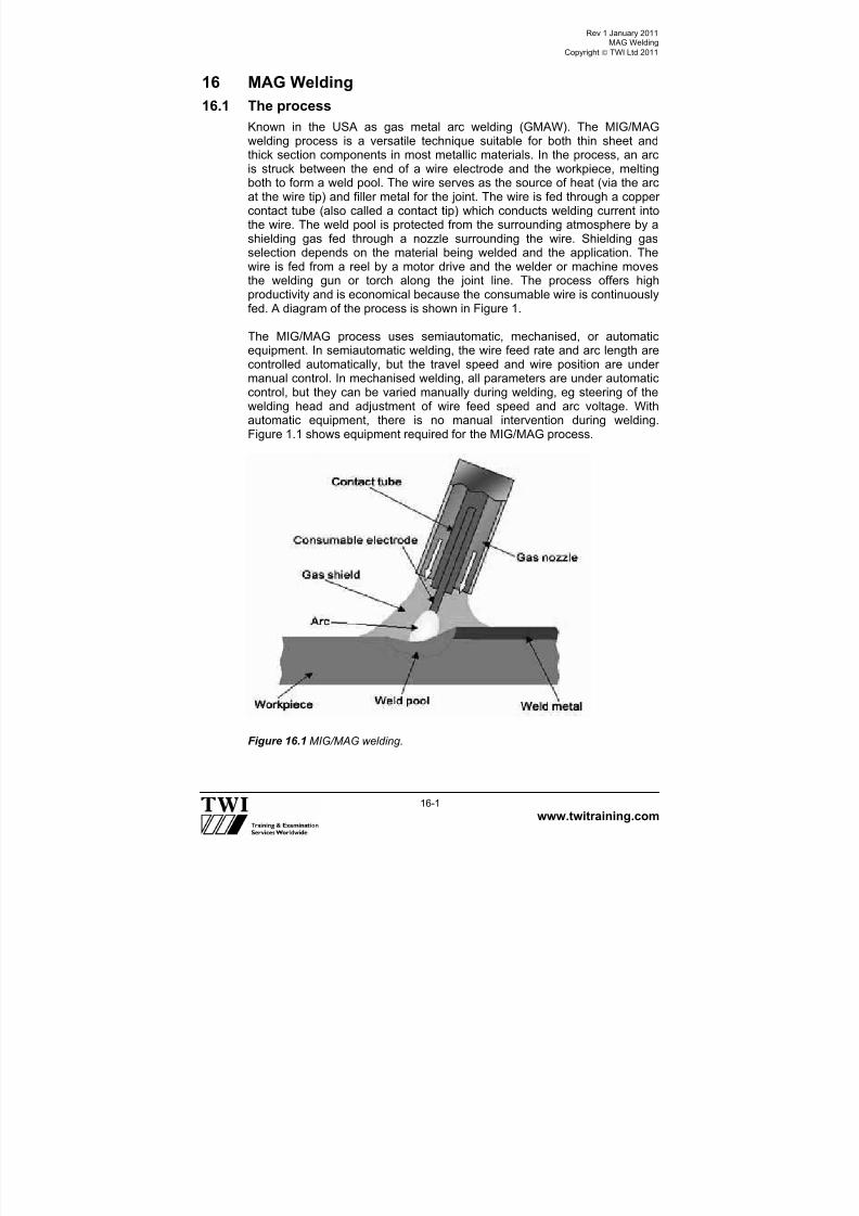
7/22/2019 CSWIP 3.2 LATEST WIS10-Mar-2011
http://slidepdf.com/reader/full/cswip-32-latest-wis10-mar-2011 197/303
Rev 1 January 2011MAG Welding
Copyright TWI Ltd 2011
www.twitraining.com 16-1
16 MAG Welding
16.1 The process
Known in the USA as gas metal arc welding (GMAW). The MIG/MAGwelding process is a versatile technique suitable for both thin sheet andthick section components in most metallic materials. In the process, an arcis struck between the end of a wire electrode and the workpiece, meltingboth to form a weld pool. The wire serves as the source of heat (via the arcat the wire tip) and filler metal for the joint. The wire is fed through a coppercontact tube (also called a contact tip) which conducts welding current intothe wire. The weld pool is protected from the surrounding atmosphere by ashielding gas fed through a nozzle surrounding the wire. Shielding gasselection depends on the material being welded and the application. Thewire is fed from a reel by a motor drive and the welder or machine movesthe welding gun or torch along the joint line. The process offers high
productivity and is economical because the consumable wire is continuouslyfed. A diagram of the process is shown in Figure 1.
The MIG/MAG process uses semiautomatic, mechanised, or automaticequipment. In semiautomatic welding, the wire feed rate and arc length arecontrolled automatically, but the travel speed and wire position are undermanual control. In mechanised welding, all parameters are under automaticcontrol, but they can be varied manually during welding, eg steering of thewelding head and adjustment of wire feed speed and arc voltage. Withautomatic equipment, there is no manual intervention during welding.Figure 1.1 shows equipment required for the MIG/MAG process.
Figure 16.1 MIG/MAG welding.
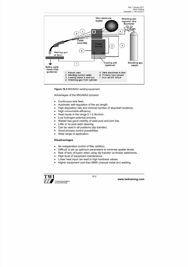
7/22/2019 CSWIP 3.2 LATEST WIS10-Mar-2011
http://slidepdf.com/reader/full/cswip-32-latest-wis10-mar-2011 198/303
Rev 1 January 2011MAG Welding
Copyright TWI Ltd 2011
www.twitraining.com 16-2
Figure 16.2 MIG/MAG welding equipment.
Advantages of the MIG/MAG process:
Continuous wire feed.
Automatic self-regulation of the arc length.
High deposition rate and minimal number of stop/start locations.
High consumable efficiency.
Heat inputs in the range 0.1-2.0kJ/mm.
Low hydrogen potential process
Welder has good visibility of weld pool and joint line.
Little or no post weld cleaning.
Can be used in all positions (dip transfer).
Good process control possibilities. Wide range of application.
Disadvantages
No independent control of filler addition.
Difficult to set up optimum parameters to minimise spatter levels.
Risk of lack of fusion when using dip transfer on thicker weldments.
High level of equipment maintenance.
Lower heat input can lead to high hardness values.
Higher equipment cost than MMA (manual metal arc) welding.

7/22/2019 CSWIP 3.2 LATEST WIS10-Mar-2011
http://slidepdf.com/reader/full/cswip-32-latest-wis10-mar-2011 199/303
Rev 1 January 2011MAG Welding
Copyright TWI Ltd 2011
www.twitraining.com 16-3
Site welding requires special precautions to exclude draughts which maydisturb the gas shield.
Joint and part access is not as good as MMA or TIG welding.
Cleanliness of base metal slag processes can tolerate greatercontamination.
16.2 Process variables
The primary variables in MIG/MAG welding are:
Welding current/wire feed speed.
Voltage.
Gases.
Travel speed and electrode orientation.
Inductance.
Contact tip to work distance.
Nozzle to work distance.
Shielding gas nozzle.
Type of metal transfer.
16.2.1 Welding current / wire feed speed
On MIG/MAG welding sets there is no control to set the welding current. Theelectrical characteristics of the welding set (flat or constant voltage type)automatically alters the welding current with changes to the set wire feedspeed to achieve a constant arc length.
Increasing the wire feed, and therefore current, increases wire burn-off,deposition rate and penetration.
Current type is almost always DC+ve, although some cored wires requireDC-ve for best results.
16.2.2 Voltage
This is set to achieve steady smooth welding conditions and is generallyincreased as the wire feed speed is increased.
Increase in voltage increases the width of the weld and reduces penetration.
16.2.3 Travel speed and electrode orientation
The faster the travel speed the less penetration, narrower bead width andthe higher risk of undercut

7/22/2019 CSWIP 3.2 LATEST WIS10-Mar-2011
http://slidepdf.com/reader/full/cswip-32-latest-wis10-mar-2011 200/303
Rev 1 January 2011MAG Welding
Copyright TWI Ltd 2011
www.twitraining.com 16-4
Figure 16.3 The effect of travel speed.
Figure 16.4 The effect of torch angle.
16.2.4 Effect of contact tip to workpiece distance (CTWD)
The CTWD has an influence over the welding current because of resistiveheating in the electrode extension (see Figure 4). The welding currentrequired to melt the electrode at the required rate (to match the wire feedspeed) reduces as the CTWD is increased. Long electrode extensions cancause lack of penetration, for example, in narrow gap joints, or with poormanipulation of the welding gun. Conversely, the welding current increases
when the CTWD is reduced.
• Increasing travel speed
• Reduced penetration and width,undercut
Penetration Deep Moderate ShallowExcess weld metal Maximum Moderate MinimumUndercut Severe Moderate Minimum

7/22/2019 CSWIP 3.2 LATEST WIS10-Mar-2011
http://slidepdf.com/reader/full/cswip-32-latest-wis10-mar-2011 201/303
Rev 1 January 2011MAG Welding
Copyright TWI Ltd 2011
www.twitraining.com 16-5
Figure 16.5 Contact tip to workpiece distance; electrode extension and nozzle toworkpiece distance.
Figure 16.6 The effect of increasing electrode extension.
The electrode extension should be checked when setting-up weldingconditions or when fitting a new contact tube. Normally measured from thecontact tube to the work piece (Figure 5) suggested CTWDs for the principalmetal transfer modes are:
Metal transfer mode CTWD, mm Dip 10-15
Spray 20-25
Pulse 15-20
Workpiece
Gas nozzle
Contact
Electrodeextension
Contact tip-to-work distance Arc len th
Contact tipsetback
Nozzle-to-work (stand-off) distance
Increased extension

7/22/2019 CSWIP 3.2 LATEST WIS10-Mar-2011
http://slidepdf.com/reader/full/cswip-32-latest-wis10-mar-2011 202/303
Rev 1 January 2011MAG Welding
Copyright TWI Ltd 2011
www.twitraining.com 16-6
16.2.5 Effect of nozzle to work distance
Nozzle to work distance (see Figure 4) has a considerable effect on gasshielding efficiency; a decrease having the effect of stiffening the column.The nozzle to work distance is typically 12-15mm. If the CTWD issimultaneously reduced, however, the deposition rate at a given current isdecreased and visibility and accessibility are affected; so, in practice, acompromise is necessary. The following gives suggested settings for themode of metal transfer being used
Metal transfer mode Contact tip position relative to nozzleDip 2mm inside to 2mm protruding
Spray 4-8mm inside
Spray (aluminium) 6-10mm inside
16.2.6 Shielding gas nozzle
The purpose of the shielding gas nozzle is to produce a laminar gas flow inorder to protect the weld pool from atmospheric contamination. Nozzle sizesrange from 13-22mm diameter. The nozzle diameter should be increased inrelation to the size of the weld pool.
16.2.7 Types of metal transfer
Figure 16.7 Arc characteristic curve.

7/22/2019 CSWIP 3.2 LATEST WIS10-Mar-2011
http://slidepdf.com/reader/full/cswip-32-latest-wis10-mar-2011 203/303
Rev 1 January 2011MAG Welding
Copyright TWI Ltd 2011
www.twitraining.com 16-7
1) Dip transfer:
Key characteristics:
Metal transfer by wire dipping or short circuiting into the weld pool.
Relatively low heat input process.
Low weld pool fluidity. Used for thin sheet metal above 0.8 and typically less than 3.2mm,
positional welding of thicker section and root runs in open butt joints.
Process stability and spatter can be a problem if poorly tuned.
Lack of fusion risk if poorly set up and applied.
Not used for non-ferrous metals and alloys.
In dip transfer the wire short-circuits the arc between 50–200 times/sec. Thistype of transfer is normally achieved with CO2 or mixtures of CO2 and argongas + low amps and welding volts < 24V.
Figure 16.8 Dip transfer.
2) Spray transfer:
Key characteristics:
Free-flight metal transfer.
High heat input.
High deposition rate.
Smooth, stable arc.
Used on steels above 6mm thickness and aluminium alloys above 3mmthickness.
Spray transfer occurs at high currents and high voltages. Above thetransition current, metal transfer is in the form of a fine spray of small
droplets, which are projected across the arc with low spatter levels. The highwelding current produces strong electromagnetic forces (known as the pincheffect' that cause the molten filament supporting the droplet to neck down.The droplets detach from the tip of the wire and accelerate across the arcgap.
With steels it can be used only in down-hand butts and H/V fillet welds, butgives significantly higher deposition rate, penetration and fusion than the diptransfer mode. With aluminum alloys it can be used in all positions.

7/22/2019 CSWIP 3.2 LATEST WIS10-Mar-2011
http://slidepdf.com/reader/full/cswip-32-latest-wis10-mar-2011 204/303
Rev 1 January 2011MAG Welding
Copyright TWI Ltd 2011
www.twitraining.com 16-8
Figure 16.9 Spray transfer .
3) Pulsed transfer:
Key characteristics:
Free-flight droplet transfer without short-circuiting over the entire workingrange.
Very low spatter.
Lower heat input than spray transfer.
Reduced risk of lack of fusion compared with dip transfer.
Control of weld bead profile for dynamically loaded parts.
Process control/flexibility.
Enables use of larger diameter, less expensive wires with thinner plates – more.
Easily fed (a particular advantage for aluminium welding).
Pulsing the welding current extends the range of spray transfer operationwell below the natural transition from dip to spray transfer. This allowssmooth, spatter-free spray transfer to be obtained at mean currents belowthe transition level, eg 50-150A and at lower heat inputs.
A typical pulse waveform and the main pulse welding variables are shown inFigure 16.10. Pulse transfer uses pulses of current to fire a single globule ofmetal across the arc gap at a frequency between 50–300 pulses/sec. Pulsetransfer is a development of spray transfer that gives positional weldingcapability for steels, combined with controlled heat input, good fusion, andhigh productivity. It may be used for all sheet steel thickness >1mm, but ismainly used for positional welding of steels >6mm.

7/22/2019 CSWIP 3.2 LATEST WIS10-Mar-2011
http://slidepdf.com/reader/full/cswip-32-latest-wis10-mar-2011 205/303
Rev 1 January 2011MAG Welding
Copyright TWI Ltd 2011
www.twitraining.com 16-9
Figure 16.10 Pulsed welding waveform and parameters.
4) Globular transfer:
Key characteristics:
Irregular metal transfer.
Medium heat input.
Medium deposition rate.
Risk of spatter.
Not widely used in the UK; can be used for mechanised welding ofmedium.
Thickness steels (typically 3-6mm) in the flat (PA) position.
The globular transfer range occupies the transitional range of arc voltagebetween free flight and fully short-circuiting transfer. Irregular droplettransfer and arc instability are inherent, particularly when operating near thetransition threshold. In globular transfer, a molten droplet of several timesthe electrode diameter forms on the wire tip. Gravity eventually detaches theglobule when its weight overcomes surface tension forces and transfertakes place often with excessive spatter
To minimise spatter levels, it is common to operate with a very short arclength and in some cases a buried arc technique is adopted. Globulartransfer can only be used in the flat position and is often associated withlack of penetration, fusion defects and uneven weld beads, because of theirregular transfer and tendency for arc wander.
16.2.8 Inductance
What does inductance do?When MIG welding in the dip transfer mode, the welding electrode touchesthe weld pool, causing a short circuit. During the short circuit, the arc voltageis nearly zero. If the constant voltage power supply responded instantly,
very high current would immediately begin to flow through the welding

7/22/2019 CSWIP 3.2 LATEST WIS10-Mar-2011
http://slidepdf.com/reader/full/cswip-32-latest-wis10-mar-2011 206/303
Rev 1 January 2011MAG Welding
Copyright TWI Ltd 2011
www.twitraining.com 16-10
circuit. The rapid rise in current to a high value would melt the short-circuitedelectrode free with explosive force, dispelling the weld metal and causingconsiderable spatter.
Inductance is the property in an electrical circuit that slows down the rate of
current rise (Figure 16.11). The current travelling through an inductance coilcreates a magnetic field. This magnetic field creates a current in the weldingcircuit that is in opposition to the welding current. Increasing the inductancewill also increase the arc time and decrease the frequency of short-circuiting.
For each electrode feed rate, there is an optimum value of inductance. Toolittle inductance results in excessive spatter. If too much inductance is used,the current will not rise fast enough and the molten tip of the electrode is notheated sufficiently causing the electrode to stub into the base metal. Modernelectronic power sources automatically set the inductance to give a smooth
arc and metal transfer.
Figure 16.11 Relationship between inductance and current rise.
16.3 Welding consumables
16.3.1 Solid wires
Usually made in sizes from 0.6 to 1,6mm diameter they are produced withan analysis which essentially matches the materials being joined. Additionalelements are often added especially extra de-oxidants in steel wires. C-Mnand low alloy steel wires are usually copper coated to reduce the risk ofrusting and promote better electrical contact.
16.3.2 Flux cored wires
A cored wire consists of a metal sheath containing a granular flux. This fluxcan contain elements that would normally be used in MMA electrodes and
so the process has a very wide range of applications.

7/22/2019 CSWIP 3.2 LATEST WIS10-Mar-2011
http://slidepdf.com/reader/full/cswip-32-latest-wis10-mar-2011 207/303
Rev 1 January 2011MAG Welding
Copyright TWI Ltd 2011
www.twitraining.com 16-11
In addition we can also add gas producing elements and compounds to theflux and so the process can become independent of a separate gas shield,which restricted the use of conventional MIG/MAG welding in many fieldapplications.
Most wires are sealed mechanically and hermetically with various forms of joint. The effectiveness of the joint of the wire is an inspection point of coredwire welding as moisture can easily be absorbed into a damaged or poorseam.
Wire types commonly used are:
Rutile – which give good positional capabilities..
Basic – also positional but good on “dirty” material.
Metal cored – higher productivity and some having excellent root runcapabilities.
Self-shielded – no external gas needed.
Baking of cored wires is ineffective and will do nothing to restore thecondition of a contaminated flux within a wire.
Note that unlike MMA electrodes the potential hydrogen levels andmechanical properties of welds with rutile wires can equal those of the basictypes.
16.4 Important inspection points/checks when MIG/MAG welding
1 The welding equipment A visual check should be made to ensure the welding equipment is ingood condition.
2 The eectrode wireThe diameter, specification and the quality of the wire are the maininspection headings. The level of de-oxidation of the wire is an importantfactor with single, double and triple de-oxidised wires being available.
The higher the level of de-oxidants in the wire, then the lower the chanceof porosity in the weld. The quality of the wire winding, copper coating,and temper are also important factors in minimising wire feed problems.
Quality of wire windings and increasing costs
(a) Random wound. (b) Layer wound. (c) Precision layer wound.
3 The drive rolls and liner.Check the drive rolls are of the correct size for the wire and that thepressure is only hand tight, or just sufficient to drive the wire. Any excesspressure will deform the wire to an ovular shape. This will make the wire

7/22/2019 CSWIP 3.2 LATEST WIS10-Mar-2011
http://slidepdf.com/reader/full/cswip-32-latest-wis10-mar-2011 208/303
Rev 1 January 2011MAG Welding
Copyright TWI Ltd 2011
www.twitraining.com 16-12
very difficult to drive through the liner and result in arcing in the contacttip and excessive wear of the contact tip and liner.
Check that the liner is the correct type and size for the wire. A size ofliner will generally fit 2 sizes of wire ie (0.6 and 0.8) (1.0 and 1.2) (1.4
and 1.6) mm diameter. Steel liners are used for steel wires and Teflonliners for aluminium wires.
4 The contact tipCheck that the contact tip is the correct size for the wire being driven,and check the amount of wear frequently. Any loss of contact betweenthe wire and contact tip will reduce the efficiency of current pick. Moststeel wires are copper-coated to maximise the transfer of current bycontact between 2 copper surfaces at the contact tip, this also inhibitscorrosion. The contact tip should be replaced regularly.
5 The connectionsThe length of the electric arc in MIG/MAG welding is controlled by thevoltage settings. This is achieved by using a constant voltage volt/ampcharacteristic inside the equipment. Any poor connection in the weldingcircuit will affect the nature and stability of the electric arc, and is thus isa major inspection point.
6 Gas and gas flow rateThe type of gas used is extremely important to MIG/MAG welding, as isthe flow rate from the cylinder, which must be adequate to give goodcoverage over the solidifying and molten metal to avoid oxidation andporosity.
7 Other variable welding parametersChecks should be made for correct wire feed speed, voltage, speed oftravel, and all other essential variables of the process given on theapproved welding procedure.
8 Safety checksChecks should be made on the current carrying capacity, or duty cycle ofequipment and electrical insulation. Correct extraction systems should
be in use to avoid exposure to ozone and fumes.

7/22/2019 CSWIP 3.2 LATEST WIS10-Mar-2011
http://slidepdf.com/reader/full/cswip-32-latest-wis10-mar-2011 209/303
Rev 1 January 2011MAG Welding
Copyright TWI Ltd 2011
www.twitraining.com 16-13
A check should always be made to ensure that the welder is qualified toweld the procedure being employed.
Typical welding imperfections:
1 Silica inclusions, (on ferritic steels only) caused by poor inter-runcleaning.
2 Lack of sidewall fusion during dip transfer welding thick sectionvertically down.
3 Porosity caused from loss of gas shield and low tolerance tocontaminants
4 Burn-through from using the incorrect metal transfer mode on sheetmetal

7/22/2019 CSWIP 3.2 LATEST WIS10-Mar-2011
http://slidepdf.com/reader/full/cswip-32-latest-wis10-mar-2011 210/303
Section 17
MMA Welding

7/22/2019 CSWIP 3.2 LATEST WIS10-Mar-2011
http://slidepdf.com/reader/full/cswip-32-latest-wis10-mar-2011 211/303
Rev 1 January 2011MMA Welding
Copyright TWI Ltd 2011
www.twitraining.com
17-1
17 MMA Welding
17.1 Manual metal-arc/shielded metal arc welding (MMA/SMAW)
The most versatile of the welding processes, manual metal arc (MMA)welding is suitable for welding most ferrous and non-ferrous metals, over awide range of thicknesses. The MMA welding process can be used in allpositions, with reasonable ease of use and relatively economically. The finalweld quality is primarily dependent on the skill of the welder.
When an arc is struck between the coated electrode and the workpiece,both the electrode and workpiece surface melt to form a weld pool. Theaverage temperature of the arc is approximately 6000°C, which is sufficientto simultaneously melt the parent metal, consumable core wire and the fluxcoating. The flux forms gas and slag, which protects the weld pool fromoxygen and nitrogen in the surrounding atmosphere. The molten slag
solidifies and cools and must be chipped off the weld bead once the weldrun is complete (or before the next weld pass is deposited). The processallows only short lengths of weld to be produced before a new electrodeneeds to be inserted in the holder.
The manual metal arc welding process.

7/22/2019 CSWIP 3.2 LATEST WIS10-Mar-2011
http://slidepdf.com/reader/full/cswip-32-latest-wis10-mar-2011 212/303
Rev 1 January 2011MMA Welding
Copyright TWI Ltd 2011
www.twitraining.com
17-2
17.2 MMA welding basic equipment requirements
1 Power source transformer/rectifier (constant current type). 2 Holding oven (holds at temperatures up to 150°C). 3 Inverter power source (more compact and portable). 4 Electrode holder (of a suitable amperage rating). 5 Power cable (of a suitable amperage rating). 6 Welding visor (with correct rating for the amperage/process). 7 Power return cable (of a suitable amperage rating).
8 Electrodes (of a suitable type and amperage rating). 9 Electrode oven (bakes electrodes at up to 350°C). 10 Control panel (on\off/amperage/polarity/OCV).
17.3 Power requirements
Manual metal arc welding can be carried out using either direct (DC) oralternating (AC) current. With DC welding current either positive (+ve) ornegative (-ve) polarity can be used, so current is flowing in one direction. ACwelding current flows from negative to positive and is two directional.
1
2
10
5
4
38
9
7

7/22/2019 CSWIP 3.2 LATEST WIS10-Mar-2011
http://slidepdf.com/reader/full/cswip-32-latest-wis10-mar-2011 213/303
Rev 1 January 2011MMA Welding
Copyright TWI Ltd 2011
www.twitraining.com
17-3
Power sources for MMA welding are transformers (which transforms mains AC to AC suitable for welding), transformer-rectifiers (which rectifies AC toDC), diesel or petrol driven generators (preferred for site work) or inverters(a more recent addition to welding power sources). For MMA welding apower source with a constant current (drooping) output characteristic must
be used.
The power source must provide:
An open circuit voltage (OCV) to initiate the arc, between 50 and 90V.
Welding voltage to maintain the arc during welding, between 20 and30V.
A suitable current range, typically 30-350A.
A stable arc. Rapid arc recovery or arc re-ignition without current surge.
A constant welding current. The arc length may change during welding,but consistent electrode burn-off rate and weld penetrationcharacteristics must be maintained during welding.
17.4 Welding variables
Other factors, or welding variables, which affect the final quality of the MMAweld, are:
Current (amperage)Voltage affects heat InputTravel speed
PolarityType of electrode
17.4.1 Current (amperage)
Amperage controls burn-off rate and depth of penetration. Welding currentlevel is determined by the size of electrode and the welding position -manufacturers recommend the normal operating range and current.
Incorrect amperage settings when using MMA can contribute to thefollowing:
Amperage too lowPoor fusion or penetration, irregular weld bead shape, slag inclusionunstable arc, porosity, potential arc strikes, difficult starting.
Amperage too highExcessive penetration, burn-through, undercut, spatter, porosity, deepcraters, electrode damage due to overheating, high deposition makingpositional welding difficult.

7/22/2019 CSWIP 3.2 LATEST WIS10-Mar-2011
http://slidepdf.com/reader/full/cswip-32-latest-wis10-mar-2011 214/303
Rev 1 January 2011MMA Welding
Copyright TWI Ltd 2011
www.twitraining.com
17-4
17.5 Voltage
Open circuit voltage (OCV) is the voltage measured between the outputterminals of the power source when no current is flowing through thewelding circuit.
For safety reasons this should not exceed 100V and is usually between50-90V.
Arc voltage is the voltage required to maintain the arc during welding and isusually between 20–30V. As arc voltage is a function of arc length thewelder controls the arc length and therefore the arc voltage.
Arc voltage controls weld pool fluidity.
The effects of having the wrong arc voltage can be:
Arc Voltage too lowPoor penetration, electrode stubbing, lack of fusion defects, potential for arcstrikes, slag inclusion, unstable arc condition, irregular weld bead shape.
Arc voltage too highExcessive spatter, porosity, arc wander, irregular weld bead shape, slaginclusions, fluid weld pool making positional welding difficult.
17.5.1 Travel speed
Travel speed is related to whether the welding is progressed by stringerbeads or by weaving. Often the run out length (ROL) ie the length of depositfrom one standard electrode is quoted on procedures rather than speed as itis easier for the welder to visualise.
Travel speed too fastNarrow thin weld bead, fast cooling, slag inclusions, undercut, poorfusion/penetration.
Travel speed too slowCold lap, excess weld deposition, irregular bead shape, undercut.

7/22/2019 CSWIP 3.2 LATEST WIS10-Mar-2011
http://slidepdf.com/reader/full/cswip-32-latest-wis10-mar-2011 215/303
Rev 1 January 2011MMA Welding
Copyright TWI Ltd 2011
www.twitraining.com
17-5
17.6 Type of current and polarity
Polarity will determine the distribution of heat energy at the welding arc. Thepreferred polarity of the MMA system depends primarily upon the electrodebeing used and the desired properties of the weld.
Direct current. electrode positive (DCEP / DC+).Usually produces the greatest penetration but with lesser deposition rate.Known in some standards as reverse polarity.
Direct current. electrode negative (DCEN / DC-)Usually produces less penetration with greater deposition rate.Known in some standards as straight polarity.
When using direct current the arc can be affected by arc blow . Thedeflection of the arc from its normal path due to magnetic forces.
Alternating current (AC)The distribution of heat energy at the arc is equal.
Operating factor (O/F)The percentage (%) of arc on time in a given time span.
When compared with semi automatic welding processes the MMA weldingprocess has a low O/F of approximately 30% Manual semi-automaticMIG/MAG O/F is in the region 60% with fully automated MIG/MAG in theregion of 90% O/F. A welding process O/F can be directly linked to
productivity.
Operating Factor should not to be confused with the term duty cycle,which is a safety value given as the % of time a conductor can carry acurrent and is given as a specific current at 60 and 100% of 10 minutes ie350A 60% and 300A 100%.
17.7 Type of consumable electrode
For MMA welding there are three generic types of flux covering:
Rutile, basic, cellulosicThe details of these types are covered elsewhere in these notes.
17.8 Typical welding defects
1 Slag inclusions caused by poor welding technique or insufficient inter-run cleaning.
2 Porosity from using damp or damaged electrodes or when weldingcontaminated or unclean material.

7/22/2019 CSWIP 3.2 LATEST WIS10-Mar-2011
http://slidepdf.com/reader/full/cswip-32-latest-wis10-mar-2011 216/303
Rev 1 January 2011MMA Welding
Copyright TWI Ltd 2011
www.twitraining.com
17-6
3 Lack of root fusion or penetration caused by in-correct settings of theamps, root gap or face width.
4 Undercut caused by too high amperage for the position or by a poorwelding technique eg travel speed too fast or too slow, arc length
(therefore voltage) variations particularly during excessive weaving.
5 Arc strikes caused by incorrect arc striking procedure, or lack of skill.These may be also caused by incorrectly fitted/secured power returnlead clamps.
6 Hydrogen cracks caused by the use of incorrect electrode type orincorrect baking procedure and/or control of basic coated electrodes.

7/22/2019 CSWIP 3.2 LATEST WIS10-Mar-2011
http://slidepdf.com/reader/full/cswip-32-latest-wis10-mar-2011 217/303
Section 18
Submerged Arc

7/22/2019 CSWIP 3.2 LATEST WIS10-Mar-2011
http://slidepdf.com/reader/full/cswip-32-latest-wis10-mar-2011 218/303
Rev 1 January 2011Submerged Arc
Copyright TWI Ltd 2011
www.twitraining.com 18-1
18 Submerged Arc
18.1 The process
Abbreviated as SAW, this is a welding process where an arc is struckbetween a continuous bare wire and the parent plate. The arc, electrodeend and the molten pool are submerged in an agglomerated or fusedpowdered flux, which turns, into a gas and slag in its lower layers whensubjected to the heat of the arc, thus protecting the weld fromcontamination. The wire electrode is fed continuously by a feed unit ofmotor-driven rollers, which usually are voltage-controlled to ensure an arc ofconstant length. The flux is fed from a hopper fixed to the welding head, anda tube from the hopper spreads the flux in a continuous elongated mound infront of the arc along the line of the intended weld and of sufficient depth tosubmerge the arc completely so that there is no spatter, the weld is shieldedfrom the atmosphere and there are no ultraviolet or infra-red radiation
effects (see below). Unmelted flux is reclaimed for use. The use ofpowdered flux restricts the process to the flat and horizontal-vertical weldingpositions.
Submerged arc welding is noted for its ability to employ high weld currentsowing to the properties and functions of the flux. Such currents give deeppenetration and high deposition rates. Generally a DC electrode positivepolarity is employed up to about 1000A because it produces a deeppenetration. On some applications (ie cladding operations) DC electrodenegative is needed to reduce penetration and dilution. At higher currents orin case of multiple electrode systems, AC is often preferred to avoid theproblem of arc blow (when used with multiple electrode systems, DC
electrode positive is used for the lead arc and AC is used for the trail arc).

7/22/2019 CSWIP 3.2 LATEST WIS10-Mar-2011
http://slidepdf.com/reader/full/cswip-32-latest-wis10-mar-2011 219/303
Rev 1 January 2011Submerged Arc
Copyright TWI Ltd 2011
www.twitraining.com 18-2
Power sources can be of the constant current or constant voltage type eithermay have outputs exceeding 1000A.
Difficulties sometimes arise in ensuring conformity of the weld with apredetermined line owing to the obscuring effect of the flux. Where possible,a guide wheel to run in the joint preparation is positioned in front of thewelding head and flux hoppers.
Submerged arc welding is widely used in the fabrication of ships, pressure
vessels, linepipe, railway carriages and anywhere where long welds arerequired. It can be used to weld thicknesses from 1.5mm upwards.
Materials joined
Welding of carbon steels.
Welding low alloy steels (eg fine grained and creep resisting).
Welding stainless steels.
Welding nickel alloys.
Cladding to base metals to improve wear and corrosion resistance.
18.2 Process variables
There are several variables which when changed can have an effect on theweld appearance and mechanical properties:
Welding current.
Type of flux and particle distribution.
Arc voltage.
Travel speed.
Electrode size.
Electrode extension.
Type of electrode.
Width and depth of the layer of flux.
Electrode angle, (leading, trailing).
Polarity.
Single-, double- or multi-wire system.
18.2.1 Welding current
Welding current effect on weld profile (2.4mm electrode diameter, 35V arcvoltage and 61cm/min travel speed)

7/22/2019 CSWIP 3.2 LATEST WIS10-Mar-2011
http://slidepdf.com/reader/full/cswip-32-latest-wis10-mar-2011 220/303
Rev 1 January 2011Submerged Arc
Copyright TWI Ltd 2011
www.twitraining.com 18-3
Excessively high current produces a deep penetrating arc with atendency to burn-through, undercut or a high, narrow bead prone tosolidification cracking.
Excessively low current produces an unstable arc, lack of penetrationand possibly lack of fusion.
18.2.2 Arc voltage
Arc voltage adjustment varies the length of the arc between the electrodeand the molten weld metal. If the arc voltage increases, the arc lengthincreases and vice versa. The voltage principally determines the shape ofthe weld bead cross section and its external appearance.
25V 35V 45V
Arc voltage effect on weld profile (2.4mm electrode diameter, 500A weldingcurrent and 61cm/min travel speed)
Increasing the arc voltage will:
Produce a flatter and wider bead.
Increase flux consumption.
Tend to reduce porosity caused by rust or scale on steel.
Help to bridge excessive root opening when fit-up is poor.
Increase pick-up of alloying elements from the flux when they are
present.
Excessively high arc voltage will:
Produce a wide bead shape that is subject to solidification cracking.
Make slag removal difficult in groove welds.
Produce a concave shaped fillet weld that may be subject to cracking.
Increase undercut along the edge(s) of fillet welds.
Over-alloy the weld metal, via the flux.
350A 500A 650A
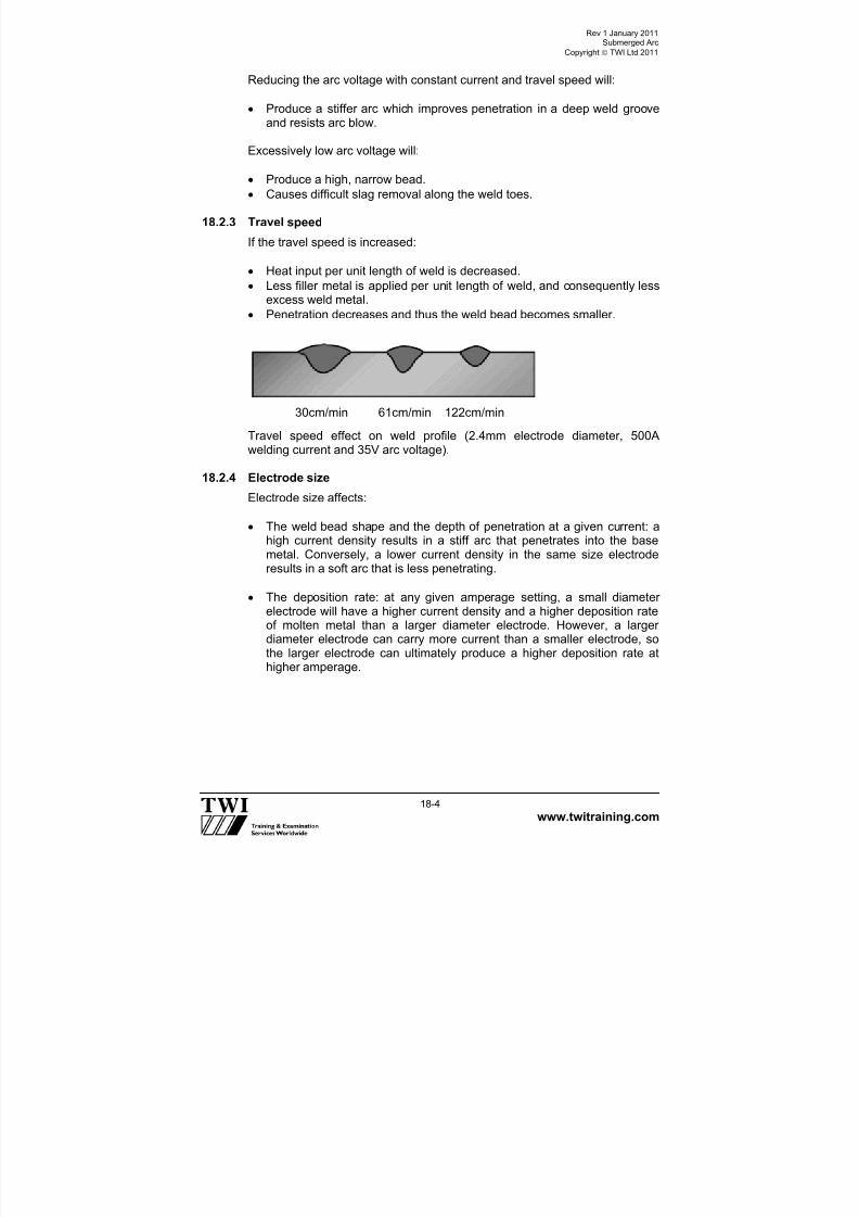
7/22/2019 CSWIP 3.2 LATEST WIS10-Mar-2011
http://slidepdf.com/reader/full/cswip-32-latest-wis10-mar-2011 221/303
Rev 1 January 2011Submerged Arc
Copyright TWI Ltd 2011
www.twitraining.com 18-4
Reducing the arc voltage with constant current and travel speed will:
Produce a stiffer arc which improves penetration in a deep weld grooveand resists arc blow.
Excessively low arc voltage will:
Produce a high, narrow bead.
Causes difficult slag removal along the weld toes.
18.2.3 Travel speed
If the travel speed is increased:
Heat input per unit length of weld is decreased.
Less filler metal is applied per unit length of weld, and consequently less
excess weld metal. Penetration decreases and thus the weld bead becomes smaller.
30cm/min 61cm/min 122cm/min
Travel speed effect on weld profile (2.4mm electrode diameter, 500A
welding current and 35V arc voltage).
18.2.4 Electrode size
Electrode size affects:
The weld bead shape and the depth of penetration at a given current: ahigh current density results in a stiff arc that penetrates into the basemetal. Conversely, a lower current density in the same size electroderesults in a soft arc that is less penetrating.
The deposition rate: at any given amperage setting, a small diameterelectrode will have a higher current density and a higher deposition rate
of molten metal than a larger diameter electrode. However, a largerdiameter electrode can carry more current than a smaller electrode, sothe larger electrode can ultimately produce a higher deposition rate athigher amperage.

7/22/2019 CSWIP 3.2 LATEST WIS10-Mar-2011
http://slidepdf.com/reader/full/cswip-32-latest-wis10-mar-2011 222/303
Rev 1 January 2011Submerged Arc
Copyright TWI Ltd 2011
www.twitraining.com 18-5
Electrode size effect on weld profile (600A welding current, 30V arc voltageand 76cm/min travel speed).
18.2.5 Electrode extension
The electrode extension is the distance the continuous electrode protrudesbeyond the contact tip. At high current densities, resistance heating of theelectrode between the contact tip and the arc can be utilised to increase the
electrode melting rate (as much as 25-50%). The longer the extension, thegreater the amount of heating and the higher the melting rate (see below).
18.2.6 Type of electrode An electrode with a low electrical conductivity, such as stainless steel, canwith a normal electrode extension experience greater resistance heating.Thus for the same size electrode and current, the melting rate of a stainlesssteel electrode will be higher than that of a carbon steel electrode.
18.2.7 Width and depth of flux
The width and depth of the layer of granular flux influence the appearanceand soundness of the finished weld as well as the welding action. If thegranular layer is too deep, the arc is too confined and a rough weld with a
rope-like appearance is likely to result, it may also produce local flat areason the surface often referred to as gas flats. The gases generated duringwelding cannot readily escape, and the surface of the molten weld metal isirregularly distorted. If the granular layer is too shallow, the arc will not beentirely submerged in flux. Flashing and spattering will occur. The weld willhave a poor appearance, and it may show porosity.
3.2 mm 4.0 mm 5.0 mm
30mm 45mm 60mm 80mm

7/22/2019 CSWIP 3.2 LATEST WIS10-Mar-2011
http://slidepdf.com/reader/full/cswip-32-latest-wis10-mar-2011 223/303
Rev 1 January 2011Submerged Arc
Copyright TWI Ltd 2011
www.twitraining.com 18-6
18.3 Storage and care of consumables
Care must be given to fluxes supplied for SAW which, although they may bedry when packaged, may be exposed to high humidity during storage. Insuch cases they should be stored in accordance with the manufacturer's
recommendations before use, or porosity or cracking may result. It rarelypractical or economical to re-dry fluxes which may have picked up moisture.
Ferrous wire coils supplied as continuous feeding electrodes are usuallycopper-coated. This provides some corrosion resistance, ensures goodelectrical contacts and helps in smooth feeding. Rust and mechanicaldamage should be avoided in such products, as they will both interruptsmooth feeding of the electrode. Rust will be detrimental to weld qualitygenerally since rust is a hygroscopic material (may contain or absorbmoisture) and thus it can lead to hydrogen induced cracking.
Contamination by carbon containing materials such as oil, grease, paint anddrawing lubricants is especially harmful with ferrous metals. Carbon pick-upin the weld metal can cause a marked and usually undesirable change inproperties. Such contaminants may also result in hydrogen being absorbedin the weld pool.
Welders should always follow the manufacturer's recommendations forconsumables storage and handling

7/22/2019 CSWIP 3.2 LATEST WIS10-Mar-2011
http://slidepdf.com/reader/full/cswip-32-latest-wis10-mar-2011 224/303
Section 19
TIG Welding

7/22/2019 CSWIP 3.2 LATEST WIS10-Mar-2011
http://slidepdf.com/reader/full/cswip-32-latest-wis10-mar-2011 225/303
Rev 1 January 2011TIG Welding
Copyright TWI Ltd 2011
www.twitraining.com 19-1
19 TIG Welding
19.1 Process characteristics
In the USA the TIG process is also called gas tungsten arc welding (GTAW).TIG welding is a process where melting is produced by heating with an arcstruck between a non-consumable tungsten electrode and the workpiece.
An inert gas is used to shield the electrode and weld zone to preventoxidation of the tungsten electrode and atmospheric contamination of theweld and hot filler wire (as shown below).
Manual TIG welding.
Tungsten is used because it has a melting point of 3370°C, which is well
above any other common metal.
The power source is of the constant current type.

7/22/2019 CSWIP 3.2 LATEST WIS10-Mar-2011
http://slidepdf.com/reader/full/cswip-32-latest-wis10-mar-2011 226/303
Rev 1 January 2011TIG Welding
Copyright TWI Ltd 2011
www.twitraining.com 19-2
19.2 Process variables
The main variables in TIG welding are:
Welding current.
Current type and polarity. Travel speed.
Shape of tungsten electrode tip and vertex angle.
Shielding gas flow rate.
Each of these variables is considered in more detail in the following sub-sections.
19.2.1 Welding current
Weld penetration is directly related to welding current.
If the welding current is too low, the electrode tip will not be properlyheated and an unstable arc may result.
If the welding current is set too high, the electrode tip might overheat andmelt, leading to tungsten inclusions.
19.2.2 Current type and polarity
With steels DC electrode negative is used.
Materials which have refractory oxides such as those of aluminium ormagnesium are welded using AC or DC electrode positive which breakup the oxide layer.
With a DC positively connected electrode, heat is concentrated at theelectrode tip and therefore for DC positive welding the electrode needsto be of greater diameter than when using DC negative if overheating ofthe tungsten is to be avoided. A water-cooled torch is recommended ifDC positive is used.
The current carrying capacity of a DC positive electrode is about onetenth that of a negative one and it is therefore limited to welding thinsections.
19.2.3 Travel speed
Travel speed affects both weld width and penetration but the effect onwidth is more pronounced than on penetration.
Increasing the travel speed reduces the penetration and width.
Reducing the travel speed increases the penetration and width.

7/22/2019 CSWIP 3.2 LATEST WIS10-Mar-2011
http://slidepdf.com/reader/full/cswip-32-latest-wis10-mar-2011 227/303
Rev 1 January 2011TIG Welding
Copyright TWI Ltd 2011
www.twitraining.com 19-3
19.2.4 Tungsten electrode types
Different types of tungsten electrodes can be used to suit differentapplications:
Pure tungsten electrodes are rarely used.
Thoriated electrodes are alloyed with thorium oxide, typically 2%, toimprove arc initiation. They have higher current carrying capacity thanpure tungsten electrodes and maintain a sharp tip for longer.
Unfortunately, thoria is slightly radioactive (emitting radiation) and thedust generated during tip grinding should not be inhaled. Electrodegrinding machines used for thoriated tungsten grinding should be fittedwith a dust extraction system.
Ceriated and lanthaniated electrodes are alloyed with cerium andlanthanum oxides, for the same reason as thoriated electrodes. Theyoperate successfully with DC or AC but since cerium and lanthanum are
not radioactive, these types have been used as replacements forthoriated electrodes
Zirconiated electrodes are alloyed with zirconium oxide. Operatingcharacteristics of these electrodes fall between the thoriated types andpure tungsten. However, since they are able to retain a balled end duringwelding, they are recommended for AC welding. Also, they have a highresistance to contamination and so they are used for high integrity weldswhere tungsten inclusions must be avoided.
19.2.5 Shape of tungsten electrode tip
With DC electrode negative, thoriated, ceriated or lanthanated tungstenelectrodes are used with the end is ground to a specific angle (the
electrode tip angle or vertex angle – shown below).
As a general rule, the length of the ground portion of the tip of theelectrode should have a length equal to approximately 2-2.5 times theelectrode diameter.
The tip of the electrode is ground flat to minimise the risk of the tipbreaking off when the arc is initiated or during welding (shown below).
If the vertex angle is increased, the penetration increases.
If the vertex angle is decreased, bead width increases.
For AC welding, pure or zirconiated tungsten electrodes are used.
These are used with a hemispherical (‘balled’) end (as shown below). In order to produce a balled end the electrode is grounded, an arc
initiated and the current increased until it melts the tip of the electrode.

7/22/2019 CSWIP 3.2 LATEST WIS10-Mar-2011
http://slidepdf.com/reader/full/cswip-32-latest-wis10-mar-2011 228/303
Rev 1 January 2011TIG Welding
Copyright TWI Ltd 2011
www.twitraining.com 19-4
Electrode tip angle Electrode tip with Electrode tip with a(or vertex angle) with flat end balled end
19.3 Filler wires and shielding gasesThese are selected on the basis of the materials being welded. See therelevant chapter in these notes.
19.4 Tungsten inclusions
Small fragments of tungsten that enter a weld will always show up onradiographs (because of the relatively high density of this metal) and formost applications will not be acceptable.
Thermal shock to the tungsten causing small fragments to enter the weldpool is a common cause of tungsten inclusions and is the reason whymodern power sources have a current slope-up device to minimise this risk.
This device allows the current to rise to the set value over a short period andso the tungsten is heated more slowly and gently.
19.5 Crater cracking
Crater cracking is one form of solidification cracking and some filler metalscan be sensitive to it.
Modern power sources have a current slope-out device so that at the end ofa weld when the welder switches off the current it reduces gradually and theweld pool gets smaller and shallower.
This means that the weld pool has a more favourable shape when it finallysolidifies and crater cracking can be avoided.

7/22/2019 CSWIP 3.2 LATEST WIS10-Mar-2011
http://slidepdf.com/reader/full/cswip-32-latest-wis10-mar-2011 229/303
Rev 1 January 2011TIG Welding
Copyright TWI Ltd 2011
www.twitraining.com 19-5
19.6 Common applications of the TIG process
These include autogenous welding of longitudinal seams, in thin walledpipes and tubes, in stainless steel and other alloys, on continuous formingmills.
Using filler wires, TIG is used for making high quality joints in heavier gaugepipe and tubing for the chemical, petroleum and power generatingindustries.
It is also in the aerospace industry for such items as airframes and rocketmotor cases.
19.7 Advantages of the TIG process
It produces superior quality welds, with very low levels of diffusiblehydrogen and so there is less danger of cold cracking.
It does not give weld spatter nor slag inclusions which makes itparticularly suitable for applications that require a high degree ofcleanliness (eg pipework for the food and drinks industry, semi-conductors manufacturing, etc).
It can be used with filler metal and on thin sections without filler; it canproduce welds at relatively high speed.
It enables welding variables to be accurately controlled and is particularlygood for controlling weld root penetration in all positions of welding.
It can be used to weld almost all weldable metals, including dissimilar joints, but is not generally used for those with low melting points such as
lead and tin. The method is especially useful in welding the reactivemetals with very stable oxides such as aluminium, magnesium, titaniumand zirconium.
The heat source and filler metal additions are controlled independentlyand thus it is very good for joining thin base metals.
19.8 Disadvantages of the TIG process
It gives low deposition rates compared with other arc welding processes.
There is a need for higher dexterity and welder co-ordination than withMIG/MAG or MMA welding.
It is less economical than MMA or MIG/MAG for sections thicker than~10mm.
It is difficult to fully shield the weld zone in draughty conditions and somay not be suitable for site/field welding
Tungsten inclusions can occur if the electrode is allowed to contact theweld pool.
The process does not have any cleaning action and so has low tolerancefor contaminants on filler or base metals.

7/22/2019 CSWIP 3.2 LATEST WIS10-Mar-2011
http://slidepdf.com/reader/full/cswip-32-latest-wis10-mar-2011 230/303
Section 20 Weld Imperfections

7/22/2019 CSWIP 3.2 LATEST WIS10-Mar-2011
http://slidepdf.com/reader/full/cswip-32-latest-wis10-mar-2011 231/303
Rev 1 January 2011Weld Imperfections
Copyright TWI Ltd 2011
www.twitraining.com 20-1
20 Welding Imperfections
20.1 Definitions (see BS EN ISO 6520-1)
Imperfection Any deviation from the ideal weld.
Defect An unacceptable imperfection.
Classification of imperfections according to BS EN ISO 6520-1:
This standard classifies the geometric imperfections in the case of fusionwelding, dividing them into six groups:
Cracks.
Cavities. Solid inclusions.
Lack of fusion and penetration.
Imperfect shape and dimension.
Miscellaneous imperfections.
It is important that an imperfection is correctly identified thus allowing for thecause to be identified and actions taken to prevent further occurrence.
20.2 Cracks
Definition An imperfection produced by a local rupture in the solid state, which mayarise from the effect of cooling or stresses. Cracks are more significant thanother types of imperfection, as their geometry produces a very large stressconcentration at the crack tip, making them more likely to cause fracture.
Types of crack:
Longitudinal.
Transverse.
Radiating (cracks radiating from a common point).
Crater. Branching (a group of connected cracks originating from a common
crack).
These cracks can be situated in the:
Weld metal.
HAZ.
Parent metal.
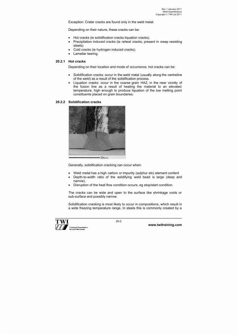
7/22/2019 CSWIP 3.2 LATEST WIS10-Mar-2011
http://slidepdf.com/reader/full/cswip-32-latest-wis10-mar-2011 232/303
Rev 1 January 2011Weld Imperfections
Copyright TWI Ltd 2011
www.twitraining.com 20-2
Exception: Crater cracks are found only in the weld metal.
Depending on their nature, these cracks can be:
Hot cracks (ie solidification cracks liquation cracks).
Precipitation induced cracks (ie reheat cracks, present in creep resistingsteels).
Cold cracks (ie hydrogen induced cracks).
Lamellar tearing.
20.2.1 Hot cracks
Depending on their location and mode of occurrence, hot cracks can be:
Solidification cracks: occur in the weld metal (usually along the centrelineof the weld) as a result of the solidification process.
Liquation cracks: occur in the coarse grain HAZ, in the near vicinity ofthe fusion line as a result of heating the material to an elevatedtemperature, high enough to produce liquation of the low melting pointconstituents placed on grain boundaries.
20.2.2 Solidification cracks
Generally, solidification cracking can occur when:
Weld metal has a high carbon or impurity (sulphur etc) element content
Depth-to-width ratio of the solidifying weld bead is large (deep andnarrow).
Disruption of the heat flow condition occurs, eg stop/start condition.
The cracks can be wide and open to the surface like shrinkage voids orsub-surface and possibly narrow.
Solidification cracking is most likely to occur in compositions, which result in
a wide freezing temperature range. In steels this is commonly created by a

7/22/2019 CSWIP 3.2 LATEST WIS10-Mar-2011
http://slidepdf.com/reader/full/cswip-32-latest-wis10-mar-2011 233/303
Rev 1 January 2011Weld Imperfections
Copyright TWI Ltd 2011
www.twitraining.com 20-3
higher than normal content of carbon and impurity elements such as sulphurand phosphorus. These elements segregate during solidification, so thatintergranular liquid films remain after the bulk of the weld has solidified. Thethermal shrinkage of the cooling weld bead can cause these to rupture andform a crack.
It is important that the welding fabricator does not weld on or near metalsurfaces covered with scale or which have been contaminated with oil orgrease. Scale can have high sulphur content and oil and grease can supplyboth carbon and sulphur. Contamination with low melting point metals suchas copper, tin, lead and zinc should also be avoided.
20.2.3 Hydrogen induced cracks
Root (underbead) crack. Toe crack.
Hydrogen induced cracking occurs primarily in the grain-coarsened region ofthe HAZ, and is also known as cold cracking, delayed cracking orunderbead/toe cracking. Underbead cracking lies parallel to the fusionboundary, and its path is usually a combination of intergranular andtransgranular cracking. The direction of the principal residual tensile stresscan, for toe cracks, cause the crack path to grow progressively away from

7/22/2019 CSWIP 3.2 LATEST WIS10-Mar-2011
http://slidepdf.com/reader/full/cswip-32-latest-wis10-mar-2011 234/303
Rev 1 January 2011Weld Imperfections
Copyright TWI Ltd 2011
www.twitraining.com 20-4
the fusion boundary towards a region of lower sensitivity to hydrogencracking, when this happens, the crack growth rate decreases andeventually arrests.
A combination of four factors is necessary to cause HAZ hydrogen cracking:
1 Hydrogen level > 15ml/100g of weld metal deposited.2 Stress > 0.5 of the yield stress.3 Temperature < 3000C.4 Susceptible microstructure > 400HV hardness.
If any one factor is not satisfied, cracking is prevented. Therefore, crackingcan be avoided through control of one or more of these factors.
Apply preheat (to slow down the cooling rate and thus avoid theformation of susceptible microstructures).
Maintain a specific interpass temperature (same effect as preheat).
Post heat on completion of welding (to reduce the hydrogen content byallowing hydrogen to effuse from the weld area).
Apply PWHT (to reduce residual stress and eliminate susceptiblemicrostructures).
Reduce weld metal hydrogen by proper selection of welding process/consumable (eg use TIG welding instead MMA, use basic coveredelectrodes instead cellulose ones).
Use multi-run instead single-run technique (eliminate susceptible
microstructures by means of self tempering effect, reduce the hydrogencontent by allowing hydrogen to effuse from the weld area).
Use a temper bead or hot pass technique (same effect as above).
Use austenitic or nickel filler (avoid susceptible microstructure formationand allow hydrogen diffusion out of critical areas).
Use dry shielding gases (reduce hydrogen content).
Clean joint from rust (avoid hydrogen contamination from moisturepresent in the rust).
Reduce residual stress.
Blend the weld profile (reduce stress concentration at the toes of the
weld).

7/22/2019 CSWIP 3.2 LATEST WIS10-Mar-2011
http://slidepdf.com/reader/full/cswip-32-latest-wis10-mar-2011 235/303
Rev 1 January 2011Weld Imperfections
Copyright TWI Ltd 2011
www.twitraining.com 20-5
20.2.4 Lamellar tearing
Lamellar tearing occurs only in rolled steel products (primarily plates) and itsmain distinguishing feature is that the cracking has a terraced appearance.
Cracking occurs in joints where:
A thermal contraction strain occurs in the through-thickness direction ofsteel plate.
Non-metallic inclusions are present as very thin platelets, with theirprincipal planes parallel to the plate surface.
Contraction strain imposed on the planar non-metallic inclusions results inprogressive decohesion to form the roughly rectangular holes which are thehorizontal parts of the cracking, parallel to the plate surface. With furtherstrain, the vertical parts of the cracking are produced, generally by ductileshear cracking. These two stages create the terraced appearance of thesecracks.
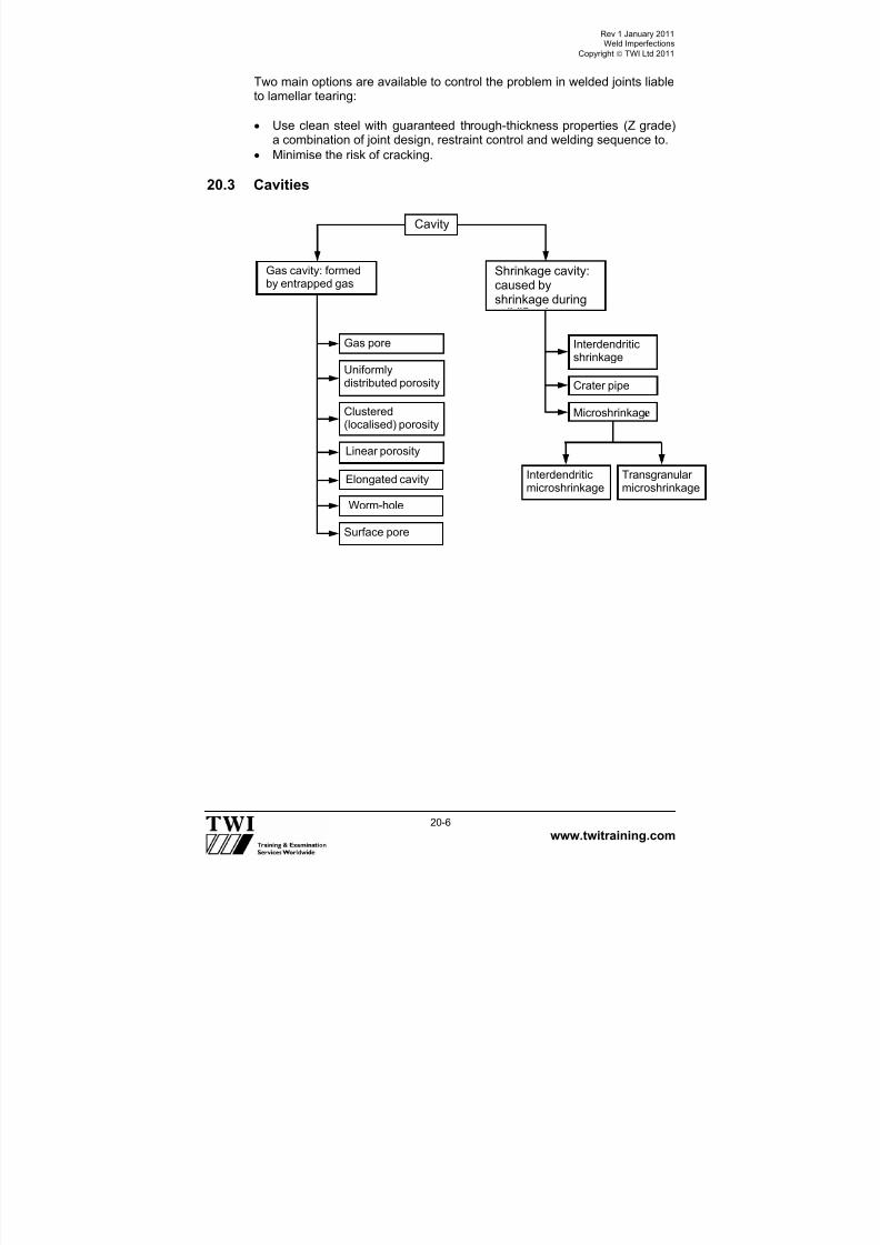
7/22/2019 CSWIP 3.2 LATEST WIS10-Mar-2011
http://slidepdf.com/reader/full/cswip-32-latest-wis10-mar-2011 236/303
Rev 1 January 2011Weld Imperfections
Copyright TWI Ltd 2011
www.twitraining.com 20-6
Two main options are available to control the problem in welded joints liableto lamellar tearing:
Use clean steel with guaranteed through-thickness properties (Z grade)a combination of joint design, restraint control and welding sequence to.
Minimise the risk of cracking.
20.3 Cavities
Cavity
Shrinkage cavity:caused byshrinkage during
Gas cavity: formedby entrapped gas
Gas pore
Uniformlydistributed porosity
Clustered(localised) porosity
Linear porosity
Elongated cavity
Worm-hole
Surface pore
Interdendriticmicroshrinkage
Transgranularmicroshrinkage
Interdendriticshrinkage
Crater pipe
Microshrinkage

7/22/2019 CSWIP 3.2 LATEST WIS10-Mar-2011
http://slidepdf.com/reader/full/cswip-32-latest-wis10-mar-2011 237/303
Rev 1 January 2011Weld Imperfections
Copyright TWI Ltd 2011
www.twitraining.com 20-7
20.3.1 Gas pore
Description A gas cavity of essentially spherical shape trapped within the weld metal.This gas cavity can be present in various forms:
Isolated.
Uniformly distributed porosity.
Clustered (localised) porosity.
Linear porosity.
Elongated cavity.
Surface pore.
Causes Prevention
Damp fluxes/corroded electrode (MMA) Use dry electrodes in goodcondition
Grease/hydrocarbon/watercontamination of prepared surface
Clean prepared surface
Air entrapment in gas shield (MIG/MAGTIG)
Check hose connections
Incorrect/insufficient deoxidant inelectrode, filler or parent metal
Use electrode with sufficientdeoxidation activity
Too high an arc voltage or arc length Reduce voltage and arc lengthGas evolution from primingpaints/surface treatment
Identify risk of reaction beforesurface treatment is applied
Too high a shielding gas flow rate whichresults in turbulence (MIG/MAG TIG)
Optimise gas flow rate
CommentsNote that porosity can either be localised or finely dispersed voidsthroughout the weld metal.

7/22/2019 CSWIP 3.2 LATEST WIS10-Mar-2011
http://slidepdf.com/reader/full/cswip-32-latest-wis10-mar-2011 238/303
Rev 1 January 2011Weld Imperfections
Copyright TWI Ltd 2011
www.twitraining.com 20-8
20.3.2 Worm holes
DescriptionElongated or tubular cavities formed by entrapped gas during thesolidification of the weld metal; they can occur singly or in groups.
Causes Prevention
Gross contamination ofpreparation surface
Introduce preweld cleaningprocedures
Laminated work surface Replace parent material with anunlaminated piece
Crevices in work surface due to joint geometry
Eliminate joint shapes which producecrevices
CommentsWormholes are caused by the progressive entrapment of gas between thesolidifying metal crystals (dendrites) producing characteristic elongatedpores of circular cross-section. These elongated pores can appear as aherring-bone array on a radiograph. Some of them may break the surface ofthe weld.

7/22/2019 CSWIP 3.2 LATEST WIS10-Mar-2011
http://slidepdf.com/reader/full/cswip-32-latest-wis10-mar-2011 239/303
Rev 1 January 2011Weld Imperfections
Copyright TWI Ltd 2011
www.twitraining.com 20-9
20.3.3 Surface porosity
Description A gas pore that breaks the surface of the weld.
Causes Prevention
Damp or contaminated surface orelectrode
Clean surface and dry electrodes
Low fluxing activity (MIG/MAG) Use a high activity flux
Excess sulphur (particularly free-cutting steels) producing sulphurdioxide
Use high manganese electrode toproduce MnS, note free-cuttingsteels (high sulphur) should notnormally be welded
Loss of shielding gas due to long
arc or high breezes (MIG/MAG)
Improve screening against draughts
and reduce arc lengthToo high a shielding gas flow ratewhich results in turbulence(MIG/MAG TIG)
Optimise gas flow rate
CommentsThe origins of surface porosity are similar to those for uniform porosity.

7/22/2019 CSWIP 3.2 LATEST WIS10-Mar-2011
http://slidepdf.com/reader/full/cswip-32-latest-wis10-mar-2011 240/303
Rev 1 January 2011Weld Imperfections
Copyright TWI Ltd 2011
www.twitraining.com 20-10
20.3.4 Crater pipe
Description
A shrinkage cavity at the end of a weld run. The main cause is shrinkageduring solidification.
Causes Prevention
Lack of welder skill due to usingprocesses with too high a current
Retrain welder
Inoperative crater filler (slope out)(TIG)
Use correct crater filling techniques
CommentsCrater filling is a particular problem in TIG welding due to its low heat input.
To fill the crater for this process it is necessary to reduce the weld current(slope out) in a series of descending steps until the arc is extinguished.
20.4 Solid inclusions
Definition: Solid foreign substances entrapped in the weld metal.
Solidinclusion
Oxide
inclusionMetallicinclusion
Fluxinclusion
Slaginclusion
ClusteredIsolatedLinear Other
Tungsten
Copper
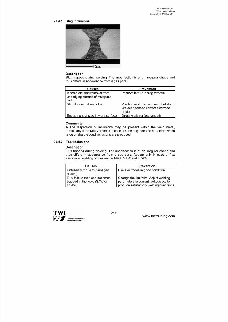
7/22/2019 CSWIP 3.2 LATEST WIS10-Mar-2011
http://slidepdf.com/reader/full/cswip-32-latest-wis10-mar-2011 241/303
Rev 1 January 2011Weld Imperfections
Copyright TWI Ltd 2011
www.twitraining.com 20-11
20.4.1 Slag inclusions
DescriptionSlag trapped during welding. The imperfection is of an irregular shape andthus differs in appearance from a gas pore.
Causes Prevention
Incomplete slag removal fromunderlying surface of multipassweld
Improve inter-run slag removal
Slag flooding ahead of arc Position work to gain control of slag.Welder needs to correct electrodeangle
Entrapment of slag in work surface Dress work surface smooth
Comments A fine dispersion of inclusions may be present within the weld metal,particularly if the MMA process is used. These only become a problem whenlarge or sharp-edged inclusions are produced.
20.4.2 Flux inclusions
DescriptionFlux trapped during welding. The imperfection is of an irregular shape andthus differs in appearance from a gas pore. Appear only in case of flux
associated welding processes (ie MMA, SAW and FCAW).
Causes Prevention
Unfused flux due to damagedcoating
Use electrodes in good condition
Flux fails to melt and becomestrapped in the weld (SAW orFCAW)
Change the flux/wire. Adjust weldingparameters ie current, voltage etc toproduce satisfactory welding conditions

7/22/2019 CSWIP 3.2 LATEST WIS10-Mar-2011
http://slidepdf.com/reader/full/cswip-32-latest-wis10-mar-2011 242/303
Rev 1 January 2011Weld Imperfections
Copyright TWI Ltd 2011
www.twitraining.com 20-12
20.4.3 Oxide inclusions
DescriptionOxides trapped during welding. The imperfection is of an irregular shapeand thus differs in appearance from a gas pore.
Causes Prevention
Heavy mill scale/rust on worksurface
Grind surface prior to welding
Comments A special type of oxide inclusion is puckering. This type of defect occursespecially in the case of aluminium alloys. Gross oxide film enfoldment canoccur due to a combination of unsatisfactory protection from atmosphericcontamination and turbulence in the weld pool.
20.4.4 Tungsten inclusions
DescriptionParticles of tungsten can become embedded during TIG welding. Thisimperfection appears as a light area on radiographs due to the fact thattungsten is denser than the surrounding metal and absorbs larger amountsof X/gamma radiation.
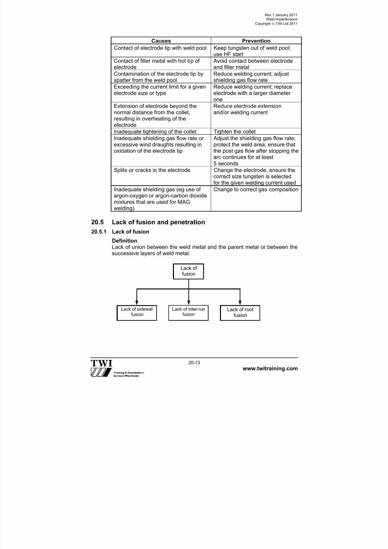
7/22/2019 CSWIP 3.2 LATEST WIS10-Mar-2011
http://slidepdf.com/reader/full/cswip-32-latest-wis10-mar-2011 243/303
Rev 1 January 2011Weld Imperfections
Copyright TWI Ltd 2011
www.twitraining.com 20-13
Causes Prevention
Contact of electrode tip with weld pool Keep tungsten out of weld pool;use HF start
Contact of filler metal with hot tip of
electrode
Avoid contact between electrode
and filler metalContamination of the electrode tip byspatter from the weld pool
Reduce welding current; adjustshielding gas flow rate
Exceeding the current limit for a givenelectrode size or type
Reduce welding current; replaceelectrode with a larger diameterone
Extension of electrode beyond thenormal distance from the collet,resulting in overheating of theelectrode
Reduce electrode extensionand/or welding current
Inadequate tightening of the collet Tighten the collet
Inadequate shielding gas flow rate orexcessive wind draughts resulting inoxidation of the electrode tip
Adjust the shielding gas flow rate;protect the weld area; ensure thatthe post gas flow after stopping thearc continues for at least5 seconds
Splits or cracks in the electrode Change the electrode, ensure thecorrect size tungsten is selectedfor the given welding current used
Inadequate shielding gas (eg use ofargon-oxygen or argon-carbon dioxide
mixtures that are used for MAGwelding)
Change to correct gas composition
20.5 Lack of fusion and penetration
20.5.1 Lack of fusion
DefinitionLack of union between the weld metal and the parent metal or between thesuccessive layers of weld metal.
Lack offusion
Lack of sidewallfusion
Lack of inter-runfusion
Lack of rootfusion

7/22/2019 CSWIP 3.2 LATEST WIS10-Mar-2011
http://slidepdf.com/reader/full/cswip-32-latest-wis10-mar-2011 244/303
Rev 1 January 2011Weld Imperfections
Copyright TWI Ltd 2011
www.twitraining.com 20-14
Lack of sidewall fusion
DescriptionLack of union between the weld and parent metal at one or both sides of theweld.
Causes Prevention
Low heat input to weld Increase arc voltage and/or weldingcurrent; decrease travel speed
Molten metal flooding ahead ofarc
Improve electrode angle and workposition; increase travel speed
Oxide or scale on weldpreparation
Improve edge preparation procedure
Excessive inductance in MAG diptransfer welding
Reduce inductance, even if thisincreases spatter
CommentsDuring welding sufficient heat must be available at the edge of the weld poolto produce fusion with the parent metal.

7/22/2019 CSWIP 3.2 LATEST WIS10-Mar-2011
http://slidepdf.com/reader/full/cswip-32-latest-wis10-mar-2011 245/303
Rev 1 January 2011Weld Imperfections
Copyright TWI Ltd 2011
www.twitraining.com 20-15
Lack of inter-run fusion
Description A lack of union along the fusion line, between the weld beads.
Causes Prevention
Low arc current resulting in low fluidity of weldpool
Increase current
Too high a travel speed Reduce travel speed
Inaccurate bead placement Retrain welder
CommentsLack of inter-run fusion produce crevices between the weld beads andcause local entrapment of slag.

7/22/2019 CSWIP 3.2 LATEST WIS10-Mar-2011
http://slidepdf.com/reader/full/cswip-32-latest-wis10-mar-2011 246/303
Rev 1 January 2011Weld Imperfections
Copyright TWI Ltd 2011
www.twitraining.com 20-16
Lack of root fusion
DescriptionLack of fusion between the weld and parent metal at the root of a weld.
Causes PreventionLow heat input Increase welding current and/or arcvoltage; decrease travel speed
Excessive inductance in MAG diptransfer welding,
Use correct induction setting for theparent metal thickness
MMA electrode too large (lowcurrent density)
Reduce electrode size
Use of vertical down welding Switch to vertical up procedure
Large root face Reduce root face
Small root gap Ensure correct root opening
Incorrect angle or incorrect
electrode manipulation
Use correct electrode angle. Ensure
welder is fully qualified and competentExcessive misalignment at root Ensure correct alignment
20.5.2 Lack of penetration
Lack ofpenetration
Incompletepenetration
Incomplete rootpenetration
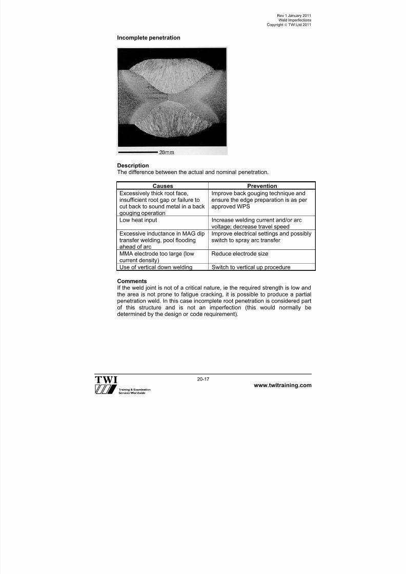
7/22/2019 CSWIP 3.2 LATEST WIS10-Mar-2011
http://slidepdf.com/reader/full/cswip-32-latest-wis10-mar-2011 247/303
Rev 1 January 2011Weld Imperfections
Copyright TWI Ltd 2011
www.twitraining.com 20-17
Incomplete penetration
DescriptionThe difference between the actual and nominal penetration.
Causes Prevention
Excessively thick root face,insufficient root gap or failure tocut back to sound metal in a back
gouging operation
Improve back gouging technique andensure the edge preparation is as perapproved WPS
Low heat input Increase welding current and/or arcvoltage; decrease travel speed
Excessive inductance in MAG diptransfer welding, pool floodingahead of arc
Improve electrical settings and possiblyswitch to spray arc transfer
MMA electrode too large (lowcurrent density)
Reduce electrode size
Use of vertical down welding Switch to vertical up procedure
CommentsIf the weld joint is not of a critical nature, ie the required strength is low andthe area is not prone to fatigue cracking, it is possible to produce a partialpenetration weld. In this case incomplete root penetration is considered partof this structure and is not an imperfection (this would normally bedetermined by the design or code requirement).

7/22/2019 CSWIP 3.2 LATEST WIS10-Mar-2011
http://slidepdf.com/reader/full/cswip-32-latest-wis10-mar-2011 248/303
Rev 1 January 2011Weld Imperfections
Copyright TWI Ltd 2011
www.twitraining.com 20-18
Incomplete root penetration
DescriptionOne or both fusion faces of the root are not melted. When examined fromthe root side, you can clearly see one or both of the root edges unmelted.
Causes and preventionSame as for lack of root fusion.

7/22/2019 CSWIP 3.2 LATEST WIS10-Mar-2011
http://slidepdf.com/reader/full/cswip-32-latest-wis10-mar-2011 249/303
Rev 1 January 2011Weld Imperfections
Copyright TWI Ltd 2011
www.twitraining.com 20-19
20.6 Imperfect shape and dimensions
20.6.1 Undercut
Description An irregular groove at the toe of a run in the parent metal or in a previouslydeposited weld metal due to welding. It is characterised by its depth, lengthand sharpness.
Causes Prevention
Melting of top edge due to highwelding current (especially at freeedge) or high travel speed
Reduce power input, especiallyapproaching a free edge whereoverheating can occur
Attempting a fillet weld in horizontalvertical position (PB) with leg length
>9mm
Weld in the flat position or use multi-run techniques
Excessive/incorrect weaving Reduce weaving width or switch tomulti-runs
Incorrect electrode angle Direct arc towards thicker member
Incorrect shielding gas selection(MAG)
Ensure correct gas mixture formaterial type and thickness (MAG)
Undercut
Continuousundercut
Intermittentundercut
Inter runundercut

7/22/2019 CSWIP 3.2 LATEST WIS10-Mar-2011
http://slidepdf.com/reader/full/cswip-32-latest-wis10-mar-2011 250/303
Rev 1 January 2011Weld Imperfections
Copyright TWI Ltd 2011
www.twitraining.com 20-20
CommentsCare must be taken during weld repairs of undercut to control the heat input.If the bead of a repair weld is too small, the cooling rate following weldingwill be excessive and the parent metal may have an increased hardnessand the weld may be susceptible to hydrogen cracking.
20.6.2 Excess weld metal
DescriptionExcess weld metal is the extra metal that produces excessive convexity infillet welds and a weld thickness greater than the parent metal plate in buttwelds. This feature of a weld is regarded as an imperfection only when the
height of the excess weld metal is greater than a specified limit.
Causes Prevention
Excess arc energy (MAG,SAW)
Reduction of heat input
Shallow edge preparation Deepen edge preparation
Faulty electrode manipulationor build-up sequence
Improve welder skill
Incorrect electrode size Reduce electrode size
Too slow a travel speed Ensure correct travel speed is used
Incorrect electrode angle Ensure correct electrode angle is usedWrong polarity used (electrodepolarity DC-VE (MMA, SAW )
Ensure correct polarity ie DC +VENote DC-VE must be used for TIG
CommentsThe term reinforcement used to designate this feature of the weld ismisleading since the excess metal does not normally produce a strongerweld in a butt joint in ordinary steel. This imperfection can become aproblem, as the angle of the weld toe can be sharp, leading to an increasedstress concentration at the toes of the weld and fatigue cracking.

7/22/2019 CSWIP 3.2 LATEST WIS10-Mar-2011
http://slidepdf.com/reader/full/cswip-32-latest-wis10-mar-2011 251/303
Rev 1 January 2011Weld Imperfections
Copyright TWI Ltd 2011
www.twitraining.com 20-21
20.6.3 Excess penetration
DescriptionProjection of the root penetration bead beyond a specified limit can be localor continuous.
Causes Prevention
Weld heat input too high Reduce arc voltage and/or weldingcurrent; increase welding speed
Incorrect weld preparation ieexcessive root gap, thin edgepreparation, lack of backing
Improve workpiece preparation
Use of electrode unsuited towelding position
Use correct electrode for position
Lack of welder skill Retrain welder
CommentsNote that the maintenance of a penetration bead having uniform dimensionsrequires a great deal of skill, particularly in pipe butt welding. This can bemade more difficult if there is restricted access to the weld or a narrowpreparation. The use of permanent or temporary backing bars can be usedto assist in the control of penetration.

7/22/2019 CSWIP 3.2 LATEST WIS10-Mar-2011
http://slidepdf.com/reader/full/cswip-32-latest-wis10-mar-2011 252/303
Rev 1 January 2011Weld Imperfections
Copyright TWI Ltd 2011
www.twitraining.com 20-22
20.6.4 Overlap
Description An imperfection at the toe of a weld caused by metal flowing on to thesurface of the parent metal without fusing to it.
Causes Prevention
Poor electrode manipulation(MMA)
Retrain welder
High heat input/low travel speedcausing surface flow of fillet welds
Reduce heat input or limit leg size to9mm maximum leg size for single passfillets.
Incorrect positioning of weld Change to flat position
Wrong electrode coating typeresulting in too high a fluidity
Change electrode coating type to amore suitable fast freezing type whichis less fluid
CommentsFor a fillet weld overlap is often associated with undercut, as if the weld poolis too fluid the top of the weld will flow away to produce undercut at the top
and overlap at the base. If the volume of the weld pool is too large in case ofa fillet weld in horizontal-vertical position (PB), weld metal will collapse dueto gravity, producing both defects (undercut at the top and overlap at thebase). This defect is called sagging.
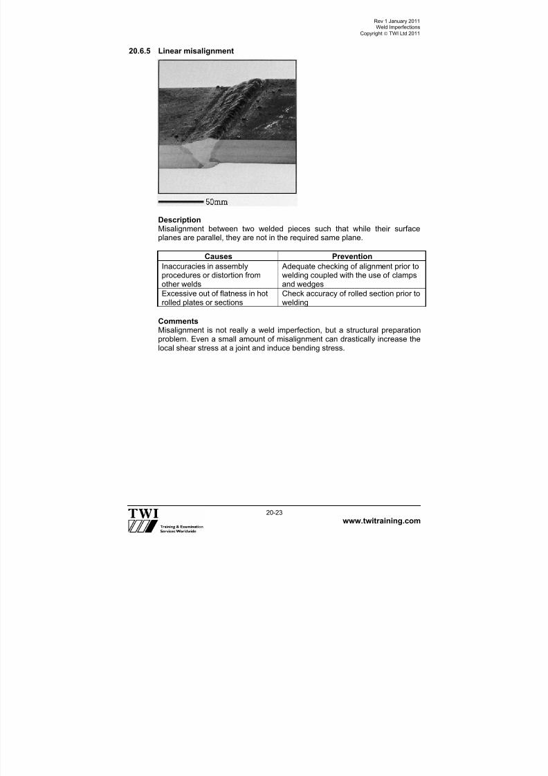
7/22/2019 CSWIP 3.2 LATEST WIS10-Mar-2011
http://slidepdf.com/reader/full/cswip-32-latest-wis10-mar-2011 253/303
Rev 1 January 2011Weld Imperfections
Copyright TWI Ltd 2011
www.twitraining.com 20-23
20.6.5 Linear misalignment
DescriptionMisalignment between two welded pieces such that while their surfaceplanes are parallel, they are not in the required same plane.
Causes Prevention
Inaccuracies in assemblyprocedures or distortion from
other welds
Adequate checking of alignment prior towelding coupled with the use of clamps
and wedgesExcessive out of flatness in hotrolled plates or sections
Check accuracy of rolled section prior towelding
CommentsMisalignment is not really a weld imperfection, but a structural preparationproblem. Even a small amount of misalignment can drastically increase thelocal shear stress at a joint and induce bending stress.

7/22/2019 CSWIP 3.2 LATEST WIS10-Mar-2011
http://slidepdf.com/reader/full/cswip-32-latest-wis10-mar-2011 254/303
Rev 1 January 2011Weld Imperfections
Copyright TWI Ltd 2011
www.twitraining.com 20-24
20.6.6 Angular distortion
DescriptionMisalignment between two welded pieces such that their surface planes are
not parallel or at the intended angle.
Causes and preventionSame as for linear misalignment.
20.6.7 Incompletely filled groove
Description A continuous or intermittent channel in the surface of a weld due toinsufficient deposition of weld filler metal.
Causes Prevention
Insufficient weld metal Increase the number of weld runs
Irregular weld bead surface Retrain welder
CommentsThis imperfection differs from undercut, as incompletely filled groovereduces the load bearing capacity of a weld, whereas undercut produces asharp stress-raising notch at the edge of a weld.

7/22/2019 CSWIP 3.2 LATEST WIS10-Mar-2011
http://slidepdf.com/reader/full/cswip-32-latest-wis10-mar-2011 255/303
Rev 1 January 2011Weld Imperfections
Copyright TWI Ltd 2011
www.twitraining.com 20-25
20.6.8 Irregular width
DescriptionExcessive variation in width of the weld.
Causes Prevention
Severe arc blow Switch from DC to AC, keep an as shortas possible arc length
Irregular weld bead surface Retrain welder
Comments Although this imperfection may not affect the integrity of completed weld, itcan affect the width of HAZ and reduce the load-carrying capacity of the joint (in case of fine-grained structural steels) or impair corrosion resistance(in case of duplex stainless steels).
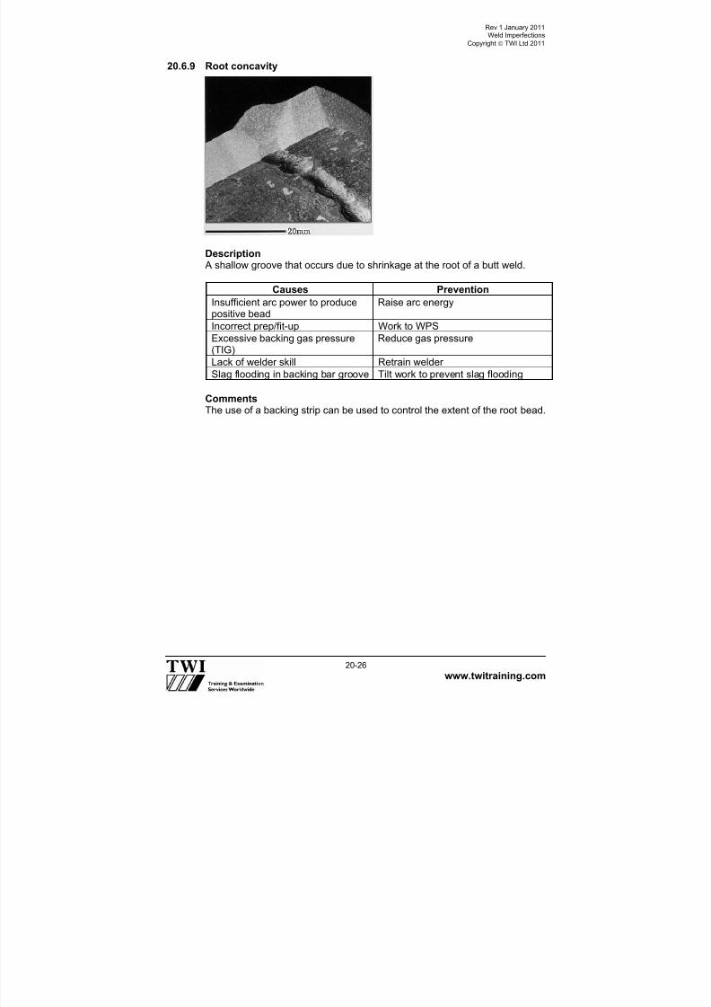
7/22/2019 CSWIP 3.2 LATEST WIS10-Mar-2011
http://slidepdf.com/reader/full/cswip-32-latest-wis10-mar-2011 256/303
Rev 1 January 2011Weld Imperfections
Copyright TWI Ltd 2011
www.twitraining.com 20-26
20.6.9 Root concavity
Description A shallow groove that occurs due to shrinkage at the root of a butt weld.
Causes Prevention
Insufficient arc power to producepositive bead
Raise arc energy
Incorrect prep/fit-up Work to WPS
Excessive backing gas pressure(TIG)
Reduce gas pressure
Lack of welder skill Retrain welder
Slag flooding in backing bar groove Tilt work to prevent slag flooding
CommentsThe use of a backing strip can be used to control the extent of the root bead.

7/22/2019 CSWIP 3.2 LATEST WIS10-Mar-2011
http://slidepdf.com/reader/full/cswip-32-latest-wis10-mar-2011 257/303
Rev 1 January 2011Weld Imperfections
Copyright TWI Ltd 2011
www.twitraining.com 20-27
20.6.10 Burn through
Description A collapse of the weld pool resulting in a hole in the weld.
Causes Prevention
Insufficient travel speed Increase the travel speed
Excessive welding current Reduce welding current
Lack of welder skill Retrain welderExcessive grinding of root face More care taken, retrain welder
Excessive root gap Ensure correct fit up
CommentsThis is a gross imperfection, which occurs basically due to lack of welderskill. It can be repaired by bridging the gap formed into the joint, but requiresa great deal of attention.
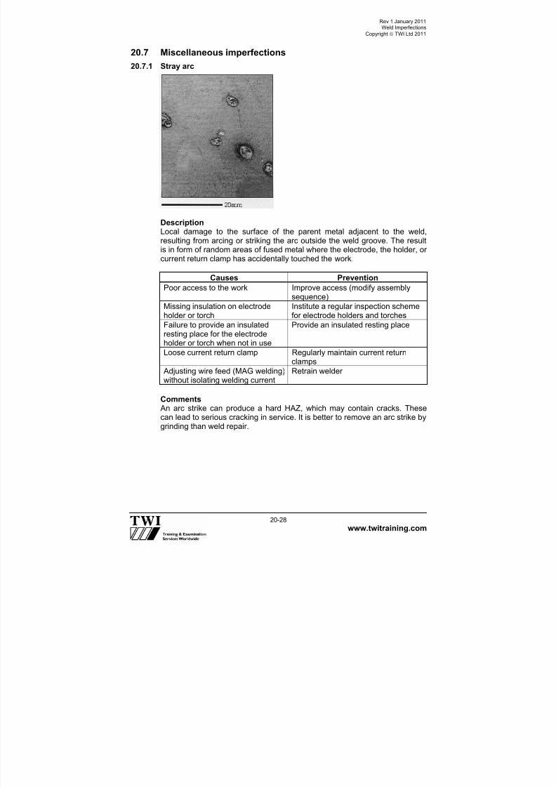
7/22/2019 CSWIP 3.2 LATEST WIS10-Mar-2011
http://slidepdf.com/reader/full/cswip-32-latest-wis10-mar-2011 258/303
Rev 1 January 2011Weld Imperfections
Copyright TWI Ltd 2011
www.twitraining.com 20-28
20.7 Miscellaneous imperfections
20.7.1 Stray arc
DescriptionLocal damage to the surface of the parent metal adjacent to the weld,resulting from arcing or striking the arc outside the weld groove. The resultis in form of random areas of fused metal where the electrode, the holder, orcurrent return clamp has accidentally touched the work.
Causes Prevention
Poor access to the work Improve access (modify assemblysequence)
Missing insulation on electrodeholder or torch
Institute a regular inspection schemefor electrode holders and torches
Failure to provide an insulatedresting place for the electrodeholder or torch when not in use
Provide an insulated resting place
Loose current return clamp Regularly maintain current returnclamps
Adjusting wire feed (MAG welding)without isolating welding current
Retrain welder
Comments An arc strike can produce a hard HAZ, which may contain cracks. Thesecan lead to serious cracking in service. It is better to remove an arc strike bygrinding than weld repair.

7/22/2019 CSWIP 3.2 LATEST WIS10-Mar-2011
http://slidepdf.com/reader/full/cswip-32-latest-wis10-mar-2011 259/303
Rev 1 January 2011Weld Imperfections
Copyright TWI Ltd 2011
www.twitraining.com 20-29
20.7.2 Spatter
DescriptionGlobules of weld metal or filler metal expelled during welding and adheringto the surface of parent metal or solidified weld metal.
Causes Prevention
High arc current Reduce arc current
Long arc length Reduce Arc Length
Magnetic arc blow Reduce arc length or switch to ACpower
Incorrect settings for GMAWprocess
Modify electrical settings (but becareful to maintain full fusion!)
Damp electrodes Use dry electrodes
Wrong selection of shielding gas(100% CO2)
Increase argon content if possible,however too high a % of argon maylead to lack of penetration
CommentsSpatter in itself is a cosmetic imperfection and does not affect the integrity ofthe weld. However as it is usually caused by an excessive welding current, it
is a sign that the welding conditions are not ideal and so there are usuallyother associated problems within the structure ie high heat input. Note thatsome spatter is always produced by open arc consumable electrode weldingprocesses. Anti-spatter compounds can be used on the parent metal toreduce sticking and the spatter can then be scraped off.
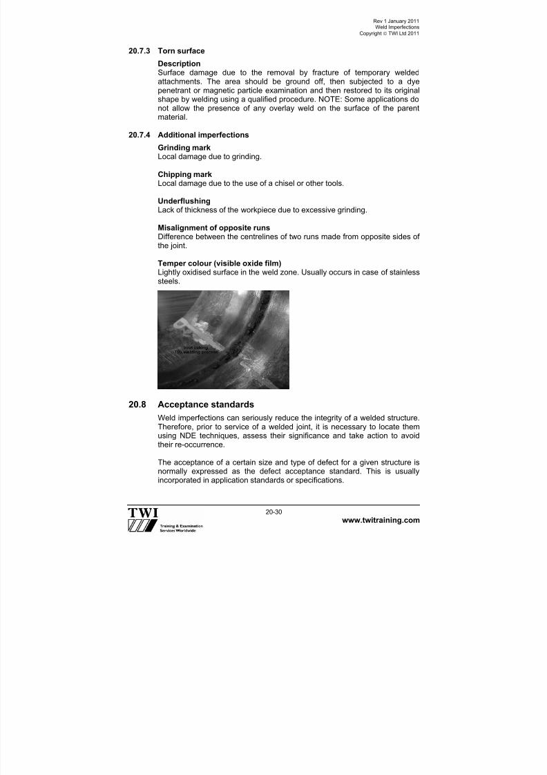
7/22/2019 CSWIP 3.2 LATEST WIS10-Mar-2011
http://slidepdf.com/reader/full/cswip-32-latest-wis10-mar-2011 260/303
Rev 1 January 2011Weld Imperfections
Copyright TWI Ltd 2011
www.twitraining.com 20-30
20.7.3 Torn surface
DescriptionSurface damage due to the removal by fracture of temporary weldedattachments. The area should be ground off, then subjected to a dyepenetrant or magnetic particle examination and then restored to its originalshape by welding using a qualified procedure. NOTE: Some applications donot allow the presence of any overlay weld on the surface of the parentmaterial.
20.7.4 Additional imperfections
Grinding markLocal damage due to grinding.
Chipping markLocal damage due to the use of a chisel or other tools.
UnderflushingLack of thickness of the workpiece due to excessive grinding.
Misalignment of opposite runsDifference between the centrelines of two runs made from opposite sides ofthe joint.
Temper colour (visible oxide film)Lightly oxidised surface in the weld zone. Usually occurs in case of stainlesssteels.
20.8 Acceptance standards
Weld imperfections can seriously reduce the integrity of a welded structure.Therefore, prior to service of a welded joint, it is necessary to locate themusing NDE techniques, assess their significance and take action to avoidtheir re-occurrence.
The acceptance of a certain size and type of defect for a given structure isnormally expressed as the defect acceptance standard. This is usually
incorporated in application standards or specifications.

7/22/2019 CSWIP 3.2 LATEST WIS10-Mar-2011
http://slidepdf.com/reader/full/cswip-32-latest-wis10-mar-2011 261/303
Rev 1 January 2011Weld Imperfections
Copyright TWI Ltd 2011
www.twitraining.com 20-31
All normal weld imperfection acceptance standards totally reject cracks.However, in exceptional circumstances, and subject to the agreement of allparties, cracks may be allowed to remain if it can be demonstrated beyonddoubt that they will not lead to failure. This can be difficult to establish andusually involves fracture mechanics measurements and calculations.
It is important to note that the levels of acceptability vary between differentapplications, and in most cases vary between different standards for thesame application. Consequently, when inspecting different jobs it isimportant to use the applicable standard or specification quoted in thecontract.
Once unacceptable weld imperfections have been found, they have to beremoved. If the weld imperfection is at the surface, the first consideration iswhether it is of a type, which is normally shallow enough to be repaired bysuperficial dressing. Superficial implies that, after removal of the defect, the
remaining material thickness is sufficient not to require the addition of furtherweld metal.
If the defect is too deep, it must be removed by some means and new weldmetal added to ensure a minimum design throat thickness.
Replacing removed metal or weld repair (as in filling an excavation or re-making a weld joint) has to be done in accordance with an approvedprocedure. The rigor with which this procedure is qualified will depend onthe application standard for the job. In some cases it will be acceptable touse a procedure qualified for making new joints whether filling an excavationor making a complete joint. If the level of reassurance required is higher, thequalification will have to be made using an exact simulation of a welded joint, which is excavated and then refilled using a specified method. In eithercase, qualification inspection and testing will be required in accordance withthe application standard.

7/22/2019 CSWIP 3.2 LATEST WIS10-Mar-2011
http://slidepdf.com/reader/full/cswip-32-latest-wis10-mar-2011 262/303
Section 21
Weld Repairs

7/22/2019 CSWIP 3.2 LATEST WIS10-Mar-2011
http://slidepdf.com/reader/full/cswip-32-latest-wis10-mar-2011 263/303
Rev 1 January 2011Weld Repairs
Copyright TWI Ltd 2011
www.twitraining.com 21-1
21 Weld Repairs
Weld repairs can be divided into two specific areas:
1 Production repairs.
2 In service repairs.
The reasons for making a repair are many and varied. Typically, they rangefrom the removal of weld defects induced during manufacture to a quick andtemporary running-repair to an item of production plant. In these terms, thesubject of welding repairs is also wide and varied and often confused withmaintenance and refurbishment where the work can be scheduled.
With planned maintenance and refurbishment, sufficient time can be allowedto enable the tasks to be completed without production pressures beingapplied. In contrast, repairs are usually unplanned and may result in
shortcuts being taken to allow the production programme to continue. It is,therefore, advisable for a fabricator to have an established policy on repairsand to have repair methods and procedures in place.
The manually controlled welding processes are the easiest to use,particularly if it is a local repair or one to be carried out on-site. Probably themost frequently used of these processes is manual metal arc (MMA) as thisis versatile, portable and readily applicable to many alloys because of thewide range of off-the-shelf consumables. Repairs almost always result inhigher residual stresses and increased distortion compared with first timewelds. With carbon-manganese and low/medium alloy steels, the application
of preheat and post-weld heat treatments may be required.
There are a number of key factors that need to be considered beforeundertaking any repair.
The most important being a judgement as to whether it is financiallyworthwhile. Before this judgement can be made, the fabricator needs toanswer the following questions:
1 Can structural integrity be achieved if the item is repaired?2 Are there any alternatives to welding?3 What caused the defect and is it likely to happen again?4 How is the defect to be removed and what welding process is to be
used?5 Which non-destructive testing (NDT) is required to ensure complete
removal of the defect?6 Will the welding procedures require approval/re-approval?7 What will be the effect of welding distortion and residual stress?8 Will heat treatment be required?9 What NDT is required and how can acceptability of the repair be
demonstrated?
10 Will approval of the repair be required - if yes, how and by whom?
7/22/2019 CSWIP 3.2 LATEST WIS10-Mar-2011
http://slidepdf.com/reader/full/cswip-32-latest-wis10-mar-2011 264/303
Rev 1 January 2011Weld Repairs
Copyright TWI Ltd 2011
www.twitraining.com 21-2
Although a weld repair may be a relatively straightforward activity, in manyinstances it can be quite complex and various engineering disciplines mayneed to be involved to ensure a successful outcome.
It is recommended that there be an ongoing analysis of the types of defect
carried out by the Q/C department to discover the likely reason for theiroccurrence, (Material/process or skill related.)
In general terms, a welding repair involves:
1 A detailed assessment to find out the extremity of the defect. This mayinvolve the use of a surface or sub-surface NDT methods.
2 Cleaning the repair area, (removal of paint grease etc).3 Once established the excavation site must be clearly identified and
marked out.4 An excavation procedure may be required (method used ie grinding, arc-
air gouging, preheat requirements etc).5 NDT should be used to locate the defect and confirm its removal.6 A welding repair procedure/method statement with the appropriate*
welding process, consumable, technique, controlled heat input andinterpass temperatures etc will need to be approved.
7 Use of approved welders.8 Dressing the weld and final visual.9 NDT procedure/technique prepared and carried out to ensure that the
defect has been successfully removed and repaired.10 Any post repair heat treatment requirements.11 Final NDT procedure/technique prepared and carried out after heat
treatment requirements.12 Applying protective treatments (painting etc as required).
(*Appropriate’ means suitable for the alloys being repaired and may notapply in specific situations)
21.1 Production repairs
Repairs are usually identified during production inspection and evaluation ofthe reports is usually carried out by the Welding Inspector, or NDT operator.Discontinuities in the welds are only classed as defects when they are
outside the permitted range permitted by the applied code or standard.
Before the repair can commence, a number of elements need to be fulfilled.
21.1.1 Analysis
As this defect is surface breaking and has occurred at the fusion face theproblem could be cracking or lack of sidewall fusion. If the defect is found tobe cracking the cause may be associated with the material or the weldingprocedure, however if the defect is lack of sidewall fusion this can beapportioned to the lack of skill of the welder.

7/22/2019 CSWIP 3.2 LATEST WIS10-Mar-2011
http://slidepdf.com/reader/full/cswip-32-latest-wis10-mar-2011 265/303
Rev 1 January 2011Weld Repairs
Copyright TWI Ltd 2011
www.twitraining.com 21-3
21.1.2 Assessment
In this particular case as the defect is open to the surface, magnetic particleinspection (MPI) or dye penetrant inspection (DPI) may be used to gaugethe length of the defect and ultrasonic testing (U/T) used to gauge the depth.
A typical defect is shown below:
Plan view of defect
21.1.3 Excavation
If a thermal method of excavation is being used ie arc-air gouging it may bea requirement to qualify a procedure as the heat generated may have anaffect on the metallurgical structure, resulting in the risk of cracking in the
weld or parent material

7/22/2019 CSWIP 3.2 LATEST WIS10-Mar-2011
http://slidepdf.com/reader/full/cswip-32-latest-wis10-mar-2011 266/303
Rev 1 January 2011Weld Repairs
Copyright TWI Ltd 2011
www.twitraining.com 21-4
To prevent cracking it may be necessary to apply a preheat.
The depth to width ratio shall not be less than 1 (depth) to 1 (width) ideally 1to 1.5 would be recommended (ratio: depth 1 to the width 1.5).
Side view of excavation for slight sub surface defect.
Side view of excavation for deep defect.
Side view of excavation for full root repair.
D
W
D
W
D
W

7/22/2019 CSWIP 3.2 LATEST WIS10-Mar-2011
http://slidepdf.com/reader/full/cswip-32-latest-wis10-mar-2011 267/303
Rev 1 January 2011Weld Repairs
Copyright TWI Ltd 2011
www.twitraining.com 21-5
21.1.4 Cleaning of the excavation
At this stage grinding of the repair area is important, due to the risk ofcarbon becoming impregnated into the weld metal/parent material.
It should be ground back typically 3-4mm to bright metal.
Confirmation of excavation At this stage NDT should be used to confirm that the defect has been
completely excavated from the area.

7/22/2019 CSWIP 3.2 LATEST WIS10-Mar-2011
http://slidepdf.com/reader/full/cswip-32-latest-wis10-mar-2011 268/303
Rev 1 January 2011Weld Repairs
Copyright TWI Ltd 2011
www.twitraining.com 21-6
21.1.5 Re-welding of the excavation
Prior to re-welding of the excavation a detailed repair welding procedure/method statement shall be approved.
21.1.6 NDT confirmation of successful repair
After the excavation has been filled the weldment should then undergo acomplete retest using the same NDT techniques as previously used toestablish the original repair, this is carried out to ensure no further defectshave been introduced by the repair welding process. NDT may also need tobe further applied after any additional post-weld heat treatment has beencarried out.
21.2 In-service repairsMost in-service repairs can be of a very complex nature, as the componentis very likely to be in a different welding position and condition than it wasduring production. It may also have been in contact with toxic or combustiblefluids hence a permit to work will need to be sought prior to any work beingcarried out. The repair welding procedure may look very different to theoriginal production procedure due to changes in these elements.
Other factors may also be taken into consideration, such as the effect ofheat on any surrounding areas of the component ie electrical components,or materials that may become damaged by the repair procedure. This mayalso include difficulty in carrying out any required pre- or post-welding heattreatments and a possible restriction of access to the area to be repaired.For large fabrications it is likely that the repair must also take place on-siteand without a shut down of operations, which may bring other elements thatneed to be considered.
Repair of in service defects may require consideration of these and manyother factors, and as such are generally considered more complicated thanproduction repairs.
Typical side view of weld repair

7/22/2019 CSWIP 3.2 LATEST WIS10-Mar-2011
http://slidepdf.com/reader/full/cswip-32-latest-wis10-mar-2011 269/303
Rev 1 January 2011Weld Repairs
Copyright TWI Ltd 2011
www.twitraining.com 21-7
Joining technologies often play a vital role in the repair and maintenance ofstructures. Parts can be replaced, worn or corroded parts can be built up,and cracks can be repaired.
When a repair is required it is important to determine two things: firstly, the
reason for failure and, secondly, can the component actually be repaired?The latter point infers that the material type is known. For metals,particularly those to be welded, the chemical composition is vitally important.Failure modes often indicate the approach required to make a sound repair.When the cause-effect analysis, however simple, is not followed through it isoften the case that the repair is unsafe - sometimes disastrously so.
In many instances, the Standard or Code used to design the structure willdefine the type of repair that can be carried out and will also give guidanceon the methods to be followed. Standards imply that when designing ormanufacturing a new product it is important to consider a maintenance
regime and repair procedures. Repairs may be required during manufactureand this situation should also be considered.
Normally, there is more than one way of making a repair. For example,cracks in cast iron might be held together or repaired by: pinning, bolting,riveting, welding, or brazing. The method chosen will depend on factorssuch as the reason for the failure, the material composition and cleanliness,the environment and the size and shape of the component.
It is very important that repair and maintenance welding are not regardedas activities, which are simple or straightforward. In many instances a repair
may seem undemanding but the consequences of getting it wrong can becatastrophic failure with disastrous consequences.
Is welding the best method of repair?If repair is called for because a component has a local irregularity or ashallow defect, grinding out any defects and blending to a smooth contourmight well be acceptable. It will certainly be preferable if the steel has poorweldability or if fatigue loading is severe. It is often better to reduce the so-called factor of safety slightly, than to risk putting defects, stressconcentrations and residual stresses into a brittle material.
In fact brittle materials - which can include some steels (particularly in thicksections) as well as cast irons - may not be able to withstand the residualstresses imposed by heavy weld repairs, particularly if defects are not allremoved, leaving stress concentrations to initiate cracking.
Is the repair really like earlier repairs?Repairs of one sort may have been routine for many years. It is important,however, to check that the next one is not subtly different. For example, thesection thickness may be greater; the steel to be repaired may be differentand less weldable, or the restraint higher. If there is any doubt, answer theremaining questions.

7/22/2019 CSWIP 3.2 LATEST WIS10-Mar-2011
http://slidepdf.com/reader/full/cswip-32-latest-wis10-mar-2011 270/303
Rev 1 January 2011Weld Repairs
Copyright TWI Ltd 2011
www.twitraining.com 21-8
What is the composition and weldability of the base metal?The original drawings will usually give some idea of the steel involved,although the specification limits may then have been less stringent, and thespecification may not give enough compositional details to be helpful. Ifsulphur-bearing free-machining steel is involved, it could give hot cracking
problems during welding.
If there is any doubt about the composition, a chemical analysis should becarried out. It is important to analyse for all elements, which may affectweldability (Ni, Cr, Mo, Cu, V, Nb and B) as well as those usually, specified(C, S, P, Si and Mn).
A small cost spent on analysis could prevent a valuable component beingruined by ill-prepared repairs or, save money by reducing or avoiding theneed for preheat if the composition were leaner than expected. Once thecomposition is known, a welding procedure can be devised
What strength is required from the repair?The higher the yield strength of the repair weld metal, the greater will be theresidual stress level on completion of welding, the greater the risk ofcracking, the greater the clamping needed to avoid distortion and moredifficulty in formulating the welding procedure. In any case, the practical limitfor the yield strength of conventional steel weld metals is about 1000N/mm2.
Can preheat be tolerated?Not only does a high level of preheat make conditions more difficult for thewelder; the parent steel can be damaged if it has been tempered at a lowtemperature. In other cases the steel being repaired may contain items,which are damaged by excessive heating. Preheat levels can be reduced byusing consumables of ultra-low hydrogen content or by non-ferritic weldmetals. Of these, austenitic electrodes may need some preheat, but themore expensive nickel alloys usually do not. However, the latter may besensitive to high sulphur and phosphorus contents in the parent steel ifdiluted into the weld metal.
Can softening or hardening of the heat affected zone (HAZ)be tolerated?
Softening of the HAZ is likely in very high strength steels, particularly if theyhave been tempered at low temperatures. Such softening cannot beavoided, but its extent can be minimised. Hard HAZs are particularlyvulnerable where service conditions can lead to stress corrosion. Solutionscontaining H2S (hydrogen sulphide) may demand hardness’ below 248HV(22HRC) although fresh aerated seawater appears to tolerate up to about450HV. Excessively hard HAZ’s may, therefore, require post-weld heattreatment (PWHT) to soften them but provided cracking has been avoided.

7/22/2019 CSWIP 3.2 LATEST WIS10-Mar-2011
http://slidepdf.com/reader/full/cswip-32-latest-wis10-mar-2011 271/303
Rev 1 January 2011Weld Repairs
Copyright TWI Ltd 2011
www.twitraining.com 21-9
Is PWHT practicable? Although it may be desirable, PWHT may not be possible for the samereasons that preheating is not possible. For large structures, local PWHTmay be possible, but care should be taken to abide by the relevant codes,because it is all too easy to introduce new residual stresses by improperly
executed PWHT.
Is PWHT necessary?PWHT may be needed for one of several reasons, and the reason must beknown before considering whether it can be avoided.
Will the fatigue resistance of the repair be adequate?If the repair is in an area, which is highly stressed by fatigue, and particularlyif the attempted repair is of a fatigue crack, inferior fatigue life can beexpected unless the weld surface is ground smooth and no surface defectsare left. Fillet welds, in which the root cannot be ground smooth, are not
tolerable in areas of high fatigue stress.
Will the repair resist its environment?Besides corrosion, it is important to consider the possibility of stresscorrosion, corrosion fatigue, thermal fatigue and oxidation in service.
Corrosion and oxidation resistance usually requires that the composition ofthe filler metal is at least as noble or oxidation resistant as the parent metal.For corrosion fatigue resistance, the repair weld profile may need to besmoothed.
To resist stress corrosion, PWHT may be necessary to restore the correctmicrostructure, reduce hardness and reduce the residual stress left by therepair.
Can the repair be inspected and tested?For onerous service, radiography and/or ultrasonic examination are oftendesirable, but problems are likely if stainless steel or nickel alloy filler isused; moreover, such repairs cannot be assessed by magnetic particleinspection. In such cases, it is particularly important to carry out theprocedural tests for repairs very critically, to ensure that there are no risks of
cracking and no likelihood of serious welder-induced defects.
Indeed, for all repair welds, it is vital to ensure that the welders are properlymotivated and carefully supervised.
As-welded repairsRepair without PWHT is, of course, normal where the original weld was notheat treated, but some alloy steels and many thick-sectioned componentsrequire PWHT to maintain a reasonable level of toughness, corrosionresistance etc. However, PWHT of components in service is not alwayseasy or even possible, and local PWHT may give rise to more problems
than it solves except in simple structures.

7/22/2019 CSWIP 3.2 LATEST WIS10-Mar-2011
http://slidepdf.com/reader/full/cswip-32-latest-wis10-mar-2011 272/303
Section 22
Arc Welding Safety

7/22/2019 CSWIP 3.2 LATEST WIS10-Mar-2011
http://slidepdf.com/reader/full/cswip-32-latest-wis10-mar-2011 273/303
Rev 1 January 2011 Arc Welding Safety
Copyright TWI Ltd 2011
www.twitraining.com 22-1
22 Arc Welding Safety
22.1 General
Working in a safe manner, whether in the workshop or on site, is animportant consideration in any welding operation. The responsibility forsafety is on the individuals, not only for their own safety, but also for otherpeople’s safety. The Visual/Welding Inspector has an important function inensuring that safe working legislation is in place and safe working practicesare implemented. The Inspector may be required to carry out safety auditsof welding equipment prior to welding, implement risk assessment/permit towork requirements or monitor the safe working operations for a particulartask, during welding.
There are a number of documents that the inspector may refer to forguidance:
Government legislation – The Health & Safety at Work Act.
Health & Safety Executive – COSHH Regulations, Statutory instruments.
Work or site instructions – permits to work, risk assessment documents,etc
Local authority requirements.
There are four aspects of arc welding safety that the Visual/WeldingInspector needs to consider
Electric shock.
Heat and light. Fumes and gases.
Noise.
22.2 Electric shock
The hazard of electric shock is one of the most serious and immediate risksfacing personnel involved in the welding operation.
Contact with metal parts, which are electrically hot, can cause injury ordeath because of the effect of the shock upon the body or because of a fall
as a result of the reaction to electric shock.
The electric shock hazard associated with arc welding may be divided intotwo categories:
Primary voltage shock - 230 or 460V.
Secondary voltage shock - 60 to 100V.

7/22/2019 CSWIP 3.2 LATEST WIS10-Mar-2011
http://slidepdf.com/reader/full/cswip-32-latest-wis10-mar-2011 274/303
Rev 1 January 2011 Arc Welding Safety
Copyright TWI Ltd 2011
www.twitraining.com 22-2
Primary voltage shock is very hazardous because it is much greater thanthe secondary voltage of the welding equipment. Electric shock from theprimary (input) voltage can occur by touching a lead inside the weldingequipment with the power to the welder switched on while the body or handtouches the welding equipment case or other earthed metal. Residual circuit
devices (RCDs) connected to circuit breakers of sufficient capacity will helpto protect the welder and other personnel from the danger of primary electricshock.
Secondary voltage shock occurs when touching a part of the electrodecircuit - perhaps a damaged area on the electrode cable and another part ofthe body touches both sides of the welding circuit (electrode and work, orwelding earth) at the same time.
Most welding equipment is unlikely to exceed open circuit voltages of 100V.Electric shock, even at this level can be serious, so the welding circuit
should be fitted with low voltage safety devices, to minimise the potential ofsecondary electric shock.
A correctly wired welding circuit should contain three leads:
A welding lead, from one terminal of the power source to the electrodeholder or welding torch.
A welding return lead to complete the circuit, from the work to the otherterminal of the power source.
An earth lead, from the work to an earth point. The power source should
also be earthed.
All three leads should be capable of carrying the highest welding currentrequired.
In order to establish whether the capacity of any piece of current carryingequipment is adequate for the job, the Visual/Welding Inspector can refer tothe Duty Cycle of the equipment.
All current carrying welding equipment is rated in terms of:
Duty cycle All current carrying conductors heat up when welding current is passedthrough them. Duty cycle is essentially a measure of the capability of thewelding equipment in terms of the ratio of welding time to total time, whichcan be expressed as:
Duty cycle = Welding time x 100Total time
By observing this ratio the current carrying conductors will not be heatedabove their rated temperature. Duty cycles are based on a total time of 10
minutes.

7/22/2019 CSWIP 3.2 LATEST WIS10-Mar-2011
http://slidepdf.com/reader/full/cswip-32-latest-wis10-mar-2011 275/303
Rev 1 January 2011 Arc Welding Safety
Copyright TWI Ltd 2011
www.twitraining.com 22-3
Example A power source has a rated output of 350A at 60% duty cycle.
This means that this particular power source will deliver 350A (its ratedoutput) for six minutes out of every ten minutes without overheating.
Failure to carefully observe the duty cycle of a piece of equipment can overstress the part, and in the case of welding equipment cause overheatingleading to instability and the potential for electric shock.
22.3 Heat and light
22.3.1 Heat
In arc welding, electrical energy is converted into heat energy and lightenergy, both of which can have serious health consequences.
The welding arc creates sparks, which have the potential to causeflammable materials near the welding area to ignite and cause fires. Thewelding area should be clear of all combustible materials and it is goodpractice for the Inspector to know where the nearest fire extinguishers aresituated and know the correct type of fire extinguisher to use if a fire doesbreak out.
Welding sparks can cause serious burns, so protective clothing, such aswelding gloves, flame retardant coveralls and leathers must be worn aroundany welding operation in order to protect against heat and sparks.
22.3.2 Light
Light radiation is emitted by the welding arc in three principal ranges:
Type Wavelength,nanometres
Infrared (heat) >700
Visible light 400-700
Ultraviolet radiation <400
Ultraviolet radiation (UV)
All arc processes generate UV. Excess exposure to UV causes skininflammation, and possibly even skin cancer or permanent eye damage.However the main risk amongst welders and Inspectors is for inflammationof the cornea and conjunctiva, commonly known as arc eye or flash.
Arc eye is caused by UV radiation. This damages the outmost protectivelayer of cells in the cornea. Gradually the damaged cells die and fall off thecornea exposing highly sensitive nerves in the underlying cornea to thecomparatively rough inner part of the eyelid. This causes intense pain,usually described as sand in the eye. The pain becomes even more acute ifthe eye is then exposed to bright light.

7/22/2019 CSWIP 3.2 LATEST WIS10-Mar-2011
http://slidepdf.com/reader/full/cswip-32-latest-wis10-mar-2011 276/303
Rev 1 January 2011 Arc Welding Safety
Copyright TWI Ltd 2011
www.twitraining.com 22-4
Arc eye develops some hours after exposure, which may not even havebeen noticed. The sand in the eye symptom and pain usually lasts for 12-24hours, but can be longer in more severe cases. Fortunately, arc eye isalmost always a temporary condition. In the unlikely event of prolonged andfrequently repeated exposures, permanent damage can occur.
Treatment of arc eye is simpleRest in a dark room. A qualified person or hospital casualty department canadminister various soothing anaesthetic eye drops. These can providealmost instantaneous relief. Prevention is better than cure and wearingsafety glasses with side shields will considerably reduce the risk of thiscondition.
Ultraviolet effects upon the skinThe UV from arc processes does not produce the browning effect ofsunburn; but does result in reddening and irritation caused by changes in
the minute surface blood vessels. In extreme cases, the skin may beseverely burned and blisters may form. The reddened skin may die andflake off in a day or so. Where there has been intense prolonged or frequentexposure, skin cancers can develop.
Visible lightIntense visible light particularly approaching UV or blue light wavelengthspasses through the cornea and lens and can dazzle and, in extreme cases,damage the network of optically sensitive nerves on the retina. Wave-lengths of visible light approaching the infrared have slightly different effectsbut can produce similar symptoms. Effects depend on the duration andintensity of exposure and to some extent, upon the individual's natural reflexaction to close the eye and exclude the incident light. Normally this dazzlingdoes not produce a long-term effect.
Infrared radiationInfrared radiation is of longer wavelength than the visible light frequencies,and is perceptible as heat. The main hazard to the eyes is that prolongedexposure (over a matter of years) causes a gradual but irreversible opacityof the lens. Fortunately, the infrared radiation emitted by normal weldingarcs causes damage only within a comparatively short distance from the
arc. There is an immediate burning sensation in the skin surrounding theeyes should they be exposed to arc heat. The natural human reaction is tomove or cover up to prevent the skin heating, which also reduces eyeexposure.
BS EN169 specifies a range of permanent filter shades of graduallyincreasing optical density which limit exposure to radiation emitted bydifferent processes at different currents. It must be stressed that shadenumbers indicated in the standard and the corresponding current ranges arefor guidance only.

7/22/2019 CSWIP 3.2 LATEST WIS10-Mar-2011
http://slidepdf.com/reader/full/cswip-32-latest-wis10-mar-2011 277/303
Rev 1 January 2011 Arc Welding Safety
Copyright TWI Ltd 2011
www.twitraining.com 22-5
22.4 Fumes and gases
22.4.1 Fumes
Because of the variables involved in fume generation from arc welding andallied processes (such as the welding process and electrode, the base
metal, coatings on the base metal and other possible contaminants in theair), the dangers of welding fume can be considered in a general way. Although health considerations vary according to the type of fumecomposition and individual reactions, the following holds true for mostwelding fume.
The fume plume contains solid particles from the consumables, base metaland base metal coating. Depending on the length of exposure to thesefumes, most acute effects are temporary and include symptoms of burningeyes and skin, dizziness, nausea and fever.
For example, zinc fumes can cause metal fume fever, a temporary illnessthat is similar to the flu. Chronic, long-term exposure to welding fumes canlead to siderosis (iron deposits in the lungs) and may affect pulmonaryfunction.
Cadmium, however, is a different story. This toxic metal can be found onsteel as a coating or in silver solder. Cadmium fumes can be fatal evenunder brief exposure, with symptoms much like those of metal fume fever.These two should not be confused. Twenty minutes of welding in thepresence of cadmium can be enough to cause fatalities, with symptomsappearing within an hour and death five days later.
22.4.2 Gases
The gases that result from an arc welding process also present a potentialhazard. Most of the shielding gases (argon, helium and carbon dioxide) arenon-toxic. When released, however, these gases displace oxygen in thebreathing air, causing dizziness, unconsciousness and death the longer thebrain is denied oxygen.
Some degreasing compounds such as trichlorethylene and perchlor-ethylene can decompose from the heat and ultraviolet radiation to produce
toxic gases. Ozone and nitrogen oxides are produced when UV radiationhits the air. These gases cause headaches, chest pains, irritation of theeyes and itchiness in the nose and throat.
To reduce the risk of hazardous fumes and gases, keep the head out of thefume plume. As obvious as this sounds, it is a common cause of fume andgas over-exposure because the concentration of fumes and gases isgreatest in the plume.

7/22/2019 CSWIP 3.2 LATEST WIS10-Mar-2011
http://slidepdf.com/reader/full/cswip-32-latest-wis10-mar-2011 278/303
Rev 1 January 2011 Arc Welding Safety
Copyright TWI Ltd 2011
www.twitraining.com 22-6
In addition, use mechanical ventilation or local exhaust at the arc to directthe fume plume away from the face. If this is not sufficient, use fixed ormovable exhaust hoods to draw the fume from the general area. Finally, itmay be necessary to wear an approved respiratory device if sufficientventilation cannot be provided.
As a rule of thumb, if the air is visibly clear and the welder is comfortable,the ventilation is probably adequate.
To identify hazardous substances, first read the material safety data sheetfor the consumable to see what fumes can be reasonably expected fromuse of the product.
Refer to the Occupational Exposure Limit (OEL) as defined in the COSHHregulations which gives maximum concentrations to which a healthy adultcan be exposed to any one substance.
Second, know the base metal and determine if a paint or coating wouldcause toxic fumes or gases.
Particular attention should also be made to the dangers of asphyxiationwhen welding in confined spaces. Risk assessment, permits to work andgas testing are some of the necessary actions required to ensure the safetyof all personnel.
22.5 Noise
Exposure to loud noise can permanently damage hearing. Noise can alsocause stress and increase blood pressure. Working in a noisy environmentfor long periods can contribute to tiredness, nervousness and irritability. Ifthe noise exposure is greater than 85 decibels averaged over an 8 hourperiod then hearing protection must be worn, and annual hearing testsshould be carried out.
Normal welding operations are not associated with noise level problems withtwo exceptions: Plasma arc welding and air carbon arc cutting. If either ofthese two operations is to be performed then hearing protectors must beworn. The noise associated with welding is usually due to ancillary
operations such as chipping, grinding and hammering. Hearing protectionmust be worn when carrying out, or when working in the vicinity of, theseoperations.
22.6 Summary
The best way to manage the risks associated with welding is byimplementing risk management programmes. Risk management is amethod that requires the identification of hazards, assessment of the risksand implementation of suitable controls to reduce the risk to an acceptablelevel.
7/22/2019 CSWIP 3.2 LATEST WIS10-Mar-2011
http://slidepdf.com/reader/full/cswip-32-latest-wis10-mar-2011 279/303
Rev 1 January 2011 Arc Welding Safety
Copyright TWI Ltd 2011
www.twitraining.com 22-7
It is essential to evaluate and review a risk management programme.Evaluation involves ensuring that control measures have eliminated orreduced the risks, and review aims to check that the process is workingeffectively to identify hazards and manage risks.
It is quite likely that the Visual/Welding Inspector would be involved inmanaging the risks associated with welding as part of their duties.

7/22/2019 CSWIP 3.2 LATEST WIS10-Mar-2011
http://slidepdf.com/reader/full/cswip-32-latest-wis10-mar-2011 280/303
Section 23
Appendices

7/22/2019 CSWIP 3.2 LATEST WIS10-Mar-2011
http://slidepdf.com/reader/full/cswip-32-latest-wis10-mar-2011 281/303
Rev 1 January 2011 Appendix 1
Copyright TWI Ltd 2011
www.twitraining.com Ap1-1
Appendix 1
CSWIP Senior Welding Inspector
Question:You are required to visit a site on which your inspection team have been working.The fabrication is now completed in accordance with a nominated specification andis awaiting your final inspection/approval.
Prior to signing the Certificate of Conformance;
1) What questions do you ask?2) What measurements would you take?3) What documents would you review?
Typical answer:
Prior to the site visit it is vital to spend some time planning the visit in order that alogical approach is made and that important details are not overlooked. Knowledgeof the standard used and an idea of the service conditions would be useful inassessing the fitness for purpose of the product. A list of all personnel in theinspection team(s) and contact details of team leader(s) will ensure that relevantpersonnel are available to answer questions as required. Types of questions mayinclude any difficulties encountered with the job, particularly attention being given tothose concerning the contractor. Further information regarding repair rates, safetystandards on-site and the general moral and standard of work amongst theinspection team(s) throughout production. Any unusual incidents may also need tobe investigated. The availability of quality plans will help greatly in the planning of theaudit. The review/audit of all relevant documentation is a major requirement prior tosigning any Certificate of Conformance or compliance. In some majorstandards/codes the list of documents to be included within the fabrication file arelisted. In the absence of such the following could be considered a basic guide tothese documents for review/audit:
1) A review of the quality plan and inspection check list to ensure all stages arecompleted and signed off.
2) Material certificates, mill test reports, and material traceability records aredocumented and accepted. (This may include welding consumables.)
3) Process control procedures should be reviewed for adequacy, accuracy andapproval. These should include approved procedures for cutting, welding, repair,NDT, heat treatment, coating, etc.
4) Review of qualifications should include welder approvals, NDT operator ortechnician approvals. All inspection approvals should be in date at time offabrication and as identified and described within the contract documents.

7/22/2019 CSWIP 3.2 LATEST WIS10-Mar-2011
http://slidepdf.com/reader/full/cswip-32-latest-wis10-mar-2011 282/303
Rev 1 January 2011 Appendix 1
Copyright TWI Ltd 2011
www.twitraining.com Ap1-2
5) Inspection reports should be reviewed and should include visual inspection, NDT,dimensional control, painting/coating, etc.
6) If the product is pressure containment ie pressure vessel or high pressurepipeline, etc. then hydrostatic testing procedures and a test report/acceptance
reports should be reviewed, along with test gauge calibration certificates and anyassociated documentation.
7) As built drawings showing materials and weld maps should be reviewed forcompleteness.
8) Finally, transit and tie down procedures should all have been approved by therelevant engineer prior to the final acceptance of the product and issue of anysigned certificate of conformance.
7/22/2019 CSWIP 3.2 LATEST WIS10-Mar-2011
http://slidepdf.com/reader/full/cswip-32-latest-wis10-mar-2011 283/303
Rev 1 January 2011 Appendix 1
Copyright TWI Ltd 2011
www.twitraining.com Ap1-3
NDT Procedures:
Reference to the specification
As-built weld maps weld traceability log
Weld numbers
Welder numbers
Material classification and certification
Welding procedure numbers (WPS PQRs) and documentation
Material traceability and material certificates
Consumable control procedures and consumable certificates
Welder’s register and all approval certificates
Weld visual inspection procedures and visual inspection reports
List of NDT operators and approval certificates
NDT procedures
NDT reports
R/T report numbers
U/T report numbers
MPI report numbers
Dye/pen report numbers
Dimensional control procedures and dimensional control reports
PWHT procedures and PWHT reports + calibration certificates
Hydrotest procedures and hydrotest reports + calibration certificates
Painting procedures and painting conformance reports
Non-conformance reports
Load out procedure
Engineering queries As-built drawings

7/22/2019 CSWIP 3.2 LATEST WIS10-Mar-2011
http://slidepdf.com/reader/full/cswip-32-latest-wis10-mar-2011 284/303
Ultrasonic Inspection Report
Reference Number: IR 7 Sheet: 1 of 1
Weld Reference: wn10 Welder No: 1
Weld Preparation
Report:
Action:
Name: Signature: Date:
Qualification Details:
Probe and Frequency Size Sensitivity Setting
70º 4 MHZ MAP F.S.H From 1.5mm Hole
60º 10 MHZ MAP F.S.H From 1.5 mm Hole
2
40
Material Type: Carbon Mn Steel (Plate)
Surface Condition: As Welded
Welding Process: M.M.A
Ultrasonic Unit: USM 3
Couplant:
Longitudinal and Transverse carried out from surface side only. Lack of side wall fusionlocated using 60º probe.
Place
stamp
here

7/22/2019 CSWIP 3.2 LATEST WIS10-Mar-2011
http://slidepdf.com/reader/full/cswip-32-latest-wis10-mar-2011 285/303
Magnetic Particle Report
Reference Number : MT 101 Sheet 1 of 1
Weld Reference: wn 78 m Welder No:
Weld Preparation
Report: Slight Sub-Surface indication 157mm from datum
Action:
No action required
Name: Robert Staines Signature: S. Staines Date: 30/04/08
Qualification Details:
2
20
Material Type: Carbon Mn steel (Plate)
Surface Condition: As Welded
Welding Process: GTAW
Method of Magnetisation
Parallel Conductors, AC Yoke 240v, Spacing 4inch
One Direction used only.
Black Ink to BS4069
Dye Penetrant Method
Not Used
Place
Stamp here

7/22/2019 CSWIP 3.2 LATEST WIS10-Mar-2011
http://slidepdf.com/reader/full/cswip-32-latest-wis10-mar-2011 286/303
Radiographic Report
Reference Number : IR 12 Sheet 1 of 1
Weld Reference: wn 10 Welder No: NA
Weld Preparation Material Type: Carbon Mn Steel (Plate)
Surface Condition: As Welded
Welding Process: Sub-Arc 2nd
Side Back Gouged.
Radiographic Equipment/Gamma: Co 60 KV: 150 Source Strength: 100C
MA________ FFD/SFD: 30cms Exposure Time: 1Hr
Film Type & Size: AGFA D4 Focal Spot/Source Dimensions: 3x3mm
Development time & Temp: 8min @ 16ºc Screens: 0.125 Lead-Rear Only
Radiographic Technique: DWDI IQI Type: 13 Cu EN 462
Film Identification Sensitivity Density Comments Action
A-B 1.9 2.5 150mm From A, Lack of Penetration
B-C 1.9 2.2 3mm from B Transverse Crack, or Film Mark
C-D 1.9 2.2 No Defects Observed
Name: Tom Farthing Signature: T. Farthing Date: 19/06/08
Qualification Details: PCN PPPCCCNNN Place
Stamp
Here
355.0

7/22/2019 CSWIP 3.2 LATEST WIS10-Mar-2011
http://slidepdf.com/reader/full/cswip-32-latest-wis10-mar-2011 287/303
Rev 1 January 2011 Appendix 3
Copyright TWI Ltd 2011
www.twitraining.com A3-1
Appendix 3
Senior Welding Inspector Fractured Surfaces
TWI WIS10 Preparatory for CSWIP (3.2) Exam
Fatigue FailureFatigue is a mechanism of failure experienced by materials under the action of acyclic stress. It involves initiation and growth of a crack under an applied stressamplitude that may lay well within the static capacity of the material. Discontinuitiessuch as changes in section or material flaws are favoured sites for fatigue initiation.During subsequent propagation the crack grows a microscopic amount with eachload cycle. The crack so-formed often remains tightly closed, and thus difficult to findby visual inspection during the majority of the life. If cracking remains undiscovered,
there is a risk that it may spread across a significant portion of the load-bearing crosssection, leading to final separation by fracture of the remaining ligament, or anotherfailure mode may intervene such as jamming of a mechanism. Fatigue occurs inmetals, plastics, composites and ceramics. It is the most common mode of failure instructural and mechanical engineering components. Fatigue failure is synonymouswith the aviation industry where square window frames within the initial design of thefirst commercial jet airliner the Comet 4 C caused fatigue failures and tragic loss oflife on 2 full commercial aircraft at around 10,000 hrs of flight time before the fracturemechanism was fully identified and re-mediated and is the reason why we look out ofoval windows whenever we should fly by jet aircraft.
The phenomenon has been investigated extensively over many decades, particularlyin metals and alloys. As a result, design guidance is readily available in many textsand is widely codified. Joints in materials are particularly susceptible to fatigue andtherefore need to be designed with care for cyclic loading. Fatigue design rules forwelded and bolted connections in steel can be found in many national standards,e.g. BS 7608 and BS 5400 widely used in the UK.
MorphologyFatigue cracks generally exhibit a smooth surface and propagate at 90 to thedirection of applied stress. The initiation points can usually be identified as weld
flaws/features, machining marks or geometrical stress raisers. In some instancesstriations and beach marks can be seen. Striations can be viewed using and electronmicroscope and are records of the crack growing under each loading cycle. Beachmarks can be view with the naked eye and can indicate a change in loading pattern.Both of these phenomena can be used to estimate the fatigue crack growth rate.Fatigue cracks continue to grow until the increasing level of stress cannot besupported with the final few cycles inducing larger amounts of fracture surface andfinal fracture occurs.

7/22/2019 CSWIP 3.2 LATEST WIS10-Mar-2011
http://slidepdf.com/reader/full/cswip-32-latest-wis10-mar-2011 288/303
Rev 1 January 2011 Appendix 3
Copyright TWI Ltd 2011
www.twitraining.com A3-2
The final fracture surface will show an area of fatigue failure emanating from thefracture initiation point, with the fractured surface characterised by beach marks.These beach marks may no longer be visible due to burnishing caused bymetal/metal contact, though the final beach mark at the point of final failure is as arule generally always present.
Striations (x1500)
Beach marks – initiation site arrowed
Fatigue designThe standard method of representing fatigue test data is on an S-N curve. This plotseither the stress or strain range on the y-axis and the number of cycles to failure onthe x-axis. The lower the stress range, the more cycles are required to cause failure.
When potted on logarithmic axes the data for a particular specimen type can beapproximated to a straight line between 10
5 and 10
7 cycles. Under constant
amplitude loading conditions most materials exhibit a fatigue limit. It is believed thattests performed at stress ranges below this limit will never cause a fatigue failure.For un-welded steels the fatigue limit occurs at approximately 2 million cycles, forwelded steels and aluminium alloys this is closer to 10 million cycles. Because of therelatively low fatigue limit, aircraft components made from aluminium alloys have afinite lifespan, after which they are replaced. Fatigue is generally independent of rateof loading and temperature except at very high temperatures when creep is likely.However, the presence of a corrosive environment (eg sea-water) can have asignificant detrimental effect on fatigue performance in the form of corrosion fatigue.

7/22/2019 CSWIP 3.2 LATEST WIS10-Mar-2011
http://slidepdf.com/reader/full/cswip-32-latest-wis10-mar-2011 289/303
Rev 1 January 2011 Appendix 3
Copyright TWI Ltd 2011
www.twitraining.com A3-3
10 3 10 4 10 5 10 6 10 7 10 8
log (life in cycles, N)
log (stress or strain)
R = -1
S-N curve
Strain control
Load control
Typical S-N curve
Flaw assessmentIn welded joints, fabrication flaws may give rise to premature fatigue failure,particularly planar flaws such as lack of fusion. Using fracture mechanics, the rate atwhich fatigue cracking will grow from such features can be estimated, and in this waytolerable flaw sizes can be derived. British Standard 7910 provides detailedguidance on this method of assessment.
Factors to be considered when investigating a fatigue failureFatigue cracks initiate at areas of stress concentration such as discontinuities,weldments or sires of mechanical damage. They are a result of cyclic loading andcan occur at stress ranges well below the material’s UTS. It is of prime importance tounderstand the nature (vibration, thermal, mechanical, etc.) and magnitude of theloading in order to prevent failure. Often the final failure of the component/structurewill be due to brittle or ductile fracture, therefore the fracture surface will show acombination of failure modes.
RemediationFor weldments where fatigue is known to be a problem, life extension techniquessuch as weld toe burr machining, TIG dressing and peening can be used. These areeffective but labour intensive and therefore expensive.

7/22/2019 CSWIP 3.2 LATEST WIS10-Mar-2011
http://slidepdf.com/reader/full/cswip-32-latest-wis10-mar-2011 290/303
Rev 1 January 2011 Appendix 3
Copyright TWI Ltd 2011
www.twitraining.com A3-4
Brittle fractureBrittle fracture is the rapid run of a crack(s) through a stressed material. There isvery little prior plastic deformation and so failures occur without warning. In brittlefracture the cracks run close to perpendicular to the applied stress, leaving arelatively flat surface at the break. A brittle fracture surface may exhibit one or more
of the following features. Some fractures have lines and ridges beginning at theorigin of the crack and spreading out across the crack surface. Others, some steelsfor example, have back-to-back V-shaped ‘Chevron’ markings pointing to the originof the crack. Amorphous materials such as ceramic glass have a shiny smoothfracture surface and very hard or fine-grained materials may show no specialpattern.
Chevron fracture surface
Radiating ridge fracture surface
In common with fatigue fractures all brittle fractures require a point of initiation, andtherefore generally formed at areas of high stress concentration. This could be from
a weld toe, undercut, arc strike, or could possibly be at the tip of a freshly initiatedfatigue crack, as is though to have been the case with the Liberty Vessels sunkduring the Second World War and which often sailed through the icy cold andtempestuous Arctic Ocean in order to avoid detection and destruction from theGerman U Boat torpedoes.
Fatigue cracks are though to have initiated at the square hatches through baddesign, as in order to increase shipping production faster than shipping losses due tosinking the Liberty Vessels were the first welded vessels in the history of shipconstruction.

7/22/2019 CSWIP 3.2 LATEST WIS10-Mar-2011
http://slidepdf.com/reader/full/cswip-32-latest-wis10-mar-2011 291/303
Rev 1 January 2011 Appendix 3
Copyright TWI Ltd 2011
www.twitraining.com A3-5
Ductile FractureWhen compared with brittle fractures, ductile fractures move relatively slowly and thefailure is usually accompanied by a large amount of plastic deformation. Ductilefracture surfaces have larger necked regions and an overall rougher appearancethan a brittle fracture surface. The failure of many ductile materials can be attributed
to cup and cone fracture. This form of ductile fracture occurs in stages that initiateafter necking begins.
Plane strain effect A condition in linear elastic fracture mechanics in which there is zero strain in adirection normal to both the axis of applied tensile stress and the direction of crackgrowth. Under plane strain conditions, the plane of fracture instability is normal to theaxis of principal stress. This condition is found in thick plates. Along the crack border
stress conditions change from plane strain in the body of the metal towards planestress at the surface, this is displayed by the appearance of thin bands, caused byintense shear, that break through to the free surface. The structure now becomes amechanism, and where plasticity breaks through to the surface shear lips will beobserved.
Plane strain fracture: - plastic zone diameter r o much less than sample thickness.

7/22/2019 CSWIP 3.2 LATEST WIS10-Mar-2011
http://slidepdf.com/reader/full/cswip-32-latest-wis10-mar-2011 292/303
Rev 1 January 2011 Appendix 3
Copyright TWI Ltd 2011
www.twitraining.com A3-6
Synopsis
1) Fatigue failuresGenerally produce beach marks indicating boundaries of plastic slip, generally > x 1x 10⁶ cycles. The fracture initiation point forms generally from a stress concentration
ie weld toe, crack, or an abrupt change in section and can generally be identified atthe epicentre of the beach mark/radii. Never the final, but very often the first mode of
fracture, fatigue failures are generally normal (90) to the plain of the applied cyclicstress.
2) Ductile failuresGenerally occur at 45 to plain of the applied stress with the fracture surface havinga rough or torn appearance. They may often occur as the second or final mode offailure in a fatigue specimen where the CSA can no longer support the load and aregenerally accompanied by shear lips. (Local plastic deformation)
3) Brittle failuresGenerally occur at 90 to plane of the applied stress with the fracture surface havinga smooth crystalline appearance. Again the fracture initiation point forms generallyfrom a stress concentration ie welded toe, crack, or abrupt change in section andcan be often be identified by the presence of chevrons, which point to the fractureinitiation point. Failures that initiate as brittle fractures are unlikely to show evidencerepresenting any other forms of fracture morphology upon their surfaces.
When in initiated as brittle fractures these surfaces do not show any plasticindications and if initiated as such will remain purely as brittle fractures, traveling in
excess of the speed of sound.
4) Plane strain effectFlat areas occurring at 90 indicating plane strain effect may also appear centrallyupon fractured surfaces, and are caused by the inelastic behavior in larger materialthickness, in otherwise ductile specimens. It is thus possible to find a single fracturesurface showing 1 2 and 4 of the above characteristics, as in the ductile CTOD orcrack tip opening displacement test shown below.
12
4 3 4
4
1. Machined notch
2. Fatigue crack
3. Plane strain effect
4. Ductile plastic failure
indicatin shear li s

7/22/2019 CSWIP 3.2 LATEST WIS10-Mar-2011
http://slidepdf.com/reader/full/cswip-32-latest-wis10-mar-2011 293/303
Material Sheet and Test Certificate
19
25 25 x 3360 x 6740
Cast No. %C %Si %Mn %S %P %Cr %Ni %Mo %Nb %V
20721 0.15 0.38 1.42 0.04 0.05 0.04 0.04 0.002 0.004 0.005
KJ 1
112 -50 71
2
91
3 av
75 79
C
VPN 10Value
NA
Certificate Number: 424239-D Invoice Number: 9789-08 Customer order No: TS0127
Name & Address: TWGranta Park
AbingtonCambridgeCB21 6AL
Description: Fine Grain Weldable Pressure Vessel SteelSpecification: EN10028-3 1993Grade: P355NL1
Ladle Anal sis
Mechanical and Physical Properties
MillIdentification
PlateNumber
44466 012
BatchNumber
QF6134 N/A
Quantity
1
Descriptionmm
WeightKgs
5060
SurfaceCondition
NormalisedEN 10 163-2
Class B3
TensileStrength
RmN/mm2
YieldStrength
ReN/mm2
El% onGauge length of
80mm 200mm
21 32
TWI Steel Works
QA Engineer
Date: 10 June 2008EN 10204: 3.2
539 417
Impact Values J
Third Party Authorising
Special Requests: Ultrasonic examination in accordance with BSEN 10160:1999 Class S3
STRAEl%
NA

7/22/2019 CSWIP 3.2 LATEST WIS10-Mar-2011
http://slidepdf.com/reader/full/cswip-32-latest-wis10-mar-2011 294/303
BS EN 10028-3 1993 Flat products made of steel for pressure purposes
Designation Mechanical Properties min unless stated
Thickness Yield StressRe
Tensile Strength Rm
ElongationA
Steel Name(Part)
mm N/mm2 N/mm2 %
P275≤35 >35≤50
>50≤70
>70≤100 >100≤150
275265255235225
390/510390/510390/510370/490350/470
2424242323
P355
≤35 >35≤50>50≤70>70≤100>100≤150
355 345325315295
490/630490/630490/630470/610450/590
2222222121
P460
≤16>16≤35>35≤50>50≤70>70≤100>100≤150
460450440420400380
570/720570/720570/720570/720540/710520/690
171717171616
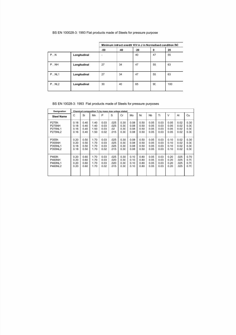
7/22/2019 CSWIP 3.2 LATEST WIS10-Mar-2011
http://slidepdf.com/reader/full/cswip-32-latest-wis10-mar-2011 295/303
BS EN 100028-3: 1993 Flat products made of Steels for pressure purpose
BS EN 10028-3: 1993 Flat products made of Steels for pressure purposes
P…N Longitudinal
P…NH
P…NL1
P…NL2
Longitudinal
Longitudinal
Longitudinal
Minimum im act ener KV in J in Normalised condition N
-50 -40 -20 0 20
-
27
27
30
-
34
34
40
40
47
47
65
47
55
55
90
55
63
63
100
Designation Chemical composition % by mass max unless stated
Steel Name
P275NP275NHP275NL1P275NL2
P355NP355NHP355NL1P355NL2
P460NP460NHP460NL1
P460NL2
C
0.180.180.160.16
0.200.200.180.18
0.200.200.20
0.20
Si Mn P S Cr Mo Ni Nb Ti V Al Cu
0.400.400.400.40
0.500.500.500.50
0.600.600.60
0.60
1.401.401.501.50
1.701.701.701.70
1.701.701.70
1.70
0.030.030.030.02
0.030.030.030.02
0.030.030.03
0.02
.025
.025
.02
.015
.025
.025
.025
.015
.025
.020
.020
.015
0.300.300.300.30
0.300.300.300.30
0.300.300.30
0.30
0.080.080.080.08
0.080.080.080.08
0.100.100.10
0.10
0.500.500.500.50
0.500.500.500.50
0.800.800.80
0.80
0.050.050.050.05
0.050.050.050.05
0.050.050.05
0.05
0.030.030.030.03
0.030.030.030.03
0.030.030.03
0.03
0.050.050.050.05
0.100.100.100.10
0.200.200.20
0.20
0.020.020.020.02
0.020.020.020.02
.025
.025
.025
.025
0.300.300.300.30
0.300.300.300.30
0.700.700.70
0.70

7/22/2019 CSWIP 3.2 LATEST WIS10-Mar-2011
http://slidepdf.com/reader/full/cswip-32-latest-wis10-mar-2011 296/303
1 1
2 2
3 3
4 4
5 5
6 6
7 7
8 8
9 9
1 0
1 0
1 1
1 1
1 2
1 2
A
A
B
B
C
C
D
D
E
E
F
F
G
G
H
H
1 : 2
S I Z E
A 1
T I T L E
S C A L E
D W G N O
2 1 6 6
- C 0 0 1 B
A S S E M B L Y B R A C K E T S
H E E T
O F
1
A R E V
1
1 3 / 0 1 / 2 0 0 9
p d e
C A
M B R I D G E
C B 2 1 - 6 A L
-
U K
T H I S
D O C U M E N T
M A Y
N O T
B E
C O P I E D
O R
D
I S C L O S E D
T O
A
T H I R D
P A R T Y
W I T H O U T
T H E
W R I T T E N
C O N S E N T
O F
T W I
L t d .
G R E A T
A B I N G T O N
T W I
L t d
G R A N T A
P A R K
D R A W N
C H E C K E D
A M F G
A
R O V E D
N 5
` `
0 . 5
0
`
N 7
1 5
`
A N G U L A R
D I M E N S I O N S
2
D E C I M A L
P L A C E S
0 . 0
5
O T H E R
D I M E N S I O N S
G E N E R A L
T O L E R A N C E S
0 . 1
0
1
D E C I M A L
P L A C E
D I
M E N S
I O N S
I N
M I L I M E T R E S
3
A N G L E
R D
S Y M B O L S
T O
B S 3 9 3 9
G E O M E T R I C
T O L E R A N C E
C
2 0 0 9
P a r t s L i s t
D E S C R I P T I O N
P A R T N U M B E R
Q T Y
I T E M
3 5 0 x 3 5 0 x 1 2
2 1 6 6 - C
0 1 0
1
1
1 5 0 x 7 5 x 1 2
2 1 6 6 - C
0 1 1
2
2
2 5 0 x 1 5 0 x 1 2
2 1 6 6 - C
0 1 2
2
3
3 0 0 x 1 2 5 x 1 2
2 1 6 6 - C
0 1 3
2
4
2 0 0 x 1 5 0 x 1 2
2 1 6 6 - C
0 1 4
1
5
6 0 O D 5 W A L L 8 0 L O N G
2 1 6 6 - C
0 1 5
2
6
2 5
1 3
2 5
2 5
3 0 0
1 2 5 1 2 5
1 5 0
1 5 0
2 5 0
1 5 0
7 5
1 5 0
7 5
8 0
8 0
7 5
2 0 0
1 0 0
n 6 0
5 0 n
2 0 x
4 5 ~
3 5 0
3 5 0
M A T E R I A L
: -
1 2
T
H I C K
C A R B O N
S T E E L
N O T E
:
-
A L L
B U T T
W E L D S
T O
B E
F U L
L
P E N E T R A T I O N
F R O M
O N E
S
I D E
1 3 5
1 3 5
z 6
1 3 5
1 3 5
1 1 1
z 6
1 3 5
z 6
1 3 5
z 6
1 3 5
a 6
1 3 5
z 6
1 3 5
z 6
1 3 5
z 8
1 1 1
1 4 1
4
3
3
1
2
5
6
6
2
4

7/22/2019 CSWIP 3.2 LATEST WIS10-Mar-2011
http://slidepdf.com/reader/full/cswip-32-latest-wis10-mar-2011 297/303
S
E C T I O N
A -
A
1
2
3
4
5
6
7
8
A
A
B
B
C
C
D
D
E
E
F
F
C A M B R I D G E
C B 2 1 - 6 A L
-
U K
p d e
G R E A T
A B I N G T O N
T H E
W R I T T E N
C O N S E N T
O F
T W I
L t d .
T W I
L t d
G R A N T A
P A R K
D I S C L O S E D
T O
A
T H I R D
P A R T Y
W I T H O U T
T H I S
D O C U M E N T
M A Y
N O T
B E
C O P I E D
O R
0 6 / 0 2 / 2 0 0
A 2
1 : 2 0
T E S 2 1 1 - A 0 0 1
V E S S E L F A B R I C A T I O N
1
1
A
O F
S H E E T
D W G N O
S I Z E
S C A L E
T I T L E
A P P R O V E D
M F G
Q A
C H E C K E D
D R A W N
R E V
D I M
E N S I O N S
I N
M I L L I M E T R E S
3
2
D E C I M A L
P L A C E S
G E O M E T R I C
T O L E R A N C E
S Y M B O L S
T O
B S 3 9 3 9
A N G L E
R D
C
2 0 0
8
`
1
D E C I M A L
P L A C E
N 7
0
. 5 0
O T H E R
D I M E N S I O N S
N 5
0
. 1 0
1 5
` ` `
0
. 0
5
G E N E R A L
T O L E R A N C E S
A N G U L A R
D I M E N S I O N S
A A
1
2
3
4
5
6
7
8
9
1 0
1 1
4 0
0
4 0 0
4 0 0 0
n
5 7 0
2 0 0 0
9 0 0
2 4 0 0 Ø
2 5 °
1 2 0 0
8 0 0
1 1 5 0
1 0 0
2 0
1 0 0
1 0
1 5 2 0
2 0
2 4 0 0
2 3 5 0
5 0
3 0 °
5 0
5 0
7 0 0
1 5 0
5 0 0 Ø 2
5
6 0 0
Ø
7 0 0
Ø
1 4 0 0
1 4 0 0
C A S T S / S
I N S P E C T I O N
C A S T S / S
I N L E T V A L V E
C A S T S / S
O U T L E T V A L V E
N O T E
: -
S H E L L
1 5 T
H I C K
D I S H
E N D S
P R E - F A B
M A T E R I A L
: -
M A I N
V E S S E L L
3 1 6 L
1 8 % / 8 % .
S U P P O R T
F R A M E
C A R B O N
S T E E
L
W E L D
P R O C E D U R E
U S
E D
: -
H E A L T H
A N D
S A F E T Y
C O N C E R N S
: -
B U I L D
S E Q U E N C E
: -
C O N S U M A B L E S
: -
4 5 °
2 9 8 0
1 3 6
1 3 6
z 4
1 3 5
z
5
1 4 1
1 4 1
1 3 5
z 4
W P S
z 6
1 3 5

7/22/2019 CSWIP 3.2 LATEST WIS10-Mar-2011
http://slidepdf.com/reader/full/cswip-32-latest-wis10-mar-2011 298/303
QUALITY PLAN
PLAN No. 2345/QP/001 Sheet 1 of 4
PROJECT TITLE SHOP FABRICATION of a PRESSURE VESSEL
COMPANY ORDER No. 2345
CLIENT
CLIENT ORDER No.
ADDITIONAL INFORMATION
CLIENT SPECIFICATIONS
Technical Specification: Pressure Vessel Code xxxxxx
MATERIALS
Carbon Steel Plate to xxxxx
C-Mn Steel Fittings to xxxx
C-Mn Steel Flanges to xxxx
REVISION STATUS Rev. No. Date Description of change
0 xx.xx.xx N/A
INSPECTION CODES APPROVAL STAMPS
Company Client
A1 = 100% ACTUAL INSPECTION OR TEST
A2 = RANDOM INSPECTION OR TEST
W1 = 100% WITNESS INSPECTION /TEST
W2 = RANDOM WITNESS INSPECTION /TEST
S = IN PROGRESS INSPECTION (PATROL)
H = MANDATORY HOLD POINT
R1 = 100% EXAMINATION OF DOCUMENTS 3rd PartyR2 = SAMPLE EXAM. OF DOCS. (CLIENT)
AP = SUBMIT DOCUMENTS FOR APPROVAL
IN = SUBMIT FOR INFORMATION
N = NOTIFY CLIENT
N/A = NOT APPLICABLE
DATE
PLAN COMPLIANCE NAME & TITLE SIGNATURE
FOR COMPANY
FOR CLIENT

7/22/2019 CSWIP 3.2 LATEST WIS10-Mar-2011
http://slidepdf.com/reader/full/cswip-32-latest-wis10-mar-2011 299/303
2345/QP/001
Op. OPERATION DETAILS REFERENCE RESPONSIBILITY
No. DOCUMENTS Company 3rd Party Cli
A DESIGN
1 Review Contract & design requirements Client P.O., PV Code Project Engineer R1
2 Prepare manufacturing drawings Client Spec.; PV Code Project Engineer R1. AP R1
B PRELIMINARY MANUFACTURING OPERATIONS
1 Place orders for materials & sub-contracted operations QA Poc. xx Purchasing A1
2 Qualify Welding Procedures & welders QA Poc. xx Welding Engineer A1, R1
3 Prepare WPS's & submit for approval QA Poc. xx Welding Engineer R1, AP R1
4 Prepare welder qualification register QA Poc. xx Welding Engineer R1
5 Verify NDE Operator qualifications QA Poc. xx Quality Manager R1
6 Issue Contract-specific documents to controlled distribution QA Poc. xx Projects A1
C MATERIAL CONTROL
1 Inspect materials for quantity, dimensions & damage QA Proc xx & Delivery Material Controller A1
2 Check material identitification & test certificates QA Proc xx, Purchase Inspector R1
3 Check dimensions of heads H1 & H2 Drawing Inspector R1
D FABRICATION & NDE
1 Cut plate for shell, wrapper & saddles; maintain identities Drawings, head dimensi Material Controller A1
QA Poc. xx Inspector S
2 Edge-prepare plates for welding WPS's, Drawings Plater A1
3 Roll shell plates & wrapper plates Drawings Inspector S
Inspector S
4 Weld shell longitudinal seams (T1, T2, T3) WPS Welder/Inspector S
5 Visually inspect welds; MPI & radiograph welds NDE Proc. xxx & XXX Inspector A1
Revision No. 0
INSPECTION / TEST CODE

7/22/2019 CSWIP 3.2 LATEST WIS10-Mar-2011
http://slidepdf.com/reader/full/cswip-32-latest-wis10-mar-2011 300/303
2345/QP/001
Op. OPERATION DETAILS REFERENCE RESPONSIBILITY
No. DOCUMENTS Company 3rd Party Cli
6 Fit & weld N1 to H1, N2 to T1 and N3 to T3 WPS, Drawing Welder/Inspector A1/S
7 Visually inspect & MPI welds NDE Proc. XXX Inspector A1
8 Fit & weld circ. Seams for tiers T1, T2 & T3
9 Visually inspect welds,; MPI & radiograph welds NDE Proc. Xxx & XXX Inspector A1
10 Fit & weld N1-H1 to T1-T2-T3 WPS Welder/Inspector A1/S
11 Visually inspect welds,; MPI & radiograph welds NDE Proc. Xxx & XXX Inspector A1
12 Fit & weld H2 to H1-T1-T2-T3 WPS Welder/Inspector A1/S
13 Visually inspect welds,; MPI & radiograph welds NDE Proc. Xxx & XXX Inspector A1
14 Fit & weld wrapper plates W1 & W2 to shell WPS Welder/Inspector A1/S
15 Visually inspect welds; MPI welds NDE Proc. XXX Inspector A1
16 Fit & weld saddles S1 & S2 to wrapper plates W1 & W2 WPS Welder/Inspector A1/S
17 Visually inspect welds; MPI welds NDE Proc. XXX Inspector A1
E DIMENSIONAL SURVEY
1 Dimensionally inspect finished vessel QC Proc xx, Drawings, Inspector A1
F POST WELD HEAT TREATMENT
1 Prepare vessel & implement PWHT operation QC Proc xxxx Furnace Controller A1
Inspector S
G PRESSURE TESTING
1 Prepare vessel & implement pressure test QC Proc xxxx Inspector A1
2 Dry & clean vessel; visually inspect & dimensionally survey QC Proc xxxx Inspector A1
Revision No. 0
INSPECTION /TEST CODE

7/22/2019 CSWIP 3.2 LATEST WIS10-Mar-2011
http://slidepdf.com/reader/full/cswip-32-latest-wis10-mar-2011 301/303
2345/QP/001
Op. OPERATION DETAILS REFERENCE RESPONSIBILITY
No. DOCUMENTS Company 3rd Party Cli
H COATING (by sub-contractor)
1 Prepare vessel & apply coating QC Proc xxxx Sub-Contractor A1
Painting Inspector S
2 Inspect finished coating QC Proc xxxx
I VESSEL NAME PLATE
1 Manufacture & attach vessel nameplate; make record Drawing, Code Inspector A1
J DESPATCH VESSEL TO SITE
1 Prepare documenation for vessel transport and arrange QA Proc xxxx Inspector R1 N
for Client realease note
2 Despatch vessel QA Proc xxxx Despatcher A1
I MANUFACTURING RECORDS
1 Collate records for archive; transmit copies to Client QA Proc xxxx Doc. Controller H H
Revision No. 0
INSPECTION / TEST CODE

7/22/2019 CSWIP 3.2 LATEST WIS10-Mar-2011
http://slidepdf.com/reader/full/cswip-32-latest-wis10-mar-2011 302/303
Section 24
Further Reading

7/22/2019 CSWIP 3.2 LATEST WIS10-Mar-2011
http://slidepdf.com/reader/full/cswip-32-latest-wis10-mar-2011 303/303
Rev 1 January 2011Further Reading
C i ht TWI Ltd 2011