ct3109 : structural mechanics...
TRANSCRIPT

Ir J.W. Welleman page 1
CT3109 : Structural Mechanics 4
� 17-19 Influence Lines • Introduction
• Maxwell
• Static determinate structures
• Qualitative
• Quantitative
• Static indeterminate structures
• Qualitative
• Quantitative
• Special Applications
CIE3109 LECTURE 17
Ir J.W. Welleman page 2
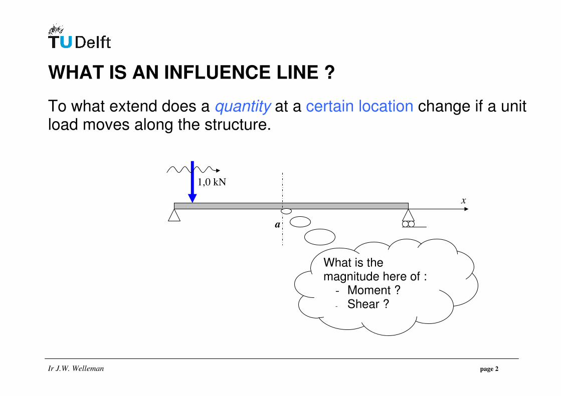
WHAT IS AN INFLUENCE LINE ?
To what extend does a quantity at a certain location change if a unit load moves along the structure.
What is the magnitude here of :
- Moment ? - Shear ?
1,0 kN
x
a

Ir J.W. Welleman page 3
DEFINITION
An influence line gy is a graphical representation of the influence of a unit load at position x on the magnitude of a quantity at position a.
Relevant Quantities ???
• Moment
• Shear force
• Reactions
• displacement / rotation required tool : Maxwell’s Reciprocal Theorem
FORCE QUANTITIES
DISPLACEMENT QUANTITIES

Ir J.W. Welleman page 4
WHY INFLUENCE LINES ?
Influence Lines are important to find the most unfavourable position of the loads for a certain quantity. Often used for moving loads on bridges and so on.
But also …..
Influence Lines can be used to find the most unfavourable position of the static distributed loads in structures like buildings.

Ir J.W. Welleman page 5
SO …..
With an influence line we can directly read for a certain position inside the structure where we have to put the load in order to obtain the maximum value for the observed quantity.
FIXED POSITION
VARIABLE
Ir J.W. Welleman page 6
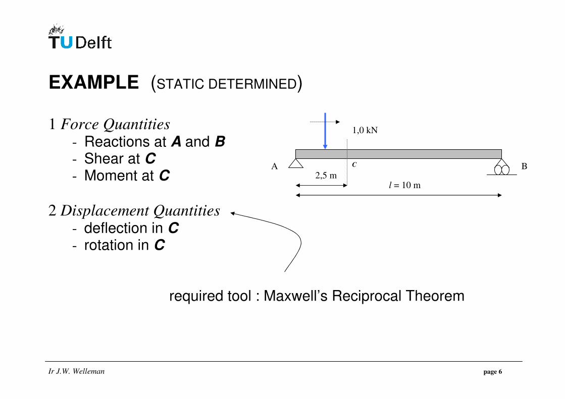
EXAMPLE (STATIC DETERMINED)
1 Force Quantities - Reactions at A and B - Shear at C - Moment at C
2 Displacement Quantities - deflection in C - rotation in C required tool : Maxwell’s Reciprocal Theorem
1,0 kN
l = 10 m
B A C
2,5 m
Ir J.W. Welleman page 7
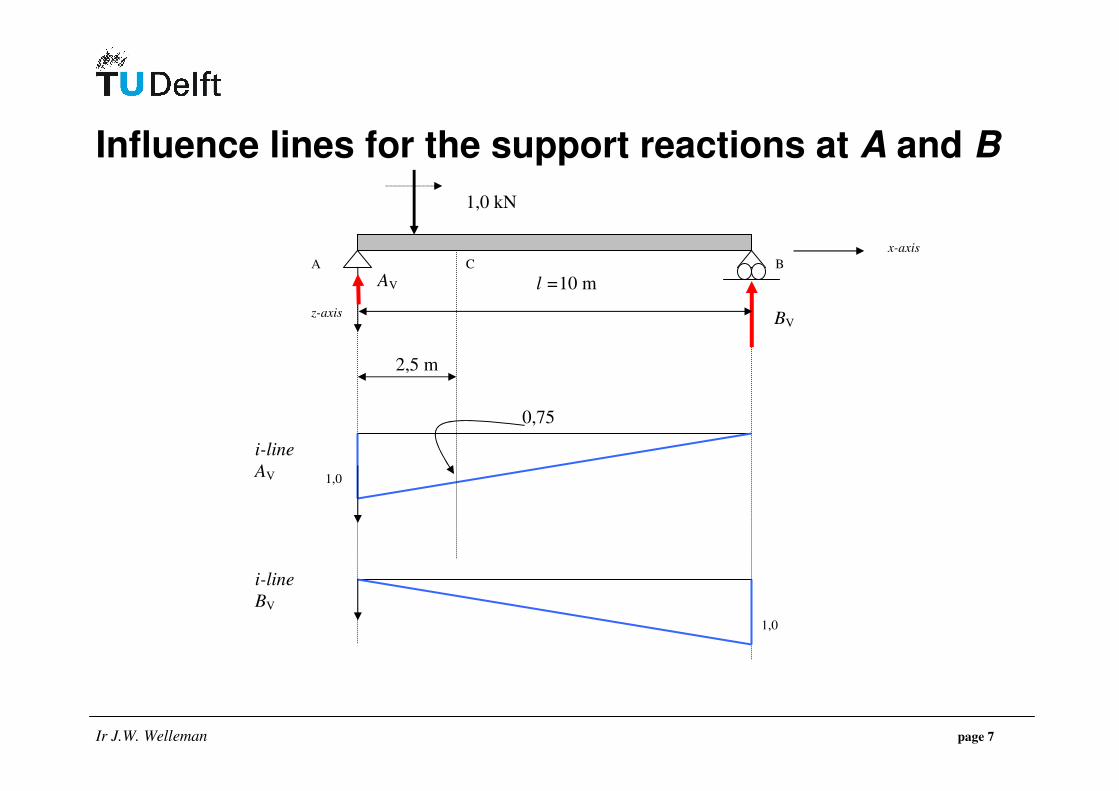
Influence lines for the support reactions at A and B
1,0 kN
l =10 m
z-axis
x-axis
1,0
1,0
i-line
AV
i-line
BV
0,75
2,5 m
A B C
BV
AV
Ir J.W. Welleman page 8
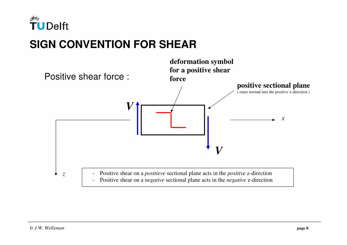
SIGN CONVENTION FOR SHEAR Positive shear force :
V
x
z
V
- Positive shear on a positieve sectional plane acts in the positive z-direction
- Positive shear on a negative sectional plane acts in the negative z-direction
positive sectional plane ( outer normal into the positive x-direction )
deformation symbol
for a positive shear
force
Ir J.W. Welleman page 9
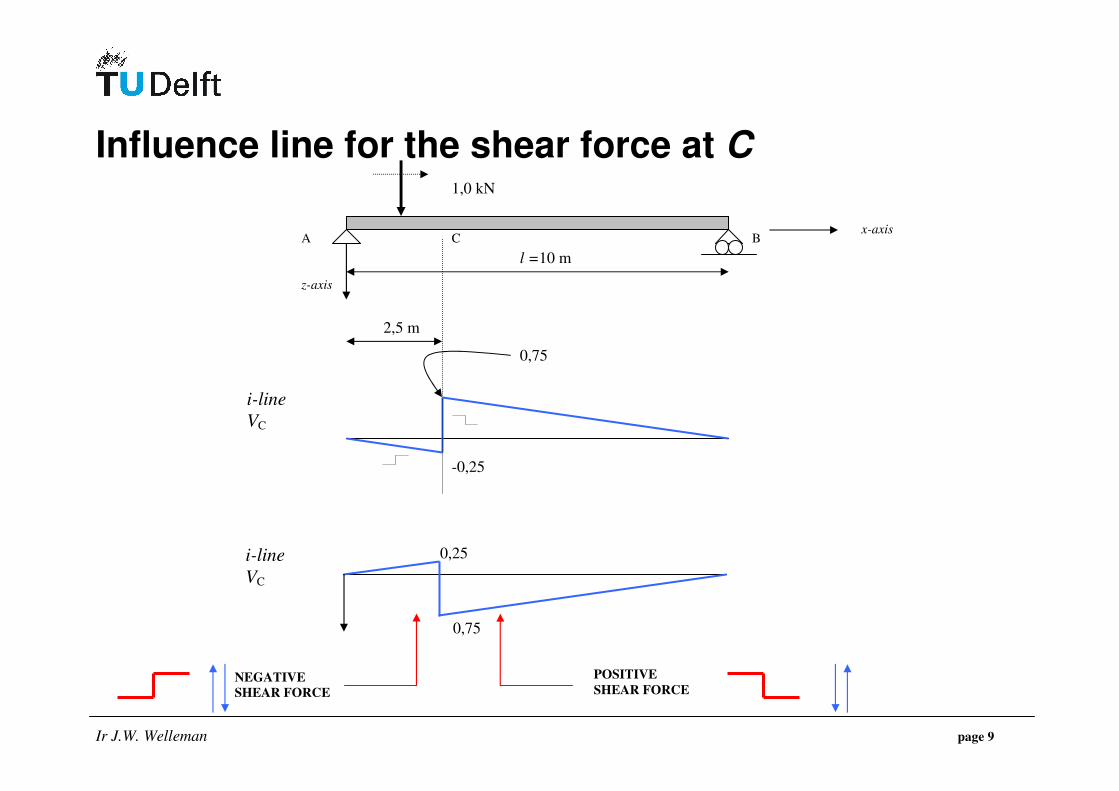
Influence line for the shear force at C
NEGATIVE
SHEAR FORCE
POSITIVE
SHEAR FORCE
1,0 kN
l =10 m
z-axis
x-axis
i-line
VC
0,75
2,5 m
-0,25
B A C
i-line
VC
0,75
0,25

Ir J.W. Welleman page 10
WHAT ABOUT THE SIGNS ?? Note : Take care of these signs, see book page 83 !!!
1,0 kN
l =10 m
2,5(-) m
0,75 kN
0,25 kN
1,0 kN
0,75 kN 0,25 kN
B A
Just before the load passes C, the shear is –0,25, after
passage the shear jumps to + 0,75 !!
Ir J.W. Welleman page 11
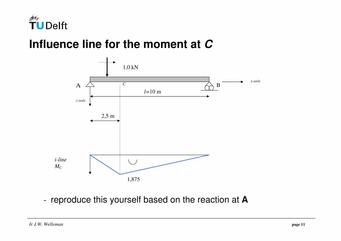
Influence line for the moment at C
- reproduce this yourself based on the reaction at A
1,0 kN
l=10 m
z-axis
x-axis
i-line
MC
2,5 m
1,875
B A C
Ir J.W. Welleman page 12
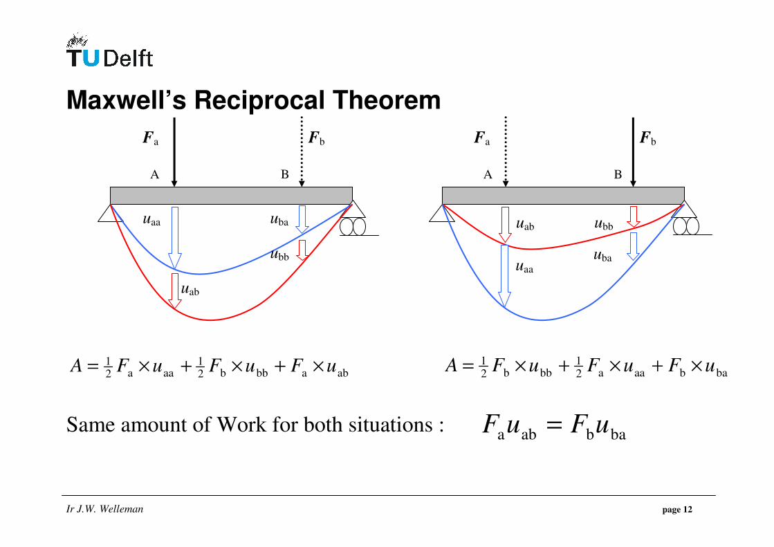
Maxwell’s Reciprocal Theorem
ababbb21
aaa21 uFuFuFA ×+×+×=
babaaa21
bbb21 uFuFuFA ×+×+×=
Same amount of Work for both situations :
uaa uba
Fa Fb
ubb
uab
uaa
uba
Fa Fb
ubb uab
A B A B
bababa uFuF =
Ir J.W. Welleman page 13
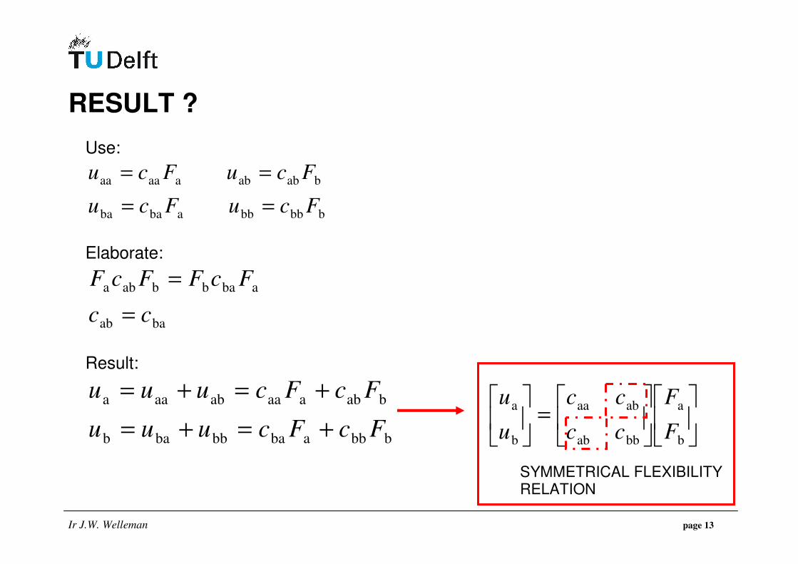
RESULT ?
Use:
bbbbbababa
bababaaaaa
FcuFcu
FcuFcu
==
==
Elaborate:
baab
ababbaba
cc
FcFFcF
=
=
Result:
bbbababbbab
babaaaabaaa
FcFcuuu
FcFcuuu
+=+=
+=+=
=
b
a
bbab
abaa
b
a
F
F
cc
cc
u
u
SYMMETRICAL FLEXIBILITY RELATION

Ir J.W. Welleman page 14
Influence line for the deflection at C Check a number of points :
• Deflection at C t.g.v. 1,0 kN in C : wcc
• Deflection at C t.g.v. 1,0 kN in D : wcd = wdc
• Deflection at C t.g.v. 1,0 kN in E : wce = wec
CONCLUSION ???
1,0 kN
4×2,5 m
B A C D E
1,0 kN 1,0 kN
wcc wdc
wec
Apply
Maxwell !
Ir J.W. Welleman page 15
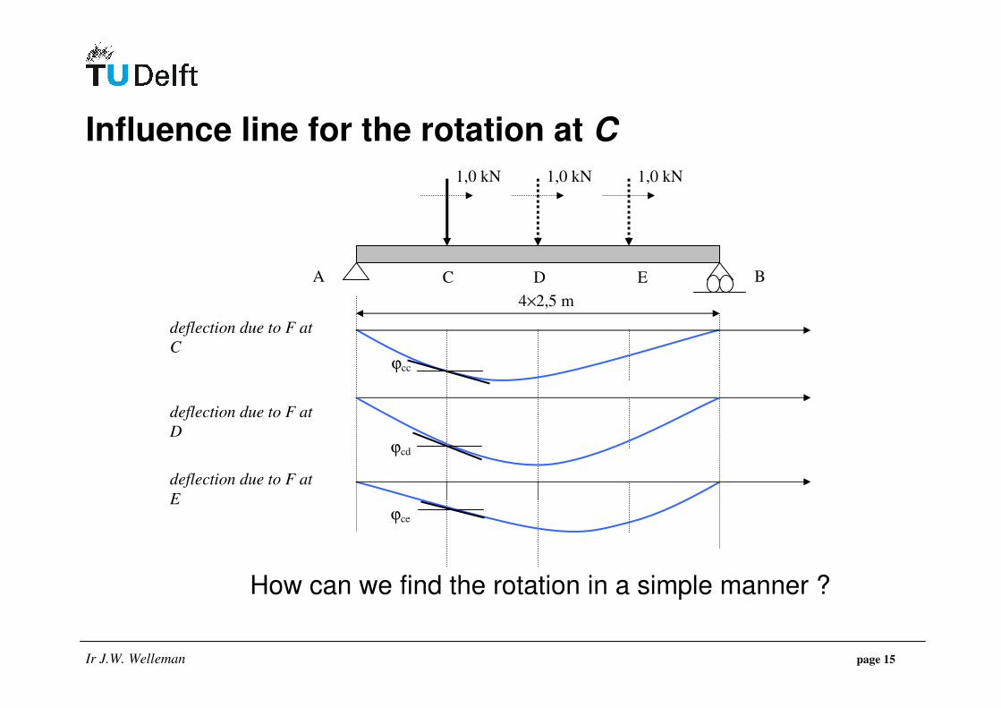
Influence line for the rotation at C
How can we find the rotation in a simple manner ?
1,0 kN
4×2,5 m
B A C D E
deflection due to F at
C
1,0 kN 1,0 kN
deflection due to F at
D
deflection due to F at
E
ϕcc
ϕcd
ϕce
Ir J.W. Welleman page 16
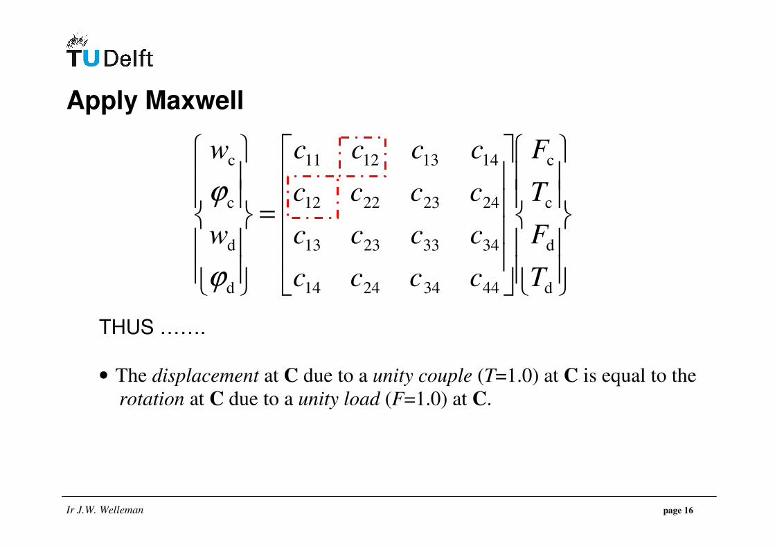
Apply Maxwell
=
d
d
c
c
44342414
34332313
24232212
14131211
d
d
c
c
T
F
T
F
cccc
cccc
cccc
cccc
w
w
ϕ
ϕ
THUS …….
• The displacement at C due to a unity couple (T=1.0) at C is equal to the
rotation at C due to a unity load (F=1.0) at C.
Ir J.W. Welleman page 17
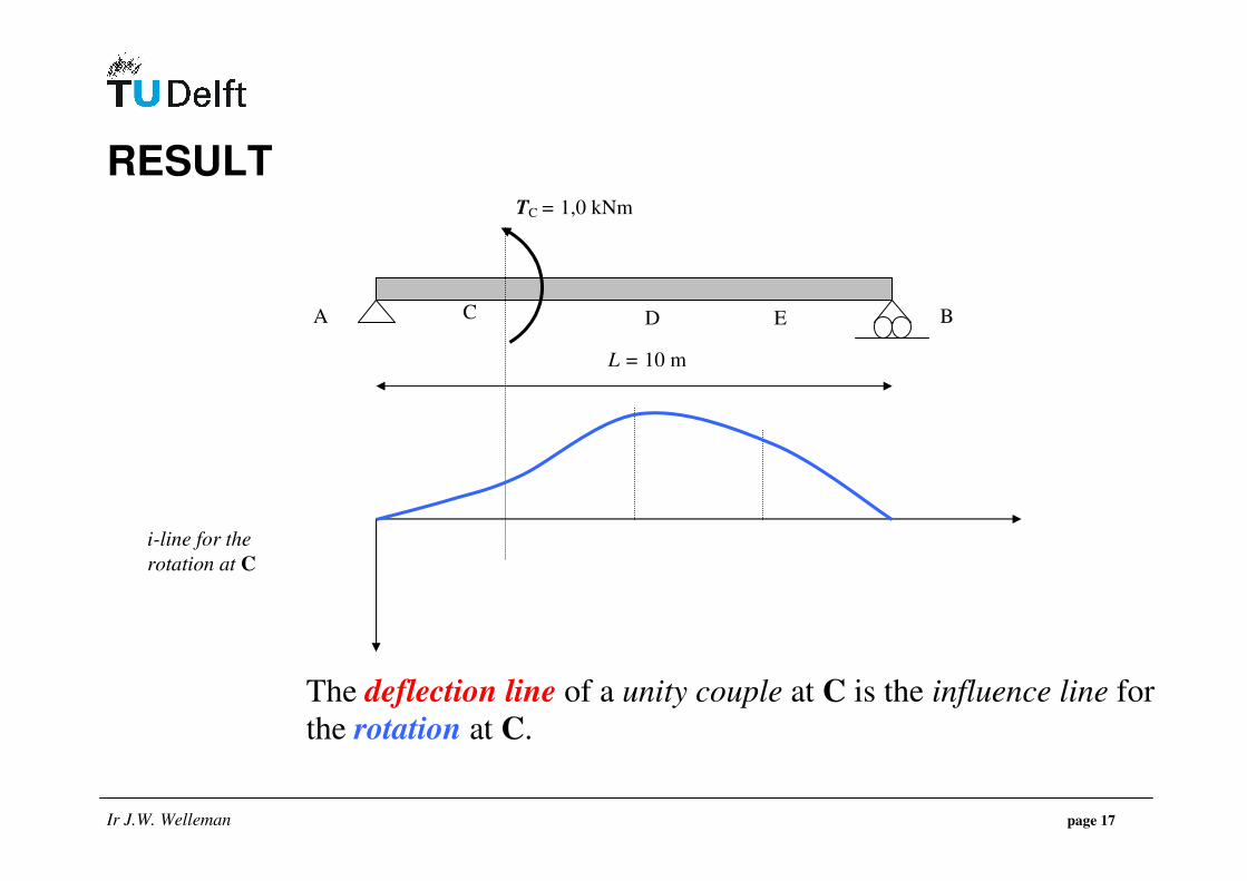
RESULT The deflection line of a unity couple at C is the influence line for
the rotation at C.
L = 10 m
B A C D E
i-line for the
rotation at C
TC = 1,0 kNm
Ir J.W. Welleman page 18
SUMMARY : DISPLACEMENT QUANTITIES
• Influence line for the deflection at a certain point : o Put a unity load at the point of interest. o The deflection line due to the unity load is the required
influence line for the deflection at the point of observation.
• Influence line for the rotation at a certain point : o Put a unity couple at the point of interest. o The deflection line due to the couple is the required
influence line for the roation at the point of observation.
• Please find us a method as easy for the Influence Lines of Force Quantities ….
Ir J.W. Welleman page 19
ELEGANT WAY TO FIND THE INFLUENCE LINES OF FORCE QUANTITIES
Müller-Breslau principle Release the degree of freedom which belongs to the observed force quantity (e.g. remove a suppport or add a hinge) and generate Negative Virtual Work with the observed force quantity by imposing a virtual unit displacement. The displaced structure (mechanism) is the required influence line.
Ir J.W. Welleman page 20
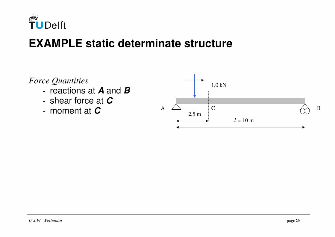
EXAMPLE static determinate structure
Force Quantities
- reactions at A and B - shear force at C - moment at C
1,0 kN
l = 10 m
B A C 2,5 m

Ir J.W. Welleman page 21
REACTIONS
+
+
1,0 kN
l = 10 m
B A C 2,5 m
B
AV
δ w =1,0 i-line for
AV
A
BV
δ w =1,0
i-line for
BV
x-axis
z-axis

Ir J.W. Welleman page 22
MOMENT AT C
1,0 kN
l =10 m
z-axis
x-axis
i-line for
MC
2,5 m
B A C
S MC MC
δ w
δ θ =1,0
875,1
0,15,75,2
=
=+=
w
ww
δ
δδδθ

Ir J.W. Welleman page 23
SHEAR FORCE AT C
1,0 kN
l = 10 m
z-as
x-as
i-line for
VC
2,5 m
B A C
“shear hinge”
VC
VC
δ w=1,0 +

Ir J.W. Welleman page 24
SUMMARY
• Influence lines for the deflection at a certain point :
o Put a unit load at the point of interest. o The deflection line is the influence line for the deflection at the observed point.
• Influence line for the rotation at a certain point :
o Put a unit couple at the point of interest. o The deflection line is the inflence line for the rotation at the observed point.
• Influence line for force quantities, apply Müller-Breslau :
o Release the degree of freedom which belongs to the observed force quantity (e.g. remove a suppport or add a hinge) and generate Negative Virtual Work with the observed force quantity by imposing a virtual unit displacement or unit rotation.
o The position of the mechanism is the required influence line.