ctc io techoloies co. - ctcu.com.tw · pdf fileoptical fiber installation, maintenance, field...
TRANSCRIPT

Pulse input
Fiber
Reflected pulse
System control analysis and I/O
Photo detector
OTDR laser diode
Pulse generator
Specifications & design are subject to change without prior notice. Please visit CTC Union website for more details.
w w w.c tcu.com CTC UNION TECHNOLOGIES CO., LTD. 13-1 OTDR-30A
OTDR-30A
The OTDR-30A is an OTDR (Optical Time Domain Reflectometer) based optical fault locator and analysis tool for optical fiber networks. The OTDR-30A supports Single mode 1310nm, 1550nm with Dynamic Range 28/26dB.The OTDR features a light, compact, hand-held design with an intelligent user interface that is easy and quick to use. The color LCD display with bright backlight makes testing work more comfortable and convenient, whether during daylight or in low light conditions. As a fault locating and analyzing tool, the OTDR-30A is much more economical than traditional OTDRs. In addition to its 1000 plus internal curve storage, the OTDR-30A can save and transfer the measurement curves data to a PC via serial or USB port for further analysis or printing with Window based "Trace Manager" software. When set in auto measurement mode, the user can activate the measurement operations easily by the push of only one button. The OTDR-30A is ideal for optical fiber installation, maintenance, field construction, and other on-site fault-location analysis.
Features
Specifications
• Ideal for LAN/WAN certification & trouble-shooting• Fiber length/splice/fiber-end detection• Handheld & lightweight• Overall fiber applications:• SM: 1310/1550nm(with filter), up to 28dB• Quick start: <5 seconds• Hotkeys: Easiest operation in the world, push-and-test• High precision measurement, 1000 test records storage
Selectable Range (Km) 0.3,1.3, 2.5, 5, 10, 20, 40, 80, 120Pulse Width 5ns, 12ns, 30ns, 100ns, 275ns, 1µs, 2.5µs, 10µsAveraging Time 15s, 30s, 1min, 2min, 3min Distance Measure Accuracy ±(1m + 5×10⁻⁵×distance + sampling space)
Attenuation Detect Accuracy ±0.05 dB/ dB
Reflection Detect Accuracy ±4 dB
Data Storage 1000 records Connectivity USB/RS-232
• USB/RS-232 data interface• Bellcore file format (.sor)• PC software for traces batch editing & flexible printing• Multilanguage: EN/DE/FR/ES/PT/RU/KR/CN• 8 hrs continuous operation/20 hrs standby• Dust-shock proof (2m drop test)
Connector FC/PC (Interchangeable SC, ST) Power Supply NiMH Battery / AC Adapter Battery Life 8 hours continuous operation; 20 hours standby
(on one charge) Operating Temperature 0 ~ 50°C Storage Temperature -20 ~ 70°C Relative Humidity 0 ~ 95% (non-condensing) Weight 1kg (2.2 lbs) Dimensions 100 x 196 x 60mm (D x W x H)
Single Mode Optical Time Domain Reflectometer
An OTDR component setup
Ordering InformationModel Name DescriptionOTDR-30A 28/26dB, 1310/1550nm, Single mode OTDR tester
Model Name Wavelength (±20nm) Dynamic Range Event DeadZone(m) Attenuation DeadZone(m)
OTDR-30A 1310/1550 28/26dB 1.8 8
Visible Fault Locator (Only available with Type B/N and C/N)
Output Power (dBm) ≥ -3
Max Measurement Range 5 Km
Tester - Optical fiber tester
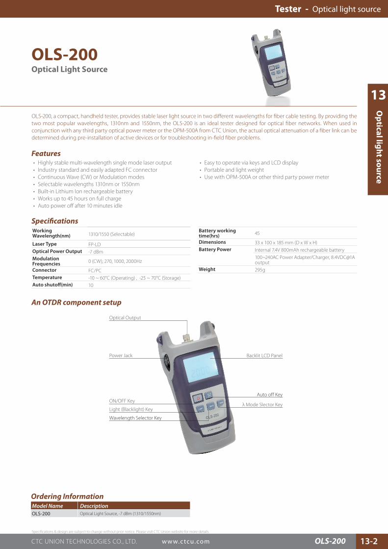
ON/OFF Key
Light (Blacklight) Key
Wavelength Selector Key
Power Jack Backlit LCD Panel
Auto off Key
λ Mode Slector Key
Optical Output
13
Specifications & design are subject to change without prior notice. Please visit CTC Union website for more details.
w w w.c tcu.comCTC UNION TECHNOLOGIES CO., LTD. 13-2OLS-200
Op
tical ligh
t sou
rce
OLS-200
OLS-200, a compact, handheld tester, provides stable laser light source in two different wavelengths for fiber cable testing. By providing the two most popular wavelengths, 1310nm and 1550nm, the OLS-200 is an ideal tester designed for optical fiber networks. When used in conjunction with any third party optical power meter or the OPM-500A from CTC Union, the actual optical attenuation of a fiber link can be determined during pre-installation of active devices or for troubleshooting in-field fiber problems.
Features
Specifications
• Highly stable multi-wavelength single mode laser output • Industry standard and easily adapted FC connector • Continuous Wave (CW) or Modulation modes • Selectable wavelengths 1310nm or 1550nm • Built-in Lithium Ion rechargeable battery • Works up to 45 hours on full charge • Auto power off after 10 minutes idle
Working Wavelength(nm) 1310/1550 (Selectable)
Laser Type FP-LDOptical Power Output -7 dBmModulation Frequencies 0 (CW), 270, 1000, 2000Hz
Connector FC/PCTemperature -10 ~ 60°C (Operating) , -25 ~ 70°C (Storage)Auto shutoff(min) 10
• Easy to operate via keys and LCD display • Portable and light weight • Use with OPM-500A or other third party power meter
Battery working time(hrs) 45
Dimensions 33 x 100 x 185 mm (D x W x H)Battery Power Internal 7.4V 800mAh rechargeable battery
100~240AC Power Adapter/Charger, 8.4VDC@1A output
Weight 295g
Optical Light Source
An OTDR component setup
Tester - Optical light source
Ordering InformationModel Name DescriptionOLS-200 Optical Light Source, -7 dBm (1310/1550nm)
Specifications & design are subject to change without prior notice. Please visit CTC Union website for more details.
w w w.c tcu.com CTC UNION TECHNOLOGIES CO., LTD. 13-3
Auto shutoff time(min) 10
Battery working time(hrs) 48
Dimensions 33 x 82 x 172 mm (D x W x H)Power nternal 7.4V 800mAh rechargeable battery
100~240AC Power Adapter/Charger, 8.4VDC@1A outputWeight 295g
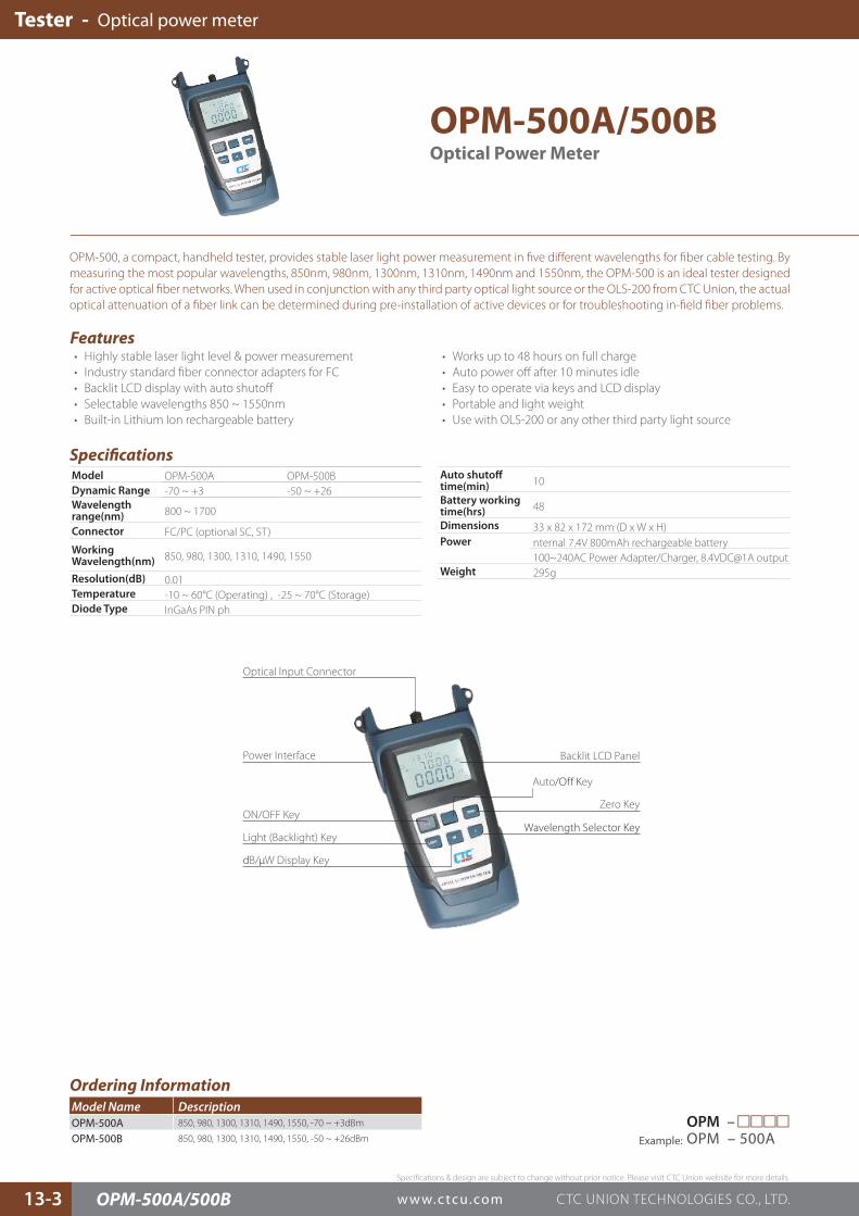
OPM-500A/500B
OPM-500, a compact, handheld tester, provides stable laser light power measurement in five different wavelengths for fiber cable testing. By measuring the most popular wavelengths, 850nm, 980nm, 1300nm, 1310nm, 1490nm and 1550nm, the OPM-500 is an ideal tester designed for active optical fiber networks. When used in conjunction with any third party optical light source or the OLS-200 from CTC Union, the actual optical attenuation of a fiber link can be determined during pre-installation of active devices or for troubleshooting in-field fiber problems.
Features
Specifications
• Highly stable laser light level & power measurement • Industry standard fiber connector adapters for FC • Backlit LCD display with auto shutoff • Selectable wavelengths 850 ~ 1550nm • Built-in Lithium Ion rechargeable battery
• Works up to 48 hours on full charge • Auto power off after 10 minutes idle • Easy to operate via keys and LCD display • Portable and light weight • Use with OLS-200 or any other third party light source
Optical Power Meter
Model OPM-500A OPM-500BDynamic Range -70 ~ +3 -50 ~ +26Wavelength range(nm) 800 ~ 1700
Connector FC/PC (optional SC, ST)
Working Wavelength(nm) 850, 980, 1300, 1310, 1490, 1550
Resolution(dB) 0.01Temperature -10 ~ 60°C (Operating) , -25 ~ 70°C (Storage)Diode Type InGaAs PIN ph
Tester - Optical power meter
OPM-500A/500B
Ordering InformationModel Name DescriptionOPM-500A 850, 980, 1300, 1310, 1490, 1550, -70 ~ +3dBm
OPM-500B 850, 980, 1300, 1310, 1490, 1550, -50 ~ +26dBm
ON/OFF Key
Light (Backlight) Key
dB/μW Display Key
Power Interface Backlit LCD Panel
Wavelength Selector Key
Optical Input Connector
Zero Key
Auto/Off Key
OPM –□□□□Example: OPM – 500A

13
Specifications & design are subject to change without prior notice. Please visit CTC Union website for more details.
w w w.c tcu.comCTC UNION TECHNOLOGIES CO., LTD. 13-4
E1 BER
T
Error Rate Test (BERT Test)
BERT Patterns• 511, 2047, 2E15-1, 2E15-1 (reverse), 2E20-1,
2E20-1 (reverse), QRSS, 2E23-1, 2E23-1 (inverted), all 1, all 0, alternate, 1100, 3 IN 24, 1 IN 16, 1 IN 8, 1 IN 4, User programmable 1/2/3
BERT Display Format• Error counting, Alarm counting, ITU G.821, ITU G.826• M.2100, Histogram BERT Transmission Error Rate• Insert one forced error • Fixed error rate of 10-3~10-7 Quality Analysis
• Receiving seconds, Error seconds, Alarm seconds • Error Free seconds, Error rate, Valid seconds • Severely error seconds, G.821 error seconds • G.826 error seconds, Unavailable seconds
Data Port BERT Test• Data rate of the multiple of 64Kbps: N*64Kbps (N=1~36)
Indications LEDs (DTE, DCE, DATA PORT, TD, RD, DCD, RTS, CTS, DTR, DSR, TC, RC XTC)
Power Input AC100 ~ 240V Adapter to DC 9V 2ADimensions 179 x 134 x 68 mm (D x W x H)Weight 0.8kgTemperature 0 ~ 50°C (Operating), -10 ~ 70°C (Storage)Humidity 10 ~ 90% non-condensingMTBF 35,000 hrs
Ordering InformationModel Name DescriptionHCT-BERT/C E1 / Datacom analyzer
HCT-BERT/C
The HCT-BERT/C tester is a compact, color-LCD, graphic-user-interface, single hand E1 Bit error rate tester designed for field use in analysis and maintenance of data communications (V.35, RS530, X.21, RS232) and E1 (2.048Mbps) lines. The HCT-BERT/C performs framed, unframed drop and insert Nx64Kbps, or nx56Kbps data into any time slot. The HCT-BERT/C tester also provides a variety of E1 line statuses, transmission performance testing (BERT) and monitoring. On the E1 line, the HCT-BERT/C may be used as a generator or receiver.
Features
Specifications
• Color LCD display graphic mode• USB port for remote control• Results Report• Supports G.821/826, M.2100 BERT analysis• Sa bits setup and monitor• Internal Memory storage of test result; Direct display on LCD screen
• Print out via Parallel Printer port• Portable for field use• Upgradeable for advanced features• Rechargeable battery with battery low indicator• Supports CRC & BPV performance analysis• Datacom BERT analysis available for V.35, RS-530, X.21 and RS-449 • V.35/ V.24/RS-232/449/530/ X.21
E1/Datacom BER Tester
E1 interface E1 Receiving Interface • Line code: HDB3/AMI• Pulse feature: ITU G.703• Jitter tolerance: ITU G.823 • Input port: BNC (non-balance), RJ45 (balanced)• Input mode: Impedance: 75ohm (unbalanced), 120ohm
(balanced) • Bridging mode: impedance > 1000 ohm E1 Transmission Interface• Line code: HDB3/AMI• Pulse shape: ITU G.703• Pulse amplitude: Nominal 2.37V for BNC 75 ohm Nominal
3.00V for RJ45 120 ohm • Zero amplitude: ±0.1 V at max• Jitter tolerance: ITU G.823• Output port model: BNC (non-balanced), RJ45 (balanced) • Source of clock transmission:
Internal clock: 2.048 MHz ±50ppm, ±100ppm. External clock: receive clock from external clock interface Recovery clock: take clock from received E1 Signal
E1 Frame Format • PCM31, PCM31+CRC, PCM30, PCM30+CRC• Unframed mode, Automatic detection
Other Functions
Color Display Screen: Character/graphic modeTest Results Report• 100 test results max available in storage • Direct display on LCD screen • Print via printer port available Modular Design for Easy Update
Tester - Optical power meter Tester - E1 BERT
HCT-BERT/C
Datacom Port E1 RJ-45 Port E1 BNC Port
External Clock Port
Power SwitchUSB Portfor remote control and file transfer
DB15F Printer PortDC Jack

ContrastControl
LED Indicator
Microphone
I/F Modules
Power Sw.DC Jack
Speaker
Product Overview (Misc.) Product Overview (Connectors)
Lithium lon Battery
PC Card slot
DB9 Remote Ctrlport (DCE)
Interface 2 slot
DB15 printer port(Centronics like)
Interface 1 slot
E1 Terminal ModeMUX feature - E1 BERT & Datacom BERT E1 Bridge Mode
Specifications & design are subject to change without prior notice. Please visit CTC Union website for more details.
w w w.c tcu.com CTC UNION TECHNOLOGIES CO., LTD. 13-5 HCT-7000
Tester - E1 protocol analyzer
Indications System External power, I/F 1 Error, I/F 2 Error, PausedDatacom I/F Module
TD, RD, RTS, CTS, DSR, DTR, DCD, RI, XTC, TC, RC, RL, LL, TM
Power Input AC100~240V adapter to DC 19V/2.9ADimensions 220 x 275 x 65mm (D x W x H)Weight 2.5 KgTemperature 0 ~ 50°C (Operating), -10 ~ 70°C (Storage)Humidity 10 ~ 90% non-condensingCertification CE, FCCMTBF 35,000 hrs
HCT-7000
The HCT-7000, our flagship tester, is a portable, battery powered E1 and data communication tester, designed for a wide range of protocol analysis and BERT (Bit Error Rate Test) at full E1 speeds (2.048Mbps) and is fully suitable for equipment installations, on-line or off-line diagnostics, debugging, and interface development. The HCT-7000 features a backlit Liquid Crystal Display (LCD), push-button switch keyboard, interface lead indicator LEDs, user replaceable data port interface modules and internal rechargeable Li-Ion battery. The unit includes the Basic Interfaces, basic operational firmware, comprehensive User Guide, universal AC power adapter (100~240 VAC) and a sturdy hard shell carry case.
Features
Specifications
• E1, Datacom, Protocol Analyzer and BERT• Protocols: Frame Relay, SS#7, X.25, PPP (Sync.), V5.1. V5.2, ISDN-D,
Sync (BSC), HDLC, SDLC, Async• Dual pluggable interface ports with available modules:• Datacom Module: RS-232C/D (V.24), RS-449 (V.36), RS-530, X.21,
V.35, E1 Module: G.703 E1 (2048K)• Supports Centronics printer & control serial port.• LCD Display: 320x240 graphic (30 lines x 40 characters), with
backlight• Auto Configuration• Menu driven setup
• ASYNC terminal Emulation• File Management• Self Tests and Diagnostics• Display Modes: Full /Half Duplex Data, Frame / Packet and Lead
Status• Error Check: None, Parity, LRC, CRC-16, CRC-CCITT• Capture Buffer: SDRAM• Line Monitor: DTE; DCE; DTE & DCE• Emulation: DTE; DCE; MONITOR only• Counters & Timers: 5 each internal counters and timers• MUX/DEMUX BERT (E1 & Datacom BERT)
Dual Port E1/Datacom Protocol Analyzer and BERT
Ports Data Rate Async (50 ~ 256Kbps); Sync (150 ~ 2048Kbps)
Data Code ASCII, EBCDIC, HEX, IPARS, Transcode, EBCD
Data Length ASYNC Mode: 5,6,7, or 8 bits SYNC Mode: 8 bits
Parity Bit ASYNC Mode:None, Odd, Even, Mark, Space
Stop Bits ASYNC Mode: 1, 2
E1 I/F Module
Signal Present, HDB3, Signal Loss, FAS Loss, AIS, RAI, MRAI, MFAS Loss, CAS Loss, Pattern Loss, Excess Zero, Error