ctc-systems - hearing excellence since 1965 · 4 introduction ctc cross-the-counter systems are a...
TRANSCRIPT

CTC-systemsCross-The-Counter Loop System
Installation Guide

2

3
Contents
Introduction ............................................................................................................... 4Univox CLS-1 loop driver ............................................................................................... 5CTC-120 with glass/wall microphone – installation guide .................................. 6CTC-121 with goose neck microphone – installation guide ................................. 8Troubleshooting ............................................................................................................10Measuring devices ........................................................................................................10 Univox® Listener Univox® FSM, field strength meterSafety and warranty.....................................................................................................11Maintenance and care .................................................................................................11Service .............................................................................................................11Trouble shooting...........................................................................................................11Environment .............................................................................................................11
The Installation Guide is based on the information available at the time of printing and are subject to change without notice.

4
IntroductionCTC Cross-The-Counter systems are a complete system for equipping reception desks and counters with an induction loop. The system consists of a loop driver, a loop pad, a microphone and a wall holder. Installed in a reception desk or counter, the system gives hearing impaired people with hearing aids, the possibility to communicate with the staff behind the desk with greatly enhanced speech perception.
The system is always activated and no special preparations have to be undertaken, neither by the hearing impaired nor by the staff. The only requirement for hard of hearing people is to put their hearing aids in T-position and for the staff to speak normally into the microphone.
All Univox® drivers have a very high output current capability resulting in powerful and secure products fulfilling existing standards, IEC 60118-4.
Thank you for having chosen a Univox® product.
Univox CTC-120Univox CLS-1 loop driver Univox 13V microphone for glass/wall Loop pad, Sign/label with T-symbol 80 x 73 mmWall holder for loop driverPart No: 202040A EU 202040A UK 202040A AM
Univox CTC-121Univox CLS-1 loop driver Univox M-2 goose neck microphoneLoop pad, Sign/label with T-symbol 80 x 73 mmWall holder for loop driverPart No: 202040B EU 202040B UK 202040B AM

5
Loop pad
AVLM5 microphone for glass or wall
M-2 goose neck microphone
Wall holder for loop driver
Univox Compact Loop System CLS-1
Main power indicator Input signal
indicator
Loop current indicatorVolume
controlBass control
Treble control
Power supply
Line Line/ Micro- phone Microphone
sensitivity control
Head-phones
Loop pad Microphone
Room conductor
teleslingaställ in hörapparaten i
t- eller mt-läge
T-symbol label
6
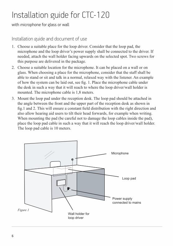
Installation guide for CTC-120 with microphone for glass or wall
Figure 1
Installation guide and document of use1. Choose a suitable place for the loop driver. Consider that the loop pad, the
microphone and the loop driver’s power supply shall be connected to the driver. If needed, attach the wall holder facing upwards on the selected spot. Two screws for this purpose are delivered in the package.
2. Choose a suitable location for the microphone. It can be placed on a wall or on glass. When choosing a place for the microphone, consider that the staff shall be able to stand or sit and talk in a normal, relaxed way with the listener. An example of how the system can be laid out, see fig. 1. Place the microphone cable under the desk in such a way that it will reach to where the loop driver/wall holder is mounted. The microphone cable is 1,8 meters.
3. Mount the loop pad under the reception desk. The loop pad should be attached in the angle between the front and the upper part of the reception desk as shown in fig.1 and 2. This will ensure a constant field distribution with the right direction and also allow hearing aid users to tilt their head forwards, for example when writing. When mounting the pad (be careful not to damage the loop cables inside the pad), place the loop pad cable in such a way that it will reach the loop driver/wall holder. The loop pad cable is 10 meters.
Microphone
Loop pad
Power supply connected to mains
Wall holder for loop driver

7
Figure 2
4. Connect the cables power supply, loop pad and microphone, see page 1, and connect the power supply to mains. If the wall holder is being used, put the cables from the loop driver’s transformer, loop pad and microphone through the wall holder from underneath. Turn the driver in such a way that the connector side is facing down and you can read the text on the front of the driver in the right direction. Connect all three cables, see page 1. Finally, lower the driver into the wall holder and connect the transformer to mains.
5. When all connections are completed correctly the LED-indicator for mains power on the right hand side of the front of the driver shall light up. The system is now ready to be used.
6. The loop current is adjusted by turning the volume control at the front of the driver. Verify the loop level/volume with a Univox Listener. Bass and treble controls shall only be adjusted in exceptional cases to reach an adjusted frequency rendering.
Place the loop pad in the angle between the front and the upper part under the reception desk.
To place the loop pad in the highest possible position will enable a stronger magnetic field and thus a better speech perception for hearing aid users.
Microphone
8
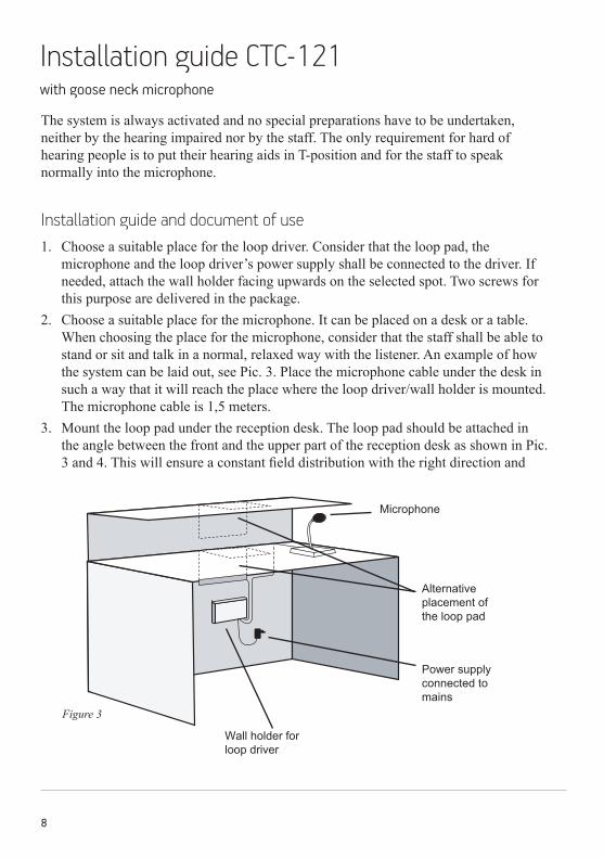
Installation guide CTC-121 with goose neck microphone
Figure 3
The system is always activated and no special preparations have to be undertaken, neither by the hearing impaired nor by the staff. The only requirement for hard of hearing people is to put their hearing aids in T-position and for the staff to speak normally into the microphone.
Installation guide and document of use1. Choose a suitable place for the loop driver. Consider that the loop pad, the
microphone and the loop driver’s power supply shall be connected to the driver. If needed, attach the wall holder facing upwards on the selected spot. Two screws for this purpose are delivered in the package.
2. Choose a suitable place for the microphone. It can be placed on a desk or a table. When choosing the place for the microphone, consider that the staff shall be able to stand or sit and talk in a normal, relaxed way with the listener. An example of how the system can be laid out, see Pic. 3. Place the microphone cable under the desk in such a way that it will reach the place where the loop driver/wall holder is mounted. The microphone cable is 1,5 meters.
3. Mount the loop pad under the reception desk. The loop pad should be attached in the angle between the front and the upper part of the reception desk as shown in Pic. 3 and 4. This will ensure a constant field distribution with the right direction and
Microphone
Alternative placement of the loop pad
Power supply connected to mains
Wall holder for loop driver

9
also allow hearing aid users to tilt their head forwards, for example when writing. When mounting the pad (be careful not to damage the loop cables inside the pad), place the loop pad cable in such a way that it will reach the loop driver/wall holder. The loop pad cable is 10 meters.
4. Connect the cables power supply, loop pad and microphone, see page 1, and connect the power supply to mains. If the wall holder is being used, put the cables from the loop driver’s transformer, loop pad and microphone through the wall holder from underneath. Turn the driver in such a way that the connector side is facing down and you can read the text on the front of the driver in the right direction. Connect all three cables, see page 1. Finally, lower the driver into the wall holder and connect the transformer to mains.
5. When all connections are completed correctly the LED-indicator for mains power on the right hand side of the front of the driver shall light up. The system is now ready to be used.
6. The loop current is adjusted by turning the volume control at the front of the driver. Verify the loop level/volume with a Univox Listener. Bass and treble controls shall only be adjusted in exceptional cases to reach an adjusted frequency rendering.
Figure 4
Microphone
The loop pad can be placed either under the top of the desk or under the top of the reception table.
To place the loop pad in the higher position will enable a stronger magnetic field and thus a better speech perception for hearing aid users.
10
TroubleshootingVerify the control LEDs following the instructions in this installation guide. Use Univox Listener to check the sound quality and basic level of the loop. If the loop driver does not perform satisfactory, check the following:
• Does the mains power indicator light? If not, maek sure that the transformer is correctly connected to the power outlet and to the driver.
• Is the loop current indicator lit? This is a guarantee that the system works. If not, check that the loop pad is not broken and correctly connected, and make sure to check all other connections.
• Attention! If headphones are connected the loop current indicator is disabled.• The loop current indicator lights but there is no sound in the hearing aid/
headphones: check that the M-T-O switch of the hearing aid is in T or MT mode. Also check the status of your hearing aid batteries.
• Bad sound quality? Adjust the loop current, bass and treble controls. Bass and treble adjustment should normally not be needed.
Make sure that Listener is turned on (red LED flashes). If not, change the batteries. Please make sure that the batteries are inserted correctly. If the loop receiver sound is weak, make sure that Listener is hanging/hold in vertical position. Adjust volume if necessary. Weak signal might indicate that the loop system doesn’t comply with the international standard IEC 60118-4.
Should the system not work after having made the product test as described above, please contact your local distributor for further instructions.
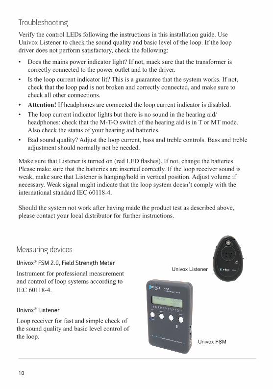
Univox Listener
Univox FSM
Measuring devices
Univox® FSM 2.0, Field Strength Meter
Instrument for professional measurement and control of loop systems according to IEC 60118-4.
Univox® Listener
Loop receiver for fast and simple check of the sound quality and basic level control of the loop.

11
Safety and warrantyBasic knowledge in audio and video installation techniques is required to achieve existing regulations. The installer is responsible for the installation hereby avoiding any risk or cause of fire. Please note that the warranty is not valid for any damage or defects on the product due to incorrect or incautious installation, usage or maintenance.
Bo Edin AB shall not be held responsible or liable for interference to radio or TV equipment, and/or to any direct, incidental or consequential damages or losses to any person or entity, if the equipment has been installed by unqualified personnel and/or if installation instructions stated in the product Installation Guide have not been strictly followed.
Maintenance and careUnder normal circumstances Univox® loop drivers do not need any special maintenance. Should the unit become dirty, wipe it with a clean damp cloth. Do not use solvent or strong detergents.
ServiceShould the product/system not work after having made the product test as described above, please contact the local distributor for further instructions. If the product should be sent to Bo Edin AB, please enclose a filled Service Form, www.univox.eu/Support.
Technical dataFor additional information, please refer to product data sheet/brochure and CE certificate which can be downloaded at www.univox.eu/Downloads. If required other technical documents can be ordered from your local distributor or from [email protected].
EnvironmentWhen this system is finished with, please follow existing disposal regulations. Thus if you respect these instructions you ensure human health and environmental protection.

12
ctc-
ig-g
b-18
0313
Cop
yrig
ht ©
Bo
Edin
AB
Bo Edin AB Stockby Hantverksby 3, 181 75 Lidingö Tel: 08 7671818 Email: [email protected]öksadress Förrådsvägen 2B, 181 41 Lidingö Fax: 08 7671820 Webb: www.edin.se
Hearing excellence since 1965
Univox by edin, the world’s leading expert and producer of high quality hearing loop systems, created the very first true loop amplifier 1969. Ever since our mission is to serve the hearing community with the highest degree of service and performance with strong focus on Research and Development for new technical solutions.