cth-180 (v), cth-180 (i) - chainsaws, lawn mowers ... · fill in and mail the registration card...
TRANSCRIPT

101 90 15-26
CTH-180 (V), CTH-180 (I)
Please read these instructions carefully andmake sure you understand them before usingthe machine.
Operator´s manual

Svenska – 31
Sve-5 225/232/235 Bruk 97-11-25, 08.4631

English – 1
INTERNATIONAL SYMBOLS ....................................................................................... 1SAFETY RULES ........................................................................................................... 2ASSEMBLY ................................................................................................................... 3OPERATION ................................................................................................................. 7
MAINTENANCE ............................................................................................................ 12ADJUSTMENTS ............................................................................................................ 17
WIRING DIAGRAM ....................................................................................................... 21TROUBLESHOOTING GUIDE ...................................................................................... 22
STORAGE ..................................................................................................................... 24TECHNICAL SPECIFICATIONS ................................................................................... 25
Read this manual carefully so that you will know how to assemble, use and maintain this unit.Fill in and mail the registration card provided with the unit. For service other than described in this manual, contact anauthorized service dealer. He will provide you with parts and service.
Note: This lawn tractor is equipped with a combustion engine, which should not be used near any land covered withgrass or brush, unless the engine's exhaust system is equipped with a spark arrester meeting local laws. The operatorshould maintain the spark arrester in effective working order.
INTERNATIONAL SYMBOLS
These symbols appear on your unit and in the supplied documentation.You should learn and understand their meaning.
Read operator s manual.
TABLE OF CONTENTS
R N
!!!!!
Reverse Neutral Fast Slow EngineOff
Choke
Engine start Mower Height Reverse Forward
Engine run ClutchDisengage
Parkingbrake
Brake Warning
RotatingBlades
Europeanmachinery
directive forsafety
Never driveacross a slope
Never use the cutter ifthere are people,
especially children, orpets, in the vicinity.
Transportposition
Forward Do notsmoke
Brake toSTOP
Brakerelease
Checkengine
Keep hands out Never leavetractor whenrunning
Noiselevel
Nevercamypassengers
Do notraise up

2 – English
1. GENERAL OPERATION:• Know controls and how to stop quickly.• Read, understand, and follow all instructions in the manual and on
the machine before starting.• Only allow responsible adults, who are familiar with instructions, to
operate the machine.• Wear safety glasses or eye shields when assembling or operating
the machine.• Do not operate machine when barefoot. Always wear substantial
footwear, preferably steel-toed shoes.• Do not wear loose fitting clothing that could get caught in moving
parts.• Clear the area of objects such as rocks, toys, wires, etc., which
could be picked up and thrown by the blades.• Be sure the area is clear of other people before mowing.• Stop machine if anyone enters the area.• Never carry passengers.• Do not mow in reverse unless absolutely necessary.• Always look down and behind before and while backing.• Be aware of the mower discharge and do not point it at anyone.• Do not operate the mower without the entire grass collector.• Slow down before turning.• Never leave a running machine unattended. Always turn off
blades, set parking, stop engine, and remove keys beforedismounting.
• Turn off blades when not mowing.• Stop engine before removing grass collector.• Mow only in day light or good artificial light.• Do not operate the machine while under the influence of alcohol or
drugs.• Watch for traffic when operating near or crossing roadways.• Use care when mowing around a fixed object to prevent the
blades from striking it. Never deliberately run over any foreignobject.
• Use extra care when loading or unloading the machine into atrailer or truck.
• Use care when pulling loads or using heavy equipment.a. Use only approved drawbar hitch points.b. Limit loads to those that you can safely control.c. Do not run sharply. Use care when backing.d. Use counterweights, wheel weight when suggested inattachments instructions.
2. SLOPE OPERATIONSlopes are a major factor related to loss-control and tip-over accidents,which can result in severe injury or death. All slopes require extra caution.If you cannot back up the slope or if you feel uneasy on it, do not mow it.DO• Mow up and down, not across.• Remove obstacles such as rocks, tree limbs, etc.• Watch for holes, ruts, or bumps. Uneven terrain could overturn the
machine. Tall grass can hide obstacles.• Use slow speed. Choose a low gear so that you will not have to
stop or shift while on slope.• Follow the manufacturer's recommendations for wheel weights or
counterweights to improve stability.• Use extra care with grass collector or other attachment.
This can change the stability of the machine.• Keep all movements on the slope slow and gradual.
Do not make sudden changes in speed or direction.• Avoid starting or stopping on a slope. If tires lose traction, turn off
the blades and proceed slowly down the slope.DO NOT
• Do not turn on slopes unless necessary, and then slowly andgradually downhill, if possible.
• Do not mow near drop-off, ditches or embankments.The mower could suddenly turn over if a wheel is over the edge ofa cliff or ditch, or if an edge caves in.
• Do not mow on wet grass. Reduced traction could cause sliding.• Do not try to stabilize the machine by putting your foot on the
ground.
3. CHILDRENTragic accidents can occur if the operator is not alert to the presence ofchildren. Children are often attracted to the machine and the mowingactivity. Never assume that children will remain where you last saw them.• Keep children out of the mowing area and under the watchful care
of another responsible adult.• Be alert and turn machine off if children enter the area.• Before and when backing, look behind and down for small
children.• Never carry children. They may fall off and be seriously injured or
interfere with safe machine operation.• Never allow children to operate the machine.• Use extra care when approaching blind corners, shrubs, trees, or
other objects that may obscure vision.
4. SERVICE• Use extra care in handling gasoline and other fuels.
a. Use only an approved containerb. Never remove gas cap or add fuel with the engine running.Allow engine to cool before refuelling. Do not smoke.c. Never refuel the machine indoors.d. Never store the machine or fuel container inside wherethere is an open flame, such as in water heater.
• Check fuel supply before each use allowing space for expansionas the heat of the engine and sun can cause gasoline to expandand overflow the tank.
• Use extra care when handling battery acid. Acid contact with skinmay cause severe burns. Eye contact may cause blindness.
• Use extra care when servicing the battery. Explosive gas isproduced in the battery. Do not service the battery while smokingor near open spark or flame. This may cause the battery toexplode causing serious injury.
• Never run a machine inside a closed area. Exhaust fumes containcarbon monoxide, an odourless and deadly gas.
• Keep nuts and bolts, especially blade attachments bolts, tight andkeep equipment in good condition.
• Never tamper with safety devices. Check their operation regularly.• Do not change the engine governor settings or overspread engine.• Reduce fire hazards. Keep machine free of grass, leaves, or other
debris build-up. Clean up oil or fuel spillage. Allow machine tocool before storing.
• Stop and inspect the equipment if you strike an object. Repair, ifnecessary, before restarting.
• Never make adjustments or repairs with the engine running.• Grass collector components are subjects to wear, damage, and
deterioration, which could expose moving parts or allow objects tobe thrown. Frequently check components, and replace withmanufacturer's recommended spare parts, when necessary.
• Mower blades are sharp and can cut. Wrap the blades or weargloves, and use extra caution when servicing them.
• Check brake operating frequently. Adjust and service as required.
SAFETY RULES
THIS SYMBOL MEANS THAT IMPORTANT SAFETY PRECAUTIONS HAVE TO BEPOINTED OUT. YOUR SAFETY IS INVOLVED.!
These instructions are for your protection. You should read them carefully.
WARNING: This lawn tractor is able to cut hands, feet, and throwing objects. If you do notfollow the safety instructions, you could experience serious injuries.! !

English – 3
UNPACKINGThe tractor is not completely assembled at the factory,for transportation reasons.
After removing the packaging, check the machine forany damage during the shipment, locate the hardwarebag and loose parts. Take care while removing themachine from the pallet, to avoid any damage to themower deck.
STANDARD PACKING• tractor• steering wheel• seat with holder• battery• grass collector• trailer hitch• bag with operator's manual, parts manual,
2 keys for ignition, 1 decal with an arrow.• hardware bag for grass collector
IDENTIFICATIONThe tractor identification plate is located under thedriver´s seat and behind the battery. Make a note of theserial number on this page. This serial number will haveto be guoted when contacting your distributor for serviceand ordering spare parts for the tractor. See fig. 1.
Serial No.: ................................................................
STEERING WHEEL (FIG. 2)
Proceed to the following steps:1. Discard the plastic protection from the seat.2. Loosen both nuts from the seat hinges on the
tractor.3. Place the seat and tighten securely with two
bolts, flat and spring washers.4. Connect the safety switch.
SEAT (FIG.3)
Fig. 3
Fig. 2
Proceed to the following steps:1. Straighten the front wheels.2. Align the holes of the steering wheel with the
hole in the steering shaft.MAKE SURE THE STEERING WHEEL ISCENTERED AND THE HOLES LINED UP.
3. Insert the lock pin through the holes, and driveit through the holes with a hammer.
ASSEMBLY
Fig. 1: Identification plate
4 – English
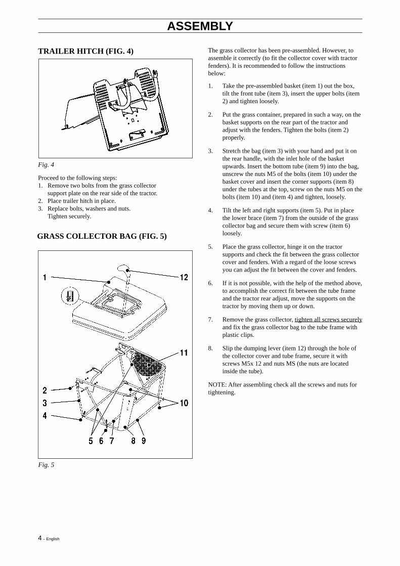
TRAILER HITCH (FIG. 4)
ASSEMBLY
The grass collector has been pre-assembled. However, toassemble it correctly (to fit the collector cover with tractorfenders). It is recommended to follow the instructionsbelow:
1. Take the pre-assembled basket (item 1) out the box,tilt the front tube (item 3), insert the upper bolts (item2) and tighten loosely.
2. Put the grass container, prepared in such a way, on thebasket supports on the rear part of the tractor andadjust with the fenders. Tighten the bolts (item 2)properly.
3. Stretch the bag (item 3) with your hand and put it onthe rear handle, with the inlet hole of the basketupwards. Insert the bottom tube (item 9) into the bag,unscrew the nuts M5 of the bolts (item 10) under thebasket cover and insert the corner supports (item 8)under the tubes at the top, screw on the nuts M5 on thebolts (item 10) and (item 4) and tighten, loosely.
4. Tilt the left and right supports (item 5). Put in placethe lower brace (item 7) from the outside of the grasscollector bag and secure them with screw (item 6)loosely.
5. Place the grass collector, hinge it on the tractorsupports and check the fit between the grass collectorcover and fenders. With a regard of the loose screwsyou can adjust the fit between the cover and fenders.
6. If it is not possible, with the help of the method above,to accomplish the correct fit between the tube frameand the tractor rear adjust, move the supports on thetractor by moving them up or down.
7. Remove the grass collector, tighten all screws securelyand fix the grass collector bag to the tube frame withplastic clips.
8. Slip the dumping lever (item 12) through the hole ofthe collector cover and tube frame, secure it withscrews M5x 12 and nuts MS (the nuts are locatedinside the tube).
NOTE: After assembling check all the screws and nuts fortightening.
Fig. 5
GRASS COLLECTOR BAG (FIG. 5)
Fig. 4
Proceed to the following steps:1. Remove two bolts from the grass collector
support plate on the rear side of the tractor.2. Place trailer hitch in place.3. Replace bolts, washers and nuts.
Tighten securely.
English – 5
ASSEMBLY
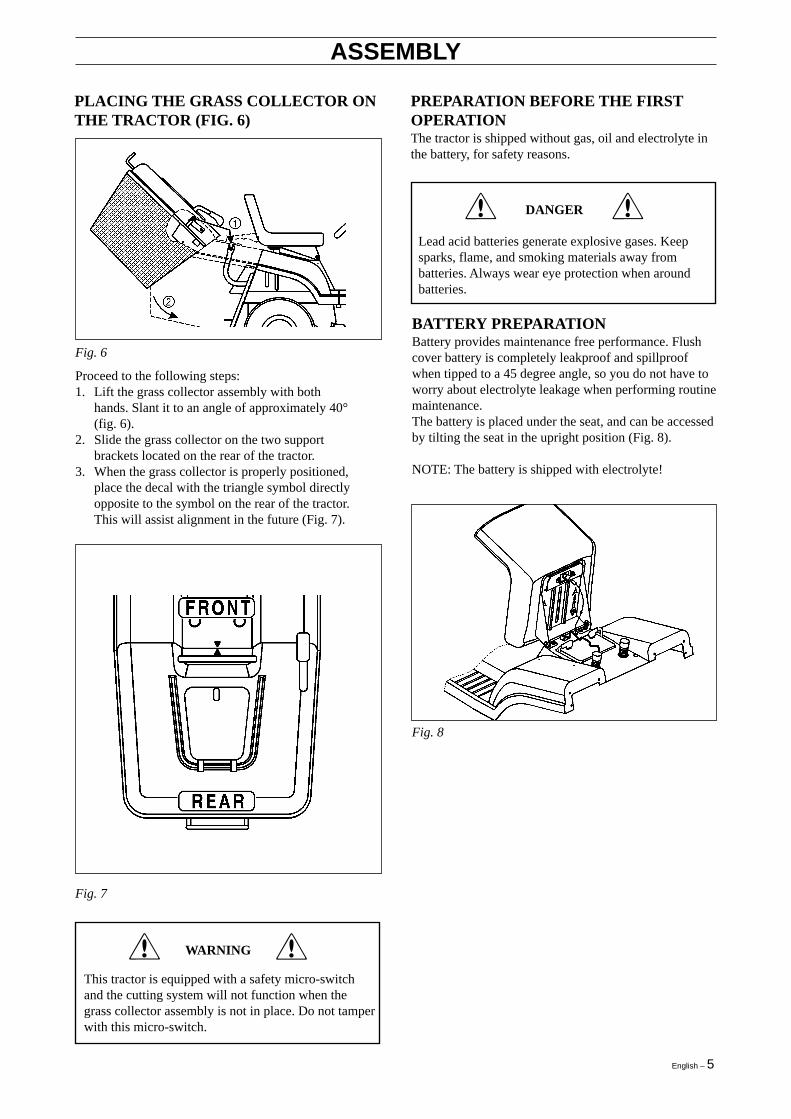
PLACING THE GRASS COLLECTOR ONTHE TRACTOR (FIG. 6)
Fig. 6
Proceed to the following steps:1. Lift the grass collector assembly with both
hands. Slant it to an angle of approximately 40°(fig. 6).
2. Slide the grass collector on the two supportbrackets located on the rear of the tractor.
3. When the grass collector is properly positioned,place the decal with the triangle symbol directlyopposite to the symbol on the rear of the tractor.This will assist alignment in the future (Fig. 7).
PREPARATION BEFORE THE FIRSTOPERATIONThe tractor is shipped without gas, oil and electrolyte inthe battery, for safety reasons.
!! DANGER
Lead acid batteries generate explosive gases. Keepsparks, flame, and smoking materials away frombatteries. Always wear eye protection when aroundbatteries.
BATTERY PREPARATIONBattery provides maintenance free performance. Flushcover battery is completely leakproof and spillproofwhen tipped to a 45 degree angle, so you do not have toworry about electrolyte leakage when performing routinemaintenance.The battery is placed under the seat, and can be accessedby tilting the seat in the upright position (Fig. 8).
NOTE: The battery is shipped with electrolyte!
Fig. 8
!! WARNING
This tractor is equipped with a safety micro-switchand the cutting system will not function when thegrass collector assembly is not in place. Do not tamperwith this micro-switch.
Fig. 7

6 – English
ASSEMBLY
CHECK THE BATTERY
If it is necessary proceed to the following steps:
1. Remove the battery from the tractor.
2. Charge the battery at a rate of 6 amps for 1 hour. Usea 12-volt battery charger. Observe all precautionsrequired for battery charging. Complete the assemblyof your unit while waiting for battery to charge.
3. Check battery case for leakage to make sure that nodamage has occurred while handling.
4. Reinstall the battery and secure it with the springlever (see fig. 8).
Fig. 9
Use only regular unleaded gasoline.The recommended lowest octane level is 95.If the engine runs on petrol with a lower octane levelthan 95, an effect known as knocking can arise. Thisleads to arise in the level of the engine temperature andcan cause engine failure.
REFUELLING
1. Stop the engine and let it cool down.2. Open the petrol cap slowly in order to release any
possible high pressure.3. Tighten the petrol cap carefully after refuelling.4. Dry around the area of the petrol cap. Clean the fuel
tank regularly. Impuritier in the tank can causerunning problems.
For refuelling, use approved container with funnel. Donot overfill the tank, which contains approx. 8 litre.
!! WARNING
Make sure there is good air ventilation when refuel-ling.
!! DANGER
Use extra care in handling fuels. They are flammable,vapours are explosive. Allow the engine to cool downbefore refuelling. Do not smoke. Use safety approvedcontainer only to store your gasoline.
In the operator´s manual for the engine, you will findfuel and oil recommendations.
TYRESProceed to the following steps:
1. Check the tyres pressure: 120 kPa (1,2 BAR) for thefront wheels; 100 kPa (1,0 BAR) for the rear wheels.
2. Adjust pressure up or down if necessary.
NOTE: The tyre pressure is important for an even cut.
TO SERVICE THE ENGINENOTE: The engine is shipped with oil.Fill crankcase with only 15W30 Oil. Do not overfill or itcauses serious damage to the engine.
Before starting the engine, read carefully the enginemanual.
Fig. 10
!! DANGER
Electrolyte is a dangerous acid and poisonous. Alwayswear eye protection. Protect your skin when handlingacid or battery.
POISON/DANGER-CAUSES SEVERE BURNSContains sulfuric acid. Avoid contact with skin, eyesor clothing. To prevent accidents, neutralize excessacid with baking soda and rinse empty container withwater.
ANTIDOTEExternal: Flush with water.Internal: Drink large quantities of water or milk.Follow wiyh milk of magnesia, beaten eggs orvegetable oil. Call a physician immediately.Eyes: Flush with water for 15 minutes and get promptmedical attention.
KEPP OUT OF YHE REACH OF CHILDREN
GAS FILLING

English – 7
CONTROLS1. Dash panel (fig. 11)
a. throttle control leverb. ignition switchc. headlight switchd. switch MAN-AUTO, collector fill gaugee. re-engage switchf. ON/OFF switch, cutting system.
2. Steering wheel3. Choke control4. Cutting height adjustment lever5a. Forward speed pedal5b. Reverse speed pedal6. Parking brake lever7. Brake pedal8. Transmission disengagement lever
OPERATION
Fig. 11
OPERATION AND DESCRIPTION(FIG. 11)
TOGGLE SWITCH CUTTING SYSTEM (f)The mower clutch switch is secured in the off position,in order to avoid accidental engagement. To engage, pullup the switch lever, and place it in the ON position; thisactuates the cutting system clutch, which drives theblades (fig.16).
Fig. 16
MAN/AUTO SWITCH (d)When in AUTO position, the automatic control of thegrass collector filling is set. When the collector is fullwith grass clippings, the overload protection switchlocated inside the grass collector will be mechanicallyactivated and the audible warning buzzer signal cycleshould start after the 1 st second. After a 3 secondsperiod both the buzzer the cuting system will stopoperation.
If it is the MAN position, then the overfill switch isdisabled and the collector tunnel could severely clog.
RE-ENGAGE SWITCH (e)This switch should be pressed to re-activate the MAN/AUTO switch, after the grass collector is emptied.
SEAT ADJUSTMENT (FIG. 12)
In order to adjust the seat, proceed to the followingsteps:1. loosen the thumb screw.2. move the seat forward or backward to the
desired position.3. tighten thumb screw securely.
Fig. 12

8 – English
OPERATION
!! DANGER
Never run the engine indoors, or in enclosed orpoorly ventilated areas. Engine exhaust containscarbon monoxide.
TO START THE ENGINE
To start the engine, proceed as follows:
1. Open the fuel valve. The handle should point downas shown in the fig.13.
Fig. 13
2. Take a comfortable riding position on the seat.The safety switch is connected.
Fig. 14
Fig. 15
3. Depress fully, and hold the brake pedal (fig. 14, pos1).
4. Place the throttle lever at the ”turtle” symbol. Pull thechoke control out.
5. Place the toggle switch ”cutting system” to OFFposition. Fig. 16, pos. OFF
6. Turn the ignition key to START position (Fig. 18)release it immediately when the engine has started(Fig. 18). Continuous cranking of more than 15seconds per minute can cause the starter to overheat.Allow the starter to cool down two minutes aftercranking of more than 15 seconds.
7. After starting the engine slide the choke control toslow position and set the engine speed by the throttlelever (Fig. 17).
Fig. 17
Never run the engine indoors, or in enclosed orpoorly ventilated areas. Engine exhaust containscarbon monoxide.Keep feet, hands and clothes away from the engine.The temperature of the muffler may exceed 80°C.
DANGER !!
Fig. 18
When you want to start the engine, be sure that:
• the brake pedal is depressed
• the mower clutch lever is in disengagedposition
• the grass collector is properly in place
!! DANGER

English – 9
OPERATION
Move the throttle to slow position before turningignition off, in order to reduce muffler pop. Failureto do so will result in engine and exhaust damages.
!! WARNING
The mower deck must be in the highest position, whenyou drive the tractor in transport mode off the lawn. Ifnot, damages will be caused to the blades.
IMPORTANT
! !WARNING
RIDING THE TRACTOR
The tractor is equipped with a hydrostatic transmission.It means that the forward and reverse speed can beachieved with the use of the pedals (Fig. 15).The more depressed the pedals are, the faster the tractormoves. The tractor moves forward and reverse at thesame speed.
BRAKE (FIG. 14)When the pedal is fully depressed, the brake is applied.Then, place the throttle lever at the "turtle" idle position(fig. 17).
The parking brake lever is used to lock the brake pedalin brake position (fig. 14; pos. 2).
REVERSE GEAR (FIG. 15)
!! CAUTION
Come to a full stop before changing direction ofmotion.
Depress slowly the reverse movement pedal(Fig. 15, pos. 2).
!! WARNING
While riding backwards, watch out behind.Do not have your mower engaged!
LAWN CUTTING
• Clear the area of any objects, such as toys,wires, branches, etc.
• Do not wear loose clothes, which could becaught in moving parts.
• Always wear substantial footwear.• Keep out children and animals, while riding.• Keep hands and feet away from the mower
deck.• Never carry passengers.
IMPORTANT
Be sure the cutting system clutch is disengaged and is inthe OFF position before starting engine (fig. 16).
Fig. 16
BLADES CHECKCheck the cutting blades periodically.If dull, you will not get a nice event cut.You must replace or sharpen the blades.After sharpening, you must balance the blades before re-installation.
CUTTING HEIGHT ADJUSTMENT(FIG.19)The cutting height lever is located on the right side offender.The bottom position of the lever is the lowest cuttingheight, and vice versa.
In case the tractor must be pushed, the transmissiondisengagement bypass lever must be put in theforward position.

10 – English
OPERATION
Fig. 19
MOWER DECK GAUGE WHEELS(FIG. 20)
The mower deck gauge wheels must always be in thelower position. Refer to fig. 20.
Fig. 20
IMPORTANT
Before starting cutting grass, take care of the properpositioning of the grass collector.
RIDING AND MOWINGProceed with the following steps:1. Start engine and drive tractor to the lawn.2. When on the lawn, engage mower clutch with
toggle switch (fig. 16).3. Switch the MAN/AUTO button to the lower
AUTO position (fig. 11, d).4. Depress slowly the forward movement pedal to reach
the desired speed.
IMPORTANT
While starting the blades, keep the throttle in themiddle position, to save the belt and clutch frompremature wear and possible damage.
SPEED RANGESThe slowest speed is used for mowing on slopes ormowing high wet grass.The lower the grass is, the higher the speed should be.When tractor is used for transport (not cutting). Depressthe forward movement pedal for maximum speed.
As soon as the blades strike any solid object the shearbolts will break. Immediately stop the engine! Checkthe blades! Replace the broken shear bolts only withfactory originals. Check to make sure that all blademounting bolts are tightened.
IMPORTANT
MOWING HINTS1. We advise mowing the lawn in a longitudinal
and cross direction, overlapping previous cut,which allows the lifting action of the blades intothe cutting path.
2. Forward speed of the lawn tractor must becontrolled in accordance with the type andquantity of grass being mowed.
IMPORTANT
The more grass that must be cut, the slower theforward speed should be.
ALWAYS: In case of any obstacles, immediatelydisengage the blades and lift the mower deck to thehighest level.
English – 11
OPERATION
SLOPE OPERATION• All slopes need extra caution.• Do not cut grass, when slope is more than 10°
(17%).• Mow slopes, riding up and down, never across.• Avoid sudden changes in direction.• Remove obstacles such as rocks, tree limbs,
ruts, etc.
!! WARNING
While travelling downhill, never coast! Whenparking, depress the brake pedal, and lock it (fig. 14,pos. 1 and 2).
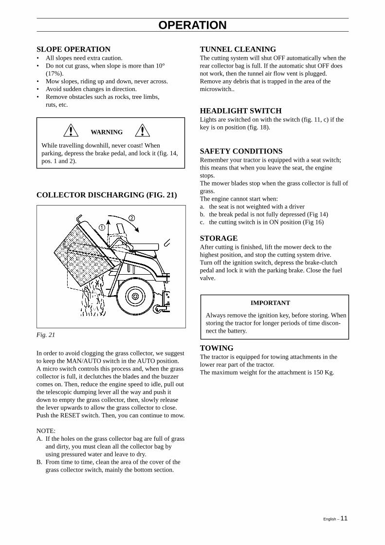
COLLECTOR DISCHARGING (FIG. 21)
In order to avoid clogging the grass collector, we suggestto keep the MAN/AUTO switch in the AUTO position.A micro switch controls this process and, when the grasscollector is full, it declutches the blades and the buzzercomes on. Then, reduce the engine speed to idle, pull outthe telescopic dumping lever all the way and push itdown to empty the grass collector, then, slowly releasethe lever upwards to allow the grass collector to close.Push the RESET switch. Then, you can continue to mow.
NOTE:A. If the holes on the grass collector bag are full of grass
and dirty, you must clean all the collector bag byusing pressured water and leave to dry.
B. From time to time, clean the area of the cover of thegrass collector switch, mainly the bottom section.
Fig. 21
TUNNEL CLEANINGThe cutting system will shut OFF automatically when therear collector bag is full. If the automatic shut OFF doesnot work, then the tunnel air flow vent is plugged.Remove any debris that is trapped in the area of themicroswitch..
HEADLIGHT SWITCHLights are switched on with the switch (fig. 11, c) if thekey is on position (fig. 18).
SAFETY CONDITIONSRemember your tractor is equipped with a seat switch;this means that when you leave the seat, the enginestops.The mower blades stop when the grass collector is full ofgrass.The engine cannot start when:a. the seat is not weighted with a driverb. the break pedal is not fully depressed (Fig 14)c. the cutting switch is in ON position (Fig 16)
STORAGEAfter cutting is finished, lift the mower deck to thehighest position, and stop the cutting system drive.Turn off the ignition switch, depress the brake-clutchpedal and lock it with the parking brake. Close the fuelvalve.
TOWINGThe tractor is equipped for towing attachments in thelower rear part of the tractor.The maximum weight for the attachment is 150 Kg.
IMPORTANT
Always remove the ignition key, before storing. Whenstoring the tractor for longer periods of time discon-nect the battery.

12 – English
After each cut, remove dirt and debris from the machinesurface, the discharge tunnel and the grass collector.
WASHING (FIG. 22)
MAINTENANCE
CLEANING
Before cleaning, washing, servicing or repairing,remove the ignition key!Always wear substantial steel toe foot wear, glovesand work clothes.Be aware of any spilled fuel, oil or other contaminat-ing substances.
!! WARNING
Fig. 22
Proceed with the following:1. Wash the tractor on a levelled surface, with
the grass collector mounted on.2. Wash the inside of the mower deck, and the
discharge tunnel (engine off).3. Dismount the grass collector, wash it, and
leave it off to let it dry.4. Clean the plastic parts of the tractor with a
sponge and soap water.
Avoid water directly near the switches, the dash orany electrical part.
!! BE CAREFUL
To clean the tractor never use high pressure washingmachines, or aggressive detergents.
ENGINE OPERATIONFollow the instruction described in the engine operator'smanual, for operation, service (air filter, fuel filter, oilchange, spark plugs, etc.)
CRANKCASE OIL CHANGECrankcase oil should be changed after the first 5 hours ofoperation.
IMPORTANT
The warranty on this lawn tractor does not cover itemsthat have been subjected to operator abuse or negligence.To receive full value from the warranty, operator mustmaintain lawn tractor as instructed in this manual. Thefollowing maintenance check list is supplied to assistoperator to properly maintain lawn tractor. This is acheck list only. Adjustments referred to will be found inthe Adjustment section of this manual.
Your tractor is equipped with an oil drain plug.
1. Place a flat bottom 2 litres container beneath theoil valve.Note: It may be necessary to raise the left sideof the tractor (with blocks under left wheels) toget proper drainage.
2. Turn the oil valve counterclockwise, and pullto drain oil.Note: The oil fill cap should be loosened toserve as an air vent.
3. To close oil drain valve, push and turnclockwise.
4. Fill with grade SAE 30 or SAE 10W/30W oil.5. Reinstall the oil cap.6. Check that the crankcase oil is at the correct level on
the oil dip stick.
IMPORTANT
See engine operating and maintenance manual forproper procedure.

English – 13
MAINTENANCE
l l
l l
ll
l
l
l l
l
l1,2
l1,2
l 2
SERVICE RECORD
FILL IN DATESAS YOU COMPLETEREGULAR SERVICE
MAINTENANCE CHECKLISTBEFORE STORAGE
BEGINNING EACH SEASON
EVERY 100 HOURS
EVERY 50 HOURS
EVERY 25 HOURS
MONTHLY
FREQUENTLY
AFTER FIRST 20 HOURS
AFTER FIRST 5 HOURS
AFTER FIRST 2 HOURS
BEFORE EACH USE
Check engine oil level
Change engine oil
Change spark plug
Replace air filter paper cartridge
Clean air screen
Inspect muffler/spark arrester
Replace fuel filter
Check battery fluid level/recharge
Clean battery and terminals
Check brake operation
Check transmission cooling
Check tire pressure (Fr: 1,2 bar; Rr: 1,0 bar)
Sharpen or replace mower blades
Check for loose fasteners
Clean lawn tractor
Disconnect battery cables
See lubrication chart
Adjust mower deck drive cog belt
l
l
l
l
l l
l l
l
l
l
l
l
l
l 3
NOTES: 1. Change more often when operating under a heavy load or in high temperatures (35°C and above). 2. Service more oftenwhen operating in dirty or dusty conditions. 3. Replace more often when mowing in sandy soil.
TO BLOCK UP THE TRACTORWhen the tractor is to be blocked up, use a jack lift it onsupport stands. Block up the tractor as follows:
1. Place a jack under the rear axle transmission and liftthe rear end of the tractor.
2. Place two stands under the rear axle, one stand at theinner side of each rear wheel.
3. Lift the front end and place two stands under thefront axle beam, one stand at the inner side of eachwheel spindle.
CAUTIONAt no time during maintenance or adjustment, thetractor can be lifted more than 50 cm from levelposition, without taking the following precautions:1. Remove fuel from the tank and run the
engine until the carburettor is dry.2. Remove battery (See Battery removal
paragraph in the Maintenance section).3. Remove oil from crankcase.
LUBRICATIONFor lubrication frequency see Maintenance check list.For lubrication points and type of lubricant, see Lubrica-tion chart. The transmission has been lubricated for life.
ENGINE MAINTENANCESee Engine operating and maintenance manual formaintenance instructions.
l
l

14 – English
LUBRICATION (FIG 23)
Fig. 23
LUBRICATION LIST
Item Name Number Term-hours Lubricant
1 Front wheel - grease fitting 2 25 Grease2 Steering ball-joints 4 50 Oil3 Steering sector gear 1 50 Grease4 Steering pinion gear 1 25 Grease5 Steering shaft bearing 1 50 Oil6 Steering shaft bearing 1 50 Oil7 Movement lever - grease fitting 1 50 Oil8 Shaft hub for lifting the mower deck 1 50 Oil9 Moving ling ball-joints 4 50 Oil10 Diagonal shaft - grease fitting 2 25 Grease11 Brake pedal hub 2 50 Oil12 Parking brake ring 1 50 Oil13 Steering bearing 1 25 Grease14 Left & Right spindle - grease fitting 2 25 Grease15 Mower deck hinged pin 6 when dismounted Grease16 Front axle pivot pin 2 when dismounted Grease
MAINTENANCE
English – 15
The bearings in idler pulley and retainer pulleys are lifetime lubricated. Gear box is filled with oil.
!! DANGER
Lead acid batteries generate explosive gases. Keepsparks, flame and smoking materials away frombattery. Always wear eye protection when aroundbatteries.
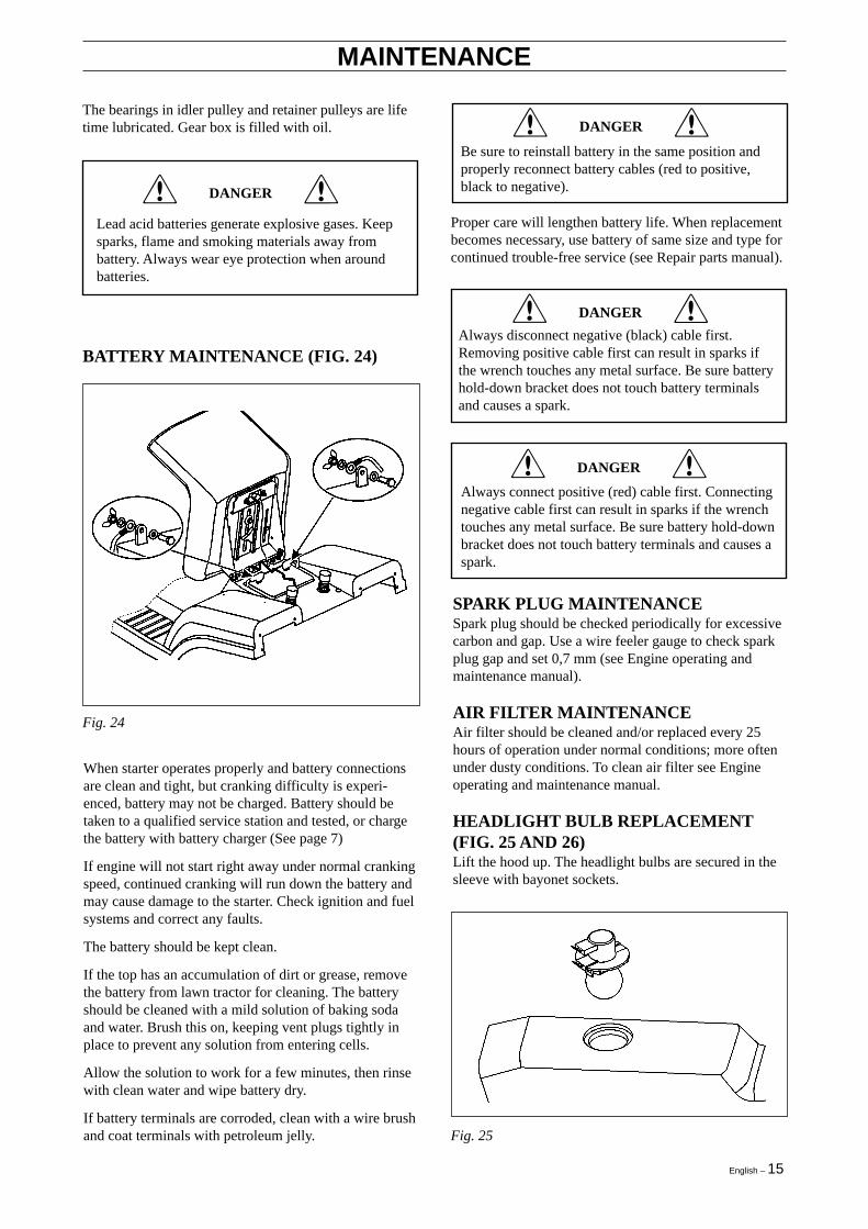
BATTERY MAINTENANCE (FIG. 24)
MAINTENANCE
Fig. 24
When starter operates properly and battery connectionsare clean and tight, but cranking difficulty is experi-enced, battery may not be charged. Battery should betaken to a qualified service station and tested, or chargethe battery with battery charger (See page 7)
If engine will not start right away under normal crankingspeed, continued cranking will run down the battery andmay cause damage to the starter. Check ignition and fuelsystems and correct any faults.
The battery should be kept clean.
If the top has an accumulation of dirt or grease, removethe battery from lawn tractor for cleaning. The batteryshould be cleaned with a mild solution of baking sodaand water. Brush this on, keeping vent plugs tightly inplace to prevent any solution from entering cells.
Allow the solution to work for a few minutes, then rinsewith clean water and wipe battery dry.
If battery terminals are corroded, clean with a wire brushand coat terminals with petroleum jelly.
!! DANGER
Be sure to reinstall battery in the same position andproperly reconnect battery cables (red to positive,black to negative).
Proper care will lengthen battery life. When replacementbecomes necessary, use battery of same size and type forcontinued trouble-free service (see Repair parts manual).
!! DANGER
Always disconnect negative (black) cable first.Removing positive cable first can result in sparks ifthe wrench touches any metal surface. Be sure batteryhold-down bracket does not touch battery terminalsand causes a spark.
!! DANGER
Always connect positive (red) cable first. Connectingnegative cable first can result in sparks if the wrenchtouches any metal surface. Be sure battery hold-downbracket does not touch battery terminals and causes aspark.
SPARK PLUG MAINTENANCESpark plug should be checked periodically for excessivecarbon and gap. Use a wire feeler gauge to check sparkplug gap and set 0,7 mm (see Engine operating andmaintenance manual).
AIR FILTER MAINTENANCEAir filter should be cleaned and/or replaced every 25hours of operation under normal conditions; more oftenunder dusty conditions. To clean air filter see Engineoperating and maintenance manual.
HEADLIGHT BULB REPLACEMENT(FIG. 25 AND 26)Lift the hood up. The headlight bulbs are secured in thesleeve with bayonet sockets.
Fig. 25

16 – English
MAINTENANCE
Fig. 26
FUSE EXCHANGEThe fuse box is placed under the dash.Proceed as follows:1. Lift the hood up.2. Pick out the fuse and replace it by another one
of the same value (15A).If it is still impossible to start the engine, callyour service dealer.
WHEEL EXCHANGE (FIG. 27)
Fig. 27
Proceed as follows:1. Switch off ignition.2. Lift up the tractor and place it on stands.3. Remove plastic cover.4. Dismount the retaining ring, the flat washer, and
remove the wheel. Note: For a rear wheel,watch the key and the key groove.
English – 17
ADJUSTMENTS
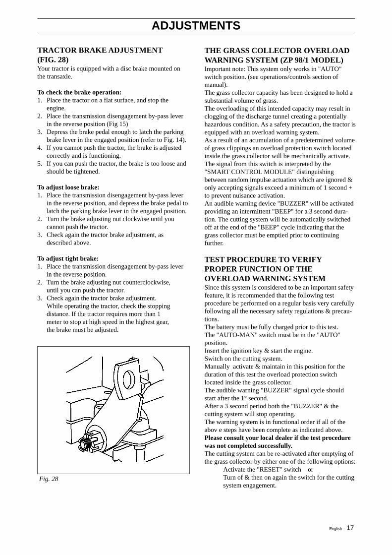
TRACTOR BRAKE ADJUSTMENT(FIG. 28)Your tractor is equipped with a disc brake mounted onthe transaxle.
To check the brake operation:1. Place the tractor on a flat surface, and stop the
engine.2. Place the transmission disengagement by-pass lever
in the reverse position (Fig 15)3. Depress the brake pedal enough to latch the parking
brake lever in the engaged position (refer to Fig. 14).4. If you cannot push the tractor, the brake is adjusted
correctly and is functioning.5. If you can push the tractor, the brake is too loose and
should be tightened.
To adjust loose brake:1. Place the transmission disengagement by-pass lever
in the reverse position, and depress the brake pedal tolatch the parking brake lever in the engaged position.
2. Turn the brake adjusting nut clockwise until youcannot push the tractor.
3. Check again the tractor brake adjustment, asdescribed above.
To adjust tight brake:1. Place the transmission disengagement by-pass lever
in the reverse position.2. Turn the brake adjusting nut counterclockwise,
until you can push the tractor.3. Check again the tractor brake adjustment.
While operating the tractor, check the stoppingdistance. If the tractor requires more than 1meter to stop at high speed in the highest gear,the brake must be adjusted.
Fig. 28
THE GRASS COLLECTOR OVERLOADWARNING SYSTEM (ZP 98/1 MODEL)Important note: This system only works in "AUTO"switch position. (see operations/controls section ofmanual).The grass collector capacity has been designed to hold asubstantial volume of grass.The overloading of this intended capacity may result inclogging of the discharge tunnel creating a potentiallyhazardous condition. As a safety precaution, the tractor isequipped with an overload warning system.As a result of an acumulation of a predetermined volumeof grass clippings an overload protection switch locatedinside the grass collector will be mechanically activate.The signal from this switch is interpreted by the"SMART CONTROL MODULE" distinguishingbetween random impulse actuation which are ignored &only accepting signals exceed a minimum of 1 second +to prevent nuisance activation.An audible warning device "BUZZER" will be activatedproviding an intermittent "BEEP" for a 3 second dura-tion. The cutting system will be automatically switchedoff at the end of the "BEEP" cycle indicating that thegrass collector must be emptied prior to continuingfurther.
TEST PROCEDURE TO VERIFYPROPER FUNCTION OF THEOVERLOAD WARNING SYSTEMSince this system is considered to be an important safetyfeature, it is recommended that the following testprocedure be performed on a regular basis very carefullyfollowing all the necessary safety regulations & precau-tions.The battery must be fully charged prior to this test.The "AUTO-MAN" switch must be in the "AUTO"position.Insert the ignition key & start the engine.Switch on the cutting system.Manually activate & maintain in this position for theduration of this test the overload protection switchlocated inside the grass collector.The audible warning "BUZZER" signal cycle shouldstart after the 1st second.After a 3 second period both the "BUZZER" & thecutting system will stop operating.The warning system is in functional order if all of theabov e steps have been complete as indicated above.Please consult your local dealer if the test procedurewas not completed successfully.The cutting system can be re-activated after emptying ofthe grass collector by either one of the following options:
Activate the "RESET" switch orTurn of & then on again the switch for the cuttingsystem engagement.
18 – English
ADJUSTMENTS
SERVICINGIn the event of system failure, there is a manual position"MAN" switch option which allows for a temporaryover-ride of the overload warning system. It is recom-mended that this be only used as a back-up & only untilnecessary repairs can be arranged. A temporary by-passservice connector has been included in the originaltractor kit & should be installed while the system isbeing serviced. This service connector will provide ashunt path & will shut-off hte cutting system immedi-ately upon receiving a signal from the collector overloadswitch indicating a full grass collector condition.
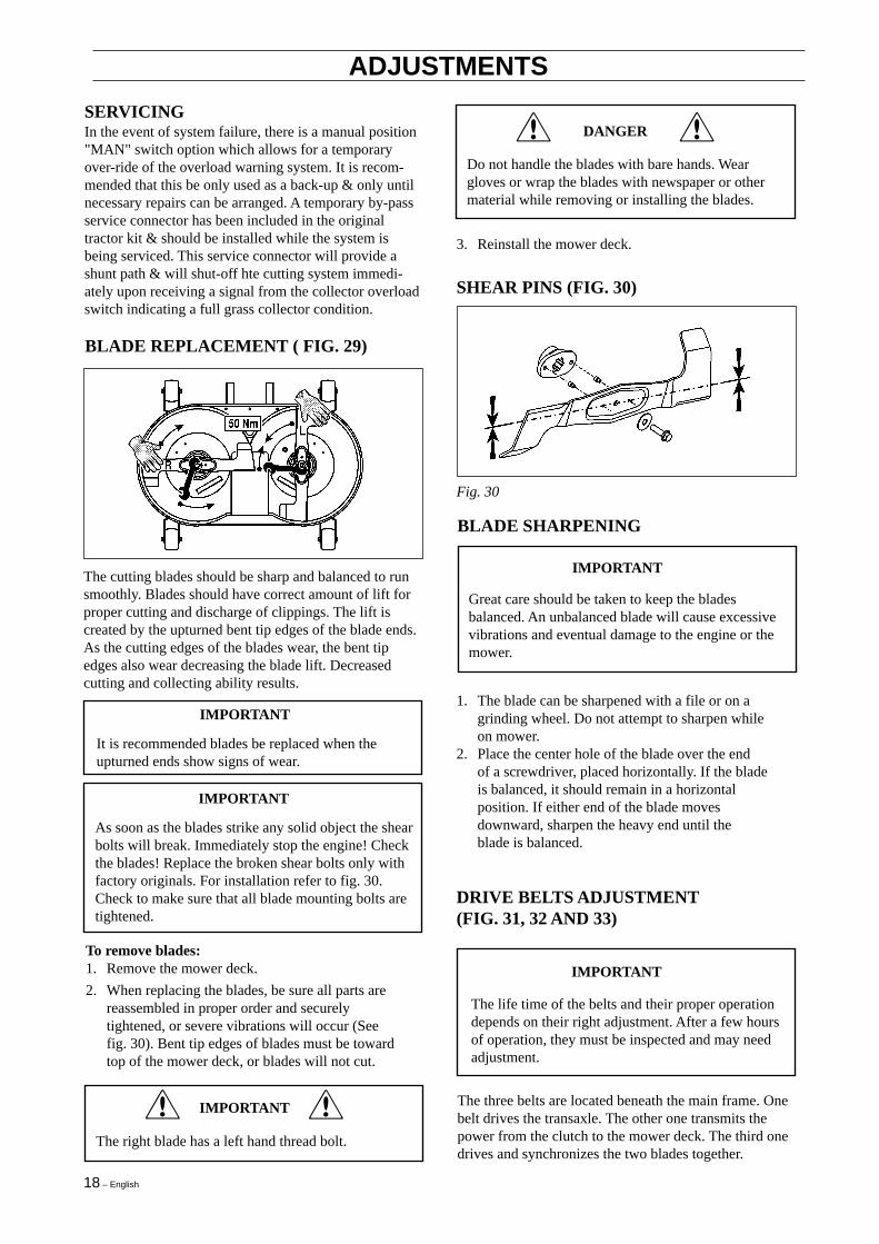
IMPORTANT
As soon as the blades strike any solid object the shearbolts will break. Immediately stop the engine! Checkthe blades! Replace the broken shear bolts only withfactory originals. For installation refer to fig. 30.Check to make sure that all blade mounting bolts aretightened.
To remove blades:1. Remove the mower deck.
2. When replacing the blades, be sure all parts arereassembled in proper order and securelytightened, or severe vibrations will occur (Seefig. 30). Bent tip edges of blades must be towardtop of the mower deck, or blades will not cut.
IMPORTANT
The right blade has a left hand thread bolt.
!! DANGER
Do not handle the blades with bare hands. Weargloves or wrap the blades with newspaper or othermaterial while removing or installing the blades.
3. Reinstall the mower deck.
!!
Fig. 30
SHEAR PINS (FIG. 30)
BLADE SHARPENING
Great care should be taken to keep the bladesbalanced. An unbalanced blade will cause excessivevibrations and eventual damage to the engine or themower.
IMPORTANT
1. The blade can be sharpened with a file or on agrinding wheel. Do not attempt to sharpen whileon mower.
2. Place the center hole of the blade over the endof a screwdriver, placed horizontally. If the bladeis balanced, it should remain in a horizontalposition. If either end of the blade movesdownward, sharpen the heavy end until theblade is balanced.
DRIVE BELTS ADJUSTMENT(FIG. 31, 32 AND 33)
The life time of the belts and their proper operationdepends on their right adjustment. After a few hoursof operation, they must be inspected and may needadjustment.
IMPORTANT
The three belts are located beneath the main frame. Onebelt drives the transaxle. The other one transmits thepower from the clutch to the mower deck. The third onedrives and synchronizes the two blades together.
BLADE REPLACEMENT ( FIG. 29)
The cutting blades should be sharp and balanced to runsmoothly. Blades should have correct amount of lift forproper cutting and discharge of clippings. The lift iscreated by the upturned bent tip edges of the blade ends.As the cutting edges of the blades wear, the bent tipedges also wear decreasing the blade lift. Decreasedcutting and collecting ability results.
IMPORTANT
It is recommended blades be replaced when theupturned ends show signs of wear.

English – 19
ADJUSTMENTS
TRANSMISSION DRIVE BELT (FIG. 31)
Fig. 31
MOWER DECK BELT (FIG. 33)
ADJUST THE MOWER COG BELTNOTE: It is recommended that the mower cog belt beadjusted after 20 hours of operation as the new belts willstretch slightly during the initial break in period.
1. engine pulley2. pulley3. idler pulley
Adjust the tension of the belt with the pulley 3.
MOWER CLUTCH BELT (FIG. 32)
The tension of the belt is automatically adjusted with thespring loaded idler pulley.
NOTE: Longer end of hook-spring must be connected tothe tractor chassis. Short end of hook-spring must beconnected to mower deck.
A. CUTTING OAN REMOVAL (FIG 41)
1. Lower the cutting pan to the lowest position.2. Pull idler arm assembly in and remove V-belt from
pulley.3. Disconnect the spring from the engagement lever.
Fig. 41
4. Remove overload switch plate..5. Lift tunnel to release the lower part from the two
welded pins that connect it to the mower deckassembly.
6. Pull out tunnel rearwards approximately 10 cm(100 mm). Secure the tunnel to prevent it fromfalling back down.
7. Remove the hair pin clips from front pin and fromthe two rear pins.NOTE: It is recommended to loosen the large springfor safety and to facilitate reinstalation of cutting pan.To do so you must remove tunnel.
8. Pull out rear pin from one side and then use a pair ofpliers to pull second rear pin from other side.
CAUTIONIf the large spring has not been loosened, the pivotarm assembly will not spring up with force. Do notplace hands or fingers above the pivot arm assemblyand use pliers when pulling out second rear pin.
9. pull out fron pin10. Remove V-belt from electro magnetic clutch11. Slide cutting pan out from side of tractor
B. ADJUSTMENT PROCEDURES FORCOG BELT TENSION1. Remove cutting pan from tractor, follow procedure
described in A.2. Remove V-belt pulley and idler arm assy.3. Remove plastic belt cover.4. Loosen the two hex nuts on the cog idler pulley on
tension bracket idler.5. Adjust nut M10 until the specified tension at cog belt
is reached. (See Fig 33)
Fig. 32

20 – English
ADJUSTMENTS
6 Re-tighten the two hex nuts on the cog idler pulleyand the belt is now adjusted correctly.
7. To re-install the cutting pan - reverse the procedure.
Note: It is possible but not desirable to adjust the cogbelt tension without removing the cutting pan assemblyform the tractor. In this case follow step 2 through 8from the above procedures.
DANGERThis cog belt must be properly adjusted. If not, theblades can contact and the belt will be destroyed andthe cutting system will be damaged.
Fig. 33
DANGEROn impact with any hard objects, the blade shear boltswill break and the cog belt will be damaged!The cog belt must be inspected.
Be careful!The two blades must be positioned 90 degrees to eachother.
Replacement:Use always genuine parts.
Fig. 34
TORQUE SPECIFICATIONS
Cutting system:Mower cog belt See Fig 33Blade bolt LH 50 NmBlade bolt RH 50 NmHousing bolts M8x30 32 NmSelf locking nut M12(Pulley) 65 NmHexagon socket screwM8x25 (Idler arm) 25 Nm
Steering tooth gear fasteners:Screw M8x20 25 NmLock nut M12 80 Nm
Engine-transmission drive:Exhaust screws 16 NmCrank shaft bolt 108 NmScrew M10x40(Idler pulles) 40 NmSelf-locking nut M8 15-20 Nm(Idler arm)
ADJUSTMENT PROCEDURES FOR THEHEIGHT ADJUSTMENT CABLE ASSY1. Place the tractor on a flat surface, concrete, if
possible.2. Move the lower pin of the front adjustment suspen-
sion into the bottom position of the slotted holes byadjusting the two nuts M12 on the front suspension.
3. Using the height adjustment lever, lift the cutting panto the mid-position.
4. Insert a 6 mm thick board under the rear cutting pangauge wheels.
5. Let the cutting pan down until the rear gauge wheelsrest on the board.
6. Position the height adjustment lever to position 1.7. Keep adjustment self-locking nut 5/16-18 at the end
of the height adjustment cable assyuntil the cable isslightly tight only.
8. Lift the cutting pan and take out the board.
English – 21
WIRING DIAGRAM
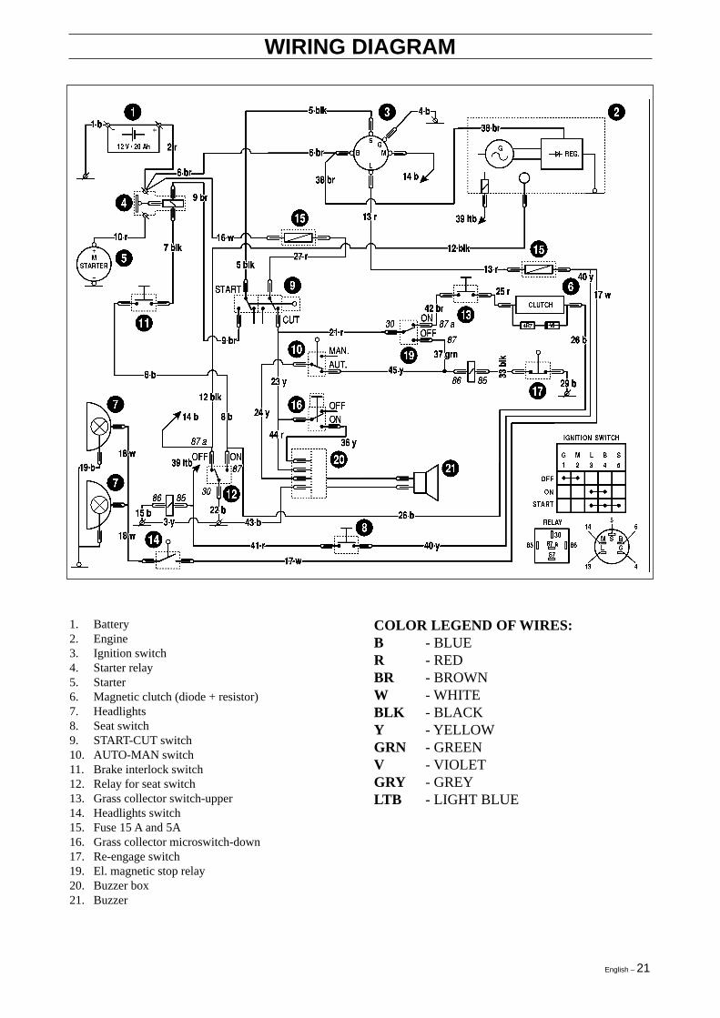
COLOR LEGEND OF WIRES:B - BLUER - REDBR - BROWNW - WHITEBLK - BLACKY - YELLOWGRN - GREENV - VIOLETGRY - GREYLTB - LIGHT BLUE
1. Battery2. Engine3. Ignition switch4. Starter relay5. Starter6. Magnetic clutch (diode + resistor)7. Headlights8. Seat switch9. START-CUT switch10. AUTO-MAN switch11. Brake interlock switch12. Relay for seat switch13. Grass collector switch-upper14. Headlights switch15. Fuse 15 A and 5A16. Grass collector microswitch-down17. Re-engage switch19. El. magnetic stop relay20. Buzzer box21. Buzzer

22 – English
TROUBLESHOOTING GUIDE
PROBLEM CORRECTION
Mower cuts ragged oruneven
Mower leavesunmowed stripbetween blades
Mower scalps lawn
Mower will notdischarge clippings
Blade drive belt comesoff during use
Blade drive belt slips
Blade drive belt wearsexcessively
Blades will not engage
1. Remove any accumulation of grass clippings from underside of mower deck housing.2. Make sure blades are sharp and in good condition (not bent or incorrectly mounted).3. Check blade mounting screws. Blade screws must be tight.4. Check mower deck leveling adjustment per manual. Adjust if necessary.5. Check blade belt tension per manual. Adjust if necessary.6. Check quill assemblies for damage or wear. Replace if necessary.7. Check for possible damage to mower deck housing. Repair or replace if necessary.
1. Mowing a heavy stand of grass or grass with excessive surface moisture could allow mower to leave anunmowed strip.
2. Forward speed should be adjusted to mowing conditions by gear selection. Engine should be run at fullthrottle.
3. Make sure blades are sharp and in good condition. Replace if necessary.4. Check blade belt tension. Adjust if necessary.5. Check quill assemblies for damage or wear. Replace if necessary.6. Check for damage to mower deck housing. Repair if necessary.
1. Check mower height adjustment setting and readjust if neaded. Scalping is more likely on rough or unevenlawns.
2. Check for damage to mower deck housing. repair if necessary.3. Check for bent blades or quills assemblies. Replace if necessary.4. Check mower deck leveling adjustment and adjust if necessary.
1. Remove any accumulation of grass clippings from underside of mower deck housing.2. Wet conditions can cause the discharge funnel and underside of mower deck to become plugged with
clippings. Do not mow wet grass.3. Forward speed should be adjusted to mowing conditions by gear selection. Engine should be run at full
throttle.4. When mowing long grass make first cutting in high position, then recut at normal cutting height.5. Check drive belt tension per manual. Adjust if necessary.6. If blades have been replaced, make sure they have been properly mounted.
1. Blade drive belt may suffer internal damage to cords when it comes off during use. If belt comes off afterchecking all steps below, replace with a new original equipment belt.
2. Check belt tension per manual. Adjust if necessary.3. Check belt guide. Correct clearance is 1,5 mm from belt when blade engage lever is engaged.4. Check mower deck leveling adjustment per manual. Adjust if necessary.5. Check for and remove any foreign objects interfering with belt travel.6. Check all pulleys on mower deck. A bent or split pulley could cause problems. Replace if necessary.7. Check engine drive pulley inner surface. If inner surface is rough or split, pulley should be replaced.8. Check blade engagement idler assembly for wear. Replace necessary parts.
1. If grass is too high or wet, belt slippage may occur.2. Check belt for wear or damage. Replace if necessary.3. Check blade belt tension per manual. Adjust if necessary.4. Check blade drive belt tension spring. If spring is stretched or damaged, replace spring.
1. Check all belt guides. Correct clearance is 1,5 mm from belt when blade engage level is engaged.2. Check for and remove any foreign objects interfering with belt travel.3. Check pulleys for damage. Replace if necessary.4. Make sure blade brake is clearing belt when mower clutch lever is engaged. Adjust or replace if necessary.5. Make sure mower deck leveling adjustment is correct. Adjust when necessary.6. Check blade belt tension per manual. Adjust if necessary.
1. Check belt. If worn or broken, replace. If belt is too loose, make belt adjustment.2. Check engagement spring on deck engagement idler. If broken or damaged, replace.3. Check for and remove any foreign objects interfering with engagement idler travel.

English – 23
TROUBLESHOOTING GUIDE
PROBLEM
1. Check blades and make sure they are not bent, out of balance or loose. Replace if necessary.2. Check belt for burn spots or irregularities that might cause vibrations. Replace if necessary.3. Check quill assemblies for damage or wear. Replace if necessary.4. Check for worn or damaged blade engagement parts. Repair or replace if necessary.5. Check engine drive pulley inner surface. If inner surface is rough or split, pulley should be replaced.6. Check under side of mower deck housing for accumulation of clippings. Remove accumulated clippings.7. Check for loose or damaged engine mounts. Tighten or replace as necessary.8. Check blade belt tension per manual. Adjust if necessary.
1. Check unit drive belt adjustment. Ajust if necessary.2. Check for damaged or broken clutching idler spring. Replace if necessary.3. Check belt for wear or damage. Replace if necessary.4. Check for and remove any foreign objects obstructing clutching idler mechanism.5. Check for split engine or transmission pulley. Replace if necessary.6. On Shift-on-the-Go units, check for proper free play in cable adjustment.
1. Check mower height adjustment setting and readjust if needed. Scalping is more likely on rough or unevenlawns.
2. Check for damage to mower deck housing; repair if necessary.3. Check for bent blades or quill assemblies. Replace if necessary.4. Check mower deck levelling adjustment and adjust it if necessary.
1. Check lawn tractor drive belt adjustment and lawn tractor brake adjustment per manual. Adjust if necessary.2. Check for and remove any foreign objects obstructing clutching idler mechanism.
1. Check belt tension. Adjust if necessary.2. Check belt guides. Adjust if necessary.3. Check for split or damaged pulleys. Replace if necessary.4. Check clutching idler pulley alignment. If out of alignment, idler bracket may be bent. Replace if necessary.
1. See steps 1 through 5 in Unit drive belt slips section of this chart.2. Check engine, transmission or transaxle pulley for sheared or missing key. Replace if necessary.3. Check transaxle to make sure it is operable.
1. Check for split or damaged pulley. Replace if necessary.2. Check belt for irregularities or burned spots. Replace if necessary.3. Make sure belt tension is correct. Adjust if necessary.4. Check clutching idler assembly for wear or damage. Replace parts if necessary.
1. Check shifting procedure.2. Check lawn tractor drive belt adjustment and lawn tractor brake adjustment per manual. Adjust if necessary.3. Have transaxle checked by an authorized service dealer.
1. Check for steering sector gear and pinion looseness. If gears are loose, make sector gear adjustment.2. Check ball joints for wear. Replace if necessary.
1. Check starting procedure. Make sure starting instructions are followed.2. Check fuse.3. Check battery for charge. Make sure battery has been activated and charged.4. On new units, remove spark plug and check cylinder for accumulation of oil due to improper handling.5. Make visual check of electrical system to make sure all connections and lockout switches are secure.6. Check engine according to engine manufacturer’s instructions.7. Have electrical system checked by an authorized service dealer.
1. Check starting procedure. Make sure starting instructions are followed.2. Make sure fuel tank is filled with clean, fresh fuel.3. Make sure fuel shut-off is open.4. Make sure that throttle is in start or fast position.5. Check engine according to engine manufacturer’s instructions.6. Have wiring and lockout switches checked by an authorized service dealer.7. Check fuel filter for obstructions.8. Check for choke usage.
1. Take away the grass collector, and clean the discharge tunnel.
Extreme vibrationoccurs when blade isengaged
Unit drive belt slips
Mower scalps lawn
Unit drive belt squealswhen brake is applied
Unit drive belt comesoff during use
Unit will not propelitself when clutch isengaged
Extreme vibrationoccurs when clutch isengaged
Unit will not shift orshifts hard
Steering slips or isloose
Engine will not turnover
Engine turns over butwill not start
Blocked dischargefunnel
CORRECTION

24 – English
The tractor should be immediately prepared for storageat the end of the season, or if the unit is to be unused for30 days or more. Fuel, if permitted to stand unused forextended periods (30 days or more), may developgummy deposits which can adversely affect the enginecarburettor and can cause engine malfunction.
STORAGE
Chart (page 16).5. Remove the battery (See the Battery removal
paragraph, in Assembly section of this manual).6. Clean the battery as described in the Battery
maintenance paragraph of the Maintenancesection of this manual. Add clean water to raiselevel to indicator ring and fully charge thebattery. A discharged battery will freeze and mayburst. If possible, place the battery in a cool, dryarea. Charge the battery overnight every 30days.
7. Store the tractor in a clean, dry area, and coverit for additional protection.
A yearly check-up or a tune-up by an authorized servicedealer is a good way of insuring that your tractor willprovide maximum performance for the next season.
NOTE: Fuel stabilizer is an acceptable alternative inminimizing the formation of gum deposits duringstorage. Add stabilizer to the fuel in the fuel tank orstorage container. Always follow the mix ratio given bythe stabilizer manufacturer. Run the engine at least 10minutes after adding stabilizer to allow the stabilizer toreach the carburetter. Do not drain the gas tank andcarburetter if using stabilizer.
To prepare the tractor for storage, proceed as follows:1. Clean the tractor thoroughly.2. Inspect the tractor for worn or damaged parts
and tighten all loose screws and nuts.3. Prepare engine for storage (See the engine
operating and maintenance manual).4. Lubricate all points shown in the Lubrication
Never store engine with fuel in tank indoors orpoorly ventilated enclosures, where fuel fumes mayreach an open flame, spark or pilot light as on afurnace, water heater, clothes dryer, etc...Handle fuel carefully. It is highly flammable andcareless use could result in serious fire damage toyour person and property.Drain fuel into an approved container outdoors awayfrom open flame.
DANGER
´*3!T¶6e¨

English – 25
TECHNICAL SPECIFICATIONS
Engine: 18 HP VANGUARD V-TWIN Briggs & Stratton *18 HP INTEK V-TWIN Briggs & Stratton *
Battery: 12 Volts/22 Ah
Front tyres: 16 X 6.50 - 8
Rear tyres: 20 X 10.00 - 8
Front tyres pressure: 100 kPa (1 Bar)
Rear tyres pressure: 70 kPa (0,7 Bar)
Transaxle: HYDRO-GEAR MODEL NO: 310-0650Forward speed 0 - 9 km/hReverse speed 0 - 4 km/h
Turning radius: 74 cm
Cutting heights: 7 heights: from 25 to 100 mm
Mowing size: Twin-blade; 102 cm
Mower deck: Suspended
Blade clutch: Warner Electro-magnetic clutch
Discharge: Rear, with grass collector as standard
Weight (18 HP): Gross: 262 Kg Net: 247 Kg
Tractor dimensions (L x W x H): 240 x 106 x 110 cm
IMPORTANT* Refer to model and type numbers when purchasing replacement parts.
For improvement purposes, specifications and design are subject to change, without notice.Please be advised that no legal claims, of whatsoever they might be, can be used upon the information contained in thismanual.
When performing repairs, make sure that only genuine parts are used. Use of non-original parts will void the warranty.

26 – English
´*3!T¶6e¨ 1998W46