cti magazine
DESCRIPTION
CTI Magazine - December 2013First IssueThe Automotive TM, HEV & EV Drives Magazine by CTIThe Magazine covers topics such as The Opportunity of Advance Automatic Transmission in China The All-Wheel-Drive Powertrain of the New Compact Vehicles of Mercedes-Benz ISO 26262 Process Certificationand many more fields and aspects of automotive drive technologies.TRANSCRIPT

1
# De
cem
ber 2
013
The Automotive TM, HEV & EV Drives magazine by CTI
CTIMAG
Innovation for
Sustainable Growth
The All-Wheel-DrivePowertrain of the
New Compact Vehicles from
Mercedes-Benz
The Opportunity of Advance
Automatic Transmission
in China

There are success stories that inspire people worldwide. For example, the dual clutch transmission
technology from GETRAG. The interest in combining “more comfort – more effi ciency – more driving
pleasure” is literally boundless. Renowned automobile manufacturers from around the world already
rely on GETRAG’s leading drivetrain solutions, which are suitable for all types of cars. You too can gain
inspiration from the innovative spirit and global power of the largest independent car transmission
manufacturer: www.getrag.com
IMS_GET-2642-12_Automotive_Industries_209x273_RZ.indd 1 31.08.12 15:25

3
Innovation for Sustainable GrowthJean-Marc Gales, Clepa
The All-Wheel-Drive Powertrain of the New Compact Vehicles from Mercedes-BenzVolker Marx and Dr Gunnar Clausen, Daimler AG
How Design is Driving Automotive EfficiencyBarry James, Romax Technology
The Opportunity of Advance Automatic Transmission in ChinaPeter Huang, IHS Automotive China
Market-specific Dimensioning of Drivetrain ComponentsM.Sc. Lin Li, M.Sc. Mark Schudeleit and Prof Dr Ferit Küçükay, TU Braunschweig, Institute of Automotive Engineering (IAE)
ISO 26262 Process CertificationMartin Seufert, Ralf Hettich and Dr Martin Leibbrandt, Getrag
But What of the Humble Manual Transmission ...Wajih Hossenally, IHS Automotive
The Synchronizer for the Drive Train of the FutureOttmar Back, Head of Product Management, HOERBIGER Antriebstechnik GmbH
Serial Production of Transmission Test StandsThomas Hoffmann and Edwin Raad, teamtechnik Maschinen und Anlagen GmbH
Increasing Transmission SpeedsGeorge Scott CEng, Principal Engineer, Drive System Design
Efficiency Boost with Two-Drive-Transmission (TDT)for Range Extender VehiclesStephan Rinderknecht, Torben Meier and Ruben König, Institute for Mechatronic Systems in Mechanical Engineering (IMS), TU Darmstadt
SKF Venture into In-wheel Motor TechnologyMark Verbakel, SKF
AVL Future Hybrid – “Lighthouse“ of Future MobilityDr Frank Beste, AVL List GmbH
Review about the most outstanding Automotive Transmission Meeting Place in ChinaCTI – Car Training Institute
6
8
12
15
18
20
22
24
26
28
30
32
34
37
CTIMAG Contents

4
CTI MAGThe Automotive TM, HEV and EV Drives magazine by CTI
Publisher/ Business Address:
Car Training Institute (CTI)
A division of EUROFORUM Deutschland SE
Prinzenallee 3, 40549 Duesseldorf, Germany
Tel.: +49 (0)2 11.96 86–30 00
Fax: +49 (0)2 11.96 86–40 00
www.euroforum.de
E-Mail: [email protected]
Responsible for the publisher according to the German Press Law:
Michael Follmann
Print: ALBERSDRUCK GMBH & CO KG,
Leichlinger Straße 11, 40591 Düsseldorf
Cover photo: © Institut für Fahrzeugtechnik,
Technische Universität Braunschweig
Layout: Kirsten Beyer, Steven Schindel, EUROFORUM Deutschland SE
Print run: 2000 copies
Copyright
The articles in the CTI Mag are published by EUROFORUM Deutschland
SE. Literary copyright to all articles, illustrations and drawings contained
therein is held by the relevant authors. No part of the publication may be
reproduced by any means, mechanical, electronic or otherwise, without
the express prior permission of the publisher and authors of the articles
and drawings. The authors accept sole responsibility for the content of
the articles.

5
Dear readers,You are holding the first issue of the new CTI Mag. The magazine covers a wide range of topics about automotive drives and transmissions – a sector which has become more dynamic and diverse than any other sector. The CTI Mag provides you with information about current trends, strategies, developments and opinions. Different fields and aspects of automotive drive technologies are addressed briefly and in an interesting way in interviews and articles. In line with the CTI symposia in Berlin, Shanghai and Rochester, the articles deal with issues from the international automotive sector and are intended for the global drive community.
The CTI Mag is published in English twice a year and it is available in print and online. We hope to provide you with interesting information about current topics in addition to the international CTI symposia, but you are also welcome to contribute to the magazine.
We would like to thank the contributing companies and institutions and hope you enjoy reading the CTI Mag. If you have any comments or suggestions, please send your feed-back to [email protected].
Best regards
Michael Follmann, Sales Director, CTI – Car Training InstituteProf. Dr Ferit Küçükay, Managing Director of the Institute of Automotive Engineering, Technische Universität BraunschweigSylvia Zenzinger, Conference Director, CTI – Car Training Institute

6
European automotive suppliers: innovating today the technologies of tomorrow
Innovation for Sustainable Growth
Five key innovation areasCLEPA Members have set, for the period 2014-2020, five key innovation areas for automotive research: Decarbonisation of road transport; Advanced lightweight materials and design; Safety; Intelligent trans-port systems; Advanced Manufacturing and global competitiveness. The solution for current structural problems in Europe is innovation. Automotive suppliers companies invest yearly over 18 billion Euros in RDI, bringing to the market an increasing diversity of products, with ever shorter development and product cycles. In addition, regulatory require ments and customer expectations have made it increasingly important to develop new technologies and systems, for higher comfort, environmental and safety performance. Furthermore, the industry faces increasing competition from other regions of the world in tech-nologies that have traditionally been dominated by the Europeans. Funding of RDI activities should therefore be focused on maintaining and strengthening the European competitive advantage and techno-logical leadership.
Optimization potential of ICE power trainIn order to reduce our dependency on limited fossil fuels and reduce transport related greenhouse gas emissions, higher efficiencies of common internal combustion engine (ICE) power trains and alternative propulsion technologies are inevitable. In the upcoming years, medium and long distance transport will still be dominated by internal com-bustion engine propulsion. This holds valid for passenger cars and heavy duty vehicles. For short distance/urban transport, other propulsion methods will be promoted (e.g. electrification of road transport). In order to bring forward a technologically neutral position towards in-cremental and breakthrough technological improvements for propulsion of vehicles, all areas for advancements have to be considered. Using the optimization potential of the ICE power train, more efficient com-bustion processes have been introduced and friction losses of auxiliary devices have been minimized in the past years. However, further developments and optimization of combustion and injection techno-logies (control and management), low friction powertrain and reduction of other residual losses as well as weight reduction show the range of possibilities for further improvements.
Future research challengesFuture research on alternative fuels for propulsion, functional safety, robustness, material compatibility for the legacy fleet, energy density and operational range remains an important challenge. Moreover, further advancements have to take into account the market demands and the user acceptance, which go along with costs for new technologies, manufacturing processes or required infrastructure.
The overall vehicle energy management, together with recuperation technologies of energy from various sources (braking, heat recovery, etc.), also is an area with significant potential for optimization. Speci-fically, the recuperation of kinetic energy from the vehicle coupled with improved energy storage devices offers potential for increased vehicle efficiency. Efforts are still required to optimize the technology on materials, components and systems for the energy storage solutions that need to be available for the various powertrain electrification levels. In addition to that, a harmonized approach towards different fuel provision systems across European borders is requested in order to support deployment and innovation. This is not only true for electric propulsion but for all kinds of alternative fuels.
Another important issue still to be addressed for the future road trans-port system is its influence on the environment and human health due to the pollution generated. Air pollution coming from internal combustion processes for fossil and alternative fuels as well as particulate matter emission from brakes and tyres require research and technological developments to reduce the negative societal impacts.
Ensuring the technological leadership in EuropeCLEPA has a well-defined technology-neutral position and its members aim at providing high-performance solutions to satisfy all transport needs. Furthermore, CLEPA Members highlight the positive influence of public research and development funds fostering new employment opportunities, technological breakthroughs, return on investments and increased revenues for EU Member States. This is why innovation is not a choice but the key to ensuring the technological leadership of the European automotive industry.
Jean-Marc Gales, CEO of CLEPA, the European Association of Automotive Suppliers, explains why innovation is key for the automotive industry
by Jean-Marc Gales, CLEPA CEO

7
CLEPA is the European Association of Automotive Suppliers. 110 of the world‘s most prominent
suppliers for car parts, systems and
modules and 25 National trade associa-
tions and European sector associations
are members of CLEPA, representing
more than 3 thousand companies,
employing more than 5 million people
and covering all products and services
within the automotive supply chain.
Based in Brussels, Belgium, CLEPA is
recognized as the natural discussion
partner by the European Institutions,
United Nations and fellow associations
(ACEA, JAMA, MEMA, etc)..
Facts about the European automotive industry More than 12 million people work in the European automotive industry European automotive suppliers directly employ 5 million people European automotive suppliers invest €18bn in RDI per year. They are one of the biggest private investors into research and innovation
Per year, more than 16 million vehicles are manufactured in Europe, contributing to the stability and growth of the European economy

8
The New 4MATIC Concept and the Front-Wheel-Drive Architecture (MFA) Platform of Mercedes-Benz
The All-Wheel-Drive Powertrain of the New Compact Vehicles from Mercedes-Benz
by Volker Marx and Dr Gunnar Clausen, Daimler AG

9
The launch of the new front-wheel-drive compact vehicle class will be accompanied by a new all-wheel-drive concept that makes its debut in the A-Class, B-Class, and CLA-Class as well as the GLA-Class starting in early 2014. This move marks the first time in Daimler‘s history that the company has decided to offer all-wheel-drive vehicles in conjunction with a transversely mounted front engine and required the powertrain engineers at Mercedes-Benz to devise an entirely new 4MATIC concept. Unlike the 4MATIC system used in the S-Class, E-Class, and C-Class, an axle-specific, fully variable torque distribution setup was chosen to further underscore the sportier flair in this segment.

10
The 4MATIC Drive ConceptThe 4x4 powertrain comprises the transversely mounted 4-cylinder gasoline (M270) and diesel (OM651) engines and the new 7G-DCT front-end dual clutch transmission. The main transmission could be carried over from the 4x2 vehicles with almost no modifications re-quired; the housing of the 7G-DCT was merely adapted for the all-wheel-drive application so that the power take-off unit, or PTU, could be installed for the rear axle output.The fully variable distribution of torque between the front and rear axle is realized by a multi-disk clutch integrated in the differential. The 4MATIC control unit determines all driving dynamics data required and calculates the optimal torque distribution between the front and rear axle on this basis.
The powertrain concept facilitates a particularly compact and lightweight design. The total weight for the additional components is less than 70 kg, making this configuration the best in its segment with respect to weight and performance.
„In just three years, we were able to devise an entirely new 4MATIC concept that meets the high require-ments of our customers when it comes to driving dynamics and comfort“ (Volker Marx, Powertrain and 4MATIC Development, Daimler AG).
clutch transmission.clriti
-dne
lutch transmission.les with almostrely adapted t, or PTU, butiondisk
nit
The Power Take-Off Unit (PTU)The new 7G-DCT dual clutch transmission was enhanced to include a very compact and lightweight power take-off unit for transferring power to the rear power train. The PTU is not integrated as an add-on component at the transmission output, unlike with com-parable all-wheel-drive systems, but forms part of the main transmission. The oil system of the main transmission supplies the PTU with lubricant for oiling and cooling purposes. Additional seals are also not required, which has a positive impact on efficiency in conjunction with reduced-friction tapered roller bearings.
The spur gear of the PTU takes up drive torque via the dual clutch trans-mission final drive and transfers it via an NVH-optimized bevel gear set to the propeller shaft. The gear ratio between the final drive of the 7G-DCT and the spur gear of the PTU reduce the torque to the rear axle to the level of the propeller shaft, allowing the spur gear ratio of the PTU to be designed in a very com-pact fashion. The total weight of the PTU is just 8.5 kg, and although the unit is small in its configuration, it can reliably transfer up to 1,000 Nm (AMG) of torque.
4MATIC powertrain for the new front-wheel-drive
compact class from Mercedes-Benz
The power take-off unit of the
new 4MATIC powertrain

11
Actuation and Regulation PhilosophyThe 4MATIC clutch is fundamentally actuated by two regulation modules: the pre-controller and the slip regulator. The pre-controller provides for the best possible distribution of torque and optimal torque at the rear axle in line with typical driving situations (e.g. starting off and driving dynamically) and current speed and load conditions. To this end, the vehicle accelerates exhibiting microslippage so that the system is always
well informed of traction requirements. In highly dynamic situations, such as acceleration and deceleration transitions, the hydraulic system
maintains pressure to establish a direct coupling linkage with no torsion angle. This safeguards consistent handling performance similar to a mecha-
nical differential. If the slip regulator detects that the limit values predefined are exceeded during abruptly changing driving conditions, more torque is sent to
the rear axle to induce a compensating effect.
The default setting in ECO mode (ECO drive program and ESP on) is optimized for comfort and consumption without negatively impacting traction. The application found
in the AMG variants is trimmed more for sporty driving, with a greater amount of torque sent to the rear axle. When the vehicle starts to travel at constant speeds with minimal drive
torque applied, the system reduces the all-wheel-drive torque as soon as possible to reduce efficiency losses in the powertrain. The pre-controller is active at speeds of up to 140 km/h (up to
180 km/h for the AMG variants); beyond this speed, the rear axle is only engaged when pronounced slip occurs. The pre-controller and the limit values of the traction controller are changed depending on the
drive program selected. When sport mode is active (S and M drive program or ESP off), the 4MATIC system is optimized for traction and dynamic driving.
The „Torque on Demand“ DifferentialThe „torque on demand“ differential represents an all-new development for the Mercedes-Benz compact
vehicle class, whereby a multi-disk clutch integrated in the differential executes the fully variable distribution of torque between the front and rear axle. Since the differential and multi-disk clutch
use the same oil system, there was no need to fit additional seals, which has a positive impact on overall operating efficiency. The aluminum housing, together with the compact design,
ensure a very low total weight of the differential, which is under 20 kg.
The multi-disk clutch is hydraulically actuated, and the system pressure required for this is generated using a gerotor pump that is also integrated in the differential.
The operating speed of the pump directly correlates with the difference in rotational speed between the front and rear axle. Active regulation of the rear-axle torque
in accordance with the current driving situation takes place using a proportional valve. More specifically, all torque is vectored to the front axle when the driver is driving the vehicle at constant speeds on a dry road surface. Drive torque can be sent to both axles in milliseconds, however, and up to 100 percent of torque can be sent to the rear axle in extreme cases. A pressure limiting valve limits peak pressure or peak torque, and up to 750 Nm and 1,000 Nm of torque can be transferred on Mercedes-Benz and AMG models, respectively.
The „torque on demand“ differential
of the new 4MATIC powertrain

12
As the hybrid and electronic vehicle markets continue to grow, how is R&D able to carry on driving efficiency?
How Design is Driving Automotive Efficiency The design space for hybrid and electric vehicles is growing at a dramatic rate with many possible drivetrain configurations, but in light of increased pressures to maximise fuel economy and reduce CO2 emissions, what is being done to develop low carbon electro-mechanical drivelines that can help drive efficiency?
by Barry James, Chief Technology Offi cer, Romax Technology
13
The last five years have seen a dramatic change in the buying behaviour of motorists and consequently on the rate of CO2 emission reduction. Since the financial crisis, new car buyers have prioritised fuel efficien-cy more than ever and vehicle manufacturers have responded to this by redoubled efforts to enhance efficiency while reducing emissions across all vehicle types.
In addition to the changing demands of the consumer, manufacturers are also experiencing pressures from the European Commission to address CO2 emissions. According to the SMMT New Car CO2 report 2013, road transport contributes about one-fifth of the EU's total CO2 emissions. CO2 emissions from road transport increased by nearly 23 per cent between 1990 and 2010, and if it wasn’t for the financial crisis this figure could have been even higher. As a result, the EU put in place a comprehensive legal framework to reduce CO2 emissions from new light duty vehicles as part of efforts to ensure it meets its greenhouse gas emission reduction targets under the Kyoto Protocol and beyond. Car manufacturers are obliged to ensure that the fleet average emissions for new cars do not exceed 130 grams of CO2 per kilometre by 2015 and 95g by 2020. Given that emissions beyond this level will result in fines of €95 per g/km per vehicle, and 15.1 million passenger cars were produced in the EU in 2010 (source: ACEA European Automobile Manufacturers’ Association), automotive manu facturers have a strong financial incentive to meet these targets.
Along with these targets, the UK government and key associations have committed to establishing an infrastructure to support the growth in electric vehicles (EVs). This has involved funding major projects such as the Low Carbon Vehicle Partnership programme to allow industry to develop its EV technologies. The fallout of these initiatives has seen ma-jor original equipment manufacturers (OEMs), led by some of the industry’s biggest car giants, actively developing low carbon electro-mechanical drivelines and vehicle technologies in order to address consumer demands while meeting the requirements of the EU.
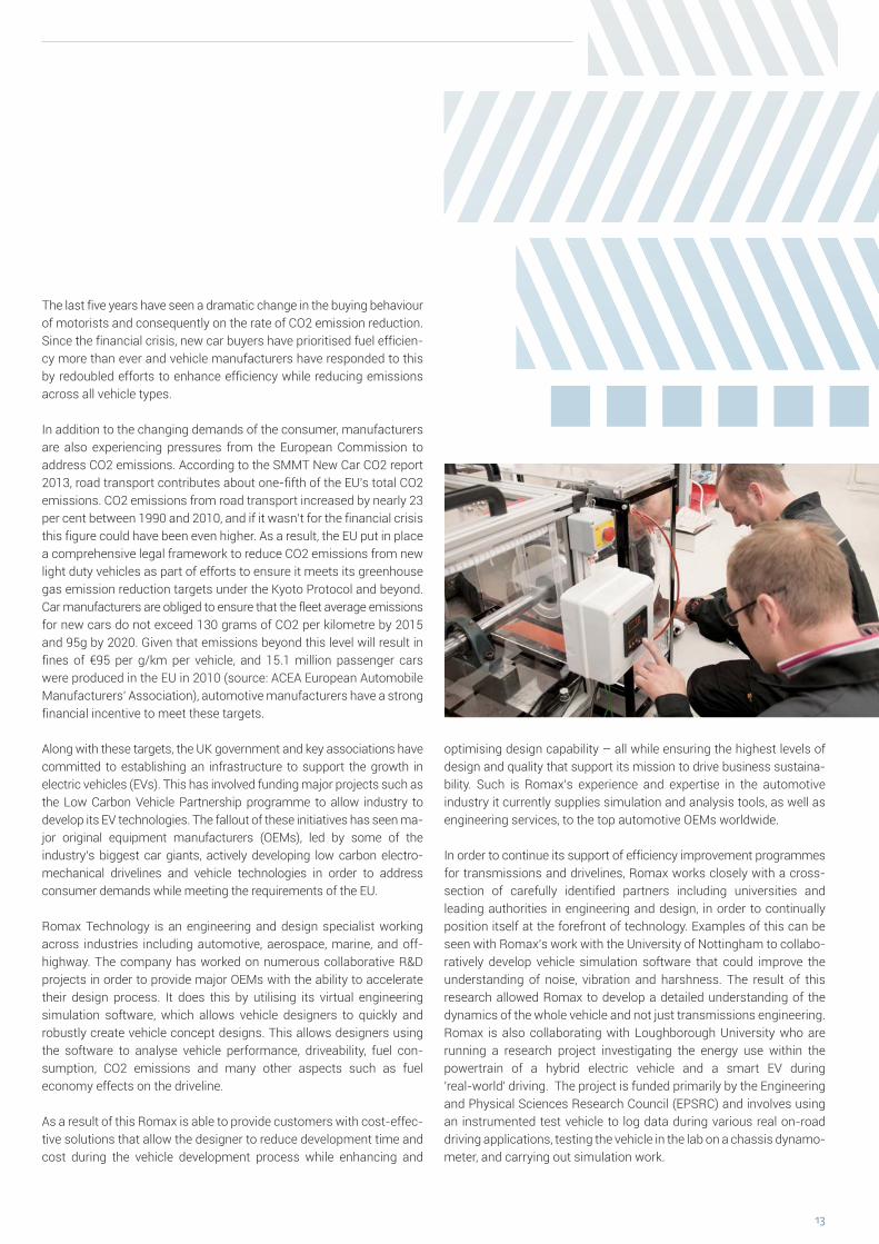
Romax Technology is an engineering and design specialist working across industries including automotive, aerospace, marine, and off-highway. The company has worked on numerous collaborative R&D projects in order to provide major OEMs with the ability to accelerate their design process. It does this by utilising its virtual engineering simulation software, which allows vehicle designers to quickly and robustly create vehicle concept designs. This allows designers using the software to analyse vehicle performance, driveability, fuel con-sumption, CO2 emissions and many other aspects such as fuel economy effects on the driveline.
As a result of this Romax is able to provide customers with cost-effec-tive solutions that allow the designer to reduce development time and cost during the vehicle development process while enhancing and
optimising design capability – all while ensuring the highest levels of design and quality that support its mission to drive business sustaina-bility. Such is Romax’s experience and expertise in the automotive industry it currently supplies simulation and analysis tools, as well as engineering services, to the top automotive OEMs worldwide.
In order to continue its support of efficiency improvement programmes for transmissions and drivelines, Romax works closely with a cross-section of carefully identified partners including universities and leading authorities in engineering and design, in order to continually position itself at the forefront of technology. Examples of this can be seen with Romax’s work with the University of Nottingham to collabo-ratively develop vehicle simulation software that could improve the understanding of noise, vibration and harshness. The result of this research allowed Romax to develop a detailed understanding of the dynamics of the whole vehicle and not just transmissions engineering. Romax is also collaborating with Loughborough University who are running a research project investigating the energy use within the powertrain of a hybrid electric vehicle and a smart EV during 'real-world' driving. The project is funded primarily by the Engineering and Physical Sciences Research Council (EPSRC) and involves using an instrumented test vehicle to log data during various real on-road driving applications, testing the vehicle in the lab on a chassis dynamo-meter, and carrying out simulation work.

14
About Romax Technology Limited Founded in 1989, Romax is a global
leader, providing solutions to design,
develop, deploy and monitor drivelines
for application in the automotive, heavy
equipment, aerospace and wind energy
sectors. Its portfolio ranges from drive-
train health management to conceptual
modelling and calculation right through
to whole system detailed design and
analysis. Romax has over 220 custo-
mers worldwide, including the majority
of OEMs across the transport and wind
industries. It has an investment partner-
ship with Moonray Investors, part of
Fidelity International, and has won a
number of industry awards, including
two Queens Awards for Enterprise in
International Trade. Romax is head-
quartered in Nottingham, United King-
dom and operates through 12 offi ces
globally. For more information, visit
www.romaxtech.com.
Press contacts:
Mirelle Ball BA (Hons), ACIM
Corporate Communications Manager
Tel: +44 (0) 115 951 8870
Web: www.romaxtech.com
Email: [email protected]
Nick Bird
Spreckley Partners Ltd
Tel: +44 (0)207 388 9988
Email: [email protected]
Most recently, Romax has been involved in a collaborative project alongside a number of automotive companies, aimed at looking at the simulation and optimisation of a highly integrated EV drivetrain. The focus of the project for Romax is to develop an electric vehicle drive-train system with a highly integrated electric machine and transmission design. This will include furthering the integration of the gearbox design as well as revolutionising EV powering, with the aim of achieving up to 50% cost reduction for manufacturers. The three-year project will look at innovating the driveline components and the early analysis of effici-ency, noise, and vibration through whole-system simulation, amongst other focuses such as housing integration, cooling lubrication, and power electronics.
The design space within the hybrid and EV vehicles market is incredibly vast, with many possible drivetrain configurations ranging from pure electric to conventional vehicles powered by internal combustion engines.
Romax believes in the need for whole-system rapid analysis of a large number of candidate concept designs earlier on in the development cycle, in order to free design engineers to investigate competing solu-tions at the very earliest stages. Changes at concept design stage are easier to implement and less costly than later on in the design process, and allow the designers freedom for creativity within the design process.
These ideals demonstrate Romax’s desire to drive next-generation technology development across the hybrid and EV automotive markets. In light of increased legislation and consumer demands a greater emphasis is being placed on addressing efficiency across driveline technology. Romax is meeting these challenges by providing software and design methodologies to ensure that the next generation of hybrids and EVs is as efficient and refined as their customers will surely expect.
www.romaxtech.com
15
Opportunities and ChallengersSince 2002, the automobile market in China is in historical boom. The market size that took developed countries hundred years to accumulate is easily achieved by China in ten years period. However, the expansion in volume is not accompanied with the improvement in quality. When the Chinese automobile industry is compared to the automobile industry in developed countries such as United State, Japan and Germany, signifi cant gap can be noticed, especially in the advance Automatic transmission sector.
In terms of market opportunity, we should look at carbon dioxide emission and consumer preference. China’s current carbon dioxide emission standard is 182 gram/km and the standard has to decline by 33% in order to reach the emission target of 120 gram/km by 2020. Looking at the technological level of China existing internal combusti-on engines and accessibility of related technology, where the engine technology contributed 40gram/km to carbon dioxide emission, methods such as improvement of Automatic transmission technology and etc. will be essential. On the consumer preference side, traffi c jams and increasingly complex road condition, coupled with increasing number of non-professional drivers push the market demand for Automatic transmission vehicle. At the same time, after ten years of rapid continuous growth, Chinese automobile market is gradually shifting from fi rst time purchase market to second time purchase market. Instead of just searching for a vehicle, Chinese consumers are
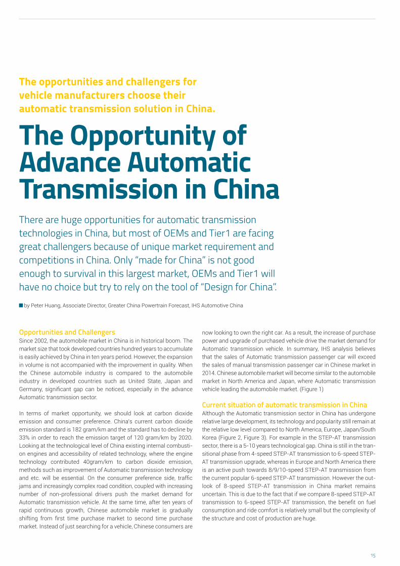
The opportunities and challengers for vehicle manufacturers choose their automatic transmission solution in China.
The Opportunity of Advance Automatic Transmission in ChinaThere are huge opportunities for automatic transmission technologies in China, but most of OEMs and Tier1 are facing great challengers because of unique market requirement and competitions in China. Only “made for China” is not good enough to survival in this largest market, OEMs and Tier1 will have no choice but try to rely on the tool of “Design for China”.
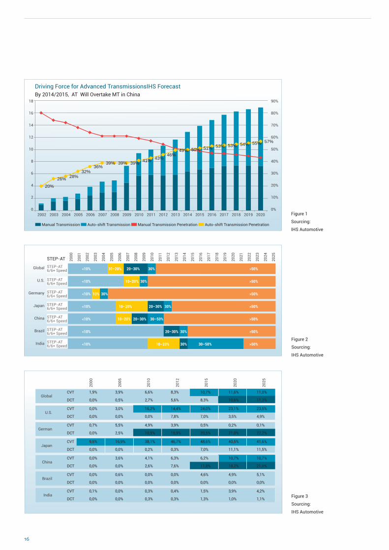
now looking to own the right car. As a result, the increase of purchase power and upgrade of purchased vehicle drive the market demand for Automatic transmission vehicle. In summary, IHS analysis believes that the sales of Automatic transmission passenger car will exceed the sales of manual transmission passenger car in Chinese market in 2014. Chinese automobile market will become similar to the automobile market in North America and Japan, where Automatic transmission vehicle leading the automobile market. (Figure 1)
Current situation of automatic transmission in ChinaAlthough the Automatic transmission sector in China has undergone relative large development, its technology and popularity still remain at the relative low level compared to North America, Europe, Japan/South Korea (Figure 2, Figure 3). For example in the STEP-AT transmission sector, there is a 5-10 years technological gap. China is still in the tran-sitional phase from 4-speed STEP-AT transmission to 6-speed STEP-AT transmission upgrade, whereas in Europe and North America there is an active push towards 8/9/10-speed STEP-AT transmission from the current popular 6-speed STEP-AT transmission. However the out-look of 8-speed STEP-AT transmission in China market remains uncertain. This is due to the fact that if we compare 8-speed STEP-AT transmission to 6-speed STEP-AT transmission, the benefi t on fuel consumption and ride comfort is relatively small but the complexity of the structure and cost of production are huge.
by Peter Huang, Associate Director, Greater China Powertrain Forecast, IHS Automotive China
16
20% 26% 28%
32% 36%
39% 39% 39% 41% 43% 46%
49% 50% 51% 53% 53% 54% 55% 57%
Driving Force for Advanced TransmissionsIHS Forecast By 2014/2015, AT Will Overtake MT in China
2002 2003 2004 2005 2006 2007 2008 2009 2010 2011 2012 2013 2014 2015 2016 2017 2018 2019 2020
18
16
14
12
10
8
6
4
2
0
90%
80%
70%
60%
50%
40%
30%
20%
10%
0%
Manual Transmission Auto-shift Transmission Manual Transmission Penetration Auto-shift Transmission Penetration
Figure 1
Sourcing:
IHS Automotive
STAP-AT6/6+ Speed
STAP-AT6/6+ Speed
y STAP-AT6/6+ Speed
STAP-AT6/6+ Speed
STAP-AT6/6+ Speed
STAP-AT6/6+ Speed
STAP-AT6/6+ Speed
2000
2001
2002
2003
2004
2005
2006
2007
2008
2009
2010
2011
2012
2013
2014
2015
2016
2017
2018
2019
2020
2021
2022
2023
2024
2025
Global
U.S.
Germany
Japan
China
Brazil
India
STEP-AT
STEP-AT6/6+ Speed
STEP-AT6/6+ Speed
STEP-AT6/6+ Speed
STEP-AT6/6+ Speed
STEP-AT6/6+ Speed
STEP-AT6/6+ Speed
STEP-AT6/6+ Speed
<10% 10–20% 20–30% 30% >50%
<10% 10–20% 30% >50%
<10% 10% 30% >50%
<10% 10–20% 20–30% 30% >50%
<10% 10–20% 20–30% 30–50% >50%
<10% 20–30% 30% >50%
<10% 10–20% 30% 30–50% >50%
2000
2005
2010
2012
2015
2020
2025
Global
U.S.
German
Japan
China
Brazil
India
CVT 1,9% 3,9% 6,6% 8,3% 10,7% 11,6% 11,8%
DCT 0,0% 0,5% 2,7% 5,6% 8,3% 10,6% 11,3%
CVT 0,0% 3,0% 16,2% 14,4% 24,0% 23,1% 23,5%
DCT 0,0% 0,0% 0,0% 7,8% 7,0% 3,5% 4,9%
CVT 0,7% 5,5% 4,9% 3,9% 0,5% 0,2% 0,1%
DCT 0,0% 2,5% 10,9% 15,9% 20,5% 21,0% 22,2%
CVT 0,1% 0,0% 0,3% 0,4% 1,5% 3,9% 4,2%
DCT 0,0% 0,0% 0,3% 0,3% 1,3% 1,0% 1,1%
CVT 0,0% 0,6% 0,0% 0,0% 4,6% 4,9% 5,1%
DCT 0,0% 0,0% 0,0% 0,0% 0,0% 0,0% 0,0%
CVT 0,0% 3,6% 4,1% 6,3% 6,2% 10,7% 10,7%
DCT 0,0% 0,0% 2,6% 7,6% 11,8% 18,2% 21,0%
CVT 9,5% 16,9% 38,1% 46,7% 48,6% 40,5% 41,6%
DCT 0,0% 0,0% 0,2% 0,3% 7,0% 11,1% 11,5%
Figure 2
Sourcing:
IHS Automotive
Figure 3
Sourcing:
IHS Automotive

17
China is rapidly catching up with Europe in dual-clutch Automatic transmission (DCT) sector. Under the Volkswagen’s active promotion, DCT’s market share in China has already exceeded North America and Japan, trailing only Europe. With Shanghai Automobile (SAIC), FAW Cars, and other domestic vehicle manufacturers began to produce and market dual- clutch Automatic transmission equipped models, DCT’s market share will increase signifi cantly in the future. On the other hand, in the Japanese companies dominated Continuous Variable Transmission (CVT) sector, the market share is relatively small due to the diffi culties and uncertainties of Japanese automobile companies in Chinese market. Despite some Chinese domestic vehicle manufac-turers have expressed deep interest in CVT, the domestic CVT produc-tion is unable to satisfy commercialized large volume production in terms of reliability and uniformity while international CVT production is limited by parent company and unable to supply to domestic Chinese domestic vehicle manufacturers, this resulted in the CVT becoming an exclusive product of Japanese automobile companies with limited increase in market share.
Not only “Made for China”, but also “Design for China”As the Chinese market continues to grow, so does the active local expansion of the global mainstream automobile companies and transmission manufacturing companies. Since China is geographically vast and regionally diverse, there is a signifi cant difference in the road conditions in different areas. Freezing temperature in the north, scot-ching hot in the south, windy and sandy in the west, humidity in the southern east, rugged road in the mountainous region, high speed freeway network in the coastal area, traffi c jam in the large cities and smooth traffi c in the inland areas, such complex road conditions require any Automatic transmission to have wide range of adaptability. It is not hard therefore, to imagine the diffi culty in developing a reliable Auto matic transmission technology that can be applied to all the requirements of different regions in China. Apart from the geographical differences, the developer of Automatic transmission has to give special consideration to consumer habit. As the Chinese society just started to use automobile, consumer habit is still at early immature stage. Overloading, reckless driving and lack of proper maintenance are common habits. Therefore tolerance towards the mentioned abnormal behavioural has to be included in the Automatic transmission design. If a Japan or Germany developed product is brought directly into Chinese market, there is an unavoidable scenario where the product may be unsuitable. Therefore in the hope of gaining more market share under the rapid growing but ultra-competitive Chinese market, some automobile manufacturers and parts companies are gradually moving from „made for China“ to „designed for China“.
Many international automatic transmission manufacturers have auto-nomous control over Automatic transmission technology. This is found lacking in Chinese domestic vehicle manufacturers as they still lean towards external system suppliers’ support for Automatic trans-mission product at this stage. One reason is due to the highly expen-sive cost of development and product for advance Automatic trans-mission. It is very hard for one single enterprise to bear the risk and cost of production without any volume as basic foundation. The other reason lies with the weakness in technological expertise of Chinese
domestic vehicle manufacturers, where the manufacturers obtain competitive advantage through low cost imitation of foreign selling cars, instead of gaining core competency through research and develop-ment in engine system and etc. As domestic Automatic transmission producers lack the capability to produce advance Automatic trans-mission, Chinese domestic vehicle manufacturers rely mostly on international Automatic transmission producers as the core supplier of their Automatic transmission product (Figure 4). Looking into the future, Chinese domestic vehicle manufacturers will be invest more on the development and manufacturing capability of advance Automatic transmission. This has been done through various methods such as co-operation (Borg Warner and ten domestic enterprises set up joint venture company to produce DCT core components), joint venture (DongFeng Auto and Getrag set up joint venture to produce low torque DCT), acquisitions (Geely acquired DSI from Australia), and independent research to set up reliable development and manufacturing capability in advance Automatic transmission, in order to satisfy the installation demand of the vehicles.
Despite various diffi culties, multinational car manufacturers, internati-onal Automatic transmission manufacturer and domestic vehicle manufacturers are actively involved in the development and populari-zation of advance Automatic transmission technology. In the midst of progress, what the enterprise has to understand is that unlike the change from volume to quality that happened in the automobile industry over the past ten years, the push for advance Automatic transmission comes from technological upgrade and consumer demand. Therefore the deciding factor will no longer be investment in production capacity or accumulation in research and development, but rather breakthrough in core technology, key investment in production capability and inno-vation in business model. Basically it is in short, right resources on the right projects at the right timing, instead of wide spread investment with thin margin.
Volkswagen
General Motors
Hyundai
Toyota
Renault/Nissan
Chery
Geely
Great Wall
BYD
FAW
AMT <6AT 6AT DCT CVT >6AT
Manufactured by itself Out-sourcing In Planning
Top 5 JV & Local OEM(CY2012, Passenger Car Market]
0 1 2 3 Millions
2.62
1.44
1.34
0.81
0.80
0.53
0.49
0.49
0.46
0.25
Figure 4 Sourcing: IHS Automotive

18
Application of Drivetrain Components on Different Markets
Market-specific Dimensioning of Drivetrain Components The customer operation reveals market-specific distinctions concerning load spectra. Therefore different markets demand different load assumptions within the development process.
by M.Sc. Lin Li, M.Sc. Mark Schudeleit and Prof. Dr Ferit Küçükay, TU Braunschweig, Institute of Automotive Engineering (IAE)
The 3D methodA prediction of the expected loads on different markets in an early stage of development is a key enabler for frontloading. To have a precise prediction of the load with regard to a specific market, road measurements are necessary. The IAE (Institute of Automotive Engi-neering) has carried out extensive measurements and experiments (by now about 1.5 million kilometers) on different types of driving environments, loads of driven vehicles and drivers in the US, China, Europe and Eastern Europe, resulting in a database which is incorpo-rated into the IAE’s so called 3D method. The 3D method divides the application areas of a vehicle systematically. This systematization is based on the influences on load and operation points of the conside-red vehicle components. Influences are classified to the three major axes of the 3D parameter space. As shown in figure 1, the major axes are “driver”, “driven vehicle” and “driving environs”, where the abbreviation 3D comes from.
18
The 3D parameter space
driv
en v
ehic
le
driving enviro
ns
driver
Countries of 3D measurements
trailerfullmiddlelight
highwaymountain
extra urbanurban
mildaverage
sporty
Figure 1 3D measurements based on the 3D method
19
a) Vehicle speed – [km/h]
0 20 40 60 80 100 120
20
16
12
8
4
0
time
ratio
[%]
v=31.4 km/h–
0 20 40 60 80 100 120
20
16
12
8
4
0
time
ratio
[%]
v=25.9 km/h–
b) Vehicle speed – [km/h]
1 2 3 4 5 6 7
30
20
10
0
time
ratio
[%]
Standstill9.3%
Standstill11.8% DE
CN
100 102 104 106
1
0.5
0.
-0.5
norm
. tra
nsm
issi
on in
put t
otqu
e [-
]
d) Number of load cycles per 1000 km [–]
DE
CN
2. gear
The 3D databaseDriving style is the central parameter of the 3D parameter space and, at the same time, the hardest to measure. Thus, the statistical spread of driver decisions and actions has to be collected – by means of measuring the 3D parameter space – to make working with the 3D method possible. For this purpose, vehicles are equipped with extensive measuring technology. Test persons are required to drive in different driving styles, which comply with their personal behavior, and with different types of load on different road types. Their actions and environ ment parameters are recorded by measuring technology and processed statistically afterwards, which has already resulted in an extensive database. The statistical database generated from the measurements is available for parameterizing simulation models by means of which the customer operation can be represented.
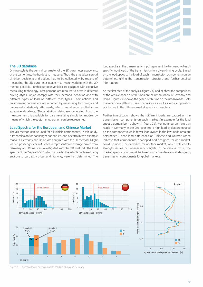
Load Spectra for the European and Chinese MarketThe 3D method can be used for all vehicle components. In this study, a transmission for passenger car and its load spectra in two example markets, Germany and China, are analyzed with the 3D method. A light loaded passenger car with each a representative average driver from Germany and China was investigated with the 3D method. The load spectra of the 7-speed-DCT, which is used in the vehicle on three driving environs: urban, extra urban and highway, were then determined. The
load spectra at the transmission input represent the frequency of each specific input load of the transmission in a given driving cycle. Based on the load spectra, the load of each transmission component can be determined, giving the transmission structure and further detailed information.
As the first step of the analysis, figure 2 a) and b) show the comparison of the vehicle speed distributions on the urban roads in Germany and China. Figure 2 c) shows the gear distribution on the urban roads. Both markets show different driver behaviors as well as vehicle operation points due to the different market specific characters.
Further investigation shows that different loads are caused on the transmission components on each market. An example for the load spectra comparison is shown in figure 2 d). For instance, on the urban roads in Germany in the 2nd gear, more high load cycles are caused on the components while fewer load cycles in the low loads area are determined. These load differences on Chinese and German roads indicate that components, developed and designed for one market, could be under- or oversized for another market, which will lead to strength issues or unnecessary weights in the vehicle. Thus, the market specific load must be taken into consideration at designing transmission components for global markets.
Figure 2 Comparison of driving on urban roads in China and Germany
c) gear [-]

20
ISO 26262 Process Certification The ISO 26262 standard for safety-related electrical and electronic systems in motor vehicles helps ensure functional safety and simplifies coordination during transmission development.
Development processes according to ISO 26262 simplify the development
of safe products across multiple companies. Since June 2013, the
development processes at Getrag have been certifi ed according to ISO 26262.
Copyright: SGS TÜV Saar
by Martin Seufert, Manager Safety & FMEA, Ralf Hettich, Functional Safety Manager and Dr Martin Leibbrandt, Manager Safety & FMEA GFT

21
Automatics on the riseManual transmissions still have a place in sporty and cost-critical appli cations, but automatics are becoming increasingly common. The transmission manufacturer Getrag expects that sales of dual clutch transmissions will increase from currently over one million units to more than twice that much in the year 2020. In consideration of incre-asingly ambitious CO2 targets, there is hardly any way around auto-matic and hybrid solutions. Dual clutch transmissions already on the market, such as Getrag’s 6DCT250, are already at least equivalent to manual transmissions in terms of effi ciency, and the next generation of dual clutch transmissions will offer superior fuel consumption.
Increasingly complex development processesHowever, the shift toward automatic transmissions also signifi cantly drives up the complexity of development processes. In contrast to manual transmissions, automatics must necessarily be viewed as part of the overall architecture of the vehicle. Electronics and software components control the interaction with the engine and possibly other components as well. The development process for transmissions is therefore embedded within an overall process that ideally follows the same rules at both OEMs and suppliers, especially when it involves the safety of products.
The methods for this are defi ned in ISO 26262. This standard descri-bes requirements for safety-related electrical and electronic systems in motor vehicles. In addition to safety requirements, it also specifi es process steps during development, similar to the V-model. The stan-dard also regulates the evaluation of functional safety. This takes place according to the “Automotive Safety Integrity Level (ASIL)” which defi nes the safety-relevance of malfunctions. This multilevel system (A to D) rates how frequently errors occur, how easily they can be over-come and how serious the consequences of a malfunction are. Based on this rating, corresponding requirements defi ned in the standard must be fulfi lled.
Getrag development follows ISO 26262Getrag began developing dual clutch transmissions according to ISO 26262 in 2007, even though the standard only went into effect in November 2011. A number of products have therefore already been assessed by TÜV or by our customers – such as the dual clutch trans-missions 7DCI700, 7DCL750 and 6DCT250. The processes (manage -ment processes, development processes and supporting processes) at Getrag have now also been certifi ed with regard to their compliance with ISO 26262: “Functional safety is truly implemented at Getrag,” says Martin Stock, project manager at SGS-TÜV Saar. All future dual clutch and hybrid transmissions will naturally also be developed accor-ding to the ISO 26262 standard, including the new 7DCT300 with wet clutches and on-demand control of the electrohydraulic and electro-mechanical actuators and the 6DCT150, which will bring the dual clutch transmission into the small car segment as of 2016.
According to their ASIL rating (C or D), dual clutch transmissions are critical vehicle components. The automated operation leaves open the possibility of malfunctions that the driver cannot influence or can only overcome with diffi culty. These include, for example, faulty shifting or clutch operations or moving in the wrong direction. The standard helps to classify such risks in a uniform way to support the defi nition of appropriate measures. As hybridisation gains ground, the number of such potential risks will grow still further – making it that much more important to practice reliable and safe development processes that are transparent to all parties.
Uniform standard for all partiesSuitable processes naturally existed to ensure product safety even before introduction of the standard, but ISO 26262 now offers considerable advantages for the collaboration between OEMs and suppliers. It esta-blishes a uniform standard for the entire vehicle, its subsystems and individual components. In this way, the standard assists in maintaining the transparency of development processes across various companies and development areas and fosters a shared safety culture. Thanks to the certifi ed functional safety process, the OEM can be confi dent that Getrag follows the rules of functional safety during development – which is additionally advantageous in matters of product liability.
Getrag has developed its dual clutch transmissions
according to ISO 26262 since 2007 – shown here is
the 6DCT250 with completely electromechanical actuation.
Copyright: Getrag
22
But What of the Humble Manual Transmission... The automotive industry/media has become very focused on the drive for newer dual clutch transmissions, and the development of automatics with an increasing number of forward speeds. But what about the humble manual transmission?
WorldwideToday, manual transmissions (MTs) are fitted in approximately half of all light duty, on-highway vehicles, built globally. Moreover, IHS Auto-motive forecasts that this share will not diminish significantly, over the next 7 years. Admittedly, the manual transmission is quite well deve-loped, but efforts are still being made to improve their mechanical efficiency, and their shift quality. This is particularly true of some of the older manual transmissions, which have been around for many years. A good example would be the 5-speed Ford (now Getrag-Ford) IB5, which was introduced back in 1995, but which is expected to continue in production past 2020 in some regions of the world. This highlights the much longer lifecycles for manual transmissions, which tend to experience evolutionary designs, rather than replacements by newer products.
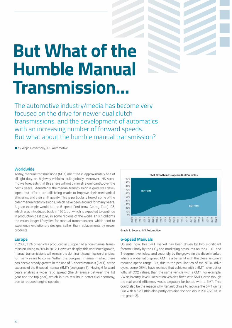
EuropeIn 2000, 13% of vehicles produced in Europe had a non-manual trans-mission, rising to 30% in 2012. However, despite this continued growth, manual transmissions will remain the dominant transmission of choice, for many years to come. Within the European manual market, there has been a steady growth in the use of 6-speed manuals (6MT), at the expense of the 5-speed manual (5MT) (see graph 1). Having 6 forward gears enables a wider ratio spread (the difference between the 1st gear and the top gear), which in turn results in better fuel economy, due to reduced engine speeds.
6-Speed ManualsUp until now, this 6MT market has been driven by two significant factors: Firstly by the CO2 and marketing pressures on the C-, D- and E-segment vehicles; and secondly, by the growth in the diesel market, where a wider ratio spread 6MT is a better fit with the diesel engine’s reduced speed range. But, due to the peculiarities of the NEDC drive cycle, some OEMs have realised that vehicles with a 5MT have better ‘official’ CO2 values, than the same vehicle with a 6MT. For example, VW sells entry-level BlueMotion vehicles fitted with 5MTs, even though the real world efficiency would arguably be better, with a 6MT. This could also be the reason why Renault chose to replace the 6MT on its Clio with a 5MT (this also partly explains the odd dip in 2012/2013, in the graph 2).
100%90%80%70%60%50%40%30%20%10%
0%
6MT Growth in European-Built Vehicles
2000
2001
2002
2003
2004
2005
2006
2007
2008
2009
2010
2011
2012
2013
2014
2015
2016
2017
2018
2019
2020
4MT/5MT
6MT/7MT
Graph 1. Source: IHS Automotive
by Wajih Hossenally, IHS Automotive

23
So, it could be argued that the penetration of 6MTs has been restricted by the NEDC, and there is no reason for this to change until the new WLTP (World Light Test Procedure) legislation is introduced, with its new test cycle. Although the WLTC (World Light Test Cycle) is still being discussed, IHS Automotive expects that this new globalised test cycle will take more account of the number of gears, in both manual and non-manual transmissions. In other words, it will be more closely related to the real world CO2 values, which the average driver will experience.This is likely to further contribute to the growth of 6-speed manuals.
Of course, the pressure from CO2 legislation will continue to push the use of 6MTs over 5MTs, in all but the smallest of gasoline applications. But it is a new trend in turbocharged ‘downsized’ gasoline engines, which will prompt most of the 6MT growth in the years to come. Like diesel engines, the combination of a 6MT with a turbocharged gasoline engine is a much better fit, than with a 5MT. If we define ‘small 6MTs’ as anything rated under 250N.m, then the IHS Automotive data shows volumes consumed in Europe of almost zero in 2000, rising to 1.1 million this year, and projected to grow to 3.6 million by 2020 (see graph 2).
Are the OEMs prepared for an increasing demand for ‘right sized’ 6-Speed Manuals?Most OEMs have at least one 6MT at their disposal, but many of these are rated at 250N.m and above. These are fine for the mid-size and larger applications, or those with higher torque diesel engines, but what about for smaller and lower torque vehicles?
Toyota was one of the early adopters of smaller 6MTs, with its EC60/BJ6 being used across most of its vehicle range. Of those vehicles built in Europe in 2013, 70% of the manuals are already 6-speed, with the 5MTs used only in the smallest Toyota Aygo. Volkswagen has the MQ200, in both 5-speed and 6-speed variants. Volkswagen is expected to ramp up their MQ200-6 volume, so that it eventually represents more than 60% of the total MQ200 volume. Fiat is also well prepared for such demand. Their C514-6 has been in production for many years now, at lower volumes, but will be ramped up significantly in the future.Renault has their lower torque TL4/TL8, which is manufactured at two plants in Europe, giving them the flexibility to increase volumes relatively easily.
Graph 2. Source: IHS Automotive
Mercedes-Benz has little need for smaller manuals in its rear-wheel-drive (RWD) applications, and has already moved over to a 6-speed manual in its front-wheel-drive (FWD) applications. It is interesting to note, that Mercedes-Benz will soon start to outsource the supply of RWD manual transmissions, for passenger car applications, in much the same way that BMW outsources transmissions. This will allow Mercedes-Benz to concentrate on its automatic transmission develop-ments.
GM has been manufacturing the 6-speed M20 for several years now, although it is quite large/heavy, as it shares a case with the higher rated M32. From late 2013 GM (China) will start production of the new M1x, which weighs just 37kg (dry) – much less than the existing M20.Getrag has already launched the 6MTT250 (B6), the 6MTT220 and the 6MTT350, which are the first 3 programs in a new modular family of 5- and 6-speed manual transmissions. These are for use primarily by Ford and BMW/Mini, although Mini has already phased out the use of 5-speed manuals. An additional 2 programs will be added to the family, in the next few years, which will result in the phasing out of the old Getrag-Ford IB5 5-speed manual.
One of the last OEMs to appreciate the need for a smaller 6MT is PSA. At present, their smallest 6MT is the MCM, rated at 300N.m. It is under-stood that PSA is now considering a new 6MT, called the MB6, from 2016/2017, which we expect to be rated at about 200N.m. However, if PSA decides not to develop and manufacture the MB6, it could buy in (or manufacture under licence) another transmission – the GM M1x being the most logical choice.
7-Speed ManualsNo discussion about the development of the manual transmission market would be complete, without some comments about the 7MT. At the moment, Porsche is using the ZF S7-70 in several of its sports cars, and Chevrolet is using the Tremec TR-6070 in its Corvette. In these cases, the extra gear is used like an old-fashioned overdrive, to reduce the engine speed (and hence CO2) when cruising at higher speeds. This trend may be seen in some other sports car applications, but is not expected to filter down into the mainstream market, any time soon. What we do expect, however, is the use of 7MTs in some panel vans, where the extra gear will be used as a crawler gear, below the existing 1st gear, to improve the launch experience when fully laden. IHS Automotive currently expects at least two OEMs to go down this route, in the next few years.
Wajih Hossenally is a Powertrain Analyst with IHS Automotive,
focussing on the European transmission market.
4,0
3,5
3,0
2,5
2,0
1,5
1,0
0,5
0,0
Small 6MTs Fitted in European-Built Vehicles
2000
2001
2002
2003
2004
2005
2006
2007
2008
2009
2010
2011
2012
2013
2014
2015
2016
2017
2018
2019
2020
Mill
ions

24
The mass market is very cost-sensitive. As a result, design engineers of modern compact and mid-size cars are faced with a constant trade-off: not only do their vehicles have to offer an increasingly better driving experience with greater comfort, these cars are also expected not to strain the buyers‘ wallets in two respects – i.e. the purchase price as well as the operating costs, which primarily entail the expenses at the gas pump. What does this mean for the drive train?
In engine construction, downsizing and downspeeding are the methods of choice – so long as they do not result in diminished power. After all, saving fuel is particularly fun when you can still step on it. The logical consequence is slow-speed three- or even two-cylinder engines with high torque. The downstream drive train must cope with this rough-running new power source. At the same time, the entire drive train must satisfy an indispen sable trifecta: lightweight construction, incre-ased effi ciency and cost neutrality.
As compact as possibleThe transmissions of the future must therefore be able to handle rough engine operation, be even lighter, and have lower effi ciency losses – all without price increases. Developers and designers notably meet this requirements profi le with a smaller complete system, minimal oil quantity for lubrication, and lighter-weight components. Assuming the current system architecture as a given, this transmission downsizing nonetheless has clear limitations: to be able to transmit the necessary torque and offer adequate shifting comfort, a particular minimum size must be met.
Apart from some detail improvements, almost all series-produced systems, especially in the synchronizer fi eld, operate based on the ori-ginal BorgWarner principle. During times where automobile producers
HOERBIGER CompactLINE
The Synchronizer for the Drive Train of the Future
and transmission manufacturers scrutinize every single component in the quest for downsizing potential, this functional principle is reaching its limits.
Outer cone synchronizer made of metal-formed partsWith this in mind, HOERBIGER has reconsidered an alternative synchro-nization principle, the outer cone synchronizer. This concept has been around since the 1970s. Several manufacturers dabbled in this special design of the transmission synchronizer in the past. Given the high manu-facturing costs, though, none of the projects reached the production stage. Complicated contours necessitate complex machining steps, resulting in a cost-intensive and uneconomical production process.
This has changed with the HOERBIGER CompactLINE: HOERBIGER has been manufacturing synchronizer rings using only metal forming technology since 1996. HOERBIGER has now applied the know-how gathered in the past decade and a half to the overall synchronizer system. The CompactLINE has made an outer cone synchronizer available that is not only compact and effi cient, but also competitive to produce. HOERBIGER uses almost 100 percent of metal-formed parts for the CompactLINE, creating an outstanding cost structure – especially for high-volume applications.
Up with shifting comfort – Down with space requirementsCompared to standard synchronizers, the outer friction cone of the CompactLINE provides up to a 20 percent increase in friction torque. In practice, this means best-in-class shifting comfort while maintaining a high level of comfort in a considerably reduced installation space. The CompactLINE rounds out the HOERBIGER synchronizer portfolio for small transmissions with up to 200 Nm input torque.
In the lower and mid-range vehicle segments, the end customer does not expect cutting-edge technology when it comes to the drive train. Here, conventionally driven vehicles which stand out with their fuel and cost efficiency are in demand.
by Ottmar Back, Head of Product Management, HOERBIGER Antriebstechnik GmbH

25
The CompactLINE achieves weight savings in two respects: not only is the synchronizer itself up to 35 percent lighter than standard products, but its compact design also allows a smaller complete transmission system. As a result, the transmission housing and the necessary oil quantities can shrink along with the CompactLINE. The elimination of the solid sliding sleeve and active lifting of the synchronizer rings assure moment of inertia that is approximately 25 percent lower as well as reduced drag loss. This signifi cantly increases transmission effi ciency.
Efficient solution for the downsized drive trainThe design of the HOERBIGER CompactLINE assures that all the com-ponents are guided in the prescribed manner and prevents NVH prob-lems such as rattling due to vibrations from loose parts. This is an important acceptance criterion for customers – especially in connec-tion with downsized engines.
The advantages of the CompactLINE benefi t not only classic manual transmissions. Even modern double-clutch transmissions couldn‘t shift gears without synchronizers. An additional interesting fi eld of application includes automated manual transmissions (AMTs). Gears are changed automatically in AMTs, and the clutch is also operated by an actuator; there is no clutch pedal.
This makes AMTs a cost-effective alternative to dual-clutch and torque-converter transmissions and they are increasingly gaining in popularity, notably in the emerging markets. The drawback is that the automatic gear change is usually not as responsive as that of an experienced driver. The friction torque of the Compact-LINE, which is the highest in its class, assures minimized syn-chronization times. As a result, shifting through gears can be done more quickly and the clutch need not remain disengaged as long. This lowers the effect of interruption of torque flow, which has been the object of frequent criticism in AMTs.
An understanding of the system as the basis for implementation in productionThe functional principle of the CompactLINE can revolutionize trans-mission design: HOERBIGER not only integrated the functions of the traditional synchronizer into an entirely new principle, but also desig-ned the necessary production processes. In addition, as the largest independent manufacturer of complete synchronizer systems in the world, HOERBIGER understands the interactions of the components in
About HOERBIGERHOERBIGER is a global leader in the fi elds of compression technology, automati-
on technology, and drive technology. In 2012, its 6,700 employees achieved sales
of approximately 1.06 billion euros. The focal points of its business activities
include key components and services for compressors, gas-powered engines,
and turbomachinery, hydraulic systems and piezo technology for vehicles and
machine tools, as well as components and systems for shift and clutch opera-
tions in vehicle drive trains of all kinds. Through innovations in attractive techno-
logical niche markets, the HOERBIGER Group sets standards and creates unique
selling propositions with long-term benefi t for the customer.
s-he g-
esthe
ec
l
e ng. eeen
mb-an c-c
n
Figure 1: The functional principle of the HOERBIGER CompactLINE allows
elimination of the solid sliding sleeve. Photo: HOERBIGER
Figure 2: The diameter of the friction ring, which is larger compared to
standard synchronizers, provides up to a 20 percent increase in friction torque.
Photo: HOERBIGER
the entire system and is able to support OEMs and transmission manufacturers in modernizing their transmission architecture in order to utilize the advantages of the CompactLINE.
Following intensive development work, the presentation before the trade audience was now the fi rst step toward implementation in production. The next step includes driving demonstrations for the customer in a production vehicle.
Figure 1
Figure 2

26
Reduced investment costs, short delivery times
Serial Production of Transmission Test Stands
Project-neutral transmission test stand platformThe ongoing reduction of consumption and emission values are driving new developments in powertrains, and gearbox design has kept pace with these advances. To cut the cost of investment in transmission testing for their customers, the teamtechnik Group, international experts in the automation of assembly and function testing, is now offering a revolutionary concept: series production of standard trans-mission test stands. The idea is based on the project-neutral Compact Drive machine which can be quickly adapted to specifi c customer requirements. This basic machine is so flexible that proven standar-dized machine-assembly modules can be combined effi ciently with customer-specifi c systems.
Comprehensive modular designBased in the southern German city of Freiberg, teamtechnik has been making test benches for all types of transmissions for the last 25 years. However, the 1990s saw the company depart from traditional custo-mized machine engineering and start to focus on modular structures. This was an extremely unusual approach to making transmission test stands at that time, as Michael Weis, COO and Head of the Automotive Business Division at teamtechnik, said: "No one else in this sector was thinking about standardization. Building transmission test stands meant customized construction." Today, teamtechnik has a compre-hensive, modular system for producing standard transmission test stands, complemented by ample product and process expertise and by test software which can be operated without any traditional programming knowledge.
Solutions from R&D to mass productionFor the second time, teamtechnik is now announcing a new era in the manufacture of transmission test stands. "We can offer serial production of standard transmission test stands without compromising on quality," said Michael Weis. "The test stands are adapted from the basic struc-ture to the relevant transmission type in the application engineering phase." teamtechnik keeps a stock of the product-neutral components for the test stand, which it manufactures in advance. Consequently, the time to delivery only varies due to the amount of application engi-neering required to adapt the test stand to the customer's specifi c transmission type. The result is a turnkey test stand that is ready much more quickly than is usual in the market. teamtechnik promises its customers in the automotive industry delivery times of up to six months, and also lower investment costs. "At the same time, the in-vestment costs fall over the whole production cycle," said Michael Weis. teamtechnik offers economical and technologically well-thought-out solutions right from development and then on to pre-series and series testing. This allows, for example, greater maturity at start of production with few changes during series production.
teamtechnik is launching scheduled production of transmission test stands and supplies customer-specific systems in just six months.
Ready to be adapted to customer-specifi c requirements: modular test stand design.
Input-drive, output and control modules are product-neutral and standardized.
es
by Thomas Hoffmann, Head of Transmission Test SystemandEdwin Raad, Head of Sales Automotive,teamtechnik Maschinen und Anlagen GmbH

27
Test sequences using drag-and-dropteamtechnik has developed the teamsoft.TEST software to optimize test sequences quickly and flexibly. It can be used on the development test stands, at the pre-series stage, and in series production. The modular software was developed in house. It breaks testing down into basic functions, such as time and interface functions, input/output func-tions, and triggers, which are already grouped into test command sequences. The test modules can be confi gured and combined as required, which allows them to be re-used for different testing tasks. The test sequences are executed on a National Instruments LabVIEW runtime system. According to Michael Weis, the application is impres-sively simple to use. "Users do not need specialist programming knowledge. They can create new sequences intuitively, using drag-and-drop, and work from any web-enabled end device."
Stefan Rosskopf, CEO of teamtechnik Group, wants to put teamtechnik ahead in the international market by systematically expanding its engineering expertise and production capacity for transmission test systems. "We are endeavoring to achieve global market leadership in passenger vehicle transmission testing by mid-2014," he said. team-technik has its own production sites in Germany, Poland, China, and the USA, and a dense service network throughout the world. It works for many major companies in the automotive market, and its relation-ship with most of them goes back many years. Stefan Rosskopf is fi rmly of the opinion that the company's high level of skill and ability results from these close and lengthy collaborations with its custo-mers: "Our transmission test stands are used to test simple power takeoff units as well as complex modern automatic transmissions, double-clutch transmissions, and hybrid transmissions."
COMPACT DRIVE transmission test stand tests all passenger vehicle transmissions
Test software teamsoft.TEST enables easy and quick optimization of test sequences - without specialist programming knowledge
Contact: teamtechnik Maschinen und Anlagen GmbH | Planckstr. 4, 71691 Freiberg/Neckar, Germany
Thomas Hoffmann, Head of Transmission Test Systems | Phone: +49 (0) 71 41/70 03–3 05 | Email: [email protected]
Edwin Raad, Head of Sales Automotive | Phone: +49 (0) 71 41/70 03–1 78 | Email: [email protected]

28
Transmission design for very high input speeds
Increasing Transmission SpeedsAs electrical powertrains mature a trend for increased rotational speed is emerging that will challenge current transmission designs.
by George Scott CEng, Principal Engineer, Drive System Design
The need for high speed transmissionsWhen driven by a conventional piston engine, the input shaft of a typical road vehicle transmission rotates at speeds well below 10,000rpm. In contrast, electric motors rotate at much higher speeds, so transmissions for electric vehicles must accommodate these higher speeds on their input side. To improve efficiency, motor speeds are increasing further, with up to 20,000 rpm becoming a reality, representing a doubling or tripling of the usual transmission input shaft speed. Higher input speeds affect the transmission design in several ways, both at com-ponent and system level, requiring considered solutions that reflect the change in operating conditions.
Component selection for volume productionIncreasing the input speed has moved the operating requirements signi ficantly outside the rated specification of many common compo-nents used in the series production of geared power transmission systems, such as seals and bearings. The specifications are often expressed as a limiting value of equivalent linear speed, combining the effects of diameter and rpm, but restricting shaft diameter to reduce the linear speed is rarely a realistic option because of the torque load.Bearing speed limits are usually driven by sliding contact between the various elements with extended performance versions available at extra cost. A balance often has to be made between load capacity and speed capability. For seals, wear-resistant materials or non-contac-ting designs can be considered. Even the best materials only extend
the speed range by around 25% however. To accommodate two or three times the speed clearly requires more significant design change.In many cases, specialist solutions have been developed for other ap-plications but typically come at a cost that is not realistic for automo-tive use in large volume. Economies of scale as electric and hybrid vehicle technology achieves a greater share of the volume market must be realised to facilitate the use of these solutions.
System level challenges for durability and efficiencyThere are further considerations at a system level such as the need to incorporate additional meshes in the driveline, to achieve the necessa-ry speed reduction, which has implications for overall efficiency and direction of rotation. Comprehensive analysis is required to identify the trade-offs between the lower torque and reduced component weight associated with high rotational speed, versus the increased parasitic losses, before an optimum layout can be selected.
Transmission lubrication regimes are particularly sensitive to rotatio-nal speed, presenting significant challenges with regard to maintai-ning lubrication in critical areas. It may be necessary to introduce pressurised lubrication in some locations to overcome centrifugal ac-tion. Energy losses at the input shaft due to drag and churning become much more significant with a high speed, low torque system. Lubri-cant selection and additive engineering is also key to ensuring system reliability and efficiency.

29
Electric vehicle transmissions are being challenged with increased input speeds
© 2013 Drive System Design
Design solutions for high input speed transmissionsTo facilitate the smooth introduction of transmissions for high speed motors into larger volume production, in a cost effective manner, requires several stages of analysis and simulation to support the evolution of the optimum mechanical layout. In addition to efficiency considerations, the increase in reflected inertias due to higher input speeds must be considered, the implications for gear geometry and the subtleties of integrating a high-speed motor into the transmission.
The transmission architecture must also consider inertia from the outset both in terms of upstream and downstream. Multiple speed transmissions will have greater demands placed on their shift elements by increased inertias and higher speeds. Motor control may be able to support gear shift events however the transmission must be designed in close cooperation. Downstream high overall ratios lead to high reflec-ted inertias where we have seen issues with ABS/ESP interaction.
Gear sizing and geometry will differ from a conventional transmission, with gears closer to the input, where speeds are higher, needing lower module, shorter teeth to minimise sliding at the mesh. The challenge here is to ensure sufficient contact ratio to minimise noise generation and maximise tooth strength by increasing face width. Gear accuracy must also be considered and improved due to the dynamic loads generated as a result being amplified at higher speeds.
Advances in low friction coatings and process can be employed to assist in a number of areas including gear contact surfaces and potentially bearings and sealing surfaces. Interfaces between the transmission and other components operating at high speed must be carefully con-sidered. High speed motor bearings are unlikely to accommodate additional loads exerted by the transmission. Components such as quill shafts and flex plates can assist in this but shaft whirl and centrifu-gal loading must be considered.
Transmission design for very high input speeds requires a complete system approach coupled with the adoption of appropriate emerging technology solutions. Concurrent design and analysis can help to ensure that all aspects of this challenging application are addressed and viable solutions created. Drive System Design is actively engaged in research and design activities aimed at solving these challenges, using splash lubrication upto 20,000rpm and forced lubrication in an application running at 50,000 rpm.

30
Efficiency Boost with Two-Drive-Transmission (TDT) for Range Extender Vehicles
Range is currently one of the most crucial issues of pure electric vehicles. Thus, conventional internal com-bustion engines (ICE) are used as range extenders to allow long distance driving. A straight-forward ap-proach is to directly connect the ICE with an e-machine. However, this series hybrid configuration does not show an optimal efficiency according to the double conversion of energy. Usually, a parallel hybrid configuration is much more efficient. Hence, the challenge is to find a powertrain configuration with high efficiency in both pure electric and hybrid mode.
In order to follow this objective, the Institute for Mechatronic Systems (IMS) is doing research on powertrain configurations using the approach of the so-called Two-Drive-Transmission (TDT). The TDT, for which two different layouts are shown in Fig. 1, is an electric powertrain unit with two automated transmission parts based on layshaft technology. One of the main ideas is machine downsizing by using two small e-machines instead of one big machine. For most frequently occurring partial load driving, the utilization of one small e-machine is higher and, depending on the machine type, operating points can be shifted to higher efficiency. Multiple transmission speeds can further increase efficiency and, in addition, enable an increase of the launch torque as well as high maximum speeds. To avoid traction force interruption during shifting, the e-machine connected with the respective not shifted transmission part is used to realize a torque fill.
Figure 1 Different TDT layouts:
identical transmission parts (left)
and integrated parking lock (right).
by Stephan Rinderknecht, Torben Meier and Ruben König, Institute for Mechatronic Systems in Mechanical Engineering (IMS), TU Darmstadt

31
Figure 2 Simulation results for different powertrains in NEDC.
The benefits of two downsized machines and the multispeed approach are faced by the additional effort for two e-machines plus periphery. On the other hand, hybrid transmission systems allowing parallel as well as series hybrid mode, do need two e-machines. Thus, the powertrain can easily be upgraded to a range extender system with very efficient electric operation, whereat at least two transmission speeds should be available in the transmission part with the ICE. The ICE can use the speeds of the respective transmission part for parallel mode or operate as series hybrid when shifted to neutral. If the ICE is attached to the layshaft, the e-machines can run on a beneficial higher speed level. With the second layout shown in Fig. 1, even an integrated parking lock can be realized by engaging two speeds of one transmission part at the same time and thus blocking the transmission. For further efficiency improvement, the clutch of the ICE (C5) could be executed as a dog clutch same as for the speed gears (C1 to C4).
While driving, the parallel hybrid mode is normally more efficient compared to the series hybrid mode and thus preferred. Nevertheless, the availability of a series hybrid mode allows e.g. vehicle launch without a drive-away clutch for the ICE even with empty battery.
The powertrain data in Tab. 1 and corresponding simulation results in Fig. 2 emphasize the benefits of the TDT concept. Simulations for the New European Drive Cycle (NEDC) using general data of the Opel Ampera are first performed with a single machine and single speed transmission (1EM1SP) as pure electric vehicle and then with the TDT (two identical e-machines as well as two identical two speed transmission parts) including gasoline ICE.
E-Machine (s) ICE Transmission Pure Electric Driving
PEM, max TEM, max nEM, max PICE, max i1,tot i2,tot t0-100, ED Vmax, ED Twheel, max, ED
in kW in Nm in 1/min in kW – – in s in km/h in Nm
1 1x10² 1x195 12.000 – 9 – 11,4 165 1.755
2 2x51 2x98 12.000 57 14 7 9,3 212 2.744
3 2x42 2x80 12.000 57 14 7 11,4 208 2.240
1EM1SP-102 13,9
TDT-102 11,9
TDT-84 11,7
0 5 10 15Pure Electric Energy Consumptionin kWh/100km
1EM1SP-102
TDT-102 4,36
TDT-84 4,10
0 1 2 3 4Fuel Consumption for Low Charge Batteryin l/100 km
Comparing the first two simulation results where both approaches have an identical overall electric drive power of 102 kW, it can be seen, that the TDT shows both significant reduction of pure electric energy con-sumption of around 14% and significant improvement in pure electric driving performance. In the third simulation, the TDT is further downsized to come up with the same acceleration performance as the 1EM1SP. With an overall electric drive power of 84 kW the TDT can reduce energy consumption by another 2% (electric) respectively 6% (fuel) still having a higher pure electric launch torque and top speed capability compared with the 1EM1SP. In conclusion, the TDT multispeed concept with two e-machines shows very high potential to reduce energy consumption. In addition, the multispeed approach increases performance or allows further downsizing respectively. Finally, pure electric range can be increased for the same battery size and as combined hybrid, a highly efficient and flexible range extender operation can be performed.
Table 1 Simulation data for 1EM1SP-102 (1), TDT-102 (2) and TDT-84 (3).

32
SKF collaborates with Protean Electric in a strategic partnership to develop advanced drive solutions for the hybrid and electric vehicle markets.
SKF Venture into In-wheel Motor Technology SKF continuously works in close cooperation with customers and engineering companies to develop new technologies and innovative solutions. In this partnership SKF develops unique wheel hub bearing and sealing solutions specifically for the Protean Drive™ PD18 in-wheel motor. The hub bearing, through the camber stiffness it provides, has a significant influence on the performance of the in-wheel motor by controlling the motor’s air-gap.
by Mark Verbakel, Team Leader Project Management, SKF

33
Challenges of in-wheel motorsIn-wheel motors promise more space and less weight by eliminating driveline components, better vehicle control by torque vectoring, faster acceleration and better fuel economy. The technology however, also deals with unique challenges such as packaging enough power into a small space and a reliable operation in a hostile in-wheel motor environ ment of vibration, shock loads, contamination etc..
Protean ElectricUS-based Protean Electric is a leading clean technology company that designs, develops and manufactures the Protean Drive™, a fully integ-rated, in-wheel motor, direct-drive solution for electric hybrid vehicles.Protean’s in-wheel motors are leading in terms of torque and power density among today’s electric propulsion systems. Each Protean Drive™ in-wheel motor can deliver 81 kW (110 hp) and 800 Nm (590 lb-ft), yet weighs only 31 kg (68 lbs.) and is sized to fit within the space of a conventional 18- to 24-inch road wheel.
Strategic PartnershipSKF has signed a strategic partnership agreement with Protean Electric where SKF will supply its expertise and advanced automotive solutions for Protean’s in-wheel electric drive for the hybrid and electric vehicle markets.
Controlling the air gapPackaging enough power into the small space envelope requires the motor’s air gap to run at a large diameter, be long in axial direction, and to be thin. Protean’s inside-out design, where the rotor runs on the outside of the stator, maximizes the diameter of the air gap. The other two performance drivers, i.e. a long, and thin air gap depend on the mechanical stiffness of the system in general, and the camber stiffness of the bearing solution in particular.
SKF’s high-stiffness bearing solution that is under development for the Protean Drive™, allows for smaller clearances, which in turn enables a longer and thinner air gap. This has a direct impact on the torque capacity and thus the power of the system. SKF relies on its extensive knowledge and expertise of wheel hub bearing solutions to maximise the bearing stiffness within the given packaging envelope, and illustrates how SKF supports its partners in innovation.
Keeping the elements outSealing off the in-wheel motor’s internal space against external elements is another key challenge where SKF supports with its knowledge and expertise in sealing solutions. This dynamic seal needs to perform under the full operating envelope of temperatures and speeds over the life-time of the vehicle. This case presents a particular challenge in that the motor cavity is sealed at a large diameter, which results in a high speed at which the seal runs against its counter face.
In meeting this challenge, SKF and Protean combine their knowledge of materials, manufacturing methods, testing and state of the art simulation tools.
SKF BeyondZero“Aligned with our SKF BeyondZero strategy, SKF is committed to deve-loping technology to support the electric and hybrid vehicle market to further reduce the carbon footprint. Combining our engineering know-ledge with Protean’s expertise for in-wheel motors will be an excellent way to develop this market,” says Tryggve Sthen, President, SKF Auto-motive.
Contact: [email protected]
StatorWheel Bearing
Rotor
Conventional Alloy Wheel
Coils & Power Electronics/Micro Inverters
Vehicle Suspensions

34
Development TargetsIt is a vehicle for the future and sets new benchmarks for technical implementation: AVL’s “Future Hybrid” concept is designed to signifi-cantly advance Plug-In-Hybrid-technology. The development target is a new PHEV drivetrain solution which covers all purposes of every-day customer needs while putting best-in class CO2 emissions and low-product-cost design into practice.
Challenging RequirementsStarting with a holistic international market analysis, qualitative custo-mer need assessment, future legislation requirements and collecting the ideas of AVL’s experienced practitioners have been condensed into the idea of the “Future-Hybrid” concept.
Frank Beste, Senior Program Manager and Program Manager of the Future Hybrid explains: ”One of the reasons why the vehicle electrifica-tion hype from 2011 has turned into a phase of disillusionment and reduction of customer attention was that very central customer ques-tions have not been answered. These include significantly higher product costs vs. perceived customer benefit, the limited range of battery electric vehicles and also the limited availability of charging infrastructure”. Year 2020 emission legislation requires a fleet average of 95g CO2 per kilometer which requires a further CO2 emission reduction by about one-third from the current status. “The considera-tion of drivetrain electrification in innovative and cost efficient solutions will be mandatory for target fulfillment within the next two to three years”. Its phased introduction must be pulled by the technical neces-sity and accompanied with new tangible customer benefits. The require ments for PlugIn drivetrain hybridization are immense: Lowest CO2 emissions in the NEDC certification, in customer cycles and at traveling speed. Design for low product cost and further boundary conditions like driver comfort, an all-electric range (AER) above 25km and functional safety are obvious.
Innovative PHEV drive-train concept for best efficiency and acceptable product cost
AVL Future Hybrid – “Lighthouse“ of Future Mobility
PHEV drive-train design relies on a holistic development approach. The AVL “Future Hybrid” significantly reduces hardware complexity and utilizes new efficiency synergies.
Overall Perspective – Vehicle SpecificationFor an OEM to achieve fleet CO2 emission targets, cost efficient CO2emission reduction in their mass products is essential. Therefore, it is intended to demonstrate Future Hybrid’s capability in the passenger car C-Segment, which dominates the overall market volume. The demonstrator specification includes an AER of 30km (NEDC), an acce-leration of 0 to 100km/h in 10sec and a certified CO2 emission of 35g CO2/km. “The fulfillment of certified CO2 emission is dominated by the AER capabilities of the car. The AVL-team engineering task is driven by challenging component efficiency targets and intelligent operation strategies to achieve best CO2 emission results also in the charge sustaining mode. In this mode the battery state of charge (SOC) needs to be sustained to fulfill the target limits of 79gCO2/km. This is the benchmark to be achieved and directly relevant for customer perception of the vehicles efficiency advantages in real-world customer drive cycles”, explains Mr. Beste.
Drive-train Development and a new Transmission approachThe targets require a holistic perspective of the drive train and vehicle integration along the AVL hybrid development process by an optimum balancing of key drive-train components. This balancing allows the exploitation of new efficiency potentials which only emerge by the functional integration of a purpose adapted combustion engine, a new innovative transmission with an integrated electric motor (EM), the high voltage (HV) battery and an intelligent system control and operation strategy (Figure 1).
An example of such an advantageous synergetic approach is the inte-gration of the EM in the transmission. By this, the 3-cyl TGDI internal combustion engine (ICE) can utilize the specific fuel consumption (sfc) reduction of the Miller Cycle combustion technology. Disadvantages in ICE transient behavior and top-performance density are balanced by
by Dr Frank Beste, Senior Program Manager Electrifi cation and Range Extender, AVL List GmbH

35
the availability of dynamic EM torque. At the same time the combina-tion of the ICE with the EM reduces the technical requirements and accordingly the cost for the electric propulsion system. Widening the field of a sfc below 240grCO2/kWh in the ICE map by the Miller Cycle combustion system and functionally integrating the EM in the trans-mission on the one hand reduces the need for a high number of trans-mission gears and of a wide gear ratio, on the other hand it increases system control complexity. By means of system simulation and tradeoff analysis, AVL verified that – without compromising fuel efficiency or comfort – four gears are sufficient for hybrid drivetrains (Figure 2). When the electric propulsion system supports full electric driving at typical city speeds, even three transmission gears can be sufficient.
Transmission DesignReduced hardware complexity, compact transmission length and new transmission functionalities have been the guidelines for the AVL “Future Hybrid” transmission development. “The transmission design at AVL started with a white sheet of paper.” as Mr. Beste explains. “The transmission functionality had to guarantee the vehicle’s mobility at any HV battery SOC to avoid the need for battery energy reserves. These would limit AER and increase battery size and cost”. Therefore, also for the worst case scenario of an empty battery in stop-and-go traffic condition, the transmission must allow launch capability by the ICE only and to operate the integrated EM in the generator mode to sufficiently provide electric energy for auxiliaries, air conditioning or cabin heating of min. 3.5kW. The vehicle launch feature is achieved without launch clutch between ICE and transmission but with intro-duction of an eCVT mode by a torque-split unit. At medium or high battery SOC, the vehicle launch and typical city driving is done in a pure electric mode. Pure electric driving is feasible up to a maximum speed of 130km/h if the respective vehicle operation mode is selected by the driver.
In summary the transmission design supports the following operation modes (Figure 3):
eCVT mode to operate combustion engine also at minimum vehicle speed and provide charging power for the electric system
2 electric gears for reduced e-motor torque demand and improve efficiency
3 combustion engine gears Impulse start functionality for the ICE (this is not possible
at vehicle standstill or at low speed for this case, an additional conventional 12V starter is needed for the ICE)
Gasoline ICE1.2 L, IL3 TGDI
Starter 12 V
D sCL EM
Future HybridTransmission
0 20 40 60 80 100 120 140 160 180 200Vehicle Speed – km/h
Tran
sact
ion
Forc
e –
kN
10
8
6
4
2
00 20 40 60 80 100 120 140 160 180 200
Vehicle Speed – km/h
Tran
sact
ion
Forc
e –
kN
10
8
6
4
2
0
Hybrid Drivetrain allowsreduced numbers of gears
7-Speed Transmission withstate-of-the-art ICE
4-Speed Transmission withICE adapted for hybrid operation
recharging operation
road load
Best Effi ciency
electric operation
Figure 1 Future Hybrid drive train with the EM integrated inside the transmission
Figure 2 4 gears can be enough for hybrid drive trains
Figure 3 Traction force diagram based on IL3 1.2L Miller-ICE
0 20 40 60 80 100 120 140 160 180 200Velocity [km/h]
resistance
slip limit
30%
3m/s²@14%
14%
5%
combined (peak)
eCVT (w/ gen. mode)
ICE only
EM only (peak)Tran
sact
ion
Forc
e /
Driv
ing
Resi
stan
ce [k
N]
G1
G2
eCVT1
eCVT2
G3
E1
E2
G1
G2G3
< 240g/kWh typical el.op. typical eCVT8
6
4
2
0
Source: Bosch P2 Parallel Hybrid System

36
ICE
CO
C1
B1C2
FD
E-MOT
Figure 4 Schematic architecture of the AVL Future Hybrid Transmission
Figure 5 Future Hybrid transmission design with axe-parallel EM integration
For highest compactness and limited hardware complexity, the trans-mission contains a Lepelletier gear set where the single 45kW peak power EM is linked to an additional ring gear of the Ravigneaux gear-set (Figure 4). In this configuration, the EM not only provides torque to the system but also acts as an actuator in gear-shift operations. The axis parallel EM integration allows higher package flexibility and sup-ports a compact high-speed EM which is constantly linked to the final drive by a reduction gear (Figure 5). Minimization of drag losses, utili-zation of product cost advantages by the avoidance of permanent ma-gnets, compact design and functional safety advantages have sup-ported the decision for a new dedicated induction machine. Reduction gear losses are balanced by the elimination of drag losses in motoring mode. The two pure electric gears of the transmission enable an ef-ficiency optimized operation strategy of the EM. Simulations of NEDC cycle operation show, that the superior efficiency of a permanent ma-gnet motor (PSM) can nearly be reached at lower product cost and compact package.
A further challenge for the design of the transmission control system has been cost optimization by avoidance of components. In order to implement an electronic gearshift that ensures that gear changes are executed without any loss of drive power by adapting the timing of the shift to suit the current driving situation (Figure 4), three actuators plus the ICE / transmission separation clutch have been considered. A de-tailed analysis of all possibilities and the selection of the needed gear shift operations have shown the need for one double-transient shift operation. Double-transient shift operations are avoided in conventio-nal transmission layouts but will become feasible with the integrated EM as an additional highly dynamic actuator.
The compact overall transmission length of 350mm and a total trans-mission system weight of about 90kg including the EM support com-pact drive-train integration with a 3-cyl TGDI ICE in a C-segment ve-hicle. With the “Future Hybrid” design AVL is now able to demonstrate best fuel efficiency, compact design and low product-cost for better customer acceptance.
OutlookThe AVL “Future Hybrid” transmission team has now completed the detailed design phase. The next steps include the buildup and testing of prototype systems on AVL’s highly dynamic powertrain test beds. The succeeding completion and application of a C-segment demons-trator vehicle is planned to be completed.
The work is part of the project VECEPT, funded by Austrian “Klima und Energiefond”. Besides AVL, Magna Steyr Battery Systems GmbH & Co OG, AIT GmbH, Verbund AG, IESTA and the Virtual Vehicle are leading different further work packages with the aim to create a “lighthouse” of future mobility.

37
Plug-in hybrids will play a key role in the powertrain concepts
Shanghai, October 2013. During the 2nd International CTI Sympo-sium “Innovative Automotive Transmissions, Hybrid & Electric Drives”(September 25 to 27, in Shanghai), the specific require-ments placed on the drives and transmissions were discussed by presenters and attendees from China and other automotive regions, such as Europe, USA, and Japan. The exchange of minds of all the attendees is considered an extremely useful and important part of the conception and design of parts, elements, and the whole power train and transmission systems for the Chinese market, in order that the most efficient and environmentally friendly cars are developed for the future.
During the CTI Symposium, not only the latest transmission and drive systems
were discussed but also, for the first time, there was an in-depth inves-
tigation into real-world driving cycles accor ding to Chinese road conditions and driving behavior. Explaining and selling advanced transmission techno-logy is another vital point for its successful introduction into the
market. Therefore, some remark-able thoughts on how to increase
the usage of new tech nology were presented, too.
Plug-in hybrids will playin the powertrain conce
ShShananghghaiai, , OcOctoober 2013. Dusiumum “ “InInnonovavative AutomotiDriviveses”(”(SeSeptptemmber 25 to 27ments placceded oon the drives presentersrs a and attendees frosuch as EuE rope, USA, and Jaaatteendndees is considered an ethhe e conception and designpopower train and trtransmissioorder that the most t efeffif ciientdeveloped for the fututurer .
DuD rir nnDlala
Review about the most outstanding Automotive Transmission Meeting Place in China
Ulrich Plewnia, Vice President Product Development
GETRAG Asia Pacifi c Transmission Technology (Shanghai) Co.,Ltd
by CTI – Car Training Institute

38
Customers have a wide range of expectationsDr Alexander Schad, Senior Manager Powertrain Engineering Depart-ment at Shanghai Volkswagen, pointed out that customers have a wide range of expectations of alternative powertrain concepts, and they extend well beyond fuel-efficient and environmentally friendly powertrains. In order to make a new technology attractive to the customer, all requirements must be fulfilled.
“We believe that plug-in hybrids will play a key role in the powertrain concepts of the future and in the introduction of e-mobility. This concept enables customers to experience electric driving, particularly for short-range mobility, without having to cope with the range limitation of a purely electric vehicle and engage fully with the concept of e-mobility beforehand,” he stated.
Pierre Lebelle, Vice President in charge of R&D at PSA Peugeot Citroën in China, is of the opinion that the hybrid air system provides better efficiency compared to electric systems. Therefore, it is particularly suitable for the recuperation, he stated in his presentation.
According to the forecast data from IHS, presented by Peter Huang, Associate Director, Greater China Powertrain Forecast of IHS Automotive China, the share of automatic transmissions (AT) on the Chinese market by 2020 is expected to reach around 23%. The dual-clutch transmission (DCT) share will reach 18.2% and the continuous variable transmission (CVT) share will reach 10.7%. The manual transmission (MT) will still remain the widest-used transmission type and will have a market share of 42%.
Stephane Duminy, Executive Vice President of Dongfeng GETRAG Transmission, reported on its small dual-clutch transmission (max. torque capacity 150 Nm), which will be put into mass production in Wuhan in 2016. Dongfeng GETRAG expects 6DCT150 to be the best-in-class auto-shift transmission with regard to shift performance combined with fuel economy and size.
Tetsuya Takahashi, Corporate Vice President of Jatco, gave an over-view concerning its CVT8 hybrid with two clutches (without torque converter). According to Jatco, this transmission provides a fuel con-sumption improvement of more than 10% and the drivability is certainly manageable when taking the torque converter as a benchmark.
Ulrich Plewnia, Vice President Product Development of GETRAG Asia Pacific Transmission Technology, and Jeff Lewis, Director for Business Development Passenger Cars at AVL Technical Center in Shanghai, summarized their investigations into driving behavior in China and stated that it differs from Europe. According to their conclusions, the issue of wading water levels, which could cause contamination issues, particularly in the mechatronic control unit as well as for the hydraulic control unit of the transmission, is extremely important as contamination can affect their functionality. This leads to higher loads in some components of the transmission, which must be considered in the development of transmission concepts for the Chinese market.
Technology itself is not the only factor for the success of a transmissionChloe Pringalle, Communications and Marketing Manager in the Busi-ness Unit Transmission Asia at Continental Automotive Asia Pacific, in Shanghai, presented some thoughts on how to increase the sales of automatic transmissions and the fields of improvement for the future.
Most salesmen are not very familiar with the different types of ATs and their advantages compared to MTs. They are not promoting the sale of the AT option, and unfortunately are sometimes even working against it. One reason could be that salesmen do not make any money selling the AT option to customers. There is no incentive to encourage them to push the AT and learn more about it. In other words, the pricing strategy of the AT option is not conducive to securing sales. Taking into account the importance of car size as a status symbol in China, the customer can get a bigger car model for the cost of the AT option. DCT and AT seen as most successful in the futureA short survey among the attendees on the second day of the sympo-sium asked: “Which automatic transmission will have the biggest market share in 2020 in China?” A total of 42.2% of the 204 respondents answered that DCT will have the biggest market share, whereas nearly the same (41.7%) think it will be AMT. Only 8.3% think that CVT will become most used and 7.8% think it will be AMT.
This illustrates that opinions regarding the future of transmission types differ little from a survey at the International CTI Symposium in Europe in 2009: 40% of the participants believed that the shares of DCTs and ATs would increase equally whereas 37% saw DCTs more favorably. In addition, 50% assumed that AMTs would first disappear from the market and more than 30% were pessimistic about the future of CVTs.
Further Information: English: http://cn.transmission-symposium.comChinese: http://china.transmission-symposium.com/
39
December 2014, Berlin, Germanywww.getriebe-symposium.de
May 2014, Rochester, MI, USAwww.transmission-symposium.com
September 2014, Shanghai, Chinawww.transmission-symposium.com/china
Upcoming Events
CTI Symposium

CTIMAG