ctv service manual - diagramas.diagramasde.comdiagramas.diagramasde.com/otros/st 55 32027...
TRANSCRIPT
CTV Service Manual
Materialnummer/Part Number 720100456000Änderungen vorbehalten/Subject to alterationH-S 41 0703http://www.grundig.com
Zusätzlich erforderliche Unterlagen für den KomplettserviceAdditionally required Service Documents for the Complete Service
ServiceManual
ServiceTraining
SicherheitSafety
Materialnr./Part No.720108000000
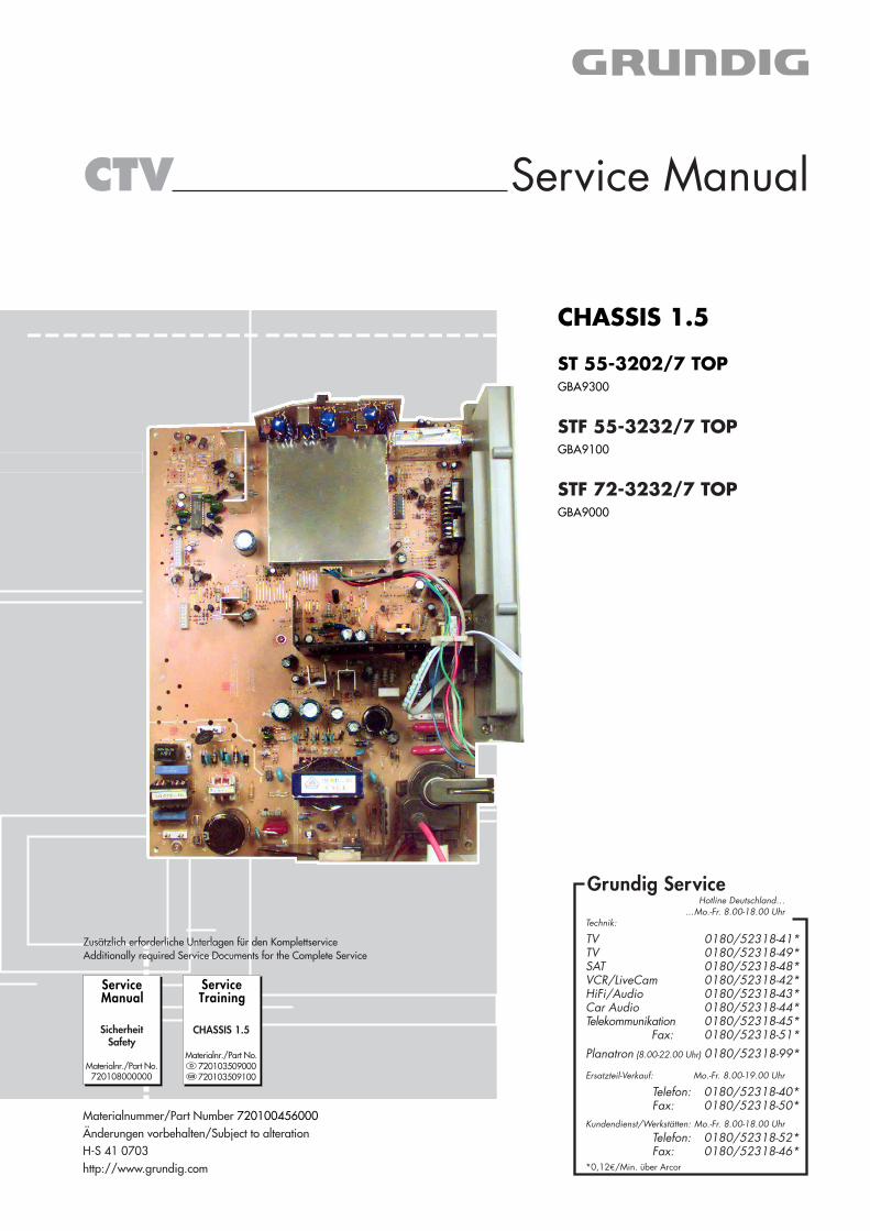
CHASSIS 1.5
ST 55-3202/7 TOPGBA9300
STF 55-3232/7 TOPGBA9100
STF 72-3232/7 TOPGBA9000
CHASSIS 1.5
Materialnr./Part No.� 720103509000� 720103509100
Grundig ServiceHotline Deutschland…
TVTVSATVCR/LiveCamHiFi/AudioCar Audio Telekommunikation
Fax:Planatron (8.00-22.00 Uhr)
0180/52318-41*0180/52318-49*0180/52318-48*0180/52318-42*0180/52318-43*0180/52318-44*0180/52318-45*0180/52318-51*0180/52318-99*
…Mo.-Fr. 8.00-18.00 Uhr
Telefon: 0180/52318-40*0180/52318-50*Fax:
Technik:
Ersatzteil-Verkauf: Mo.-Fr. 8.00-19.00 Uhr
Kundendienst/Werkstätten:
0180/52318-52*0180/52318-46*
Telefon:Fax:
*0,12€/Min. über Arcor
Mo.-Fr. 8.00-18.00 Uhr
GRUNDIG Service CHASSIS 1.5
1 - 2
Table of Contents
PageGeneral Section ........................................1-3-22General Notes .............................................................................. 1-3Service Notes ............................................................................... 1-3Technical Data ............................................................................. 1-4Operating Hints .......................................................................... 1-13Service and Special Functions ................................................... 1-21
Alignment.............................................. 2-3…2-4
Layout of the PCBsand Circuit Diagrams ......................... 3-1…3-12Oscillograms ................................................................................ 3-1ST 55-3202/7 TOP, STF 55-3232/7 TOP– Layout of PCBs
– CRT Tube ............................................................................. 3-2– NICAM .................................................................................. 3-2– Keyboard .............................................................................. 3-3– AV Socket Board .................................................................. 3-3– Chassis ................................................................................. 3-4
– Circuit Diagram– Chassis/CRT Tube/Keyboard/AV Socket Board/NICAM ...... 3-6
STF 72-3232/7 TOP– Layout of PCBs
– CRT Tube ............................................................................. 3-2– NICAM .................................................................................. 3-2– Keyboard .............................................................................. 3-3– AV Socket Board .................................................................. 3-3– IR Receiver ........................................................................... 3-3– Chassis ................................................................................. 3-8
– Circuit Diagrams– Chassis/CRT Tube/Keyboard/IR Receiver /
AV Socket Board ................................................................ 3-10– NICAM ................................................................................ 3-12
Spare Parts Lists .................................. 4-1…4-3
Inhaltsverzeichnis
SeiteAllgemeiner Teil ................................. 1-3…1-22Allgemeine Hinweise .................................................................... 1-3Servicehinweise ........................................................................... 1-3Technische Daten ........................................................................ 1-4Bedienhinweise ............................................................................ 1-5Service- und Sonderfunktionen .................................................. 1-21
Abgleich ................................................ 2-1…2-2
Platinenabbildungenund Schaltpläne ................................. 3-1…3-12Oszillogramme ............................................................................. 3-1ST 55-3202/7 TOP, STF 55-3232/7 TOP– Platinenabbildungen
– Bildrohrplatte ........................................................................ 3-2– NICAM .................................................................................. 3-2– Keyboard .............................................................................. 3-3– AV-Buchsenplatte ................................................................. 3-3– Chassis ................................................................................. 3-4
– Schaltplan– Chassis/Bildrohrplatte/Keyboard/AV-Buchsenplatte/NICAM 3-6
STF 72-3232/7 TOP– Platinenabbildungen
– Bildrohrplatte ........................................................................ 3-2– NICAM .................................................................................. 3-2– Keyboard .............................................................................. 3-3– AV-Buchsenplatte ................................................................. 3-3– IR-Empfänger ....................................................................... 3-3– Chassis ................................................................................. 3-8
– Schaltpläne– Chassis/Bildrohrplatte/Keyboard/IR-Empfänger/
AV-Buchsenplatte ............................................................... 3-10– NICAM ................................................................................ 3-12
Ersatzteillisten ...................................... 4-1…4-3
Es gelten die Vorschriften und Sicherheitshinweisegemäß dem Service Manual "Sicherheit", Material-nummer72010 800 0000, sowie zusätzlich die eventu-ell abweichenden, landesspezifischen Vorschriften!
The regulations and safety instructions shall bevalid as provided by the "Safety" Service Manual,part number 72010 800 0000, as well as therespective national deviations.

GRUNDIG Service CHASSIS 1.5
1 - 3
D
Service-HinweiseChassisausbauBevor Sie die Chassis-Verbindungsleitungen lösen, muss die Leitungs-verlegung zu den einzelnen Baugruppen wie Netzschalterplatte, Bedien-einheit, Bildrohrplatte, Ablenkeinheit oder Lautsprecher beachtet wer-den.Nach erfolgter Reparatur ist es notwendig, die Leitungsführung wiederin den werkseitigen Zustand zu versetzen, um eventuell spätereAusfälle oder Störungen zu vermeiden.
NetzkabelDiese Geräte dürfen nur mit dem Original-Netzanschlusskabel mitintegrierter Entstördrossel betrieben werden. Dieses Netzkabel ver-hindert Störungen aus dem Netz und ist Bestandteil der Geräte-zulassung. Im Ersatzfall bestellen Sie bitte ausschließlich das Netz-kabel laut Ersatzteilliste.
GB
Service NotesDisassembly of the chassisBefore disconnecting the chassis connecting leads observe the waythey are routed to the individual assemblies like the mains switchpanel, keyboard control panel, picture tube panel, deflection unit orloudspeaker.On completion of the repairs the leads must be laid out as originallyfitted at the factory to avoid later failures or disturbances.
Mains cableThe TV receiver must only be operated with an original mains connectingcable with an interference suppressor choke integrated in the mainsplug.This mains cable prevents interference from the mains supply andis part of the product approval. For replacement please order exclusivelythe mains connecting cable specified in the spare parts list.
F
Information pour la maintenanceDèmontage de chassisAvant de défaire les connecteurs du châssis princip, il y a lieu derepérer auparavant les liaisons correspondant à chaque platine commepar exemple le C.I. Inter secteur, le C.I. Commande, le C.I. Tube, lebloc déviation ou les haut-parleurs.A la fin de l'intervention, les connexions doivent être remises dans leurposition d'origine afin d'éviter par après d'éventuelles défaillances ouperturbations.
Cable dereseauCes appareils ne peuvent être utilisés qu ' avec un cable de connecionoriginal de réseau avec bobine antiparasite intégré dans la fiche desecteur. Ce câble de réseau empêche des perturbations de réseau etest partie de l'autorisation d'appareil. Si nécessaire commandezuniquement le cable de réseau selon la liste de pièces détachées.
I
Nota di servizioSmontaggio del telaioPrima di sfilare i cavi di collegamneto col telaio è necessario osservarela disposizione originaria degli stessi verso le singole parti come lapiastra alimentazione, l'unità comandi, la piastra cinescopio, il giogo ol'altoparlante.Dopo la riparazione è necessario che gli ancoraggi e le guidegarantiscano la disposizione dei cavi analogamente a quella data infabrica e ciò per evitare disturbi o danni nel tempo.
Cavo reteGli apperechi devono essere messi in funzioni solo con il cavo originaleil colle gamento di rete e la sua spina di rete deve essere munita di unabombina d´induttanza. In causa di sostituzione ordinate solo il cavo dialimentatore che corrésponde alla lista degli accessori.
E
Nota de servicioDesmontaje del chassisAntes de desconectar las conecciones del Chassis hay que observarla dirección de dichas conecciones a los distintos grupos de construccióncomo la placa de conmutación de red, unidad de control, placa delzócalo del tubo de imagen, unidad de deflección o altavoces.Después de haber realizado la reparación y para evitar fallos opertubaciones posteriores es necesario reponer las conecciones talcomo fueron instaladas originalmente en fabrica.
Cable de redEl aparato solo se puede usar con el cable de red original con choqueantiparásito integrado en el enchufe de red. Este cable de red evitaperturbaciones de la red y es parte de la autorización del aparato. Encaso necesario puede pedir el cable de red según lista de piezas derepuestos.
General Section
General NotesBefore opening the cabinet disconnect the mains plug!
WiringBefore disconnecting any leads and especially the earth connectingleads observe the way they are routed to the individual assemblies likethe chassis, mains switch panel, keyboard control panel, picture tubepanel, deflection unit, loudspeaker and so on.On completion of the repairs the leads must be laid out as originallyfitted at the factory to avoid later failures or disturbances.
Defective CRT or Cabinet (ST 55…, STF 55…)In the event of a defective picture tube or cabinet please contact yourlocal After-Sales Service.
Allgemeiner Teil
Allgemeine HinweiseVor dem Öffnen des Gehäuses zuerst den Netzstecker ziehen!
LeitungsverlegungBevor Sie die Leitungen und insbesondere die Masseleitungen lösen,muss die Leitungsverlegung zu den einzelnen Baugruppen wie z.B.Chassis, Netzschalterplatte, Bedieneinheit, Bildrohrplatte, Ablenk-einheit, Lautsprecher usw. beachtet werden.Nach erfolgter Reparatur ist es notwendig, die Leitungsführung wiederin den werkseitigen Zustand zu versetzen um evtl. spätere Ausfälleoder Störungen zu vermeiden.
Defekte Bildröhre/Gehäuse (ST 55…, STF 55…)Im Defektfall der Bildröhre/Gehäuse wenden Sie sich bitte an Ihreregionale Kundendienststelle.
GRUNDIG Service CHASSIS 1.5
1 - 4
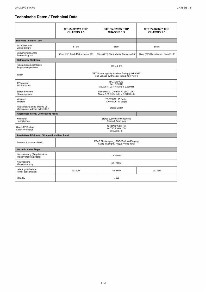
Technische Daten / Technical Data
ST 55-3202/7 TOPCHASSIS 1.5
STF 55-3232/7 TOPCHASSIS 1.5
STF 72-3232/7 TOPCHASSIS 1.5
Bildröhre / Picture Tube
Sichtbares Bild Visible picture 51cm 51cm 68cm
Bildschirmdiagonale Screen diagonal 55cm (21") Black Matrix, Novel 90° 55cm (21") Black Matrix, Samsung 90° 72cm (29") Black Matrix, Novel 110°
Elektronik / Electronic
Programmspeicherplätze Programme positions
Tuner
TV-Normen TV-Standards
Stereo Systeme Stereo systems
Videotext Teletext
Musikleistung ohne externe LS Music power without external LS
Anschlüsse Front / Connections Front
Kopfhörer Headphones
Cinch-AV-Buchse Cinch-AV socket
Anschlüsse Rückwand / Connections Rear Panel
Euro AV 1 (schwarz/black)
Netzteil / Mains Stage
Netzspannung (Regelbereich) Mains voltage (variable)
Netzfrequenz Mains frequency
Leistungsaufnahme Power consumption ca. 60W ca. 60W ca. 73W
Standby < 5W
1x FBAS Video / in 1x CVBS Video / in
2x Audio / in
FBAS Ein-/Ausgang, RGB-/S-Video EingangCVBS in-/output, RGB/S-Video input
110-240V
50 / 60Hz
Stereo 3,5mm Klinkenbuchse Stereo 3.5mm jack
199 + 2 AV
VST Spannungs Synthesizer Tuning (UHF/VHF)VST voltage synthesizer tuning (UHF/VHF)
B/G, I, D/K, K'PAL, SECAM
via AV: NTSC 4.43MHz + 3.58MHz
Deutsch A2 / German A2 (B/G, D/K) Nicam 5.85 (B/G, D/K) + 6.52MHz (I)
TOP/FLOF, 10 SeitenTOP/FLOF, 10 pages
Stereo 2x8W

GR
UN
DIG
Service
CH
AS
SIS
1.5
1 - 5
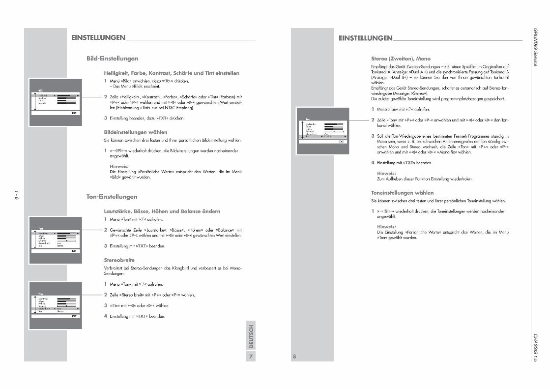
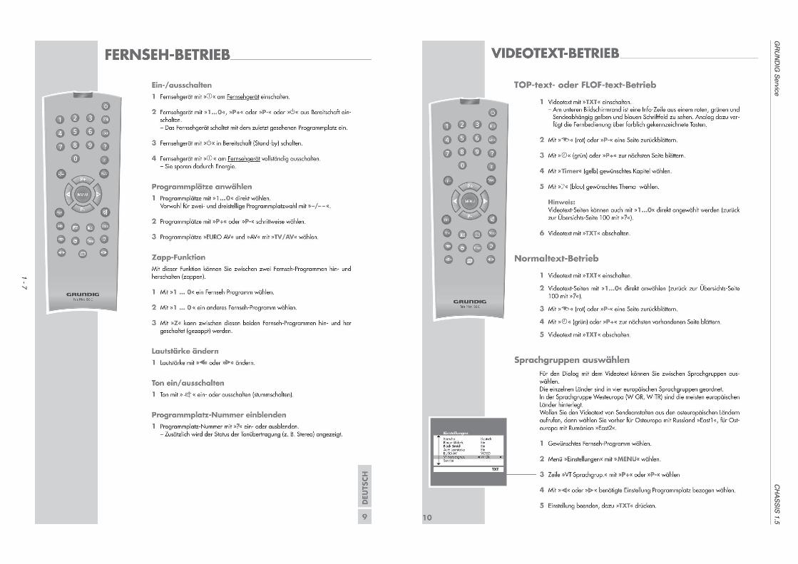
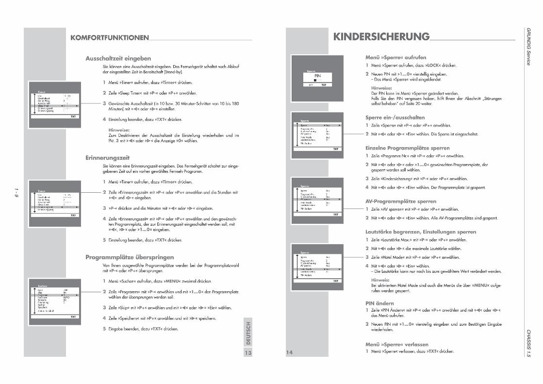
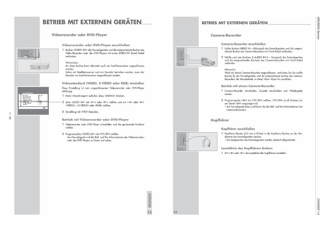
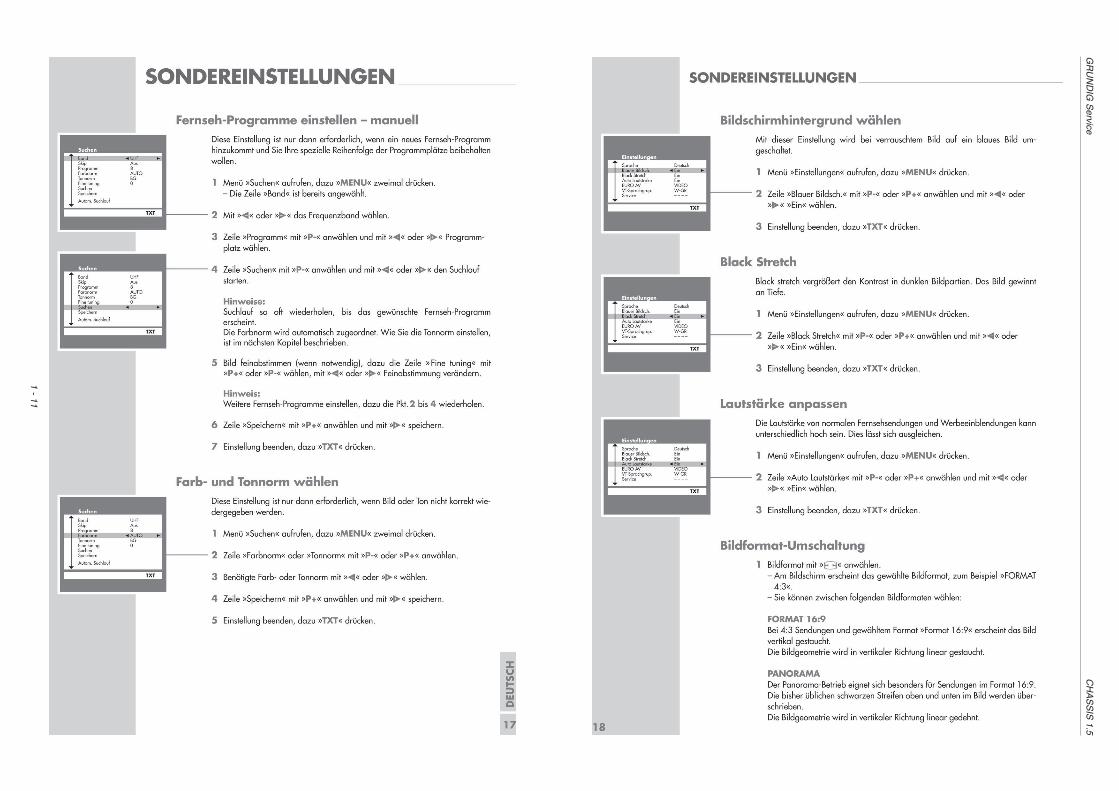
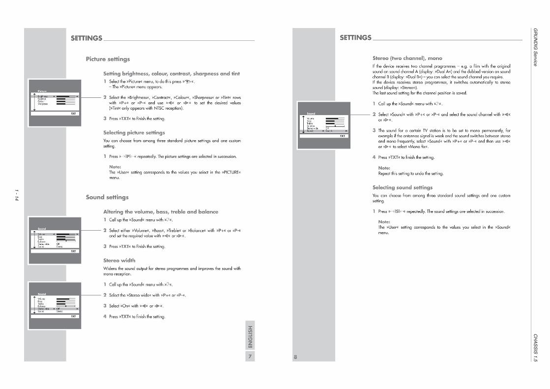
Bedienhinweise Dieses Kapitel enthält Auszüge aus der Bedienungsanleitung. Weiterge-hende Informationen entnehmen Sie bitte der gerätespezifischenBedienungsanleitung, deren Materialnummer Sie in der entsprechendenErsatzteilliste finden.
GR
UN
DIG
Service
CH
AS
SIS
1.5
1 - 6
GR
UN
DIG
Service
CH
AS
SIS
1.5
1 - 7

GR
UN
DIG
Service
CH
AS
SIS
1.5
1 - 8
GR
UN
DIG
Service
CH
AS
SIS
1.5
1 - 9
GR
UN
DIG
Service
CH
AS
SIS
1.5
1 - 10
GR
UN
DIG
Service
CH
AS
SIS
1.5
1 - 11

GR
UN
DIG
Service
CH
AS
SIS
1.5
1 - 12

GR
UN
DIG
Service
CH
AS
SIS
1.5
1 - 13
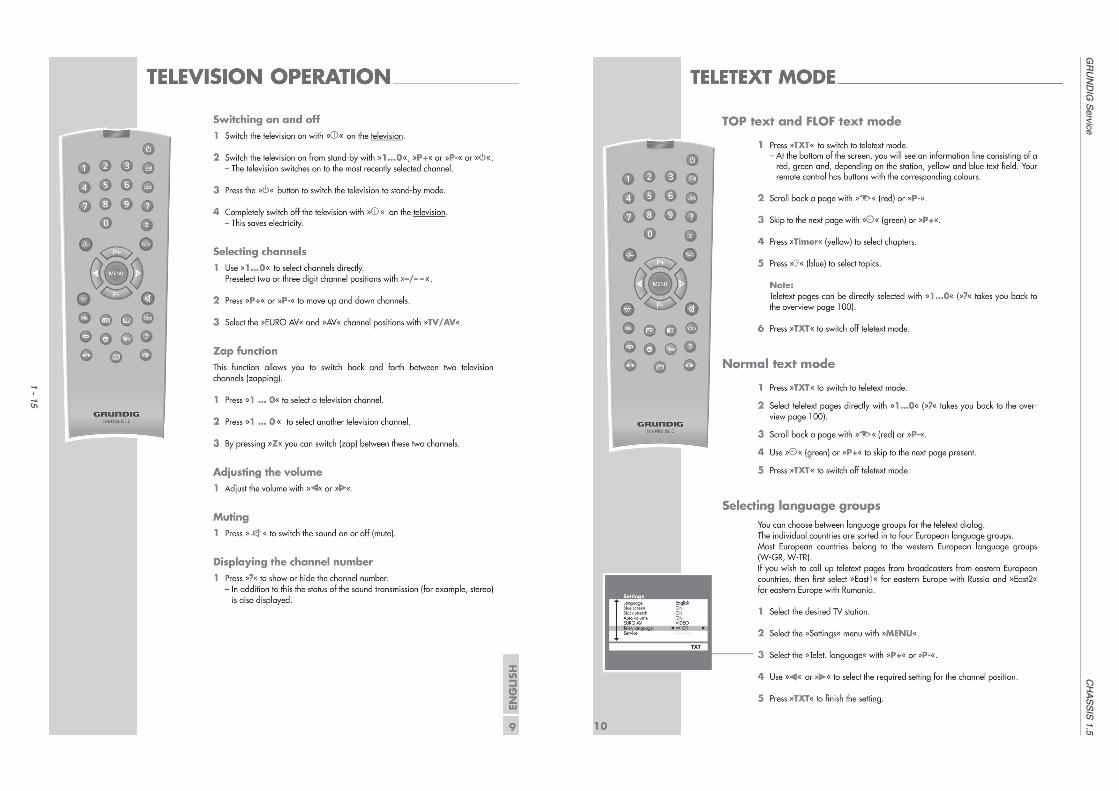
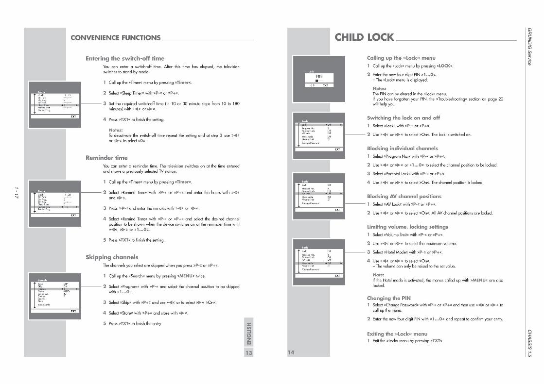
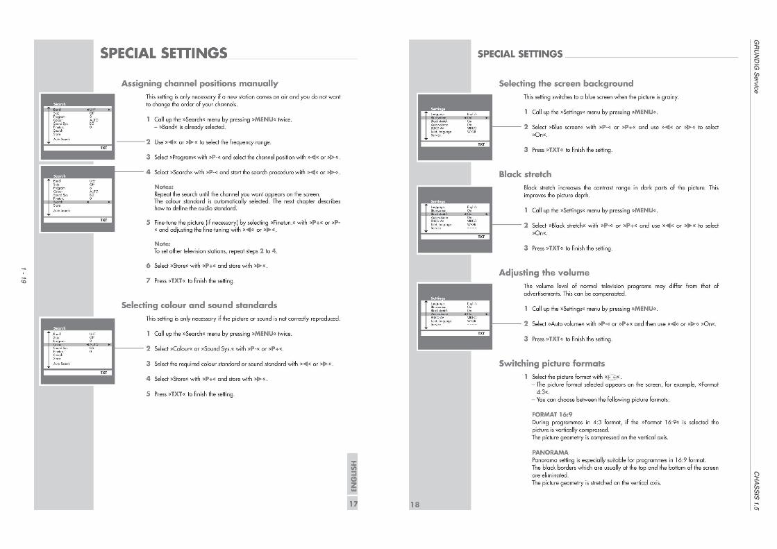
Operating Hints This chapter contains excerpts from the operating instructions. For furtherparticulars please refer to the appropriate user instructions the part numberof which is indicated in the relevant spare parts list.
GR
UN
DIG
Service
CH
AS
SIS
1.5
1 - 14
GR
UN
DIG
Service
CH
AS
SIS
1.5
1 - 15

GR
UN
DIG
Service
CH
AS
SIS
1.5
1 - 16
GR
UN
DIG
Service
CH
AS
SIS
1.5
1 - 17

GR
UN
DIG
Service
CH
AS
SIS
1.5
1 - 18
GR
UN
DIG
Service
CH
AS
SIS
1.5
1 - 19

GR
UN
DIG
Service
CH
AS
SIS
1.5
1 - 20

GRUNDIG Service CHASSIS 1.5
1 - 21
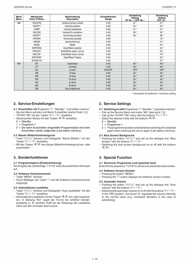
D Service- und Sonderfunktionen
1. Service-Menü1.1 TastenfunktionenDie Bedienung des Service-Menü erfolgt über die Fernbedienung.Aufruf des Service-Menü: Taste "MENU"Aufruf der Dialogzeile: Tasten "P+" oder "P-"Einstellung in der Dialogzeile ändern: Tasten � oder �Beenden des Service-Menü: Taste "TXT"Codezahl für Service-Menü: 8500
1.2 Aufruf des Service-Menü– Taste "MENU" drücken.– Dialogzeile "Service" mit den Tasten "P+" oder "P-" anwählen.– Codezahl "8500" eingeben.– Gewünschtes Menü (siehe Tabelle) mit den Tasten 0 (M0) bis 9 (M9)
anwählen.
MenüMenu
MenüpunktPoint of Menu
BeschreibungDescription
EinstellbereichRange
EinstellungSetting
ST 55… / STF 55…
EinstellungSetting
STF 72…M0 Auto Volume
FSLAuto volume level
Forced slicing levelON / OFFON / OFF
ONON
ONON
FMWS
FFI
Window selection of narrow-band sound PLL
Fast filter IF-PLLOSOFCO
Black switch offForced colour on
ON / OFF
ON / OFF
OFF
OFFON / OFFON / OFF
ONOFF
OFF
OFFONOFF
M1
DUAL OUTWOOFER
Dual Sound out optionNot relevant
BANDAV CFG
Band mode selectionAV mode selection
NTSC MXVIDEO OUT
NTSC Matrix selectionVideo out selection
PIN5RPO
PIN5 function selectionPeaking
0-1ON / OFF
1OFF
0-10-8
18
1OFF
18
USACVBS
0-3RGB
0
USACVBSRGB
0M2 VISION IF
DKBG
IM
SIF PREFER
AUTO SOUND
PRE TXT LANG
ON / OFF38,9M
ONON / OFFON / OFF
ONON
38,9MONONON
ON / OFF
BG, DK, I
OFF
BG
ON / OFFW-GR / W-TR
EAST1 / EAST2
ON
according shipment area
OFF
BG
ON
according shipment area
M3 START ONTXT CONT
AC power on start selectionTeletext contrast
TXT ROW24 MODERGB BRIGHT
Teletext Row 24 ModeRGB Brightness
M4
WHITE OSDSPANISH BIT
Background Color_White for displaySpanish Bit Control mode
SUBCONSUBCOL
Sub contrastSub color
0-220-63
035
0-10-15
00
03500
0-70-1
30
0-630-63
4550
306363
SUBSHPSUBTINT
Sub sharp
YDLY PALYDLY NTSC
Y-delay adj. for PALY-delay adj. for NTSC
YDLY SECYDLY AV
Y-delay adj. for SECAMY-delay adj. for AV
UOC VOL
CATHODE
The volume control of internal UOC ON/OFF
Cathode level
0-630-15
6315
0-150-15
1515
63151515
0-150-15
1515
ON / OFF
0-15
OFF
6
1515
OFF
7
M5
SC BRI
OSD VPOS
This setting will decide the Default value for the
SC item in Menu9Position of OSD vertical
OSD HPOS WIDE
Position of OSD horiz.Wide zoom adjustment
M6
M7
ZOOM
SHIPMODE
Zoom adjustment
Factory mode
AGC-TOPAGC-SPEED
Tuner AGCTuner AGC speed
0-63
0-63
31
40 *0-630-63
15 *15 *
31
40 *15 *15 *
0-63Grunddaten werden geladen und alle kundenspezifischen Daten gelöscht
Load basic data and delete all customer data
58 *
0-630-3
25 *1
58 *
25 *1
GB Service and Special Functions
1. Service Menu1.1 Functions of the buttonsFor navigating in the Service Menu, the buttons on the remote controlare used.Call up the Service Menu: Button "MENU"Call up the dialogue line: Buttons "P+" or "P-"Changing the setting in the dialogue line: Buttons � or �Exit the Service Menu: Button "TXT"Code number for Service Menu: 8500
1.2 Calling up the Service Menu– Press button "MENU".– Call up the dialogue line "Service" with the buttons "P+" / "P-" .– Enter the code number "8500".– Call up the desired menu (see table) with the buttons 0 (M0) to 9
(M9).
* individuelle Einstellwerte / individual setting
GRUNDIG Service CHASSIS 1.5
1 - 22
2. Service-Einstellungen2.1 Einschalten mit Programm "1", "Standby", "Last station memory"– Service Menü aufrufen und Menü 3 anwählen (siehe Punkt 1.2).– "START ON" mit den Tasten "P+" / "P-" anwählen– Gewünschten Modus mit den Tasten � / � einstellen.
0 = Standby1 = Programm 12 = Der beim Ausschalten eingestellte Programmplatz wird beim
Einschalten wieder aufgerufen (Last station memory).
2.2 Blauen Bildschirmhintergrund– Taste "MENU" drücken und Dialogzeile "Blauer Bildsch." mit den
Tasten "P+" / "P-" anwählen.– Mit den Tasten � / � den blauen Bildschirmhintergrund ein- oder
ausschalten
3. Sonderfunktionen3.1 Programmsperre (Kindersicherung)Die Eingabe der Zahlenfolge "7 0 3 8" hebt die persönliche Kennzahlauf.
3.2 Software-Versionsnummer– Taste "MENU" drücken.– Durch Betätigen der Taste "?" wird die Software-Versionsnummer
angezeigt.
3.3 Automatische Lautstärke– Taste "MENU" drücken und Dialogzeile "Auto Lautstärke" mit den
Tasten "P+" / "P-" anwählen.– Automatische Lautstärke mit den Tasten � / � ein- oder ausschal-
ten. In Stellung "Ein" regelt der Ton-IC bei erhöhter Sender-lautstärke (z. B. erhöhter HUB bei der Werbung) die Lautstärkeintern auf den normalen Wert zurück.
MenüMenu
MenüpunktPoint of Menu
BeschreibungDescription
EinstellbereichRange
EinstellungSetting
ST 55… / STF 55…
EinstellungSetting
STF 72…M8 VSLOPE
VSHIFTVertical picture center
Vertical positionVAMP
VSCORVertical amplitude
Vertical S-correctionHSHIFTHPARA
Horizontal positionHorizontal parable
HBOWWIDE
Horizontal bowWidth
0-630-63
37 *32 *
0-630-63
51 *30 *
37 *32 *51 *30 *
0-630-63
36 *–
0-630-63
––
36 *16 *31 *54 *
EWPARAEWUCP
East/West parableEast/West upper corner
EWLCPEWTRAP
East/West lower cornerEast/West Trapez
M9ZOOM VX
BT brightnessCTSC
contrastscreen
0-630-63
––
0-630-63
––
24 *22 *19 *33 *
0-630-63
–48 *
0-63ON/OFF
48 *OFF
31 *48 *48 *OFF
RBGB
R biasG bias
RDGD
R driveG drive
BDSB
B driveSub brightness
0-630-63
32 *32 *
0-630-63
32 *32 *
32 *32 *32 *32 *
0-630-63
32 *40 *
32 *40 *
2. Service Settings2.1 Switching on with Programme "1", "Standby", "Last station memory"– Call up the Service Menu and menu "M3" (see point 1.2).– Call up the "START ON" menu with the buttons "P+" / "P-".– Select the desired mode with the buttons � / �.
0 = Standby1 = Programme 12 = The programme position selected when switching off is selected
again when switching the set on again (Last station memory).
2.4 Blue Screen Background– Pressing the button "MENU" and call up the dialogue line "Blue
Screen" with the buttons "P+" / "P-".– Switching the blue screen background on or off with the buttons� / �.
3. Special Function3.1 Electronic Programme Lock (parental lock)Enter the key sequence "7 0 3 8" to cancel your personal code number.
3.2 Software Version Number– Pressing the button "MENU".– Pressing the "?" button displays the software version number.
3.3 Automatic Volume– Pressing the button "MENU" and call up the dialogue line "Auto
volume" with the buttons "P+" / "P-".– Switching the automatic volume on or off with the buttons "P+" / "P-".
In the "ON" position, the sound IC regulates the volume internallyto the normal value (e.g. increased deviation in the case ofadvertising).
* individuelle Einstellwerte / individual setting
GRUNDIG Service CHASSIS 1.5
2 - 1
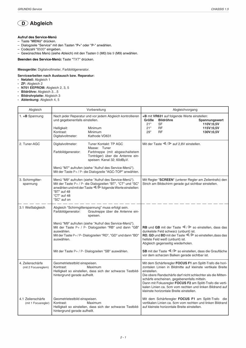
D Abgleich
Aufruf des Service-Menü– Taste "MENU" drücken.– Dialogzeile "Service" mit den Tasten "P+" oder "P-" anwählen.– Codezahl "8500" eingeben.– Gewünschtes Menü (siehe Ableich) mit den Tasten 0 (M0) bis 9 (M9) anwählen.
Beenden des Service-Menü: Taste "TXT" drücken.
Messgeräte: Digitalvoltmeter, Farbbildgenerator.
Servicearbeiten nach Austausch bzw. Reparatur:- Netzteil: Abgleich 1- ZF: Abgleich 2- N701 EEPROM: Abgleich 2, 3, 5- Bildröhre: Abgleich 3…5- Bildrohrplatte: Abgleich 3- Ablenkung: Abgleich 4, 5
1. +B Spannung
2. Tuner-AGC
3. Schirmgitter-spannung
3.1 Weißabgleich
4. Zeilenschärfe(mit 2 Focusreglern)
4.1 Zeilenschärfe(mit 1 Focusregler)
Nach jeder Reparatur und vor jedem Abgleich kontrollierenund gegebenenfalls einstellen.
Helligkeit: MinimumKontrast: MinimumDigitalvoltmeter: Kathode VD631
Digitalvoltmeter: Tuner Kontakt: TP AGCMasse: Tuner
Farbbildgenerator: Farbtreppe (mit abgeschaltetemTonträger) über die Antenne ein-speisen: Kanal 32; 60dBµV.
Menü "M7" aufrufen (siehe "Aufruf des Service-Menü").Mit der Taste P+ / P- die Dialogzeile "AGC-TOP" anwählen.
Menü "M9" aufrufen (siehe "Aufruf des Service-Menü").Mit der Taste P+ / P- die Dialogzeilen "BT", "CT" und "SC"anwählen und mit der Taste � / � folgende Werte einstellen:"BT" auf 48"CT" auf 48"SC" auf on
Abgleich "Schirmgitterspannung" muss erfolgt sein.Farbbildgenerator: Grautreppe über die Antenne ein-
speisen.
Menü "M9" aufrufen (siehe "Aufruf des Service-Menü").Mit der Taste P+ / P- Dialogzeilen "RB" und dann "GB"auswählen.Mit der Taste P+ / P- Dialogzeilen "RD", "GD" und dann "BD"auswählen.
Mit der Taste P+ / P- Dialogzeilen "SB" auswählen.
Geometrietestbild einspeisen.Kontrast: MaximumHelligkeit so einstellen, dass sich der schwarze Testbild-hintergrund gerade aufhellt.
Geometrietestbild einspeisen.Kontrast: MaximumHelligkeit so einstellen, dass sich der schwarze Testbild-hintergrund gerade aufhellt.
+B mit VR631 auf folgende Werte einstellen:Größe Bildröhre Spannungswert
21" SF 110V±0,5V21" RF 115V±0,5V29" RF 130V±0,5V
Mit der Taste � / � auf 2,8V einstellen.
Mit Regler "SCREEN" (unterer Regler am Zeilentrafo) denStrich am Bildschirm gerade gut sichtbar einstellen.
RB und GB mit der Taste � / � so einstellen, dass dasdunkelste Feld schwarz (unbunt) ist.RD, GD und BD mit der Taste � / � so einstellen,dass dashellste Feld weiß (unbunt) ist.Abgleich gegenseitig wiederholen.
SB mit der Taste � / � so einstellen, dass die Grauflächevor dem scharzen Balken gerade sichtbar ist.
Mit dem Schärferegler FOCUS F1 am Splitt-Trafo die hori-zontalen Linien in Bildmitte auf kleinste vertikale Breiteeinstellen.Die obere Randschärfe darf nicht schlechter als die Mitten-schärfe erscheinen, gegebenenfalls mitteln.Dann mit Fokusregler FOCUS F2 am Splitt-Trafo die verti-kalen Linien ca. 5cm vom rechten und linken Bildrand aufkleinste horizontale Breite einstellen.
Mit dem Schärferegler FOCUS F1 am Splitt-Trafo dievertikalen Linien ca. 5cm vom rechten und linken Bildrandauf kleinste horizontale Breite einstellen.
Abgleich Vorbereitung Abgleichvorgang
GRUNDIG Service CHASSIS 1.5
2 - 2
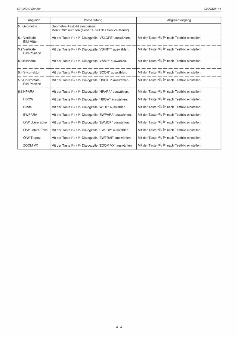
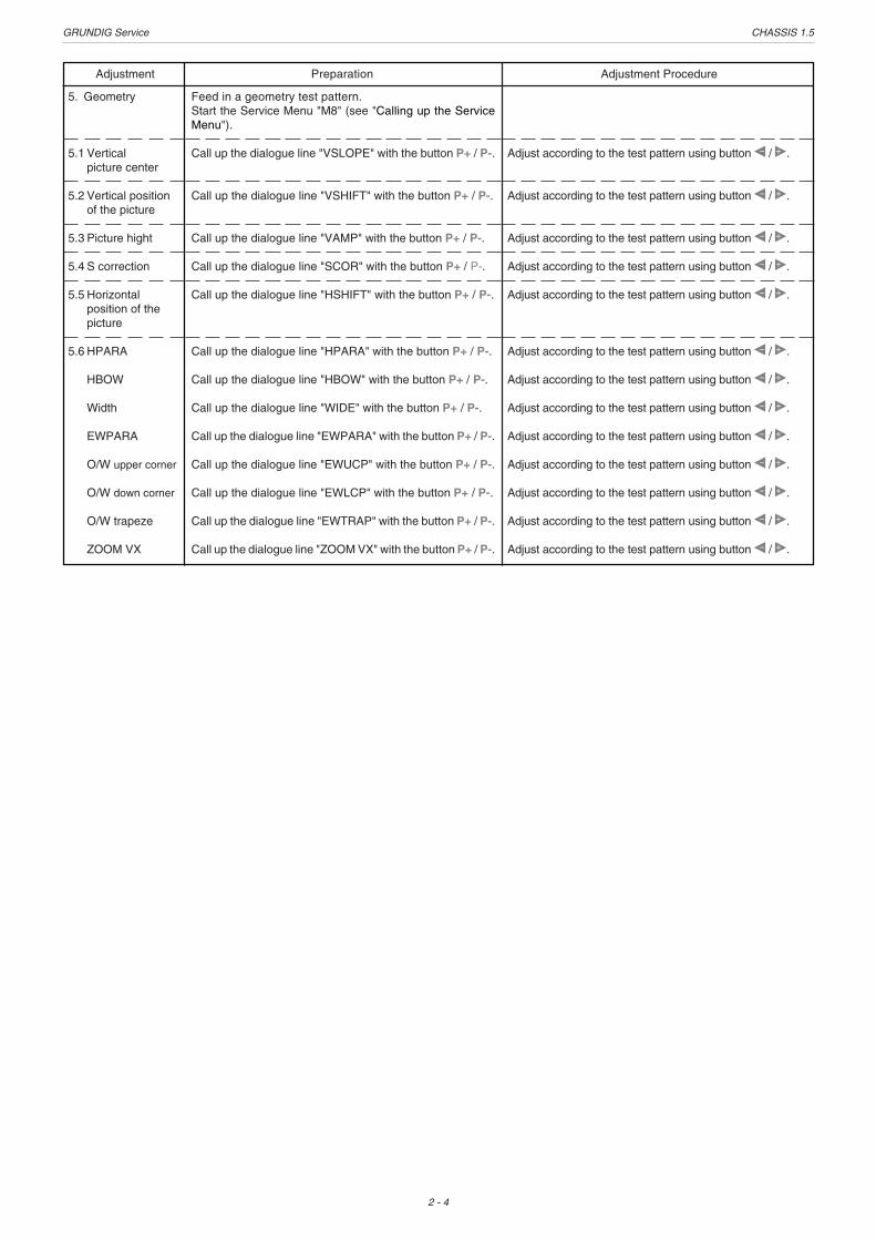
5. Geometrie
5.1 VertikaleBild-Mitte
5.2 VertikaleBild-Position
5.3 Bildhöhe
5.4 S-Korrektur
5.5 HorizontaleBild-Position
5.6 HPARA
HBOW
Breite
EWPARA
O/W obere Ecke
O/W untere Ecke
O/W Trapez
ZOOM VX
Geometrie-Testbild einspeisen.Menü "M8" aufrufen (siehe "Aufruf des Service-Menü").
Mit der Taste P+ / P- Dialogzeile "VSLOPE" auswählen.
Mit der Taste P+ / P- Dialogzeile "VSHIFT" auswählen.
Mit der Taste P+ / P- Dialogzeile "VAMP" auswählen.
Mit der Taste P+ / P- Dialogzeile "SCOR" auswählen.
Mit der Taste P+ / P- Dialogzeile "HSHIFT" auswählen.
Mit der Taste P+ / P- Dialogzeile "HPARA" auswählen.
Mit der Taste P+ / P- Dialogzeile "HBOW" auswählen.
Mit der Taste P+ / P- Dialogzeile "WIDE" auswählen.
Mit der Taste P+ / P- Dialogzeile "EWPARA" auswählen.
Mit der Taste P+ / P- Dialogzeile "EWUCP" auswählen.
Mit der Taste P+ / P- Dialogzeile "EWLCP" auswählen.
Mit der Taste P+ / P- Dialogzeile "EWTRAP" auswählen.
Mit der Taste P+ / P- Dialogzeile "ZOOM VX" auswählen.
Mit der Taste � / � nach Testbild einstellen.
Mit der Taste � / � nach Testbild einstellen.
Mit der Taste � / � nach Testbild einstellen.
Mit der Taste � / � nach Testbild einstellen.
Mit der Taste � / � nach Testbild einstellen.
Mit der Taste � / � nach Testbild einstellen.
Mit der Taste � / � nach Testbild einstellen.
Mit der Taste � / � nach Testbild einstellen.
Mit der Taste � / � nach Testbild einstellen.
Mit der Taste � / � nach Testbild einstellen.
Mit der Taste � / � nach Testbild einstellen.
Mit der Taste � / � nach Testbild einstellen.
Mit der Taste � / � nach Testbild einstellen.
Abgleich Vorbereitung Abgleichvorgang
GRUNDIG Service CHASSIS 1.5
2 - 3
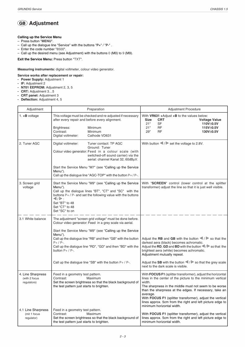
GB Adjustment
Calling up the Service Menu– Press button "MENU".– Call up the dialogue line "Service" with the buttons "P+" / "P-" .– Enter the code number "8500".– Call up the desired menu (see Adjustment) with the buttons 0 (M0) to 9 (M9).
Exit the Service Menu: Press button "TXT".
Measuring instruments: digital voltmeter, colour video generator.
Service works after replacement or repair:- Power Supply: Adjustment 1- IF: Adjustment 2- N701 EEPROM: Adjustment 2, 3, 5- CRT: Adjustment 3…5- CRT panel: Adjustment 3- Deflection: Adjustment 4, 5
1. +B voltage
2. Tuner AGC
3. Screen gridvoltage
3.1 White balance
4. Line Sharpness(with 2 focusregulators)
4.1 Line Sharpness(mit 1 focusregulator)
This voltage must be checked and re-adjusted if necessaryafter every repair and before every alignment.
Brightness: MinimumContrast: MinimumDigital voltmeter: Cathode VD631
Digital voltmeter: Tuner contact: TP AGCGround: Tuner
Colour video generator: Feed in a colour scale (withswitched-off sound carrier) via theaerial: channel Kanal 32; 60dBµV.
Start the Service Menu "M7" (see "Calling up the ServiceMenu").Call up the dialogue line "AGC-TOP" with the button P+ / P-.
Start the Service Menu "M9" (see "Calling up the ServiceMenu").Call up the dialogue lines "BT", "CT" and "SC" with thebuttons P+ / P- and set the following value with the buttons� / � :Set "BT" to 48Set "CT" to 48Set "SC" to on
The adjustment "screen grid voltage" must be done before.Colour video generator: Feed in a grey scale via aerial.
Start the Service Menu "M9" (see "Calling up the ServiceMenu").Call up the dialogue line "RB" and then "GB" with the buttonP+ / P-.Call up the dialogue line "RD", "GD" and then "BD" with thebutton P+ / P-.
Call up the dialogue line "SB" with the button P+ / P-.
Feed in a geometry test pattern.Contrast: MaximumSet the screen brightness so that the black background ofthe test pattern just starts to brighten.
Feed in a geometry test pattern.Contrast: MaximumSet the screen brightness so that the black background ofthe test pattern just starts to brighten.
With VR631 +Adjust +B to the values below:Size CRT Voltage Value21" SF 110V±0.5V21" RF 115V±0.5V29" RF 130V±0.5V
With button � / � set the voltage to 2.8V.
With "SCREEN" control (lower control at the splittertransformer) adjust the line so that it is just well visible.
Adjust the RB and GB with the button � / � so that thedarkest aera (black) becomes achromatic.Adjust the RD, GD and BD with the button � / � so that thebrightest aera (white) becomes achromatic.Adjustment mutually repeat.
Adjust the SB with the button � / � so that the grey scalenext to the dark scale is visible.
With FOCUS F1 (splitter transformer), adjust the horizontallines in the center of the picture to the minimum verticalwidth.The sharpness in the middle must not seem to be worsethan the sharpness at the edges. If necessary, take anaverage.With FOCUS F1 (splitter transformer), adjust the verticallines approx. 5cm from the right and left picture edge tominimum horizontal width.
With FOCUS F1 (splitter transformer), adjust the verticallines approx. 5cm from the right and left picture edge tominimum horizontal width.
Adjustment Preparation Adjustment Procedure
GRUNDIG Service CHASSIS 1.5
2 - 4
Feed in a geometry test pattern.Start the Service Menu "M8" (see "Calling up the ServiceMenu").
Call up the dialogue line "VSLOPE" with the button P+ / P-.
Call up the dialogue line "VSHIFT" with the button P+ / P-.
Call up the dialogue line "VAMP" with the button P+ / P-.
Call up the dialogue line "SCOR" with the button P+ / P-.
Call up the dialogue line "HSHIFT" with the button P+ / P-.
Call up the dialogue line "HPARA" with the button P+ / P-.
Call up the dialogue line "HBOW" with the button P+ / P-.
Call up the dialogue line "WIDE" with the button P+ / P-.
Call up the dialogue line "EWPARA" with the button P+ / P-.
Call up the dialogue line "EWUCP" with the button P+ / P-.
Call up the dialogue line "EWLCP" with the button P+ / P-.
Call up the dialogue line "EWTRAP" with the button P+ / P-.
Call up the dialogue line "ZOOM VX" with the button P+ / P-.
Adjust according to the test pattern using button � / �.
Adjust according to the test pattern using button � / �.
Adjust according to the test pattern using button � / �.
Adjust according to the test pattern using button � / �.
Adjust according to the test pattern using button � / �.
Adjust according to the test pattern using button � / �.
Adjust according to the test pattern using button � / �.
Adjust according to the test pattern using button � / �.
Adjust according to the test pattern using button � / �.
Adjust according to the test pattern using button � / �.
Adjust according to the test pattern using button � / �.
Adjust according to the test pattern using button � / �.
Adjust according to the test pattern using button � / �.
5. Geometry
5.1 Verticalpicture center
5.2 Vertical positionof the picture
5.3 Picture hight
5.4 S correction
5.5 Horizontalposition of thepicture
5.6 HPARA
HBOW
Width
EWPARA
O/W upper corner
O/W down corner
O/W trapeze
ZOOM VX
Adjustment Preparation Adjustment Procedure

GRUNDIG Service CHASSIS 1.5
3 - 1
Platinenabbildungen und Schaltpläne / Layout of the PCBs and Circuit Diagrams
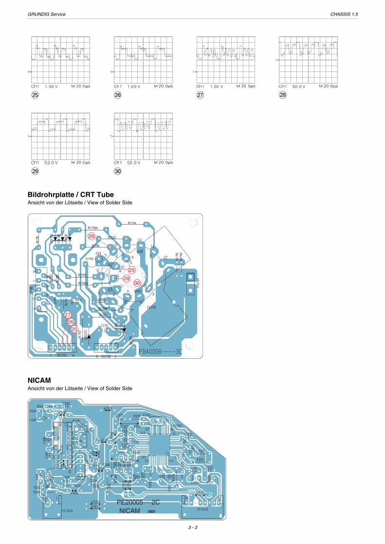
Oszillogramme / Oscillograms
1 2 3 4
5 6 7 8
9 0 ! @
# $ % ^
& * ( )
¡ ™ £ ≤
GRUNDIG Service CHASSIS 1.5
3 - 2
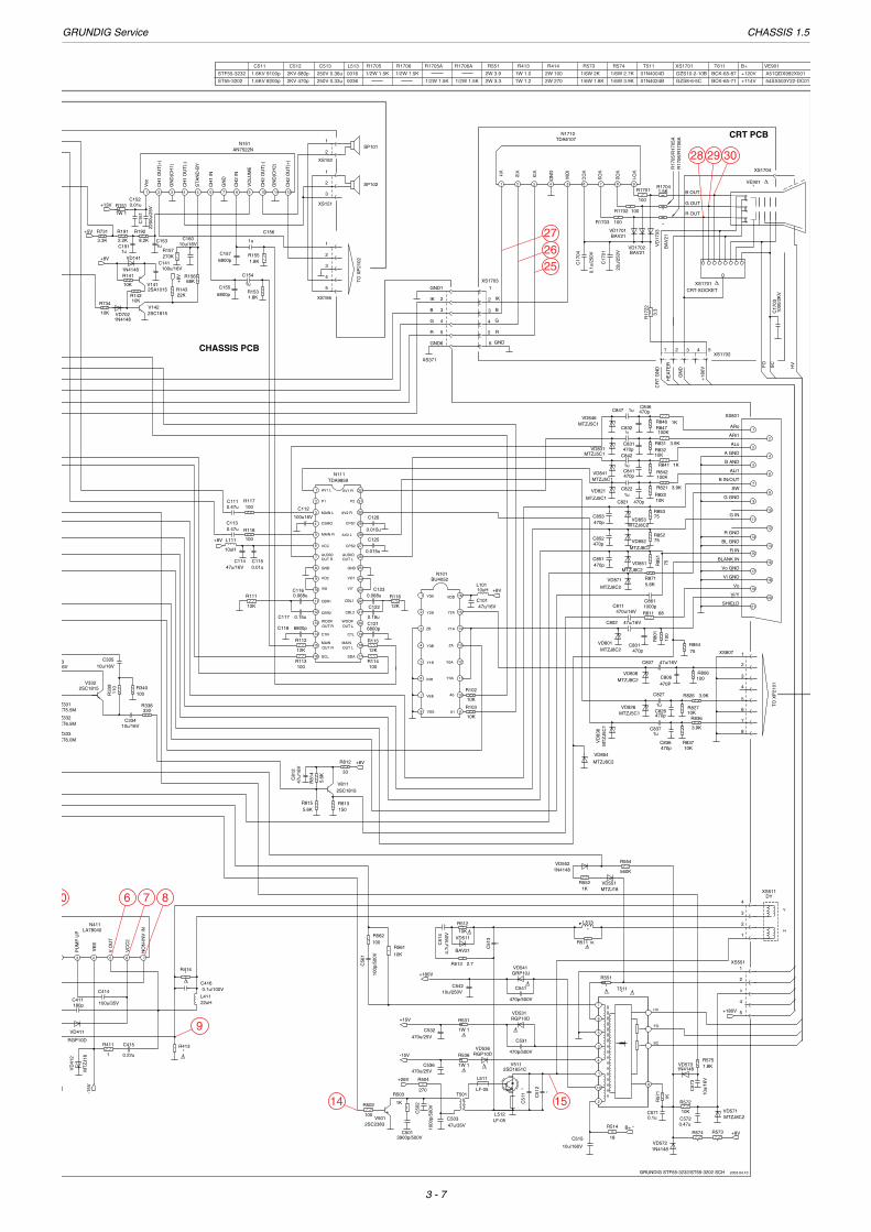
Bildrohrplatte / CRT TubeAnsicht von der Lötseite / View of Solder Side
2526
27
28
28
29
30
NICAMAnsicht von der Lötseite / View of Solder Side
PE20005----2CNICAM
∞ § ≥ •
ª º

GRUNDIG Service CHASSIS 1.5
3 - 3
Keyboard ST 55-3202/7 TOP, STF 55-3232/7 TOPAnsicht von der Lötseite / View of Solder Side
Keyboard STF 72-3232/7 TOPAnsicht von der Lötseite / View of Solder Side
PXC0013----1C
AV-Buchsenplatte / AV Socket Board ST 55-3202/7 TOP, STF 55-3232/7 TOPAnsicht von der Lötseite / View of Solder Side
AV-Buchsenplatte / AV Socket Board STF 72-3232/7 TOPAnsicht von der Lötseite / View of Solder Side
PXC0013----1C
PXC0013----1C
IR-Empfänger / ReceiverSTF 72-3232/7 TOPAnsicht von der Lötseite / View of Solder Side
GRUNDIG Service CHASSIS 1.5
3 - 4
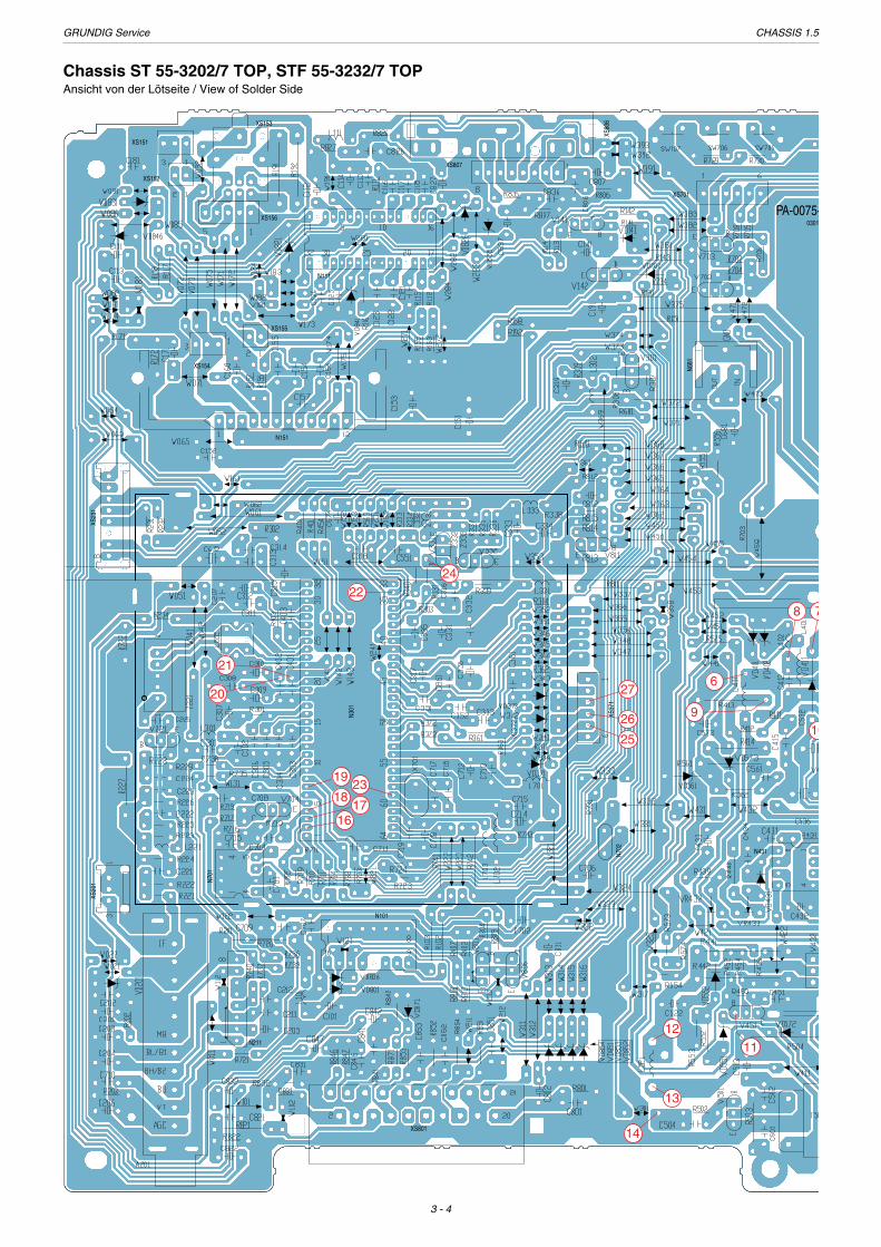
Chassis ST 55-3202/7 TOP, STF 55-3232/7 TOPAnsicht von der Lötseite / View of Solder Side
N301
N211
N701
XS37
1
N431
XS155
N702
N101
XS154
N151
N111
XS807
XS80
6XS153
XS801
XS20
1XS
231
N681
XS701
PA-0075-0301
XS156
XS152
XS151
6
78
910
13
14
1211
16
18
19
21
20
22
17
23
24
25
26
27

GRUNDIG Service CHASSIS 1.5
3 - 5
N41
1
XS551
N656
N671
XS51
1
T511
N612
75----1C030102
T611
N61
1
XS602
HOTCOLD
T3.15A AC250V
XS601
N703
SW601
1
52
4
3
7
10
15
GRUNDIG Service CHASSIS 1.5
3 - 6
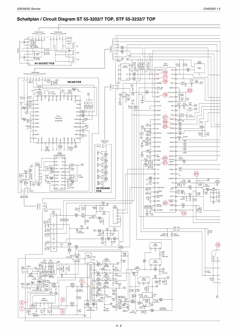
Schaltplan / Circuit Diagram ST 55-3202/7 TOP, STF 55-3232/7 TOP
t
2
VC
C
1
INV
IN
35 34
33SLKVD
D4
3940 38 37
P1
36
VS
S4
44 43 4142
VSS3
VD
D3
P2
1 L OUT
32WS
30SDA
31SDO
2 R OUT
4 VSSA1
3 VDDA1
28
29SCL
VDDD3TDA9874AH
N3102
26
27VSSD3
CRESET
NICAM DEM6
5 VSSD1
VDDD1
8
7 VSSD2
VDDD2
VR
EF
2
EX
T L
EX
T R
FM
IN
SY
SC
LK
25SIF1
23SIF2
24VREF1
9 TP2
11 TP1
10 NICAM
2221191816 17 2015141312
TE
ST
1
VD
DA
2
VD
DA
2
PC
LK
AD
DR
1
XT
ALI
XT
ALO
TE
ST
2
IRE
F
AD
DR
2
IF DEMODURATOR
20
19SIF
1
VIF2
SIFVIF
18VP3 TADJ
16GND
17CVAGC
5
4 TPLL
CSAGC
15VC026 VOAF
14VC01CAF7
138 CVP/2 AFC
12T AGC9 V OUT
11FM INQSS10
+
TP GND
TP AFC
+
+
+
FROM XP2102
5 4 3 2 14
6
5
8
2
3
9
1
7
FROM XS231
12345XP2101
6XS2101
TO
XS
3102
FROM XS231
8765432
+
1XS3102
FROM XS201
123XS3101
+ +
5
3
4
2
1
+
+
+
+
TO
XP
2001
TO
XS
3101
21
FROM XS701
XP2001
XS201
3
2
1
XS701
2
1
5
6
7
8
3
4
XS231
1
2
+
321
++
+
+
+
TPAGC
+
H:ON L:OFFSTANDBY
A
RK
B+ ADJ
TP91XP601 XS601
XS602
1
2
2
1
++
+
+
+
+
++
5
3
4
2
1
++
+
+
7
8
SCL 6
SDA 5
2
1
3
4
64IRIN1 STAND BY
63AV2
61
62AV1
VddP
2 SCL
4
3 SDA
TUNING
60RESET
58
59XTAL OUT
XTAL IN
5 NTSC SW/AC TEST
7
6 KEY
VOL1
57OSCGND
56VddC
8 MUTE
9 Vss C/P
54VddA
53BOUT
11 BAND2
12 Vss A
51ROUT
50BLANKING
14 Vp2
15 DECDIG
13 52SECPLL GOUT
48B2/UIN
47G2/YIN
17 PHL1LF
18 GND3
45
46
INSSW2
R2/VIN
44/AMOUT
AUDOUT
20
19 DECBG
AVL
21 VDRB
/EWD
16 49PHL2LF BCLIN
10 55BAND1 VpE
42
43
CVBS/Y
CHROMA
41GND1
23
22 VDRA
IF1
24 IF2
39
40CVBSINT
38IFVO /SVO
Vp126
25 IREF
VSC
27 TUNER AGC
37PLL IF
35/QSSOAUDEXT
36EHTO
28AUDEEM/SIF1
DECSDEM
30
/SIF2
GND2
29
34FBISO
33H OUT
31SNDPLL/SIF AGC
32 AVL/REFO
+
+
+
321
+
321
+
++
+
161
15
10
14
3
127
13
118
4 3
21
+
+
IF
MB
BH
BL
BU
TU
AGC
GND
GND
P10X180MRS601
N3101TDA9808
10u/16VC551
10uHL333
1.5KR633A
10u/16VC574
10u/16VC1203
10u/16VC1204
100
R12
01
100R1202
5.6KR715
120pC704
0.015uC1202
0.015uC1201
XS
2102
AL2i
AR2i
V2i
10uH
L3100
47u/16VC3100
+5V-1
+5V-1
+5V-1
+5V-1
+5V-1
0.01C3117
0.01C3116
2.2uC3114
2.2uC3115
K9260MFL3101
+5V
-1
3.3
R3129
0.47C3131
0.47C3130
47u/16V
C3134
100
R31
31
+5V
-1
10R3130
0.47
C3135
V31
01
2SC
1674
C
1KR3103
1000C3102
100
R3127
100
R3125
47
C3126
1uC3128
0.47C3129
8.2K
R31
22
0.47C3125
+5V-1
0.1C3127
10
R3116
0.47C3119
0.47C3118
0.47
C3120
10
R3117
0.01
C3108
0.22C3109
22KR3108
22K
R3107
77.8MHZ
L3101
24.576MX3201
10R
3124
10K
R31
26
10K
R31
28
1000
C31
01
0.01
C31
36
0.22
C3103
180
R3104
0.1
C3104
2.2uC3106
470
R31052.2uC3105
22K
R31
02
22KR3101
+3.
3V
100
R232
100R231
+5V-1
0.1u
C710
2 12
R68
0
+5V-1
1000u/16VC681
N681KA7805
LF-011L602
TV
R4J
VD
606
1000/1KVC606
1000/1KV
C605
TV
R4J
VD
605
1000/1KV
C603
TV
R4J
VD
603
1000/1KV
C60
4
TV
R4J
VD
604
3.3uC206
4.7uC204
4.7uC203
10u/
16V
C20
1
3.9KR722
MTZJ8C2VD402
MTZJ8C2VD401
1uHL401
1uHL402
4.7uC310
0.01uC703
47u/16VC702
1/2W 0.47R666
33R6611/2W 0.47
R651
1/2W 0.47
R646
1/2W 0.47R641
5V1HSCVD616
L611
LF-05
MT
ZJ8
C2
VD
561
27K
R563
0.1u
C316
47u/16VC333
XT6.0Z333
XT6.5Z332
XT5.5Z331
8.2uH
L332
2SC1815V331
+8V
10uHL331
100u/16VC331
0.01
u
C33
2
2.2KR501
27KR556390
R303
100KR555
220R333
100
R3341.8K
R331
0.1u
C336
1KR304
10u/16VC317
0.022u
C3510.022u
C3520.022u
C353
560pC361
33K
R36
2
22KR363
+8V
10K
R361
330
R371330
R372
330R373
+3.3V
10uH
L701
10u/16VC712
0.01u
C713
33pC717
33pC716
12MX701
+3.3V10u/16VC714
0.01uC715
10uHL702
+3.3V2.2u
C718
0.01u
C719 10uHL703
N7030038A2
3.3KR741
3.3KR742
100
R743
+15
V
R
0.033uC412
1.5KR404
1.5KR412
2.7KR302
4.7uC315
10u/
16V
C31
247
00p
C31
4
820p
C31
3
3300pC311
0.022uC207
0.1u
C40339K
R403
D2901CZ221
100
R402
100
R401
1000
p
C40
2
1000
p
C40
1
2.2uC309
0.1uC308
15KR301+
8V
10uH
L301
1uC307
47u/16VC302
0.01uC303
4700pC306
2200pC305
0.22uC304
0.22uC301
MTZJ5C1VD201
+8V1
22R201
680
R204
150K
R20
3
33K
R20
2
0.01
uC
202 10
K
R74
0
10K
R73
7
+8V
2SC1674CV221
1uHL221
0.01uC223
0.01uC225
1000p
C221
82R229
10
R228
10R227
220R226
4.7KR223
1.2KR224
68
R221
+8V
3.3K
R73
9
3.3K
R73
6
SW
2007
ME
NU
SW
2006
TV
/AV
SW
2004
V-
SW
2003
V+
SW
2002
P-
SW
2001
P+
1.2K
R20
25
2K
R20
26
2.7K
R20
27
5.1K
R20
28
6.8K
R20
29
10KR724 47
R723
B+ *
KA33VN702
10uC706
0.01uC707
0.1uC709 0.1u
C708
2
8.2K
R718
10K
R721
10K
R720
10KR717
10K
R719
PH2369V704
2.2KR716
120pC705
+5V
+3.3V
AT24C16N701
100
R711
100
R709
3.3K
R71
2
3.3K
R71
0
3.3K
R70
1
3.3K
R73
3
N301TDA9361
330
R70
8
330R705
VD701
1KR704
1KR707
22K
R703
22KR706
2SC1815V703
2SC1815V702
100u
/16V
C66
1
+3.3V
HZ3C2VD661
100u/35V
C642
+26V
470u/16VC671
10K
R702
+8V2
22
R671
N671KA7808
2SB1443V666
1N41
48V
D66
7
1.2KR668
10KR667
+5V
470u
/16V
C65
6
N656KA7805
0.01uC701
2SC1815V701
12KR653
TL431LPV631
1N4148
VD652
1N4148
VD632
0.033u
C633
1KR635
10K
R636
2.4KR634
20KVR631
51KR63351K
R632
220u/160VC632
220R652
1000u/16VC667
2200u/25VC652
2200u/25VC647
B+ *
+13V
470p/1KVC641
470p/2KVC631
470p/1KVC666
470p/1KVC651
470p/1KVC646
RGP10DVD641
RGP10JVD631
RGP15DVD666
RGP10DVD651
RGP15DVD646
LM-01L911
*T611
12M
R620
12M
R619
3.3KR616
2.2R615
1N4148VD615
RGP10JVD614
RGP10JVD613
PC817B/CN612
220u
/400
V
C61
0
68KR612
68KR611
TVR4JVD611
1000p/AC400VC620
470pC614
0.033uC619
0.1uC618
1000
p/2K
VC
611
470p/AC 400VC608
51.8
R602
LF-013L601
220K
R601
0.22
u/A
C27
5V
C601
F601T3.15AL/AC 250V
A04SW601
2.4KR617
33uC617
680p/2KV
C616
1000
/1K
VC
615
KA5Q0765N611
A201032
KEYBOARDPCB
NICAM PCB
AV SOCKET PCB
!
!
!
!
!
!
!
!
!
!
!!
!
!
!
! !
!
!
!
!
!
!
43 51 2
1
23
5
4
10
14
1617
2021
272625
22
23
24
18
19
GRUNDIG Service CHASSIS 1.5
3 - 7
+114V
+120V
B+
2W 3.9
1/6W 1.8K
1/6W 2K
R573
1/2W 1.5K 1/2W 1.5K 2W 3.3
1/2W 1.5K
54SX503Y22-DC01
A51QDX992X001
VE901
BCK-65-71
BCK-65-87
T611R551R1706AR1705A
GZS8-6-5C1/6W 3.9K 01N4024B2W 270
XS1701T511R574R414
GZS10-2-10B1/6W 2.7K 01N4004D2W 100
1W 1.2
R413
1W 1.0
R1705
1/2W 1.5K
R1706
0036
0016
L513
250V 0.33u
250V 0.36u
2KV 470p
2KV 680p
C513C512C511
1.6KV 8200p
1.6KV 9100p
ST55-3202
STF55-3232
8 9
VO
2
VO
1
5 6 7
IOM
VC
C
VO
3
42 3
VI2
VI3
GN
D
1
VI1
12
VO
LUM
E
CH
2 IN
GN
D
CH
1 IN
8 1095 6 7 11
CH
2 O
UT
(+)
GN
D(C
H2)
CH
2 O
UT
(-)
ST
AN
D-B
Y
Vcc
2 3 41
CH
1 O
UT
(-)
GN
D(C
H1)
CH
1 O
UT
(+)
3
2
1ARo
ARi1
ALo
A GND
6
5
9
7
8
B AND
ALi1
SW
G GND
B IN/OUT
4
11
10
13
14
12
G IN
R GND
BL GND
15
17
16
18
19
20
BLANK IN
Vo GND
Vo
Vi/Y
Vi GND
R IN
21SHIELD
76543
VE
E
NO
N-I
NV
IN
VC
C2
V O
UT
PU
MP
UP
SP102
SP101
+
2
1
TO
XP
2102
XS156
5
4
3
XS807
TO
XP
2101
8
7
6
5
4
3
2
1
+
XS152
1
XS151
3
2
2
1
XS551
5
4
3
2
1
1
2
4
3
GND
R
G
GND
IK
B
XS371
6
5
4
3
2
1
+
+
+
+
+
+
V
H
+
+
HV7
FO
SC
8
5
4
3
1
10
2
6
+
+
+
+
+
+
+
+
+
+
32AV1 L1 AV1 R
30
28
29
26
27
GND
VO1 24
25
VI7
22
23
20
21
CTL 19
SDA 17
18
MAIN L
MAIN R
CSMO4
5
3
VCC
OUT RAUDIO
GND
VO2
8
9
6
7
VI8
CBR1
CBR2
WOOF
12
13
10
11
MAIN
CTR
SCL
OUT R15
16
14
OUT R
AV2 L
AV2 R
CPS1
CPS2
CBL1
CBL2
OUT LMAIN
OUT LWOOF
OUT LAUDIO
312 P1 P2
+VDD
Y2A
16
15
Y1A
ZA 13
12
14
10
9
A0
A1
Y3A 11
1
2 Y2B
Y0B
4
5
3 ZB
Y1B
Y3B
7
8
6 INH
VSS
VEE
Y0A
+
+
+
+
+
+
+
+
+
+
+
+
N1710TDA6107
AN7522NN151
XS801
LA78040N411
1W 1
R151
*
R551
10uHL101
3.3
R17
22
1uC1538.2K
R192
2.2K
R191+5V
1
R411
2003.04.10GRUNDIG STF55-3232/ST55-3202 SCH
270KR157
10u/16VC160
68KR156
470pC851
470pC852
470pC853
5.6KR871
100
R118
100R117
MTZJ8C2
VD854
MT
ZJ5
C1
VD
836
MTZJ5C1VD826
MTZJ5C1VD841
MTZJ5C1
VD821
MTZJ5C1VD831
MTZJ5C1VD846
MTZJ8C2VD806
MTZJ8C2VD801
5.6KR815
1N4148VD702
*VE901
1.5KR1704
*
R17
06/R
1706
A
*
R17
05/R
1705
AB
AV
21
VD
1703
100
R1701
100R1703
BAV21VD1701
100R1702
0.1u
/250
V
C17
04
22u/
250V
C17
01 BAV21VD1702
CRT-SOCKETXS1701
G OUT
R OUT
B OUT
1000
/2K
VC
1703
1W 1
R531
1
10K
R561
100p
/500
V
C56
1
100R562
100
R502
10u/250VC542
+180V
4.7u
/160
VC
514
BAV21
VD511
1
10K
R512
2.7R513
*
C51
3
+180V
470u/25VC532
+15V
-15V
+26V
2SC2383V501
1K
R503
RGP10DVD536
2
270
R504
1W 1
R536
3900p/500VC501
1000
p/50
0V
C50
2
470u/25VC536
47u/35VC503
T501
*
L513
1
1KR511
470p/500V
C541
GRP10JVD541
RGP10DVD531
470p/500V
C531
*C
511 *
C51
2
L511
LF-05
L512LF-05
DYXS511
V5112SD1651C
MTZJ18VD551
1N4148VD552
1KR552
560K
R554
10u/160V
C515
10
18
R514 B+ *+8V
MTZJ8C2VD571
1N4148VD572
1N4148VD573
10u/
16V
C57
3
0.47uC5720.1u
C571
1.8KR575
*
R573
*
R574
10K
R572
1KR57
1
*T511
+8V
22KR143
10K
R734
2SA1015V141
10KR142
+8V
100u/16VC141
10K
R1411N4148
VD141
2SC1815V142
1.8KR155
6800pC157
1u
C156
6800p
C1551u
C154
1.8KR153
1uC191
+13V
2200
u/25
V
C15
1
0.01uC152
+8V
150R813
47u/
16V
C81
2
5.6K
R81
4 33
R812
2SC1815V811
75R854
1000pC861
0.015u
C126
0.015u
C125
0.15u
C122
0.068uC123
12K
R116
6800pC121
100R114
12K
R115
100R113
12K
R112
6800pC118
12K
R111
0.15uC117
0.068uC116
+8V
10uH
L111
47u/16VC114
0.01uC115
0.47uC113
0.47uC111
100u16V
C112
TDA9859N111
10K
R103
10K
R102
+8V
47u/16VC101
N101BU4052
1uC837
470pC836
10KR837
3.9K
R83610KR827
470pC8261u
C827 3.9KR826
470PC806
47u/16VC807
100R806
47u/16VC802
100
R80
1470p
C801
68R811470u/16VC811
MTZJ8C2VD851
MTZJ8C2
VD871
MTZJ8C2VD852
MTZJ8C2VD853
75R85
1
75R852
75R853
1KR841
100KR842
1u
C842
470pC841
3.9KR831
10KR832
1uC832
470pC831
1KR846
100KR847
1uC847 470pC846
1uC822
470pC821 10KR822
3.9KR821
10u/16VC334
330R338
100R340
110
R33
9
10u/16VC335
6V3
XT6.0MZ333
XT6.5MZ332
XT5.5MZ331
2SC1815V332
22uHL411
0.1u/100VC416
2*
R414
1
*R413
0.22u
C415
MT
ZJ1
8
VD
412
-15V
100u/35V
C414
180pC411
RGP10D
VD411
3.3K
R731
XS1704
CHASSIS PCB
CRT PCB
1
IK
3 B
2
XS1703
HV
SC
FO
4 5
+18
0V
32XS1702
1
GN
D
CR
T G
ND
HE
AT
ER
5 R
6 GND
G4
!
!
!
!
!
!
!
!
!
!
!
!
!
60 7 8
9
14 15
272625
28 29 30
GRUNDIG Service CHASSIS 1.5
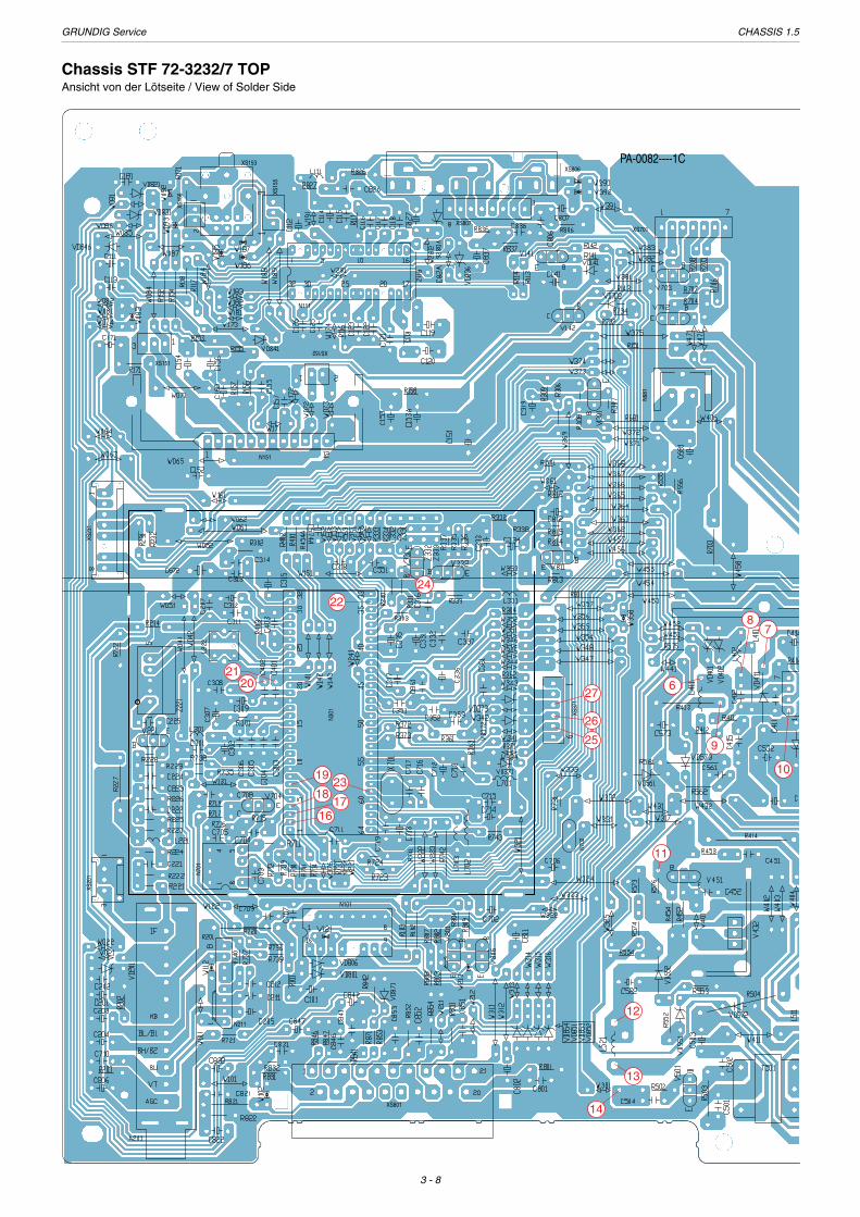
3 - 8
Chassis STF 72-3232/7 TOPAnsicht von der Lötseite / View of Solder Side
N301
N211
N701
XS37
1
XS152
N702
N101
XS151
N151
N111
XS807
XS806XS153
XS801
XS20
1XS
231
N681
PA-0082----1C
XS15
5
XS15
6
XS701
6
78
9
10
13
14
12
11
16
18
19
2120
22
17
23
24
25
26
27
GRUNDIG Service CHASSIS 1.5
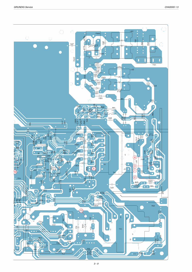
3 - 9
XS551
N656
N671
XS51
1
N612
15
2
4
3
10
15

GRUNDIG Service CHASSIS 1.5
3 - 10
Schaltplan / Circuit Diagram STF 72-3232/7 TOP
+
+
+
+
+
+
+
+
+
+
VE
E
PU
MP
UP
VC
C
INV
IN
1 2 3 4
+
+
321
+
B+ ADJ
321
+
321
STANDBYL:ON H:OFF
KR
A
64
62
61
60
59
63
IRIN1 STAND BY
AV1
VddP
RESET
XTAL OUT
3
4
5
6 KEY
TUNING
/AC TEST
SDA
NTSC SW
SCL2 AV2
57
56
55
54
52
51
50
49
53
OSCGND
VddC
VpE
VddA
8
9
10
11 BAND2
Vss C/P
BAND1
MUTE
GOUT
ROUT
BLANKING
BCLIN
13
14
15
16 PHL2LF
DECDIG
Vp2
SECPLL
Vss A12 BOUT
XTAL INVOL17 58
48
46
47
45
44
43
41
42
40
39
B2/UIN
R2/VIN
G2/YIN
INSSW2
/AMOUT
AUDOUT
17
19
18
20
21 VDRB
AVL/EWD
DECBG
PHL1LF
GND3
CHROMA
GND1
CVBS/Y
CVBSINT
Vp1
22
24
23
25
26 VSC
IREF
IF2
VDRA
IF1
38
36
37
35
34
33
IFVO /SVO
EHTO
PLL IF
AUDEXT/QSSO
FBISO
27
29
28
30
31SNDPLL/SIF AGC
/SIF1
DECSDEM
GND2
/SIF2
AUDEEM
TUNER AGC
H OUT 32 AVL/REFO
+
1
3
4
2
1
4
3
2
IR RECEIVER PCB
5
XS701XS2201
5
+
XS701
1
2
KEYBOARD PCB
2
XS2001
1
++
+
1
3
2
7
8
SCL 6
SDA 5
2
1
3
4
XS201
+
TPAGC
++
IF
MB
BH
BL
BU
TU
AGC
+
4 3
21
+
+
t
1
2
XS602
t!
2
1
XS601XP601
+
+
52 3 41
++
+
++
TP91
15
11
14
9
11
10
13
12
7
3
5
4
1
0.01
u/63
0V
C61
2A
0.22u/AC275V
C602
LF-013L601
LF-011
L602
1u/16VC153
2.2K
R158
+13V
8.2K
R158
3.3K
R742
3.3K
R741
+8V
10K
R734
+8V
33K
R362
+3.3V
2.2uC718
10uHL703
0.01uC719
+3.3V
33pC717
33pC716
12MX701
10uHL702
+3.3V
0.01uC713
330
R373
10u/16VC712
10uHL701
330
R372
10K
R361
330
R371
0.01uC715
10u/16VC714
2SC1815V301
56
R335
1.8KR336
+8V
8.2uH
L332
100
R334
47u/16VC333 10u/16V
C335
100R339
47u/16VC319
4700pC574
0.022u
C352
0.022u
C353
33
R306
0.022u
C351
1K
R304
10u/16V
C317
10KR308
0.1u
C336
47
R3320.01uC332
2.2K
R331
100u/16VC331
10uHL331
0.1u
C403
39K
R403
10KR307
2SC1815V331
22KR363
560p
C361
XT5.5MZ331
XT6.5M
Z332
XT6.0MZ333
1.2KR404
100KR555
2.2KR5010.1uF
C551
27KR556
27K
R563
4.7uC315
820p
C313
1uHL402
1uHL401
MTZJ8C2VD401
MTZJ8C2VD402
MTZJ8C2VD561
10
C4
0.033uC412
LA78040N411
RGP10D
VD411
1.2KR412
+15
V
MTZJ18VD412
-15V
180p
C411
+5V-2
2
56
R681
470u/16VC681
+8V2
56
R671
470u/16VC671
1kR652
2SB892V666
10KR667
1.5kR652A
N671KA7808
100u/16VC661
+5V-1
HZ3C2VD661
2SC1815V702
1K
R704
22K
R703
+135V
1KR707
1N4148VD632
1KR635
1N4148
VD652
1N4148VD667
12KR653
1.2K
R668
N656KA7805
470u/16VC656
2SC1815V703
22K
R706
+3.3V33R661
N681KA7805
10K
R702
0.01uC701
2SC1815V701TL431LP
V631
10K
R636
0.033u
C633
330R705330
R708
N301TDA93XX
330
R337
180R333
390
R303
2SC1815V332
0.1u
C316
+3.3V
3.3K
R73
3
3.3K
R70
1
3.3K
R71
43.3K
R710
47u/16VC702
100
R709
0.01uC703
3.3KR712
VD2201
N2201
0038A2
47u/16V
C2201
+5V
+5V
5.6KR715
3.3K
R731
+8V
+3.3V
2.2KR716
10KR
2024
120pC705
10uH
L301
0.01uC303
3.3K
R73
6
3.3K
R73
9
1K
R722
2K
R20
26
1.2K
R20
25
2.7K
R20
27
5.1K
R20
28
SW
701
P+
SW
702
P-
SW
704
V-
SW
703
V+
+8V
1uC307
2.2uC309
0.01uC707
10K
R720
10K
R721
10K
R719
10K
R717
10uC706
PH2369V7040.1u
C7080.1uC709
6.8K
R20
30
SW
705
ST
-BY
SW
707
ME
NU
+130V
0.1uC710
2
10K
R718
KA33VN702
6.8K
R20
29SW
706
TV
/AV
100
R711
24C16N701
120pC704
2.7KR302
4700pC314
+8V
470R226
1000p
C222
220
R227
0.01uC225
1uHL221
0.01uC224
82R229
10
R2282SC1674C
V221
+8V
0.01uC223
4.7KR223
1000p
C221
68
R221
1.2KR224
10K
R73
7
10K
R74
0
0.01uC202
10u/16VC201
33K
R20
2
150K
R20
3
4.7u
C204
3.3u
C206
A201032
4.7uC203
1.2K
R225
680
R204
122
R201
MTZJ5C1VD201
RGP15DVD6461/2W 0.47
R64614
9
13
12
10
11
8
7
3
5
4
1
470p/1KVC651
470p/1KVC646
3
47K
R61
3
PC817B/CN612
RGP10DVD666
1/2W 0.47R666
470p/2KVC631
470p/1KVC666
51KR6331/2W 0.47
R641
RGP10DVD641
470p/1KVC641
470u/160VC632RGP10J
VD631
51KR632
2.2R615
RGP10JVD613
2.7kR616
RGP10JVD614
220p/2KV
C612
RG
P10
J
VD
612
RGP10DVD651
1/2W 0.47R651
470p/AC 400VC608
270u
/400
V
C61
0
TVR4J
VD601-VD604
1000p/1KVC604
LM-01L691
220p/AC 400VC607
PS601P10X180M
5V1HSCVD616
0.22u/AC275V
C601220K
R601
TVR4J
VD611
68KR611
0.1uC618
0.033uC619
68KR612
KA20SW601
F601T3.15AL/AC 250V
1000
p/1K
VC
603
1000
p/2K
V
C61
6
2.2KR634
330u/35V
C642
470pC614
1000p/AC400V
C620
2.4KR617
47uC617
1000p/2KVC616
L611
LF-05
KA5Q1265
N611
1N4148VD615
12M
R619
12M
R618 +26V
38.9MZ221
+13V
2200u/25V
C647
2200u/25VC652
1000u/16VC667
20KVR631
47
R723
0.22uC301
0.22uC304
2200pC305
4700pC306
47u/16VC302
15KR301
0.1uC308
1000pC401
1000pC402
100R401
100R402
1.3uHL222
0.022uC207
3300pC311
10u/16VC312
TO NXS31TO P
TO
NIC
AM
X
S31
01 T
O P
. 3--
12
!
!
!
!
!
!
!
!
!
!
!
!
!!
!
!
!
!!
!
!
!
!
43 51 2
1
2
3
5
4
10
14
1617
2021
272625
22
23
24
18
19
GRUNDIG Service CHASSIS 1.5
3 - 11
98765
IOM
VO
1
VO
2
VO
3
VC
C
321
VI3
VI2
VI1
GN
D
4
+
+
+
+
+
+
4
3
+
+
+
+
2
1ARo
ARi1
4
3
5
ALo
8
6
SW
7
10
G IN11
9
ALi1
G GND
B IN/OUT
A GND
B GND
12
14R IN
13
16
17
15
20Vi/Y
Vo19
21
18
SHIELD
Vi GND
Vo GND
BLANK IN
BL GND
R GND
1
2
4
3
1
2
4
3
54 76 38 12 9
1GND
+
5
XS2102
+
AV SOCKET PCB
XS2103
XS152
2
1
1
2
XS151
3
+
+
+
+
12
CH
2 O
UT
(+)
119 108765S
TA
ND
-BY
CH
1in
GN
D
CH
2 IN
VO
LUM
E
CH
2 O
UT
(-)
GN
D(C
H2o
ut)
4321
Vcc
CH
1out
(+)
GN
D(C
H1o
ut)
CH
1out
(-)
+
2
3B
IK
4
5
G
R
6GND
XS371
XS231
+
+
+
+
32AV1 L1 AV1 R
30
28
29
26
27
GND
VO1 24
25
VI7
22
23
20
21
CTL 19
SDA 17
18
MAIN L
MAIN R
CSMO4
5
3
VCC
OUT RAUDIO
GND
VO2
8
9
6
7
VI8
CBR1
CBR2
WOOF
12
13
10
11
MAIN
CTR
SCL
OUT R15
16
14
OUT R
AV2 L
AV2 R
CPS1
CPS2
CBL1
CBL2
OUT LMAIN
OUT LWOOF
OUT LAUDIO
312 P1 P2
+
+
+
2
1
4
+
3
2
1
1
2
3
4
5
XS551
+
HV
SC
FO
8
6
3
5
7
4
10
1
3
V
H
+
+
+
+
+
+
+
NO
N-I
NV
IN
VC
C2
V O
UT
5 6 7
+
+
VDD
Y2A
16
15
Y1A
ZA 13
12
14
10
9
A0
A1
Y3A 11
1
2 Y2B
Y0B
4
5
3 ZB
Y1B
Y3B
7
8
6 INH
VSS
VEE
Y0A
B OUT
G OUT
R OUT
A68CPBB00X01VE901
N1710TDA6107
100
R1702100
R1701
BAV21
VD1701
100
R1703
0.1u/250VC1704
10u/250VC1701
BAV21VD1702
BAV21VD1703
1.5K
R1705
1.5KR1706
1.5KR1704
2003.1.2
1000
/2K
VC
1703
10u/
250V
C17
21
JUP
ME
RX
R17
09
220KR1706 G
P15
M
VD
1721
GP
15M
VD
1722
247
R17
22
1u
C832470pC8461u
C847
100KR847
POINTMTZJ7.5CVD846
1u
C842
1u
C822470pC841
100KR842
MTZJ7.5C
VD841
470pC831
10KR832
MTZJ7.5CVD831
3.9K
R821
1K
R846
3.9K
R831
1K
R841
3.9K
R826
75R806
75R854
75R853
75R852
MTZJ7.5C
VD853
470pC852
470pC853
75R851
MTZJ7.5C
VD851
5.6KR871
470pC851
MTZJ7.5C
VD871
MTZJ7.5C
VD852
+8V
68
R811
75R801
470pC801
47u/16V
C802
470u/16VC811
1u
C827MTZJ7.5C
VD806
MTZJ7.5CVD801
1000pC861
47u/16V
C807
470PC806
XS801
10KR822
470pC821
MTZJ7.5CVD821
GBVL012
XS1701
XS2101
100
R2001
10u
C2003
10u
C2004
100
R2002
10uH
L2001
10uH
L2002100p
C2001
100pC2002
1u
C154
1u
C156
0.01uC155
15k
R152
10KR153
15K
R154
1
1
R151 0.01uC152
2200u/25VC151
270K
R157
1u/16VC153A
3V
8.2K
158A
AN7522NN151
10u/16VC160
GN
D
R O
UT
L O
UT
FM
IN
SC
L
SD
A
+5V-2
0.015u
C126100u16VC112
0.015u
C125
10K
R102
0.15u
C122
6800pC121
0.15u
C117
6800pC118
100R114
100R113
0.068uC116
12K
R1160.068uC123
100
R117
0.47u
C111
100
R118
0.47u
C113
+8V
0.01uC115
47u/16VC114
10uH
L111
1.5KR309
12K
R111
TDA9859N111
+8V
22KR143
1N4148
VD141
10KR142
10K
R141
100u/16V
C141
2SA1015V141
2SC1815V142
1N4148VD702
0K
34
390R340
V5
0039
68KR156
0.01uC157
10KR155
47u/16VC101
33R101
AL2 IN
AR2 IN
V2 IN
XS806
3.9K
R836
10KR837
1u
C837
MTZJ7.5CVD854
560K
R554
1N4148
VD552
680R552 MTZJ18
VD551***
R553
470pC836
+180V
33u/16VC573
1N4148VD573
10K
R572
1KR575
0036
L513
1
1KR511
3.3/2WR551
0.39
u/20
0V
C51
3
GRP10JVD541
470p/500V
C541
RGP10DVD531
1W 1
R531
470p/500V
C531
470p
/2K
V
C51
282
00p/
1.6K
V
C51
1
L511
LF-05
V5112SD1651
L512LF-05
1W 1
R536 RGP10DVD536
RU
4DS
VD
521
TF-0079T511
1K
R57
1
DYXS511
+8V
5.6K
R574
1.5K
R573
+135V10
12
R514
10u/160VC515
0.039u/400VC521
RU4CVD522
1N4148VD572
0.1uC571
0.47uC572 MTZJ8C2
VD571
10K
R103
33
R812
2SC1815V811
+8V
150R813
47u/16VC812
5.6KR814
5.6KR815
4.7u/160VC514
1
10KR561
100R562
+1800V
100p
/500
V
C56
1
470u/25VC532
+15V
470u/25VC536
2
270
R504+26V
-15V470R454
2SC1815V451
100p
/500
V
C56
1
2SA940
V432
68KR452
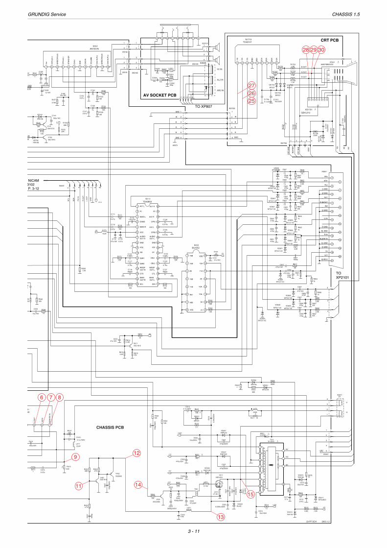
CHASSIS PCB
1K
R338
10u/16V
C334
2W150
R414
100u/35V
C414
4011
1
0.82R413
0.22uC415
1R411
0.1u/100V
C416
22uHL411
6.8uC522
600uHL5213900p/500V
C5014.7kR453
1500
p
C45
1
1000p/500VC502
1KR503
2SC2383V501
100
R502
T501
47u/35VC503
2.7
R513
1
10K
R512
BAV21
VD511
10u/250VC542
470pC826
10KR827
N101BU4052
MTZJ7.5C
VD826MTZJ7.5C
VD836
name
value
1
XS1703
CRT PCB
SC
HVFO
542 3
HE
AT
ER
CR
T G
ND
200V
1
XS1702
CR
T G
ND
2
B3
IK
4 G
R5
GND6
TO XP2101
3 4 51 267 823 15 4
NICAM 3102P. 3-12
TO XP807
29 PF SCH
!
!
!
!
!
!
!
!
!
!
6 7 8
9
11
12
14
15
13
272625
28 29 30

GRUNDIG Service CHASSIS 1.5
3 - 12
NICAM
+
53 421
+
+ +
VDDD4VSSD4
3537 36
SYSCLK
34
FM INEXT R
3940 38
VREF2P2
43 42 41
EXT LVSSA3
44
VDDA3 P1
WS 32
SDA 30
SDO 31
28VDDD3
26CRESET
27VSSD3
SCL 29
R OUT2
VSSA14
VDDA13
N3102
TDA9874AH
NICAM DEMVDDD16
8 VDDD2
7 VSSD2
VSSD15
L OUT1 SLK 33
25SIF1
24VREF1
23SIF2
VDDA2VSSA2
212019 22
TEST1IREFTEST2
181716
XTALIADDR1 VTUNE
151413
XTALO
TP29
NICAM10
TP1
PCLK
11
12
ADDR2
+
+
IF DEMODURATOR
20SIFVIF1
19SIFVIF2
18VPTADJ3
17CVAGCTPLL4
16GNDCSAGC5
15VC02VOAF6
14VC01CAF7
8 CVP/2 AFC 13
9
10 QSS 11FM IN
V OUT T AGC 12
XS3102
R OUT
L OUT
SCL
GND3.3
R3129
47u/16VC3134
+5V
10R3130
+5V
1000C3102
G9251M 38.9P
FL3101
SAW FILTER
0.47C3131
22KR3101
22KR3102
1000C3101
XS3101
0.01C3136
1KR3103
V31012SC2216
100
R3131
SDA
FM IN
+5V+5V
10R3124
+5V
100
R3127
0.47C3129
100
R3125
10KR3126
10KR3128
1uC3128
0.1C3127
47C3126
0.47
C3125
+5V
0.01C3117
0.01C3116
0.47
C3118
0.47
C3119
2.2u
C3114
+5V
10
R311776MHZL3101
0.01
C3108
0.22C3109
10
R3116
2.2u
C3115
0.47
C3120
24.576MX3201
22KR3108
22K
R3107
8.2KR3122
NICAM PWB
0.22C3103 180
R3104
0.1C3104
2.2uC3106
2.2uC3105 470
R3105
N3101TDA9808
0.47C3135
0.47C3130 name
value
TO
CH
AS
SIS
PC
B
XS
201
TO
CH
AS
SIS
PC
BX
S23
1
1
3
4
22
3
1
5
7
6
8
4 - 1
GR
UN
DIG
Service
CH
AS
SIS
1.5ÄNDERUNGEN VORBEHALTEN / SUBJECT TO ALTERATION
ErsatzteillisteSpare Parts List
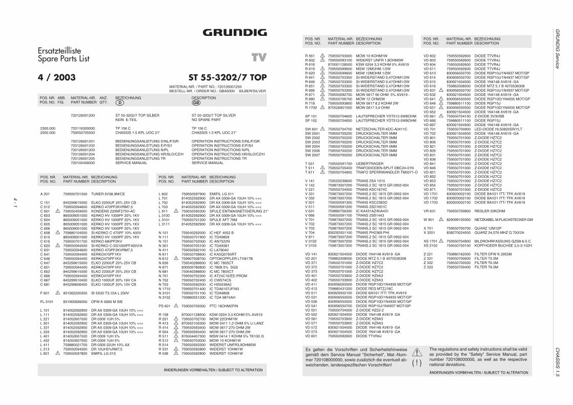
ST 55-3202/7 TOP
TV
MATERIAL-NR. / PART NO.: 720126001200BESTELL-NR. / ORDER NO.: GBA9300 SILBER/SILVER
�
4 / 2003
POS. NR. ABB. MATERIAL-NR. ANZ. BEZEICHNUNG DESCRIPTIONPOS. NO. FIG. PART NUMBER QTY. d ©
720126001200 ST 55-3202/7 TOP SILBER ST 55-3202/7 TOP SILVERKEIN E-TEIL NO SPARE PART
2300.000 720116300000 TP 156 C TP 156 C2500.000 759550705500 CHASSIS 1.5 KPL UOC 21" CHASSIS 1.5 KPL UOC 21"
720126001201 BEDIENUNGSANLEITUNG D/NL/F/GR OPERATION INSTRUCTIONS D/NL/F/GR720126001202 BEDIENUNGSANLEITUNG E/P/S/I OPERATION INSTRUCTIONS E/P/S/I720126001203 BEDIENUNGSANLEITUNG N/PL OPERATION INSTRUCTIONS N/PL720126001204 BEDIENUNGSANLEITUNG HR/SLO/CZ/H OPERATION INSTRUCTIONS HR/SLO/CZ/H720126001205 BEDIENUNGSANLEITUNG TR OPERATION INSTRUCTIONS TR720100456000 SERVICE MANUAL SERVICE MANUAL
A 201 759550701500 TUNER 5V38.9M/CE
C 151 845299615000 ELKO 2200UF 20% 25V CBC 512 759550594600 KERKO 470PF2KVRM7,5C 601 S 759550459000 KONDENS 220NF275V-ACC 603 865009051000 KERKO HV 1000PF 20% 1KVC 604 865009051000 KERKO HV 1000PF 20% 1KVC 605 865009051000 KERKO HV 1000PF 20% 1KVC 606 865009051000 KERKO HV 1000PF 20% 1KVC 608 S 759880104500 SI-KERKO C 470PF 10% 400VC 615 865009051000 KERKO HV 1000PF 20% 1KVC 616 759550701700 KERKO 680PF2KVC 620 S 759550594500 SI-KERKO C-SS1000PF400V/AC 631 759550594600 KERKO 470PF2KVRM7,5C 641 759550594400 KERKO470PF1KVC 646 759550594400 KERKO470PF1KVC 647 845299615000 ELKO 2200UF 20% 25V CBC 651 759550594400 KERKO470PF1KVC 652 845299615000 ELKO 2200UF 20% 25V CBC 666 759550594400 KERKO470PF1KVC 667 845299510400 ELKO 1000UF 20% 16V CAC 681 845299606400 ELKO 1000UF 20% 10V CB
F 601 S 831562200300 SI 5X20 T3,15A L 250V
FL 3101 831900926000 OFW K 9260 M SIE
L 101 814052592900 DR AX 0309-GA 10UH 10% <<<L 111 814052592900 DR AX 0309-GA 10UH 10% <<<L 221 814052607500 DR 0309 1UH 5%L 301 814052592900 DR AX 0309-GA 10UH 10% <<<L 331 814052592900 DR AX 0309-GA 10UH 10% <<<L 333 814052592900 DR AX 0309-GA 10UH 10% <<<L 401 814052607500 DR 0309 1UH 5%L 402 814052607500 DR 0309 1UH 5%L 411 759880021700 DR 0309 22UH 10% AXL 513 759550594000 DR 15UH5%RM7;5L 601 S 759550597800 EMIFIL LG 013
L 602 759550597900 EMIFIL LG 011L 701 814052592900 DR AX 0309-GA 10UH 10% <<<L 702 814052592900 DR AX 0309-GA 10UH 10% <<<L 703 814052592900 DR AX 0309-GA 10UH 10% <<<L 911 S 759550590300 SPULE ENTMAGNETISIERUNG 21"L 3100 814052592900 DR AX 0309-GA 10UH 10% <<<L 3101 759550701200 SPULE AFT 76ML 3111 814052592900 DR AX 0309-GA 10UH 10% <<<
N 101 759540292000 IC HEF 4052 BN 111 759550701900 IC TDA9859N 151 759550702000 IC AN7522NN 301 759550705100 IC TDA9361N 411 759550592100 IC LA78040N 611 759550706600 IC KA5Q0765RTN 612 S 759907008700 OPTOKOPPLER LTV817BN 656 759540286600 IC MC 7805CTN 671 830500780800 IC 7808 5% SGSN 681 759540286600 IC MC 7805CTN 701 759550702300 IC AT24C16/EE-PROMN 702 759550702400 IC CW574CSN 703 759550592500 IC HS0038A2N 1710 759550701400 IC TDA6107JF/N3N 3101 759550701100 IC TDA9808N 3102 759880551200 IC TDA 9874AH
PS 601 S 759550705000 PTC 18OHM2PIN
R 158 870001128500 KSW 0204 3,3 KOHM 5% AV619R 201 S 759550702700 MOW 22OHM1WR 413 S 870552100300 MOW 0411 1,2 OHM 5% LI LANZR 414 S 759550593400 MOW 0617 270 OHM 2WR 504 S 759550593400 MOW 0617 270 OHM 2WR 511 S 876504407300 MSW 0414 1 KOHM 5% TK100 /0R 512 S 759550703000 MOW 10 KOHM1WR 514 759550593300 WIDERST UNFR3,9OHM5WR 531 S 759550592800 WIDERST 1OHM1WR 536 S 759550592800 WIDERST 1OHM1W
POS. NR. MATERIAL-NR. BEZEICHNUNGPOS. NO. PART NUMBER DESCRIPTION
POS. NR. MATERIAL-NR. BEZEICHNUNGPOS. NO. PART NUMBER DESCRIPTION
POS. NR. MATERIAL-NR. BEZEICHNUNGPOS. NO. PART NUMBER DESCRIPTION
POS. NR. MATERIAL-NR. BEZEICHNUNGPOS. NO. PART NUMBER DESCRIPTION
ÄNDERUNGEN VORBEHALTEN / SUBJECT TO ALTERATION
( ! )!Es gelten die Vorschriften und Sicherheitshinweise
gemäß dem Service Manual "Sicherheit", Mat.-Num-mer 720108000000, sowie zusätzlich die eventuell ab-weichenden, landesspezifischen Vorschriften!
The regulations and safety instructions shall be validas provided by the "Safety" Service Manual, partnumber 720108000000, as well as the respectivenational deviations.
R 561 S 759550703000 MOW 10 KOHM1WR 602 S 759550593100 WIDERST UNFR 1,8OHM5WR 616 870001128500 KSW 0204 3,3 KOHM 5% AV619R 619 S 759550599600 MSW 12MOHM 1/2WR 620 S 759550599600 MSW 12MOHM 1/2WR 641 S 759550703300 SI-WIDERSTAND 0,47OHM1/2WR 646 S 759550703300 SI-WIDERSTAND 0,47OHM1/2WR 651 S 759550703300 SI-WIDERSTAND 0,47OHM1/2WR 666 S 759550703300 SI-WIDERSTAND 0,47OHM1/2WR 671 S 759550592700 MOW 0617 56 OHM 5% AV619 -R 680 S 759550706700 MOW 12 OHM2WR 718 759550593800 MOW 0617 8,2 KOHM 2WR 1709 S 870526901500 MOW 0617 3,9 OHM
SP 101 759550704600 LAUTSPRECHER YDT512-5W8OHMSP 102 759550704600 LAUTSPRECHER YDT512-5W8OHM
SW 601 S 759550704700 NETZSCHALTER KDC-A0411CSW 2001 759550700200 DRUCKSCHALTER 5MMSW 2002 759550700200 DRUCKSCHALTER 5MMSW 2003 759550700200 DRUCKSCHALTER 5MMSW 2004 759550700200 DRUCKSCHALTER 5MMSW 2006 759550700200 DRUCKSCHALTER 5MMSW 2007 759550700200 DRUCKSCHALTER 5MM
T 501 759550591700 UEBERTRAGERT 511 S 759550705400 TRAFODIODEN-SPLIT DBC24-01NT 611 S 759550704800 TRAFO SPERRWANDLER TM0071-O
V 141 759550239600 TRANS 2SA 1015V 142 759873007200 TRANS.2 SC 1815 GR 0902-004V 221 759550704500 TRANS KSC1674CV 331 759873007200 TRANS.2 SC 1815 GR 0902-004V 332 759873007200 TRANS.2 SC 1815 GR 0902-004V 501 759550591300 TRANS KSC2383OV 511 759550591200 TRANS 2SD1651CV 631 759880756300 IC KA431AZ/KIA431V 666 759550591100 TRANS 2SB1443V 701 759873007200 TRANS.2 SC 1815 GR 0902-004V 702 759873007200 TRANS.2 SC 1815 GR 0902-004V 703 759873007200 TRANS.2 SC 1815 GR 0902-004V 704 830292001100 TRANS PH2369 PHIV 811 759873007200 TRANS.2 SC 1815 GR 0902-004V 3102 759873007200 TRANS.2 SC 1815 GR 0902-004V 3103 759873007200 TRANS.2 SC 1815 GR 0902-004
VD 141 830921504500 DIODE 1N4148 AV619 -GAVD 201 759862008000 DIODE MTZ 5,1 B 4070536308VD 371 759550701000 Z-DIODE HZ7C2VD 372 759550701000 Z-DIODE HZ7C2VD 373 759550701000 Z-DIODE HZ7C2VD 401 759550703900 Z-DIODE HZ9A3VD 402 759550703900 Z-DIODE HZ9A3VD 411 830956550500 DIODE RGP10D/1N4935 MOT/GPVD 412 759880431200 DIODE REG MTZJ18CVD 511 830920002100 DIODE BAV21 ITT/ TFK AV619VD 531 830956550500 DIODE RGP10D/1N4935 MOT/GPVD 536 830956550500 DIODE RGP10D/1N4935 MOT/GPVD 541 830956550700 DIODE RGP10J/1N4937 MOT/GPVD 551 759550704000 Z-DIODE HZ22-2VD 552 830921504500 DIODE 1N4148 AV619 -GAVD 561 759550703900 Z-DIODE HZ9A3VD 571 759550703900 Z-DIODE HZ9A3VD 572 830921504500 DIODE 1N4148 AV619 -GAVD 573 830921504500 DIODE 1N4148 AV619 -GAVD 601 759550592600 DIODE TTVR4J
VD 602 759550592600 DIODE TTVR4JVD 603 759550592600 DIODE TTVR4JVD 604 759550592600 DIODE TTVR4JVD 611 759550592600 DIODE TTVR4JVD 613 830956550700 DIODE RGP10J/1N4937 MOT/GPVD 614 830956550700 DIODE RGP10J/1N4937 MOT/GPVD 615 830921504500 DIODE 1N4148 AV619 -GAVD 616 759862008000 DIODE MTZ 5,1 B 4070536308VD 631 S 830956550700 DIODE RGP10J/1N4937 MOT/GPVD 632 830921504500 DIODE 1N4148 AV619 -GAVD 641 S 830956550500 DIODE RGP10D/1N4935 MOT/GPVD 646 S 759880511100 DIODE RGP15JVD 651 S 830956550500 DIODE RGP10D/1N4935 MOT/GPVD 652 830921504500 DIODE 1N4148 AV619 -GAVD 661 S 759550704100 Z-DIODE 3V3HSBVD 666 759880511100 DIODE RGP15JVD 667 830921504500 DIODE 1N4148 AV619 -GAVD 701 759550700900 LED-DIODE HL50820SR/YLTVD 702 830921504500 DIODE 1N4148 AV619 -GAVD 801 759550701000 Z-DIODE HZ7C2VD 806 759550701000 Z-DIODE HZ7C2VD 821 759550701000 Z-DIODE HZ7C2VD 826 759550701000 Z-DIODE HZ7C2VD 831 759550701000 Z-DIODE HZ7C2VD 836 759550701000 Z-DIODE HZ7C2VD 841 759550701000 Z-DIODE HZ7C2VD 846 759550701000 Z-DIODE HZ7C2VD 851 759550701000 Z-DIODE HZ7C2VD 852 759550701000 Z-DIODE HZ7C2VD 853 759550701000 Z-DIODE HZ7C2VD 854 759550701000 Z-DIODE HZ7C2VD 871 759550701000 Z-DIODE HZ7C2VD 1701 830920002100 DIODE BAV21 ITT/ TFK AV619VD 1702 830920002100 DIODE BAV21 ITT/ TFK AV619VD 1703 830920002100 DIODE BAV21 ITT/ TFK AV619
VR 631 759550700800 REGLER 20KOHM
W 901 S 829099100300 NETZKABEL M.FLACHSTECKER GW
X 701 759550700700 QUARZ 12M12PX 3201 838270024500 QUARZ 24,576 MHZ Q 700/2A
XS 1701 S 759550704900 BILDROHRFASSUNG GZS8-6-5 CXS 2102 759550700100 KOPFHOEER BUCHSE 3,5-3-102H
Z 221 759880162000 FILTER OFW K 2955MZ 331 759550700600 FILTER T5.5MZ 332 759550700500 FILTER T6.5MZ 333 759550700400 FILTER T6.0M

4 - 2
GR
UN
DIG
Service
CH
AS
SIS
1.5ÄNDERUNGEN VORBEHALTEN / SUBJECT TO ALTERATION
ErsatzteillisteSpare Parts List
STF 55-3232/7 TOP
TV
�
4 / 2003
POS. NR. ABB. MATERIAL-NR. ANZ. BEZEICHNUNG DESCRIPTIONPOS. NO. FIG. PART NUMBER QTY. d ©
720126001220 STF 55-3232/7 TOP SILVER STF 55-3232/7 TOP SILVERKEIN E-TEIL NO SPARE PART
2300.000 720116300000 TP 156 C TP 156 C2500.000 759550705300 CHASSIS 1.5 KPL UOC 21"FLAT CHASSIS 1.5 KPL UOC 21"FLAT
720126001201 BEDIENUNGSANLEITUNG D/NL/F/GR OPERATION INSTRUCTIONS D/NL/F/720126001202 BEDIENUNGSANLEITUNG E/P/S/I OPERATION INSTRUCTIONS E/P/S/I720126001203 BEDIENUNGSANLEITUNG N/PL OPERATION INSTRUCTIONS N/PL720126001204 BEDIENUNGSANLEITUNG HR/SLO/CZ/H OPERATION INSTRUCTIONS HR/SLO/CZ/H720126001205 BEDIENUNGSANLEITUNG TR OPERATION INSTRUCTIONS TR720100456000 SERVICE MANUAL SERVICE MANUAL
POS. NR. MATERIAL-NR. BEZEICHNUNGPOS. NO. PART NUMBER DESCRIPTION
POS. NR. MATERIAL-NR. BEZEICHNUNGPOS. NO. PART NUMBER DESCRIPTION
A 201 759550701500 TUNER 5V38.9M/CE
C 151 845299615000 ELKO 2200UF 20% 25V CBC 512 759550701700 KERKO 680PF2KVC 601 S 759550459000 KONDENS 220NF275V-ACC 603 865009051000 KERKO HV 1000PF 20% 1KVC 604 865009051000 KERKO HV 1000PF 20% 1KVC 605 865009051000 KERKO HV 1000PF 20% 1KVC 606 865009051000 KERKO HV 1000PF 20% 1KVC 608 S 759880104500 SI-KERKO C 470PF 10% 400VC 615 865009051000 KERKO HV 1000PF 20% 1KVC 616 759550701700 KERKO 680PF2KVC 620 S 759550594500 SI-KERKO C-SS1000PF400V/ACC 631 759550594600 KERKO 470PF2KVRM7,5C 641 759550594400 KERKO470PF1KVC 646 759550594400 KERKO470PF1KVC 647 845299615000 ELKO 2200UF 20% 25V CBC 651 759550594400 KERKO470PF1KVC 652 845299615000 ELKO 2200UF 20% 25V CBC 666 759550594400 KERKO470PF1KVC 667 845299510400 ELKO 1000UF 20% 16V CAC 681 845299606400 ELKO 1000UF 20% 10V CB
F 601 S 831562200300 SI 5X20 T3,15A L 250V
FL 3101 831900926000 OFW K 9260 M SIE
L 101 814052592900 DR AX 0309-GA 10UH 10% <<<L 111 814052592900 DR AX 0309-GA 10UH 10% <<<L 221 814052607500 DR 0309 1UH 5%L 301 814052592900 DR AX 0309-GA 10UH 10% <<<L 331 814052592900 DR AX 0309-GA 10UH 10% <<<L 333 814052592900 DR AX 0309-GA 10UH 10% <<<L 401 814052607500 DR 0309 1UH 5%L 402 814052607500 DR 0309 1UH 5%L 411 759880021700 DR 0309 22UH 10% AXL 513 759550706500 BRUECKENSPULEL 601 S 759550597800 EMIFIL LG 013L 602 759550597900 EMIFIL LG 011
MATERIAL-NR. / PART NO.: 720126001220BESTELL-NR. / ORDER NO.: GBA9100 SILVER
L 701 814052592900 DR AX 0309-GA 10UH 10% <<<L 702 814052592900 DR AX 0309-GA 10UH 10% <<<L 703 814052592900 DR AX 0309-GA 10UH 10% <<<L 911 S 759550590300 SPULE ENTMAGNETISIERUNG 21"L 3100 814052592900 DR AX 0309-GA 10UH 10% <<<L 3101 759550701200 SPULE AFT 76ML 3111 814052592900 DR AX 0309-GA 10UH 10% <<<
N 101 759540292000 IC HEF 4052 BN 111 759550701900 IC TDA9859N 151 759550702000 IC AN7522NN 301 759550705100 IC TDA9361N 411 759550592100 IC LA78040N 611 759550706600 IC KA5Q0765RTN 612 S 759907008700 OPTOKOPPLER LTV817BN 656 759540286600 IC MC 7805CTN 671 830500780800 IC 7808 5% SGSN 681 759540286600 IC MC 7805CTN 701 759550702300 IC AT24C16/EE-PROMN 702 759550702400 IC CW574CSN 703 759550592500 IC HS0038A2N 1710 759550701400 IC TDA6107JF/N3N 3101 759550701100 IC TDA9808N 3102 759880551200 IC TDA 9874AH
PS 601 S 759550705000 PTC 18OHM2PIN
R 158 870001128500 KSW 0204 3,3 KOHM 5% AV619R 201 S 759550702700 MOW 22OHM1WR 413 S 759550592800 WIDERST 1OHM1WR 414 S 759550446700 MSW 100 OHM5%2WR 504 S 759550593400 MOW 0617 270 OHM 2WR 511 S 876504407300 MSW 0414 1 KOHM 5% TK100 /0R 512 S 759550703000 MOW 10 KOHM1WR 514 759550593300 WIDERST UNFR3,9OHM5WR 531 S 759550592800 WIDERST 1OHM1WR 536 S 759550592800 WIDERST 1OHM1WR 561 S 759550703000 MOW 10 KOHM 1WR 602 S 759550593100 WIDERST UNFR 1,8OHM5W
POS. NR. MATERIAL-NR. BEZEICHNUNGPOS. NO. PART NUMBER DESCRIPTION
POS. NR. MATERIAL-NR. BEZEICHNUNGPOS. NO. PART NUMBER DESCRIPTION
ÄNDERUNGEN VORBEHALTEN / SUBJECT TO ALTERATION
( ! )!Es gelten die Vorschriften und Sicherheitshinweise
gemäß dem Service Manual "Sicherheit", Mat.-Num-mer 720108000000, sowie zusätzlich die eventuell ab-weichenden, landesspezifischen Vorschriften!
The regulations and safety instructions shall be validas provided by the "Safety" Service Manual, partnumber 720108000000, as well as the respectivenational deviations.
R 616 870001128500 KSW 0204 3,3 KOHM 5% AV619R 619 S 759550599600 MSW 12 MOHM 1/2WR 620 S 759550599600 MSW 12 MOHM 1/2WR 641 S 759550703300 SI-WIDERSTAND 0,47OHM1/2WR 646 S 759550703300 SI-WIDERSTAND 0,47OHM1/2WR 651 S 759550703300 SI-WIDERSTAND 0,47OHM1/2WR 666 S 759550703300 SI-WIDERSTAND 0,47OHM1/2WR 671 S 759550592700 MOW 0617 56 OHM 5% AV619 -R 680 S 759550706700 MOW 12 OHM2WR 718 759550593800 MOW 0617 8,2 KOHM 2WR 1709 S 850926901500 MOW 0619 3,9 OHM
SP 101 759550704600 LAUTSPRECHER YDT512-5W8OHMSP 102 759550704600 LAUTSPRECHER YDT512-5W8OHM
SW 601 S 759550704700 NETZSCHALTER KDC-A0411CSW 2001 759550700200 DRUCKSCHALTER 5MMSW 2002 759550700200 DRUCKSCHALTER 5MMSW 2003 759550700200 DRUCKSCHALTER 5MMSW 2004 759550700200 DRUCKSCHALTER 5MMSW 2006 759550700200 DRUCKSCHALTER 5MMSW 2007 759550700200 DRUCKSCHALTER 5MM
T 501 759550591700 UEBERTRAGERT 511 S 759550705200 TRAFODIODEN-SPLIT DBC25-01NT 611 S 759550704800 TRAFO SPERRWANDLER TM0071-O
V 141 759550239600 TRANS 2SA 1015V 142 759873007200 TRANS.2 SC 1815 GR 0902-004V 221 759550704500 TRANS KSC1674CV 331 759873007200 TRANS.2 SC 1815 GR 0902-004V 332 759873007200 TRANS.2 SC 1815 GR 0902-004V 501 759550591300 TRANS KSC2383OV 511 759550591200 TRANS 2SD1651CV 631 759880756300 IC KA431AZ/KIA431V 666 759550591100 TRANS 2SB1443V 701 759873007200 TRANS.2 SC 1815 GR 0902-004V 702 759873007200 TRANS.2 SC 1815 GR 0902-004V 703 759873007200 TRANS.2 SC 1815 GR 0902-004V 704 830292001100 TRANS PH2369 PHIV 811 759873007200 TRANS.2 SC 1815 GR 0902-004V 3102 759873007200 TRANS.2 SC 1815 GR 0902-004V 3103 759873007200 TRANS.2 SC 1815 GR 0902-004
VD 141 830921504500 DIODE 1N4148 AV619 -GAVD 201 759862008000 DIODE MTZ 5,1 B 4070536308VD 371 759550701000 Z-DIODE HZ7C2VD 372 759550701000 Z-DIODE HZ7C2VD 373 759550701000 Z-DIODE HZ7C2VD 401 759550703900 Z-DIODE HZ9A3VD 402 759550703900 Z-DIODE HZ9A3VD 411 830956550500 DIODE RGP10D/1N4935 MOT/GPVD 412 759880431200 DIODE REG MTZJ18CVD 511 830920002100 DIODE BAV21 ITT/ TFK AV619VD 531 830956550500 DIODE RGP10D/1N4935 MOT/GPVD 536 830956550500 DIODE RGP10D/1N4935 MOT/GPVD 541 830956550700 DIODE RGP10J/1N4937 MOT/GPVD 551 759550704000 Z-DIODE HZ22-2VD 552 830921504500 DIODE 1N4148 AV619 -GAVD 561 759550703900 Z-DIODE HZ9A3VD 571 759550703900 Z-DIODE HZ9A3VD 572 830921504500 DIODE 1N4148 AV619 -GAVD 573 830921504500 DIODE 1N4148 AV619 -GAVD 601 759550592600 DIODE TTVR4JVD 602 759550592600 DIODE TTVR4JVD 603 759550592600 DIODE TTVR4J
VD 604 759550592600 DIODE TTVR4JVD 611 759550592600 DIODE TTVR4JVD 613 830956550700 DIODE RGP10J/1N4937 MOT/GPVD 614 830956550700 DIODE RGP10J/1N4937 MOT/GPVD 615 830921504500 DIODE 1N4148 AV619 -GAVD 616 759862008000 DIODE MTZ 5,1 B 4070536308VD 631 S 830956550700 DIODE RGP10J/1N4937 MOT/GPVD 632 830921504500 DIODE 1N4148 AV619 -GAVD 641 S 830956550500 DIODE RGP10D/1N4935 MOT/GPVD 646 S 759880511100 DIODE RGP15JVD 651 S 830956550500 DIODE RGP10D/1N4935 MOT/GPVD 652 830921504500 DIODE 1N4148 AV619 -GAVD 661 759550704100 Z-DIODE 3V3HSBVD 666 S 759880511100 DIODE RGP15JVD 667 830921504500 DIODE 1N4148 AV619 -GAVD 701 759550700900 LED-DIODE HL50820SR/YLTVD 702 830921504500 DIODE 1N4148 AV619 -GAVD 801 759550701000 Z-DIODE HZ7C2VD 806 759550701000 Z-DIODE HZ7C2VD 821 759550701000 Z-DIODE HZ7C2VD 826 759550701000 Z-DIODE HZ7C2VD 831 759550701000 Z-DIODE HZ7C2VD 836 759550701000 Z-DIODE HZ7C2VD 841 759550701000 Z-DIODE HZ7C2VD 846 759550701000 Z-DIODE HZ7C2VD 851 759550701000 Z-DIODE HZ7C2VD 852 759550701000 Z-DIODE HZ7C2VD 853 759550701000 Z-DIODE HZ7C2VD 854 759550701000 Z-DIODE HZ7C2VD 871 759550701000 Z-DIODE HZ7C2VD 1701 830920002100 DIODE BAV21 ITT/ TFK AV619VD 1702 830920002100 DIODE BAV21 ITT/ TFK AV619VD 1703 830920002100 DIODE BAV21 ITT/ TFK AV619
VR 631 759550700800 REGLER 20KOHM
W 901 S 829099100300 NETZKABEL M.FLACHSTECKER GW
X 701 759550700700 QUARZ 12M12PX 3201 838270024500 QUARZ 24,576 MHZ Q 700/2A
XS 1701 S 759550704900 BILDROHRFASSUNG GZ58-656
XS 2102 759550700100 KOPFHOEER BUCHSE 3,5-3-102H
Z 221 759880162000 FILTER OFW K 2955MZ 331 759550700600 FILTER T5.5MZ 332 759550700500 FILTER T6.5MZ 333 759550700400 FILTER T6.0M
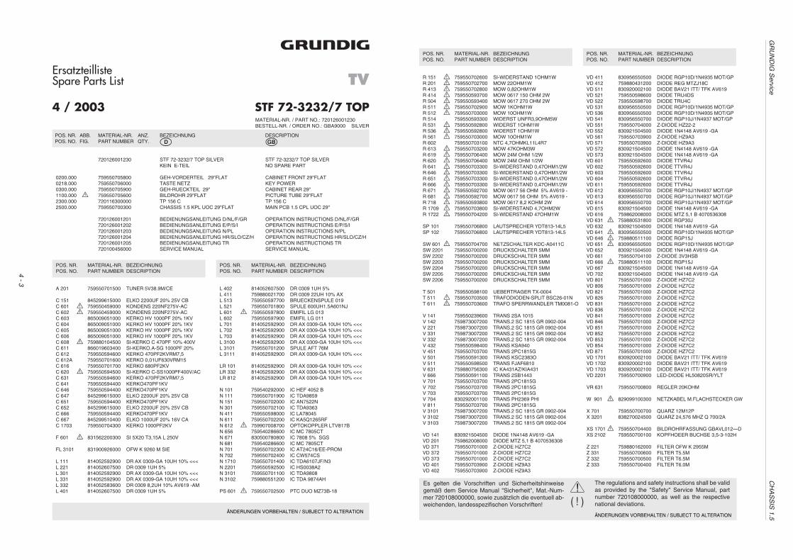
4 - 3
GR
UN
DIG
Service
CH
AS
SIS
1.5ÄNDERUNGEN VORBEHALTEN / SUBJECT TO ALTERATION
ErsatzteillisteSpare Parts List
STF 72-3232/7 TOP
TV
MATERIAL-NR. / PART NO.: 720126001230BESTELL-NR. / ORDER NO.: GBA9000 SILVER
�
4 / 2003
POS. NR. ABB. MATERIAL-NR. ANZ. BEZEICHNUNG DESCRIPTIONPOS. NO. FIG. PART NUMBER QTY. d ©
720126001230 STF 72-3232/7 TOP SILVER STF 72-3232/7 TOP SILVERKEIN E-TEIL NO SPARE PART
0200.000 759550705800 GEH-VORDERTEIL 29"FLAT CABINET FRONT 29"FLAT0218.000 759550706000 TASTE NETZ KEY POWER0300.000 759550705900 GEH-RUECKTEIL 29" CABINET REAR 29"1100.000 S 759550705600 BILDROHR 29"FLAT PICTURE TUBE 29"FLAT2300.000 720116300000 TP 156 C TP 156 C2500.000 759550700300 CHASSIS 1.5 KPL UOC 29"FLAT MAIN PCB 1.5 CPL UOC 29"
720126001201 BEDIENUNGSANLEITUNG D/NL/F/GR OPERATION INSTRUCTIONS D/NL/F/GR720126001202 BEDIENUNGSANLEITUNG E/P/S/I OPERATION INSTRUCTIONS E/P/S/I720126001203 BEDIENUNGSANLEITUNG N/PL OPERATION INSTRUCTIONS N/PL720126001204 BEDIENUNGSANLEITUNG HR/SLO/CZ/H OPERATION INSTRUCTIONS HR/SLO/CZ/H720126001205 BEDIENUNGSANLEITUNG TR OPERATION INSTRUCTIONS TR720100456000 SERVICE MANUAL SERVICE MANUAL
A 201 759550701500 TUNER 5V38.9M/CE
C 151 845299615000 ELKO 2200UF 20% 25V CBC 601 S 759550459000 KONDENS 220NF275V-ACC 602 S 759550459000 KONDENS 220NF275V-ACC 603 865009051000 KERKO HV 1000PF 20% 1KVC 604 865009051000 KERKO HV 1000PF 20% 1KVC 605 865009051000 KERKO HV 1000PF 20% 1KVC 606 865009051000 KERKO HV 1000PF 20% 1KVC 608 S 759880104500 SI-KERKO C 470PF 10% 400VC 611 866019603400 SI-KERKO.A-SG 1000PF 20%C 612 759550594600 KERKO 470PF2KVRM7,5C 612A 759550701600 KERKO 0,01UF630VRM15C 616 759550701700 KERKO 680PF2KVC 620 S 759550594500 SI-KERKO C-SS1000PF400V/ACC 631 759550594600 KERKO 470PF2KVRM7,5C 641 759550594400 KERKO470PF1KVC 646 759550594400 KERKO470PF1KVC 647 845299615000 ELKO 2200UF 20% 25V CBC 651 759550594400 KERKO470PF1KVC 652 845299615000 ELKO 2200UF 20% 25V CBC 666 759550594400 KERKO470PF1KVC 667 845299510400 ELKO 1000UF 20% 16V CAC 1703 759550704300 KERKO 1000PF2KV
F 601 S 831562200300 SI 5X20 T3,15A L 250V
FL 3101 831900926000 OFW K 9260 M SIE
L 111 814052592900 DR AX 0309-GA 10UH 10% <<<L 221 814052607500 DR 0309 1UH 5%L 301 814052592900 DR AX 0309-GA 10UH 10% <<<L 331 814052592900 DR AX 0309-GA 10UH 10% <<<L 332 814052583600 DR 0309 8,2UH 10% AV619 -AML 401 814052607500 DR 0309 1UH 5%
L 402 814052607500 DR 0309 1UH 5%L 411 759880021700 DR 0309 22UH 10% AXL 513 759550597700 BRUECKENSPULE 019L 521 759550701800 SPULE 600UH1.5A601NJL 601 S 759550597800 EMIFIL LG 013L 602 759550597900 EMIFIL LG 011L 701 814052592900 DR AX 0309-GA 10UH 10% <<<L 702 814052592900 DR AX 0309-GA 10UH 10% <<<L 703 814052592900 DR AX 0309-GA 10UH 10% <<<L 3100 814052592900 DR AX 0309-GA 10UH 10% <<<L 3101 759550701200 SPULE AFT 76ML 3111 814052592900 DR AX 0309-GA 10UH 10% <<<
LR 101 814052592900 DR AX 0309-GA 10UH 10% <<<LR 332 814052592900 DR AX 0309-GA 10UH 10% <<<LR 812 814052592900 DR AX 0309-GA 10UH 10% <<<
N 101 759540292000 IC HEF 4052 BN 111 759550701900 IC TDA9859N 151 759550702000 IC AN7522NN 301 759550702100 IC TDA9363N 411 759550598000 IC LA78045N 611 759550702200 IC KA5Q1265RFN 612 S 759907008700 OPTOKOPPLER LTV817BN 656 759540286600 IC MC 7805CTN 671 830500780800 IC 7808 5% SGSN 681 759540286600 IC MC 7805CTN 701 759550702300 IC AT24C16/EE-PROMN 702 759550702400 IC CW574CSN 1710 759550701400 IC TDA6107JF/N3N 2201 759550592500 IC HS0038A2N 3101 759550701100 IC TDA9808N 3102 759880551200 IC TDA 9874AH
PS 601 S 759550702500 PTC DUO MZ73B-18
POS. NR. MATERIAL-NR. BEZEICHNUNGPOS. NO. PART NUMBER DESCRIPTION
POS. NR. MATERIAL-NR. BEZEICHNUNGPOS. NO. PART NUMBER DESCRIPTION
POS. NR. MATERIAL-NR. BEZEICHNUNGPOS. NO. PART NUMBER DESCRIPTION
POS. NR. MATERIAL-NR. BEZEICHNUNGPOS. NO. PART NUMBER DESCRIPTION
R 151 S 759550702600 SI-WIDERSTAND 1OHM1WR 201 S 759550702700 MOW 22OHM1WR 413 S 759550702800 MOW 0,82OHM1WR 414 S 759550593700 MOW 0617 150 OHM 2WR 504 S 759550593400 MOW 0617 270 OHM 2WR 511 S 759550702900 MOW 1KOHM1WR 512 S 759550703000 MOW 10OHM1WR 514 759550593300 WIDERST UNFR3,9OHM5WR 531 S 759550592800 WIDERST 1OHM1WR 536 S 759550592800 WIDERST 1OHM1WR 561 S 759550703000 MOW 10OHM1WR 602 759550703100 NTC 4,7OHMKL11L4R7R 613 S 759550703200 MOW 47KOHM3WR 619 S 759550706400 MOW 24M OHM 1/2WR 620 S 759550706400 MOW 24M OHM 1/2WR 641 S 759550703300 SI-WIDERSTAND 0,47OHM1/2WR 646 S 759550703300 SI-WIDERSTAND 0,47OHM1/2WR 651 S 759550703300 SI-WIDERSTAND 0,47OHM1/2WR 666 S 759550703300 SI-WIDERSTAND 0,47OHM1/2WR 671 S 759550592700 MOW 0617 56 OHM 5% AV619 -R 681 S 759550592700 MOW 0617 56 OHM 5% AV619 -R 718 S 759550593800 MOW 0617 8,2 KOHM 2WR 1709 S 759550703800 SI-WIDERSTAND 4,7OHM2WR 1722 S 759550704200 SI-WIDERSTAND 47OHM1W
SP 101 759550706800 LAUTSPRECHER YDT813-14L5SP 102 759550706800 LAUTSPRECHER YDT813-14L5
SW 601 S 759550704700 NETZSCHALTER KDC-A0411CSW 2201 759550700200 DRUCKSCHALTER 5MMSW 2202 759550700200 DRUCKSCHALTER 5MMSW 2203 759550700200 DRUCKSCHALTER 5MMSW 2204 759550700200 DRUCKSCHALTER 5MMSW 2205 759550700200 DRUCKSCHALTER 5MMSW 2206 759550700200 DRUCKSCHALTER 5MM
T 501 759550598100 UEBERTRAGER TX-0004T 511 S 759550703500 TRAFODIODEN-SPLIT BSC26-01NT 611 S 759550703600 TRAFO SPERRWANDLER TM0081-O
V 141 759550239600 TRANS 2SA 1015V 142 759873007200 TRANS.2 SC 1815 GR 0902-004V 221 759873007200 TRANS.2 SC 1815 GR 0902-004V 331 759873007200 TRANS.2 SC 1815 GR 0902-004V 332 759873007200 TRANS.2 SC 1815 GR 0902-004V 432 759550598400 TRANS KSA940V 451 759550703700 TRANS 2PC1815GV 501 759550591300 TRANS KSC2383OV 511 759550598500 TRANS FJAF6810V 631 759880756300 IC KA431AZ/KIA431V 666 759550591100 TRANS 2SB1443V 701 759550703700 TRANS 2PC1815GV 702 759550703700 TRANS 2PC1815GV 703 759550703700 TRANS 2PC1815GV 704 830292001100 TRANS PH2369 PHIV 811 759550703700 TRANS 2PC1815GV 3101 759873007200 TRANS.2 SC 1815 GR 0902-004V 3102 759873007200 TRANS.2 SC 1815 GR 0902-004V 3103 759873007200 TRANS.2 SC 1815 GR 0902-004
VD 141 830921504500 DIODE 1N4148 AV619 -GAVD 201 759862008000 DIODE MTZ 5,1 B 4070536308VD 371 759550701000 Z-DIODE HZ7C2VD 372 759550701000 Z-DIODE HZ7C2VD 373 759550701000 Z-DIODE HZ7C2VD 401 759550703900 Z-DIODE HZ9A3VD 402 759550703900 Z-DIODE HZ9A3
VD 411 830956550500 DIODE RGP10D/1N4935 MOT/GPVD 412 759880431200 DIODE REG MTZJ18CVD 511 830920002100 DIODE BAV21 ITT/ TFK AV619VD 521 759550598600 DIODE TRU4DSVD 522 759550598700 DIODE TRU4CVD 531 830956550500 DIODE RGP10D/1N4935 MOT/GPVD 536 830956550500 DIODE RGP10D/1N4935 MOT/GPVD 541 830956550700 DIODE RGP10J/1N4937 MOT/GPVD 551 759550704000 Z-DIODE HZ22-2VD 552 830921504500 DIODE 1N4148 AV619 -GAVD 561 759550703900 Z-DIODE HZ9A3VD 571 759550703900 Z-DIODE HZ9A3VD 572 830921504500 DIODE 1N4148 AV619 -GAVD 573 830921504500 DIODE 1N4148 AV619 -GAVD 601 759550592600 DIODE TTVR4JVD 602 759550592600 DIODE TTVR4JVD 603 759550592600 DIODE TTVR4JVD 604 759550592600 DIODE TTVR4JVD 611 759550592600 DIODE TTVR4JVD 612 830956550700 DIODE RGP10J/1N4937 MOT/GPVD 613 830956550700 DIODE RGP10J/1N4937 MOT/GPVD 614 830956550700 DIODE RGP10J/1N4937 MOT/GPVD 615 830921504500 DIODE 1N4148 AV619 -GAVD 616 759862008000 DIODE MTZ 5,1 B 4070536308VD 631 S 759880531800 DIODE RGP30JVD 632 830921504500 DIODE 1N4148 AV619 -GAVD 641 S 830956550500 DIODE RGP10D/1N4935 MOT/GPVD 646 S 759880511100 DIODE RGP15JVD 651 S 830956550500 DIODE RGP10D/1N4935 MOT/GPVD 652 830921504500 DIODE 1N4148 AV619 -GAVD 661 759550704100 Z-DIODE 3V3HSBVD 666 S 759880511100 DIODE RGP15JVD 667 830921504500 DIODE 1N4148 AV619 -GAVD 702 830921504500 DIODE 1N4148 AV619 -GAVD 801 759550701000 Z-DIODE HZ7C2VD 806 759550701000 Z-DIODE HZ7C2VD 821 759550701000 Z-DIODE HZ7C2VD 826 759550701000 Z-DIODE HZ7C2VD 831 759550701000 Z-DIODE HZ7C2VD 836 759550701000 Z-DIODE HZ7C2VD 841 759550701000 Z-DIODE HZ7C2VD 846 759550701000 Z-DIODE HZ7C2VD 851 759550701000 Z-DIODE HZ7C2VD 852 759550701000 Z-DIODE HZ7C2VD 853 759550701000 Z-DIODE HZ7C2VD 854 759550701000 Z-DIODE HZ7C2VD 871 759550701000 Z-DIODE HZ7C2VD 1701 830920002100 DIODE BAV21 ITT/ TFK AV619VD 1702 830920002100 DIODE BAV21 ITT/ TFK AV619VD 1703 830920002100 DIODE BAV21 ITT/ TFK AV619VD 2201 759550700900 LED-DIODE HL50820SR/YLT
VR 631 759550700800 REGLER 20KOHM
W 901 S 829099100300 NETZKABEL M.FLACHSTECKER GW
X 701 759550700700 QUARZ 12M12PX 3201 838270024500 QUARZ 24,576 MHZ Q 700/2A
XS 1701 S 759550704400 BILDROHRFASSUNG GBAVL012—DXS 2102 759550700100 KOPFHOEER BUCHSE 3,5-3-102H
Z 221 759880162000 FILTER OFW K 2955MZ 331 759550700600 FILTER T5.5MZ 332 759550700500 FILTER T6.5MZ 333 759550700400 FILTER T6.0M
ÄNDERUNGEN VORBEHALTEN / SUBJECT TO ALTERATION
( ! )!Es gelten die Vorschriften und Sicherheitshinweise
gemäß dem Service Manual "Sicherheit", Mat.-Num-mer 720108000000, sowie zusätzlich die eventuell ab-weichenden, landesspezifischen Vorschriften!
The regulations and safety instructions shall be validas provided by the "Safety" Service Manual, partnumber 720108000000, as well as the respectivenational deviations.