cuj-c.qxd 08.5.29 7:24 am page 1 mini free mount cylinder · 2011. 3. 24. · mini free mount...
TRANSCRIPT
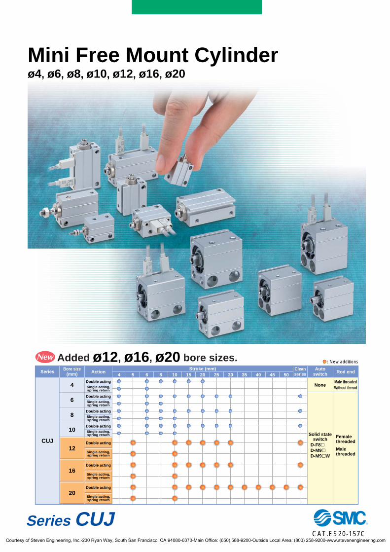
Series CUJ
Mini Free Mount Cylinderø4, ø6, ø8, ø10, ø12, ø16, ø20
ActionSeries
CUJ
Bore size(mm) Rod end
Stroke (mm) Cleanseries4 5 6 8 10 15 20 25 30 35 40 45 50
Male threadedWithout threadNone
Femalethreaded
Malethreaded
Solid stateswitch
Autoswitch
Double actingSingle acting,spring return
Double actingSingle acting,spring return
Double actingSingle acting,spring return
Double actingSingle acting,spring return
Double acting
Single acting,spring return
Double acting
Single acting,spring return
Double acting
Single acting,spring return
4
8
6
10
12
16
20
: New additionsAdded ø12, ø16, ø20 bore sizes.
D-F8D-M9D-M9W
CAT.ES20-157C
CUJ-C.qxd 08.5.29 7:24 AM Page 1
Courtesy of Steven Engineering, Inc.-230 Ryan Way, South San Francisco, CA 94080-6370-Main Office: (650) 588-9200-Outside Local Area: (800) 258-9200-www.stevenengineering.com
Mini Free Mount Cylinder
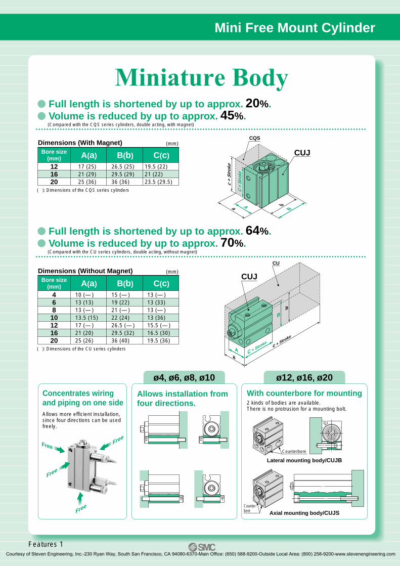
Miniature Body
C + Stroke
c + Stroke
b
Aa
B
CUJ
CU
ø4, ø6, ø8, ø10 ø12, ø16, ø20
Full length is shortened by up to approx. 20%. Volume is reduced by up to approx. 45%.
(Compared with the CQS series cylinders, double acting, with magnet)
Full length is shortened by up to approx. 64%. Volume is reduced by up to approx. 70%.
(Compared with the CU series cylinders, double acting, without magnet)
Dimensions (Without Magnet) (mm)
( ): Dimensions of the CU series cylinders
Bore size(mm)
46810121620
A(a) B(b) C(c)10 (— )13 (13)13 (— )13.5 (15)17 (— )21 (20)25 (26)
15 (— )19 (22)21 (— )22 (24)26.5 (— )29.5 (32)36 (40)
13 (— )13 (33)13 (— )13 (36)15.5 (— )16.5 (30)19.5 (36)
Dimensions (With Magnet) (mm)
( ): Dimensions of the CQS series cylinders
Bore size(mm)121620
A(a) B(b) C(c)17 (25)21 (29)25 (36)
26.5 (25)29.5 (29)36 (36)
19.5 (22)21 (22)23.5 (29.5)
Free
FreeFree
Free
Allows installation from four directions.
Allows more efficient installation, since four directions can be used freely.
With counterbore for mounting2 kinds of bodies are available.There is no protrusion for a mounting bolt.
BAa b
c +
Str
oke
C +
Stro
ke
CUJ
CQS
Axial mounting body/CUJS
Lateral mounting body/CUJB
Concentrates wiring and piping on one side
Counterbore
Counter-bore
Features 1
CUJ-C.qxd 08.5.29 7:24 AM Page 2
Courtesy of Steven Engineering, Inc.-230 Ryan Way, South San Francisco, CA 94080-6370-Main Office: (650) 588-9200-Outside Local Area: (800) 258-9200-www.stevenengineering.com
ø4, ø6, ø8, ø10 ø12, ø16, ø20
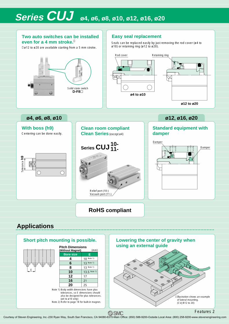
Series CUJ ø4, ø6, ø8, ø10, ø12, ø16, ø20
Two auto switches can be installed even for a 4 mm stroke.∗ ∗ ø12 to ø20 are available starting from a 5 mm stroke.
Solid state switchD-F8
Easy seal replacementSeals can be replaced easily by just removing the rod cover (ø4 to ø10) or retaining ring (ø12 to ø20).
With boss (h9)Centering can be done easily.
Tole
ranc
e h
9
Standard equipment withdamper
10-11-Series CUJ
Clean room compliantClean Series (except ø4)
RoHS compliant
Applications
Short pitch mounting is possible. Lowering the center of gravity when using an external guide
E
Note 1) Body width dimensions have plus tolerances, so E dimensions should also be designed for plus tolerances. (ø4 to ø10 only)
Note 2) Refer to page 18 for built-in magnet.
(mm)Pitch Dimensions (Without Magnet)
Bore size46810121620
E10 Note 1)
13 Note 1)
13 Note 1)
13.5 Note 1)
172125
Damper
Damper
Relief port (10-)Vacuum port (11-)
Rod cover
ø4 to ø10
ø12 to ø20
Retaining ring
∗ Illustration shows an example of lateral mounting. (CUJB12 to 20)
Features 2
CUJ-C.qxd 08.5.29 7:24 AM Page 3
Courtesy of Steven Engineering, Inc.-230 Ryan Way, South San Francisco, CA 94080-6370-Main Office: (650) 588-9200-Outside Local Area: (800) 258-9200-www.stevenengineering.com
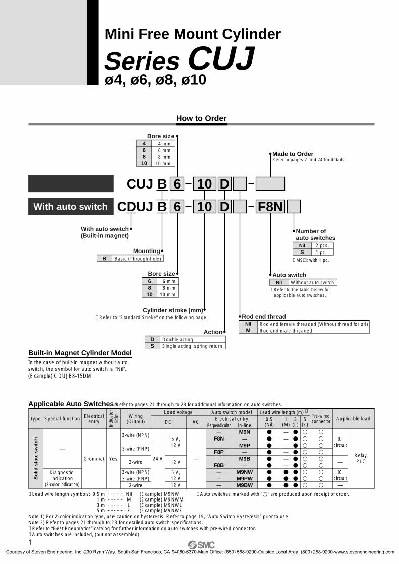
CDUJ B 6
6 D
D10
10
Basic (Through-hole)
MountingB
4 mm 6 mm 8 mm10 mm
Bore size46810
F8NWith auto switch
With auto switch(Built-in magnet)
6 mm 8 mm10 mm
Bore size6810
Cylinder stroke (mm)
ActionDouble actingSingle acting, spring return
DS
∗ Refer to the table below for applicable auto switches.
Auto switchWithout auto switchNil
Rod end female threaded (Without thread for ø4)Rod end male threaded
Rod end threadNilM
∗ Refer to “Standard Stroke” on the following page.
CUJ B
Made to Order Refer to pages 2 and 24 for details.
Built-in Magnet Cylinder ModelIn the case of built-in magnet without auto switch, the symbol for auto switch is “Nil”.(Example) CDUJB8-15DM
Special functionType Electricalentry
Wiring(Output)
Load voltage
ACDC
Auto switch modelElectrical entry
Lead wire length (m) ∗
0.5(Nil)
3(L)
5(Z)
Applicable load
Applicable Auto Switches/Refer to pages 21 through to 23 for additional information on auto switches.
∗ Lead wire length symbols: 0.5 m ············ Nil (Example) M9NW 1 m ············ M (Example) M9NWM 3 m ············ L (Example) M9NWL 5 m ············ Z (Example) M9NWZ
Note 1) For 2-color indication type, use caution on hysteresis. Refer to page 19, “Auto Switch Hysteresis” prior to use.Note 2) Refer to pages 21 through to 23 for detailed auto switch specifications.∗ Refer to “Best Pneumatics” catalog for further information on auto switches with pre-wired connector.∗ Auto switches are included, (but not assembled).
Perpendicular In-line
—
—
YesGrommet
Indi
cato
rlig
ht
3-wire (NPN)
2-wire
3-wire (NPN)3-wire (PNP)
2-wire
3-wire (PNP)
Pre-wired connector
∗ Auto switches marked with “” are produced upon receipt of order.
Relay,PLC
ICcircuit
ICcircuit
5 V,12 V
12 V
5 V,12 V12 V
24 V
M9N—
M9P—
M9B—
M9NWM9PWM9BW
—F8N—
F8P—
F8B———
—
—
Diagnostic indication
(2-color indication)
1(M)
——————
Mini Free Mount Cylinder
ø4, ø6, ø8, ø10Series CUJ
2 pcs.1 pc.
Number of auto switches
NilS
∗ M9: with 1 pc.
How to Order
So
lid s
tate
sw
itch
1
CUJ-C.qxd 08.5.29 7:24 AM Page 4
Courtesy of Steven Engineering, Inc.-230 Ryan Way, South San Francisco, CA 94080-6370-Main Office: (650) 588-9200-Outside Local Area: (800) 258-9200-www.stevenengineering.com
JIS Symbol
Unit: g
Double acting, single rod
Single acting, spring return
INSpring in pre-loaded condition Spring in loaded condition
OUT
When the spring is contracted by applying air.When the spring is set in the cylinder.
OUT IN
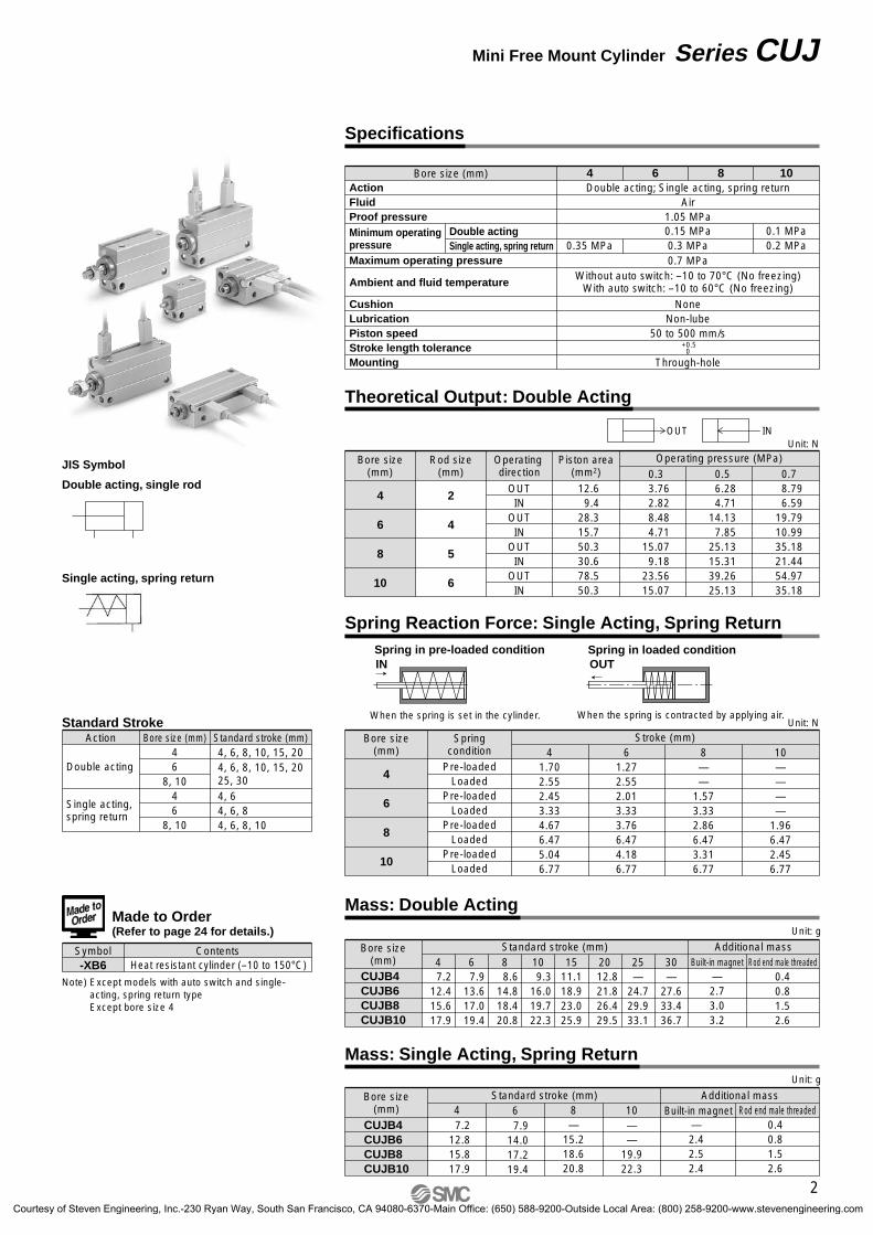
0.7 8.796.59
19.7910.9935.1821.4454.9735.18
0.5 6.284.71
14.137.85
25.1315.3139.2625.13
0.3 3.762.828.484.71
15.079.18
23.5615.07
Operating pressure (MPa)Unit: N
Operating direction
Piston area(mm2)
12.69.4
28.315.750.330.678.550.3
OUTIN
OUTIN
OUTIN
OUTIN
Rod size(mm)
Bore size(mm)
2
4
5
6
4
6
8
10
Bore size(mm)
CUJB4CUJB6CUJB8CUJB10
Standard stroke (mm)
7.212.415.617.9
7.913.617.019.4
4 6 8.614.818.420.8
8 109.3
16.019.722.3
1511.118.923.025.9
2012.821.826.429.5
25 30—2.73.03.2
Additional massBuilt-in magnet Rod end male threaded
0.40.81.52.6
—24.729.933.1
—27.633.436.7
ActionFluidProof pressure
Maximum operating pressure
CushionLubricationPiston speedStroke length toleranceMounting
Ambient and fluid temperature
Bore size (mm)
Minimum operating pressure
Double actingSingle acting, spring return
Double acting; Single acting, spring returnAir
1.05 MPa
4 6 8 10
0.1 MPa0.2 MPa
Without auto switch: –10 to 70°C (No freezing)With auto switch: –10 to 60°C (No freezing)
NoneNon-lube
50 to 500 mm/s
Through-hole
+0.50
0.7 MPa
0.15 MPa0.3 MPa0.35 MPa
Built-in magnet Rod end male threadedAdditional mass
—2.42.52.4
0.40.81.52.6
CUJB4CUJB6CUJB8CUJB10
Bore size(mm)
Standard stroke (mm)4 6 8 107.2
12.815.817.9
7.914.017.219.4
—15.218.620.8
——
19.922.3
Unit: g
Bore size (mm)46
8, 1046
8, 10
Action
Double acting
Single acting, spring return
Standard stroke (mm)Standard Stroke
Made to Order(Refer to page 24 for details.)
Symbol ContentsHeat resistant cylinder (–10 to 150°C)-XB6
Note) Except models with auto switch and single-acting, spring return typeExcept bore size 4
Specifications
Theoretical Output: Double Acting
Spring Reaction Force: Single Acting, Spring Return
Mass: Double Acting
Mass: Single Acting, Spring Return
Bore size(mm)
4
6
8
10
Springcondition
Pre-loadedLoaded
Pre-loadedLoaded
Pre-loadedLoaded
Pre-loadedLoaded
41.702.552.453.334.676.475.046.77
61.272.552.013.333.766.474.186.77
8——
1.573.332.866.473.316.77
10————
1.966.472.456.77
Stroke (mm)Unit: N
4, 6, 8, 10, 15, 20
4, 64, 6, 84, 6, 8, 10
4, 6, 8, 10, 15, 2025, 30
2
Mini Free Mount Cylinder Series CUJ
CUJ-C.qxd 08.5.29 7:24 AM Page 5
Courtesy of Steven Engineering, Inc.-230 Ryan Way, South San Francisco, CA 94080-6370-Main Office: (650) 588-9200-Outside Local Area: (800) 258-9200-www.stevenengineering.com
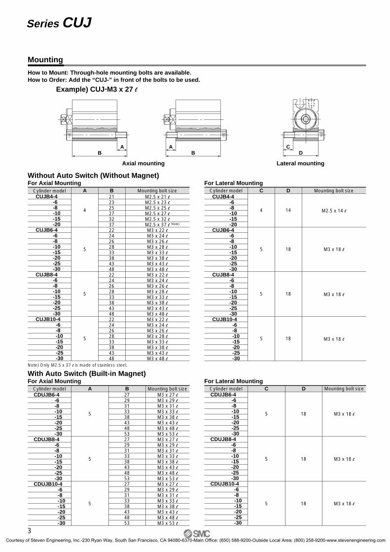
How to Mount: Through-hole mounting bolts are available.How to Order: Add the “CUJ-” in front of the bolts to be used.
Example) CUJ-M3 x 27 l
DCA
BA
B
Axial mounting Lateral mounting
C
4
5
5
5
D
14
18
18
18
M2.5 x 14 l
M3 x 18 l
M3 x 18 l
M3 x 18 l
Cylinder model Mounting bolt sizeCUJB4-4 -6 -8 -10 -15 -20CUJB6-4 -6 -8 -10 -15 -20 -25 -30CUJB8-4 -6 -8 -10 -15 -20 -25 -30CUJB10-4 -6 -8 -10 -15 -20 -25 -30
For Lateral Mounting
B272931333843485327293133384348532729313338434853
M3 x 27 lM3 x 29 lM3 x 31 lM3 x 33 lM3 x 38 lM3 x 43 lM3 x 48 lM3 x 53 lM3 x 27 lM3 x 29 lM3 x 31 lM3 x 33 lM3 x 38 lM3 x 43 lM3 x 48 lM3 x 53 lM3 x 27 lM3 x 29 lM3 x 31 lM3 x 33 lM3 x 38 lM3 x 43 lM3 x 48 lM3 x 53 l
A
5
5
5
Cylinder model Mounting bolt sizeCDUJB6-4 -6 -8 -10 -15 -20 -25 -30CDUJB8-4 -6 -8 -10 -15 -20 -25 -30CDUJB10-4 -6 -8 -10 -15 -20 -25 -30
For Axial MountingWith Auto Switch (Built-in Magnet)
D
18
18
18
M3 x 18 l
M3 x 18 l
M3 x 18 l
C
5
5
5
Cylinder model Mounting bolt sizeCDUJB6-4 -6 -8 -10 -15 -20 -25 -30CDUJB8-4 -6 -8 -10 -15 -20 -25 -30CDUJB10-4 -6 -8 -10 -15 -20 -25 -30
For Lateral Mounting
Without Auto Switch (Without Magnet)
B212325273237222426283338434822242628333843482224262833384348
M2.5 x 21 lM2.5 x 23 lM2.5 x 25 lM2.5 x 27 lM2.5 x 32 lM2.5 x 37 lM3 x 22 lM3 x 24 lM3 x 26 lM3 x 28 lM3 x 33 lM3 x 38 lM3 x 43 lM3 x 48 lM3 x 22 lM3 x 24 lM3 x 26 lM3 x 28 lM3 x 33 lM3 x 38 lM3 x 43 lM3 x 48 lM3 x 22 lM3 x 24 lM3 x 26 lM3 x 28 lM3 x 33 lM3 x 38 lM3 x 43 lM3 x 48 l
A
4
5
5
5
Cylinder model Mounting bolt sizeCUJB4-4 -6 -8 -10 -15 -20CUJB6-4 -6 -8 -10 -15 -20 -25 -30CUJB8-4 -6 -8 -10 -15 -20 -25 -30CUJB10-4 -6 -8 -10 -15 -20 -25 -30
For Axial Mounting
Note)
Note) Only M2.5 x 37 l is made of stainless steel.
Mounting
3
Series CUJ
CUJ-C.qxd 08.5.29 7:24 AM Page 6
Courtesy of Steven Engineering, Inc.-230 Ryan Way, South San Francisco, CA 94080-6370-Main Office: (650) 588-9200-Outside Local Area: (800) 258-9200-www.stevenengineering.com
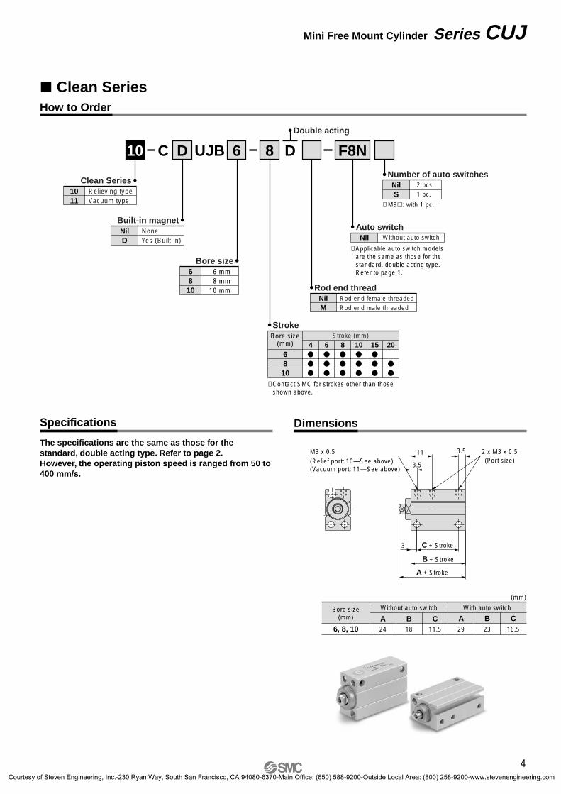
Clean Series
10 6Double acting
8 DC D UJB
Clean Series1011
Relieving typeVacuum type
Built-in magnetNil None
Yes (Built-in)D
Rod end threadNil Rod end female threaded
Rod end male threadedM
Number of auto switchesNil 2 pcs.
1 pc.S
6 mm8 mm
10 mm
Bore size6810
F8N
∗ Applicable auto switch models are the same as those for the standard, double acting type. Refer to page 1.
Auto switchNil Without auto switch
Without auto switch With auto switch
A B C A B C24 18 29 2311.5 16.56, 8, 10
Bore size(mm)
(mm)
2 x M3 x 0.5(Port size)
M3 x 0.5(Relief port: 10—See above)(Vacuum port: 11—See above)
3 C + Stroke
B + Stroke
A + Stroke
3.5
11 3.5
Bore size(mm)
Stroke (mm)4
6
8
10
15
20
6810
Stroke
∗ Contact SMC for strokes other than those shown above.
How to Order
Specifications Dimensions
The specifications are the same as those for the standard, double acting type. Refer to page 2.However, the operating piston speed is ranged from 50 to 400 mm/s.
∗ M9: with 1 pc.
4
Mini Free Mount Cylinder Series CUJ
CUJ-C.qxd 08.5.29 7:24 AM Page 7
Courtesy of Steven Engineering, Inc.-230 Ryan Way, South San Francisco, CA 94080-6370-Main Office: (650) 588-9200-Outside Local Area: (800) 258-9200-www.stevenengineering.com
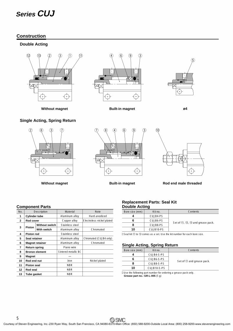
Double Acting
Single Acting, Spring Return
Without magnet
Rod end male threaded
ø4Built-in magnet
Built-in magnetWithout magnet
!3 w e q !1 r y o et
!2
u i r y o ew i e u !0
Replacement Parts: Seal KitDouble ActingComponent Parts
No. Description
Cylinder tube
Rod cover
Piston
Piston rod
Seal retainer
Magnet retainer
Return spring
Bronze element
Magnet
Rod end nut
Piston seal
Rod seal
Tube gasket
Material
Aluminum alloy
Copper alloy
Stainless steel
Aluminum alloy
Stainless steel
Aluminum alloy
Aluminum alloy
Piano wire
Sintered metallic BC
—
Iron
NBR
NBR
NBR
Note
Hard anodized
Electroless nickel plated
Chromated
Chromated (CUJB4 only)
Chromated
Nickel plated
1
2
3
4
5
6
7
8
9
10
11
12
13
Without switch
With switch
Kit no.
CUJB4-PS
CUJB6-PS
CUJB8-PS
CUJB10-PS
Bore size (mm)
46810
Contents
Set of !1, !2, !3 and grease pack.
∗ Seal kit !1 to !3 comes as a set. Use the kit number for each bore size.
Single Acting, Spring ReturnKit no.
CUJB4-S-PS
CUJB6-S-PS
CUJB8-S-PS
CUJB10-S-PS
Bore size (mm)
46810
Contents
Set of !1 and grease pack.
∗ Use the following part number for ordering a grease pack only.Grease part no.: GR-L-005 (5 g)
Construction
5
Series CUJ
CUJ-C.qxd 08.5.29 7:24 AM Page 8
Courtesy of Steven Engineering, Inc.-230 Ryan Way, South San Francisco, CA 94080-6370-Main Office: (650) 588-9200-Outside Local Area: (800) 258-9200-www.stevenengineering.com
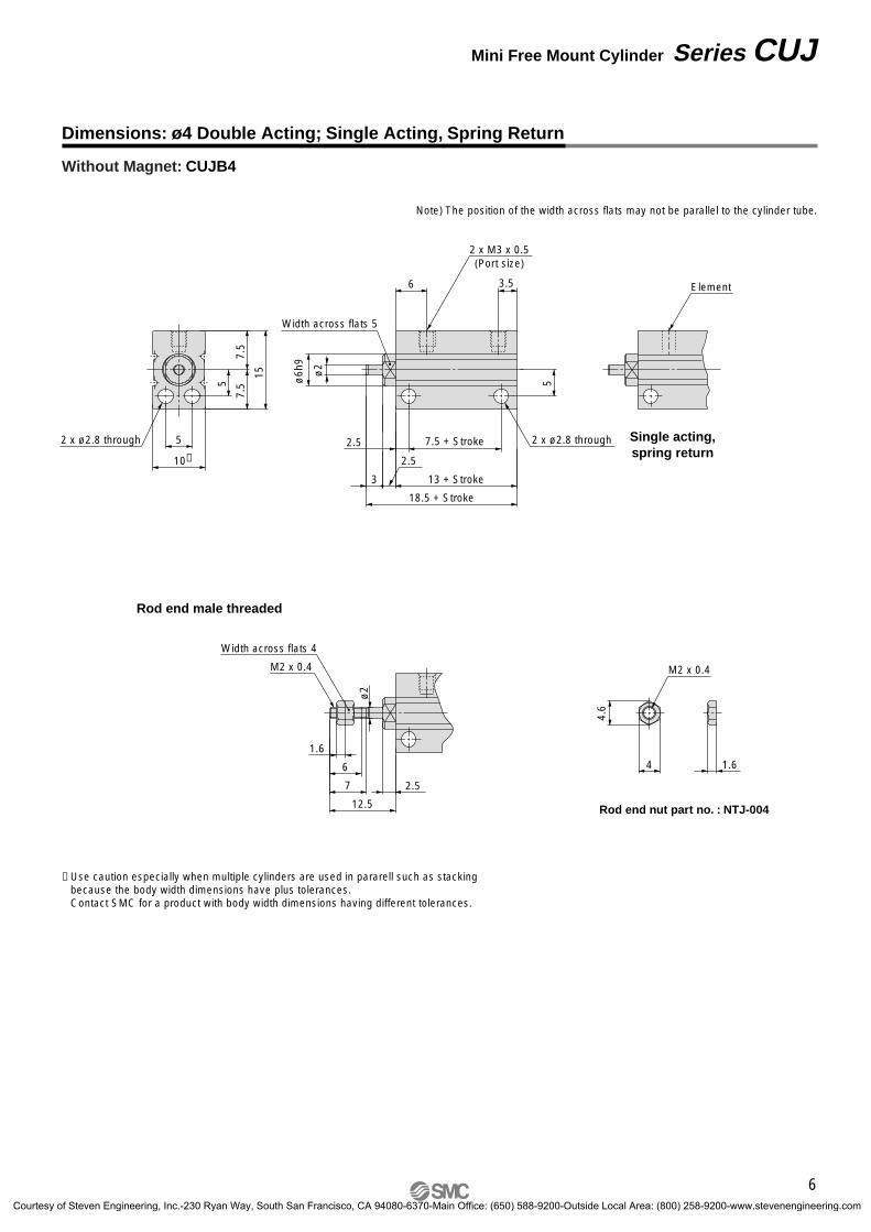
Without Magnet: CUJB4
12.5
7
6
1.6
ø2
M2 x 0.4
Width across flats 4
2.5
Element
Single acting,spring return
4.6
4
M2 x 0.4
1.6
Rod end nut part no. : NTJ-004
Rod end male threaded
Note) The position of the width across flats may not be parallel to the cylinder tube.
10∗
5
15
2 x ø2.8 through
18.5 + Stroke
13 + Stroke
6 3.5
7.5 + Stroke 2 x ø2.8 through
Width across flats 5
2 x M3 x 0.5(Port size)
2.5
7.5
7.55 5ø
6h9
ø2
2.5
3
∗ Use caution especially when multiple cylinders are used in pararell such as stacking because the body width dimensions have plus tolerances.Contact SMC for a product with body width dimensions having different tolerances.
Dimensions: ø4 Double Acting; Single Acting, Spring Return
6
Mini Free Mount Cylinder Series CUJ
CUJ-C.qxd 08.5.29 7:24 AM Page 9
Courtesy of Steven Engineering, Inc.-230 Ryan Way, South San Francisco, CA 94080-6370-Main Office: (650) 588-9200-Outside Local Area: (800) 258-9200-www.stevenengineering.com
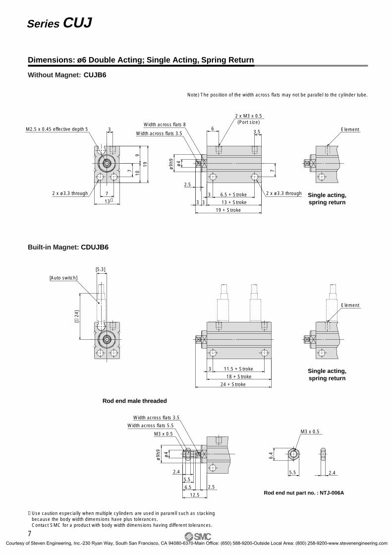
Without Magnet: CUJB6
Single acting,spring return
Single acting,spring return
Rod end nut part no. : NTJ-006A
Rod end male threaded
Element
12.5
6.5
5.5
2.4
ø4
ø9h
9
M3 x 0.5
Width across flats 5.5
Width across flats 3.5
2.5
5.5
6.4
M3 x 0.5
2.4
2 x ø3.3 through 2 x ø3.3 through
Width across flats 8
2 x M3 x 0.5(Port size)
13∗7
3
19
M2.5 x 0.45 effective depth 5
19 + Stroke
13 + Stroke
6.5 + Stroke3
63.5
ø4
ø9h
9
Width across flats 3.59
10
7 7
3
2.5
3
24 + Stroke
18 + Stroke
11.5 + Stroke3
[5.3]
[≈ 2
4]
[Auto switch]
Element
Note) The position of the width across flats may not be parallel to the cylinder tube.
Built-in Magnet: CDUJB6
∗ Use caution especially when multiple cylinders are used in pararell such as stacking because the body width dimensions have plus tolerances.Contact SMC for a product with body width dimensions having different tolerances.
Dimensions: ø6 Double Acting; Single Acting, Spring Return
7
Series CUJ
CUJ-C.qxd 08.5.29 7:24 AM Page 10
Courtesy of Steven Engineering, Inc.-230 Ryan Way, South San Francisco, CA 94080-6370-Main Office: (650) 588-9200-Outside Local Area: (800) 258-9200-www.stevenengineering.com
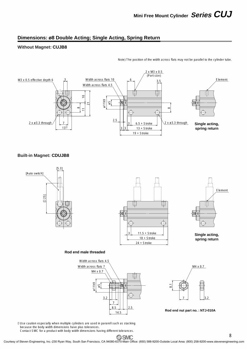
Without Magnet: CUJB8
Built-in Magnet: CDUJB8
Note) The position of the width across flats may not be parallel to the cylinder tube.
Single acting,spring return
Rod end male threaded
Single acting,spring return
Element
ø5
ø11
h9
14.5
8.5 2.5
7
3.2
M4 x 0.7
Width across flats 7
Width across flats 4.5
Rod end nut part no. : NTJ-010A
3.27
8.1
M4 x 0.7
2 x ø3.3 through 2 x ø3.3 through
Width across flats 10
2 x M3 x 0.5(Port size)
M3 x 0.5 effective depth 6
Width across flats 4.5
13∗7
3
21
19 + Stroke
13 + Stroke
6.5 + Stroke3
6 3.5
ø5
ø11
h9
1011
8 8
3
2.5
3
24 + Stroke
18 + Stroke
11.5 + Stroke3
[5.3]
[≈ 2
5]
[Auto switch]
Element
∗ Use caution especially when multiple cylinders are used in pararell such as stacking because the body width dimensions have plus tolerances.Contact SMC for a product with body width dimensions having different tolerances.
Dimensions: ø8 Double Acting; Single Acting, Spring Return
8
Mini Free Mount Cylinder Series CUJ
CUJ-C.qxd 08.5.29 7:24 AM Page 11
Courtesy of Steven Engineering, Inc.-230 Ryan Way, South San Francisco, CA 94080-6370-Main Office: (650) 588-9200-Outside Local Area: (800) 258-9200-www.stevenengineering.com
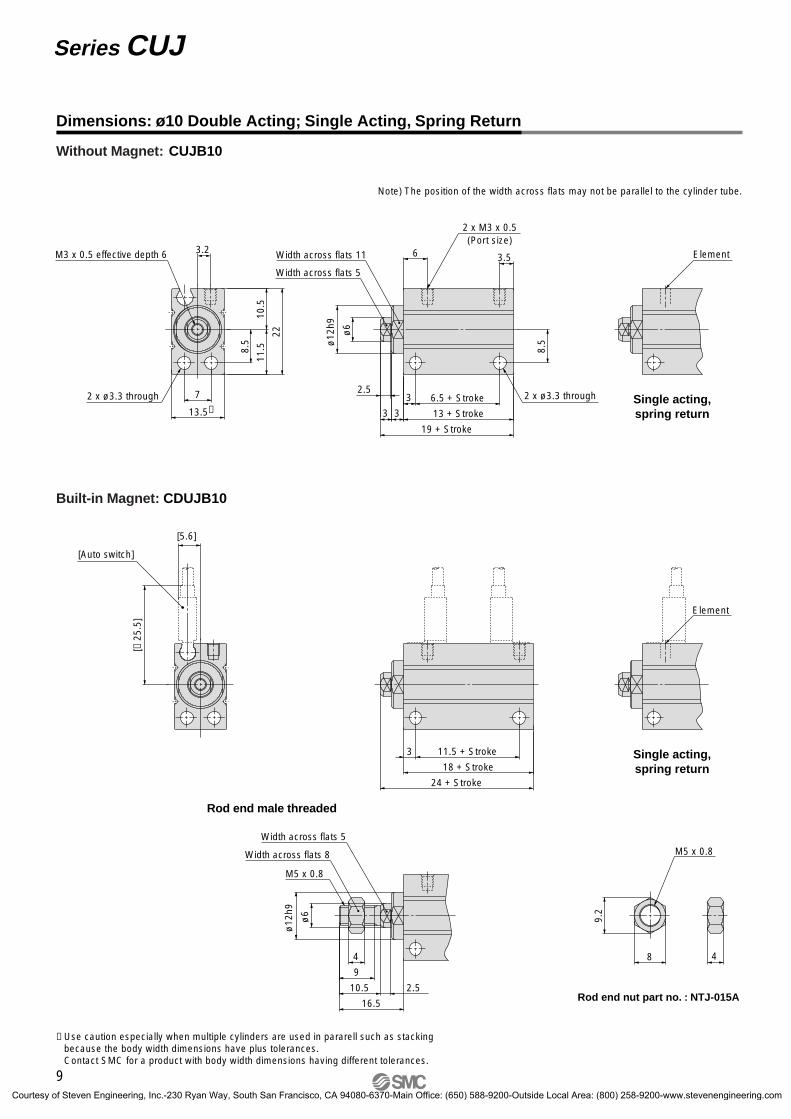
Without Magnet: CUJB10
Single acting,spring return
Single acting,spring return
Rod end nut part no. : NTJ-015A
Rod end male threaded
Element
ø6
ø12
h9
16.5
10.5
9
4
M5 x 0.8
Width across flats 8
Width across flats 5
48
9.2
M5 x 0.8
2 x ø3.3 through 2 x ø3.3 through
Width across flats 11
2 x M3 x 0.5(Port size)
M3 x 0.5 effective depth 6
Width across flats 5
13.5∗7
3.2
22
19 + Stroke
13 + Stroke
6.5 + Stroke3
6 3.5
ø6
ø12
h9
10.5
11.58.
5
8.5
3 3
24 + Stroke
18 + Stroke
11.5 + Stroke3
[5.6]
[≈ 2
5.5]
[Auto switch]
Element
2.5
2.5
Built-in Magnet: CDUJB10
Note) The position of the width across flats may not be parallel to the cylinder tube.
∗ Use caution especially when multiple cylinders are used in pararell such as stacking because the body width dimensions have plus tolerances.Contact SMC for a product with body width dimensions having different tolerances.
Dimensions: ø10 Double Acting; Single Acting, Spring Return
9
Series CUJ
CUJ-C.qxd 08.5.29 7:24 AM Page 12
Courtesy of Steven Engineering, Inc.-230 Ryan Way, South San Francisco, CA 94080-6370-Main Office: (650) 588-9200-Outside Local Area: (800) 258-9200-www.stevenengineering.com
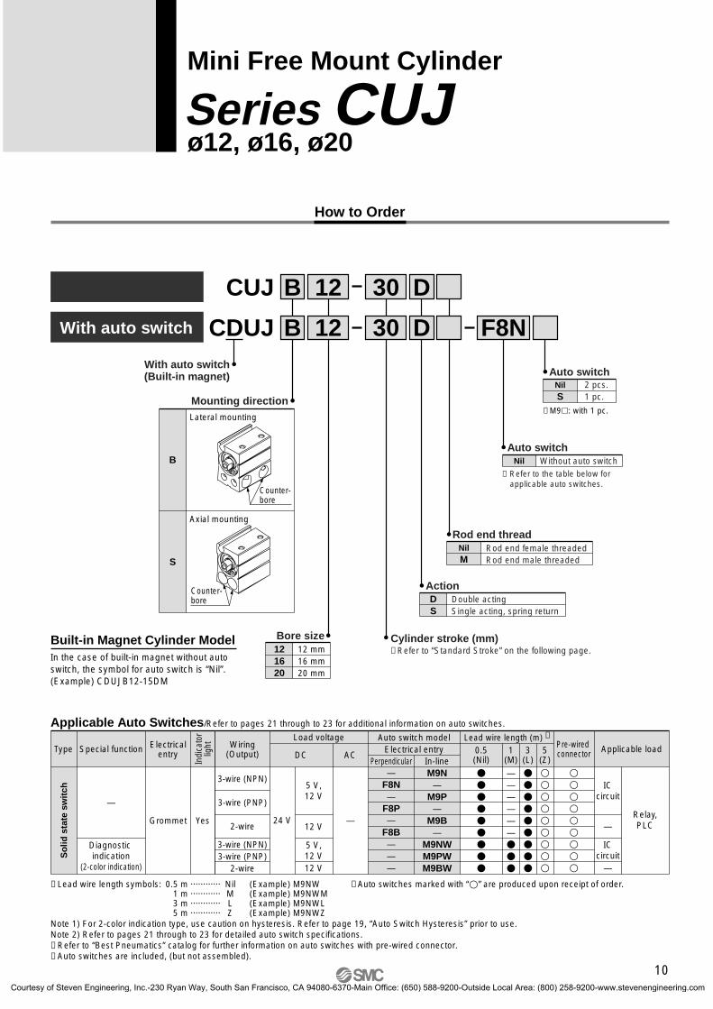
CDUJ 12
12 D
D30
30
F8NWith auto switch
With auto switch(Built-in magnet)
B
B
12 mm16 mm20 mm
Bore size121620
Cylinder stroke (mm)
ActionDouble actingSingle acting, spring return
DS
∗ Refer to the table below for applicable auto switches.
Auto switchWithout auto switchNil
Rod end female threadedRod end male threaded
Rod end threadNilM
∗ Refer to “Standard Stroke” on the following page.
CUJ
Wiring(Output)
Load voltage
ACDC
Auto switch modelElectrical entry
Lead wire length (m) ∗
0.5(Nil)
3(L)
5(Z)
Applicable load
Applicable Auto Switches/Refer to pages 21 through to 23 for additional information on auto switches.
∗ Lead wire length symbols: 0.5 m ············ Nil (Example) M9NW 1 m ············ M (Example) M9NWM 3 m ············ L (Example) M9NWL 5 m ············ Z (Example) M9NWZ
Note 1) For 2-color indication type, use caution on hysteresis. Refer to page 19, “Auto Switch Hysteresis” prior to use.Note 2) Refer to pages 21 through to 23 for detailed auto switch specifications.∗ Refer to “Best Pneumatics” catalog for further information on auto switches with pre-wired connector.∗ Auto switches are included, (but not assembled).
Perpendicular In-line
—
—
3-wire (NPN)
2-wire
3-wire (NPN)3-wire (PNP)
2-wire
3-wire (PNP)
Pre-wired connector
∗ Auto switches marked with “” are produced upon receipt of order.
Relay,PLC
ICcircuit
ICcircuit
5 V,12 V
12 V
5 V,12 V12 V
24 V
M9N—
M9P—
M9B—
M9NWM9PWM9BW
—F8N—
F8P—
F8B———
—
1(M)
——————
Mini Free Mount Cylinder
ø12, ø16, ø20Series CUJ
2 pcs.1 pc.
Auto switchNilS
∗ M9: with 1 pc.
Built-in Magnet Cylinder ModelIn the case of built-in magnet without auto switch, the symbol for auto switch is “Nil”.(Example) CDUJB12-15DM
Mounting directionLateral mounting
B
Axial mounting
S
Counter-bore
Counter-bore
How to Order
Special functionType Electricalentry
YesGrommet
Indi
cato
rlig
ht
—
Diagnostic indication
(2-color indication)
So
lid s
tate
sw
itch
10
CUJ-C.qxd 08.5.29 7:24 AM Page 13
Courtesy of Steven Engineering, Inc.-230 Ryan Way, South San Francisco, CA 94080-6370-Main Office: (650) 588-9200-Outside Local Area: (800) 258-9200-www.stevenengineering.com
Standard StrokeBore size (mm)Action Standard stroke (mm)
5, 10, 15, 2025, 30
5, 10, 15, 20, 2530, 35, 40, 45, 50
5, 10
Double acting
12
16
20
12
16
20
Single acting, spring return
JIS Symbol
Double acting, single rod
Single acting, spring return
OUT INUnit: N
0.70.50.3
79
59
141
106
220
165
57
42
101
75
157
118
34
25
60
45
94
71
Operating pressure (MPa)Operating direction
Piston area(mm2)
113
84.8
201
151
314
236
OUT
IN
OUT
IN
OUT
IN
Rod size(mm)
Bore size(mm)
6
8
10
12
16
20
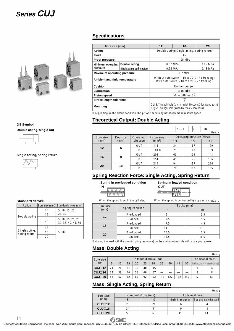
Theoretical Output: Double Acting
Unit: g
Bore size(mm)
CUJ12CUJ16CUJ20
Standard stroke (mm)
5 10 15 20 25 30 35 40 45 50
Additional mass
Built-in magnet Rod end male threaded
21
32
52
26
39
62
31
46
72
35
53
82
40
60
92
45
67
102
—
—
112
—
—
122
—
—
132
—
—
142
6
9
12
4
8
13
Mass: Double Acting
Unit: g
Built-in magnet Rod end male threaded
Additional mass
CUJ12CUJ16CUJ20
Bore size(mm)
Standard stroke (mm)
5 10
23
34
53
28
41
63
6
9
11
4
8
13
Mass: Single Acting, Spring Return
Bore size (mm)
Action
Fluid
Proof pressure
Maximum operating pressure
Cushion
Lubrication
Piston speed
Stroke length tolerance
Minimum operating pressure
Ambient and fluid temperature
Double acting
Single acting, spring return
Double acting; Single acting, spring return
Air
1.05 MPa
12 16
0.05 MPa
0.18 MPa
20
Without auto switch: –10 to 70°C (No freezing)With auto switch: –10 to 60°C (No freezing)
CUJB: Through-hole (lateral, axial direction: 2 locations each)CUJS: Through-hole (axial direction: 2 locations)
Rubber bumper
Non-lube
50 to 500 mm/s∗ +1.0
0
0.7 MPa
0.07 MPa
0.25 MPa
Mounting
Specifications
∗ Depending on the circuit condition, the piston speed may not reach the maximum speed.
Unit: N
Bore size(mm)
12
16
20
Spring condition
Pre-loaded
Loaded
Pre-loaded
Loaded
Pre-loaded
Loaded
5 10
6
9.5
7.5
11
10.5
16.5
3.5
9.5
4.5
11
5.5
16.5
Stroke (mm)
INSpring in pre-loaded condition Spring in loaded condition
OUT
When the spring is contracted by applying air.When the spring is set in the cylinder.
Spring Reaction Force: Single Acting, Spring Return
∗ Moving the load with the thrust (spring response) on the spring return side will cause poor stroke.
11
Series CUJ
CUJ-C.qxd 08.5.29 7:24 AM Page 14
Courtesy of Steven Engineering, Inc.-230 Ryan Way, South San Francisco, CA 94080-6370-Main Office: (650) 588-9200-Outside Local Area: (800) 258-9200-www.stevenengineering.com
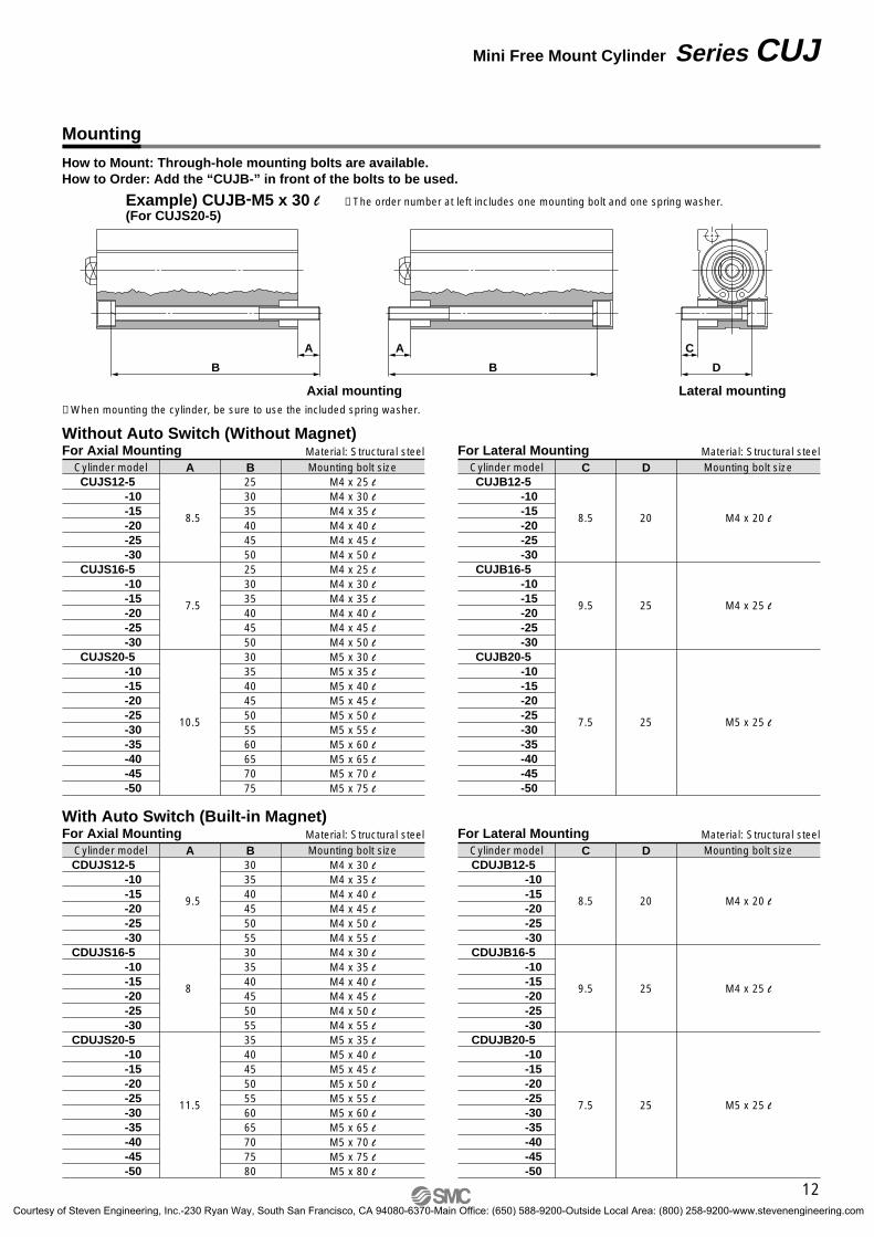
How to Mount: Through-hole mounting bolts are available.How to Order: Add the “CUJB-” in front of the bolts to be used.
Example) CUJB-M5 x 30 l(For CUJS20-5)
Mounting
Axial mounting Lateral mounting
Without Auto Switch (Without Magnet)
BM4 x 25 lM4 x 30 lM4 x 35 lM4 x 40 lM4 x 45 lM4 x 50 lM4 x 25 lM4 x 30 lM4 x 35 lM4 x 40 lM4 x 45 lM4 x 50 lM5 x 30 lM5 x 35 lM5 x 40 lM5 x 45 lM5 x 50 lM5 x 55 lM5 x 60 lM5 x 65 lM5 x 70 lM5 x 75 l
A
8.5
Cylinder model Mounting bolt sizeMaterial: Structural steel
∗ When mounting the cylinder, be sure to use the included spring washer.
∗ The order number at left includes one mounting bolt and one spring washer.
Material: Structural steel
Material: Structural steel Material: Structural steel
For Axial Mounting
CUJS12-5 -10-15-20-25-30
CUJS16-5 -10-15-20-25-30
CUJS20-5 -10-15-20-25-30-35-40-45-50
7.5
10.5
D
M4 x 20 l
C
8.5
Cylinder model Mounting bolt size
For Lateral Mounting
CUJB12-5 -10-15-20-25-30
CUJB16-5 -10-15-20-25-30
CUJB20-5 -10-15-20-25-30-35-40-45-50
9.5
7.5
20
25
25
M4 x 25 l
M5 x 25 l
D
M4 x 20 l
C
8.5
Cylinder model Mounting bolt size
For Lateral Mounting
CDUJB12-5 -10-15-20-25-30
CDUJB16-5 -10-15-20-25-30
CDUJB20-5 -10-15-20-25-30-35-40-45-50
9.5
7.5
20
25
25
M4 x 25 l
M5 x 25 l
B30354045505530354045505535404550556065707580
M4 x 30 lM4 x 35 lM4 x 40 lM4 x 45 lM4 x 50 lM4 x 55 lM4 x 30 lM4 x 35 lM4 x 40 lM4 x 45 lM4 x 50 lM4 x 55 lM5 x 35 lM5 x 40 lM5 x 45 lM5 x 50 lM5 x 55 lM5 x 60 lM5 x 65 lM5 x 70 lM5 x 75 lM5 x 80 l
A
9.5
Cylinder model Mounting bolt size
For Axial Mounting
CDUJS12-5 -10-15-20-25-30
CDUJS16-5 -10-15-20-25-30
CDUJS20-5 -10-15-20-25-30-35-40-45-50
8
11.5
With Auto Switch (Built-in Magnet)
A
B
A
B D
C
25303540455025303540455030354045505560657075
12
Mini Free Mount Cylinder Series CUJ
CUJ-C.qxd 08.5.29 7:24 AM Page 15
Courtesy of Steven Engineering, Inc.-230 Ryan Way, South San Francisco, CA 94080-6370-Main Office: (650) 588-9200-Outside Local Area: (800) 258-9200-www.stevenengineering.com
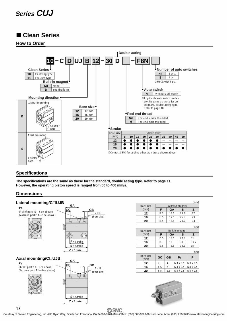
Clean Series
10 12Double acting
30 DC D UJClean Series1011
Relieving typeVacuum type
Built-in magnetNil None
Yes (Built-in)D
Rod end threadNil Rod end female threaded
Rod end male threadedM
Number of auto switchesNil 2 pcs.
1 pc.S
12 mm16 mm20 mm
Bore size121620
B F8N
∗ Applicable auto switch models are the same as those for the standard, double acting type. Refer to page 10.
Auto switchNil Without auto switch
(mm)
Bore size(mm)
Stroke (mm)5
10
15
20
25
30
35——
40——
45——
50——
121620
Stroke
∗ Contact SMC for strokes other than those shown above.
How to Order
Specifications
Dimensions
∗ M9: with 1 pc.
Mounting directionLateral mounting
B
Axial mounting
S
Counter-bore
Counter-bore
The specifications are the same as those for the standard, double acting type. Refer to page 11.However, the operating piston speed is ranged from 50 to 400 mm/s.
15.517.518.5
GA272934
23.525.529.5
11.513.515.5
ZSWithout magnet
F121620
Bore size(mm)
GC GB
Z + Stroke
S + Stroke
2 x P(Port size)
(Relief port: 10—See above)(Vacuum port: 11—See above)
P1
GAGC GB
Z + Stroke
S + Stroke
F + Stroke
2 x P(Port size)
(Relief port: 10—See above)(Vacuum port: 11—See above)
P1
(mm)
15.518 18.5
GA31 33.538
27.530 33.5
15.518 19.5
ZSBuilt-in magnet
F121620
Bore size(mm)
(mm)
4 4 5.5
GB
M3 x 0.5M3 x 0.5M5 x 0.8
M3 x 0.5M3 x 0.5M5 x 0.8
7 8.58.5
PP1GC
121620
Bore size(mm)
GA
Lateral mounting/CUJB
Axial mounting/CUJS
13
Series CUJ
CUJ-C.qxd 08.5.29 7:24 AM Page 16
Courtesy of Steven Engineering, Inc.-230 Ryan Way, South San Francisco, CA 94080-6370-Main Office: (650) 588-9200-Outside Local Area: (800) 258-9200-www.stevenengineering.com
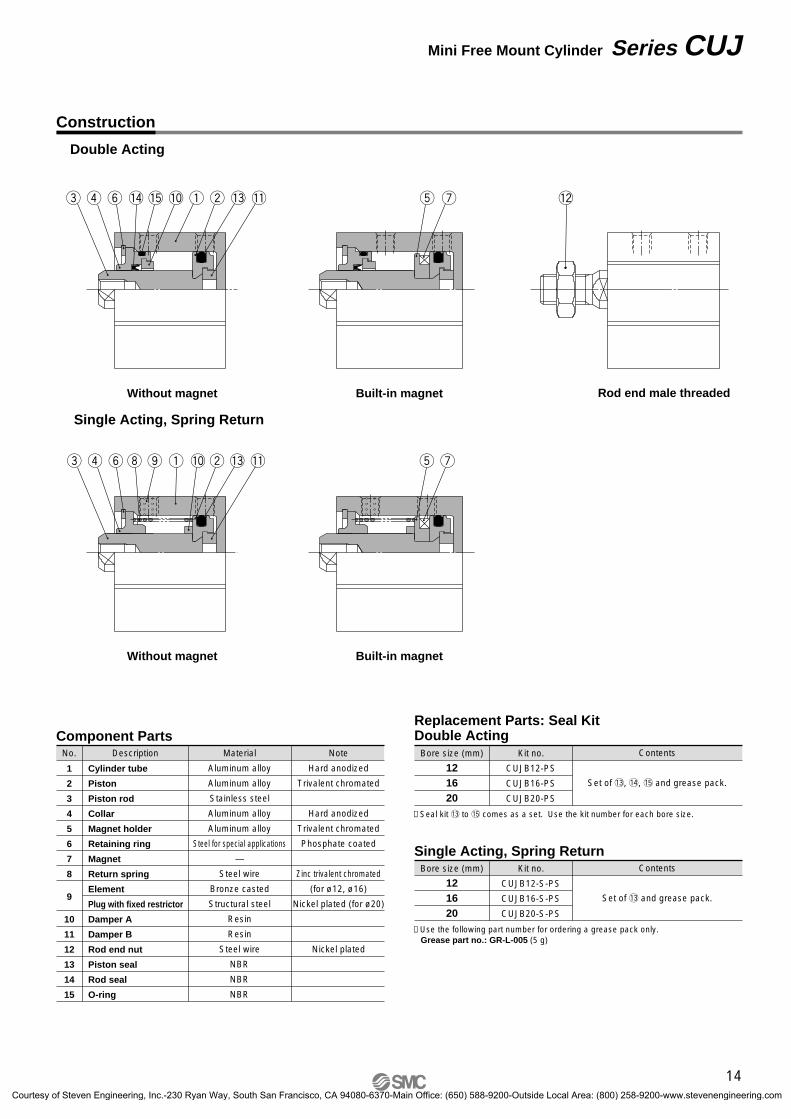
ut!1!0 !3wq!5!4yre !2
!1!0 !3wqoiyre ut
Construction
Double Acting
Single Acting, Spring Return
Without magnet Rod end male threadedBuilt-in magnet
Built-in magnetWithout magnet
Replacement Parts: Seal KitDouble ActingComponent Parts
No. Description
Cylinder tube
Piston
Piston rod
Collar
Magnet holder
Retaining ring
Magnet
Return spring
Element
Plug with fixed restrictor
Damper A
Damper B
Rod end nut
Piston seal
Rod seal
O-ring
Material
Aluminum alloy
Aluminum alloy
Stainless steel
Aluminum alloy
Aluminum alloy
Steel for special applications
—
Steel wire
Bronze casted
Structural steel
Resin
Resin
Steel wire
NBR
NBR
NBR
Note
Hard anodized
Trivalent chromated
Hard anodized
Trivalent chromated
Phosphate coated
Zinc trivalent chromated
(for ø12, ø16)
Nickel plated (for ø20)
Nickel plated
1
2
3
4
5
6
7
8
9
10
11
12
13
14
15
Kit no.
CUJB12-PS
CUJB16-PS
CUJB20-PS
Bore size (mm)
121620
Contents
Set of !3, !4, !5 and grease pack.
∗ Seal kit !3 to !5 comes as a set. Use the kit number for each bore size.
Single Acting, Spring ReturnKit no.
CUJB12-S-PS
CUJB16-S-PS
CUJB20-S-PS
Bore size (mm)
121620
Contents
Set of !3 and grease pack.
∗ Use the following part number for ordering a grease pack only.Grease part no.: GR-L-005 (5 g)
14
Mini Free Mount Cylinder Series CUJ
CUJ-C.qxd 08.5.29 7:24 AM Page 17
Courtesy of Steven Engineering, Inc.-230 Ryan Way, South San Francisco, CA 94080-6370-Main Office: (650) 588-9200-Outside Local Area: (800) 258-9200-www.stevenengineering.com
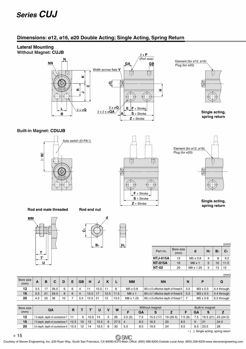
Element (for ø12, ø16)Plug (for ø20)
NN
2 x øQ
N
KC
JR
BL
Z + Stroke
S + Stroke
Auto switch (D-F8)
[≈ W
]
MM
T
UT'
Width across flats V
2 x øQ2 x 2 x øQA
F + Stroke
F + Stroke
GBGA
H
øD
Z + Stroke
A S + Stroke
E
2 x P(Port size)
Element (for ø12, ø16)Plug (for ø20)
H1
d
C1
B1
Single acting,spring return
Single acting,spring return
Lateral MountingWithout Magnet: CUJB
Built-in Magnet: CDUJB
Rod end male threaded Rod end nut
(mm)
121620
ABore size(mm)
3.5
3.5
4.5
B
17
21
25
C
26.5
29.5
36
D
6
8
10
N
3.5
5.5
7
GB
4
4
5.5
H
11
12.5
15.5
J
15.5
17
21
K
11
12.5
15
L
8
11.5
13.5
MM
M5 x 0.8
M6 x 1
M8 x 1.25
P
M3 x 0.5
M3 x 0.5
M5 x 0.8
Q
4.4 through
4.4 through
5.5 through
NN
M3 x 0.5 effective depth of thread 6
M4 x 0.7 effective depth of thread 8
M5 x 0.8 effective depth of thread 7
E
6
6
7
(mm)
NTJ-015ANT-015ANT-02
Part no.
12
16
20
Bore size(mm) d
M5 x 0.8
M6 x 1
M8 x 1.25
H1
4
5
5
B1
8
10
13
C1
9.2
11.5
15
Dimensions: ø12, ø16, ø20 Double Acting; Single Acting, Spring Return
121620
RBore size(mm)
11
12.5
15.5
T
9
10
12
T'
10.5
12
14
U
14
15.5
18.5
V
5
6
8
W
26
27.5
30
S15.5 (17)
16.5
19.5
Z19 (20.5)
20
24
S19.5 (21)
21
23.5
Z23 (24.5)
24.5
28
Without magnet Built-in magnetQA
7.5 depth, depth of counterbore 7
7.5 depth, depth of counterbore 7
9.5 depth, depth of counterbore 9
F7.5 (9)
8.5
9.5
F3.5 (5)
4
5.5
∗ ( ): Single acting, spring return
GA7.5
8.5
8.5
GA7.5
9
8.5
15
Series CUJ
Sheet 2.qxd 09.10.20 2:08 PM Page 1
Courtesy of Steven Engineering, Inc.-230 Ryan Way, South San Francisco, CA 94080-6370-Main Office: (650) 588-9200-Outside Local Area: (800) 258-9200-www.stevenengineering.com
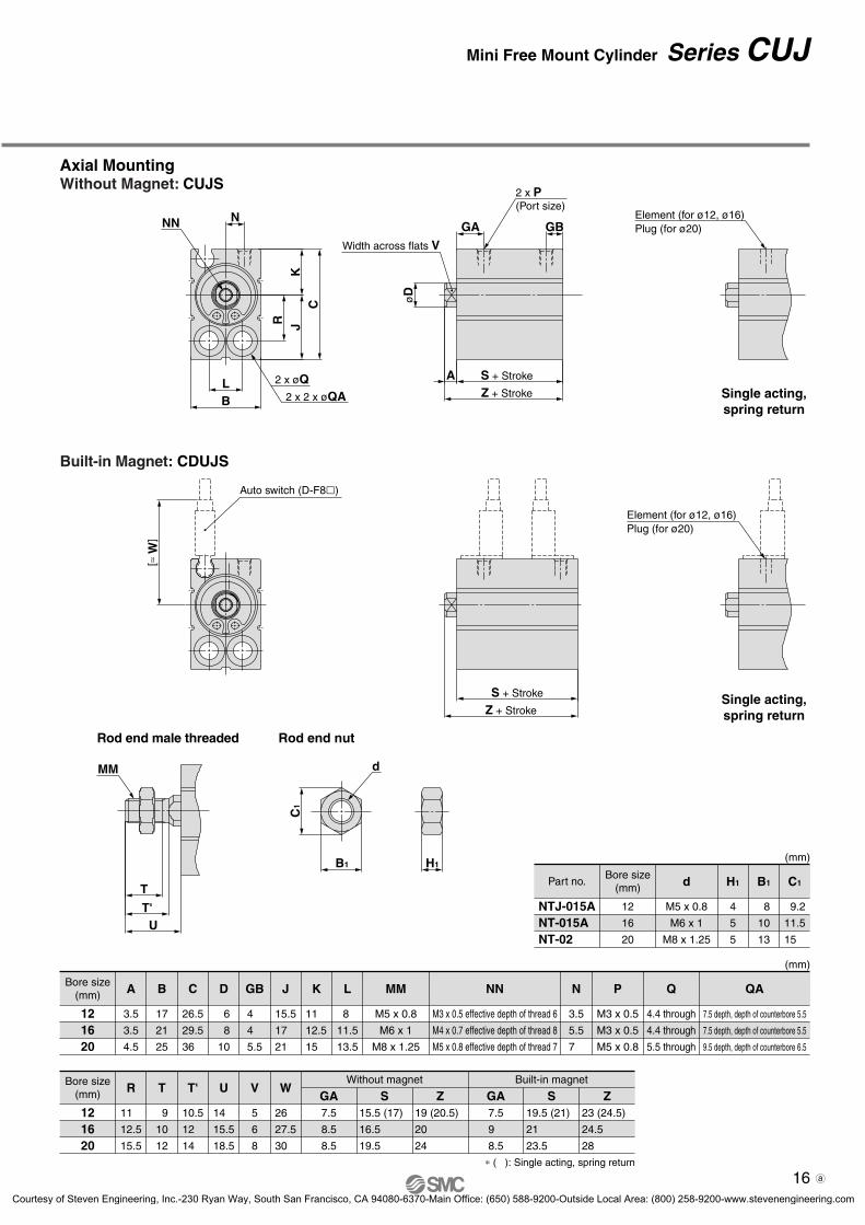
NN
2 x 2 x øQA2 x øQ
KJ
C
B
N
R
L
Z + Stroke
S + Stroke
Auto switch (D-F8)
[≈ W
]
2 x P(Port size)
Z + Stroke
A S + Stroke
GA GB
øD
Width across flats V
Element (for ø12, ø16)Plug (for ø20)
Element (for ø12, ø16)Plug (for ø20)
MM
T
UT'
H1
d
C1
B1
Single acting,spring return
Single acting,spring return
Built-in Magnet: CDUJS
(mm)
NTJ-015ANT-015ANT-02
Part no.
12
16
20
Bore size(mm) d
M5 x 0.8
M6 x 1
M8 x 1.25
H1
4
5
5
B1
8
10
13
C1
9.2
11.5
15
121620
RBore size(mm)
11
12.5
15.5
T
9
10
12
T'
10.5
12
14
U
14
15.5
18.5
V
5
6
8
W
26
27.5
30
S15.5 (17)
16.5
19.5
Z19 (20.5)
20
24
S19.5 (21)
21
23.5
Z23 (24.5)
24.5
28
Without magnet Built-in magnet
(mm)
121620
ABore size(mm)
3.5
3.5
4.5
B
17
21
25
C
26.5
29.5
36
D
6
8
10
N
3.5
5.5
7
J
15.5
17
21
K
11
12.5
15
L
8
11.5
13.5
MM
M5 x 0.8
M6 x 1
M8 x 1.25
P
M3 x 0.5
M3 x 0.5
M5 x 0.8
Q
4.4 through
4.4 through
5.5 through
NN
M3 x 0.5 effective depth of thread 6
M4 x 0.7 effective depth of thread 8
M5 x 0.8 effective depth of thread 7
GB
4
4
5.5
QA
7.5 depth, depth of counterbore 5.5
7.5 depth, depth of counterbore 5.5
9.5 depth, depth of counterbore 6.5
Axial MountingWithout Magnet: CUJS
Rod end male threaded Rod end nut
∗ ( ): Single acting, spring return
GA7.5
8.5
8.5
GA7.5
9
8.5
16
Mini Free Mount Cylinder Series CUJ
Sheet 2.qxd 09.10.20 2:08 PM Page 2
Courtesy of Steven Engineering, Inc.-230 Ryan Way, South San Francisco, CA 94080-6370-Main Office: (650) 588-9200-Outside Local Area: (800) 258-9200-www.stevenengineering.com
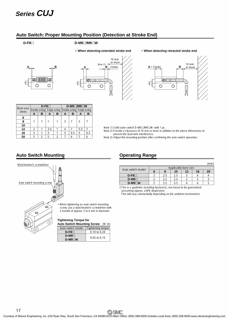
D-F8 D-M9/M9W
• When detecting extended stroke end • When detecting retracted stroke end
10 mmor more
10 mmor more
Auto Switch: Proper Mounting Position (Detection at Stroke End)
Note 2)A B A B – Stroke A + Stroke B
Auto switch mounting screw
Watchmaker’s screwdriver (mm)
D-F8
Auto switch modelApplicable bore size
6223
82.52.53.5
10 12 16 202.52.53.5
324
434
435
D-M9D-M9W
∗ This is a guideline including hysteresis, not meant to be guaranteed. (assuming approx. ±30% dispersion)This will vary substantially depending on the ambient environment.
6810121620
Bore size(mm)
Double acting
1
235
Single acting
1
112
Double acting
3
457
Single actingA B
1
3.53 5
1
112
A B A B
7
7 6.56
3
5.55 7
A B
7
7 6.56
D-F8 D-M9/M9W
Auto Switch Mounting Operating Range
(N·m)Tightening Torque for Auto Switch Mounting Screw
D-F8Auto switch model Tightening torque
0.10 to 0.20
0.05 to 0.15D-M9D-M9W
Note 1) Solid state switch D-M9/M9W: with 1 pc.Note 2) Provide a clearance of 10 mm or more in addition to the above dimensions to
prevent the lead wire interference.Note 3) Adjust the mounting position after confirming the auto switch operation.
• When tightening an auto switch mounting screw, use a watchmaker’s screwdriver with a handle of approx. 5 to 6 mm in diameter.
17
Series CUJ
CUJ-C.qxd 08.5.29 7:24 AM Page 20
Courtesy of Steven Engineering, Inc.-230 Ryan Way, South San Francisco, CA 94080-6370-Main Office: (650) 588-9200-Outside Local Area: (800) 258-9200-www.stevenengineering.com
L
d
Cylinder BCylinder A
Auto switch
Auto switch
Non-magnetic spacer of 2.5 mm or more
CUJ cylinder
Magneticsubstance
18
36
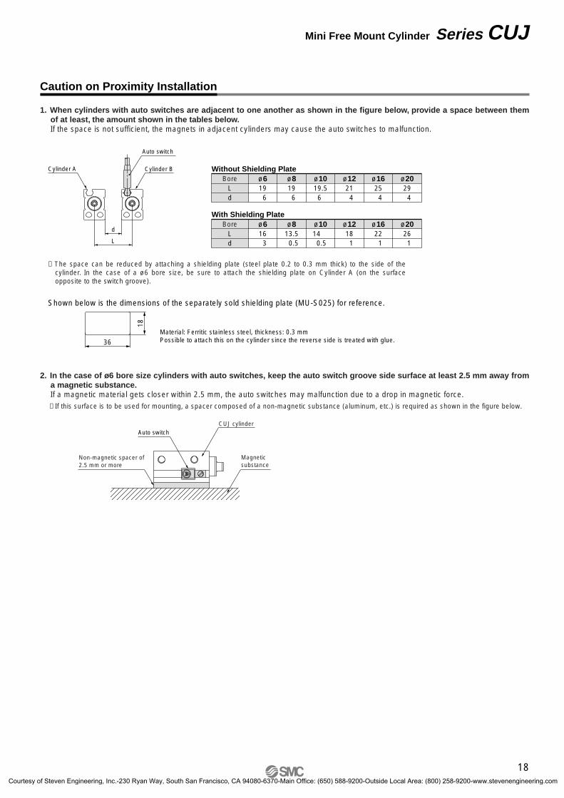
Material: Ferritic stainless steel, thickness: 0.3 mmPossible to attach this on the cylinder since the reverse side is treated with glue.
1. When cylinders with auto switches are adjacent to one another as shown in the figure below, provide a space between them of at least, the amount shown in the tables below.If the space is not sufficient, the magnets in adjacent cylinders may cause the auto switches to malfunction.
∗ The space can be reduced by attaching a shielding plate (steel plate 0.2 to 0.3 mm thick) to the side of the cylinder. In the case of a ø6 bore size, be sure to attach the shielding plate on Cylinder A (on the surface opposite to the switch groove).
2. In the case of ø6 bore size cylinders with auto switches, keep the auto switch groove side surface at least 2.5 mm away from a magnetic substance.If a magnetic material gets closer within 2.5 mm, the auto switches may malfunction due to a drop in magnetic force.∗ If this surface is to be used for mounting, a spacer composed of a non-magnetic substance (aluminum, etc.) is required as shown in the figure below.
Caution on Proximity Installation
Shown below is the dimensions of the separately sold shielding plate (MU-S025) for reference.
Ld
Bore19 6
ø619 6
ø819.56
21 4
25 4
29 4
ø10Without Shielding Plate
ø12 ø16 ø20
Ld
Bore16 3
ø613.5 0.5
ø814 0.5
18 1
22 1
26 1
ø10With Shielding Plate
ø12 ø16 ø20
18
Mini Free Mount Cylinder Series CUJ
CUJ-C.qxd 08.5.29 7:24 AM Page 21
Courtesy of Steven Engineering, Inc.-230 Ryan Way, South San Francisco, CA 94080-6370-Main Office: (650) 588-9200-Outside Local Area: (800) 258-9200-www.stevenengineering.com
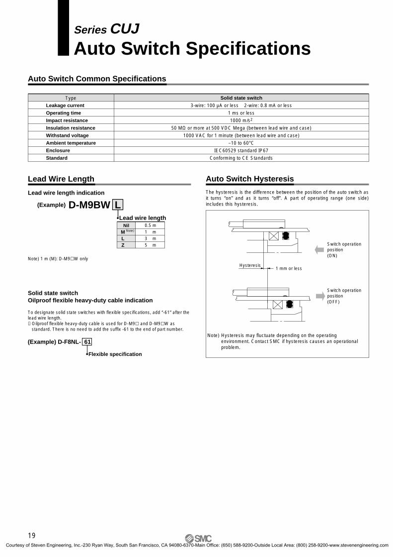
Series CUJAuto Switch Specifications
Type
Leakage current
Operating time
Impact resistance
Insulation resistance
Withstand voltage
Ambient temperature
Enclosure
Standard
Solid state switch
3-wire: 100 µA or less 2-wire: 0.8 mA or less
1 ms or less
1000 m/s2
50 MΩ or more at 500 VDC Mega (between lead wire and case)
1000 VAC for 1 minute (between lead wire and case)
–10 to 60°CIEC60529 standard IP67
Conforming to CE Standards
Lead wire length indication
Solid state switchOilproof flexible heavy-duty cable indication
(Example) LD-M9BW
0.5 m1 mM3 m5 m
LZ
Nil
Lead wire length
Switch operationposition(OFF)
Switch operationposition(ON)
The hysteresis is the difference between the position of the auto switch as it turns “on” and as it turns “off”. A part of operating range (one side) includes this hysteresis.
Note) Hysteresis may fluctuate depending on the operating environment. Contact SMC if hysteresis causes an operational problem.
Flexible specification
(Example) D-F8NL- 61
1 mm or lessHysteresis
To designate solid state switches with flexible specifications, add “-61” after the lead wire length.∗ Oilproof flexible heavy-duty cable is used for D-M9 and D-M9W as
standard. There is no need to add the suffix -61 to the end of part number.
Note) 1 m (M): D-M9W only
Auto Switch Common Specifications
Lead Wire Length Auto Switch Hysteresis
Note)
19
CUJ-C.qxd 08.5.29 7:24 AM Page 22
Courtesy of Steven Engineering, Inc.-230 Ryan Way, South San Francisco, CA 94080-6370-Main Office: (650) 588-9200-Outside Local Area: (800) 258-9200-www.stevenengineering.com
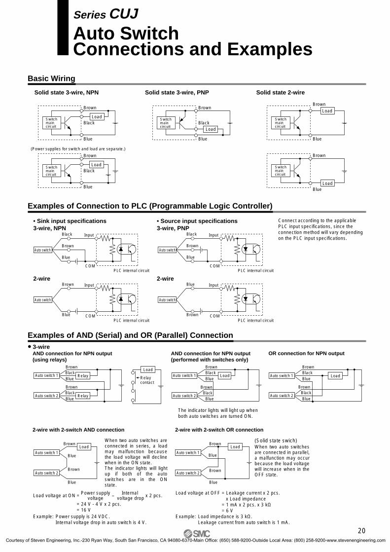
Basic Wiring
Solid state 3-wire, NPN
• Sink input specifications3-wire, NPN
3-wire
Solid state 2-wire
• Source input specifications3-wire, PNP
OR connection for NPN output
2-wire with 2-switch AND connection 2-wire with 2-switch OR connection
2-wire 2-wire
Solid state 3-wire, PNP
Connect according to the applicable PLC input specifications, since the connection method will vary depending on the PLC input specifications.
Power supply Internal Load voltage at ON = voltage – voltage drop x 2 pcs.
= 24 V - 4 V x 2 pcs.= 16 V
Example: Power supply is 24 VDC. Internal voltage drop in auto switch is 4 V.
Load voltage at OFF = Leakage current x 2 pcs. x Load impedance= 1 mA x 2 pcs. x 3 kΩ= 6 V
Example: Load impedance is 3 kΩ.Leakage current from auto switch is 1 mA.
(Power supplies for switch and load are separate.)
Auto switch 1
Auto switch 2
Load
BrownBlackBlue
BrownBlackBlue
Auto switch 1
Brown
Auto switch 2
BlackBlue
Relay
Relay
BrownBlackBlue
Load
Relay contact
Auto switch 1
Auto switch 2
Brown
Blue
Brown
Blue
LoadAuto switch 1
Auto switch 2
Brown
Blue
Brown
Blue
Load
Switch main circuit
Brown
Black
Blue
Load
Brown
Black
Blue
Switch main circuit
Load
Switch main circuit
Brown
Black
Blue
Load
Switch main circuit
Brown
Blue
Load
Brown
Blue
Switch main circuit
Load
Auto switch
InputBlack
COM
Brown
Blue
Auto switch
Input
Blue COM
Brown
Auto switch
InputBlack
PLC internal circuitCOM
Brown
Blue
PLC internal circuit
PLC internal circuit
PLC internal circuit
Auto switch
InputBlue
COMBrown
Examples of AND (Serial) and OR (Parallel) Connection
Examples of Connection to PLC (Programmable Logic Controller)
AND connection for NPN output(using relays)
Auto switch 1
Brown
Auto switch 2
BlackBlue
Load
BrownBlack
Blue
AND connection for NPN output(performed with switches only)
The indicator lights will light up when both auto switches are turned ON.
When two auto switches are connected in series, a load may malfunction because the load voltage will decline when in the ON state.The indicator lights will light up if both of the auto switches are in the ON state.
(Solid state swich)When two auto switches are connected in parallel, a malfunction may occur because the load voltage will increase when in the OFF state.
Series CUJAuto SwitchConnections and Examples
20
CUJ-C.qxd 08.5.29 7:24 AM Page 23
Courtesy of Steven Engineering, Inc.-230 Ryan Way, South San Francisco, CA 94080-6370-Main Office: (650) 588-9200-Outside Local Area: (800) 258-9200-www.stevenengineering.com
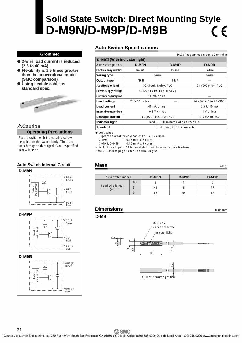
Solid State Switch: Direct Mounting StyleD-M9N/D-M9P/D-M9B
Auto Switch Specifications
Mass
Auto switch model
0.5
3
5
D-M9N
8
41
68
D-M9P
8
41
68
D-M9B
7
38
63
Unit: g
Lead wire length(m)
Grommet PLC: Programmable Logic Controller
Auto switch part no.
Electrical entry direction
Wiring type
Output type
Applicable load
Power supply voltage
Current consumption
Load voltage
Load current
Internal voltage drop
Leakage current
Indicator light
Standard
D-M9N D-M9B
2-wire
—
24 VDC relay, PLC
—
—
24 VDC (10 to 28 VDC)
2.5 to 40 mA
4 V or less
0.8 mA or less
D-M9P
Red LED illuminates when turned ON.
Conforming to CE Standards
3-wire
IC circuit, Relay, PLC
5, 12, 24 VDC (4.5 to 28 V)
10 mA or less
40 mA or less
0.8 V or less
100 µA or less at 24 VDC
In-line In-line In-line
NPN PNP
28 VDC or less —
D-M9 (With indicator light)
Lead wiresOilproof heavy-duty vinyl cable: ø2.7 x 3.2 ellipse D-M9B 0.15 mm2 x 2 coresD-M9N, D-M9P 0.15 mm2 x 3 cores
Note 1) Refer to page 19 for solid state switch common specifications.Note 2) Refer to page 19 for lead wire lengths.
Dimensions
D-M9M2.5 x 4 l Slotted set screw
Indicator light
2.7
22
2.6
4
2.8
3.2
6 Most sensitive position
2-wire load current is reduced (2.5 to 40 mA).
Flexibility is 1.5 times greater than the conventional model (SMC comparison).
Using flexible cable as standard spec.
Operating PrecautionsCaution
Unit: mm
Fix the switch with the existing screw installed on the switch body. The auto switch may be damaged if an unspecified screw is used.
D-M9N
D-M9B
D-M9P
DC (+)Brown
OUTBlack
DC (–)Blue
DC (+)Brown
OUTBlack
DC (–)Blue
OUT (+)Brown
OUT (–)Blue
Auto Switch Internal Circuit
Sw
itch
mai
n ci
rcui
tS
witc
h m
ain
circ
uit
Sw
itch
mai
n ci
rcui
t
21
CUJ-C.qxd 08.5.29 7:24 AM Page 24
Courtesy of Steven Engineering, Inc.-230 Ryan Way, South San Francisco, CA 94080-6370-Main Office: (650) 588-9200-Outside Local Area: (800) 258-9200-www.stevenengineering.com
Auto Switch Specifications
Mass Unit: g
Unit: mmDimensions
Auto switch part no.
0.5
1
3
5
D-M9NW8
14
41
68
D-M9PW8
14
41
68
D-M9BW7
13
38
63
Lead wire length(m)
Grommet PLC: Programmable Logic Controller
Auto switch part no.
Electrical entry direction
Wiring type
Output type
Applicable load
Power supply voltage
Current consumption
Load voltage
Load current
Internal voltage drop
Leakage current
Indicator light
Standard
D-M9NW D-M9BW
2-wire
—
24 VDC relay, PLC
—
—
24 VDC (10 to 28 VDC)
2.5 to 40 mA
4 V or less
0.8 mA or less
D-M9PW
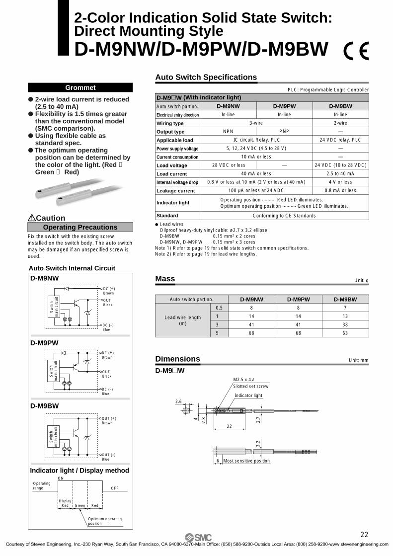
Operating position .......... Red LED illuminates.Optimum operating position .......... Green LED illuminates.
3-wire
IC circuit, Relay, PLC
5, 12, 24 VDC (4.5 to 28 V)
10 mA or less
40 mA or less
0.8 V or less at 10 mA (2 V or less at 40 mA)
100 µA or less at 24 VDC
Conforming to CE Standards
In-line In-line In-line
NPN PNP
28 VDC or less —
D-M9W (With indicator light)
Lead wiresOilproof heavy-duty vinyl cable: ø2.7 x 3.2 ellipse D-M9BW 0.15 mm2 x 2 coresD-M9NW, D-M9PW 0.15 mm2 x 3 cores
Note 1) Refer to page 19 for solid state switch common specifications.Note 2) Refer to page 19 for lead wire lengths.
2-wire load current is reduced (2.5 to 40 mA)
Flexibility is 1.5 times greater than the conventional model (SMC comparison).
Using flexible cable as standard spec.
The optimum operating position can be determined by the color of the light. (Red → Green ← Red)
D-M9NW
D-M9BW
D-M9PW
OUTBlack
DC (+)Brown
DC (–)Blue
DC (+)Brown
OUTBlack
DC (–)Blue
OUT (+)Brown
OUT (–)Blue
Indicator light / Display method
Auto Switch Internal Circuit
ON
OFFOperatingrange
Optimum operatingposition
DisplayRed Green Red
D-M9W
2-Color Indication Solid State Switch: Direct Mounting StyleD-M9NW/D-M9PW/D-M9BW
M2.5 x 4 l
Indicator light
2.7
22
2.6
4
2.8
3.2
6 Most sensitive position
Operating PrecautionsCaution
Fix the switch with the existing screw installed on the switch body. The auto switch may be damaged if an unspecified screw is used.
Slotted set screw
Sw
itch
mai
n ci
rcui
tS
witc
h m
ain
circ
uit
Sw
itch
mai
n ci
rcui
t
22
CUJ-C.qxd 08.5.29 7:24 AM Page 25
Courtesy of Steven Engineering, Inc.-230 Ryan Way, South San Francisco, CA 94080-6370-Main Office: (650) 588-9200-Outside Local Area: (800) 258-9200-www.stevenengineering.com
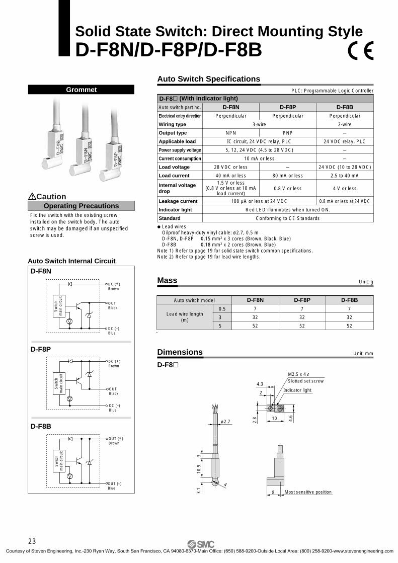
D-F8 (With indicator light)Grommet
D-F8N
D-F8B
D-F8P
Auto Switch Specifications
Dimensions
Auto switch part no.
Electrical entry direction
Wiring type
Output type
Applicable load
Power supply voltage
Current consumption
Load voltage
Load current
Leakage current
Indicator light
Standard
D-F8N
Perpendicular
NPN
28 VDC or less
40 mA or less
D-F8B
Perpendicular
2-wire
–
24 VDC relay, PLC
–
–
24 VDC (10 to 28 VDC)
2.5 to 40 mA
4 V or less
0.8 mA or less at 24 VDC
D-F8P
Perpendicular
PNP
–
80 mA or less
0.8 V or less
Lead wiresOilproof heavy-duty vinyl cable: ø2.7, 0.5 mD-F8N, D-F8P 0.15 mm2 x 3 cores (Brown, Black, Blue)D-F8B 0.18 mm2 x 2 cores (Brown, Blue)
Note 1) Refer to page 19 for solid state switch common specifications.Note 2) Refer to page 19 for lead wire lengths.
D-F8
1.5 V or less(0.8 V or less at 10 mA
load current)
Red LED illuminates when turned ON.
Conforming to CE Standards
100 µA or less at 24 VDC
OUTBlack
DC (+)Brown
DC (–)Blue
DC (+)Brown
DC (–)Blue
OUTBlack
OUT (+)Brown
OUT (–)Blue
PLC: Programmable Logic Controller
3-wire
IC circuit, 24 VDC relay, PLC
5, 12, 24 VDC (4.5 to 28 VDC)
10 mA or less
M2.5 x 4 l
Slotted set screw
Indicator light
Most sensitive position
10 4.6
2.8
2
4.3
ø2.7
4
3.1
10.9
3
8
Auto Switch Internal Circuit
Mass
Auto switch model
0.5
3
5
D-F8N
7
32
52
D-F8P
7
32
52
D-F8B
7
32
52
Fix the switch with the existing screw installed on the switch body. The auto switch may be damaged if an unspecified screw is used.
Operating PrecautionsCaution
Unit: g
Unit: mm
Lead wire length(m)
Solid State Switch: Direct Mounting StyleD-F8N/D-F8P/D-F8B
Internal voltage drop
Sw
itch
mai
n ci
rcui
tS
witc
hm
ain
circ
uit
Sw
itch
mai
n ci
rcui
t
23
CUJ-C.qxd 08.5.29 7:24 AM Page 26
Courtesy of Steven Engineering, Inc.-230 Ryan Way, South San Francisco, CA 94080-6370-Main Office: (650) 588-9200-Outside Local Area: (800) 258-9200-www.stevenengineering.com
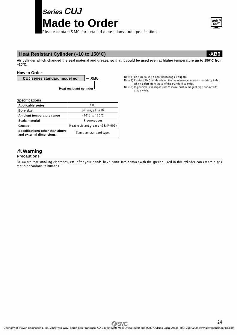
Series CUJMade to OrderPlease contact SMC for detailed dimensions and specifications.
Heat Resistant Cylinder (–10 to 150°C) -XB6Air cylinder which changed the seal material and grease, so that it could be used even at higher temperature up to 150°C from –10°C.
XB6
Heat resistant cylinder
CUJ series standard model no.
How to Order
SpecificationsApplicable series
Bore size
Ambient temperature range
Seals material
Grease
Specifications other than above and external dimensions
CUJ
ø4, ø6, ø8, ø10
–10°C to 150°CFluororubber
Heat resistant grease (GR-F-005)
Same as standard type.
PrecautionsWarning
Be aware that smoking cigarettes, etc. after your hands have come into contact with the grease used in this cylinder can create a gas that is hazardous to humans.
Note 1) Be sure to use a non-lubricating air supply.Note 2) Contact SMC for details on the maintenance intervals for this cylinder,
which differs from those of the standard cylinder.Note 3) In principle, it is impossible to make built-in magnet type and/or with
auto switch.
24
CUJ-C.qxd 08.5.29 7:24 AM Page 27
Courtesy of Steven Engineering, Inc.-230 Ryan Way, South San Francisco, CA 94080-6370-Main Office: (650) 588-9200-Outside Local Area: (800) 258-9200-www.stevenengineering.com
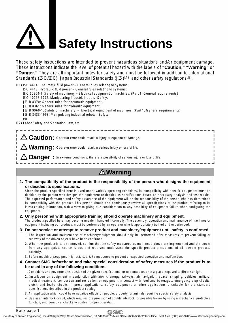
Safety InstructionsThese safety instructions are intended to prevent hazardous situations and/or equipment damage. These instructions indicate the level of potential hazard with the labels of “Caution,” “Warning” or “Danger.” They are all important notes for safety and must be followed in addition to International Standards (ISO/IEC), Japan Industrial Standards (JIS)∗1) and other safety regulations∗2).∗ 1) ISO 4414: Pneumatic fluid power – General rules relating to systems.
ISO 4413: Hydraulic fluid power – General rules relating to systems.IEC 60204-1: Safety of machinery – Electrical equipment of machines. (Part 1: General requirements)ISO 10218-1992: Manipulating industrial robots -Safety.JIS B 8370: General rules for pneumatic equipment.JIS B 8361: General rules for hydraulic equipment. JIS B 9960-1: Safety of machinery – Electrical equipment of machines. (Part 1: General requirements)JIS B 8433-1993: Manipulating industrial robots - Safety. etc.
∗ 2) Labor Safety and Sanitation Law, etc.
1. The compatibility of the product is the responsibility of the person who designs the equipment or decides its specifications. Since the product specified here is used under various operating conditions, its compatibility with specific equipment must be decided by the person who designs the equipment or decides its specifications based on necessary analysis and test results. The expected performance and safety assurance of the equipment will be the responsibility of the person who has determined its compatibility with the product. This person should also continuously review all specifications of the product referring to its latest catalog information, with a view to giving due consideration to any possibility of equipment failure when configuring the equipment.
2. Only personnel with appropriate training should operate machinery and equipment.The product specified here may become unsafe if handled incorrectly. The assembly, operation and maintenance of machines or equipment including our products must be performed by an operator who is appropriately trained and experienced.
3. Do not service or attempt to remove product and machinery/equipment until safety is confirmed.1. The inspection and maintenance of machinery/equipment should only be performed after measures to prevent falling or
runaway of the driven objects have been confirmed.
2. When the product is to be removed, confirm that the safety measures as mentioned above are implemented and the power from any appropriate source is cut, and read and understand the specific product precautions of all relevant products carefully.
3. Before machinery/equipment is restarted, take measures to prevent unexpected operation and malfunction.
4. Contact SMC beforehand and take special consideration of safety measures if the product is to be used in any of the following conditions. 1. Conditions and environments outside of the given specifications, or use outdoors or in a place exposed to direct sunlight.
2. Installation on equipment in conjunction with atomic energy, railways, air navigation, space, shipping, vehicles, military, medical treatment, combustion and recreation, or equipment in contact with food and beverages, emergency stop circuits, clutch and brake circuits in press applications, safety equipment or other applications unsuitable for the standard specifications described in the product catalog.
3. An application which could have negative effects on people, property, or animals requiring special safety analysis.
4. Use in an interlock circuit, which requires the provision of double interlock for possible failure by using a mechanical protective function, and periodical checks to confirm proper operation.
Warning
Caution: Operator error could result in injury or equipment damage.
Danger : In extreme conditions, there is a possibility of serious injury or loss of life.
Warning: Operator error could result in serious injury or loss of life.
Back page 1
CUJ-C.qxd 08.5.29 7:24 AM Page 28
Courtesy of Steven Engineering, Inc.-230 Ryan Way, South San Francisco, CA 94080-6370-Main Office: (650) 588-9200-Outside Local Area: (800) 258-9200-www.stevenengineering.com
Safety Instructions
Limited Warranty and Disclaimer/Compliance Requirements The product used is subject to the following “Limited Warranty and Disclaimer” and “Compliance Requirements”. Read and accept them before using the product.
The product is provided for use in manufacturing industries.The product herein described is basically provided for peaceful use in manufacturing industries. If considering using the product in other industries, consult SMC beforehand and exchange specifications or a contract if necessary. If anything is unclear, contact your nearest sales branch.
Caution
Limited Warranty and Disclaimer
1. The warranty period of the product is 1 year in service or 1.5 years after the product is deliv-ered.∗3)
Also, the product may have specified durability, running distance or replacement parts. Please consult your nearest sales branch.
2. For any failure or damage reported within the warranty period which is clearly our responsibility, a replacement product or necessary parts will be provided. This limited warranty applies only to our product independently, and not to any other damage incurred due to the failure of the product.
3. Prior to using SMC products, please read and understand the warranty terms and disclaimers noted in the specified catalog for the particular products.∗ 3) Vacuum pads are excluded from this 1 year warranty.
A vacuum pad is a consumable part, so it is warranted for a year after it is delivered. Also, even within the warranty period, the wear of a product due to the use of the vacuum pad or failure due to the deterioration of rubber material are not covered by the limited warranty.
Compliance RequirementsWhen the product is exported, strictly follow the laws required by the Ministry of Economy, Trade and Industry (Foreign Exchange and Foreign Trade Control Law).
Back page 2
CUJ-C.qxd 08.5.29 7:24 AM Page 29
Courtesy of Steven Engineering, Inc.-230 Ryan Way, South San Francisco, CA 94080-6370-Main Office: (650) 588-9200-Outside Local Area: (800) 258-9200-www.stevenengineering.com
Design and Selection
Auto SwitchesPrecautions 1Be sure to read this before handling.
Warning1. Check the specifications.
Read the specifications carefully and use this product appro-priately. The product may be damaged or malfunction if it is used outside the specification range of load current, voltage, temperature or impact.SMC will not, under any circumstances, assume responsibili-ty for damage incurred when used outside the specification range.
2. Cautions for use in an interlock circuitWhen an auto switch is used for an interlock signal requiring high reliability, devise a double interlock system to avoid trou-ble by providing a mechanical protection function, or by also using another switch (sensor) together with the auto switch.Also, perform periodic maintenance inspections and confirm proper operation.
3. Do not disassemble the product or make any modifications, including additional ma-chining.It may cause human injury and/or an accident.
Caution1. Use caution regarding the length of time
that an auto switch is ON at an intermediate stroke position.When an auto switch is placed at an intermediate position of the stroke and a load is driven at the time the piston passes, the auto switch will operate, but if the speed is too great, the operating time will be shortened and the load may not oper-ate properly. The maximum detectable piston speed is:
Caution2. Wiring should be kept as short as possible.
Although the wire length should not affect the function of the switch, use a wire length of 100 m or less.Even when the length is 100 m or less, the longer the wire is, the greater the possibility of influence from external noise.To deal with noise when the wire length is long, we recom-mend installation of a ferrite core at either end of the lead wire.Due to the nature of their construction, contact protection boxes are not required for solid state auto switches.
3. Do not use a load that generates surge vol-tage. If a surge voltage is generated, the discharge occurs at the contact, possibly resulting in the shortening of product life.When a load such as a relay which generates surge is driven, use a switch with a built-in surge absorbing element.
4. Use caution when multiple cylinders/actua-tors are used close to each other.When two or more cylinders/actuators with auto switches are lined up in close proximity to each other, magnetic field inter-ference may cause the switches to malfunction. Maintain a minimum cylinder/actuator separation of 40 mm. (When an allowable interval is specified for each cylinder and actuator series, use the indicated value.)By using a magnetic shielding plate (MU-S025) or commer-cially available magnetic shielding tape, it may be possible to reduce the interference caused by magnetism.
5. Mount a switch at the center of the operat-ing range.Adjust the mounting position of an auto switch so that the pis-ton stops at the center of the operating range (the range in which a switch is ON). (The mounting positions shown in the catalog indicate the optimum position at the stroke end.) If mounted at the end of the operating range (around the bor-derline of ON and OFF), the operation will be unstable, and the life of reed switches may be shortened.
V (mm/s) = x 1000
Auto switch operating range (mm)
Load operatingtime (ms)
Back page 3
CUJ-C.qxd 08.5.29 7:24 AM Page 30
Courtesy of Steven Engineering, Inc.-230 Ryan Way, South San Francisco, CA 94080-6370-Main Office: (650) 588-9200-Outside Local Area: (800) 258-9200-www.stevenengineering.com
Design and Selection
10. Limitations on possible detection positionsDepending on the mounting hardware of the cylinder/actua-tor, physical interference may make it impossible to mount the auto switch in some positions or on some surfaces (lower surface of foot bracket, etc.)For the auto switch mounting position, check carefully to en-sure there is no interference with the cylinder/actuator mount-ing bracket (trunnion, reinforcing ring etc.).
11. Use the proper combinations.The auto switch is adjusted so as to operate properly when used with SMC cylinders/actuators.Take note that improper mounting, mechanical changes in mounting conditions, and use of cylinders/actuators not made by SMC may result in malfunction.
Mounting and Adjustment
Caution1. Do not drop or bump.
Do not drop, bump, or apply excessive impacts (1000 m/s2 or more while handling. Although the body of the auto switch may not be damaged, the inside of the auto switch could be damaged and cause a malfunction.
2. Mount auto switches using the proper tight-ening torque.When a switch is tightened beyond the fastening torque range, the mounting screws, auto switch mounting brackets or auto switch may be damaged.On the other hand, tightening below the fastening torque range may allow the auto switch to slip out of position.
3. Do not carry a cylinder/actuator by the auto switch lead wires.Never carry a cylinder/actuator by its lead wires. This may not only cause broken lead wires, but it may cause internal ele-ments of the auto switch to be damaged by the stress.
4. Do not mount the auto switch to the main body with anything other than the included set screw. Using screws other than those indicated may cause damage to the auto switch.
Caution6. Use caution regarding the internal voltage
drop of a switch.• If auto switches are connected in series as shown below,
take note that there will be a large voltage drop because of internal resistance in the light-emitting diodes. (Refer to in-ternal voltage drop in the auto switch specifications.)[The voltage drop will be “n” times larger when “n” auto switches are connected.]Even though an auto switch operates normally, the load may not operate.
• Similarly, when operating below a specified voltage, it is possible that the load may be ineffective even though the auto switch function is normal. Therefore, the formula below should be satisfied after confirming the minimum operating voltage of the load.
<2-wire>Generally, the internal voltage drop will be greater, so use caution. Also, note that a 12 VDC relay is not applicable.
7. Use caution regarding the leakage current.<2-wire>With a 2-wire auto switch, current (leakage current) flows to the load to operate the internal circuit even when in the OFF state.
If the condition given in the above formula is not met, it will not reset correctly (stays ON). Use a 3-wire switch if this specification cannot be satisfied.Moreover, leakage current flow to the load will be “n” times larger when “n” auto switches are connected in parallel.
8. Ensure sufficient space for maintenance ac-tivities.When designing an application, be sure to allow sufficient space for maintenance and inspection.
9. Use caution when mounting multiple units.When the number of auto switches mounted is “n”, this repre-sents the number of auto switches that can physically be mounted with the cylinder/actuator.As the detection interval in this situation is determined by the mounting construction of the auto switch and the housing di-mensions, it may not always be possible to mount the switches at the desired interval and/or setting position.
Load
Supplyvoltage
Internal voltagedrop of auto switch
Minimum operating voltage of load
– >
Current to operate load (OFF condition) Leakage current>
Auto SwitchesPrecautions 2Be sure to read this before handling.
Back page 4
CUJ-C.qxd 08.5.29 7:24 AM Page 31
Courtesy of Steven Engineering, Inc.-230 Ryan Way, South San Francisco, CA 94080-6370-Main Office: (650) 588-9200-Outside Local Area: (800) 258-9200-www.stevenengineering.com
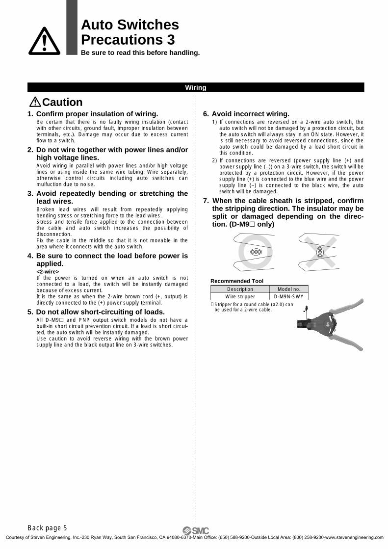
6. Avoid incorrect wiring.1) If connections are reversed on a 2-wire auto switch, the
auto switch will not be damaged by a protection circuit, but the auto switch will always stay in an ON state. However, it is still necessary to avoid reversed connections, since the auto switch could be damaged by a load short circuit in this condition.
2) If connections are reversed (power supply line (+) and power supply line (–)) on a 3-wire switch, the switch will be protected by a protection circuit. However, if the power supply line (+) is connected to the blue wire and the power supply line (–) is connected to the black wire, the auto switch will be damaged.
7. When the cable sheath is stripped, confirm the stripping direction. The insulator may be split or damaged depending on the direc-tion. (D-M9 only)
Recommended ToolDescription
Wire stripperModel no.
D-M9N-SWY
∗ Stripper for a round cable (ø2.0) can be used for a 2-wire cable.
Wiring
Caution1. Confirm proper insulation of wiring.
Be certain that there is no faulty wiring insulation (contact with other circuits, ground fault, improper insulation between terminals, etc.). Damage may occur due to excess current flow to a switch.
2. Do not wire together with power lines and/or high voltage lines. Avoid wiring in parallel with power lines and/or high voltage lines or using inside the same wire tubing. Wire separately, otherwise control circuits including auto switches can mulfuction due to noise.
3. Avoid repeatedly bending or stretching the lead wires.Broken lead wires will result from repeatedly applying bending stress or stretching force to the lead wires.Stress and tensile force applied to the connection between the cable and auto switch increases the possibility of disconnection.Fix the cable in the middle so that it is not movable in the area where it connects with the auto switch.
4. Be sure to connect the load before power is applied.<2-wire>If the power is turned on when an auto switch is not connected to a load, the switch will be instantly damaged because of excess current.It is the same as when the 2-wire brown cord (+, output) is directly connected to the (+) power supply terminal.
5. Do not allow short-circuiting of loads.All D-M9 and PNP output switch models do not have a built-in short circuit prevention circuit. If a load is short circui-ted, the auto switch will be instantly damaged.Use caution to avoid reverse wiring with the brown power supply line and the black output line on 3-wire switches.
Auto SwitchesPrecautions 3Be sure to read this before handling.
Back page 5
CUJ-C.qxd 08.5.29 7:24 AM Page 32
Courtesy of Steven Engineering, Inc.-230 Ryan Way, South San Francisco, CA 94080-6370-Main Office: (650) 588-9200-Outside Local Area: (800) 258-9200-www.stevenengineering.com
Maintenance
Warning1. Removal of equipment, and supply/exhaust
of compressed airBefore any machinery or equipment is removed, first ensure that the appropriate measures are in place to prevent the fall or erratic movement of driven objects and equipment, then cut off the electric power and reduce the pressure in the sys-tem to zero. Only then should you proceed with the removal of any machinery and equipment.When machinery is restarted, proceed with caution after con-firming that appropriate measures are in place to prevent cy-linders/actuators from sudden movement.
Caution1. Perform the following maintenance periodi-
cally in order to prevent possible danger due to unexpected auto switch malfunction.1) Securely tighten switch mounting screws.
If screws become loose or the mounting position is disloca-ted, retighten screws securely after readjusting the mount-ing position.
2) Confirm that there is no damage to lead wires.To prevent faulty insulation, replace switches or repair lead wires if damage is discovered.
3) Checking the green light-up of 2-color indication auto switchesConfirm that the green LED light turns on and operation stops where it is set. If the red LED light turns on and oper-ation stops, the mounting position is incorrect. Re-install in a new position so that the green LED lights up.
Caution6. Avoid accumulation of iron debris or close
contact with magnetic substances.When a large amount of ferrous debris such as machining chips or spatter is accumulated, or a magnetic substance (something attracted by a magnet) is brought into close prox-imity to the cylinder/actuator with an auto switch, it may cause the auto switches to malfunction due to a loss of the magnetic force inside the cylinder.
7. Consult with SMC concerning water resis-tance, elasticity of lead wires, and use at welding sites.
8. Do not use in direct sunlight.9. Do not mount the product in locations
where it is exposed to radiant heat.
Operating Environment
Warning1. Never use in the presence of explosive
gases. The construction of our auto switches does not make them explosion-proof. Never use them in the presence of an explo-sive gas, as this may cause a serious explosion.Consult SMC for ATEX directive products.
Caution1. Do not use in an area where a magnetic field
is generated.Auto switches will malfunction or magnets inside cylinders/ac-tuators will become demagnetized.
2. Do not use in environments where the auto switches are under water or constantly ex-posed to water.Although switches satisfy the IEC standard IP67 structure, do not use switches in applications where it will be continually exposed to water splash or spray. Poor insulation or swelling of the potting resin inside the switches may cause a malfunc-tion.
3. Do not use in environments with oil or chemicals.Consult with SMC if auto switches will be used in an environ-ment with coolants, cleaning solvents, various oils or chemi-cals. If auto switches are used under these conditions for even a short period of time, they may be adversely affected by improper insulation, a malfunction due to swelling of the potting resin, or hardening of the lead wires.
4. Do not use in an environment with tempera-ture cycles.Consult with SMC if switches are to be used where there are temperature cycles other than normal temperature changes, as they may be adversely affected internally.
5. Do not use in locations where surges are generated.When there are units (solenoid type lifters, high frequency in-duction furnaces, motors, radio equipment, etc.) which gener-ate a large amount of surge or electromagnetic waves in the area around cylinders/actuators with solid state auto switches, this may cause deterioration or damage to the switches. Avoid sources of surge generation and crossed lines.
Auto SwitchesPrecautions 4Be sure to read this before handling.
Back page 6
CUJ-C.qxd 08.5.29 7:24 AM Page 33
Courtesy of Steven Engineering, Inc.-230 Ryan Way, South San Francisco, CA 94080-6370-Main Office: (650) 588-9200-Outside Local Area: (800) 258-9200-www.stevenengineering.com
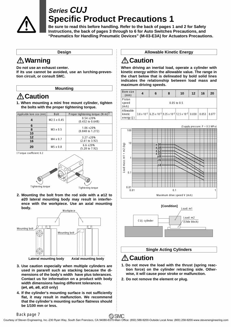
Mounting
Design
WarningDo not use an exhaust center. If its use cannot be avoided, use an lurching-preven-tion circuit, or consult SMC.
Allowable Kinetic Energy
Caution
Tightening torque Tightening torque
CautionWhen driving an inertial load, operate a cylinder with kinetic energy within the allowable value. The range in the chart below that is delineated by bold solid lines indicates the relationship between load mass and maximum driving speeds.
Single Acting Cylinders
Caution
1. When mounting a mini free mount cylinder, tighten the bolts with the proper tightening torque.
3. Use caution especially when multiple cylinders are used in pararell such as stacking because the di-mensions of the body’s width have plus tolerances.Contact us for information on a product with body width dimensions having different tolerances. (ø4, ø6, ø8, ø10 only)
4. If the cylinder’s mounting surface is not sufficiently flat, it may result in malfunction. We recommend that the cylinder’s mounting surface flatness should be 1/100 mm or less.
2. Mounting the bolt from the rod side with a ø12 to ø20 lateral mounting body may result in interfer-ence with the workpiece. Use an axial mounting body.
4 6 8 10 12 16 20
3.8 x 10⁻³ 6.25 x 10⁻³ 9.35 x 10⁻³ 12.5 x 10⁻³ 0.030 0.053 0.077
Bore size(mm)
0.05 to 0.5Piston speed (m/s)
Allowable kinetic energy (J)
[Condition]Load: m1
Load: m2
(Slide block)CUJ cylinder
Workpiece
Mounting bolt
Lateral mounting body Axial mounting body
Mounting bolt
4
68101216
20
M2.5 x 0.45
M3 x 0.5
M4 x 0.7
M5 x 0.8
0.54 ±20%(0.432 to 0.648)
1.06 ±20%(0.848 to 1.272)
3.27 ±20%(2.61 to 3.92)
6.6 ±20%(5.28 to 7.92)
Applicable bore size (mm) Bolt Proper tightening torque (N·m)∗
∗ Torque coefficient: 0.2
0.01
0.1
1
10
100
0.01 0.1 1
Maximum drive speed V (m/s)
Load
mas
s m
1 +
m2
(kg) ø20
ø16ø12ø10ø8ø6
ø4
(Supply pressure: P = 0.5 MPa)
1. Do not move the load with the thrust (spring reac-tion force) on the cylinder retracting side. Other-wise, it will cause poor stroke or malfunction.
2. Do not remove the element or plug.
Series CUJSpecific Product Precautions 1Be sure to read this before handling. Refer to the back of pages 1 and 2 for Safety Instructions, the back of pages 3 through to 6 for Auto Switches Precautions, and “Pneumatics for Handling Pneumatic Devices” (M-03-E3A) for Actuators Precautions.
Back page 7
CUJ-C.qxd 08.5.29 7:24 AM Page 34
Courtesy of Steven Engineering, Inc.-230 Ryan Way, South San Francisco, CA 94080-6370-Main Office: (650) 588-9200-Outside Local Area: (800) 258-9200-www.stevenengineering.com
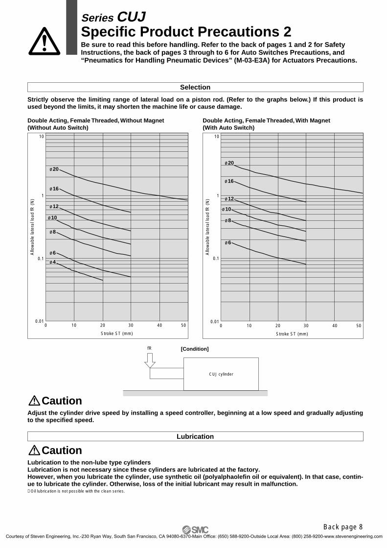
Lubrication
CautionLubrication to the non-lube type cylindersLubrication is not necessary since these cylinders are lubricated at the factory.However, when you lubricate the cylinder, use synthetic oil (polyalphaolefin oil or equivalent). In that case, contin-ue to lubricate the cylinder. Otherwise, loss of the initial lubricant may result in malfunction.∗ Oil lubrication is not possible with the clean series.
CautionAdjust the cylinder drive speed by installing a speed controller, beginning at a low speed and gradually adjusting to the specified speed.
Selection
Strictly observe the limiting range of lateral load on a piston rod. (Refer to the graphs below.) If this product is used beyond the limits, it may shorten the machine life or cause damage.
[Condition]fR
CUJ cylinder
0.01
0.1
1
10
0 10 20 30 40 50
Allo
wab
le la
tera
l loa
d fR
(N
)
Stroke ST (mm)
Double Acting, Female Threaded, Without Magnet(Without Auto Switch)
0.01
0.1
1
10
0 10 20 30 40 50
Allo
wab
le la
tera
l loa
d fR
(N
)
Stroke ST (mm)
Double Acting, Female Threaded, With Magnet(With Auto Switch)
ø20
ø16
ø12
ø10
ø8
ø6
ø20
ø16
ø12
ø10
ø8
ø6
ø4
Series CUJSpecific Product Precautions 2Be sure to read this before handling. Refer to the back of pages 1 and 2 for Safety Instructions, the back of pages 3 through to 6 for Auto Switches Precautions, and “Pneumatics for Handling Pneumatic Devices” (M-03-E3A) for Actuators Precautions.
Back page 8
CUJ-C.qxd 08.5.29 7:24 AM Page 35
Courtesy of Steven Engineering, Inc.-230 Ryan Way, South San Francisco, CA 94080-6370-Main Office: (650) 588-9200-Outside Local Area: (800) 258-9200-www.stevenengineering.com
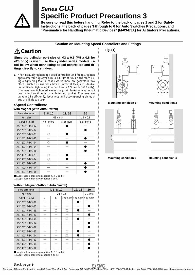
Caution on Mounting Speed Controllers and Fittings
Caution
Mounting condition 1
Mounting condition 4
Fig. (1)
Mounting condition 3
Since the cylinder port size of M3 x 0.5 (M5 x 0.8 for ø20 only) is used, use the cylinder series models lis-ted below when connecting speed controllers and fit-tings directly to cylinders.
Mounting condition 2<Speed Controllers>With Magnet (With Auto Switch)
Bore size (mm)
Port size
Stroke (mm)
AS121F-M3-02
AS121F-M5-02
AS121F-M3-23
AS121F-M5-23
AS121F-M3-04
AS121F-M5-04
AS121F-M5-06
AS131F-M3-23
AS131F-M3-04
AS131F-M5-23
AS131F-M5-04
AS131F-M5-06
: Applicable to mounting condition 1, 2, 3 and 4.: Applicable to mounting condition 1 and 3.
Without Magnet (Without Auto Switch)
Bore size (mm)
Port size
Stroke (mm)
AS121F-M3-02
AS121F-M5-02
AS121F-M3-23
AS121F-M5-23
AS121F-M3-04
AS121F-M5-04
AS121F-M5-06
AS131F-M3-23
AS131F-M3-04
AS131F-M5-23
AS131F-M5-04
AS131F-M5-06
4, 6, 8, 10 12, 16 20M3 x 0.5 M5 x 0.8
4 6 8 or more 5 or more 5 or more
6, 8, 10M3 x 0.5
4 or more
12, 16
5 or more
20M5 x 0.8
5 or more
: Applicable to mounting condition 1, 2, 3 and 4.: Applicable to mounting condition 1 and 3.
1. After manually tightening speed controllers and fittings, tighten approximately a quarter turn (a 1/6 turn for ø20 only) more us-ing a tightening tool. In cases where there are gaskets in two places such as universal elbows, universal tees, etc., double the additional tightening to a half turn (a 1/3 turn for ø20 only). If screws are tightened excessively, air leakage may result due to broken threads or a deformed gasket. If screws are tightened insufficiently, looseness and accompanying air leak-age are likely to occur.
Series CUJSpecific Product Precautions 3Be sure to read this before handling. Refer to the back of pages 1 and 2 for Safety Instructions, the back of pages 3 through to 6 for Auto Switches Precautions, and “Pneumatics for Handling Pneumatic Devices” (M-03-E3A) for Actuators Precautions.
Back page 9
CUJ-C.qxd 08.5.29 7:24 AM Page 36
Courtesy of Steven Engineering, Inc.-230 Ryan Way, South San Francisco, CA 94080-6370-Main Office: (650) 588-9200-Outside Local Area: (800) 258-9200-www.stevenengineering.com
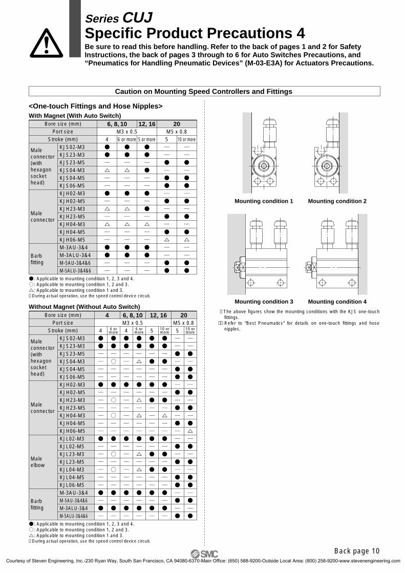
Bore size (mm)Port size
Stroke (mm)
Maleconnector(with hexagonsocket head)
Maleconnector
Maleelbow
Barb fitting
4 6, 8, 10 12, 16 20M3 x 0.5 M5 x 0.8
4 6 ormore 4 6 or
more 5 10 ormore 5 10 or
more
KJS02-M3KJS23-M3KJS23-M5KJS04-M3KJS04-M5KJS06-M5KJH02-M3KJH02-M5KJH23-M3KJH23-M5KJH04-M3KJH04-M5KJH06-M5KJL02-M3KJL02-M5KJL23-M3KJL23-M5KJL04-M3KJL04-M5KJL06-M5M-3AU-3&4M-5AU-3&4&6M-3ALU-3&4M-5ALU-3&4&6
Caution on Mounting Speed Controllers and Fittings
<One-touch Fittings and Hose Nipples>
Mounting condition 1 Mounting condition 2
Mounting condition 3 Mounting condition 4
With Magnet (With Auto Switch)Bore size (mm)
Port sizeStroke (mm)
Maleconnector(with hexagonsocket head)
Maleconnector
Barb fitting
6, 8, 10 12, 16 20M5 x 0.8M3 x 0.5
4 6 or more 5 10 or more5 or moreKJS02-M3KJS23-M3KJS23-M5KJS04-M3KJS04-M5KJS06-M5KJH02-M3KJH02-M5KJH23-M3KJH23-M5KJH04-M3KJH04-M5KJH06-M5M-3AU-3&4M-3ALU-3&4M-5AU-3&4&6M-5ALU-3&4&6
∗ During actual operation, use the speed control device circuit.
∗ During actual operation, use the speed control device circuit.
: Applicable to mounting condition 1, 2, 3 and 4.: Applicable to mounting condition 1, 2 and 3.: Applicable to mounting condition 1 and 3.
: Applicable to mounting condition 1, 2, 3 and 4.: Applicable to mounting condition 1, 2 and 3.: Applicable to mounting condition 1 and 3.
Without Magnet (Without Auto Switch)
Series CUJSpecific Product Precautions 4Be sure to read this before handling. Refer to the back of pages 1 and 2 for Safety Instructions, the back of pages 3 through to 6 for Auto Switches Precautions, and “Pneumatics for Handling Pneumatic Devices” (M-03-E3A) for Actuators Precautions.
∗ The above figures show the mounting conditions with the KJS one-touch fittings.
∗∗ Refer to “Best Pneumatics” for details on one-touch fittings and hose nipples.
Back page 10
CUJ-C.qxd 08.5.29 7:24 AM Page 37
Courtesy of Steven Engineering, Inc.-230 Ryan Way, South San Francisco, CA 94080-6370-Main Office: (650) 588-9200-Outside Local Area: (800) 258-9200-www.stevenengineering.com
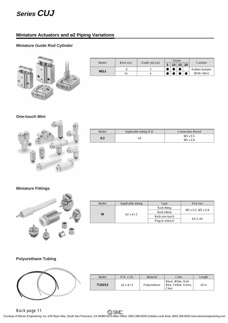
Miniature Actuators and ø2 Piping Variations
Model Bore size
6
10MGJ
Guide rod size
5
6
Stroke
5 10Cushion
Rubber bumper(Both sides)
15 20
Model Applicable tubing
ø2 x ø1.2M
Type
Barb fitting
Barb elbow
Barb one-touch
Plug-in reducer
Port size
M3 x 0.5, M5 x 0.8
ø3.2, ø4
Model O.D. x I.D. Material Color
Black, White, Red, Blue, Yellow, Green,Clear
Length
ø2 x ø1.2 PolyurethaneTU0212 20 m
Miniature Guide Rod Cylinder
Miniature Fittings
Polyurethane Tubing
Model Applicable tubing O.D.
ø2M3 x 0.5M5 x 0.8
KJ
Connection thread
One-touch Mini
Back page 11
Series CUJ
CUJ-C.qxd 08.5.29 7:24 AM Page 38
Courtesy of Steven Engineering, Inc.-230 Ryan Way, South San Francisco, CA 94080-6370-Main Office: (650) 588-9200-Outside Local Area: (800) 258-9200-www.stevenengineering.com

CUJ-C.qxd 08.5.29 7:24 AM Page 39
Courtesy of Steven Engineering, Inc.-230 Ryan Way, South San Francisco, CA 94080-6370-Main Office: (650) 588-9200-Outside Local Area: (800) 258-9200-www.stevenengineering.com

Safety Instructions Be sure to read “Precautions for Handling Pneumatic Devices” (M-03-E3A) before using.
∗ Addition of applicable strokes for double acting type.ø4: 15, 20 strokeø6: 20, 25, 30 strokeø8, ø10: 25, 30 stroke JR
∗ Addition of bore sizes, ø12, ø16, ø20.∗ Number of pages from 28 to 40. MT
Record of changes
B edition
C edition
CUJ-C.qxd 08.5.29 7:24 AM Page 40
Courtesy of Steven Engineering, Inc.-230 Ryan Way, South San Francisco, CA 94080-6370-Main Office: (650) 588-9200-Outside Local Area: (800) 258-9200-www.stevenengineering.com