cultivator industries, inc. cultivator warranty harriston industries, inc. (harriston) warrants the...
TRANSCRIPT

CULTIVATOR
OPERATORS MANUAL & PARTS BOOK
INDUSTRIES
2025
2015

HARRISTON INDUSTRIES, INC. CULTIVATOR
WARRANTY
HARRISTON INDUSTRIES, INC. (Harriston) warrants the Harriston Cultivator to be free from defects in material and workmanship, under normal use and service. Obligation under this warranty shall extend for a period of 1 year (12 months) following the date of delivery to the original purchaser and shall be limited to, at the option of Harriston, replacement or repair of any parts found, upon inspection by Harriston, to be defective.
WARRANTY CLAIMS The purchaser claiming under this warranty shall submit a warranty claim to Harriston or an authorized dealer, for inspection by an authorized company representative. Should any part prove defective within one year from date of purchase, the part will be replaced without charge, provided the defective part is returned to us, transportation charges prepaid.
LIMITATIONS OF LIABILITY
This warranty is expressly in lieu of all other warranties expressed or implied and all other obligations or liabilities on our part of any kind or character, including liabilities for alleged representations or negligence. We neither assume nor authorize any other person to assume on our behalf, any liability in connection with the subsequent sale of the Cultivator. This warranty does not cover parts and accessories, which are under separate guarantees from the manufacturers and service facilities in Canada or the United States. This warranty shall not apply to any Cultivator which has been altered outside the factory in any way so as, in the judgment of Harriston, to affect its operation or reliability, or which has been subject to misuse, neglect, or accident. No warranty is extended to regular service items such as lubricants, paint, and the like.
OPERATOR’S MANUAL The Purchaser acknowledges having received training in the safe operation of the Cultivator and further acknowledges that Harriston does not assume any liability resulting from the operation of the Cultivator in any manner than described in the Operator’s Manual supplied at the time of purchase.
WARRANTY VOID IF NOT REGISTERED
1
Table of Contents Index on Page 43
SECTION DESCRIPTION PAGE
1 Introduction ........................................................ 2 2 Safety .................................................................. 3 2.1 General Safety ....................................................................................... 4 2.2 Operating Safety .................................................................................... 5 2.3 Maintenance Safety ............................................................................... 5 2.4 Hydraulic Safety ..................................................................................... 6 2.5 Transport Safety .................................................................................... 6 2.6 Storage Safety ....................................................................................... 7 2.7 Tire Safety .............................................................................................. 7 2.8 Assembly................................................................................................ 7 2.9 Safety Decals ......................................................................................... 7 2.10 Sign-Off Form ........................................................................................ 8 3 Setup ................................................................... 9 3.1 Toolbar Setup ........................................................................................ 9 3.2 Marking Toolbar ..................................................................................... 9 3.3 Reflectors ............................................................................................... 9 3.4 Three Point Hitch ................................................................................... 9 3.5 Gang Assembly .................................................................................... 10 3.6 Row Spacing ........................................................................................ 11 4 Optional Equipment ......................................... 11 4.1 Toolbar Gauge Wheels ........................................................................ 11 4.2 Steel Guide Wheels ............................................................................. 12 4.3 Chisel Marker ....................................................................................... 12 4.4 Chisel Marker Cleaner ......................................................................... 12 4.5 Tunnel Shields ..................................................................................... 13 4.6 Hiller Discs ........................................................................................... 13 5 Operation & Service ......................................... 14 5.1 Adjustment & Operation ....................................................................... 14 5.2 Maintenance ........................................................................................ 14 5.3 Storage................................................................................................. 14 6 Trouble Shooting .............................................. 15 7 Parts Section .................................................... 16 8 Index .................................................................. 43

2
1 INTRODUCTION Congratulations on your choice of a Harriston Cultivator to complement your farming operation. This equipment has been designed and manufactured to meet the needs of a discerning potato industry. Safe, efficient, and trouble-free operation of your Harriston Cultivator requires that you and anyone else who will be operating or maintaining the Cultivator read and understand all of the safety, operation, maintenance, and trouble shooting information contained in this Operator's Manual. Keep this manual handy for frequent reference and to pass on to new operators and owners. Call your Harriston dealer or distributor if you need assistance, information, or additional copies of the manual. This manual covers the Cultivator. There are many different models and optional equipment available. Operator Orientation - The directions left, right, front and rear, as mentioned throughout the manual, are as seen from the driver's seat and facing in the direction of travel.
SERIAL NUMBER LOCATION
Always give your dealer the serial number of your Harriston Potato Cultivator when ordering parts or requesting service or other information. The serial number plates are located where indicated. Please mark the number in the space provided for easy reference.
Serial Number

3
2 Safety
SAFETY ALERT SYMBOL
This Safety Alert symbol means ATTENTION! BECOME ALERT! YOUR SAFETY IS INVOLVED!
3 Big Reasons SIGNAL WORDS: Note the use of the signal words DANGER, WARNING, AND CAUTION with the safety messages. The appropriate signal word for each message has been selected using the following guidelines:
The Safety Alert Symbol identifies important safety messages on the Harriston Cultivator and in the manual. When you see this symbol, be alert to the possibility of personal injury or death. Follow the instructions in the safety message.
Accidents Disable and Kill Accidents Cost Accidents Can Be Avoided DANGER - An immediate and specific hazard that WILL result in severe personal injury or death if the proper precautions are not taken. WARNING – A specific hazard or unsafe practice that COULD result in severe personal injury or death if proper precautions are not taken. CAUTION – Unsafe practices which could result in personal injury if proper practices are not taken, or as a reminder of good safety practices.
Why is safety important to you?
4
SAFETY
YOU are responsible for the SAFE operation and maintenance of your Harriston Cultivator YOU must ensure that you and anyone else who is going to operate, maintain, or work around the Cultivator be familiar with the operating and maintenance procedures and related SAFETY information contained in this manual. This manual will take you step-by-step through your working day and alerts you to all good safety practices that should be adhered to while operating the Cultivator. Remember, YOU are the key to safety. Good safety practices not only protect you but also the people around you. Make these practices a working part of your safety program. Be certain that EVERYONE operating this equipment is familiar with the recommended operating and maintenance procedures and follows all the safety precautions. Most accidents can be prevented. Do not risk injury by ignoring good safety practices. Cultivator owners must give operating instructions to operators or employees before allowing them to operate the Cultivator, and at least annually thereafter per OSHA (Occupational Safety and Health Administration) regulation 1928.57. The most important safety device on this equipment is a SAFE operator. It is the operator's responsibility to read and understand ALL safety and operating instructions in the manual and to follow them. All accidents can be avoided. A person who has not read and understood all operating and safety instructions is not qualified to operate the machine. An untrained operator exposes himself and bystanders to possible serious injury or death. Do not modify the equipment in any way. Unauthorized modification may impair the function and/or safety and could affect the life of the equipment. Think SAFETY! Work SAFELY!
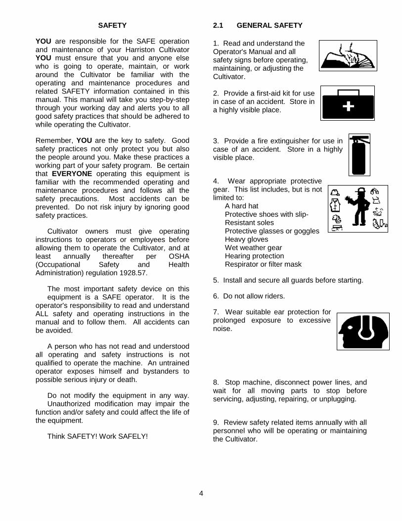
2.1 GENERAL SAFETY 1. Read and understand the Operator's Manual and all safety signs before operating, maintaining, or adjusting the Cultivator. 2. Provide a first-aid kit for use in case of an accident. Store in a highly visible place. 3. Provide a fire extinguisher for use in case of an accident. Store in a highly visible place. 4. Wear appropriate protective gear. This list includes, but is not limited to: A hard hat Protective shoes with slip- Resistant soles Protective glasses or goggles Heavy gloves Wet weather gear Hearing protection Respirator or filter mask 5. Install and secure all guards before starting. 6. Do not allow riders. 7. Wear suitable ear protection for prolonged exposure to excessive noise. 8. Stop machine, disconnect power lines, and wait for all moving parts to stop before servicing, adjusting, repairing, or unplugging. 9. Review safety related items annually with all personnel who will be operating or maintaining the Cultivator.

5
2.2 OPERATING SAFETY
1. Read and understand the Operator's Manual and all safety signs before operating, servicing, adjusting, repairing, or unplugging. 2. Do not allow riders. 3. Install and secure all guards and shields before starting or operating. 4. Keep hands, feet, hair, and clothing away from moving parts. 5.Stop tractor and, and wait for all moving parts to stop before servicing, adjusting, repairing, or unplugging. 6. Do not operate when any guards are damaged or removed. 7. Clear the area of bystanders, especially small children, before starting. 8. Keep all hydraulic lines, fittings, and couplers tight and free of leaks before using. 9. Clean Reflectors, Slow Moving Vehicle, and lights before transporting. 10. Add extra lights and use pilot vehicle when transporting during times of limited visibility. 11. Use hazard flashers on vehicle when transporting. 12. Follow chemical manufacturers’ handling and safety instructions exactly when using chemicals with machine. 13. Review safety instructions with all operators annually.
2.3 MAINTENANCE SAFETY
1. Follow all the operating, maintenance, and safety information in the manual. 2. Support the machine with blocks or safety stands when changing tires or working beneath it. 3. Stop tractor, and wait for all moving parts to stop before servicing, adjusting, repairing, or unplugging. 4. Make sure all guards are in place and properly secured when maintenance work is completed. 5. Never wear ill-fitting, baggy, or frayed clothing when working around or on any of the drive system components. 6. Before applying pressure to a hydraulic system, make sure all lines, fittings, and couplers are tight and in good condition. 7. Wear appropriate protective gear when contacting chemical handling components on machine. 8. Keep hands, feet, hair, and clothing away from moving or rotating parts. 9. Clear the area of bystanders, especially small children, when carrying out any maintenance and repairs or making adjustments.
6
2.4 HYDRAULIC SAFETY
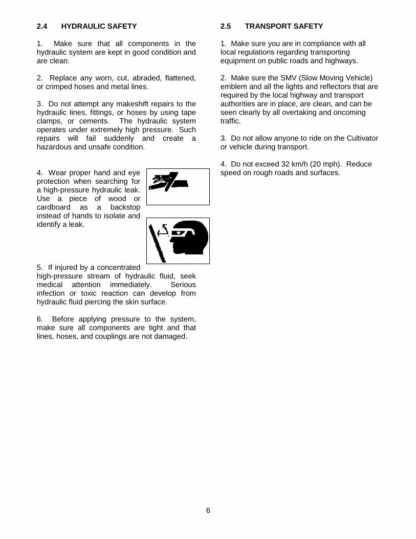
1. Make sure that all components in the hydraulic system are kept in good condition and are clean. 2. Replace any worn, cut, abraded, flattened, or crimped hoses and metal lines. 3. Do not attempt any makeshift repairs to the hydraulic lines, fittings, or hoses by using tape clamps, or cements. The hydraulic system operates under extremely high pressure. Such repairs will fail suddenly and create a hazardous and unsafe condition. 4. Wear proper hand and eye protection when searching for a high-pressure hydraulic leak. Use a piece of wood or cardboard as a backstop instead of hands to isolate and identify a leak. 5. If injured by a concentrated high-pressure stream of hydraulic fluid, seek medical attention immediately. Serious infection or toxic reaction can develop from hydraulic fluid piercing the skin surface. 6. Before applying pressure to the system, make sure all components are tight and that lines, hoses, and couplings are not damaged.
2.5 TRANSPORT SAFETY
1. Make sure you are in compliance with all local regulations regarding transporting equipment on public roads and highways. 2. Make sure the SMV (Slow Moving Vehicle) emblem and all the lights and reflectors that are required by the local highway and transport authorities are in place, are clean, and can be seen clearly by all overtaking and oncoming traffic. 3. Do not allow anyone to ride on the Cultivator or vehicle during transport. 4. Do not exceed 32 km/h (20 mph). Reduce speed on rough roads and surfaces.

7
2.6 STORAGE SAFETY
1. Store away from areas of human activity. Do not permit children to play on or around the stored machine. 2. Make sure the unit is sitting, or blocked up firm and solid and will not tip or sink into a soft area. 3. Cover with weather - proof tarpaulin and tie down securely. 2.7 TIRE SAFETY
1. Failure to follow proper procedures when mounting a tire on a wheel or rim can produce an explosion, which may result in serious injury or death. 2. Do not attempt to mount a tire unless you have the proper equipment and experience to do the job. 3. Have a qualified tire dealer or repair service perform required tire maintenance. 2.8 ASSEMBLY SAFETY
1. Assemble in an area with sufficient space to handle the largest component and access to all sides of machine. 2. Use only lifts, cranes, jacks, and tools, with sufficient capacity for the load. 3. Use two people to handle the large bulky components. 4. Do not allow spectators in the working area.
2.9 SAFETY DECALS
1. Keep safety decals and signs clean and legible at all times. 2. Replace safety decals and signs that are missing or have become illegible. 3. Replaced parts that displayed a safety sign should also display the current sign. 4. Safety decals or signs are available from your Dealer Parts Department. HOW TO INSTALL SAFETY DECALS
1. Be sure that the installation area is clean and dry 2. Decide on the exact position before you remove the backing paper. 3. Remove the smallest portion of the split backing paper. 4. Align the decal over the specified area and carefully press the small portion with the exposed sticky backing in place. 5. Slowly peel back the remaining paper and carefully smooth the remaining portion of the decal in place. 6. Small air pockets can be pierced with a pin and smoothed out using the piece of decal backing paper.

8
2.10 SIGN OFF FORM Harriston Industries follows the general Safety Standards specified by the American Society of Agriculture Engineers (ASAE) and the Occupational Safety and Health Administration (OSHA). Anyone who will be operating and/or maintaining the Cultivator must read and clearly understand All Safety, Operating, and Maintenance information presented in this manual. Do not operate or allow anyone else to operate this equipment until such information has been reviewed. Annually review this information before the season start-up. Make these periodic reviews of Safety and Operation a standard practice for all of your equipment. We feel that an untrained operator is unqualified to operate this machine. A sign-off sheet is provided for your record keeping to show that all personnel who will be working with the equipment have read and understand the information in the Operator’s Manual and have been instructed in the operation of the equipment.
DATE EMPLOYEES SIGNATURE EMPLOYERS SIGNATURE

9
3 Setup
3.1 Toolbar setup Set the tool bar on stands approximately 30” high for ease in assembly. Assembly should be carried out in a flat and open area. 3.2 Marking Toolbar Find the center of the tool bar and mark it. Mark off row spacing on both sides of center mark. For example, if you are setting up a cultivator for 30” rows, mark off every 30” on both sides of center mark. 3.3 Reflectors Place red reflector toward the outside edge of the tool bar facing the rear and the yellow reflector toward outside edge facing forward. 3.4 Three-Point Hitch Center the upper 3 pt. Hitch over the center mark on toolbar and fasten in place with u-bolts, lock washers and nuts. Locate pin in upper hole for category II. Attach the lower hitches, secure with lynch pin. Space the lower hitches 38” apart as shown in the figure for Cat. III.
38" - 1/16"+ 1/16"
Catagory 3
Standing in front of Cultivator
10
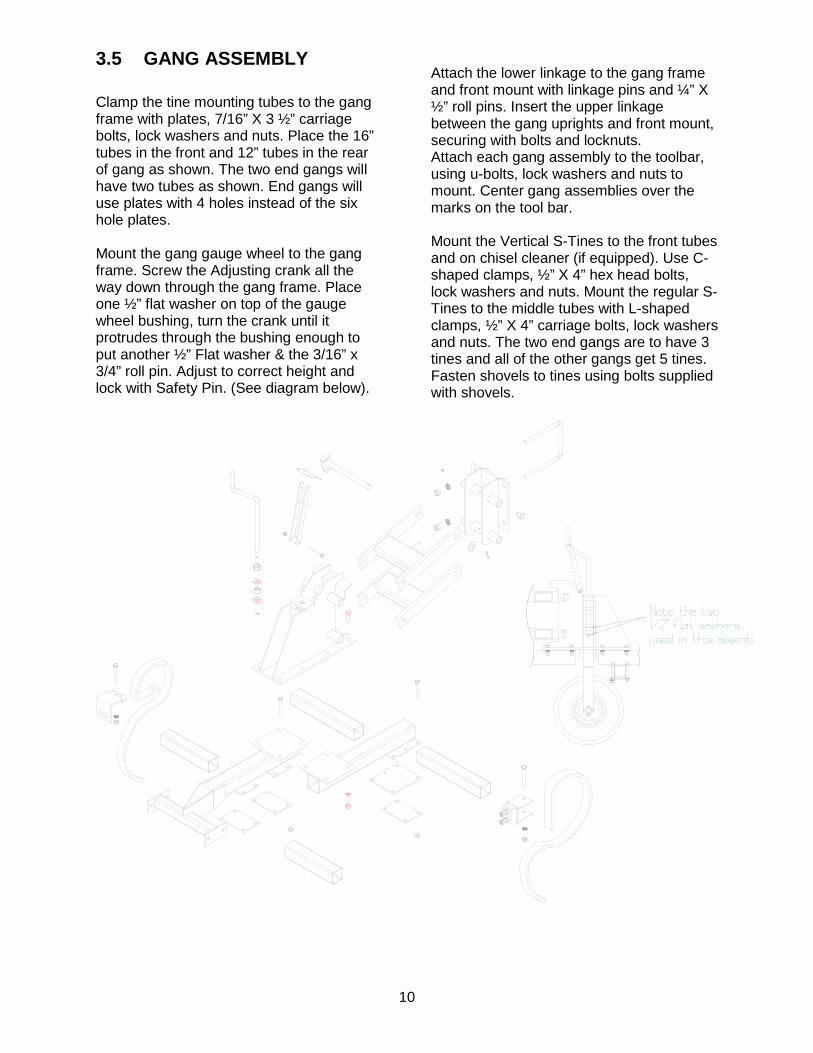
3.5 GANG ASSEMBLY Clamp the tine mounting tubes to the gang frame with plates, 7/16” X 3 ½” carriage bolts, lock washers and nuts. Place the 16” tubes in the front and 12” tubes in the rear of gang as shown. The two end gangs will have two tubes as shown. End gangs will use plates with 4 holes instead of the six hole plates. Mount the gang gauge wheel to the gang frame. Screw the Adjusting crank all the way down through the gang frame. Place one ½” flat washer on top of the gauge wheel bushing, turn the crank until it protrudes through the bushing enough to put another ½” Flat washer & the 3/16” x 3/4” roll pin. Adjust to correct height and lock with Safety Pin. (See diagram below).
Attach the lower linkage to the gang frame and front mount with linkage pins and ¼” X ½” roll pins. Insert the upper linkage between the gang uprights and front mount, securing with bolts and locknuts. Attach each gang assembly to the toolbar, using u-bolts, lock washers and nuts to mount. Center gang assemblies over the marks on the tool bar. Mount the Vertical S-Tines to the front tubes and on chisel cleaner (if equipped). Use C-shaped clamps, ½” X 4” hex head bolts, lock washers and nuts. Mount the regular S-Tines to the middle tubes with L-shaped clamps, ½” X 4” carriage bolts, lock washers and nuts. The two end gangs are to have 3 tines and all of the other gangs get 5 tines. Fasten shovels to tines using bolts supplied with shovels.
11
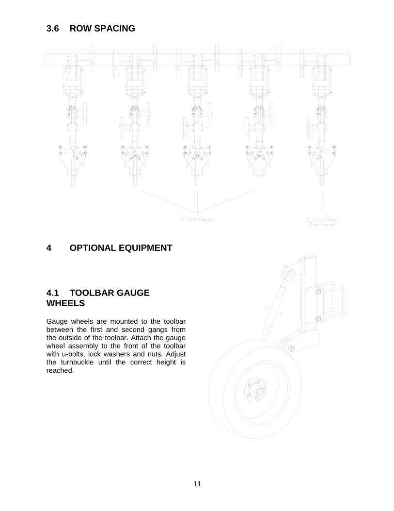
3.6 ROW SPACING
4 OPTIONAL EQUIPMENT
4.1 TOOLBAR GAUGE WHEELS
Gauge wheels are mounted to the toolbar between the first and second gangs from the outside of the toolbar. Attach the gauge wheel assembly to the front of the toolbar with u-bolts, lock washers and nuts. Adjust the turnbuckle until the correct height is reached.
12
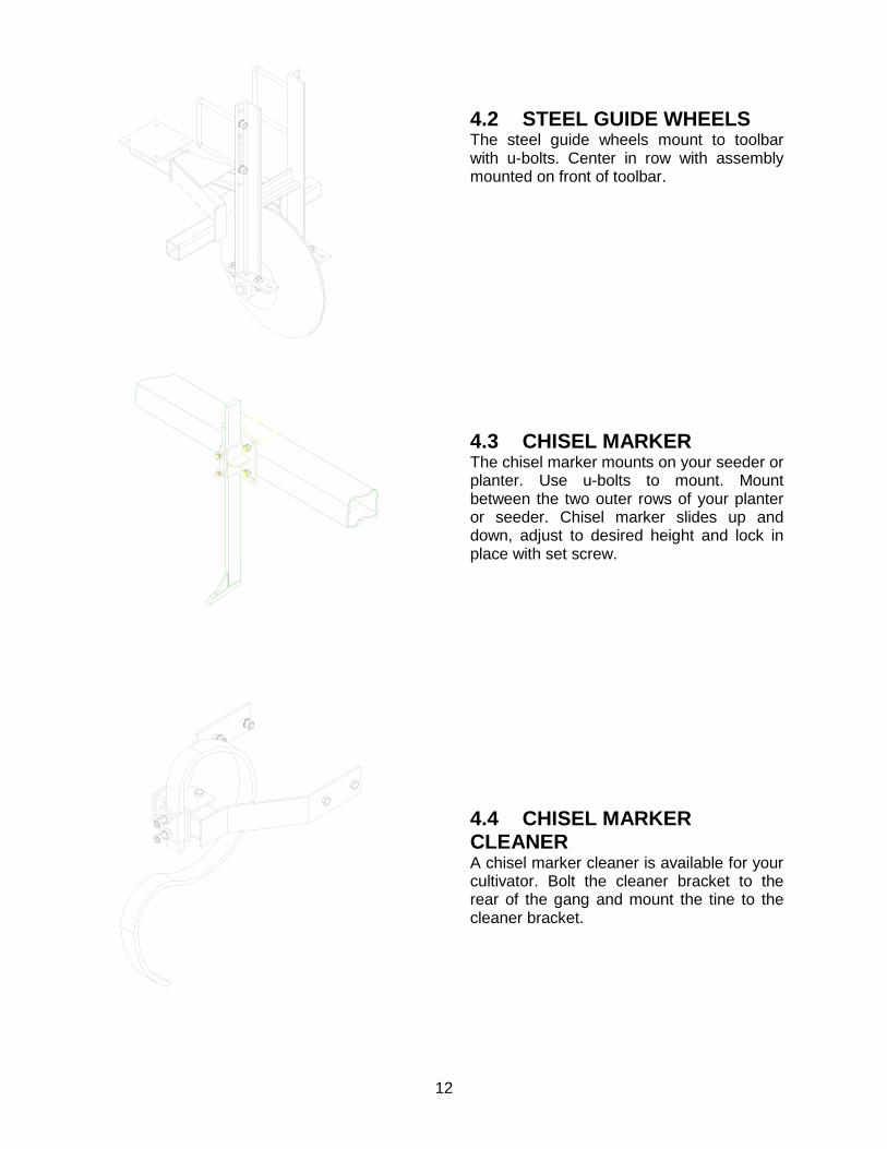
4.2 STEEL GUIDE WHEELS The steel guide wheels mount to toolbar with u-bolts. Center in row with assembly mounted on front of toolbar.
4.3 CHISEL MARKER The chisel marker mounts on your seeder or planter. Use u-bolts to mount. Mount between the two outer rows of your planter or seeder. Chisel marker slides up and down, adjust to desired height and lock in place with set screw.
4.4 CHISEL MARKER CLEANER A chisel marker cleaner is available for your cultivator. Bolt the cleaner bracket to the rear of the gang and mount the tine to the cleaner bracket.
13
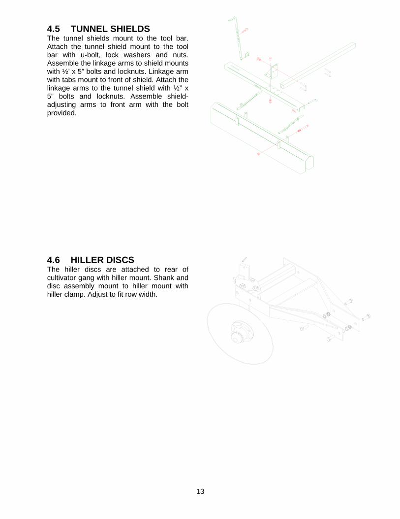
4.5 TUNNEL SHIELDS The tunnel shields mount to the tool bar. Attach the tunnel shield mount to the tool bar with u-bolt, lock washers and nuts. Assemble the linkage arms to shield mounts with ½’ x 5” bolts and locknuts. Linkage arm with tabs mount to front of shield. Attach the linkage arms to the tunnel shield with ½” x 5” bolts and locknuts. Assemble shield-adjusting arms to front arm with the bolt provided.
4.6 HILLER DISCS The hiller discs are attached to rear of cultivator gang with hiller mount. Shank and disc assembly mount to hiller mount with hiller clamp. Adjust to fit row width.
14
5 OPERATION & SERVICE
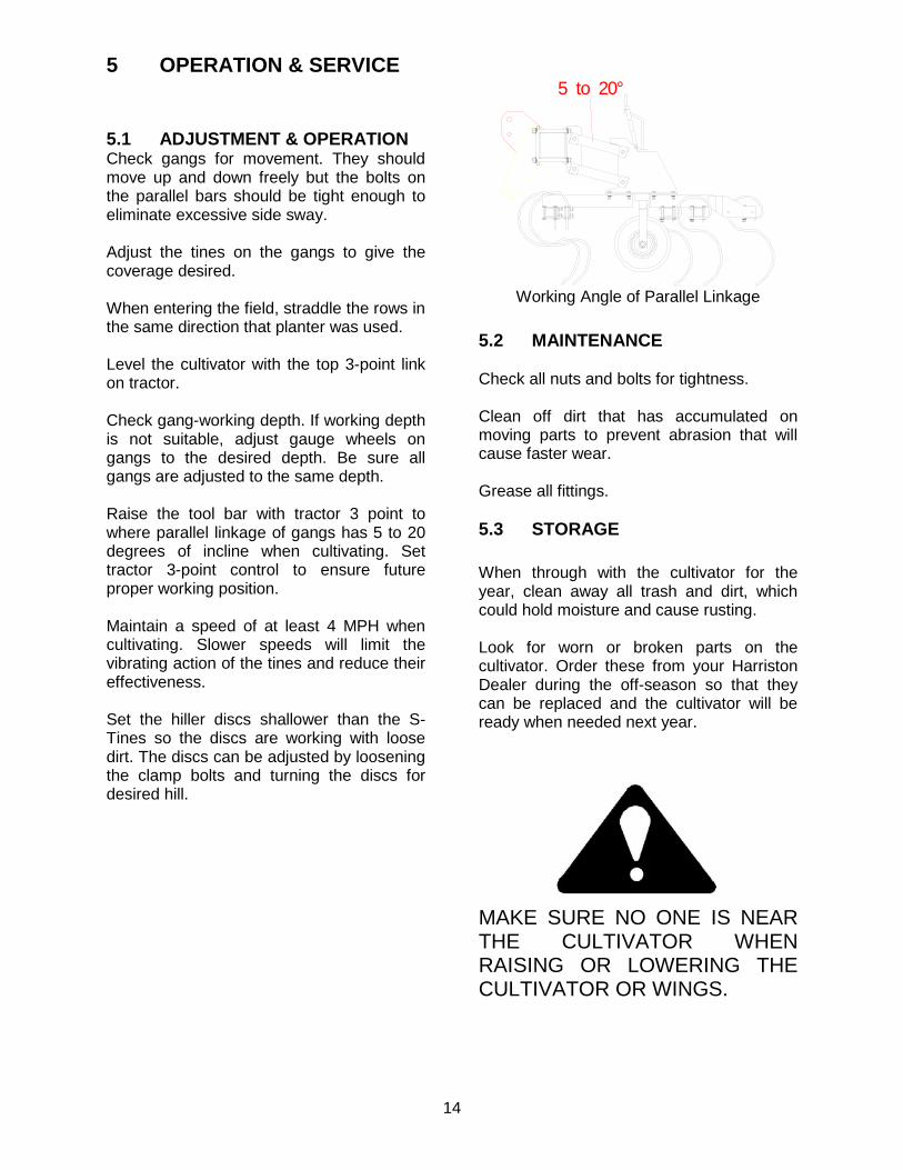
5.1 ADJUSTMENT & OPERATION Check gangs for movement. They should move up and down freely but the bolts on the parallel bars should be tight enough to eliminate excessive side sway. Adjust the tines on the gangs to give the coverage desired. When entering the field, straddle the rows in the same direction that planter was used. Level the cultivator with the top 3-point link on tractor. Check gang-working depth. If working depth is not suitable, adjust gauge wheels on gangs to the desired depth. Be sure all gangs are adjusted to the same depth. Raise the tool bar with tractor 3 point to where parallel linkage of gangs has 5 to 20 degrees of incline when cultivating. Set tractor 3-point control to ensure future proper working position. Maintain a speed of at least 4 MPH when cultivating. Slower speeds will limit the vibrating action of the tines and reduce their effectiveness. Set the hiller discs shallower than the S-Tines so the discs are working with loose dirt. The discs can be adjusted by loosening the clamp bolts and turning the discs for desired hill.
5.2 MAINTENANCE Check all nuts and bolts for tightness. Clean off dirt that has accumulated on moving parts to prevent abrasion that will cause faster wear. Grease all fittings. 5.3 STORAGE When through with the cultivator for the year, clean away all trash and dirt, which could hold moisture and cause rusting. Look for worn or broken parts on the cultivator. Order these from your Harriston Dealer during the off-season so that they can be replaced and the cultivator will be ready when needed next year.
MAKE SURE NO ONE IS NEAR THE CULTIVATOR WHEN RAISING OR LOWERING THE CULTIVATOR OR WINGS.
5 to 20°
Working Angle of Parallel Linkage

15
6 TROUBLESHOOTING
PROBLEM CAUSE SOLUTION CULTIVATOR DRIFTING TO ONE SIDE
3 POINT HITCH NOT CENTERED DIFFERENT SIZE SHOVELS ON DIFFERENT DEPTHS UNEVEN GROUND 3 POINT ON TRACTOR NOT SQUARE TIRE AIR PRESSURE GANGS RUNNING AT UNEVEN DEPTHS
CENTER HITCH USE EQUAL QUANTITIES OF SAME SIZE SHOVELS ON EACH GANG USE GUIDE COULTERS ADJUST LOWER 3 POINT LINKS ON TRACTOR UNTIL CULTIVATOR IS SQUARE TO TRACTOR TIRE AIR PRESSURE 32 POUNDS
UNEVEN PENETRATION OF GANGS
GAUGE WHEELS SET UNEVENLY DIFFERENT SIZE SHOVELS ON DIFFERENT GANGS
SET ALL GAUGE WHEELS AT SAME DEPTH USE EQUAL QUANTITIES OF SAME SIZE SHOVELS ON EACH GANG
UNEVEN FRONT TO REAR TINE PENETRATION
TOOL BAR NOT LEVEL
ADJUST TOP LINK OF 3 POINT HITCH ON TRACTOR
EXCESSIVE SIDE SWAY ON GANGS
WORN PARALLEL BAR BUSHINGS
REPLACE BUSHINGS
GANGS DO NOT MOVE UP AND DOWN FREELY
PARALLEL BAR BOLTS TOO TIGHT
LOOSEN SLIGHTLY
POOR WEED COVERAGE
SHOVEL TOO NARROW SPEED TOO SLOW
USE WIDER SHOVELS INCREASE SPEED (4 TO 7 MPH)
EXCESSIVE SLABBING
HILLER DISCS ARE SET LOWER THAN SHOVELS SHOVELS ARE TOO BIG
RAISE HILLER DISCS SO THE DISCS ARE WORKING WITH LOOSE DIRT PUT ON NARROW SHOVELS
HILL IS TOO HIGH (TOO MUCH DIRT)
CULTIVATOR TOO DEEP DISC NOT ADJUSTED RIGHT
ADJUST GAUGE WHEEL RUN DISC STRAIGHTER
HILL IS TOO SMALL (NOT ENOUGH DIRT)
CULTIVATOR TOO SHALLOW DISC NOT ADJUSTED RIGHT
ADJUST GAUGE WHEEL TO RUN CULTIVATOR DEEPER RUN DISC AT MORE OF AN ANGLE
16
7 PARTS LIST
WHEN ORDERING PARTS Always give your dealer the Model and Serial Number of your machine to assist him in ordering and obtaining the correct parts. Use exploded view and tabular listing of the area of interest to exactly identify the required part. USING THE MANUAL Parts data consists of exploded view illustrations and associated parts list tables, which are read as follows: REFERENCE NUMBER The reference number is the identifier number from the illustration. For example number 3 on an illustration points to a component which is item 3 on the accompanying table. PART NUMBER The Part number is the number by which the component may be Identified and ordered from Harriston Industries and its network of Dealers. DESCRIPTION This column contains the name and description of the part.

17
NOTES:

18
GANG ASSEMBLY #290300
GANG ASSEMBLY
Ref. Part No. Description 1. 270210 Front Mount Weldment 2. 270220 Linkage Weldment 1999 3. 290330 2015/25 Rear Linkage 2005 4. 090155 1” x 7/8” Plastic Insert 5. 200230 Lower Linkage Pin 6. 020965 1/4” x 1-1/2” Spring Lock Pin Plated 7. 021334 Washer 14 gauge x 7/8” 8. 095036 1/4”-28 Straight Zerk
2
1
4
7 6
8
5
3
19
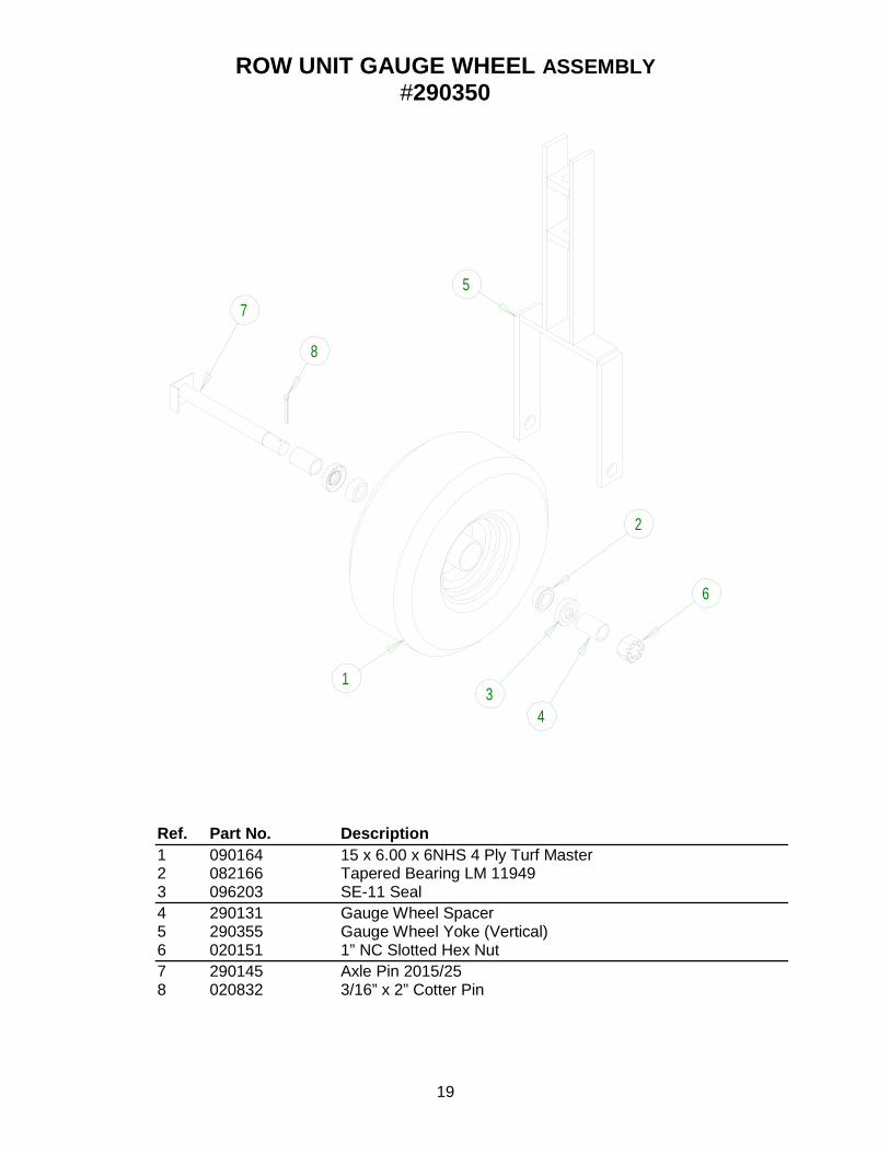
ROW UNIT GAUGE WHEEL ASSEMBLY #290350
Ref. Part No. Description 1 090164 15 x 6.00 x 6NHS 4 Ply Turf Master 2 082166 Tapered Bearing LM 11949 3 096203 SE-11 Seal 4 290131 Gauge Wheel Spacer 5 290355 Gauge Wheel Yoke (Vertical) 6 020151 1” NC Slotted Hex Nut 7 290145 Axle Pin 2015/25 8 020832 3/16” x 2” Cotter Pin
1
5 7
8
2
4 3
6
20
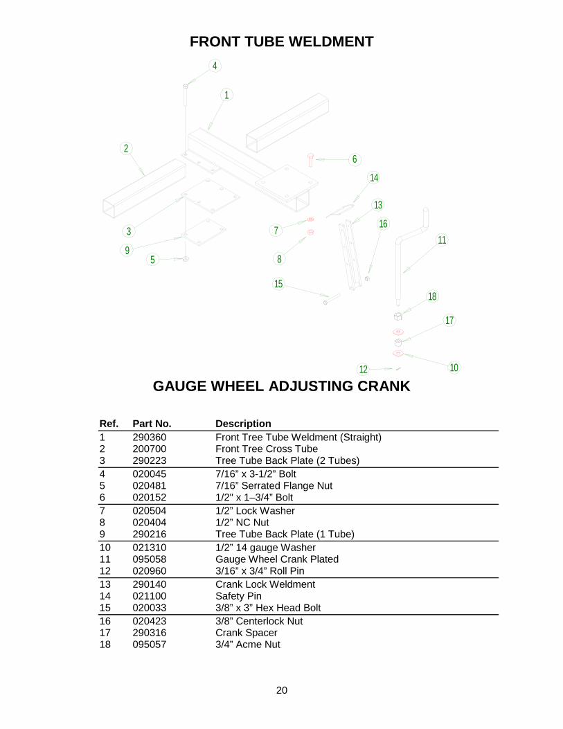
FRONT TUBE WELDMENT
GAUGE WHEEL ADJUSTING CRANK Ref. Part No. Description 1 290360 Front Tree Tube Weldment (Straight) 2 200700 Front Tree Cross Tube 3 290223 Tree Tube Back Plate (2 Tubes) 4 020045 7/16” x 3-1/2” Bolt 5 020481 7/16” Serrated Flange Nut 6 020152 1/2" x 1–3/4” Bolt 7 020504 1/2” Lock Washer 8 020404 1/2” NC Nut 9 290216 Tree Tube Back Plate (1 Tube) 10 021310 1/2” 14 gauge Washer 11 095058 Gauge Wheel Crank Plated 12 020960 3/16” x 3/4” Roll Pin 13 290140 Crank Lock Weldment 14 021100 Safety Pin 15 020033 3/8” x 3” Hex Head Bolt 16 020423 3/8” Centerlock Nut 17 290316 Crank Spacer 18 095057 3/4” Acme Nut
6
4
1
2
3
9 5
7
8
1518
17
1012
14
13
1611
21
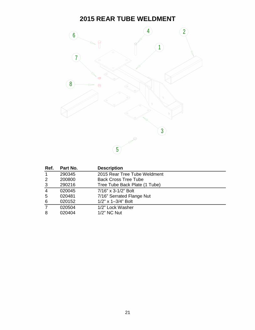
2015 REAR TUBE WELDMENT
Ref. Part No. Description 1 290345 2015 Rear Tree Tube Weldment 2 200800 Back Cross Tree Tube 3 290216 Tree Tube Back Plate (1 Tube) 4 020045 7/16” x 3-1/2” Bolt 5 020481 7/16” Serrated Flange Nut 6 020152 1/2" x 1–3/4” Bolt 7 020504 1/2” Lock Washer
8 020404 1/2” NC Nut
8
7
4
1
2
3
5
6
22
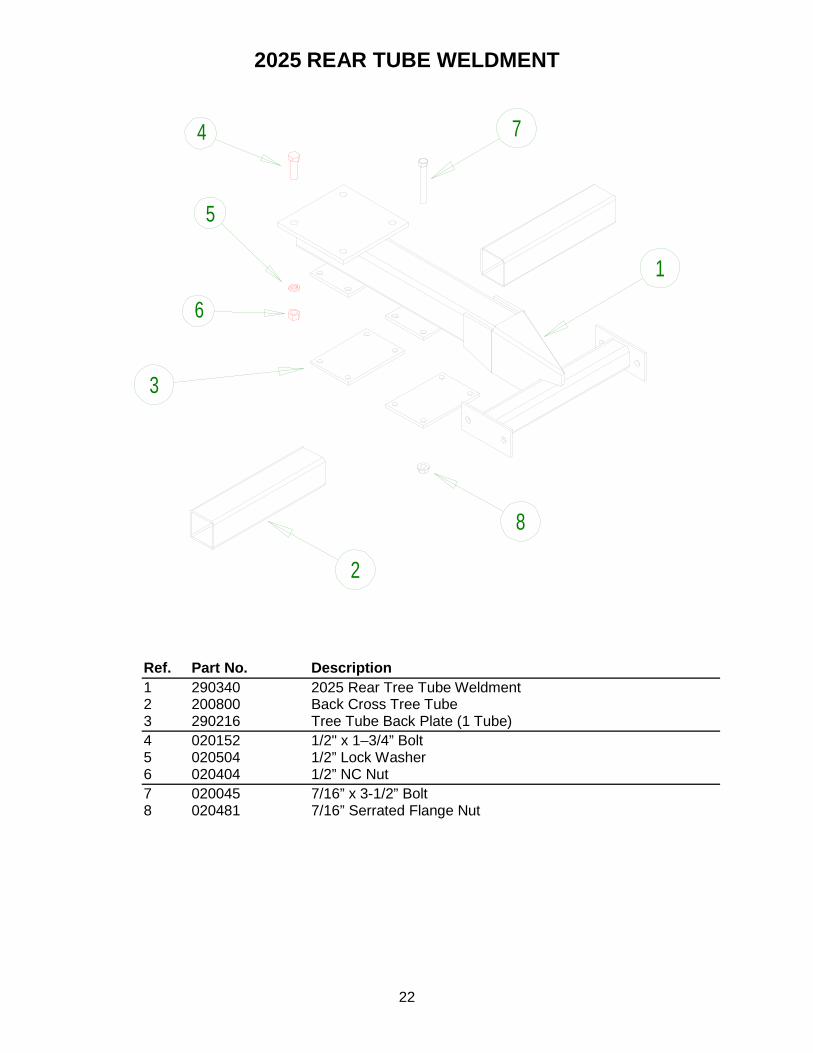
2025 REAR TUBE WELDMENT
Ref. Part No. Description 1 290340 2025 Rear Tree Tube Weldment 2 200800 Back Cross Tree Tube 3 290216 Tree Tube Back Plate (1 Tube) 4 020152 1/2" x 1–3/4” Bolt 5 020504 1/2” Lock Washer 6 020404 1/2” NC Nut 7 020045 7/16” x 3-1/2” Bolt 8 020481 7/16” Serrated Flange Nut
3
2
8
74
6
5
1
23
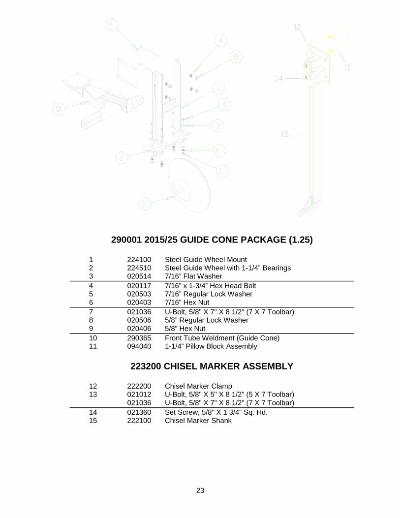
290001 2015/25 GUIDE CONE PACKAGE (1.25)
1 224100 Steel Guide Wheel Mount 2 224510 Steel Guide Wheel with 1-1/4” Bearings 3 020514 7/16” Flat Washer 4 020117 7/16” x 1-3/4” Hex Head Bolt 5 020503 7/16” Regular Lock Washer 6 020403 7/16” Hex Nut 7 021036 U-Bolt, 5/8" X 7" X 8 1/2" (7 X 7 Toolbar) 8 020506 5/8” Regular Lock Washer 9 020406 5/8” Hex Nut 10 290365 Front Tube Weldment (Guide Cone) 11 094040 1-1/4” Pillow Block Assembly
223200 CHISEL MARKER ASSEMBLY
12 222200 Chisel Marker Clamp 13 021012 U-Bolt, 5/8" X 5" X 8 1/2" (5 X 7 Toolbar) 021036 U-Bolt, 5/8" X 7" X 8 1/2" (7 X 7 Toolbar) 14 021360 Set Screw, 5/8" X 1 3/4" Sq. Hd. 15 222100 Chisel Marker Shank
24
SUPPORT WHEEL PAIR 99 W/TIRES #270330

25
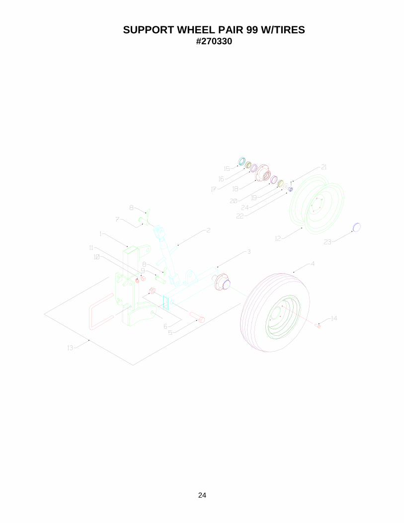
SUPPORT WHEEL PAIR 99 W/TIRES #270330
Ref. Stock No. Description 1 270320 Gauge Wheel Mount Weldment 2 021202 Turnbuckle With Yoke 3 270348 Left Gauge Wheel Arm 270355 Right Gauge Wheel Arm 4 223700 Tire Rim Assembly 205-75-R15 5 020104 Bolt, 1” x 4” NC GR 5 6 020430 Nut, 1” NC Center Lock 7 020898 1” X 3” Clevis Pin ZP 8 020915 3/16” Hair Pin #6 9 020898 1” X 3” Clevis Pin ZP 10 020507 Washer, 3/4” Lock 11 020407 Nut, 3/4” NC 12 090002 15” Rim (Off-White) 13 270340 Support Wheel Assembly Left 270350 Support Wheel Assembly Right 14 021400 W B 10 Wheel Bolts 15 095025 Seal, (Sell) 1 16 095020 Tapered Bearing LM67048 cone 17 095069 Cup, Bearing LM67010 1 18 090012 HA 511, Hub With Cup 19 095019 Tapered Bearing LM11949 Cone 20 095070 Tapered Bearing 3/4" LM 11910 1 21 020827 Cotter Key 22 Nut, Spindle 23 090013 Dust Cap DC 12 24 Washer

26
3-POINT ASSEMBLY
Ref. Part No. Description 1 270440 Upper 3-Point Weldment 2 270420 Lower Right 3 Point Weldment 3 270430 Lower Left 3-Point Weldment 4 021037 3/4” x 7” x 8-½” U-Bolt 5 020093 3/4” x 9” Bolt 6 020507 3/4” Regular Lock Washer 7 020407 3/4” Hex Nut 8 095263 Top Link Pin Category 3 (P7711) 9 228400 Category 3 Bottom 3 Point Pin 10 220900 Top 3 Point Pin 11 095032 7/16” Lynch Pin

27
#211840 Hiller Disc Assembly
Double Bearing
Ref. Part No. Description 1 211876 Dust Cap Strap 2 090015 Dust Cap 3 020490 Castle nut 4 020827 Cotter pin 5 020517 Washer 6 095020 Bearing 7 095069 Bearing cup 8 090210 Hub Casting 9 020421 1/4" lock nut 10 095115 Double Lip Seal 11 211875 Spindle 12 095045 Gasket 13 090024 16" Disc 090023 14" Disc 14 211660 Hiller Shank 15 020415 3/4" nut 16 020003 1/4" bolt 17 211870 Hub Assembly 18 211840 Disc Assy.w/shank 19 211845 Disc with Hub 21 020003 1/4” x 1-1/4” bolt

28
2015 Hiller Discs
Ref. Part No. Description 1 290230 2015 Disc Mount Weldment 2 211930 Disc Clamp 3 211840 Disc Assembly W/ Shank (Double Bearing) 4 020965 1/4 x 1-1/2” Spring Lock Pin 5 020515 1/2” Flat Washer 6 020057 1/2 x 3-1/2” Hex Head Bolt 7 020504 1/2” Regular Lock Washer 8 020404 1/2” Hex Nut 9 020052 1/2” x 1-1/2” Grade 5 Bolt 10 020062 1/2” x 6” Grade 5 Bolt
29
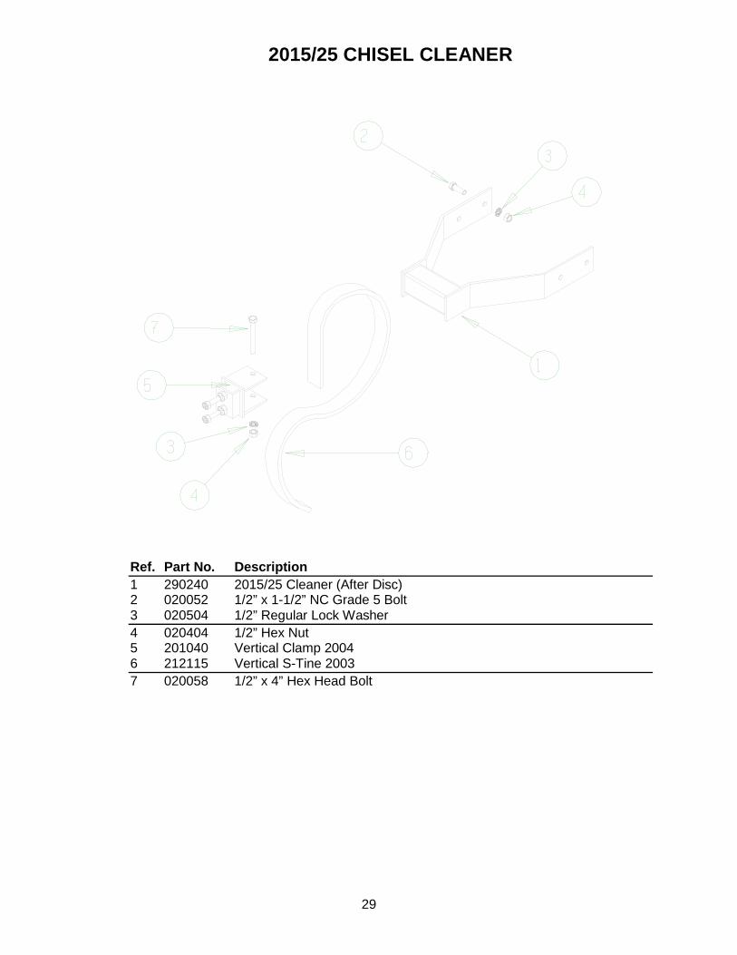
2015/25 CHISEL CLEANER
Ref. Part No. Description 1 290240 2015/25 Cleaner (After Disc) 2 020052 1/2” x 1-1/2” NC Grade 5 Bolt 3 020504 1/2” Regular Lock Washer 4 020404 1/2” Hex Nut 5 201040 Vertical Clamp 2004 6 212115 Vertical S-Tine 2003 7 020058 1/2” x 4” Hex Head Bolt

30
HILLER WING ATTACHMENT
11 9
10
8
7
3
2
1
14
15
16
5
6
1910
18
22
1920
21
23
24
10
18
26
25
27
4
12
1713

31
Hiller Wing Attachment Ref. Part No. Description 1 095139 Hiller Shovel (Ag Mate) 2 204055 Hiller Wing Mount Weldment 3 204032 Hiller Plow Shank 27" Note 4 204000 Hiller Plow Trip Assembly 5 204040 Hiller Plow Shank Assembly 6 290285 Hiller Plow Frame Weldment '03 7 204020 Plow Shank Pivot Mount Weldment 8 095084 Extension Spring 9 300700 1/2" x 8" Eyebolt 10 020404 Nut, 1/2" NC 11 020083 Bolt, 3/4" x2-1/2" NC GR #5 12 020428 Nut, 3/4" NC Lock 13 020967 1/4" x 2" Spring Lock Pin Plain 14 020657 Bolt, 1/2" x 5" NC GR 5 Carriage 15 020053 Bolt, 1/2" x 2" NC GR #5 16 095136 Plow Hiller Blade Left 095137 Plow Hiller Blade Right 17 204064 Wing Pin 18 020504 Washer, 1/2" Lock 19 020515 Washer, 1/2" Flat 20 020053 Bolt, 1/2" x 2 21 020655 Bolt, 1/2" x 2-1/2" Carriage 22 204060 Hiller Wing Bracket Weldment 23 200800 Back Cross Tree Tube 24 290216 Tree Tube Back Plate (1 Tubes) 25 020152 1/2" x 1-3/4" Hex Head Bolt 26 020045 7/16" x 3-1/2" Bolt 27 020481 7/16" Serrated Flange Nut

32
SPIDER ACCESSORIES Ref. Part No. Description 1. 203100 Spider Mount Bracket 2. 095132 Spider Pivot Clamps 3. 020404 1/2" NC Nut 4. 020504 1/2" Lock Washer 5. 021038 1/2" X 2 1/2" X 3-1/4" U-Bolt 6. 200800 Back Cross Tree Tube 7. 201040 Vertical Clamp 2004 8. 212115 Vertical S-Tine 2003 9. 095130 #1 Spider Unit 095131 #2 Spider Unit 10. 290290 2015/2025 Spider Mount Weldment 11. 020052 1/2” x 1-1/2” Bolt 12. 020058 1/2” x 4” Hex Head Bolt 13. 020152 1/2" x 1-3/4” Bolt
234
56
8
4
7
7
9
1
3
43
10
11
3 4
13

33
SPIDER ACCESSORIES CONT. Ref. Part No. Description 1 020432 3/4" Nylock Nuts 2 211685 Spider Shank Weldment Right 211686 Spider Shank Weldment Left 3 095036 1/4" 28 Straight Zerk 4 095101 Terog Hub Bearing 5 095102 Terog Hub Seal 6 095103 Terog Snap Ring 7 095104 Terog Hub Bushing 8 211675 Painted Spider (Right) 9 211676 Painted Spider (Left) 10 211670 Spider C/W Shank (Right) 211671 Spider C/W Shank (Left)

34
TUNNEL SHIELD ASSEMBLY

35
Tunnel Shield Assembly Ref. Part No. Description 1 210100 Tunnel Shield Weldment 2 210400 Tunnel Shield Linkage 3 210300 Tunnel Shield Linkage with Mount Tabs 4 020062 1/2" X 6" bolt 5 020425 1/2" NC Lock Nut 6 02102 1/2" X 3" Clevis Pin 7 020033 3/8" X 3" Bolt 8 020423 3/8 NC Lock Nut 9 210230 Tunnel Shield Support Weldment 10 210240 Adjustment Frame Weldment 11 20876 3/8" X 3" Clevis Pin 12 020911 #2 Bridge Pin 13 021000 1/2" X 2" X 3" U-Bolt 14 020504 1/2" Lock Washer 15 020404 1/2" NC Nut 16 210210 Tunnel Shield Mount Frame 17 020646 7/16" X 3" Carriage Bolt 18 210250 Tunnel Shield Pivot Pin 19 020912 #3 Bridge Pin 20 210220 Tunnel Shield Mount Plate Weldment 21 021018 3/4" X 7" X 6-1/2" U-Bolt 22 020507 3/4" Lock Washer 23 020407 3/4" NC Nut 24 020448 7/16" Jam Nut

36
TUNNEL SHIELD ASSEMBLY (2004) #2104

37
TUNNEL SHIELD ASSEMBLY (2004) #2104
Ref. Part No. Description 1 210760 Tunnel Shield Handle 2 020916 1/4” clips #219 3 020917 1/4” x 2” Lock Pin 4 021000 1/2” x 2” x 3” U-Bolt 5 210780 Tunnel Shield 98 Mount Tube 6 290295 Tunnel Shield Mount Weldment 7 020118 Bolt, 1/2” x 1-1/4” NC 8 020405 Washer, 1/2” Lock 9 020404 Nut, 1/2” NC 10 210728 Tunnel Shield Pin 98 ZP 11 210750 Tunnel Shield Mount Channel 12 210740 Parallel Link Weldment W/Tab 13 020913 .120 Bridge Pin #4 14 210730 Parallel Link Weldment 98 15 020062 1/2” x 6” Bolt 16 210720 Tunnel Shield Weldment 98 17 020425 Nut, 1/2” Lock

38
Shanks & Shovel Options Ref. Stock No. Description 1. 212100 Heavy S-tine 2. 201000 2-1/2" S-Tine clamp 3. 020658 Carriage bolt 1/2" X 4" 4. 020504 1/2" Lock Washer 5. 020404 1/2" NC Nut 6. 212600 Shovel, 4" Heart Shaped 7. 212500 Shovel, 7" 8. 212700 Shovel, 10" 9. 212300 Shovel, 2-3/4" 10. 212400 Shovel, 4" 11. 212200 1-1/2" S-Tine Shovel 12. 213800 Shovel Bolt with Nut 13. 212115 Vertical S-Tine 2003 14. 201040 Vertical Clamp 2004 15. 020058 1/2” x 4” Hex Head Bolt
39
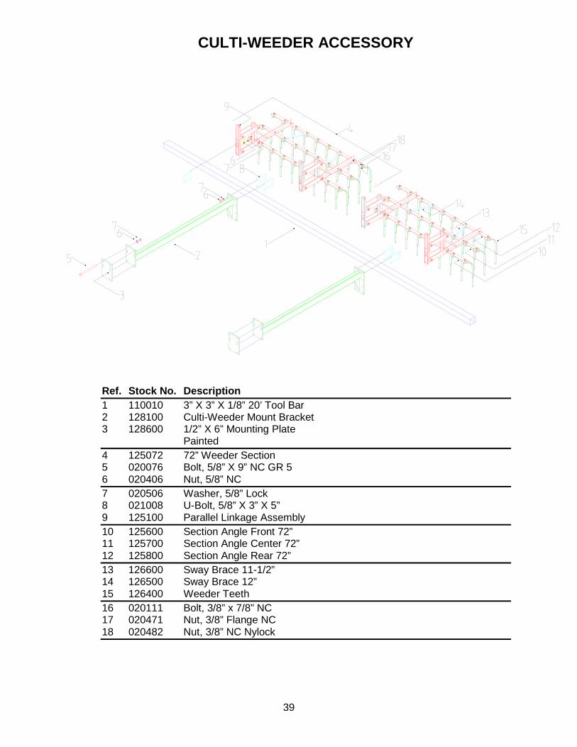
CULTI-WEEDER ACCESSORY
Ref. Stock No. Description 1 110010 3” X 3” X 1/8” 20’ Tool Bar 2 128100 Culti-Weeder Mount Bracket 3 128600 1/2” X 6” Mounting Plate Painted 4 125072 72” Weeder Section 5 020076 Bolt, 5/8” X 9” NC GR 5 6 020406 Nut, 5/8” NC 7 020506 Washer, 5/8” Lock 8 021008 U-Bolt, 5/8” X 3” X 5” 9 125100 Parallel Linkage Assembly 10 125600 Section Angle Front 72” 11 125700 Section Angle Center 72” 12 125800 Section Angle Rear 72” 13 126600 Sway Brace 11-1/2” 14 126500 Sway Brace 12” 15 126400 Weeder Teeth 16 020111 Bolt, 3/8” x 7/8” NC 17 020471 Nut, 3/8” Flange NC 18 020482 Nut, 3/8” NC Nylock

40
111750 8 ROW FOLD PACKAGE
Ref. Stock No. Description 1 111717 Cylinder Pin 2 020965 1/4” x 1-1/2” Spring Lock Pin 3 111610 Hinge Pin 4 020967 1/4” x 2” Spring Lock Pin 5 095036 1/4” 28 Straight Zerk 6 095087 3 1/2” x 16” Cylinder 3516DB 7 095017 1/2” MPT x 3/8” Swivel Elbow 8 095003 3/8” IPT Solid Male 3/8” Hose End 9 095008 3/8” Restrictor 61 SA-06 x 06-32 10 095010 3/8” 1 Wire Hose 11 095016 3/8” NPT Steel Tee 12 095006 1/2” Solid Male 3/8” Hose End 13 095012 Universal Male Tip 1/2” Pioneer End
Front
41
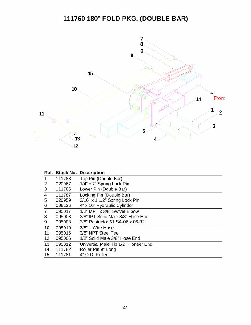
111760 180° FOLD PKG. (DOUBLE BAR)
Ref. Stock No. Description 1 111783 Top Pin (Double Bar) 2 020967 1/4” x 2” Spring Lock Pin 3 111785 Lower Pin (Double Bar) 4 111787 Locking Pin (Double Bar) 5 020959 3/16” x 1 1/2” Spring Lock Pin 6 096126 4” x 16” Hydraulic Cylinder 7 095017 1/2” MPT x 3/8” Swivel Elbow 8 095003 3/8” IPT Solid Male 3/8” Hose End 9 095008 3/8” Restrictor 61 SA-06 x 06-32 10 095010 3/8” 1 Wire Hose 11 095016 3/8” NPT Steel Tee 12 095006 1/2” Solid Male 3/8” Hose End 13 095012 Universal Male Tip 1/2” Pioneer End 14 111782 Roller Pin 9” Long 15 111781 4” O.D. Roller
Front
1 2
6
78
9
11
1213
10
45
14
15
3

42

43
8 INDEX
I Introduction .......................................... 2
O Operation & Service ........................... 14 Optional Equipment ............................ 11
Chisel Marker .................................. 12 Chisel Marker Cleaner .................... 12 Hiller Discs ...................................... 13 Steel Guide Wheels ........................ 12 Tool Bar Gauge Wheels .................. 11 Tunnel Shields ................................ 13
P Parts Section ...................................... 16
180° Folding Toolbar ....................... 41 2015 Rear Tube Weldment ............. 21 2025 Rear Tube Weldment ............. 22 8 Row Folding Toolbar .................... 40 Chisel Cleaner ................................ 29 Chisel Marker .................................. 23 Cultiweeder Accessory ................... 39 Front Tube Weldment ..................... 20 Gang Assembly ............................... 18 Guide Cone ..................................... 23 Hiller Disc Assembly ....................... 27 Hiller Discs ...................................... 28 Hiller Wing Attachment ................... 30 Row Unit Gauge Wheel Assembly .. 19 Shanks (S-Tines) ............................ 38 Shovels ........................................... 38 Spider Accessories ......................... 32 Support Wheels .............................. 24 Three Point Assembly ..................... 26 Tunnel Shield .................................. 34
S Safety ................................................... 3
Assembly .......................................... 7 Decals ............................................... 7 General ............................................. 4 Hydraulic ........................................... 6 Maintenance ..................................... 5 Operating .......................................... 5 Storage ............................................. 7 Tire .................................................... 7 Transport........................................... 6
Setup .................................................... 9 Sign Off Form ....................................... 8
T Table of Contents ................................. 1 Trouble Shooting ................................ 15

Box 378, Minto, ND 58261 (800)437-8205 (701)248-3286
Fax: (701)248-3070 [email protected] www.harriston-mayo.com
PRINTED IN USA ISSUE DATE: February 2007