current-split estimation in li-ion battery pack: an...
TRANSCRIPT
SUBMITTED FOR PUBLICATION TO: , OCTOBER 13, 2015 1
Current-Split Estimation in Li-Ion BatteryPack: An Enhanced Weighted Recursive
Filter MethodHaris M. Khalid, Member, IEEE , Qadeer Ahmed, Member, IEEE
Jimmy C.-H. Peng, Member, IEEE, and Giorgio Rizzoni, Fellow, IEEE
Abstract
Li-ion battery pack is a complex system consisting of numerous cells connected in parallel and
series. The performance of the pack is highly dependent on the health of each individual in-pack
cell. An overcharged or discharged cell connected in a parallel string could change the total capacity
of the battery pack. In a pack, current-split estimation plays an important role to monitor the cell
functions. Therefore, a scheme is required to estimate current-split accurately, which can thereby
help to improve the overall pack performance. To what follows, a recursive weighted-covariance
based estimation method (RWEM) was proposed to estimate the current-split of each set of parallel
connected cells. RWEM assigns weights to the interconnected cell structure by using correlation
information between battery parameters in order to estimate the current-split. This was achieved by
first deriving the one-step prediction error method, where consistency for covariance was proved.
Furthermore, iterative recursion for sparse measurements was also considered. Performance eval-
uations were conducted by analyzing sets of real-time measurements collected from Li-ion battery
pack used in electric vehicles (EV). Results show that the proposed filter accurately estimated the
battery parameters even in the presence of faults and random noise variances.
Index Terms
Covariance, current-split, electric vehicles (EVs), estimation, recursive, Li-ion batteries.
This work was developed on the data generated from Center of Automotive Research, The Ohio State University, USA. Theexperiments were supported by US NSF Grant.
H. M. Khalid and J. C.-H. Peng are with Department of Electrical Engineering and Computer Science, Institute Center forEnergy, Masdar Institute of Science and Technology (MI), Masdar City, U.A.E. (e-mail: mkhalid,[email protected])
Q. Ahmed and G. Rizzoni are with Center for Automotive Research, The Ohio State University (OSU), Columbus, OH 43210USA (e-mail: ahmed.358,[email protected])
ACRONYMS AND ABBREVIATIONSBMS Battery Management System
EKF Extended Kalman filterEV Electric VehicleKF Kalman filter
Li-ion Lithium ionMSE Mean Square ErrorOSV Open source voltagePF Particle filter
RWEM Recursive weighted covariance-based estimation methodSOC State-of-chargeUKF Unscented Kalman filterUPF Unscented particle filterc1 Cell 1c2 Cell 2C capacity of fused form of cells c1 and c2IC0 initial condition of the state of currentFt model matrix of the state response of currentαt temperature transition matrix of temperatureΓ c1t temperature of Cell 1
Γ c2t temperature of Cell 2βt impedance transition matrixzc1t impedance of Cell 1zc2t impedance of Cell 2Gt noise transition matrixwt random process noiset time instantT number of time instantsyt observation output of state of currentp number of simultaneous observations for estimationHt observation matrix of current stateICt current state matrixνt observation noise.Rt residual covarianceδgh Kronecker deltaQt process noise correlation factorIc1t individual current of Cell c1Ic2t individual current of Cell c2V C1,t individual voltage of Cell c1
V C2,t individual voltage of Cell c2
Γ c1t
0, Γ c2t
0 room temperature for Cells c1 and c2
zc1t0, zc2t
0 standard values of impedanceRe,t residual covariance matrixyt observation output of current state
Ac2t , Ac2
t weighted matrices of the current-splitP CI,t|t correlation between the current estimates
I. INTRODUCTION
LI-ION batteries have become one of the preferred energy storage options in the field of EV
applications. They have gained popularity because of their high energy density, light weight,
and longer performance life [1]. To meet the power capacity and voltage requirements of EVs, the
battery pack is composed of more than hundreds of Li-ion cells connected in-series or in-parallel.
2

However, each cell may exhibit variations in terms of capacity, temperature, dynamics, and aging
characteristics. This may be due to adopted production technology, tolerances, material defects,
and contaminations. Moreover, in actual working conditions, the temperature distribution among
cells is also different due to the arrangement and position of cells. All these factors can eventually
result to a lapse in uniformity between the individual cells, which may be reflected by the SOC
divergence1 or internal resistance2 [2]. To keep the Li-ion battery system safe from these issues,
BMS has been proposed at component-level [4–6] and system-level [7].
Moreover, an accurate estimation of the parameters of each battery cell can protect the battery
pack from becoming overcharged or discharged, thereby extending the service life and minimizing
the effects of available energy and power of a battery pack [3]. The in-pack cell with the lowest
available capacity determines the overall rating of the entire pack, because it will be the first to
be completely depleted during the discharging stage. Similarly, the charging of the pack will stop
when the in-pack cell with the lowest available capacity is full, despite others are still not fully
charged. As a result, the power capacity of the entire battery pack will be affected [8–10].
To date, many papers have been published in the literature to address the battery estimation
problem in general [3, 11–24]. They can be classified into OCV-based and battery model-based
methods. OCV-based methods are developed considering the difference of electrical potential be-
tween two terminals of a battery cell or pack. Popular methods are the current integral method [3],
the neural network model method [11], the fuzzy logic method [12], and the support vector-based
estimators [13, 14]. In the battery model-based methods, an approximate battery model is first
developed using the physical laws and equations, and then an algorithm such as the KF [15, 16],
EKF [17–19], UKF [20–22], PF [23] and UPF [24], are proposed to estimate the battery parame-1 SOC divergence determines the magnitude measure of the current state of the battery by analyzing the amount of sink of charge
at a given point.2 Internal resistance of a particular source is the measure of the opposition that a circuit presents to a current when a voltage of
that particular source is applied. A battery may be modeled as a voltage source in series with an internal resistance. In practice, theinternal resistance of a battery is dependent on its size, chemical properties, age, temperature, and the discharge current.
3

ters.
Among published papers, most of the estimation schemes are developed at cell-level. Limited
attention is given at pack-level. Moreover, the estimation schemes do not take into account the
current-split estimation between two parallel cells connected in a series string. This is because
most published methods are highly dependent on the model of the battery cell, where model equa-
tions may not consider the details about the dynamic differences between individual cells. The
incomplete problem analysis can result to oversight of material contamination, variations of tem-
perature, and conductance.
The contribution of this paper is towards enhancing the capacity estimation of the battery pack.
This is accomplished by improving the observability of system parameters of each individual cell.
In control theory, the observability is a measure for how well the internal states of a system can
be inferred by the knowledge of its external outputs [25]. In this paper, we are trying to infer the
current-split by the external outputs of total voltage and current. Also, the electromechanical dy-
namics of the cells are not considered here, instead, cells are considered as conducting bodies only.
The information about battery as conducting bodies parameters is then extracted using a proposed
filter approach named as RWEM. The proposed scheme provides a way to estimate the individual
cell parameters. It is achieved by computing modal parameters from the inputs of battery system
and calculating the current-split in a parallel connected cell structure. Firstly, an initial estimation
of state-prediction is calculated using the prediction error innovation process using (12)–(19). It is
followed by assigning weights to calculate covariance of current-split using (20)–(27). Once the
current-split weighted covariance matrices are achieved, a steady-state value of fused-covariance
matrix is derived for a case of ill-posed or sparse measurements in order to guarantee a feasible
estimation scheme using (28)–(38). The recursive process can also calculate the other dependent
battery parameters. This can be considered as a preventive maintenance strategy to replace the
4

Fig. 1. Framework of RWEM for current-split estimation
effected cell in order to improve the battery pack total capacity. Note the main focus of this pa-
per is to propose a scheme for current-split estimation in battery cells. To achieve this, we have
demonstrated the effectiveness of the proposed algorithm at a constant operating environment tem-
perature of 200C with a single frequency. Moreover, the scheme has been tested on fresh pair of
cells that have minimum manufacturing variability and aging propagation.
The paper is organized as follows: The problem is formulated in Section II. In Section III, the
implementation and evaluation of the scheme are discussed, and finally conclusions are drawn in
Section IV.
5

II. PROBLEM FORMULATION
The formulation begins with outlining the assumed system model, followed by the state rep-
resentation of battery parameters. The RWEM algorithm is then built on it for calculating the
current-split estimates. An overview of the formulation framework of this section is illustrated in
Fig. 1. It summarizes the formulation and equations involved at each step while estimating the
current-split and other parameters of the battery-pack. Note that only two parallel cells connected
in a thread of series are considered here. This is the standard structure used in Li-ion battery
packs [26].
A. State Formulation with Observation Model
Consider a discrete-time dynamical model of a battery-pack at a time t+1 evolved from its
prior state at time t. Two cells connected in parallel with a voltage supply in-series are expressed
as:
ICt+1 = FtICt +
αt
2(Γ c1
t +Γ c2t )+ βt(z
c1t + zc2t )
+ Gtwt, t= 0,1, ...., T (1)
where the superscripts c1 and c2 denote Cell 1 and Cell 2, respectively. The symbol C is used to
present the capacity of fused form of cells c1 and c2, i.e. C = c1 + c2, whereas C ′ presents the
transpose of this fused form. The IC0 ∈ IRr is the initial condition of the state of current, Ft ∈ IRr×r
is a model matrix of the state response of current, such that it depends on covariates, αt ∈ IRr×r
is the temperature transition matrix of temperature Γ c1t ∈ IRr and Γ c2
t ∈ IRr of Cell 1 and Cell 2
respectively. Also, βt ∈ IRr×r is the impedance transition matrix of impedances zc1t ∈ IRr and zc2t
∈ IRr respectively. Gt ∈ IRr×r is the noise transition matrix, which can be defined as a probability
vector whose elements are non-negative real numbers and sum to 1. wt ∈ IRr is the random process
noise, t is the time instant, and T refers to the number of time instants. Let the battery-pack,
6

described in (1), be observed at time-instant t as:
yt =HtFtICt + νt (2)
where yt ∈ IRp is the observation output of state of current, p is the number of simultaneous obser-
vations for estimation made at time instant t, Ht ∈ IRp× r is the observation matrix of current state,
ICt is the current state matrix, and νt ∈ IRp is the observation noise.
It has been initially assumed that the noises wt and νt are uncorrelated, and are zero-mean
white noise sequences with Gaussian distribution:
IE[wt] = IE[νt] = IE[wgν′
h] = 0, ∀ t (3)
IE[wgw′
h] =Rtδgh, IE[νgν′
h] =Qtδgh, ∀ t (4)
Note Rt represents the residual covariance, δgh is a Kronecker delta which is one when variables
g and h are the same. Qt is the process noise correlation factor, and superscript ′ represents the
transpose.
B. Relationship Between Battery Parameters
Once the observation model is extracted from the measurements of the battery pack, the re-
lation between different parameters of the battery are formulated. Note the known parameters of
parallel cells connected in a series string are the string voltages, temperatures and current.
At time instant t, Ic1t is the individual current of Cell c1, and can be represented as the differ-
ence between voltage V C1,t and V C
2,t as:
Ic1t =V C1,t−V C
2,t
zc1t(5)
Similarly, Ic2t is the individual current of Cell c2, and is defined as:
Ic2t =V C1,t−V C
2,t
zc2t(6)
7

Also, impedances zc1t and zc2t for cells c1 and c2 are:
zc1t = zc10
t +[1+αt(Γ
c1t −Γ c10
t )], (7)
zc2t = zc20
t +[1+αt(Γ
c2t −Γ c20
t )]
(8)
Note in (7)–(8), the standard relation between impedance and temperature is considered for Cell
c1 and c2 according to [27]. Here zc1t0 and zc2t
0 are the standard values of impedance at room
temperature Γ c1t
0 and Γ c2t
0 respectively. αt is the transition matrix of temperature. (7) can be
expressed for temperature Γ c1t of Cell 1 as:
Γ c1t =
zc1tαzc1
0
t
− 1
α+Γ c10
t (9)
Similarly, temperature Γc2,t of Cell 2 is:
Γ c2t =
zc2tαzc2
0
t
− 1
α+Γ c20
t (10)
Since Γ Ct =Γ c1
t +Γ c2t
2,
Γ Ct =
zc1t2αtzc1
0
t
+zc2t
2αtzc20
t
+Γ c10
t
2+
Γ c20
t
2− 1
αt
=zc1t zc2
0
t + zc2t zc10
t − 2zc10
t zc20
t
2αtzc10
t zc20
t
+αtΓ
c10
t zc10
t zc20
t +αtΓc20
t zc10
t zc20
t
αtzc10
t zc20
t
(11)
Thus, the general relation between battery parameters is developed.
To find the current-split estimation, the individual state of current ICt needs to be determined.
Note that each Li-ion cell has a nominal voltage of 3.2 V. Hence, any variations will be occurring
in a bounded-capacity, which requires a good initial parameter value estimate. It is particularly
true for this paper as no battery-model is used. Good initial parameter values can provide a good
estimate and improve the ability to predict the dependent battery parameters expressed in (5) to
(11). To achieve this, an uncorrelated innovation process is used to develop confidence intervals
around the prediction profile of the current-split. It is to ensure the best possible approximation of
8

the true system even when the battery model is not available.
C. Prediction of State Vector of Current using by Innovation Process
Given the uncorrelated innovation process, the recursive one-step prediction estimate of ICt
can be presented as:
ICt+1 = (IE[ICT ])RC−1
e,t−1et−1
ICt+1 =t+1∑t−1
(ICt+1, et−1)RC−1
e,t−1et−1 (12)
where Re,t is the residual covariance matrix of the difference between the observation output of
current state yt and its estimate yt, denoted by et = yt −HtICt|t−1. Accordingly, the state of current
can be computed from the most recent past value ICt|t−1 and the new information in e. A more
indicative form of recursion of (12) is:
ICt+1|t=[t+1∑t=0
(ICt+1, et−1)Rc1−1
e,t−1et−1
]+(ICt+1, et)R
c2−1
e,t et (13)
where[∑t+1
t=0(ICt+1, et−1)R
c1−1
e,t−1et−1
]is the estimate of the one-step prediction. Therefore,
ICt+1|t = ICt+1|t−1+(ICt+1, et−1)R−1e,t−1(yt−HtI
Ct|t−1) (14)
which completes the one-step prediction for the state of current, ICt . Considering the difference
between ICt and its estimate ICt as ICt|t, the initial condition of the state of current is:
IC0|0=IC0|0− IC0|0
=F0IC0|0+α0(Γ
c10|0+Γ c2
0|0)+ β0(zc10|0+ zc20|0)+G1w1
−F0IC0|0−(ICt+1, et)R
−1e,t
[Ht(F0I
C0|0 +α0(Γ
c10|0
+Γ c20|0)+ β0(z
c10|0+ zc20|0)+G1w1)+ ν1−H1F0I
C0
](15)
Rearranging (15) gives,
IC0|0=[1−(IC0|0, e1)R−1
e,1H1
]F0I
C0|0+
[1− (IC0 , e1)R
−1e,1H1
]G1w1 −
[1− (IC0 , e1)R
−1e,1H1
]F0I
C0|0+
[1− (IC0 , e1)
9

R−1e,1H1
][α0Γ
c10 +α0Γ
c20
]+[1− (IC0 , e1)R
−1e,1H1
][βzc10|0+βz
c20|0
]− (IC0|0, e1)R
−1e,1ν1 (16)
Hence, the covariance matrix for current difference of Cell 1 and Cell 2 is:
P CI,1|1=IE[Ic11|1I
c2′
1|1 ]=[1− (Ic11|1, e1|1)R
c1−1
e,1|1
]Q0
[1−(Ic21|1, e1|1)
R−1e,1|1
]′
+[1−(IC0|0, e,1|1)R−1
e,1|1
]F0I
C0+
[1−(IC0 , e1)R−1
e,1H1
][βzc10|0 + βzc20|0
]− (IC0|0, e1)R
−1e,1ν1 (17)
Similar to (17), the fused difference of ICt|t can be written as:
ICt|t =[1− (ICt|t, et−1)R
−1e,t−1Ht
]FtI
Ct|t+
[1− (ICt ,
et−1)R−1e,t−1Ht
]Gtwt−
[1− (ICt , et)R
−1e,tHt
]Ft
ICt|t+[1−(ICt , et)R−1
e,tHt
][αtΓ
c1t +αtΓ
c2t
]+[1−
(ICt , et)zc1t|tR
−1e,tHt
][β+βzc2t|t
]− (ICt|t, et)R
−1e,t νt (18)
which yields the covariance matrix for the fused difference of current ICt|t as:
P CI,t|t=
[1−(Ic1t+1, et)R
c1−1
e,t−1Hc1t
]Ft−1P
Ct−1|t−1F
′
t−1[1−(Ic2t+1, et)R
c2−1
e,t−1Hc2t
]F
′
t−1+[1− (Ic2t+1, et)
Rc2−1
e,t−1Hc2t
]′
+[1−(ICt , et)R−1
e,t−1Ht
][αΓ c1
t
+αΓ c2t
]+[1−(ICt , et)R−1
e,t−1Ht
][βzc1t|t+βz
c2t|t
](19)
The initialization of the current states Ic1t and Ic2t was made using the innovation process. How-
ever, the derived covariance matrix assumes that both cells have the same impedance, operating
temperature, and other cell dynamics. This leads to the motivation to consider the problem for
battery pack with dynamic in-cell variations. Variations in the individual cells are primarily due
to cell total capacity, internal resistance, and the initial value of SOC, which gives the reason to
derive a covariance matrix that can represent the dynamical situation of current-split estimation.
10

The proposed solution is to assign weights to the states of current, Ic1t and Ic2t , and calculate a
weighted covariance of current-split with recursion.
D. Weighted Covariance for Estimation of Current-Split
The recursive estimate of the current-split can be represented as a sum of weights:
ICt|t = Ac1t I
c1t +Ac2
t Ic2t (20)
where Ac2t and Ac2
t are the weighted matrices of the current-split. Therefore, the difference between
Ic1t and Ic2t can be expressed by δCt as follows:
δCt = Ic1t|t − Ic2t|t (21)
The expression (21) can be normalized further as:
IE[δCt δC′
t ] = IE[Ic1t|t − ICt|t− (Ic2t|t − ICt|t)][Ic1t|t
− ICt|t− (Ic2t|t − ICt|t)]′
(22)
and is equivalent to:
IE[δCt δC′
t ] = P c1I,t|t+P
c2I,t|t−P C
I,t|t−P C′
I,t|t (23)
The term P CI,t|t refers to the associated covariance of fused current with its estimate ICt|t. Also,
P CI,t|t=IE[(Ic1t|t−ICt )(Ic2t|t−ICt )
′]=IE[Ic1t|t I
c2t|t]=P C′
I,t|t (24)
where P CI,t|t is the correlation between the two current estimates Ic1t and Ic2t , respectively. Using
the calculation from (12)–(19), the weighted matrix of the current-split for Ic1t can be expressed
as:
Ac1t =
(P c2I,t|t−P C′
I,t|t
)(P c1I,t|t+P c2
I,t|t−P CI,t|t−P C′
I,t|t
)−1
(25)
Similarly, the weighted matrix for current-split of Ic2t is:
Ac2t =
(P c1I,t|t−P C
t|t
)(P c1I,t|t+P c2
I,t|t−P CI,t|t−P C′
I,t|t
)−1
(26)
11

Considering (25) and (26), the covariance matrix for the fused current-split is:
P CI,t|t = P C
I,t|t−1−(P c2I,t|t−P C′
I,t|t
)(P c1I,t|t+P c2
I,t|t
− P CI,t|t−P C′
I,t|t
)−1(P c2I,t|t−P C′
I,t|t
)′
(27)
The weights have also been defined in a closed-form in (25) and (26). Note, the covariance matrices
of temperature and voltage can also be calculated by using (5)–(11). In order to satisfy convergence
for the estimator, the fused covariance matrix for the current-split requires a proof of consistency,
which is shown in the Appendix.
However, the current-split information from each individual cell and its respective covariance
matrix are highly dependent on the difference of in-series voltages and the relation between tem-
perature and impedance as noted in (5)–(11). There can be a condition where the current-split
estimation is an ill-posed or sparse problem. This is the case when one of the cells is generating
random zero values, which will make the solution of (25) and (26) infeasible because of the inverse
matrix and closed-form solution. In order to guarantee a feasible estimation, an iterative method is
required to develop which can generate a feasible solution for an ill-posed or sparse data condition.
E. Current-Split Estimation during an Ill-Posed Condition
In this section, a recursive loop is built on top of (20)–(27) to give feedback to the updated
current estimate and its associated covariance at each time-instant. The implicit fused current
estimate can be expressed as:
ICt|t = P CI,t|t
[P c2I,t|tFtI
Ct|t−1+(P c2
I,t|t−P C′
I,t|t)(Pc1I,t|t
+ P c2I,t|t−P C
I,t|t−P C′
I,t|t)−1(P c2
I,t|t−P C′
I,t|t)′]−1
P C′
I,t|t(Ac1t FtI
c1t|t +Ac2
t|tFtIc2t|t) (28)
It can be simplified as:
ICt|t=Ac1T P
CI,t|tA
c1t FtI
c1t|t+A
c2T P
CI,t|tA
c2t FtI
c2t|t (29)
12

where, Ac1T and Ac2
T are the identity matrices, Ac1t =Ac1
t−1PCI,t|t
[P c2I,t|tFtI
Ct|t−1+(P c2
I,t|t−P C′
I,t|t)(Pc1I,t|t+
P c2I,t|t−P C
I,t|t−P C′
I,t|t)−1(P c2
I,t|t−P C′
I,t|t)′]−1
. Also, Ac2t =Ac2
t−1PCt|t
[P c1I,t|tFtI
Ct|t−1+(P c1
I,t|t−P C′
I,t|t)(Pc2I,t|t+
P c1I,t|t−P C
I,t|t−P C′
I,t|t)−1(P c1
I,t|t−P C′
I,t|t)′]−1
. Considering the feedback of the estimate, and comput-
ing with the inverse of the covariance matrix gives:
P C−1
I,t|t ICt|t=−(N − 1)P C−1
I,t|t−1ICt|t−1+
[P c2I,t|t−(P c2
I,t|t
−P C′
I,t|t)(Pc1I,t|t+P
c2I,t|t−P C
I,t|t−P C′
I,t|t)−1(P c2
I,t|t
−P C′
I,t|t)′]−1
(Ac1t I
c1t|t +Ac2
t Ic2t|t) (30)
where N is the number of cells, which is 2 for this formulation. To compute the steady state
error covariance of fused current state estimate ICt|t, subtracting P C−1
t|t from both sides of (30) and
substituting (29) yields:
P C−1
I,t|t (ICt|t− ICt ) =
−P C−1
I,t|t ICt − (N − 1)P C−1
I,t|t−1ICt|t−1 − (N − 1)P C−1
I,t|t−1
ICt|t−1+[P c2I,t|t−(P c2
t|t −P C′
I,t|t)(Pc1I,t|t+P c2
t|t−P CI,t|t−P C′
I,t|t)−1
(P c2I,t|t−ΣC′
t|t)T]−1
(Ac1t I
c1t|t +Ac2
t Ic2t|t) (31)
Rearranging (31) gives:
= −(N − 1)P C−1
I,t|t−1Ft−1(ICt−1|t−1−ICt−1)−P C−1
I,t|t ICt
−(N − 1)P C−1
I,t|t−1Ft−1ICt−1+P
C−1
I,t|t
[At−1P
CI,t|tA
c1t FtI
c1t|t
+ At−1PCI,t|tA
c2t FtI
c2t|t
](32)
Through simple algebra manipulations and substituting (2), we can re-write (31) as
P C−1
I,t|t (ICt|t− ICt ) =[
− (N − 1)P C−1
I,t|t−1Ft+P C−1
t|t At−1PCI,t|tA
c1t Ft+P C−1
I,t|t
AtPCI,t|tA
c2t Ft
](ICt−1|t−1−Ic1t|t−Ic2t|t)+P C−1
I,t|tAt−1PCI,t|tA
c1t
13

FtIc1t−1+P C−1
I,t|tAt−1PCI,t|tA
c2t FtI
c2t|t−1−P C−1
I,t|t ICt
− (N − 1)P C−1
I,t|t−1Ft−1ICt−1 (33)
which develops a recursive loop in order to guarantee feasible solution for the estimator. Further-
more, in order to verify stability, (33) can be written in the form of a discrete Lyapunov equation.
This can be seen in the Appendix.
III. IMPLEMENTATION AND EVALUATION
The proposed estimation scheme was exhaustively assessed on Li-ion battery-pack under dif-
ferent operating conditions. The experiments were carried out at the battery laboratory in the
Center for Automotive Research (CAR) [28] according to the guidelines issued by United States
Department of Energy battery test manual [29,30]. Three of the studies are presented in this paper.
Each study presents a structure of cells connected in parallel in a series thread as shown in Fig.
2. Test Case I analyzed the nominal values collected from the parallel structure of cells in Fig.
2(a). The proposed method is referenced with two main stream techniques: 1) Extended Kalman
filter [31,32], and 2) Unscented Kalman filter [33]. Test Case II examined the cell structure shown
in Fig. 2(b) with random noise variance. This was followed by Test Case III, which considered a
current-split estimation in the presence of injected fault. Note the implementation was preferred to
test offline because of two main reasons: Firstly, a fault injection can be detected by a BMS. This
detection may result in system shut-off or a compensation of the fault. Secondly, if the BMS is un-
available to detect the fault, the injected fault may result in potential damage to battery. Therefore,
to be able to cover the whole set of considered faults in a consistent way, the off-line approach has
been chosen. In all three test cases, the characterized battery cell is a cylindrical A123 ANR26650
Li-ion iron-phosphate (LiFePO4) cell with a nominal capacity of 2.3 Ah and a nominal voltage
of 3.2 V. The experimental setup is composed of 800W programmable electronic load, 1.2 kW
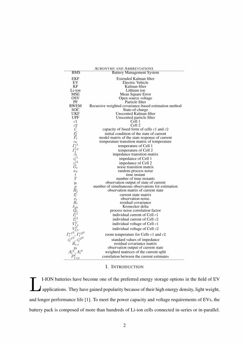
programmable power supply, a data acquisition unit for collecting measurement signals, a thermal14
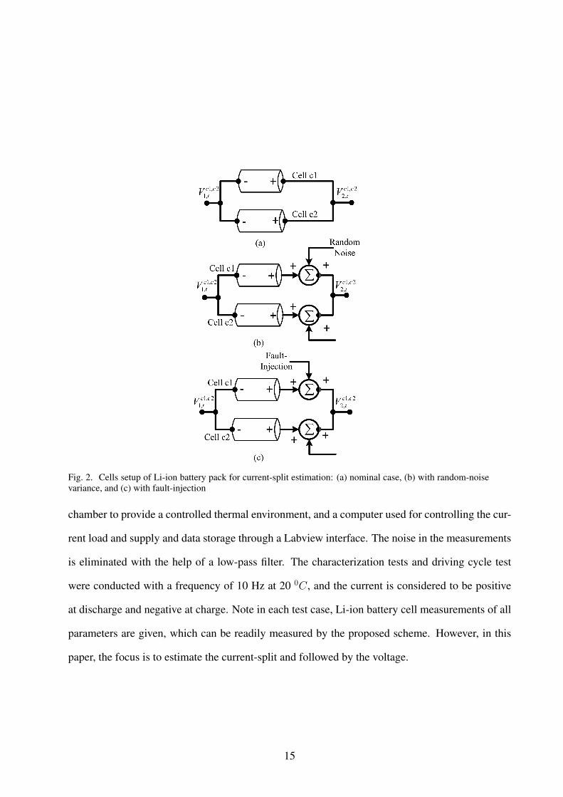
Fig. 2. Cells setup of Li-ion battery pack for current-split estimation: (a) nominal case, (b) with random-noisevariance, and (c) with fault-injection
chamber to provide a controlled thermal environment, and a computer used for controlling the cur-
rent load and supply and data storage through a Labview interface. The noise in the measurements
is eliminated with the help of a low-pass filter. The characterization tests and driving cycle test
were conducted with a frequency of 10 Hz at 20 0C, and the current is considered to be positive
at discharge and negative at charge. Note in each test case, Li-ion battery cell measurements of all
parameters are given, which can be readily measured by the proposed scheme. However, in this
paper, the focus is to estimate the current-split and followed by the voltage.
15

A. Test Case I: Nominal Current-Split Estimation
The purpose of this study is to examine the estimation capability of the proposed scheme for
the current-split of two cells in parallel. The online values of all the parameters of the battery for
the two cells are plotted in Fig. 3. It comprises of the sampled current given to two cells, individual
current of each cell for testing and verifying our estimation scheme, corresponding voltage profile
and temperature during battery charging/discharging operation.
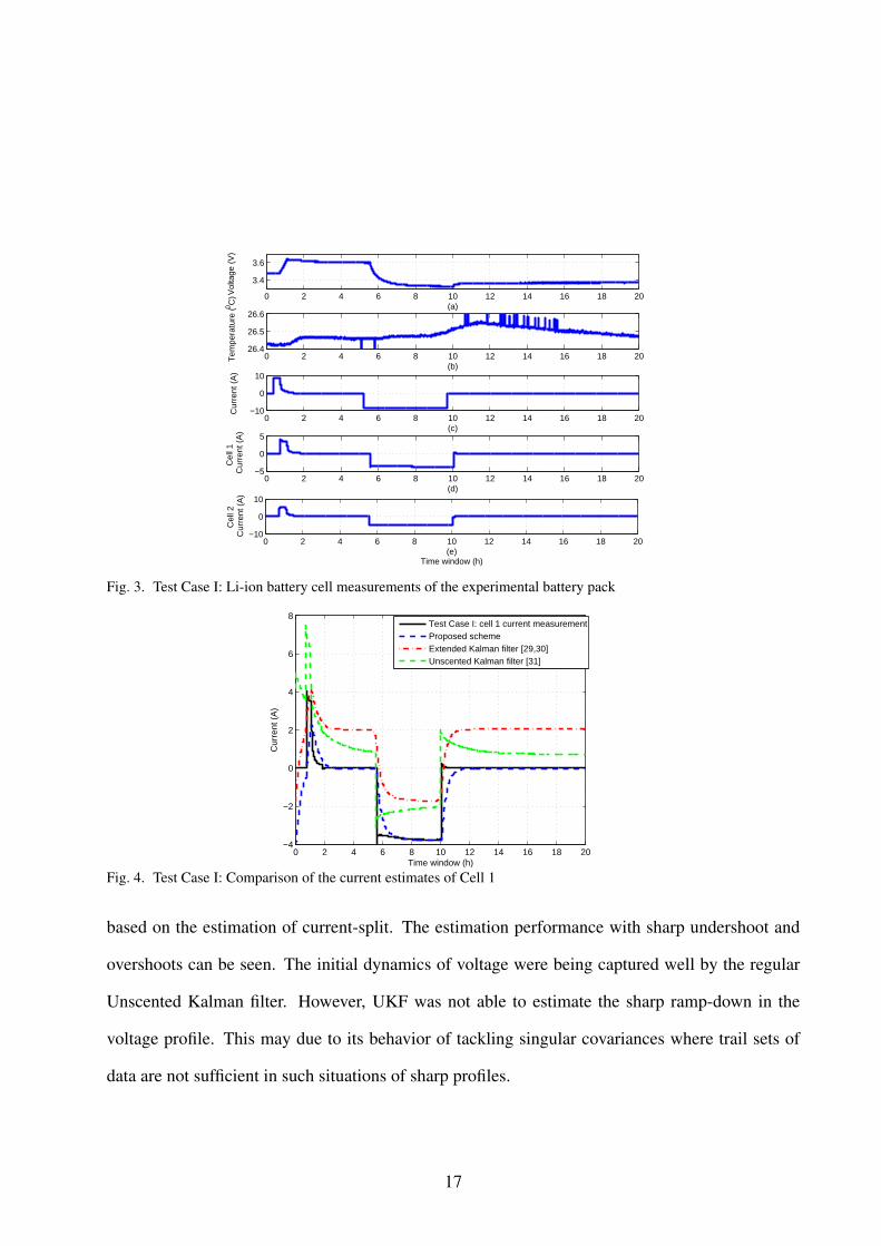
The proposed estimation scheme was implemented to estimate the current-split from the real
time measurements of the Li-ion battery cells. This was followed by the calculation of voltage
values based on the estimated current-split. Referring to Fig. 4 and 5, the proposed recursive
weighted covariance-based filter is used to estimate the respective profiles of current from Cell 1
and Cell 2, respectively. In addition, comparisons with the mainstream Unscented Kalman filter
of [33] were made. Referring to Fig. 4 and 5, there is a huge over-shoot spike at the beginning
of the measured current in each cell. The proposed filter captured such dynamics more clearly
than the regular Unscented Kalman filter. Furthermore, a comparison of MSE and error percentage
between the main stream UKF [33], and EKF [31, 32] and the proposed filter is shown in Fig. 6.
All the techniques performed reasonably well. However, because of the initialization procedure,
the EKF started with a slow time tracking response, causing it to have a higher MSE value in the
initial time windows. This is due to the lack in updating the covariance matrix at every iteration,
which is not the case for UKF. It performed better than EKF. However, the initial overshoot was
not well-captured by the UKF. In contrast, the recursive-based weighted filter was fast enough to
capture the dynamics well from the start. Therefore, the proposed method gives more accurate
results than EKF UKF as it was able to estimate the deviations of the profile with precision. This
is due to its estimating nature using the innovation process used for the initialization.
Referring to Fig.7, the voltage of the circuit has been estimated. This voltage was calculated
16
0 2 4 6 8 10 12 14 16 18 20
3.4
3.6
Vol
tage
(V
)
(a)
0 2 4 6 8 10 12 14 16 18 2026.4
26.5
26.6
Tem
pera
ture
(0 C)
(b)
0 2 4 6 8 10 12 14 16 18 20−10
0
10
Cur
rent
(A
)
(c)
0 2 4 6 8 10 12 14 16 18 20−5
0
5
C
ell 1
Cur
rent
(A
)
(d)
0 2 4 6 8 10 12 14 16 18 20−10
0
10
C
ell 2
Cur
rent
(A
)
(e)Time window (h)
Fig. 3. Test Case I: Li-ion battery cell measurements of the experimental battery pack
0 2 4 6 8 10 12 14 16 18 20−4
−2
0
2
4
6
8
Time window (h)
Cur
rent
(A
)
Test Case I: cell 1 current measurementProposed schemeExtended Kalman filter [29,30]Unscented Kalman filter [31]
Fig. 4. Test Case I: Comparison of the current estimates of Cell 1
based on the estimation of current-split. The estimation performance with sharp undershoot and
overshoots can be seen. The initial dynamics of voltage were being captured well by the regular
Unscented Kalman filter. However, UKF was not able to estimate the sharp ramp-down in the
voltage profile. This may due to its behavior of tackling singular covariances where trail sets of
data are not sufficient in such situations of sharp profiles.
17

0 2 4 6 8 10 12 14 16 18 20−6
−4
−2
0
2
4
6
8
10
Time window (h)
Cur
rent
(A
)
Test Case I: Cell 2 current measurementProposed schemeExtended Kalman filter [29,30]Unscented Kalman filter [31]
Fig. 5. Test Case I: Comparison of the current estimates of Cell 2
0−2 2−4 4−6 6−8 8−10 10−12 12−14 14−16 16−18 18−2010
−4
10−2
100
Time window(h)(a)
MS
E
Test Case I: MSE Comparison of cell 1 current
MSE−EKF [29,30]MSE−UKF [31]MSE−Proposed scheme
0−2 2−4 4−6 6−8 8−10 10−12 12−14 14−16 16−18 18−2010
−4
10−2
100
Time window(h)(b)
MS
E
Test Case I: MSE Comparison of cell 2 current
1.76% error
5.41% error
3.15% error
5.65% error 3.67% error2.18% error
Fig. 6. Test Case I: MSE performance of estimated current for a) Cell 1, and b) Cell 2
0 2 4 6 8 10 12 14 16 18 20
3.25
3.30
3.35
3.40
3.45
3.5
Time window (h)
Vol
tage
(V
)
Test Case I: voltage measurementExtended Kalman filter [29,30]Proposed schemeUnscented Kalman filter [31]
Fig. 7. Test Case I: Estimated voltage of battery cell
18

B. Test Case II: Current-split Estimation with Random Noise Variance
The objective of this test case is to examine the estimation capacity of the proposed scheme
in the presence of random noise variance. The sampled current profile of the parallel circuit and
each individual cell, temperature variations, and the corresponding voltage trajectory are shown in
Fig. 8. Random noise with a variance between 0.1 and 0.9 was added in the current measurements.
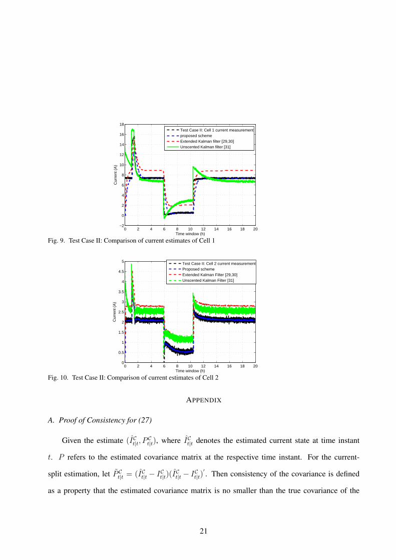
Referring to Fig. 9 and 10, the noise variance has introduced some spikes in the current profile. A
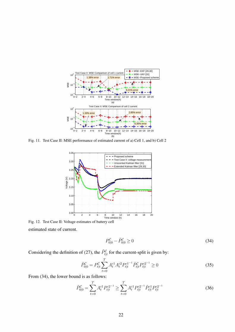
comparison of the corresponding MSE and percentage error between the main-stream EKF, UKF,
and the proposed filter is shown in Fig. 11. In Fig.7, the voltage was estimated. Because of the
random noise variance, the voltage dynamics for this case are showing a signature of sinusoid
kind of fluctuation. The dynamics of voltage were being captured well by the regular Unscented
Kalman filter. Furthermore, a comparison of MSE is shown in Fig. 11. All the schemes performed
reasonably well. However, EKF and UKF were not able to estimate the fault thoroughly. EKF may
have suffered due to its property of using predefined model for finite difference approximation by
calculating Jacobians. Whereas, UKF considers a Gaussian-noise uniformity in the model profile,
which was not the case here.
C. Test Case III: Current-split Estimation with Fault-Injection
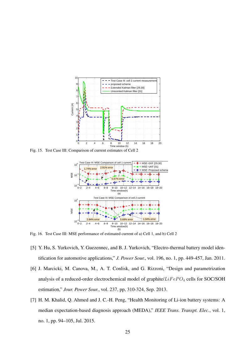
This test case has been generated to evaluate the performance of the proposed filter in the
presence of injected fault. The sampled individual and cumulative current profile can be seen in
Fig. 13, followed by profile for temperature variations and voltage. Random faults were injected in
the current profile at 6.25–7.5 hours and 10.8–11.75 hours. Fig. 14 and 15 show the current-split
profile with fault injection scenarios. The corresponding MSE and percentage error between the
main stream EKF, UKF, and the proposed filter is shown in Fig. 16. From these figures, EKF and
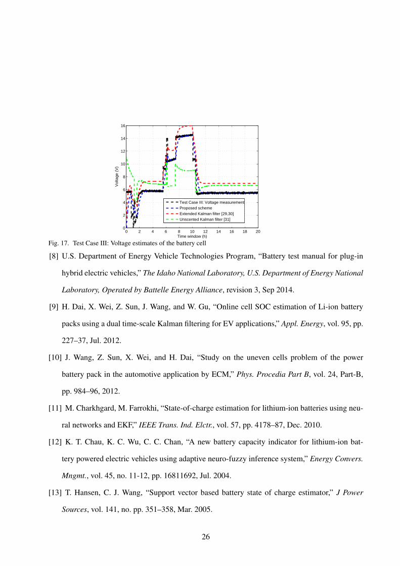
UKF are not able to estimate the kinks and outliers accurately in the current profiles. Meanwhile,
the estimated cumulative voltage outputs are shown in Fig. 17. The same pattern of kinks and
19

0 2 4 6 8 10 12 14 16 18 203
3.5
4
Vol
tage
(V
)
(a)
0 2 4 6 8 10 12 14 16 18 2024.4
24.6
24.8
Tem
pera
ture
(0 C
)
(b)
0 2 4 6 8 10 12 14 16 18 20−10
0
10
Cur
rent
(A
)
(c)
0 2 4 6 8 10 12 14 16 18 20−10
0
10
C
ell 1
Cur
rent
(A
)
(d)
0 2 4 6 8 10 12 14 16 18 20−5
0
5
C
ell 2
Cur
rent
(A)
(e)Time window (h)
Fig. 8. Test Case II: Li-ion battery cell measurements with random-noise variance
outliers like in Fig. 14 and 15 can also be seen in this profile followed by the estimation analysis.
IV. CONCLUSIONS
The proposed RWEM-based current-split estimation has been effectively demonstrated to es-
timate current-split against random noise conditions and fault injections. The weighted covariance
property of the proposed scheme was incorporated in the initialization of the filter with the inno-
vation process. These enhancements provide more strength to the filter. In the future, an adaptive
scheme to estimate the current-split of cells will be proposed to benefit the cell-balancing control
of each individual cell to improve the service life of the battery-pack. Moreover, the testing of
battery pack cells at different temperatures, varying frequencies and aged cells is one of our high
priority agenda for future work.
20
0 2 4 6 8 10 12 14 16 18 20−2
0
2
4
6
8
10
12
14
16
18
Time window (h)
Cur
rent
(A
)
Test Case II: Cell 1 current measurementproposed schemeExtended Kalman filter [29,30]Unscented Kalman filter [31]
Fig. 9. Test Case II: Comparison of current estimates of Cell 1
0 2 4 6 8 10 12 14 16 18 200
0.5
1
1.5
2
2.5
3
3.5
4
4.5
5
Time window (h)
Cur
rent
(A
)
Test Case II: Cell 2 current measurementProposed schemeExtended Kalman Filter [29,30]Unscented Kalman Filter [31]
Fig. 10. Test Case II: Comparison of current estimates of Cell 2
APPENDIX
A. Proof of Consistency for (27)
Given the estimate (ICt|t, PCt|t), where ICt|t denotes the estimated current state at time instant
t. P refers to the estimated covariance matrix at the respective time instant. For the current-
split estimation, let P Ct|t = (ICt|t − ICt|t)(I
Ct|t − ICt|t)
′ . Then consistency of the covariance is defined
as a property that the estimated covariance matrix is no smaller than the true covariance of the
21
0−2 2−4 4−6 6−8 8−10 10−12 12−14 14−16 16−18 18−2010
−4
10−2
100
Time window(h)(a)
MS
E
Test Case II: MSE Comparison of cell 1 current
MSE−EKF [29,30]MSE−UKF [31]MSE−Proposed scheme
0−2 2−4 4−6 6−8 8−10 10−12 12−14 14−16 16−18 18−2010
−4
10−2
100
Time window(h)(b)
MS
E
Test Case II: MSE Comparison of cell 2 current
1.38% error 2.71% error
5.21% error
1.33% error 2.85% error
5.35% error
Fig. 11. Test Case II: MSE performance of estimated current of a) Cell 1, and b) Cell 2
0 2 4 6 8 10 12 14 16 18 203.00
3.05
3.10
3.15
3.20
3.25
3.30
3.35
Time window (h)
Vol
tage
(V
)
Proposed schemeTest Case II: voltage measurementUnscented Kalman filter [31]Extended Kalman filter [29,30]
Fig. 12. Test Case II: Voltage estimates of battery cell
estimated state of current.
P C0|0− P C
0|0 ≥ 0 (34)
Considering the definition of (27), the P Ct|t for the current-split is given by:
P C0|0 = P C
t|t
T∑t=0
Ac1t A
c2t P
c1−1
t|t P Ct|tP
c2−1
t|t ≥ 0 (35)
From (34), the lower bound is as follows:
P C0|0 =
T∑t=0
Ac1t P
c2−1
t|t ≥T∑t=0
Ac1t P
c2−1
t|t P c1t|tP
c2−1
t|t (36)
22

As Ac2t A
c1t ≥ 0, this follows that:
P c2−1
t|t P c2t|tP
c2−1
t|t +P c1−1
t|t P c1t|tP
c1−1
t|t −P c2−1
t|t P C′
t|tPc1−1
t|t −P c1−1
t|t
P Ct|tP
c2−1
t|t = IE[(P c2−1
t|t Ic2t|t −P c1−1
t|t Ic1t|t)(Pc2−1
t|t Ic2t|t −P c1−1
t|t
Ic1t|t)′]≥ 0 (37)
B. Proof of Stability for (33)
Using (33), the discrete Lyapunov equation can be expressed as:
MΩM′+Ω = 0 (38)
where M ′ is the conjugate transpose of M . Given that Ω > 0, satisfying (38), if and only if the
linear system ICt+1 = FtICt is asymptotically stable. (33) can be represented in the form of (38),
where:
M = limt→∞
P CI,t|t
[− (N − 1)P C−1
I,t|t−1Ft+P C−1
I,t|tAt−1
P CI,t|tA
c1t Ft+P C−1
I,t|tAt−1PCI,t|tA
c2t Ft
],Ω =WtRtW
′
t ,
Wt = limt→∞
[P CI,t|tP
C−1
I,t|tAt−1PCI,t|t
](Ac1
t +Ac2t )
REFERENCES
[1] M. Dubarry, B. Y. Liaw, M. S. Chen, S. S. Chyan, K. C. Han, W. T. Sie, and S. H. Wu,
“Identifying battery aging mechanisms in large format Li-ion cells,” J. Power Sources, vol.
196, no. 7, pp. 3420–3425, Apr. 2011.
[2] M. Dubarry, N. Vuillaume, Y. B. Liaw, “Origins and accommodation of cell variations in Li-
ion battery pack modeling,” Int. J. Energy Res, vol. 34, pp. 216–31, Dec. 2009.
[3] K. S. Ng, C.-S. Moo, Y.-P. Chen, and Y-C. Hsieh, “Enhanced coulomb counting method for
23

0 2 4 6 8 10 12 14 16 18 20
3.4
3.6
Vol
tage
(V
)
(a)
0 2 4 6 8 10 12 14 16 18 2024.7
24.8
24.9
Tem
pera
ture
(0 C
)
(b)
0 2 4 6 8 10 12 14 16 18 20−10
0
10
Cur
rent
(A
)
(c)
0 2 4 6 8 10 12 14 16 18 20−5
05
C
ell 1
Cur
rent
(A
)
(d)
0 2 4 6 8 10 12 14 16 18 20−5
0
5
Cel
l 2C
urre
nt (
A)
(e)Time window (h)
Fig. 13. Test Case III: Li-ion battery cell measurements under fault injections
0 2 4 6 8 10 12 14 16 18 200
2
4
6
8
10
12
Time window (h)
Cur
rent
(A
)
Proposed schemeTest Case III: Cell 1 measurementExtended Kalman filter [29,30]Unscented Kalman filter [31]
Fig. 14. Test Case III: Comparison of current estimates of Cell 1
estimating state-of-charge and state-of-health of lithium-ion batteries,” Appl. Energy, vol. 86,
no. 9, pp. 1506–1511, Sep. 2009.
[4] Z. Liu, Q. Ahmed, G. Rizzoni, and H. He, “Fault detection and isolation for lithium-ion bat-
tery system using structural analysis and sequential residual generation,” 7th ASME Annual
Dynamic Sys. and Ctrl., TX, US, 2014.
24
0 2 4 6 8 10 12 14 16 18 200
1
2
3
4
5
6
7
8
9
10
Time window (h)
Cur
rent
(A
)
Test Case III: cell 2 current measurementproposed schemeExtended Kalman filter [29,30]Unscented Kalman filter [31]
Fig. 15. Test Case III: Comparison of current estimates of Cell 2
0−2 2−4 4−6 6−8 8−10 10−12 12−14 14−16 16−18 18−2010
−4
10−2
100
Time window(h)(a)
MS
E
Test Case III: MSE Comparison of cell 1 current
MSE−EKF [29,30]MSE−UKF [31]MSE−Proposed scheme
0−2 2−4 4−6 6−8 8−10 10−12 12−14 14−16 16−18 18−2010
−5
100
Time window(h)(b)
MS
E
Test Case III: MSE Comparison of cell 2 current
1.74% error 2.91% error
5.67% error
2.84% error 5.69% error 1.04% error
Fig. 16. Test Case III: MSE performance of estimated current of a) Cell 1, and b) Cell 2
[5] Y. Hu, S. Yurkovich, Y. Guezennec, and B. J. Yurkovich, “Electro-thermal battery model iden-
tification for automotive applications,” J. Power Sour., vol. 196, no. 1, pp. 449-457, Jan. 2011.
[6] J. Marcicki, M. Canova, M., A. T. Conlisk, and G. Rizzoni, “Design and parametrization
analysis of a reduced-order electrochemical model of graphite/LiFePO4 cells for SOC/SOH
estimation,” Jour. Power Sour., vol. 237, pp, 310-324, Sep. 2013.
[7] H. M. Khalid, Q. Ahmed and J. C.-H. Peng, “Health Monitoring of Li-ion battery systems: A
median expectation-based diagnosis approach (MEDA),” IEEE Trans. Transpt. Elec., vol. 1,
no. 1, pp. 94–105, Jul. 2015.
25
0 2 4 6 8 10 12 14 16 18 200
2
4
6
8
10
12
14
16
Time window (h)
Vol
tage
(V
)
Test Case III: Voltage measurementProposed schemeExtended Kalman filter [29,30]Unscented Kalman filter [31]
Fig. 17. Test Case III: Voltage estimates of the battery cell
[8] U.S. Department of Energy Vehicle Technologies Program, “Battery test manual for plug-in
hybrid electric vehicles,” The Idaho National Laboratory, U.S. Department of Energy National
Laboratory, Operated by Battelle Energy Alliance, revision 3, Sep 2014.
[9] H. Dai, X. Wei, Z. Sun, J. Wang, and W. Gu, “Online cell SOC estimation of Li-ion battery
packs using a dual time-scale Kalman filtering for EV applications,” Appl. Energy, vol. 95, pp.
227–37, Jul. 2012.
[10] J. Wang, Z. Sun, X. Wei, and H. Dai, “Study on the uneven cells problem of the power
battery pack in the automotive application by ECM,” Phys. Procedia Part B, vol. 24, Part-B,
pp. 984–96, 2012.
[11] M. Charkhgard, M. Farrokhi, “State-of-charge estimation for lithium-ion batteries using neu-
ral networks and EKF,” IEEE Trans. Ind. Elctr., vol. 57, pp. 4178–87, Dec. 2010.
[12] K. T. Chau, K. C. Wu, C. C. Chan, “A new battery capacity indicator for lithium-ion bat-
tery powered electric vehicles using adaptive neuro-fuzzy inference system,” Energy Convers.
Mngmt., vol. 45, no. 11-12, pp. 16811692, Jul. 2004.
[13] T. Hansen, C. J. Wang, “Support vector based battery state of charge estimator,” J Power
Sources, vol. 141, no. pp. 351–358, Mar. 2005.
26

[14] Q. S. Shi, C. H. Zhang, N. X. Cui, “Estimation of battery state-of-charge using v-support
vector regression algorithm,” Int. J. Automot. Tech., vol. 9, no. 6, pp. 759–64, Dec. 2008.
[15] D. Andre, C. Appel, T. Soczka-Guth, D. U. Sauer, “Advanced mathematical methods of SOC
and SOH estimation for lithium-ion batteries,” J. P. Sources, vol. 224, pp. 2027, Feb. 2013.
[16] H. Dai, X. Wei, Z. Sun, “State and parameter estimation of a HEV Li-ion battery pack us-
ing adaptive Kalman filter with a new SOCOCV concept,” Proc. IEEE Int. Conf. meas. tech.
mechatr. autom., pp. 375–380, Apr. 2009.
[17] G. L. Plett, “Extended Kalman filtering for battery management systems of LiPB-based HEV
battery packs- Part 3: State and parameter estimation,” J. Power Sources, vol. 134, pp. 277292,
2004.
[18] G. L. Plett, “Extended Kalman filtering for battery management systems of LiPBbased HEV
battery packs- Part 2: Modeling and identification,” J. Power Sources, vol. 134, no. 2, pp.
262–276, Aug. 2004.
[19] J. Y. Han, D. C. Kim, M. Sunwoo, “State-of-charge estimation of lead-acid batteries using an
adaptive extended Kalman filter,” J. Power Sources, vol. 188, no. 2, pp. 606–612, Mar. 2009.
[20] F. Sun, X. Hu, Y. Zou, S. Li, “Adaptive unscented Kalman filtering for state of charge esti-
mation of a lithium-ion battery for electric vehicles,” Energy, vol. 36, no. 5, pp. 3531–40, May
2011.
[21] G. L. Plett, “Sigma-point Kalman filtering for battery management systems of LiPB-based
HEV battery packs: Part 1: Introduction and state estimation,” J. Power Sources, vol. 161, no.
2, pp. 1356–68, Oct. 2006.
[22] S. Santhanagopalan, and R. E. White, “State of charge estimation using an unscented filter
for high power lithium ion cells,” Int. J. Energy Res., vol. 34, pp. 152–63, Dec. 2009.
[23] S. Schwunk, N. Armbruster, S. Straub, J. Kehl, M. Vetter, “Particle filter for state of charge
27

and state of health estimation for lithiumiron phosphate batteries,” J. Power Sources, vol. 239,
pp. 705–10, Oct. 2013.
[24] Y. He, X. Liu, C. Zhang, Z. Chen, “A new model for State-of-Charge (SOC) estimation for
high-power Li-ion batteries,” Appl. Energy, vol. 101, pp. 808–814, Jan. 2013.
[25] K. J. Astrom, and R. M. Murray, “Feedback systems: An introduction for scientists and
engineers,” Princeton University Press, 2008.
[26] A. C.-Arenas, S. Onori, G. Rizzoni, “A control-oriented lithium-ion battery pack model for
plug-in hybrid electric vehicle cycle-life studies and system design with consideration of health
management,” J. Power Sources, vol. 279, pp. 791–808, Apr. 2015.
[27] “Standard handbook for electrical engineers,” by H. W. Beaty (Editor), and D. G. Fink (Edi-
tor), Aug. 2012.
[28] Y. Hu, S. Yurkovich, Y. Guezennec, and B. J. Yurkovich, “Electro-thermal battery model
identification for automotive applications,” J. Power Sour., vol. 196, no. 1, pp. 449-457, Jan.
2011.
[29] J. Marcicki, M. Canova, M., A. T. Conlisk, and G. Rizzoni, “Design and parametrization
analysis of a reduced-order electrochemical model of graphite/LiFePO4 cells for SOC/SOH
estimation,” J. Power Sour., vol. 237, pp, 310-324, Sep. 2013.
[30] “Battery test manual for Plug-In hybrid electric vehicles,” U.S. Dept. Ener. Vehicle Tech.
Program, Revision 0, Mar. 2008.
[31] A. Singh, A. Izadian, and S. Anwar, “Adaptive nonlinear model-based fault diagnosis of Li-
ion Batteries,” IEEE Trans. Indus. Elect., Article in Press, vol. 62, no. 2, pp. 1002–1011, Jul.
2014.
[32] H. He, R. Xiong, X. Zhang, F. Sun, and J. Fan, “State-of-Charge estimation of the lithium-
ion battery using an adaptive extended Kalman filter based on an improved Thevenin model,”
28

IEEE Trans. Vehi. Tech., vol. 60, no. 4, pp. 1461–1469, May 2011.
[33] H. Hea, R. Xiong, and J. Peng, “Real-time estimation of battery state-of-charge with un-
scented Kalman filter and RTOS µCOS-II platform,” Applied Energy, Article in Press,
DOI:10.1016/j.apenergy.2015.01.120.
29