current topics in ip networks - aalto university of technology networking laboratory report 4/2004...
TRANSCRIPT

Helsinki University of Technology Networking Laboratory Report 4/2004
Teknillinen korkeakoulu Tietoverkkolaboratorio Raportti 4/2004
Espoo 2004
CURRENT TOPICS IN IP NETWORKS
Johanna Antila, Editor
Helsinki University of Technology Department of Electrical and Communications Engineering Networking Laboratory Teknillinen korkeakoulu Sähkö- ja tietoliikennetekniikan osasto Tietoverkkolaboratorio

2
Distributor:
Helsinki University of Technology
Networking Laboratory
P.O. Box 3000
FIN-02015 HUT
Tel. +358-9-451 2461
Fax +358-9-451 2474
ISBN 951-22-7217-2
ISSN 1458-0322
Picaset Oy
Helsinki 2004

3
Abstract: This report is a collection of papers prepared by PhD students on current topics in IP Networking. The scope ranges from (a) new access technologies for the global Internet such as Ethernet in the First Mile, wireless broadband conforming to 802.16 or WiMax and co-existence of Bluetooth and WLAN, to (b) the study of some technical topics in IP networks such as multicast routing and services, congestion control for Multicast, Site Multi-homing in Finnish Networks, Fault-tolerance in IP networks, routing convergence, Layer 2 services in MPLS networks and finally (c) business topics ranging from the pricing of multicast and the evaluation of the future of 3G and WLAN, the evaluation of the future prospects of IMS in both WCDMA and CDMA2000 networks and the issues of pricing in context of the raise of the Peer-to-peer traffic.

4

5
Preface This report is based on the work done by my licentiate and Ph.D students on the Licentiate Course on Networking Technology (S38.030) during the Spring 2004. Students were given assignments and each had several weeks to prepare his or her seminar paper. The papers were presented in a two day seminar on April 29th and May 7th. Each student prepared one paper exept for Carl Eklund, who authored two papers. I want to thank Johanna Antila, who has taken the time to edit the papers into the form that appears in this report. June, 2004 Raimo Kantola

6
Table of Contents Preface Introduction Part a): Access Technologies Ethernet in the First Mile .................................................................................................................................................... 9 The IEEE 802.16 Standard for Broadband Wireless Access .......................................................................................... 14 Bluetooth and 802.11b Coexistence Mechanisms ............................................................................................................ 23 Part b): Topics in IP Networking Fault tolerance in IP based networks ................................................................................................................................ 31 Advanced L2 Services with MPLS................................................................................................................................... 42 OSPF Convergence........................................................................................................................................................... 49 Site Multihoming: A Microscopic Analysis of Finnish Networks.................................................................................... 56 Multicast routing protocols............................................................................................................................................... 68 Multicast Congestion Control ........................................................................................................................................... 78 Part c): Business and technology management Pricing Issues in Multicast................................................................................................................................................ 89 The P2P Problem and Solutions � An ISP Perspective .................................................................................................... 95 Interworking Between Wireless Lan and Cellular Networks ......................................................................................... 106 IMS � IP Multimedia Subsystem: Convergence and Competition ................................................................................. 113

7
Introduction The papers in this report can be divided into three broad topical areas: a) new access technologies for IP based networks, b) topics in IP networking and c) business and technology management issues. Access Technologies Carl Eklund from NRC has authored the papers on EFM and WiMax. Carl has personally been involved in the 802.16 standardisation. Both papers concentrate on explaining the workings of the standards. The paper by Marina Shalamova discusses the co-exitence mechanisms that are being developed for Bluetooth and WLAN. These are becoming important due to the emergence of devices that support both radio technologies. Topics in IP Networking The paper by Heikki Almay discusses fault-tolerance in IP based networks. The paper is based on quite extensive testing of router based networks as they are applied in carrier grade service centers. The paper by Aki Anttila promotes MPLS as the IP networking service platform for the coming decade. The topic of the day in this regard is layer two services over MPLS networks. The paper by Marcin Matuszewski is connected with the current reseach towards faster convergence of intra-domain routing that is carried out at the Networking Laboratory at HUT. The paper gives a very good count of the state of the art in intra domain routing convergence and different proposals by various authors to speed things up. The paper by Pekka Savola continues Pekka�s study of the Site-Multihoming techniques and the use motivations of different types of destination advertisements that may be related to Multi-homing in Finnish Networks. Pekka�s paper is based on real data from FICIX. The paper by Evgenia Daskalova is a review of the state of the art in IP multicasting including routing, applications and their deployment. The paper by Johanna Antila is a very good review of the state of reseach in the area of congestion control approaches for multicast traffic. Business and technology management The paper by Renjish Kaleelazicatchu discusses muticast from an economic point of view of multicast is taken as public network service. Klaus Nieminen discusses the ecomics of peer-to-peer traffic from the point of view of an ISP. As a part of the exercise Klaus, who works at FICORA, has run an inquiry to the state of the ISP networks in Finland in terms of the impact and amounts of peer-to-peer traffic in the networks. The two last papers try to evaluate the future of wireless mobile networks and services. The perspective in the first paper by Timo Smura is rather short term. The last paper by Timo Ali-Vehmas takes on the challenge of trying to evaluate the prospects of WCDMA and CDMA2000 networks in particular what comes to IP Multimedia services and some fundamental differences in those two competing networking techniques.

8
List of papers and the authors The papers are: 1. Ethernet in the First Mile Carl Eklund 2. The IEEE 802.16 Standard for Broadband Wireless Access Carl Eklund 3. Bluetooth and 802.11b Coexistence Mechanisms Marina Shalamova 4. Fault tolerance in IP based networks Heikki Almay 5. Advanced L2 Services with MPLS Aki Anttila 6. OSPF Convergence Marcin Matuszewski 7. Site Multihoming: A Microscopic Analysis of Finnish Networks Pekka Savola 8. Multicast routing protocols Evgenia Daskalova 9. Multicast Congestion Control Johanna Antila 10. Pricing Issues in Multicast Renjish Kaleelazicatchu 11. The P2P Problem and Solutions � An ISP Perspective Klaus Nieminen 12. Interworking Between Wireless LAN and Cellular Networks Timo Smura 13. IMS�IP Multimedia Subsystem: Convergence and Competition Timo Ali-Vehmas

9
Ethernet in the First Mile
Carl Eklund Nokia Research Center
P.O. Box 407, Fin-00045 Nokia Group [email protected]
Abstract Ethernet today is the dominant technology in local area networks. The IEEE 802.3 working group is finalizing an amendment to the Ethernet standard called 802.3ah that will bring Ethernet to the access network. This paper introduces the new features introduced by 802.3ah as well as discusses the potential role of Ethernet in the access network. 1 Introduction The technology that we today know as Ethernet first saw the daylight in the early 1970s at Xerox PARC. By 1980 the first defacto standard for Ethernet was published by DEC, Intel and Xerox. This standard called DIX Ethernet evolved into IEEE Standard 802.3, for the �CSMA/CD Access method� that was published in 1983 and defined 10Mb/s data transfer over thick coaxial cable over distances up to 500m. Ethernet and IEEE 802.3, strictly speaking, are different as the content of one header field differs between the two. However, today the term Ethernet is conventionally used to refer to devices conforming to the IEEE 802.3 standards. It is estimated that more than half a billion Ethernet ports are deployed today. The IEEE 802.3ah amendment[1], often referred to as the Ethernet in the first mile (EFM) standard defines physical layer specifications for extending the range of operation, thus enabling Ethernet to be deployed in access network to a greater extent than before. It also defines an operation, management and maintenance sublayer that provides monitoring and fault detection and localization functionality. 2 Ethernet in the access network The access network is the network linking the subscriber network to the public network. Sometimes it is referred to as the network reaching the last mile or the local loop. Ethernet in the first mile chose to talk about the �first mile�, partly to set itself apart from legacy �last mile� technologies, but this term still refers to the same thing. Neither is the distance between the subscriber network and the point of entry to the public network limited to one mile. The subscriber network in most cases utilizes Ethernet. The connection speed offered in the LAN to a single user is several Mbits/s. Corporate users many times have a dedicated Fast Ethernet to their desk, with Gigabit Ethernet running between the switches. The fast LAN is however more often connected to the public network via a considerably slower circuit switched access network.
Most current access networks use circuit switched technology. Popular access technologies are, e.g. xDSL, T1/E1,T3/E3 and OC-3/STM1. When many of these technologies were conceived the belief was that ATM would become the dominant network technology. Therefore, they are optimized to carry ATM cells, not Ethernet or IP packets. In the access networks of today typically several protocols have to be run in parallel. A typical scenario found in today�s networks is shown in Figure 1. The multiple protocols involved mean that the provisioning and the management of the network becomes more elaborate. Even before the development of the EFM technology some operators used Ethernet to hook up corporate customers, e.g. via Gigabit Ethernet, because of the significantly lower cost of the CPE and the high bandwidth. The Ethernet access network is depicted in Figure 2. The EFM effort was initiated in order for operators to be able to reuse dark fibre and existing copper with Ethernet equipment. The number of subscribers getting their breadboard connection by means of EFM is estimated to rise from 2.1 Million in 2002 to 23.9 Million in 2007. The majority of subscribers will be in the Asia Pacific region, the reason being the prevalence of multi-dwelling units and the need to deploy new infrastructure. Also the short local loop length and government support for broadband contribute. The large majority of the installations are EFM over copper (86% in 2002) but the share of EFM over fibre will increase and is expected to make up for nearly a third of all installations by 2007[2].

10
Figure 1: Typical broadband access network
Figure 2: Ethernet access network
3 The EFM standard The work of standardizing Ethernet in the first mile is undertaken in the IEEE project 802, working group 3. A task group is preparing an amendment to the IEEE Standard 802.3, designated 802.3ah. This document itself is not a stand alone standard and needs to be considered together with the base Ethernet standard. The EFM amendment defines new physical layer modes, a multi-point mac control sublayer and finally an operations, administration and management sublayer. A summary of the physical layer modes being standardized in the IEEE 802.3ah group is presented in Table 1.The EFM amendment does not define any link security related functionality nor does it define mechanisms for authenticating subscribers or subscriber equipment. The Linksec working group of IEEE 802.1 is working on protocols for encrypting Ethernet links (802.1AE) as well as revisions for 802.1X (802.1aa) that can be used for port based access control [3].
Table 1: Summary of EFM physical layer signaling systems
Table 2: Summary of EFM physical layer signaling systems (Continued)
4 EFM copper PHYs The EFM standard includes two specifications for the physical layer for use with voice grade twisted pair copper cabling.
4.1 10PASS-TS The 10PASS-TS specification is based on the VDSL transceiver defined in American National Standard T1.424. It is aimed at providing 10 Mbits/s, full duplex, over a nominal distance of 750 m in a non-loaded twisted air cable with a BER of 10-7 at the α(β) interface

11
with a 6dB noise margin. Essentially the section defining 10PASS-TS in the 802.3ah document consists of references to the ANSI VDSL specification. Some optional features are excluded, in some cases specific parameters are hosen and requirements not applicable to an Ethernet environment, e.g. the Utopia interface, are excluded from the 10PASS-TS specification. The modulation in 10PASS-TS is DMT with 4096 subcarriers. The FEC codes supported are Reed-Solomon (144,128) and (240,224).
4.2 2BASE-TL The 2BASE-TL specification is based on the transceiver defined in the ITU-T Recommendation G.221.2 �Single Pair High-Speed Digital Subscriber Line (SHDSL) transceivers�. The target speed of 2BASE-TL is 2 bits/s, full duplex, over a distance of 2.7 km, with a BER of 10-7 at the α(β) interface with a 5dB noise margin. Again the 2BASE-TL specification mainly consists of references to ITU-T G.221.2. 5 EFM physical layers for fibre The EFM standard defines a number of physical media dependent sublayers for optical fibre. The location of the layer in relation to other layers is shown in Figure 3.
5.1 Fast Ethernet point-to-point The 100BASE-LX10 and 100BASE-BX10 physical media dependent sublayers (PMD) provide 100 Mbit/s Ethernet links on a pair of single mode fibres on an individual single mode fibre, respectively. The minimum range is 10 km. They complement the existing Fast Ethernet physical layer specifications (100BASE-TX and 100BASE-FX). In the case of 100BASE-LX10 the transmitters at both ends of the link are identical and operate at a wavelength of 1310 nm. The encoding is 4B/5B. The wavelength plan makes it possible to use existing STM-1/OC-3 optical tranceivers while the encoding allows the reuse of 100BASE-X chipsets. The 100BASE-BX10 link has a 100BASE-BX10-U PMD in one end and a 100BASE-BX10-D PMD in the other end. The �D� indicates that the transmission occurs at 1480-1580 nm, which is typically the wavelength used for transmitting away from the centre (downstream) of the network, while the reception takes place on 1260-1360 nm, the conventional �upstream� wavelength. The arrangement is depicted in Figure 4. Two optional temperature ranges are also defined for component casings. The �Warm extended� is from -5°C to +85°C, while �Cool extended� is from -40°C to +60°C.
Figure 3: Layering in point-to-point EFM
5.2 Gigabit Ethernet point-to-point 1000BASE-LX10 operates on dual single mode fibres in the 1260-1360 nm band. In this configuration the range is at least 10 km. The encoding is 8B/10B to leverage current Gigabit Ethernet standards. The 802.3ah �rubber stamps� the technology which is already widely deployed. Additionally, 1000BASE-LX10 can be used on multi-mode fibre but the minimum range is limited to 550 m. The corresponding single fibre standard is called 1000BASE-BX10. The bands in use are 1480-1500 nm for the downlink and 1260-1360 nm for the uplink.
5.3 Ethernet passive optical network In addition to the point-to-point optical modes the EFM standard also defines two modes for passive Ethernet optical networks (EPON). The modes are called 1000BASEPX10 and 1000BASE-PX20 with ranges of 10km and 20km, respectively. The difference between the two lies in the transmitter power and dispersion requirements. The data speed is 1Gbit/s. The topology in both these cases is point-to-multi-point with one optical line terminal (OLT) being connected to several optical network units (ONU) over a �passive� network, as shown in Figure 5. The uplink and downlink transmissions occur in the same fibre, the dowlink being at 1490 nm and the uplink at 1310 nm. The choice of 1310 nm (dispersion minimum) for the uplink is made to allow the ONU transmitter to be built using a cheaper Fabry-Perot cavity laser while the less favourable 1490 nm operation requires a distributed feedback cavity laser that is more expensive.

12
Figure 4: Single fibre arrangement
EPON is passive in the sense that the splitter is a passive component. Both EPON modes are designed to nominally work with a split ratio of 1:16. In the downstream direction from the OLT to the ONU the transmitted signal goes through the 1:N splitter (or a cascade of splitters) and reaches each ONU. In the upstream direction the transmissions from each ONU are only heard by the OLT. Collisions between transmissions from different ONUs would occur unless a medium access protocol was imposed. However, since the ONUs are incapable of hearing each others transmissions the CSMA/CD cannot be used. Since the CSMA without the CD (used, e.g. in IEEE 802.11 WLANs) component is quite inefficient when the communicating parties are far from each other, a new MAC protocol (for Ethernet) was developed for EPON as described in the next section. EPON uses time division multiplexing (TDM) on the downlink and time division multiple access (TDMA) on the uplink.
Figure 5: PON topology
6 EPON MAC enhancements The EFM specification defines a new sublayer that accomplishes the modifications required for efficient EPON operation. This sublayer is called multi-point MAC control sublayer and the protocol run between the peer entities is called multi-point control protocol (MPMC). Surprisingly, the EFM standard calls the protocol data units used for peer-to-peer communication MPCPDUs. Partial EPON protocol stacks are shown in Figure 6. In OLT there is a MAC protocol instance for each ONU. The multi-point MAC control layer determines which of these logical entities is active at a single time instant.
Essentially this arrangement is mainly an editorial trick to make the EPON point-to-multi-point MAC fit into the Ethernet specifications.
Figure 6: EPON protocol stack detail
6.1 MPMC timing and ranging MPMC contains a mechanism for determining the propagation delay of the signal between the OLT and each ONU. The OLT maintains a master clock and each ONU maintains its own local clock. Each MPCPDU that the OLT transmits is timestamped. Upon reception of the MPCPDU an ONU will adjust its clock to match the received value. When transmitting the ONU will insert a timestamp that indicates the transmit time of the MPCPDU measured by its local clock. Thus, upon reception the OLT can determine the round trip propagation delay. The process is illustrated in Figure 7.
Figure 7: Ranging

13
6.2 Allocation of transmission opportunities
The OLT uses a special GATE MPCPDU to indicate transmission opportunities to ONUs. The start and end times of the allocations take into account the measured RTT. Up to four transmission opportunities can be granted by a single GATE message. Each ONU can support up to 256 �queue sets�. Each set has nominally eight queues. The ONU reports its bandwidth needs for each queue set and queue by means of the REPORT message. The OLT will then use the information collected from the REPORT messages on the queue statuses to determine the uplink transmission schedule. The number of queues in a set is chosen to match the priorities defined in IEEE 802.1Q. The concept is clearly intended for a case where the EPON is used to connect multiple subscribers in a multi-dwelling unit.
6.3 Network entry The network entry process is illustrated in Figure 8. At regular intervals the OLT will open registration windows by sending GATE MPCPDUs to a well known address that unregistered ONUs listen to. An ONU wishing to register will choose a random back-off time from the leading edge of the perceived window and send a REGISTER_REQ message. The OLT responds with a REGISTER message followed by a GATE message. The GATE message serves the purpose of allocating a transmission opportunity for the REGISTER_ACK message. The MPCP protocol does not support ONU authentication. However, the REGISTER message provides mechanisms for reporting authentication failures.
Figure 8: Network entry
7 The Operations, Administration and Management sublayer
The Operations, Administration and Management (OAM) sublayer is an optional layer residing between the LLC and MAC Control layers. It adds capabilities for remote failure detection and indication, remote loopback, link monitoring and polling of MIB variable values. The OAM layer does not include functions for protection switching, service provisioning and link adaptation, nor does it include any security related functionality. Since the OAM sublayer implementation is optional in a device there is also an OAM detection functionality defined. The OAM entity is either a passive one that is not allowed to initiate OAM transactions or is an active one which can initiate OAM protocol exchanges. In access networks the CPE equipment includes the passive client while the OAM client in the central office equipment is of the active type. The OAM peers use special OAMPDUs to communicate with each other. These OAMPDUs are multiplexed with other MAC PDUs at the OAM layer. Some OAM operations such as loopback prevent normal data transmission. 8 Conclusions Ethernet is moving into the access network. The use of IP over Ethernet access eliminates network layers and reduces the number of network elements that need to be deployed, offering a possibility to lower equipment and operating cost. The completion of the IEEE 802.3ah EFM standard will add functionality to Ethernet making it better suited for deployment in access networks. However, protocols beyond EFM are needed for providing secure access for AAA purposes. References
[1] IEEE Draft P802.3ah/D3.1 [2] EFM Enables Cheap Broadband in Asia Pacific,
http:/ /www.instat.com/press.asp?ID=741&sku=IN030818RC
[3] IEEE 802.1working group home page, http://ieee802.org/1/

14
The IEEE 802.16 Standard for Broadband Wireless Access
Carl Eklund Nokia Research Center
P.O. Box 407, Fin-00045 Nokia Group [email protected]
Abstract The IEEE 802.16 standard for broadband wireless access was first approved in 2001. The standard and its later developed amendments define physical layer specifications or systems operating at frequency bands from 2 to 1GHz and 10 to 66 GHz, a medium access control (MAC) protocol and the convergence layers for carrying protocols such as IP, ATM and Ethernet. An IEEE 802.16 point-to-multipoint system consists of a base station and one or more subscriber stations. The duplexing scheme is either TDD or FDD. In the FDD case there is seamless support for half-duplex subscriber stations. The transmissions in the downlink direction are done in a TDM fashion, with the possibility of introducing resynchronization preambles to improve the statistical multiplexing in a deployment with half-duplex FDD terminals. The uplink operates in a TDMA fashion. Adaptive modulation is employed both in the uplink and the downlink. The MAC protocol is connection oriented and is capable of providing QoS. The standard also defines operation in a mesh topology. In this case data may be relayed by multiple subscriber stations before reaching the base station. In either case the MAC protocol utilizes variable length PDUs and is thus optimized to carry connectionless traffic such as IP and Ethernet. There is also support for ATM in some configurations. This paper presents the main point-to-multipoint modes of operation. 1 Introduction Standards for Broadband Wireless Access (BWA) are being developed within IEEE project 802, working group 16 [1], often referred to as 802.16. The 802.16 standards are collectively called the WirelessMAN standards. Currently a revision of the standard is near completion under the 802.16d banner. The result will be a single document that includes IEEE 802.16-2001[2], IEEE 802.16a[3] and IEEE 802.16c[4]. Also an amendment, 802.16e[5], to expand the standard to expand the scope of the standard from fixed and nomadic operation to include also support for mobile subscriber stations is underway. Sometimes 802.16 systems are referred to as WiMAX systems in the trade press. The WiMAX Forum[6] is an industry forum that promotes 802.16 standards compliant technology. Due to the process by which IEEE 802 standards are developed they tend to be encumbered by numerous optional features. To allow vendors to develop interoperable equipment the WiMAX forum defines ‘system profiles’ that basically are an implementable and reasonable subset of the mandatory and optional requirements stated in the standard. Additionally, test specifications and test methodology is being defined by the WiMAX forum. The plan is that once products hit the market and are tested successfully according to the process defined by the forum the products would become ‘WiMAX certified’. The ultimate aim is that the WiMAX certificate would be a guarantee of interoperability much like the Wi-Fi sticker on the wireless LAN card does for IEEE 802.11 compliant devices.
2 Protocol architecture The IEEE 802.16 protocol defines specifications for the physical layer (PHY), medium access control (MAC) layer and service specific convergence sublayers (CS) for transport of IP, Ethernet and ATM. The protocol stack is shown in Figure 1. An IEEE 802.16 system consists of a Base Station (BS) and one or more Subscriber Stations (SS). In the downlink direction (from the BS to SS) the system operates in a TDM fashion. In the uplink all SSs share the link capacity on a demand basis. Figure 2 shows a conceptual view of IEEE 802.16 deployment.
Figure 1—802.16 protocol layering, showing service access points.
3 Physical Layer Specifications The 802.16 standard includes several non-interoperable physical layer specifications. One of these, WirelessMAN–SC, is for use in frequency bands from 10 to 66 GHz and three, WirelessMAN–OFDM,

15
WirelessMAN–OFDMA and WirelessMAN—SCa, address the bands between 2 and 11 GHz. Additionally, some of the specifications for the lower bands have optional modes of operation.
Figure 2 IEEE 802.16 Point-to-Multipoint fixed Deployment
Table 1: Overview of physical layer specifications
3.1 WirelessMAN–SC The Wireless–SC is designed for line-of-sight (LOS) operation at microwave and millimeterwave bands. The BS utilizes a sector antenna and the SSs use narrow
beam antennas. Candidate bands for this system include the ETSI WMS bands around 42 GHz. The high frequency of operation means that radios will be fairly expensive. Therefore the major application will be to provide small and medium sized enterprises with carrier grade access as well as provide multi dwelling units with Internet access. Currently no vendors have announced products for this technology.
3.2 WirelessMAN–SCa The WirelessMAN–SCa mode is a single carrier mode defined for the lower frequencies. It enjoys little support in the industry.
3.3 WirelessMAN–OFDM The WirelessMAN–OFDM was until recently the only mode for the lower frequency bands promoted by the WiMAX forum. It uses orthogonal frequency division multiplexing (OFDM) with an FFT size of 256. It can support non-LOS operation. It is envisioned that SSs could be integrated on PCMCIA form factor cards. However, also building mounted SSs are likely to enter the market in 2005.
3.4 WirelessMAN–OFDMA The WirelessMAN–OFDMA mode uses orthogonal frequency division multiple access (OFDMA) both in the downlink and the uplink. Currently the only defined FFT size is 2048, but there are attempts underway to amend the mode to support different FFT sizes for different channel bandwidths. The interest for this mode has recently grown significantly along with the interest for bringing 802.16 to the mobile domain. The specifications are still to stabilize and the market entry for WirelessMAN–OFDMA is still several years in the future.
4 Medium Access Control The MAC protocol is connection oriented. All data transmissions take place in the context of connections. Every service flow is mapped to a connection and the connection is associated with a level of QoS. Connections are unidirectional and are identified using a 16-bit CID. Connections in the downlink direction are either unicast or multicast while uplink connections are always unicast. During initialization of an SS, three particular connections are established in both directions. The Basic Connection is used for short time critical messages. The Primary Management Connection is used to exchange longer, more delay tolerant messages. Finally, the Secondary Management Connection is intended for higher layer management messages and SS configuration data. The messages on the Secondary Management Connection are carried in IP packets. Each SS comes with a unique 48-bit MAC address. It merely serves as an equipment identifier. During initialization each SS is also assigned an IP address by means of DHCP . This allows the SS to be managed e.g., by

16
means of SNMP[4]. It also allows the SS configuration to be downloaded via TFTP[5].
5 MAC PDU formats The MAC PDU format is shown in Figure 3.
Figure 3—MAC PDU Format
The MAC PDU length is variable. Two different MAC PDU headers are defined, the Generic MAC Header and the Bandwidth Request header. The headers are shown in Figure 4 and Figure 5. Subheaders for piggy-backing, fragmentation and packing purposes are also defined. The presence of the subheaders is indicated by the type field of the generic MAC PDU header. The subheaders are considered to be a part of the MAC PDU payload.
Figure 4—Bandwidth Request Header Format
Figure 5—Generic MAC Header Format
6 Fragmentation and Packing Fragmentation is the process by which a MAC SDU is split into fragments and transported in several MAC PDUs. The fragmentation subheader includes a control field, indicating whether the PDU contains the first, an intermediate or the last fragment, and a fragment
sequence number. The number of fragments is not limited to eight despite the 3-bit sequence number as it can roll over. Also the number is not reset between MAC SDUs providing additional robustness to the re-assembly process. In fact exactly eight consecutive intermediate fragments have to be lost in order to produce an incorrectly reassembled MAC SDU on the receiver side. Packing is the process by which several MAC SDUs or fragments are transported in a single MAC PDU. Packing comes in two flavours. One is for connections carrying variable length MAC SDUs and another for connections with fixed length MAC SDUs. The scheme for packing fixed length MAC SDUs relies on the fact that the length of each SDU is known in advance. Therefore, there is no need to add subheaders between the SDUs. Also fragmentation must be turned off in order for this scheme to work. Subheaders containing the SDU length together with the fragmentation control information are inserted between each SDU when packing variable length MAC SDUs into a MAC PDU. This allows simultaneous packing and fragmentation.
7 Frame Structure In IEEE 802.16 a framed PHY with a frame duration of 1 ms is employed. A frame duration of 1 ms provides a good compromise between delay and statistical multiplexing. From the delay and jitter perspective a shorter frame is preferred while a longer frame provides for more statistical multiplexing. Each frame starts with a preamble that allows synchronization to the downlink transmission. The preamble is followed by a control portion containing the Downlink Map (DL-MAP) and the Uplink Map (UL-MAP) messages. The DL-MAP message defines the downlink transmission by giving the downlink Interval Usage Codes (IUC) together with the starting instants for each interval. The ULMAP gives the starting time measured at the BS of each transmission from an SS together with the uplink IUC for each burst. The UL-MAP entries pertain to the following frame. The IUCs are indices to tables containing the PHY parameters, such as modulation scheme, FEC type and preamble for the downlink and uplink, respectively. The parameters of the control portion are well known to all SSs. The mappings between the PHY parameters and the remaining IUCs are dynamically established by the Downlink Channel Descriptor (DCD) and Uplink Channel Descriptor (UCD) messages that are transmitted regularly in the control portion of the frame. The DCD and UCD messages also contain other carrier specific parameters. The control portion of the downlink frame is followed by downlink data transmitted in a TDM fashion. The intervals are in decreasing modulation robustness order. In the case of FDD deployment the TDM portion of the

17
downlink may be followed by ‘TDMA bursts’ with resynchronization preambles. Each burst may contain data to several terminals. The need for resynchronization preambles arises from the fact that half-duplex FDD SSs lose their phase synchronization to the downlink carrier upon switching to transmit mode i.e., without the preambles they would be forced to receive all their downlink data before transmitting. In a situation where half-duplex FDD SSs are the norm, prohibiting transmissions from occurring prior to reception would significantly reduce the statistical multiplexing gain. Instead, the resynchronization preambles are introduced in the downlink and a ‘receive whenever not transmitting’ regime is mandated for the half-duplex terminals. Also the BS has to take into account the fact that simultaneous transmission and reception is impossible for these SSs. In a TDD system the downlink TDM portion is followed by a transition gap and the uplink TDMA portion. The position of the transition gap within the frame is configurable to better accommodate an asymmetric traffic pattern. The FDD and TDD downlink frames are shown in Figure 6 and Figure 7, respectively. In the uplink each burst starts with a preamble. Each burst can contain several MAC PDUs. The bursts are separated from each other by a short guard time allowing ramp up and ramp down of the transmitters.
Figure 6—FDD Downlink Structure, WirelessMAC–SC
Figure 7—TDD Downlink Subframe
8 Scheduling services Four scheduling services are defined by the standard as mechanisms to meet the quality of service needs of the data flows carried over the airlink in the upstream
direction. The scheduling service is associated to each connection at connection setup time. It determines the policy by which the connection (or the SS) is being polled and/or granted transmission opportunities. To support services that generate fixed size data packets on a periodic basis, such as E1/T1 carried over AAL1 or ATM CBR service, the Unsolicited Grant Service (UGS) has been defined. Connections with UGS save uplink capacity by not issuing bandwidth requests for data on these connections. Instead, the BS will grant a time slot for transmitting a prespecified amount of data at regular intervals. Clock skew between the network clock and the air-interface clock will occasionally cause an extra quantum of data to be queued at the terminal. To remove the backlog the SS can set a flag called the Slip Indicator to notify the BS of this condition. The BS will then issue an additional grant to remove the excess data from the queue. Also to remove the need of additional polling of an SS with an UGS connection a flag called Poll Me can be set by the SS to signal that it has data to send on another connection and that it should be issued a poll. To transport services that need a variable amount of capacity two polling services have been specified. The Real-Time Polling Service is intended for flows with real-time requirements while the Non-Real-Time Polling Service is for flows with more relaxed delay requirements. The polling services differ only in the frequency of issued polls and both guarantee access to the link also at times when there is congestion on the link. The polls are issued as normal grants in UL-MAP. Each MAC PDU transmitted on a connection with either polling service can contain a piggy-backed request for additional bandwidth for the connection. The Best Effort scheduling service provides, as indicated by the name, no guarantees that a connection gets access to the link. The connections are relegated to using contention slots to send bandwidth requests. MAC PDUs in best effort connections may include a piggy backed request for more bandwidth.
9 Bandwidth allocation The method of bandwidth allocation is called grant per SS mode (GPSS). In a system running in GPSS mode the SS is given a single grant for all of its connections. The SS scheduler makes the decision how to allocate the granted capacity to its connections. In doing this the SS has to respect the QoS requirements of its own connections. In either case the bandwidth requests are always issued per connection. This allows the BS scheduler to maintain QoS and fairness between the SSs.
10 Radio link Control

18
The BS periodically broadcasts a list of the burst profiles that have been chosen for the uplink and the downlink. These particular burst profiles are chosen based on a number of factors such as rain region, link margins and equipment capabilities. Downlink burst profiles are each mapped to a Downlink Interval Usage Code (DIUC). The uplink profiles are each tagged with an Uplink Interval Usage Code (UIUC). During initial access, the SS performs initial power leveling and ranging. The SS transmits Ranging Request (RNG-REQ) messages in Initial Maintenance windows and in return receives adjustments to the SS's Tx time advance, as well as the transmit power in Ranging Response (RNG-RSP) messages. For ranging and power adjustments during normal operation, the BS may transmit unsolicited RNG-RSP messages commanding the SS to adjust its power or timing. During initial ranging the SS also determines which DIUCs it can utilize and suggests to the BS the most efficient one. The choice is based upon the received downlink signal quality measurements performed by the SS before and during initial ranging. The BS may confirm or reject the choice in the ranging response. The BS measures the quality of the uplink signal it receives from the SS. The BS commands the SS to use a particular uplink burst profile simply by including the UIUC for the burst profile with the SS's grants in ULMAP messages. Changing environmental conditions, such as rain fades, can force the SS to operate using more robust burst profiles. Alternatively, good weather may allow an SS to temporarily operate with a more efficient burst profile. The RLC continues to adapt the SS's active UL and DL burst profiles, optimizing the system capacity while maintaining sufficient link margins. Because the BS directly monitors the uplink signal quality, the protocol for changing the uplink burst profile for an SS is simple. The BS always specifies the UIUC to be used for a burst whenever granting the SS bandwidth so no additional messages are needed. In the downlink, the SS is the entity that monitors the receive signal quality and thus is the entity that knows when the downlink burst profile should change. The BS, however, is in control of the change. The solution is for the SS to transmit a Downlink Burst Profile Change Request (DBPC-REQ). The BS subsequently responds with a Downlink Burst Profile Change Response (DBPC-RSP) message confirming or denying the change. As messages may be lost, the protocols for changing an SS's downlink burst profile must be carefully structured. The order in which the burst profile change actions take place is different when transitioning to a more robust
burst profile than when transitioning to a less robust one. Advantage is taken of the fact that an SS is always required to attempt to receive bursts with more robust profiles as well as bursts at the profile that was negotiated. Figure 9 shows a transition to a less robust burst profile.
Figure 8—Transition to a more robust burst profile
Figure 9—Transition to a less robust burst profile
11 Security features

19
The IEEE 802.16 protocol also specifies protocols for terminal authentication and privacy. The authentication uses X.509v3 certificates signed by the manufacturer with the RSA public key algorithm.[5,6,] Only SSs are authenticated as it is assumed that it is unlikely for a BS to be cloned. Also operating an unauthorized BS without disrupting the legitimate service is considered impossible. Only user data is protected in IEEE 802.16 networks. Control traffic is sent without protection, but critical management messages are protected against tampering and spoofing by including a message digest. The HMAC protocol together with the SHA-1 secure hash algorithm is used to create the digest[7,8]. Each connection is mapped to a Security Association (SA), that specifies the encryption algorithm to be used, the data authentication algorithm to be used and the algorithm for exchanging the data encryption keys. Data encryption is performed with DES in the CBC mode[9,10]. The DES keys are exchanged using 3DES. Currently the individual MAC PDUs are not authenticated.
11.1 Design assumptions The WirelessMAN standards assume that the customers have a trust relation with the operator that runs the access network. The control point of the system resides in the BS, which is under direct operator supervision. The BS has full control over all decisions taken during protocol exchanges. The BS is also in control of the allocation of resources between the SSs in the network. The only aspect not fully controlled by it is the internal scheduling of packets between the various connections in an SS. In most cases it is also assumed that authorized personnel perform the installation of the WirelessMAN equipment, the exception being the optional mesh mode, which defines some mechanisms to support secure self installation. The Privacy Key Management (PKM) protocol is mainly designed to prevent theft of the service either using cloned or stolen equipment or via terminals that have been hacked by malicious users. The PKM protocol also provides reasonable protection against eavesdropping of the air link by other parties. Less emphasis has been put on preventing denial of service attacks as radio systems generally can be jammed using rather unsophisticated means. Also as one of the main goals of the WirelessMAN system design has been to maximize the utilization of the link capacity there is no default mechanism for hiding usage patterns. However, with proper system configuration operators can offer customers a service that will hide any internal structure of the traffic. The reference model in a broadband wireless access system is similar to that of a cable modem system.
Consequently the security issues to be solved are almost identical. Therefore, when defining the security features of the standard the 802.16 working group chose the BPI+ specification developed for DOCSIS as a basis.
11.2 Subscriber station authorization Every SS must go through an authorization procedure when joining the network. The authorization takes place immediately after the radio parameters have been negotiated. The authorization procedure relies on X.509 certificates and RSA public key methods. At manufacture time the SSs are assigned with two certificates, a self signed Manufacturer certificate and an SS certificate signed by the manufacturer. The SS certificate binds the SSs 48-bit IEEE MAC address to its public RSA key. The authorization process begins by the SS sending the Authentication Info and Authorization Request messages to the BS, containing the manufacturer and SS certificates, respectively. In addition, the Authorization Request lists the security related capabilities of the SS. Currently the specification assumes that the BS (operator) has learned the contents of the manufacturer via some other trusted channel and does not have to rely on the content of the Authentication Info message (which is unreliable). The Authentication Info is written into the standard as a means to later accommodate a situation where all interoperable manufacturers are assigned certificates by some central certification authority. This kind of model is successfully used for DOCSIS cable modems with Cable Labs being the certifying authority. After the BS has successfully authenticated the certificate, the BS can check for the authorization of the SS from a database that could reside in some central AAA server using a protocol such as RADIUS or DIAMETER. If the SS is deemed to be authorized the BS will provide the SS with two Authorization Keys (AK), encrypted with the public key of the SS, together with their lifetimes in the Authorization Reply message. The message also contains the list of Security Associations and their parameters. The reception of the Authorization Reply message is implicitly acknowledged by the SS starting key exchange procedures for each of its security associations. The SS is reauthorized at regular intervals. The lifetimes of the AKs are chosen such that the lifetimes are overlapping. When one of the pair of keys expires the authorization procedure is invoked. However, since the SS still possesses a valid AK during the reauthorization there is no interruption in the service. For mesh systems the procedure is slightly more complicated. The authorization messages are forwarded to the BS by a sponsoring node selected by the candidate SS. The sponsoring node uses a key installed by the

20
network operator to do an initial verification of the identity of the candidate SS.
11.3 Security Associations The central concept in PKM is the Security Association (SA). SAs are sets of cryptographic methods and the associated keying material. Each SA contains the information specifying the traffic encryption method, the method of MAC PDU authentication and information about which method of exchanging Traffic Encryption Keys should be used. Every SS will establish at least one SA, the primary SA at startup time. The BS may specify additional SAs in the Authorization Response message. It can also at a later time add SAs to an SS dynamically without performing a full re-authorization of the SS using a special SA-Add message. An SA can be shared between several SSs in order to accommodate encrypted downlink multicast. However, the maintenance of these shared SAs is done using the same point to point signaling that would be used for private SAs.
11.4 Traffic encryption key exchange The SS initiates a TEK exchange for each SA specified in the Authorization Response or in response to a new SA being created by means of an SA Add message. For PMP systems the default method for exchanging DES TEKs is 3DES using a key derived from the AK. The reason for using a stronger symmetric algorithm to exchange the TEKs is that it consumes significantly less computation resources in the SS than using a public key method would do. The SS sends a Key Request to the BS to initiate TEK exchange. The BS generates two keys for the SA with overlapping lifetimes and consecutive sequence numbers. The BS then sends these back in a Key Reply message. As with the AKs the reason for the overlapping keys is that service interruption can be avoided when a key expires. In mesh deployments where the two nodes establishing an SA do not share the same AK, the SSs instead use the RSA public key method to exchange the TEKs.
Figure 10—Transmission Encryption Key exchange
11.5 Encryption of user data All user data is transported in the context of a connection in IEEE 802.16. Each connection is mapped to a specific SA, which defines the encryption method to be applied on each MAC PDU. Only the payload of the MAC PDU is encrypted. When receiving a MAC PDU on a connection the receiving party is mandated to check that the correct processing has been performed on the PDU. Each MAC PDU header contains the two least significant bits of the TEK sequence number used to encrypt the payload. Thus the receiver can determine which one of the two concurrently valid keys the transmitter used in the encryption. To prevent discrepancies during the transition periods between the generations of keys the following rules are followed: The BS always uses the older of its two active keys to encrypt downlink traffic; At the expiration of the older TEK the BS immediately starts to use the newer key; The SS always uses the newer of the two keys to encrypt transmissions; Both SS and BS must be able to decrypt data encrypted with either key. The situation is illustrated in Figure 10. The only currently mandatory method for user data encryption is DES in CBC mode. However, in PKM all the necessary hooks are in place to introduce newer and stronger algorithms. The initialization vector used to initialize the block chaining for DES is computed as the exclusive or of the IV parameter included with the keying information and the content of the PHY synchronization field in the most recent Downlink Map message. The exact content of the PHY synchronization field depends on the actual physical layer specification but generally contains a frame counter, which is incremented from frame to frame. Thus, the initialization vector will be unique per frame and key assuming that the key is exchanged

21
frequently enough. For the WirelessMAN-SC with 1 ms frames the frame counter rolls over every 4.66 hours leading to a conclusion that the key should be changed 6 times a day which is reasonable from an overhead point of view. For the WirelessMANOFDM system the longer frame duration allows for longer key lifetimes.
11.6 Message integrity protection Protecting the integrity of certain MAC Management messages is crucial for preventing theft of service. The protection is achieved using standard HMAC-SHA1 message digests calculated over the messages. In 802.16 a message can be fragmented for transport in several MAC PDUs. Currently PKM does not define a method for authentication of each MAC PDU. Again the hooks for supporting such a feature, should the need arise in the future, are there. Protected messages include all Dynamic Service messages that set up the connections and their traffic parameters over the air, messages related to authorization and key exchange and control messages with the potential to severely disrupt the service. Real time control messages are generally not protected due to issues with response times.
11.7 Security Improvements Currently efforts are under way to improve the security protocols for 802.16. The protocols were originally designed for the above 10 GHz systems. The security needs and the threat models for 2 to 11 GHz systems is entirely different, especially if operation in the unlicensed bands with omni-directional antennas is considered. E.g, the authentication of the BS becomes of utter importance in this environment. In the 10 to 66GHz system case this was not seen important as an attacker would, in addition to acquiring a BS, effectively need to co-locate this with the old BS without causing disruptions in the operation of the legitimate one. Additionally, the use of predictable initialization vectors together with DES in CBC mode opens up possibilities for attacks[16]. To remedy this problem, the revised version of the standard will add a mode using AES in CCM mode[17].
12 Towards mobile WirelessMAN The 802.16 working group is currently developing an amendment to support mobile operation in the 2 to 11 GHz bands. The amendment will introduce power save features as well as protocols for handovers. The work is currently limited to the physical and MAC layers. However, a large part of the functionality required in a mobile network resides on the layers above the MAC. There are efforts attempting to address also the layers above the MAC. There may, however, be problems as the scope of IEEE 802 is limited in its charter to the MAC and physical layers.
13 Service specific convergence sublayers
Service specific convergence sublayers are defined for IP, Ethernet and ATM. For IP the functions include a packet classifier. The packets are classified to the MAC layer connections based on the source and destination addresses, the protocol and ToS/DSCP/Traffic Class fields in the IP header and TCP/UDP/SCTP port numbers. Classification of plain IEEE 802.3 Ethernet and 802.1Q VLAN are also supported. In the case that IP is carried encapsulated in Ethernet the fields from the IP header mentioned above can be included in the filter. A simple mask based method to suppress the repetitive parts of the IP, Ethernet and 802.1Q headers is also specified. ATM cells are mapped to MAC connections either based on the VPI (VP switched) or VCI (VC switched) field. The ATM cell header can optionally be suppressed.
14 Conclusions The IEEE 802.16 standard for broadband wireless access is applicable to point-to-multipoint radio systems operating on frequency bands from 2 to 11 GHz and from 10 to 66 GHz. The standard defines a physical layer and a medium access control protocol. In addition, convergence layers for transporting IP, Ethernet and ATM have been defined. The protocol is optimized for transport of network protocols with variable sized packets without sacrificing performance when transporting protocols such as ATM. Currently the standard is being revised and will add support for mobile operation.
References [1] http://wirelessman.org [2] IEEE Standard 802.16-2001, �Local and
Metropolitan Area Networks�Part 16: Air Interface for Fixed Broadband Wireless Access Systems.�
[3] IEEE Standard 802.16a-2003,�Local and Metropolitan Area Networks�Part 16: Air Interface for Fixed Broadband Wireless Access Systems� Amendment 2: Medium Access Control Modifications and Additional Physical Layer Specifications for 2�11 GHz.�
[4] IEEE Standard 802.16c-2002,�Local and Metropolitan Area Networks�Part 16: Air Interface for Fixed Broadband Wireless Access Systems� Amendment 1: Detailed System Profiles for 10�66 GHz.�

22
[5] IEEE-SA Project Authorization Request 802.16e, http://wirelessman.org/docs/02/80216-02_48r4.pdf
[6] http://www.wimaxforum.org [7] Droms, R.., �Dynamic Host Configuration
Protocol,� IETF RFC-2131, March, 1997. [8] Schoffstall, M., Fedor, M., Davin, J. and Case,
J., �A Simple Network Management Protocol (SNMP),� IETF RFC-1157, May, 1990.
[9] Sollins,K.,�The TFTP Protocol�,IETF RFC-1350, July 1992.
[10] R. Housley, W. Ford, W. Polk, D. Solo, �Internet X.509 Public Key Infrastructure Certificate and CRL Profile,� IETF RFC-2459, January 1999.
[11] RSA Laboratories, �PKCS #1 v2.0: RSA Cryptography Standard,� October 1, 1998.
[12] H. Krawczyk, M. Bellare, R. Canetti, �HMAC: Keyed-Hashing for Message Authentication,� IETF RFC-2104, February 1997.
[13] Federal Information Processing Standards Publication (FIPS PUB) 180-1, �Secure Hash Standard,� April 1995.
[14] Federal Information Processing Standard Publications (FIPS PUB) 46-2, �Data Encryption Standard (DES),� December 30, 1993.
[15] Federal Information Processing Standards Publication (FIPS PUB) 81, �DES Modes of Operation,� December 1980.
[16] M. Bellar, A. Desai, E. Jokipii, and P. Rogaway, "A concrete security treatment of symmetric encryption: Analysis of the DES modes of operation." In Proceedings of the 38th IEEE Symposium on the Foundations of Computer Science, 1997.
[17] Doug Whiting, Russ Housley, and Neils Ferguson, IETF RFC 3610, "Counter with CBC-MAC (CCM)", September 2003.

23
Bluetooth and 802.11b Coexistence Mechanisms
Marina Shalamova PhD student (student number 64301F), Helsinki University of Technology
Abstract Different wireless systems sharing the same frequency band and operating in the same environment are likely to interfere with each other, which causes decrease in the throughput. In this paper, we consider IEEE 802.11 WLANs and Bluetooth-based systems, which operate in the 2.4 GHz ISM (Industrial, Scientific, and Medical radio band) bands. In this article general information of Bluetooth and 802.11b systems is provided. The main goal of the paper is to summarize the knowledge about known coexisting mechanisms of these two systems. This document describes collaborative and non-collaborative coexistence mechanisms and also an overview of two OLA (OverLap Avoidance) coexistence mechanisms based on traffic scheduling techniques, which mitigate interference between the two technologies, are given. 1 Introduction In the next few years pervasive deployment of smart wireless devices is expected. Wireless networks as well as wide area networks and local and personal area networks will play an important role in everyday life of the 21st Century. This growth is driven by the increasing demand for maximum convenience and immediate access to desired information. To make such popularity of wireless devices a reality, devices must be able to move between different wireless systems and share the same frequency band without the need of any licensing procedure. However, despite that fact the use of unlicensed bands facilitates spectrum sharing and allows for an open access to the wireless medium, it also raises serious challenges such as mutual interference between different wireless systems and inefficiency of spectrum usage. Coexisting mechanisms are techniques that allow different wireless systems to operate simultaneously in a shared environment without significantly impacting the performance of each other. The device should "just work", regardless of other devices within its operating environment. In this paper, we will discuss the problem of mutual interference between two wireless technologies: IEEE 802.11 WLANs (Wireless Local Area Networks) and Bluetooth systems. Bluetooth and WLAN are complementary rather than competing technologies. Moreover, with both technologies expecting rapid growth, simultaneous usage of Bluetooth and Wi-Fi (IEEE 802.11b) devices will become likely. Because both technologies occupy the 2.4 GHz frequency band, there is a potential for the interference between these two technologies. Coexistence of the two technologies has become a key topic for analysis and discussion throughout the industry.
Thus different coexisting mechanisms between IEEE 802.11 and Bluetooth systems should be developed. The paper is organized as follows. In Section 2, IEEE 802.11 and Bluetooth are briefly described. This provides understanding for how these two technologies can interfere and what kind of coexistence mechanisms are needed. Section 3 summarizes the previous work that has been done in this area. Section 4 gives an overview of the developed coexistence techniques. Collaborative and non-collaborative methods are taken into account. 2 Bluetooth and WLAN Overview
2.1 Bluetooth Wireless Technology The Bluetooth standard was designed as a cable-replacement local-connectivity solution. Nowadays it is capable of transferring data in a range up to ~100 meters with data transfer rate up to ~700 Kbps. It provides interconnection of devices in the user�s vicinity. The common domain of devices that use Bluetooth is the mobile devices domain. In devices such as mobile phones, wireless headsets, keyboards and other short-range connectivity applications Bluetooth is used. On the Bluetooth physical layer the frequency-hopping spread spectrum (FHSS) method is used. The rate of the Bluetooth hop is 1600 hops/sec and for frequency shifting the Gaussian frequency shift-keying (GFSK) modulation is employed. Piconet is a basic architectural unit in Bluetooth systems. When Bluetooth enabled devices are establishing communication they form a Piconet topology which consists of one master and may have up to seven active slaves who are allowed to communicate only with the master. The standard specifies that only one device can transmit data in any single time slot at any time; therefore the master piconet node controls the entire network by using a series of
24
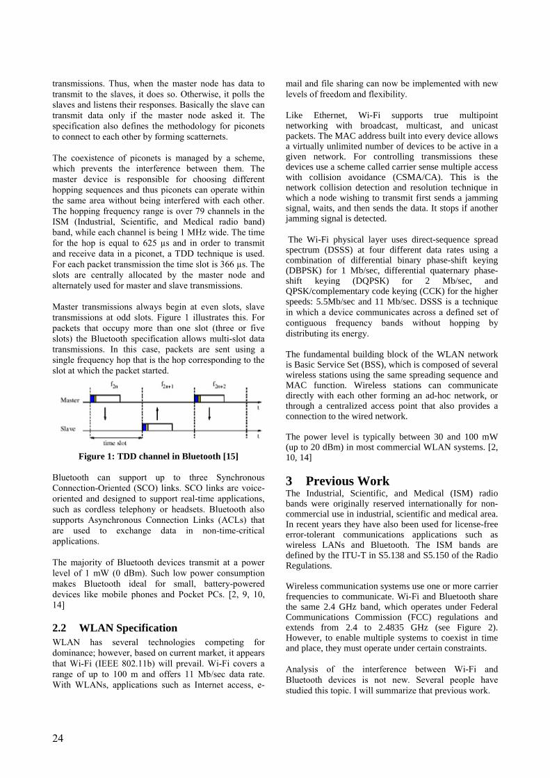
transmissions. Thus, when the master node has data to transmit to the slaves, it does so. Otherwise, it polls the slaves and listens their responses. Basically the slave can transmit data only if the master node asked it. The specification also defines the methodology for piconets to connect to each other by forming scatternets. The coexistence of piconets is managed by a scheme, which prevents the interference between them. The master device is responsible for choosing different hopping sequences and thus piconets can operate within the same area without being interfered with each other. The hopping frequency range is over 79 channels in the ISM (Industrial, Scientific, and Medical radio band) band, while each channel is being 1 MHz wide. The time for the hop is equal to 625 µs and in order to transmit and receive data in a piconet, a TDD technique is used. For each packet transmission the time slot is 366 µs. The slots are centrally allocated by the master node and alternately used for master and slave transmissions. Master transmissions always begin at even slots, slave transmissions at odd slots. Figure 1 illustrates this. For packets that occupy more than one slot (three or five slots) the Bluetooth specification allows multi-slot data transmissions. In this case, packets are sent using a single frequency hop that is the hop corresponding to the slot at which the packet started.
Figure 1: TDD channel in Bluetooth [15] Bluetooth can support up to three Synchronous Connection-Oriented (SCO) links. SCO links are voice-oriented and designed to support real-time applications, such as cordless telephony or headsets. Bluetooth also supports Asynchronous Connection Links (ACLs) that are used to exchange data in non-time-critical applications. The majority of Bluetooth devices transmit at a power level of 1 mW (0 dBm). Such low power consumption makes Bluetooth ideal for small, battery-powered devices like mobile phones and Pocket PCs. [2, 9, 10, 14]
2.2 WLAN Specification WLAN has several technologies competing for dominance; however, based on current market, it appears that Wi-Fi (IEEE 802.11b) will prevail. Wi-Fi covers a range of up to 100 m and offers 11 Mb/sec data rate. With WLANs, applications such as Internet access, e-
mail and file sharing can now be implemented with new levels of freedom and flexibility. Like Ethernet, Wi-Fi supports true multipoint networking with broadcast, multicast, and unicast packets. The MAC address built into every device allows a virtually unlimited number of devices to be active in a given network. For controlling transmissions these devices use a scheme called carrier sense multiple access with collision avoidance (CSMA/CA). This is the network collision detection and resolution technique in which a node wishing to transmit first sends a jamming signal, waits, and then sends the data. It stops if another jamming signal is detected. The Wi-Fi physical layer uses direct-sequence spread spectrum (DSSS) at four different data rates using a combination of differential binary phase-shift keying (DBPSK) for 1 Mb/sec, differential quaternary phase-shift keying (DQPSK) for 2 Mb/sec, and QPSK/complementary code keying (CCK) for the higher speeds: 5.5Mb/sec and 11 Mb/sec. DSSS is a technique in which a device communicates across a defined set of contiguous frequency bands without hopping by distributing its energy. The fundamental building block of the WLAN network is Basic Service Set (BSS), which is composed of several wireless stations using the same spreading sequence and MAC function. Wireless stations can communicate directly with each other forming an ad-hoc network, or through a centralized access point that also provides a connection to the wired network. The power level is typically between 30 and 100 mW (up to 20 dBm) in most commercial WLAN systems. [2, 10, 14] 3 Previous Work The Industrial, Scientific, and Medical (ISM) radio bands were originally reserved internationally for non-commercial use in industrial, scientific and medical area. In recent years they have also been used for license-free error-tolerant communications applications such as wireless LANs and Bluetooth. The ISM bands are defined by the ITU-T in S5.138 and S5.150 of the Radio Regulations. Wireless communication systems use one or more carrier frequencies to communicate. Wi-Fi and Bluetooth share the same 2.4 GHz band, which operates under Federal Communications Commission (FCC) regulations and extends from 2.4 to 2.4835 GHz (see Figure 2). However, to enable multiple systems to coexist in time and place, they must operate under certain constraints. Analysis of the interference between Wi-Fi and Bluetooth devices is not new. Several people have studied this topic. I will summarize that previous work.

25
Figure 2: ISM radio band
Early attempts to define the mutual interference effects have been based on simple geometric models of Bluetooth deployment. The research focused on the problem of calculating the probability of an overlap, in both time and frequency, of a continuous sequence of Bluetooth packets and an IEEE 802.11b direct sequence 11-Mb/sec packet was done by Greg Ennis in September 1998 [3]. In this paper the issue of relative power levels between the desired 802.11 packet and the interfering Bluetooth packet were not considered. The paper also assumed that the Bluetooth node is transmitting over the entire 625 µsec slot. And the fact that the time offset between the beginning of the WLAN packet and the first Bluetooth packet is a random variable was not fully taken into account. Mr. Zyren in his paper "Extension of Bluetooth and 802.11 Direct Sequence Model" in November 1998 made several refinements on the previous assumptions [4]. Jim Zyren kept the basic model that had been introduced by Ennis but made some modifications to that model. These efforts, however, did not examine in detail the ramifications of the physical layer such as hopping, spectral masks, and filter selectivity, nor did they discuss implementation issues. In addition, the geometries studied did not necessarily correspond to practical usage models. In June 1999 Mr. Zyren presented a more complete paper at the Bluetooth �99 conference entitled Reliability of IEEE 802.11 Hi Rate DSSS WLANs in a High Density Bluetooth Environment [5]. In September he presented a summary of that paper at an IEEE 802.15 meeting. In this paper Mr. Zyren included some more detailed Physical layer assumptions. In their article N. Golmie and F. Mouveraux modeled the physical and medium access controller (MAC) behaviors [7]. Such modeling is necessary to predict the performance accurately. The white paper, �Wi-Fi (802.11b) and Bluetooth Simultaneous Operation: Characterizing the Problem�, received wide acceptance by the industry as the definitive treatment of this issue. [3, 4, 5, 6, 7, 16] For the basis of this paper, it is important to establish that Wi-Fi performance generally suffers more from
Bluetooth activity than vice versa. The reasons for this are explained in the white paper mentioned above, but in summary, there are two main reasons:
• First, the 802.11b MAC is an adaptation of the wired Ethernet MAC, and therefore uses carrier-sense before transmission (�listen before talk�). Unlike Ethernet, the Wi-Fi MAC cannot detect collision, so for Wi-Fi it is required that every received packet is acknowledged by an acknowledgement (ACK). If a station or access point transmitted a packet but does not receive an ACK from its target recipient, it assumes that a collision with another Wi-Fi transmission has occurred. To avoid additional Wi-Fi collisions, the station pauses for a few microseconds and then transmits again. By using this mechanism among others, wired and wireless Ethernet work very efficiently in a homogenous environment. But in an unpredictable and highly interfering Bluetooth/Wi-Fi environment, this mechanism results in repeated error correction without corresponding interference improvement. Ultimately, this will lead to a reduced Wi-Fi throughput.
• Second, the Wi-Fi protocol is highly susceptible
to collision with Bluetooth. Roughly, the probability that a standard Wi-Fi 1500 byte transmission will collide with a simultaneous Bluetooth transmission is 55%. This results from the fact that Wi-Fi requires approximately 1 to 1.5 milliseconds to receive a 1500 byte packet at 11 Mbps.
4 Overview of Coexistence
Mechanisms Coexistence of 802.11 and Bluetooth occurs when the two systems operate in a shared environment without significantly impacting the performance of each other. According to the IEEE 802.15 Working Group, when the distance between the interfering devices is less than 2 meters, the interference between 802.11 and Bluetooth causes a severe degradation of the systems� throughput; a slightly less significant degradation is observed when the distance ranges from 2 to 4 meters. In order to devote to the development of the coexistence mechanisms and mitigate such an effect, the IEEE 802.15 Working Group has created the Task Group 2 (TG2). The Bluetooth specification was designed to make the Bluetooth devices very robust to interference from other devices that operate in the ISM band. The Bluetooth 1.1 specification does not include any techniques to avoid interference in the ISM band or to protect another system from interference with Bluetooth. However, it is flexible and allows the development of coexistence techniques.

26
Bluetooth version 1.2 includes techniques for coexistence with Adaptive Frequency Hopping (AFH) (see Section 4.2). There are two classes of coexistence mechanisms that have been defined: collaborative and non-collaborative techniques. It is possible to implement collaborative techniques when interfering devices are co-located in the same terminal. With collaborative techniques the Bluetooth network and WLAN can exchange information to reduce the mutual interference. With non-collaborative techniques there is no way to exchange information between the two network systems and they operate independently. The coexistence model will quantify the effect of mutual interference of WLAN and Bluetooth networks on each other while the coexistence mechanism will facilitate the coexistence of WLAN and Bluetooth devices. When a Bluetooth device and a Wi-Fi device operate in the same area, a single 22 MHz-wide Wi-Fi channel occupies the same frequency space as 22 of the 79 Bluetooth channels, which are 1 MHz wide. When a Bluetooth device starts transmission on a frequency that lies within the frequency space occupied by a simultaneous Wi-Fi transmission, some level of interference can happen, depending on the strength of signals. This performance degradation can occur in the following cases: The most pronounced negative effect occurs when a Bluetooth device is co-located with a Wi-Fi device, for example in a laptop PC with both Wi-Fi and Bluetooth functionality. 1) The effects are slightly less severe when the transmitting Bluetooth device is located within the same piconet as a collocated Bluetooth and typically within 1 meter from the collocated Bluetooth/Wi-Fi device. 2) The least negative effects occur when the interfering Bluetooth is outside the collocated Bluetooth�s piconet and more than 2 meters from the collocated device. 3) Additional factors can either improve or worsen the negative effects mentioned above. One of these factors is in-band and out-of-band communication of the two protocols. Table 1 below gives an overview of the different interference scenarios.
Table 1: The interference cases for Bluetooth and 802.11b [14]
Bluetooth Tx Bluetooth Rx In-band Out-of-
band In-band Out-
of-band
Tx No conflict
No conflict Strong Interf.
Moderate Interf.
802.11b
Rx Strong Interf.
Moderate Interf.
Strong Interf.
Moderate Interf.
When a Bluetooth device encounters interference on a channel, it waits for the next channel and tries again. Using this method it can attempt to avoid interference from a Wi-Fi network. When using Asynchronous Connection-Less (ACL) links, the result will be degradation in the data throughput. When transmitting time-sensitive information such as voice on Synchronous Connection Oriented (SCO) links, packets can be lost because these links do not utilize Automatic Repeat Request (ARQ). Wi-Fi deals with interference like Ethernet does. If a transmission fails it assumes that a collision has occurred and also an ARQ is issued. In addition, many installations of 802.11b offer the optional automatic data rate modification feature, which allows the data rate to fall back from 11 Mbps to 5.5 Mbps, 2 Mbps, or even 1 Mbps for minimizing Bit Error Rate (BER) due to poor signal-to-noise ratio (SNR). Using this scenario, if a Wi-Fi device encounters interference from a Bluetooth transmission and reduces its transmission rate, it will then spend more time than before transmitting a packet on a frequency available to Bluetooth. Data is not lost, but the data throughput rate may slow down to an intolerable level. In the following sections the detailed description of collaborative and non-collaborative coexistence mechanisms is given. [10, 14, 15, 16]
4.1 Collaborative Coexistence Mechanisms Collaborative coexistence mechanisms allow Bluetooth and WLAN to communicate and cooperate with minimized mutual interference. The collaborative techniques require that a Wi-Fi device and a Bluetooth device are collocated (e.g. located in the same laptop). The following scheduling schemes are examples of collaborative coexistence mechanisms: META (MAC Enhanced Temporal Algorithm), and the TDMA (Time Division Multiple Access) scheme. These mechanisms have been proposed to mitigate the interference between a 802.15 device and a 802.11

27
device that are co-located in the same terminal. META mechanisms involve the use of a centralized controller that monitors the Bluetooth and the 802.11 traffic and allows the exchange of information between the two radio systems. The controller works at the MAC layer and avoids interference between the two collocated devices by precise timing of packet traffic. 802.15 voice traffic has priority over WLAN packets; if Bluetooth traffic is not time-critical WLAN traffic is transmitted first. When there is voice traffic pending, WLAN packets are queued. TDMA (Time Division Multiple Access) techniques allow Wi-Fi and Bluetooth to alternate transmissions. In TDMA mode, the 802.11b beacon-to-beacon interval is subdivided into two subintervals: one subinterval for 802.11b and other subinterval for Bluetooth. Because each radio has its own subinterval both systems will operate properly. Figure 3 bellow illustrates this method.
Figure 3: TDMA technique [1]
This technique requires an additional feature to control when the Bluetooth Master transmits. The mode to be used is chosen under the command of the Access Point (AP) management software. [1, 8, 10, 14, 15, 16]
4.2 Non-collaborative Coexistence Mechanisms
In a non-collaborative coexistence mechanism there is no possibility for Bluetooth and WLAN to communicate. One of the non-collaborative mechanisms is Adaptive Packet Selection and Scheduling. Adaptive packet Selection and Scheduling is a Bluetooth Media Access Control (MAC)-level enhancement that utilizes a frequency usage table to store statistics on channels encountering interference. By carefully scheduling the packet transmission so that the Bluetooth devices transmit only during those hops that are outside the WLAN frequencies, we could minimize the interference with the WLAN systems and at the same time increase the throughput of the Bluetooth systems. In addition,
Bluetooth systems define various packet types depending on various configurations such as packet length and degree of error protection used. By selecting the best packet type according to the channel conditions of the upcoming frequency hop, better data throughput and network performance can be obtained. Another example of a non-collaborative coexistence mechanism is the Adaptive Frequency Hopping (AFH) technique. Adaptive frequency hopping is a method by which the available channels are used intelligently to decrease the likelihood of a packet loss by classifying channels and altering the regular hopping sequence to avoid channels with the most interference. Figure 4 illustrates the AFH method.
Figure 4: AFH method [1]
The AFH mechanism for Bluetooth can be divided into four main steps: 1) Channel Classification. During this phase the classification of frequency channels is made. Channels can be defined either as �good� or �bad� according to the level of interference on that channel. 2) Link Management (LM). The primary role of the LM component is to coordinate and distribute the AFH information to all Bluetooth nodes in the network. 3) Hop Sequence Modification. In order for the Bluetooth node to avoid bad channels the number of hopping channels within the sequence have to be selectively reduced. 4) Channel Maintenance. Finally, due to the unpredictability of the wireless medium it is important to periodically re-evaluate the quality of the channels. Having established the good frequency channels, each Bluetooth node modifies its frequency hopping sequence through the Sequence Modification method, thereby avoiding the interference limited bad channels. According to this scheme, frequency channels are classified as �good� or �bad� and hops are adaptively selected from the number of �good� channels. There are two methods that adaptively hopping uses in practice. In the first method called Mode L �bad� channels are
Bluetooth Interval
802.11 Beacon

28
classified and further removed from the hopping sequence. In the second method (Mode H) some grouping of the �bad� and �good� channels is made so that the hopping sequence may intelligently schedule the use of the �bad� channels and maximize the use of the �good� channels. The AFH method allows devices to perform well under a variety of interference scenarios. However, since the majority of the current Bluetooth implementations perform the hop selection in hardware, this technique would imply a new release of Bluetooth devices. The last non-collaborative mechanism to be presented is Transmit Power Control / Rate Scaling. Power control may be used if a transmit power control mechanism is implemented. This method is effective if the IEEE 802.11b and the Bluetooth devices are designed to limit there transmit powers near the threshold to obtain the required performance. All IEEE 802.11b devices currently support multiple transmit rates, i.e. 1 Mb/s, 2 Mb/s, 5.5 Mb/s and 11Mb/s. As a result, all IEEE 802.11b devices currently implement a rate shifting algorithm. By analyzing the signal-to-noise ratio and the error rate the systems determine which rate should be used. The maximum rate is always desired. The rate is shifted down when packets cannot be successfully decoded at current rate. The rate control algorithm of IEEE 802.11b devices can be extended to incorporate the highest mandatory rate at lower transmit powers. The rate shift algorithm would shift to the highest possible rate with lower transmit power, when it is possible. [1, 8, 10, 14, 15, 16]
4.3 Overlap Avoidance Schemas In [15], two other coexistence mechanisms so-called OLA (OverLap Avoidance) schemes that are based on simple traffic scheduling techniques were proposed. They can either operate as collaborative or non-collaborative coexistence mechanisms and are able to reduce interference both in the case of collocated and non-collocated devices. One of the mechanisms is designed to be used with IEEE 802.11 in the presence of a Bluetooth voice link, and the second mechanism is designed to be used in a Bluetooth system in case of a data link. These two mechanisms are jointly applied when both voice and data links are active over the Bluetooth channel. They are based on the assumption that both the 802.11 and Bluetooth devices can detect interference. This assumption is true in a collaborative case, where Bluetooth and 802.11 can directly exchange information related to their traffic transmissions. In a non-collaborative case, this information can be received by checking the channel and assessing the received signal strength and the packet loss rate.
The OLA coexisting mechanisms do not require a centralized controller since they do not perform time scheduling of the 802.11 and Bluetooth packet traffic. The proposed algorithms have minor impact on the 802.11 standard and Bluetooth specification. Thus the proposed algorithms have the following advantages: 1) They do not need a centralized traffic controller. 2) They can be implemented either in collaborative or non-collaborative mode. 3) They are able to mitigate interference between co-located and non-collocated Bluetooth and IEEE 802.11 devices. 4) They have minor impact on the IEEE 802.11 standard and on the Bluetooth specification. The following sections describe the OLA method in more details. [15] 4.3.1 V-OLA Mechanism OLA mechanisms use simple traffic scheduling techniques at the MAC layer. The first algorithm, denoted by V-OLA (Voice-OverLap Avoidance), is used in the case of Bluetooth voice links. By performing a proper scheduling of the traffic transmissions at the WLAN stations this scheme avoids overlap in time between the Bluetooth voice traffic and the 802.11 data packets. In a Bluetooth network, each SCO link occupies TDD channel slots according to a deterministic pattern. Thus, the 802.11 station should start transmitting data when the Bluetooth channel is idle and calculate the length of the WLAN packet so that it fits between two successive Bluetooth transmissions. [15] 4.3.2 D-OLA Mechanism The second algorithm, denoted by D-OLA (Data-OverLap Avoidance), is suitable for Bluetooth data links. The length of the Bluetooth packets can be equal to one, three or five time slots. In the case of multi-slot transmissions, packets are sent by using a single frequency hop, which is the hop corresponding to the slot at which the packet has been started (see Section 2.1). The main idea of the D-OLA algorithm is to use the variety of packet lengths to avoid overlap in frequency between 802.11 and Bluetooth transmissions. Within each interfering piconet, the D-OLA algorithm dictates the Bluetooth master device to schedule data packets with proper duration (i.e., one, three or five slots). This is needed to skip the frequency locations of the hopping

29
sequence that are expected to be dropped on the 802.11 band. It is assumed that the Bluetooth master devices are aware of which frequency channels are occupied by the interfering 802.11 stations. Since a 802.11 system does not typically move from its 22 MHz frequency band in a non-collaborative setting, a Bluetooth device can identify the frequency channels that are occupied by the WLAN by using any of the following methods: 1) The Bluetooth device can identify which channels are occupied based on the observed packet loss. 2) The Bluetooth device checks the received signal strength (RSSI) across the radio environment before it starts operating. 3) The Bluetooth device transmits �test� packets across the frequency spectrum, observes the packet loss rate over the channels and discovers the band used by an interfering system. Let us focus on the TDD channel of one piconet. Lets assume that a master transmission always begins in even slots, while slaves can start transmitting in odd slots only. For the simplicity it is also assumed that default data packets are one slot long. Let us denote by fm the frequency location of the hopping sequence at the generic time slot m and let the current time slot be equal to 2n. Thus f2n and f2n+1 correspond to a master and a slave transmission, respectively. According to the D-OLA algorithm, if enough data is buffered at the master slot, it schedules a multi-slot packet instead of a single-slot packet. In this way, frequency hop f2n+1 is skipped; for instance, if a 3-slot packet is sent, the next slave transmission will use f2n+3. Next, assume that among the frequency locations following f2n, f2n+2 hops on the 802.11 band. Frequency location f2n+2 corresponds to a master transmission. In this case, at time slot 2n the master asks the slave that will transmit in the next slot, to send a multi-slot packet so that f2n+2 is skipped. If the slave has enough data to send, let us say, a 3-slot packet, the slave transmission extends from slot 2n+1 to slot 2n+3 by using frequency f2n+1 only. The next slot allocated for the master transmission will therefore hop on frequency location f2n+4. A similar mechanism is applied when default data transmissions use 3-slot or 5-slot packets. The scheduling algorithm could also let the master (slave) refrain from transmitting in the time slot corresponding to a frequency that hops on the 802.11 band whenever there is not enough data in the buffer at the master (slave) to send a multi-slot packet. In this case, the collision probability is reduced more but the Bluetooth throughput decreases as well. [15]
5 Conclusion In this paper the problem of coexistence between IEEE 802.11 WLANs and IEEE 802.15 WPANs was addressed. Coexistence and simultaneous operation between Wi-Fi and Bluetooth technologies is a desirable goal. Both technologies are expected to grow rapidly over the next few years for offering new levels of portability. The development of 802.11b and Bluetooth coexistence mechanisms is not a new research topic. The aim of this paper is to summarize the state of the art of these mechanisms. References
[1] IEEE 802.15 WPAN� Task Group 2 (TG2), http://www.ieee802.org/15/pub/TG2-Coexistence-Mechanisms.html (accessed 18.04.2004)
[2] HP invent: Wi-Fi� and Bluetooth� - Interference Issues, January 2002
[3] G Ennis, "Impact of Bluetooth on 802.11 Direct Sequence," IEEE 802.11-98/319, September 1998.
[4] J Zyren, "Extension of Bluetooth and 802.11 Direct Sequence Model," IEEE 802.11-98/378, November 1998.
[5] J. Zyren, Reliability of IEEE 802.11 Hi Rate DSSS WLANs in a High Density Bluetooth Environment. Bluetooth �99, June 8 1999. Submission Page 11 Steve Shellhammer, Symbol Technologies May 2000 IEEE P802.15-00/133r0
[6] J. Zyren, Reliability of IEEE 802.11 WLANs in Presence of Bluetooth Radios. IEEE 802.15-99/073r0, September 1999.
[7] N Golmie and F Mouveraux, "WPAN Coexistence Performance Evaluation: MAC Simulation Environment and Preliminary Results," IEEE 802.15-00/066r0, March 2000.
[8] Carla F. Chiasserini, Ramesh R. Rao: A Comparison between Collaborative and Non-Collaborative Coexistence Mechanisms for Interference Mitigation in ISM Bands, August 2002
[9] Bluetooth Core Specification, http://www.bluetooth.com (accessed 16.04.2004)
[10] Matthew B. Shoemake: Wi-Fi (IEEE 802.11b) and Bluetooth. Coexistence Issues and Solutions for the 2.4 GHz ISM Band, Texas Instruments, February 2001
[11] IEEE P802.15 Working Group for Wireless Personal Area Networks (WPANs): Overview of coexistence mechanisms, 15 June 2001

30
[12] Jagdip Singh Mander, Dimitri Reading-Picopoulos and Chris Todd: Evaluating the Adaptive Frequency Hopping Mechanism to Enable Bluetooth � WLAN Coexistence, University College London, September 2003
[13] Tim Godfrey: 802.11 and Bluetooth Coexistence Techniques, November 6, 2002
[14] Mobilian Corporation: Wi-Fi� (802.11b) and Bluetooth�: An Examination of Coexistence Approaches, 2001
[15] Carla F. Chiasserini and Ramesh R. Rao: Coexistence Mechanisms for Interference Mitigation between IEEE 802.11 WLANs and Bluetooth, IEEE INFOCOM 2002
[16] Jim Lansford, Adrian Stephensm, Ron Nevo: Wi-Fi (802.11b) and Bluetooth: Enabling Coexistance, Mobilian Corporation, September/October 2001

31
Fault tolerance in IP based networks
Heikki Almay Nokia Networks
[email protected] Abstract Building fault tolerant IP based networks is a key challenge for public network operators moving from TDM to a packet based service machinery. Services such as conversational voice and telephony signaling require faster failover times than traditional TCP based applications. Resilience can be implemented on different protocol layers and in both the wide area as well as the local area networks. In recent years fast failover mechanisms have been developed. These allow sub-second recovery from most types of link and node failures, but interworking issues between the protocols and the network domains in some cases still reduce the end-to-end performance. 1 Introduction
1.1 Background IP has been developed with survivability and reliability in mind [1], [2]. Inbuilt fault tolerance is also one of the key advantages when IP networks are compared to traditional TDM networks. There is a strong case for IP as it is a connectionless technology that allows building networks that automatically discover alternative routes, perform topology changes and continue services in case of node or interface failures. In traditional connection oriented TDM networks management intervention or the provisioning of alternative links that in most cases duplicate the required transport capacity is required for restoring service after failures. For most applications fault tolerance in IP networks can be considered as a solved issue. Web browsing, file transfers, e-mail and other applications built on top of TCP are affected by faults in the IP network (retransmissions because of lost packets, reduced bandwidth etc.) but generally the services do survive. Even though resilience requirements have increased the survivability provided by dynamic routing is still a valuable feature. Disaster recovery, which is expensive and laborious to implement for TDM networks is inbuilt in IP technology. The increasing use of IP networks as the uniform platform for mission critical business applications ranging from the stock market to process control in the factories has gradually tightened the resilience requirements, and led to the introduction of various resilience schemes (discussed later in this paper) and more careful planning of IP networks. Currently IP based networks are becoming the technology of choice for telecom type of applications. Many of these have strict real time requirements and low tolerance for delay variation and packet loss. The most demanding services include conversational voice
services, two-way video, signaling for telephony and emulation of TDM-links. These services are typically using UDP instead of TCP, as they can not adapt to greatly reduced bandwidth or service cuts that last tens of seconds. For these new services resilience requirements in IP based networks have to be redefined.
1.2 Scope of this paper This paper discusses technologies and practices for building fault tolerance in IP based networks. This includes both building fault tolerant IP networks and connecting the service nodes to the network in a fault tolerant way. Generally the first issue is rather narrow and well understood in theory [3], [4], [5] while the second issue is broad and generally only discussed from the perspective of standard commercial servers. For both the fault tolerant IP based network as well as the connectivity of service nodes there is a gap between theory and practice. Theories typically have difficulties in covering all real life phenomena � especially the interworking of different protocol layers in complex environments. The focus of this paper is on a telecom type of environment where chargeable user data, real time services and signaling traffic originating from appliances and servers set the requirements for fault tolerance. Instead of rushing for network element level requirements derived from the tolerances of the listed services the paper discusses the operation of available resilience mechanisms in real network topologies and focuses on some of the more challenging failure cases that easily lead to service outages. In telecom networks most of the service nodes are concentrated to a limited number of sites. When considering IP transport and fault tolerance the network operator has to consider two domains, the connectivity on the sites and the connectivity between the sites. For many datacom services (e.g. corporate WAN and Internet access) also the access network is of importance.

32
This area is not covered in this paper. The same applies to the nontrivial issues of fault tolerant interconnections to other networks and general Internet connectivity. Fault tolerance of IP based services is not solely relying on resilience mechanisms of IP and the underlying link layer and physical layer protocols. In many cases it can also be provided on the server side (e.g. load balancers directing traffic only to servers that reply to keep-alive messages or using fault tolerant TCP/IP servers [6]). For some services resilience can also be configured in the client (e.g. several alternative DNS servers). While these solutions are very useful they are beyond the scope of this paper and discussed only as far as there are known consequences to the IP layer. Another issue not discussed is how to build fault tolerant network elements - how to construct dual power supplies and routing engines is beyond the scope of this paper. However, recommendations on where to use more robust network elements is given and some clustering techniques are handled as they may apply as well inside a network element as between several elements. 2 Reference network
2.1 Network architecture The reference architecture discussed in this paper is shown in Figure 1. It focuses on the network operator sites hosting the service machinery and the backbone connecting the sites to each other. The figure is derived from a 3GPP Rel.4 compliant mobile operator environment where the service elements would include gateways (SGSN, GGSN, media gateway) and servers (MSC Server, HLR etc.). The same architecture applies well to the wireline environment with DSL subscriber management systems and a next generation network with softswitches and voice gateways.
site site
LAN + IPLAN + IP
Backbone: IP, IP/MPLS, ATM, SDH, DWDM…
site
LAN + IP Figure 1: Reference network
The discussion is to a large extent applicable to the regional network and sites hosting radio network controllers, base station controllers or large wireline access concentrators. In the access network where bit rates are orders of magnitude smaller and typical resilience requirements are less strict than in the core many of the discussed methods for achieving fault tolerance are considered too costly.
Note that the discussion in this paper is limited to one administrative domain. So no peering connections are shown in Figure 1. Figure 1 also excludes server sites (web hosting/data centers/MMSC etc.) as the fault tolerance of these systems is mostly related to issues higher up in the protocol stack.
2.2 Used technologies The sites of the reference network are built with LAN, mostly Fast Ethernet (FE) and Gigabit Ethernet (GE). Connectivity is provided using Ethernet switching and IP routing. In a telecom environment customer traffic entering the site from the access network will be carried back and forth between several elements and in many cases sent back to the access network to another subscriber. The wide area network may consist of an IP/MPLS backbone. This is the technology of choice for new packet-based networks. As an alternative existing ATM backbones can be used. In small networks it is also possible to implement the backbone using point-to-point connections between the edge routes on each site. The physical layer in the wide area network between operator sites is almost always implemented using SDH. While alternative technologies are slowly becoming available, the renewal of the transmission network is slow and much more affected by the installed base than other parts of the network. In Figure 1 also DWDM is indicated as a potential backbone technology. Basically the existence of a DWDM system in the operator network means that bandwidth as such is not a constraint. Typically it is used for being able to run the packet network in parallel with the existing TDM network. A reader familiar with the typical MPLS implementation may be confused with Figure 1 as a normal MPLS environment would consist of customer edge (CE) devices, provider edge (PE) devices and the MPLS core (P) devices. In Figure 1 LAN switching, CE and PE functionality are included in the site switch/router. This is done for simplifying the network structure and for cost saving. Test cases and practical discussions later on refer to this type of setup. The difference of the chosen solution to an architecture where switching, CE and PE functionality is split is not very significant. 3 Fault tolerance
3.1 Definitions and theory While it is easy to require that services should be available without breaks and that networks should recover from failure situations a more careful definition of the characteristics is needed for being able to address

33
the technical implementations of service continuity or network survivability. Below some definitions of the most commonly used terms are given.
Failover indicates an operational mode in which the functions of a system-critical component (such as a processor, a network element, or a database) are assumed by secondary system components when the primary equipment becomes unavailable through either failure or scheduled down time. The capacity for automatic failover indicates that normal functions can be maintained despite the inevitable interruptions caused by problems with equipment. Source: http://www.eisst.com/resources/glossary
Failover indicates an operational mode in which the functions of a system-critical component (such as a processor, a network element, or a database) are assumed by secondary system components when the primary equipment becomes unavailable through either failure or scheduled down time. The capacity for automatic failover indicates that normal functions can be maintained despite the inevitable interruptions caused by problems with equipment. Source: http://www.eisst.com/resources/glossary
Reliability: The probability of an item operating for a given amount of time without failure. More generally, reliability is the capability of parts, components, equipment, products and systems to perform their required functions for desired periods of time without failure, in specified environments and with a desired confidence.
Sou rce: h t tp :/ / w w w .w eibu ll.com /k n ow led ge/ rel_g lo ssar y.h t m
Fault Tolerant: A method of making a network system or a computer resistant to transmission errors, software errors, hardware problems or power failures.
Resilient: 1 able to recoil or spring back into shape after bending, stretching, or being compressed. 2 (of a person) able to withstand or recover quickly from difficult conditions.
Source: Compact Oxford English Dictionary
So u rce: h t tp :/ / w w w .cek no w how .com / g lossary/ In d ex.cfm ?Glo ss= 4 8 5 &DivI D= 5 &term =
Figure 2: Definitions
Reading the definitions above it is easy to state that for achieving fault tolerant systems reliable and resilient components with fast failover capabilities need to be in place (i.e. its parts should break seldom and the system should continue working even if one part happens to break). Note that failover occurs between elements that operate in parallel. So resilience requires spare capacity. The capacity can be provided on a 1+1 basis so that a protection resource similar to the used one is reserved for the case of failure. In the more advanced 1:1 (or N:1) schemes one resource with less important functions is taken into use for protection in case any of the protected resources fails. When a node or link failure occurs the affected network elements will initially need some time for detecting the error. On the physical layer the detection is a based on monitoring the link pulse or transmission alarms. These methods allow failure detection within a few milliseconds. The problem with physical layer failure detection is that only the transmission link is monitored. For a TDM link (e.g. E1) this may include a chain of tens of SDH nodes, but in a LAN environment only the link to the next switch is covered. If on the other side of that switch all uplinks are broken, this will not be discovered before upper protocol layers react. These upper layer protocols (e.g. OSPF and PNNI) exchange messages with their peers in the neighboring network elements. A router discusses with the next router and an ATM switch with the next ATM switch etc. without considering the implementation of the underlying transport. If the connection to the neighbor is broken, the network node will not receive any answers to its messages and after some (typically three or four) tries the connection to the neighbor is considered as lost. Once a failure has been detected the mechanisms used for recovery also take some time. In a routed
environment a topology change easily leads to routing loops. The convergence time is the period needed to share the new topology information to all routers and for them to calculate the optimal paths.
3.2 Resilience requirements The resilience requirements are derived from the behavior of the applications used in the network, the importance of traffic and the number of users affected by a potential outage. Below some examples of the different types of requirements are discussed. Voice is one of the key user applications setting stringent failover requirements to the network. A service cut of several seconds leads to the call being dropped because of user frustration even though the service could be recovered. In addition to the actual voice packets a public voice service carried over IP includes signaling. Between the public network elements signaling (e.g. SIP-T) is carried using Stream Control Transmission Protocol (SCTP [11]) instead of TCP. One of the key features of SCTP is multi-homing. It allows SCTP to use several IP addresses on the service nodes and assumes that the traffic from and to the different addresses is carried on the alternative paths. Depending on the implementation and parameters the time for SCTP to switch over to the secondary path varies, but often sub-second failover times are required. If lower protocol levels implement resilience schemes they need to be faster than SCTP in order to be effective. 4 WAN resilience mechanisms
4.1 SDH resilience SDH is a robust technology that includes a number of resilience schemes including path protection (end-to-end), schemes for unidirectional and bi-directional ring topologies and multiplex section protection (covering the link between two SDH nodes and potentially repeaters between them). Link quality is constantly monitored and failover times are less than 50ms. In a TDM and leased line business environment it is a standard practice to use SDH for resilience in the WAN. As SDH was originally developed for a TDM environment and heavily focused on ring structures the fault tolerance is typically implemented by essentially reserving twice the needed capacity. This combined with the fact that the virtual container types available in traditional SDH networks do not support the bit rates commonly used in data networking leads to a significant waste of bandwidth. This increases costs. A Fast Ethernet (100 Mbit/s) link is carried across a traditional SDH network using a VC-4 container (140 Mbit/s). So a maximum achievable usage of the container is 71%. In

34
case a second VC-4 is reserved across the network the needed capacity is three times the theoretically achievable bit rate. The actual data rate is in most cases significantly less as the ingress link is hardly ever 100% loaded. In recent years SDH has been developed to better suit to the datacom environment. Virtual concatenation allows the mapping of the data interfaces to the SDH payload in fragments, (e.g. 10 Mbit/s could be mapped as 5 x VC-12 = 5 x 2Mbit/s). In addition to the more efficient mapping schemes the Next Generation SDH equipment also support Ethernet and ATM interfaces. They also implement the Link Capacity Adjustment Scheme (LCAS, ITU-T G.7042), which allows the change of virtually concatenated capacity in increments of its fragments. So the above 10 Mbit/s link can be e.g. increased to 12 Mbit/s if the actual traffic increases. In addition to efficient provisioning LCAS can also be used for providing resilience as shown in Figure 3 below where the 10 Mbit/s total capacity is split between two routes working in parallel.
large site small siteSDHSDH SDHSDH
Total VC12-5v (10 Mbit/s) Route with 3 x 2Mbit/s
Route with 2 x 2Mbit/s
Figure 3: Fault tolerance using the SDH Link
Capacity Adjustment Scheme
Note that in the above example the capacity use in the SDH network is very efficient. In the �Next Generation SDH� the efficiency problems related to carrying data traffic over traditional SDH networks are solved. More information on �Next Generation SDH� features can be found e.g. in [7].
4.2 Link layer resilience In the wide area network between operator sites three major link layer protocol suites are used. These are PPP, ATM and MPLS. MPLS is often called layer 2.5 as it includes lots of network layer functionality. 4.2.1 PPP When IP is carried over TDM links (e.g. IP over SDH) Point-to-point protocol (PPP, RFC 1661, [24]) is used. As the name indicates, the protocol is by nature point-to-point. It does not consider resilience. However, multiple PPP links can be bonded together using Multilink PPP (RFC 1990[25]). This technology is commonly used at slow speeds (up to n x E1) circuits to provide channel aggregation. RFC 1990 allows adding and removing links from the Multilink connection. So the technology can to some extent be used for resilience.
4.2.2 ATM While ATM Protection Switching is well defined in ITU-T I.630 [8] it seems that this specification is not widely used in practical networks. Instead, ATM layer resilience is in many cases built using PNNI (Private Network-to-Network Interface or Private Network Node Interface, [9]). It consists of two protocols. One distributes topology information between switches so that paths through the network can be computed. A second protocol is used to establish connections across the ATM network. This protocol is based on the User-Network-Interface (UNI) signaling. It includes e.g. mechanisms for alternate routing for the case of connection setup failure. When a signaled permanent virtual circuit (SPVC) fails, PNNI immediately attempts to reroute the connection. In PNNI the minimum hello-interval is defined to be 0.1 s. So rerouting can be done within seconds. Fast SVC Restoration is an ATM Forum work item. 4.2.3 MPLS In MPLS networks resilience can be implemented using dynamic re-routing, protection switching or fast reroute. The IETF views on MPLS traffic engineering and MPLS based recovery are described in [16] and [26]. Dynamic re-routing works the same way as re-routing in an IP network (typically OSPF or IS-IS is used for routing). As no bandwidth is reserved for backup paths the alternative path has to be computed and signaled upon failure, which will result in some recovery delay. MPLS protection switching predefines the backup path during configuration. The backup path is established in parallel to the primary path with or without bandwidth reservation, depending on the protection service model. Protection switching can be faster than dynamic re-routing as the computation and signaling of a new path is not needed. It requires notification to the ingress node in case of failure. Fast re-route (FRR) is a simplified local implementation of protection switching. It can cover node and link protection. Current implementations indicate 50 ms FRR repair time for link failures. Fast re-route combines the approach of local repair and protection switching. No failure notifications are needed as the recovery is initiated at the point of failure. FRR is widely implemented in MPLS products while protection switching is still in an immature stage.

35
4.3 IP resilience 4.3.1 Traditional IP resilience Basic resilience in IP networks is provided by a mesh topology and dynamic routing protocols that detect network topology changes (e.g. link or node failures) and start using alternative routes for the traffic affected by the failures. Basically this single path routing suffers from two shortcomings [13]. Firstly a single link failure will cause an often time-consuming rerouting of traffic, which is not acceptable for traffic with stringent QoS requirements. Secondly the single path routing tends to lead to congestion in case of dynamic load changes. The capabilities of current router products in case of network topology changed is well documented in various test reports [17]. The current routing protocols were designed with processing power and bandwidth limitations in mind as layer 3 implementations used to be software based and expensive. In real networks link and route flapping, interoperability of different protocol implementations and configurations and other unforeseen phenomena affect the routing convergence. 4.3.2 Local action based on information from
lower layers As already discussed earlier the time needed for rerouting consists of the time needed for failure detection and the consequent actions which may require message exchanges with other network nodes and a route calculation. Layer 3 resilience schemes are rather slow. E.g. in OSPF the minimum hello timer interval is one second. It takes three hello timer intervals to conclude that a router is unavailable. This time could be significantly shortened if information from lower protocol layers was used for determining link unavailability [15]. Fast recovery actions are also possible if they are precalculated. These principles are in use in the MPLS domain and also resemble the Rapid Spanning Tree protocol used in the LAN domain. 4.3.3 Routing enhancements Another approach to improve failover times is to build more resilient routing solutions. Recent enhancements include IP event dampening (ignoring state changes for a period if there are too frequent routing updates), BGP convergence enhancements and incremental shortest path first optimization [19]. These routing improvements combined with more resilient routing equipment provide a practical alternative to the new resilience schemes resulting from link availability information provided by the lower layers.
Load balancing can reduce the impact of congestion and service cuts caused by network topology changes. Load balancing features of the routing protocols (OSPF, IS-IS, BGP etc.) make it possible to do equal cost and in some cases unequal cost load balancing between links. Using load balancing the traffic is distributed to several alternative paths. In theory the network is evenly loaded. In case of link or node loss the traffic to be rerouted consists of relatively small streams to diverse destinations which can be easier absorbed by the alternative links and nodes than the whole traffic to a particular destination as is the often the case in a single path routing environment. The use of link state information available from lower protocol layers for routing decisions has been proposed (e.g. [21]). The approach is very similar to MPLS fast reroute. 5 LAN resilience mechanisms
5.1 LAN design A layer 2 switched domain can be considered as a failure domain [5]. Misconfigured and malfunctioning hosts as well as topology changes and broadcast traffic affect the whole domain. So from resilience point of view the size of the layer 2 switched domains should be kept rather small. In a telecom environment this can be done using VLANs to separate the different logical networks (e.g. signaling, management, user plane). Figure 4 shows a typical resilient LAN configuration. Hosts are connected to the layer 2 switches of the access layer. These switches are connected with two separate uplinks to two layer 3 switches (devices that act both as LAN switches and routers). The layer 3 switches are connected to each other in a resilient manner. They also provide resilient connectivity to the core/backbone network.
layer 2 sw i t ch es- access -
layer 2 & l ayer 3- d ist r ib u t io n -
Co re/ b ack b o n e
HSRP
Figure 4: LAN design
The failover times achieved in the described network depend to a large extent on the protocols and features available in the actual products used.

36
5.2 Resilience and loop avoidance As Ethernet frames do not contain any time-to-live information, loops are fatal in a LAN environment. They quickly lead to a saturation of the affected links. So loop detection is essential for fault tolerance in a LAN. The basic method for loop detection and blocking is the Spanning Tree Protocol (STP). In case of a topology change STP convergence can take up to one minute as the whole LAN topology is mapped. Note that in the above LAN design each of the access switches has two uplinks of which one (dashed) is blocked for avoiding loops. Several enhancements that speed up the operation of STP have been made to the original. Vendor specific features (BackboneFast, UplinkFast, PortFast) introduced methods for faster convergence. These achieve faster operation by utilizing local knowledge of the network topology. PortFast for example relies on the assumption that there are no loops on links that directly connect to hosts. These enhancements and a faster convergence scheme have been standardized as IEEE 802.1w, Rapid Spanning Tree Protocol (RSTP, [22]). While RSTP brings failover times down to sub-second values an additional protocol is needed for optimal operation in an environment where VLANs are widely used. STP and RSTP manage the topology of whole ports. If the network operator would like to provide resilient connections to a host in Figure 4 using two VLANs (and two IP subnets) he will face the problem that with STP or RSTP the root bridge for both VLANs is the same device. Both VLANs will use the same uplink and in case of failure in the uplink (or even worse in the layer 3 switch which happens to be also the root bridge) both VLANs will be unavailable. The problem can be overcome using Multiple Spanning Tree Protocol (MSTP, [23]). MSTP allows spanning trees to be run per VLAN so that the root for the different spanning trees is in different devices. In the above example MSTP allows running the two alternative links over different uplinks. In Figure 4 the dashed uplinks would now become active for part of the VLANs. Another benefit of MSTP is that it allows load balancing on the uplinks. In normal operation this doubles the available bandwidth.
5.3 Link aggregation Link aggregation is another technology adding resilience on the links between LAN switches. Several ports can be bundled to form a single logical channel. All aggregated ports have to be of the same type (in practice Fast Ethernet or Gigabit Ethernet). Link aggregation can be done using either vendor specific protocols (EtherChannel) or the Link Aggregation Control Protocol, which is part of an IEEE 802.3ad.
In case one of the physical links fails, the traffic will be distributed to the surviving links. So the aggregation group stays operational as long as one of the physical links is available. Note that in Figure 4 there are two links between the layer 3 switches. In typical configurations these links are aggregated.
5.4 Resilient router interfaces The protocols described above provide important tools for layer 2 resilience. For most applications and connections this is not enough, as most packets do not stay in the layer 2 domain but need routing. In the above figure the layer 2 & layer 3 distribution switches act as default gateways for the hosts. As a host usually relies on a default gateway for routing, the router interface has to be resilient. This is done using the Virtual Router Redundancy Protocol (VRRP, [12]) or Hot Standby Router Protocol (HSRP, Cisco proprietary [14]) or the new Cisco proprietary Gateway Load Balancing Protocol (GLBP, [20]) that essentially provides clustering of routers. These protocols allow establishing a backup of the default gateway known by the hosts on a second router. In case the primary router faces a problem (e.g. the protected interface goes down or WAN connectivity is lost), the secondary router will notice and start serving the hosts. GLBP works in the same way as HSRP and VRRP, but it allows load sharing between a group of routers. In GLBP the active router is responsible for answering ARP requests for the virtual IP address. Load sharing is achieved by replying to the ARP requests with the different virtual MAC addresses of the routers participating in the GLBP group. Note that in some stackable multilayer LAN switches the above protocols are not needed as the routing instances of the stacked units can provide the backup. 6 Resilient IP connectivity for
service nodes and gateways
6.1 Types of service nodes and gateways Typically a service node is a server running unix or Windows and the service in question. Gateways can also be servers, but in many applications (e.g. GGSN, BRAS) router platforms are used. For voice applications platforms derived from the TDM or ATM environment are commonly used. The different types of equipment connect to the IP network using different resilience

37
schemes. In cases where a traffic flow traverses several different types of service elements in sequence careful design is needed for ensuring fault tolerance between the different types of platforms.
6.2 Nodes with duplicated LAN interfaces Some hosts can be equipped with duplicate LAN interfaces so that resilience is provided on the link layer. A typical configuration is shown in Figure 5.
LAN resilience (layer 1-2) •Configuration of two site routers•VRRP/HSRP between site routers(except in some stacked swtch/routers)
•Duplicated LAN interfaces in the host•Site router is default gateway for the host•Link pulse used for failure detection•Recovery time < 10s
802.1Q/ISL
DuplicatedFE/GEinterface inhost
VRRP/HSRP
Figure 5: Resilient IP connectivity for hosts with
duplicate LAN interfaces
Only one of the two LAN interfaces of the host is active at a time. In case the active link fails (loss of link pulse) the hosts switches over to the backup link. The change of the LAN interface is communicated using gratuitous ARP. The default gateway is implemented using a VRRP, HSRP or GLBP pair on two routers. Typical failover times on this kind of configurations are below ten seconds. In most cases three VRRP hello timer intervals (min. 3 x 1 sec.) is the best achievable failover time.
6.3 Router based nodes In service nodes with router functionality a dedicated IP address can be given to the actual service. Several interfaces that carry their own IP addresses can be connected to different points of the network. This is outlined in Figure 6.
IP resilience (layer 3) •Configuration of two site routers•Router has two independent interfaces •Service resides in loopback address•Dynamic routing protocols used for •Recovery time < 10s
Router hastwo interfaces.Service is inLoopback address
Figure 6: Resilient IP connectivity for router-based nodes With routing protocols (e.g. OSPF) the alternative routes to the service are advertised. Using the routing protocols neighboring routers also discover link failures and are able to route traffic to the surviving links. In this configuration it is also possible to use load balancing between the alternative links.
6.4 Nodes with SDH interfaces The reader might wonder why devices that connect to the external world with SDH interfaces are included in the discussion of resilience in IP based networks. There are basically two answers. First of all these devices exist
in carrier networks. ATM platforms that act as voice gateways and 3G radio network controllers are good examples. The second issue is that this category of devices has to be treated very carefully in the resilience considerations, as the products (and the inbuilt protocol stacks) tend to behave in a different way than ordinary IP based devices. SDH is the common denominator for high-end non-IP platforms that have to be connected to IP networks. While layer 2 schemes for fault tolerance may be available (e.g. PNNI in ATM) these are difficult to implement in a mostly IP based environment. So the least common denominator is the SDH interface. From SDH perspective the service nodes discussed here are Path Terminating Elements (PTE). In the figure below a typical implementation is shown. The two devices have SDH interfaces that are protected using Multiplex Section Protection (MSP, [10]). The Multiplex Section reaches from the PTE to the next Add Drop Multiplexer, Cross Connect or other PTE in case of a direct link between service nodes. The by far most common MSP implementation is 1+1. It is available on most high-end routers and ATM switches.
Node 1 Node 2 Transmission resilience (layer 1) •In SDH service restored in 50 ms•Typically MSP 1+1 (G.783) in ruters/switches etc.•Several protection schemes in the SDH network•Protection capacity needs to be reserved•Link state and SDH alarms used for failure detection
Working
Protection
SDH SDH
Figure 7: Resilient connectivity for nodes with SDH
interfaces
7 Interactions between protocol layers
7.1 Environments For assessing end-to-end performance both LAN and WAN domains are important, but also the interworking between the domains has to be considered. From the discussion in sections 2, 4 and 5 it is clear that the protocol stacks in the wide area network differ from that on the sites in the local area networks. In the LAN Ethernet is the dominant technology. Ethernet and IP interworking is well understood. Both layer 2 and layer 3 resilience schemes can be used. While it is in principle possible to implement resilience only on the IP layer there are still numerous hosts that do not support several IP addresses for a logical interface. In a telecom environment there may also be other than TCP/IP traffic carried over the LAN (e.g. OSI IP). In the wide area network the situation is more complex as several alternative link layer protocols are available. Often these are used in parallel in the same network. This is outlined in Figure 8.

38
IP: dynamic routing
MPLS: reroute, FRR ATM: PNNI
SDH: MSP, SNCP
PPP: -
Non-IP applications
IP: dynamic routing, VRRP/HSRP
LAN (Ethernet): STP, RSTP, MSTP
IP: dynamic routing, VRRP/HSRP
LAN (Ethernet): STP, RSTP, MSTP
LAN/Site
Non-IP applications
Figure 8: Widely used protocol stacks and resilience
mechanisms in WAN an LAN
Streamlining the wide area network resilience is a very complex. For TDM based applications SDH protection is the only option. For native ATM applications PNNI or SDH protection are available. If MPLS is used to carry non-IP traffic protection on the MPLS or SDH layers are the only options. For IP traffic the protection can be done on the physical layer, link layer or the network layer.
7.2 Timing is an issue Because of the different applications protection schemes are frequently used on all of the protocol layers. Here timing becomes important. Basically all protocols assume that the lower level protocols and their resilience mechanisms are invisible to them. In practice this means that they are so fast that the protocol does not notice the problem that was corrected. If information from the lower protocol layers is used for changing the topology of the network layer (or 2.5 in case of MPLS) there is an obvious risk that other protocols react later and in the worst case make the fast recovery void. MPLS fast reroute can be easily misconfigured so that in case of failure the traffic is gracefully switched to the traffic engineering tunnel within tens of milliseconds. After some seconds there is however a noticeable service cut caused by the routing convergence in the MPLS network. Similar effects can be expected in any scheme where upper protocol layers try to react to problems faster than the underlying network. So while the fast schemes would be feasible as such they require very careful network planning and configuration.
7.3 WAN and LAN interworking Figure 9 highlights the LAN and WAN domains in the reference architecture. The multilayer switches, which also act as edge routers, form the boundary between the two domains.
W AN d o m ain
LAN d o m ain LAN d o m ain
LAN d o m ain
Figure9: WAN and LAN domains
From the discussion of the resilience methods in earlier sections we know that the multilayer switches/edge routers have to be part of both the LAN resilience scheme and the WAN resilience scheme. This adds complexity. In a network where VLANs are used in the LAN domain and MPLS VPNs in the wide area the site switch/router applies at least MSTP or RSTP and HSRP/VRRP/GLBP for the local interfaces. It participates in the routing of the MPLS core using OSPF or IS-IS. Finally for MPLS VPN connectivity it acts as BGP peer to the other site routers in the network. In case an active multilayer switch/router goes unexpectedly out of service all of the protocols listed above react to the topology change. In order to find optimal configurations a test network was set up. 8 Testing the fault tolerance of the
reference network
8.1 Purpose of the tests For verification of the reference network described in section 2 two series of resilience tests were conducted during 2001 - 2003. The target was to test the performance of the selected architecture and to tune the network element configurations for optimal performance. In the test network many protocols of both the LAN and WAN domain were interacting and the actual test environment closely resembled a real network environment. The SDH network was deliberately excluded from the tests. Originally LAN issues were also to be excluded, but it turned out that STP had to be considered in order to achieve optimal test results.
8.2 Test network The test setup of the 2nd test round consisted of three Catalyst 6509 multilayer switches (marked OSR in Figure 10) that also acted as edge routers on two sites as shown in Figure 10. Note that actual testing of the site

39
connectivity was done on site 1 where the equipment is duplicated for resilience. The MPLS backbone consisted of four Cisco 12008 (marked GSR). Test cases were run both with and without layer 3 MPLS VPNs in the backbone.
Sit e 1MPLS
Site 2
GSRGSR1
GSRGSR4GSRGSR3
OSR3
OSR2
OSR1
HSRP
M PLSVPN
xGSNxGSN xGSNxGSN
GSRGSR2
Rout ing (OSPF )aw are test device
Rout ing (OSPF) aware test device
Test deviceusing defaultgat eway
Test deviceusing defaultgat ew ay
To Sit e 3
Legend: POS STM -4/OC- 12Fast Et hernet
Legend: POS STM -4/OC- 12Fast Et hernet
Sit e 1Sit e 1MPLS
Site 2
GSRGSR1
GSRGSR4GSRGSR3
OSR3
OSR2
OSR1
HSRP
M PLSVPN
xGSNxGSN xGSNxGSN
GSRGSR2
Rout ing (OSPF )aw are test device
Rout ing (OSPF) aware test device
Test deviceusing defaultgat eway
Test deviceusing defaultgat ew ay
To Sit e 3
Legend: POS STM -4/OC- 12Fast Et hernet
Legend: POS STM -4/OC- 12Fast Et hernet
UplinkFast
Figure 10: Test network (2nd round of tests)
In the tests the length of the service unavailability was measured for several types of failure cases. Two types of service platforms were used. There were both router based service nodes using OSPF and hosts relying on a default gateway protected by a HSRP pair. In the LAN a switch with UplinkFast was used.
8.3 Test results The MPLS backbone performed as expected. Using MPLS reroute the recovery time from a core router (GSR) failure was in all cases smaller than 8 sec. Using MPLS Fast Reroute the failover time was too small to be measured with the equipment available. As an example test results for WAN failure cases are shown in Table 1.
Table 1: Breaking WAN Links Test Case Description
Verify working of VPN redundancy between sites by breaking BGP and WAN links between GSR�s
Applicability MPLS network with VPN
Preconditions Recovery times under xxx
Expected Results
Results Braked link / time in seconds
OSPF HSRP
GSR3 <-> GSR4 7,5 7,5
GSR3 <-> GSR1 0 7,5
GSR1 <-> GSR2 0 0
GSR2 <-> GSR4 0 0
In case MPLS VPNs were not used in the backbone the only problematic cases were power on/power off of the active router (OSR1). The service breaks ranged from 7.5 to 11 s.. This is shown in Table 2. Note that the impact of the topology change is different to devices that use dynamic routing (OSPF) and those that rely on static routing and HSRP.
Table 2: Changing edge router status Test / time in seconds
OSPF HSRP
OSR1 power off 7,5 7,5
8,5 8
OSR1 power on 11 10,5
7 7
When MPLS VPNs were used in the backbone, the failure of the WAN link of the PE device through which the traffic was carried (OSR1) led to a 9 s service break. The reason for this is that the traffic from the service node on site 1 is moved to OSR2 almost immediately as HSRP is configured to track the WAN interfaces. The challenge is BGP convergence. In an MPLS VPN environment the BGP peer (OSR3) on site 2 has to conclude that OSR1 is no longer available and to start using the alternative route via OSR2. In the MPLS VPN case small 0.5 � 3 s service breaks were also observed when the second PE device on site 1 (OSR2) was powered down or appeared in the networks or when it lost WAN connectivity.
8.4 Learnings and directions from the backbone testing
The MPLS backbone performed as expected. The interactions between the LAN and WAN domains were causing most of the issues. Especially the loss of an active edge switch/router is problematic as it triggers several recovery sequences that all have to be completed successfully before normal operation is restored. In the tested environment these are RSTP, HSRP, OSPF for backbone routing and BGP for MPLS VPNs. With some of the routing enhancements described in section 4.3 the results can most likely be improved as times needed for routing convergence are reduced. With BGP multipath load sharing and MSTP the two site switches/routers can be used in parallel and so the impacts of the site switch/router loss can be reduced. Another issue [which is beyond the scope of this paper] is the introduction of new high availability features to the site switch/router. This reduces the likelihood of a total switch/router outage and may in some cases allow a simplified site configuration with only one site switch/router. 9 Conclusions Fault tolerance in IP based networks is built for applications with diverse requirements. While the resilience of the current IP networks is sufficient for most commonly used services, signaling and interactive voice and video communication as well as legacy applications carried over IP do require significant enhancements to the current resilience of IP based

40
networks. The target is to reach sub-second failover times in the core networks. For reaching the target it is not enough to look at the IP protocol but the interaction of all relevant protocol layers has to be considered. In real networks the presence of non-IP applications running on TDM, ATM or MPLS often dictates the use of physical layer or link layer resilience schemes. This causes interoperability issues and may lead into surprising problem situations. The application and link layer diversity in the existing networks will slow down the introduction of any IP layer killer application for resilience. In addition to the different protocol layers also the different technologies used in the LAN and WAN have to be considered. In the discussed reference architecture the multilayer switches, which also act as edge routers, play a key role. Test results indicate that the development of the resilience concept should focus on the edge router issues. Routing protocol enhancements and increased resilience of the nodes themselves will help improving the resilience performance of the reference network. References
[1] Roberts Lawrence, Wessler Barry, The ARPA Network, May 1971, http://www.packet.cc/files/arpa-net.html
[2] Griffin, Scott, Internet Pioneers Paul Baran, http://www.ibiblio.org/pioneers/baran.html
[3] Lewis, Chris, Designing Fault-Tolerant TCP/IP WANs, http://www.nwc.com/806/806ws2.html
[4] McClellan, Rolf, Lippis, Nick, Network-Level Redundancy/Resilience for High-Availability Campus LANs with Cisco Systems� Catalyst Family of Switches, 1999, http://www.cisco.com/warp/public/779/largeent/learn/technologies/campuslan.pdf
[5] Cisco Systems, Gigabit Campus Network Design - Principles and Architecture, 1999, http://www.cisco.com/warp/public/cc/so/neso/lnso/cpso/gcnd_wp.pdf
[6] Zagorodnov, Dimitrii, Marzullo, Keith, Alvisi, Lorenzo, Bressoud, Thomas, Engineering Fault-Tolerant TCP/IP Servers Using FT-TCP, Proceedings of the 2003 International Conference on Dependable Systems and Networks (DSN2003), http://www.cs.ucsd.edu/~marzullo/pubs/fttcp2.pdf
[7] Cisco Systems, Leveraging Transport for Data Services with Virtual Concatenation (VCAT) and Link Capacity Adjustment Scheme (LCAS) http://www.cisco.com/en/US/netsol/ns341/ns396/ns114/ns99/networking_solutions_white_paper09186a00801e121e.shtml
[8] ITU-T I.630 ATM Protection Switching, 1999
[9] The ATM Forum, Private Network-Network Interface Specification Version 1.1 (PNNI 1.1)
[10] ITU-T, G.783, Characteristics of synchronous digital hierarchy (SDH) equipment functional blocks, 2000
[11] IETF, RFC2960, Stream Control Transmission Protocol, 2000 ftp://ftp.rfc-editor.org/in-notes/rfc2960.txt
[12] IETF, RFC2338, Virtual Router Redundancy Protocol , 1998, ftp://ftp.rfc-editor.org/in-notes/rfc2338.txt
[13] Schollmeier, Gero, Charzinski, Joachim, Kirstädter, Andreas, Reichert, Christoph, Schrodi, Karl J., Glickman, Yuri, Winkler, Chris, Improving the Resilience in IP Networks
[14] Cisco Systems, Using HSRP for Fault-Tolerant IP Routing, http://www.cisco.com/univercd/cc/td/doc/cisintwk/ics/cs009.htm
[15] Stamatelakis, Demetrios, Grover, Wayne, IP Layer Restoration and Network Planning Based on Virtual Protection Cycles,� IEEE J. Select. Areas Commun., vol. 18, pp. 1938�1949, 2000. http://www.netlab.hut.fi/opetus/s38030/K04/material/fault_tol/IP_pcycles_JSAC.pdf
[16] IETF RFC3469, Framework for Multi-Protocol Label Switching (MPLS)-based Recovery, 2003, http://www.ietf.org/rfc/rfc3469.txt?number=3469
[17] CalNGI Network Performance Reference Lab, Test report, 2003, http://www.calngi.org/nprl/testreports/JuniperCiscoTestsWebReady.pdf
[18] Miercom, Customer Performance Validation Test By Miercom at Spirent SmartLab, San Jose - March 2002, for Cisco Systems, available at http://www.miercom.com/?url=reports/
[19] Cisco Systems, Cisco Globally Resilient IP Feature Overview, 2003, http://www.cisco.com/en/US/tech/tk869/tk878/tech_protocol_family_home.html
[20] Cisco Systems, GLBP - Gateway Load Balancing Protocol, http://www.cisco.com/en/US/products/sw/iosswrel/ps1839/products_feature_guide09186a00801541c8.html#1027129
[21] Alaettinoglu, Cengiz, Zinin, Alex, IGP Fast Reroute, 2002, http://www.packetdesign.com/documents/fast-reroute5.pdf
[22] Cisco Systems, Understanding Rapid Spanning Tree Protocol (802.1w), http://www.cisco.com/warp/public/473/146.html
[23] Cisco Systems, Understanding Multiple Spanning Tree Protocol (802.1s),

41
http://www.cisco.com/warp/public/473/147.html
[24] IETF RFC 1661, The Point-to-Point Protocol (PPP), 1994 ftp://ftp.rfc-editor.org/in-notes/rfc1661.txt
[25] IETF RFC 1990, The PPP Multilink Protocol (MP), 1996, ftp://ftp.rfc-editor.org/in-notes/rfc1990.txt
[26] IETF RFC 3346, Applicability Statement for Traffic Engineering with MPLS, 2002, ftp://ftp.rfc-editor.org/in-notes/rfc3346.txt

42
Advanced L2 Services with MPLS Aki Anttila
Cygate Networks Vattuniemenkatu 21, 00210 Helsinki, Finland
[email protected] April, 2004
Abstract Over the past few years Multi Protocol Label Switching (MPLS) has shown that it can fulfill the needs of service providers as a core network technology. MPLS can also be used as a service creation platform that is extended all the time. To what extent MPLS-based services are offered depends on the operator but at least the most common application of the MPLS technology � MPLS L3 VPNs � is used by the majority of MPLS providers. Another important set of MPLS-based services are focused on layer two of the OSI-model. There are three alternatives; point-to-point connections, point-to-multipoint connections and an interworking function. The purpose and mechanisms of each of these are detailed in this paper. 1 Introduction During it´s infancy, MPLS was mostly seen as a new and elegant way to implement traffic engineering [1] inside pure IP networks. This happened in the latter part of the 90´s. The need for IP-based traffic engineering was strong since more and more networks were built having no legacy layer two technologies beneath them but only the transmission system (commonly Sonet/SDH) and IP directly on top of that. Especially in the US, where large coast-to-coast networks were built, traffic engineering was needed. However, in Europe, the situation was quite different. There was no similar need for traffic engineering because the topologies of European networks were different and also because lots of them used e.g. ATM as the layer to provide traffic engineering capabilities. Thus, the killer application for MPLS in Europe was L3 VPNs (Virtual Private Network) [2]. Even if MPLS L3 VPNs are used also in the US, their primary market is still in Europe. Partially this is due to the different provisioning ideologies between the operators in Europe and in the US. In Europe, it is common that when operators provision connectivity services between enterprise´s sites, they also install CPE devices thus taking care of the enterprise IP routing realm as a whole. In the US, at least bigger enterprises have always had their own CPE devices and thus the split routing realm that MPLS L3 VPN offers does not feel tempting for them. To overcome this phenomenon, some industry specialists begun to develop layer two services on top of MPLS networks. These services look and feel the same as legacy L2 services implemented by ATM or Frame Relay networks. However, due to the vast possibilities
that MPLS offers, these services can be enhanced beyond the capabilities of traditional L2 services. This paper focuses on these L2 services that are partially designed and deployd and partially under development. Section 2 elaborates point-to-point services, section 3 point-to-multipoint services and section 4 interworking function services. Section 5 touches OAM (Operations and Maintenance) issues for L2 services and section 6 is a summary and conclusions. In sections 2, 3 and 4 I will first describe, where the technology is aimed to, then I will detail how it works. 2 Point-to-point services The first MPLS L2 technology that I will elaborate is point-to-point services. This technology is also known by some other names. The first ones were AToM (Any Transport over MPLS) or FoMPLS (Foo over MPLS). Current terminology states that P2P services are called PWE3 (Pseudo Wire Emulation Edge-to-Edge). One last name for the same issue is VPWS (Virtual Private Wire Services). As already mentioned in section 1, the main reason to build L2 services over MPLS network is that customers are used to them and are not willing to share their routing information with anybody else,not even with their service provider. For service providers that have built MPLS networks, new technologies bring new service opportunities. Such services could include e.g. metropolitan or WAN area Ethernet connectivity. PWE3 also enables old services to co-exist in the new network environment. For example, a customer that is used to buying a point-to-point ATM PVC does not need to change the provider even if the traditional one changes to MPLS.

43
2.1 PWE3 technology The original contribution for MPLS L2 P2P services was done by Luca Martini who worked for Level3 Communications at that time (moved to Cisco afterwards). This happened in the late 20�s. Since then this series of papers which were called together draft-martinis have been accepted as working papers for an IETF working group called PWE3. At the time of this writing, there are 22 Internet-drafts available from PWE3 WG but no RFCs yet. The main document describing what is happening in P2P services is [3]. It elaborates an architecture that can basically be used as shown in Figure 1.
Figure 1: Basic architecture of PWE3 services
The idea as shown in Figure 1 is that customer end networks (sites) are connected to the operator network via routers. These connections are established to the operator PE (Provider Edge) devices. The operator PE devices form a tunnel through the MPLS network and forward all the traffic that comes from the customer CPE as-is. Therefore, from customer´s perspective, there is no operator network between his CPE routers. The tunnel through the operator MPLS network can carry different kinds of traffic. So far, PWE3 WG has specified that PWE3 tunnels can carry Sonet/SDH, Ethernet, ATM, Frame Relay, PPP, HDLC and TDM information. This means that there is a wide variety of methods which can be used to connect to the operator PE device by the customer device. However, it seems that at least in Europe, Ethernet and ATM are the most used connection methods. The signaling of these PWE3 tunnels happens with LDP (Label Distribution Protocol) that is used also for general MPLS label signaling. The main difference is that normal LDP sessions are established with directly connected peers whereas in PWE3, LDP tunnels extend to the PE device that is on the other end of the MPLS
network. This form of the LDP peer establishment is called extended discovery. This also means that there must be a fully functional MPLS network behind this scheme. Otherwise it will not work. All information between the PE devices is exchanged with newly defined LDP FECs (Forwarding Equivalent Class). This new FEC element, which is called VC FEC (Virtual Circuit FEC) is shown in Figure 2.
Figure 2: New FEC header fields
It is built upon the following fields; * Name of the TLV = VC tlv * C indicates, whether there is a control word present or not. With a value of 1 (bit set) the control word should be present. * VC type is one of the following;
0x0001 Frame Relay DLCI 0x0002 ATM AAL5 VCC transport 0x0003 ATM transparent cell transport 0x0004 Ethernet VLAN 0x0005 Ethernet 0x0006 HDLC 0x0007 PPP 0x8008 CEM 0x0009 ATM VCC cell transport 0x000A ATM VPC cell transport
* Lenght of the message * Group ID, if there is a need to group tunnels. * VC ID to identify particular VC. * Interface parameters field to indicate interface parameters such as MTU value. Currently there are five parameters defined. The control word is used to handle parametrization issues between the PWE3 endpoints (PE devices). In some of the encapsulation methods, the control word is mandatory, in others it is optional. Practically speaking, the control word can be treated as a kind of a header compression; it informs the other end about what kind of header information the packet that was sent had and thus the whole header does not need to be sent every time. Figure 3 shows the life of a packet through the MPLS network via a PWE3 tunnel.

44
As can be seen, this example uses Ethernet encapsulation. There are two CPE devices, two PE devices (LER-1, LER-2) and two MPLS core devices (LSR-1, LSR-2).
Figure3: Life of a packet through PWE3 tunnel
When the original Ethernet frame arrives to LER-1, it pushes a label two times. The first label is the one that is given by LER-2. This informs LER-2 (the other end) what to do with this frame. The topmost label is the one that is used to create an LSP (Label Switched Path) towards LER-2. As in MPLS L3 VPN services, this label is learned by basic MPLS network means, ie. by using some IGP (Interior Gateway Protocol) routing protocol and LDP. When the whole frame arrives to LSR-1, LSR-1 makes a label table lookup based on the topmost label. This results in a label swap operation, where the topmost label value is exchanged to some other value. Next the frame arrives to LSR-2. LSR-2 makes also a label table lookup. The result is that the topmost label must be popped. This mechanism is called penultimate hop (the hop before the last one) popping. Finally the frame reaches LER-2. The bottom label (L1) instructs LER-2 what to do with the frame. In this case, the label is popped and the original Ethernet frame is sent towards CPE-2. To understand how frames are forwarded through pseudowires it is important to understand also point-to-multipoint and interworking services, since both are based on pseudowires. As already said, what is happening in the MPLS core network is totally transparent to the CPE devices. This also means that whatever they send on top of L2 technology (Ethernet in the example above) is forwarded to the other end as-is.
3 Point-to-multipoint services Very soon after the point-to-point connections were introduced, an interest arose to also provide point-to-multipoint services. Although there were multiple suggestions originally that defined various ways how to do multipoint services and especially Ethernet-based multipoint services, the whole technology went by the name of its first inventors, Kireeti Kompella. Thus � the question often asked was � are you going to support in addition to martini-drafts also kompella-drafts. A more common name for these Ethernet-based P2MP services is VPLS (Virtual Private LAN Service). Other names used for the same purpose are TLS (Transparent LAN Services) and L2VPN (Layer 2 Virtual Private Network). VPLS development went on in IETF, until at the end of year 2003 there were two different drafts defining how the service could actually be built. One is done by �Juniper camp� and it is authored by K.Kompella [4]. The other is from �Cisco camp� and the authors are Ali Sajassi and Marc Lasarre [5]. These two drafts differ the most by how autodiscovery of P2MP network end points is done and also how connection signalling is handled. I will elaborate these issues in section 3.1.2. VPLS is seen as a new way to deploy especially Ethernet services inside metro area networks. It can be used also in larger areas (perhaps to create a country-wide L2 network) but this does not seem to be a feasible option . However, to gain commercial success, some shortcomings of metro Ethernet services have to be overcome. These include e.g. OAM (Operations and Maintenance) issues, LMI (Local Management Interface) standards and integration to existing metro Ethernet services like 802.1q tagging inside 802.1q (so called Q-in-Q).
3.1 VPLS technology The foundations for the VPLS technology can be found from [6]. Based on [6], the main issues concerning VPLS services are:
• Network topology • Autodiscovery of endpoints • Signaling of PWEs for traffic forwarding • Building and aging MAC tables • Loop avoidance
Each of these will be discussed later in a separate section. Viewpoints from both [4] and [5] are included into discussion. 3.1.1 Network topology There are three distinguishable topologies for VPLS services. One is the flat VPLS service that can be

45
illustrated as shown in Figure 4. In the flat service (also called non-hierarchical service), there is no separation between the access and the core network for the operator. This kind of a topology is seen by the customer as there was one giant switch inside the operator network that would handle all Ethernet switch functions. However, flat network structure is not very scalable due to the limitations in the LDP connections that are needed, in the number of MAC addresses and in the number of LSP tunnels.
Figure4: Non-hierarchical VPLS topology
Because of these limitations, a hierarchical VPLS model is suggested. This H-VPLS model is illustrated in Figure 5.
Figure5: Hierarhical VPLS topology
From the customer�s perspective, the hierarchical VPLS service looks and feels the same as a non-hierarchical one. But for the service provider, it gives scaling advantages discussed above. The idea is that there is an MPLS core network through which all connections are run via pseudowires (L2 point-to-point connections). Then there are separate edge networks. These edge networks can be built with two basic models. One model is to have an MPLS-based edge and the other model is to have an Ethernet edge. For the latter, there are two more
subcategories; either to create point-to-point Ethernet connections or to form an Ethernet ring. The third topology alternative is called IPLS (IP-Only LAN Service) [7]. This differs from the previous alternatives with an assumption that the customer network CPE device is always a router and only IP packets need to be forwarded. According to the authors, this assumption simplifies the MPLS core network so that there is no need to implement an actual switch address learning mechanisms inside it. Otherwise, the same issues apply also to it. 3.1.2 VPLS discovery One of the most important aspects in the VPLS service is that the network should automatically provision itself when new sites are added to a customer-specific VPLS-instance. After discovering the PE devices that handle this specific instance, a PE can signal the connections needed to enable the actual service. There have been multiple suggestions about how the VPLS discovery should be done. These include the usage of Label Distribution Protocol, Border Gateway Protocol, Domain Name Service and Remote Authentication Dial-In User Service. The main attributes that can be used as a criteria to select a suitable autodiscovery mechanism include the solution architecture, scalability, security and possibility to signal additional attributes. Table 1 shows these attributes for the abovementioned VPLS discovery mechanisms.
Table1 VPLS discovery mechanisms Mechanism Architecture Scalability Security Attributes DNS Centralized Good Good Poor Radius Centralized Good Good Good LDP Decentralized Poor Fair Poor BGP Decentralized Good Fair Good
As each mechanism has some benefits, the vendors will probably implement multiple mechanisms for their VPLS solutions so that the users can choose the one that best fits their needs. In addition to the ones mentioned above, also static configuration can be used for VPLS discovery. 3.1.3 VPLS signalling When the VPLS instance PE devices have been discovered, it is time to signal the pseudowires between the PEs and also to bind these to the L2 connections in PE. In basic point-to-point connections, IETF´s PWE WG has determined to use LDP as a signaling protocol. Thus it would be a natural choice also for VPLS signaling. However, also BGP has been offered to be used for VPLS signaling. This is where the �Cisco camp� and the

46
�Juniper camp� differ the most; the former wants to use LDP whereas the latter has implemented VPLS with BGP. It is out of the scope of this paper to make a detailed comparison of these two signaling mechanisms but based on the way how signaling information is needed to create a VPLS, LDP seems to be a more effective option. 3.1.4 MAC tables One important issue in the VPLS service is MAC table handling. Because VPLS effectively means that the MPLS network acts as a collection of Ethernet switches, all data must be sent by using MAC addresses. If that is the case, then MPLS network components must maintain MAC tables. If MAC addresses are used for frame forwarding, then the MPLS PE devices must be able to act as Ethernet switches. This means that the MAC tables are filled with normal methods � by listening the traffic and learning which MAC addresses reside behind certain physical or pseudowire interfaces. And if there is no entry in the MAC table for a certain destination address, this kind of a frame must be broadcasted to all interfaces that belong to a certain VPLS instance. In normal Ethernet networks, MAC tables are flushed if the topology of the network changes. This is signaled via the Spanning Tree Protocol (STP). In VPLS, there is no STP running and thus this mechanism cannot be used. However,, there is a special message that can be used to signal other PEs to flush their MAC tables for a certain connection. 3.1.5 Loop avoidance Almost the same but still somewhat separate issue is loop avoidance. In traditional Ethernet networks loop avoidance in redundant networks has also been done with STP. As already said, this is not possible in VPLS thus creating a problem if there is a need for higher reliability through redundant connections. The solution for this in non-hierarchical VPLS networks is to use a split horizon mechanism that is more common in distance-vector routing protocols. Split horizon means that no information is sent back to the direction where it came from. This principle is applied to VPLS so that if a frame is received from a pseudowire it may not be sent back to any other pseudowire that is attached to the same VPLS instance. For hierarchical VPLS networks, the used mechanisms depend on the network topology. If Ethernet-based edge is used, then STP can be deployed for loop avoidance. However, in this model and also when MPLS edge is used, STP can not be deployed and loop avoidance is done based on split horizon.
4 L2 IWF The third possible service at layer 2 is L2 Interworking Function. This means that a pseudowire can be established between CPEs that use different access technologies (e.g. Ethernet and ATM). The need for L2 IWF is obvious. There are a lot of service providers that have already served customers with Frame Relay / ATM IWF. Typical topology for e.g. a large enterprise is to have an ATM/OC-3 connection at the headquarters and Frame Relay/x kbit/s connections at spoke sites. These are then glued together with the IWF service specified in FRF.8.1. If a service provider changes its network to MPLS-based and there is no possibility to offer IWF between heterogeneous access technologies, customer churn might increase. The reason for this is that even if the Ethernet-based MPLS L2 services seem tempting for the service providers, it is not easy to build as extensive Ethernet coverage as the legacy L2 technologies, namely FR and ATM have. The MPLS L2 IWF service is designed towards Ethernet-based connections. In other words, even though it can be used to provide also FR/ATM IWF, the main purpose is to enable fat Ethernet pipes at the customer´s headquarters and thinner connections with different technologies at regional sites. MPLS L2 IWF is currently developed in MPLS Forum [8]. There was a discussion about whether it should be done inside IETF´s PWE WG but the conclusion was that IETF needs to focus more on IP-based issues. However, MPLS L2 IWF is built directly on top of pseudowires.
4.1 MPLS L2 IWF Technology MPLS L2 IWF seems to be a straightforward and simple extension of the MPLS L2 pseudowire concept. However, this is not the case. There are three levels of complexities that must be solved before true L2 IWF is accomplished. The complexities include:
• Different frame formats of various L2 protocol and header information transfer between the formats.
• Address resolution methods between L2 and L3 are implemented differently.
• Higher layer protocols must be considered. This includes e.g. OSPF routing protocol network topology model.
Despite the complexities, basic issues that have to be developed for MPLS L2 IWF are signaling and encapsulation/decapsulation methods. Since exact details of how these are to be done belong under the MPLS/FR Forum and their drafts are not public, I can not elaborate

47
the matter. However, next I will show the general concepts that apply to this technology. Figure 6 shows generic MPLS L2 IWF topology. As seen, the idea is that we can have ATM, Frame Relay, Ethernet, PPP or HDLC �based access connections and still the CPE devices at both ends of the pseudowire connection can communicate with each other.
Figure6: Generic L2 IWF topology
There are two native services available for L2 IWF, IP and Ethernet. If one end of the pseudowire connection is Ethernet, then it is possible to use either Ethernet or IP service. However, if both ends are non-Ethernet, then IP service must be used. When Ethernet service is used, bridged encapsulation is the way to transfer frames over pseudowires. This means that both the L2 frame headers and the L3 PDUs are sent. In IP service, only the L3 PDUs are sent over the pseudowire to the other end. 5 OAM issues The last issue that I will discuss in this paper is Operations and Management of MPLS L2 services. The problems that are solved with OAM in MPLS environments can be either in the control or in the data plane. In the data plane we can find connection and path verification and tracing. Verification means that the network can automatically detect problems in connectivity and thus start recovery actions. Tracing means that the network operator is able to monitor through which nodes the connections are established. In the control plane, the protocol liveliness is tracked. There are two alternative suggestions for how OAM should be done in MPLS networks. ITU has generated document Y.1711, which defines three different functions: connectivity verification, forward defect identification and backward defect identification. Y.1711 has defined that MPLS label value 14 is used to indicate that the packet is an OAM packet.
ITU´s approach to MPLS OAM has some drawbacks which make it unsuitable for its intended purpose. Major issues are;
• Does not work with penultimate hop popping, which is very common in MPLS networks.
• There is fixed interval for the OAM packets (one second).
• LSP Identification field is too short. IETF has its own approach to MPLS OAM. A document for the requirements is developed by MPLS WG [9]. In addition to that, there are several documents created by different MPLS-related WGs that describe how OAM works with specific technologies. There are three categories, MIBs (Management Information Base) that are used together with SNMP (Simple Network Management Protocol) to get information about managed objects: LSP Ping and Trace and PWE VCCV (Pseudowire Virtual Circuit Connection Verification). There are multiple MIBs available for different technologies. Detailed discussion of their contents are out of the scope of this paper. LSP Ping is a similar tool as IP Ping. It is used to determine if there is PE-PE connectivity. LSP Ping has fields for sequence number, timestamps and sender identification. It can be of variable length to support MTU discovery. LSP Ping has also support for nested LSPs (ie. LSP inside an LSP). Even if LSP Ping can test the availability of a PE-PE connection, this is not enough for pseudowires. The reason for this is that all the pseudowires between two PEs are sent inside an LSP. Therefore there must be a method that looks deeper about the connectivity of each pseudowire. This is done with VCCV. In VCCV one bit is added to the pseudowire encapsulation header. This bit indicates that the packet is an OAM packet. When the PE device at the other end gets an OAM packet, it can send its reply via the same pseudowire instance. In addition to normal connection verification, VCCV can be easily extended to support other OAM operations as well. 6 Summary and conclusions There are three major L2 level services that are defined so far for MPLS. The first one is pseudowire, which means that a virtual point-to-point L2 connection is formed trough an MPLS network. This kind of connectivity can be used e.g. to glue together two customer sites that use e.g. Ethernet or ATM as their access circuit technology. Other possible tehcnologies that can be used with pseudowires are Frame Relay, PPP and HDLC. In addition, there are multiple drafts that describe how TDM connections could be done with pseudowires.

48
The second and much more complex MPLS L2 service is VPLS. Its purpose is to use MPLS core network as an emulated Ethernet-based LAN. The purpose of this service is to create service offerings where an enterprise could connect its sites via Ethernet connections to form one large L2 network. Probably this service will be used so that the enterprise connects its routers via the emulated LAN. In that case the service is reduced to an IP-Only LAN Service, which can be thought as a subset of VPLS. The third alternative for MPLS services is MPLS L2 IWF. MPLS L2 IWF is created so that the service providers could build MPLS networks but still utilize old, already deployed equipment. In MPLS L2 IWF service one can interconnect enterprise (customer) sites with different access technologies. The future of MPLS L2 services looks bright. In the US, there are multiple MPLS operators that have already deployed pseudowire services and there are more to come. Interest towards MPLS L2 services has recently risen also in Europe. However, the lack of existing standardization seems to slower larger scale deployments. Pseudowire documentation is quite ready but VPLS and IWF services are still at relatively early draft stages and there is a lot to be done before they can be advanced to RFC status. In the meanwhile the network equipment vendors are developing different proprietary solutions for VPLS and IWF. As a whole, this is a good thing because in this way different approaches can be tested and the results can be used to create the final specifications. However, for a single operator this might lead into lock-in for one specific vendor. One important future development area for MPLS L2 services include QoS-enabled pseudowire, VPLS and IWF. It seems that there is also a need to touch security issues of these services since in current drafts there is no proper discussion about the possible security problems and their solutions. References
[1] Awduche, D., et.al.: Requirements for Traffic Engineering Over MPLS, RFC 2702, September 1999, http://www.ietf.org/rfc/rfc2702.txt
[2] Rosen, E., Rekhter, Y.: BGP/MPLS VPNs, RFC 2547, March 1999, http://www.ietf.org/rfc/rfc2547.txt
[3] Bryant, S., Pate, P.: PWE3 Architecture, Internet-Draft, March 2003, http://www.ietf.org/internet-drafts/draft-ietf-pwe3-arch-07.txt
[4] Kompella, K., Rekhter, Y.: Virtual Private LAN Service, January 2004, draft-ietf-l2vpn-vpls-bgp-01.txt
[5] Lasarre, M., Kompella, V.: Virtual Private LAN Services over MPLS, April 2004, draft-ietf-l2vpn-vpls-ldp-02.txt
[6] Andersson, L., Rosen, E.: Framework for Layer 2 Virtual Private Networks (L2VPNs), March 2004, draft-ietf-l2vpn-l2-framework-04.txt
[7] Shah, H., et.al.: IP-Only LAN Service, November 2003, draft-ietf-l2vpn-ipls-00.txt
[8] Current MPLS and Frame Relay Forum Work Items, March, 2004, http://www.mplsforum.org/tech/work_item_status.shtml
[9] Nadeau, T., et.al.: OAM Requirements for MPLS Networks, June 2003, http://www.ietf.org/internet-drafts/draft-ietf-mpls-oam-requirements-02.txt

49
OSPF Convergence
Marcin Matuszewski Researcher
Networking Laboratory Otakaari 5, ESPOO
[email protected] Abstract The theoretical limit for propagation of topology information and network convergence is in link propagation scales. However, current OSPF implementations converge in tens of seconds. During the convergence, routers do not maintain consistent routing information, leading to loops, packet losses and significant decrease of the network performance. The aim of the paper is to explore the possibilities of speeding up routing convergence by modifying OSPF in terms of how messages are processed. The result would be lower loss of packets under failure conditions and distribution of more accurate state information across the domain. 1 Introduction The Voice over IP (VoIP) market is growing fast [9]. Analysis at In-Stat/MDR research firm suggests that the number of VoIP subscribers in the US will jump from about 380,000 this year to 4 millions in 2007. Light Reading expects that the market for all VoIP equipment will grow from about $1 billion last year to almost $4.3 billions in 2006. The international carrier VoIP traffic is expected to reach almost 270 billion minutes in 2007 [9]. The deployment of PSTN-equivalent voice services over IP requires an increase in the network and service availability. In the case of voice, service availability depends upon call blocking probability. In order to meet these service-availability metrics, failures in the network must be recovered as soon as possible to minimize the amount of total outage for a voice call. A call is likely to be dropped in a situation when a user gets frustrated and hangs up the phone because the network can not recover traffic within a certain dropped call threshold. In reality, the dropped call threshold is user-dependent, but most IP telephony providers set it to 3 seconds.
International carrier VoIP minutes [billion minutes]
0
50
10 0
150
2 0 0
2 50
3 0 0
2 0 0 2 2 0 0 3 2 0 0 4 2 0 0 5 2 0 0 6 2 0 0 7
Figure1. International growth of the VoIP market [9].
In the case of a high capacity network even one link failure can have a significant impact on the perceived voice quality of thousands of customers. The impact of the packet loss on voice quality is presented in Figure 2.
Figure2. Impact of the packet loss on voice quality[13]. In practice, the recovery can take several seconds and it depends highly on how the routing protocol has been implemented in the routers. In this paper we will concentrate on the OSPF (Open Short Path First) packet routing protocol that is one of the most commonly used routing protocols in today�s IP networks. The following sections analyze the network convergence process and present possible improvements in order to fulfill the strict requirements of real time applications like VoIP. 2 Service availability A typical PSTN service availability of 99.99% is hardly achievable in the current IP networks. The VoIP service measurements presented in [12] suggest that the service availability of 98% is some step away from the PSTN. One of the most important reasons behind that are long (on average 5.8 seconds) IP network outages. This section will try to analyze the reasons of the network outages in more details.
0
10
20
30
40
50
60
70
80
90
0,00 0,5 1 1,5 2,0 3 4 8 16Packet Loss [%]
R
G.711G.729AG.723.1G.729A+IeG.732.1+Ie

50
2.1 Failure model The data about possible network failures, their types and frequency is a key in the efficient routing protocol design process. Iannaccone has studied link failures in the Sprint Tier-1 IP backbone network [11]. The presented study suggests that a lot of failures happen close to each other, which can be a result of a fiber cut that brings multiple links down or unstable link behavior, e.g. link flapping. On the other hand, about 50% of the failures last less than a minute, which suggests that unstable links can cause most of the network failures. The other measurements from the Qwest backbone [2] showed that an unstable link can change its status infinitely before it is taken down manually, causing network churn.
Figure3. Time between failures – Sprint Backbone[10].
Another IP network failures study [14] conducted in the MichNet, a middle-size ISP, shows that interface failures tend to occur in groups. The authors divided failures into several categories. It turned out that almost 40% of all failures were caused by transmission equipment, fiber and carrier failures, interface down events as well as hardware problems. The study also showed that the duration of most of the backbone outages was in the order of several minutes. Those results can suggest that the outages have been resolved thanks to automatic recovery mechanisms like routing protocol rather than human intervention. In the high capacity networks, even one link failure can have a significant impact on the perceived voice quality of thousands of customers. The time needed to restore the affected connections should therefore be minimized.
2.2 Routing loops Slow network convergence leads to inconsistent routing information maintained in the router�s routing tables. The difference in the propagation of routing update information to different parts of the network leads to the creation of routing loops. If flooding is slow, any topology change can cause a loop. Packets trapped in the loop experience extensive packet delay and if loops persist long enough to cause TTL in IP packets to reach zero, packet losses can occur. Hengartner�s study [10] proved that 90% of loops last less than ten seconds. This time is in conformance with the convergence time in current IP networks that is between 5 and 10 seconds. The study also showed that between 0.6% and 11% of looping packets escaped from the loop and faced up to 1300 ms delay. Casner presented measurements from transcontinental IP backbone network. The measurements showed that a single loop can even cause 7 second packet delay [4]. The extensive packet delay caused by loops is unacceptable for the VoIP service that requires a packet delay smaller than 150 ms. 3 Convergence Routing convergence is a time needed for all routers in the network to agree on the network topology after the topology has changed either because of a failure or because of planned maintenance operation. The convergence process can be divided into three parts: failure detection, flooding and route calculation. Each of these parts will be explored in great details. This section presents the typical routing convergence process described in RFC 2328. The presented timer values that are not specified in the RFC are based on the specification of OSPF protocol implemented by Cisco Systems [5].
3.1 Failure detection Topology change can be detected twofold, either by a link layer protocol or by the Hello protocol. However, in most of the cases failure detection should be based on link layer mechanisms because it is typically much faster. If a link does not have the failure detection mechanism or the native failure detection is too slow a router should relay on the Hello mechanism. The Hello protocol can also be useful in a situation when the router goes down but its interfaces are in up mode for some reason, or in a switched environment where a router fails behind a switch. The Hello detection mechanism is based on frequent exchanges of the Hello packets between the neighbors. Adjacent routers send Hello packets to each other every Hello interval seconds (typically 10 seconds). If the router does not receive the Hello packet from its neighbor within the Dead interval (typically configured to be 4 times the Hello interval, i.e 40 seconds), then it declares that the neighbor is down. The second layer link

51
failure detection times depend on the technology used. Packet over Sonet (POS) technology which is commonly used in IP backbone networks detects failures in 10 ms.
3.2 Flooding After the topological change has been detected, a new Link State Advertisement (LSA), which provides information about all subnets of the network directly connected to the advertising router is generated and then flooded unmodified (except for the Age field) through the network. Before transmission, the LSA is encapsulated into the Link State Update (LSU) packet together with other LSAs that can wait for transmission (if there are any).
FIB
Forwarding Forwarding
LSA processing
Hello processing
OSPF module
Hel
lo p
roto
col
LSAs
Data packets
Figure4. OSPF processing upon LSU receipt.
The adjacent router upon receiving an LS Update packet, processes all the LSAs contained in the LSU packet. OSPF determines if the LSA is new or duplicate by examining Link State Database (LSDB) containing all of the previously received new LSAs. It compares the received LSA with the LSAs stored in the database using the LSA ID number, the LSA type, and the advertising router ID LSA�s fields. Duplicate LSAs are not re-flooded to the router�s neighbours. If there is already a database copy, the router discards the new LSA and examines the next LSA if there are any listed in the Link State Update packet. The router updates its database when the received LSA is new, i.e. when its sequence number is higher than that of the matching LSA instance in the router�s database. After the update of the LSDB the router schedules the Shortest Path First (SPF) calculation and re-floods the LSA to its neighbours. According to traditional flooding process all of the received LSAs have to be processed by the central route processor before they can be flooded further. The flooding process is presented in Figure 4.
3.3 Route calculation When the new LSA is received, the router schedules SPF calculation in order to recalculate the Shortest Path Tree (SPT) that represents the set of the shortest paths to all other routers in the network. Depending on the SPF-delay timer, the router can wait even 5 seconds (default value) before it runs SPF calculation. The router also limits how frequently the SPF calculation can be run using the additional SPF-holdtime timer that is typically set to 10 seconds. After successful SPF calculation the router has to update its routing table called Routing Information Base (RIB) and install all the routes in its Forwarding Information Base (FIB). The most typical and widely implemented SPF algorithm is the Dijkstra algorithm. In its basic form the algorithm has O(n log n) complexity (in simple form O(n2)) where n is the number of routers in the network. In addition to the standard Dijkstra algorithm OSPF routers perform the Two Way Connectivity Check (TWCC). The TWCC assures that the parent node has the same visibility as its child what means that communication between those two routers can be realized in both directions on the same direct link. The basic SPF implementations re-calculate the whole SPT in case of any topology change (LSDB update) and reinstall all of the routes in the RIB.
3.4 Timers The convergence process is additionally delayed by several vendor specific timers. A network card driver in Cisco routers waits for Carrier Delay (default value 2 seconds) before bringing the interface down and starting OSPF convergence. It means that although the network driver detects a failure in 10 ms, the information about the change of the interface state is delayed by 2 seconds. Moreover, LSU origination and re-flooding are also delayed by the Pacing-timer. This timer is used to control the rate at which LSU packets are transmitted out from an interface. This timer is in many Cisco routers non-configurable and expires every 33 milliseconds. Only the most recent Cisco routers allow changing the timer�s value.
3.5 Measurements The measurements of the Cisco GSR and 7513 routers presented in [18] show that LSA processing time is below 1 ms. This delay depends on the size of the LSU packet, which varies depending on the number of LSAs in the packet or the number of advertised subnets. The flooding time, understood as a time needed to flood LSA further after receiving it, is in tens of milliseconds and is highly dominated by the pacing-timer. The measurements also showed that the FIB update delay is remarkably dependent on the router architecture and is comparable with the SPF calculation times.

52
Table1. Delays being a part of the convergence process.
Task Delay LSU processing 100 � 800 microsecond LSA flooding in each hop 30-40 millisecond SPF calculation 1-400 millisecond FIB update 100-300 miliseconds
Because of all the delays and timers the convergence time is very slow. It takes around 6 seconds, depending on the number of routers in the network and the failure detection mechanism. 4 Toward millisecond convergence When OSPF has been designed, the performance of hardware platforms and link capacities were significantly lower then nowadays. Therefore, OSPF inventors put more pressure on stability rather then on fast convergence. The timers involved in the convergence process slowed down the convergence but kept the CPU utilization on a safe level. This section presents the possible improvements to the network convergence process considering the state of art hardware and gigabit transmission technologies.
4.1 Link layer failure detection Link layer failure detection mechanisms are typically much faster and less CPU demanding than the Hello protocol. The typical routers in the backbone networks have the POS point-to-point interfaces connected to the DWDM optical network. Some of the networks rely on the Sonet protection functionality that is able to restore a failed link in 50 ms. Protection can also be realized in a DWDM network. Although POS signaling should discover a link failure in less than 10 ms, the driver waits for the Carrier Delay which is by default set to 2 seconds. The default value of the carrier delay timer has to be limited. In case of Sonet protection, the information about an interface being down relayed to the routing process should be delayed more than the restoration time in the Sonet layer. So it means that the carrier delay timer should be set to a value that is close to 50 ms, e.g. to 60 ms. If this information is relayed faster than the restoration time takes, it can cause unnecessary network instability, e.g. two SPF calculations � link down and then up. If Sonet protection is not used, the information should be relayed as fast as possible. The carrier delay timer value should be reduced to zero. The same applies to DWDM protection.
4.2 The Hello protocol Going to millisecond convergence we have to decrease the Hello interval and the Dead interval to milliseconds,
which will set much higher requirements on CPU performance. The OSPF instance, if run in the conventional way on a single routing processor, can utilize a large part of the processor time, which has been presented in Figure5.
Figure5. CPU utilization of control plane processor [15]
The above picture presents the measurement of the John Moy�s OSPF implementation run on Intel Pentium III 1 GHz processor machine with Linux OS [15]. The measured OSPF router has been connected to a simulation device that simulated a 400 nodes OSPF network. The blue line presents the CPU utilization when the Hello interval has been set to 10 seconds and the corresponding Dead Interval to 40 seconds, whereas the pink line presents the CPU utilization when the Hello interval has been reduced to one second and the dead interval to four seconds and the simulation device triggered faults in the network every 1-4 seconds. According to the obtained results in the second case the CPU load had numerous peaks over a short period of time with the maximum peak at 40%. The introduction of various timers presented above are making the routing process more compute-intensive. This case clearly shows that before moving to millisecond convergence new router architectures must be introduced in order to assure router scalability and protection of false adjacency breakdowns and meltdown. The other measurement study [3] showed unstable router functioning when the two routing protocols, ISIS and BGP, have been competing about the same CPU resources. This case suggests that each routing protocol should have its own dedicated CPU or more advanced process prioritization should be involved. For a typical network element consisting of 10 line cards with 10 interfaces each, the central CPU would need to process 2*250*100 = 50000 Hello packets every second (assuming that Hello packets are generated and received
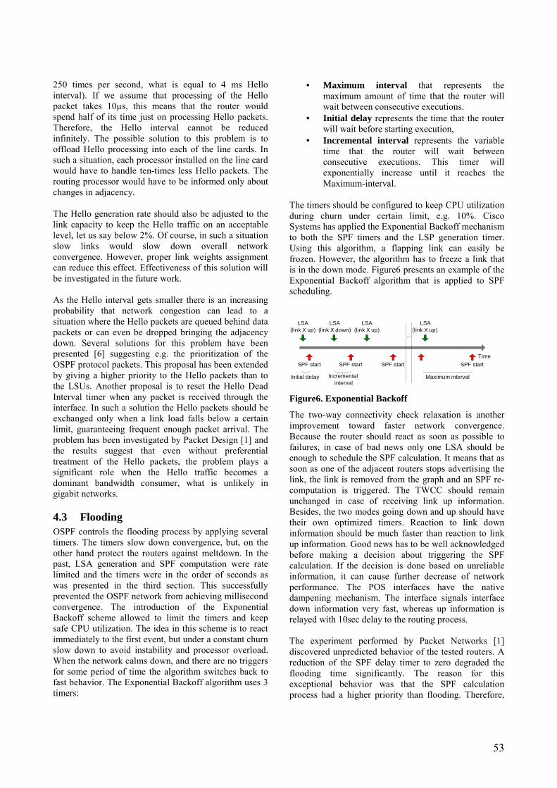
53
250 times per second, what is equal to 4 ms Hello interval). If we assume that processing of the Hello packet takes 10µs, this means that the router would spend half of its time just on processing Hello packets. Therefore, the Hello interval cannot be reduced infinitely. The possible solution to this problem is to offload Hello processing into each of the line cards. In such a situation, each processor installed on the line card would have to handle ten-times less Hello packets. The routing processor would have to be informed only about changes in adjacency. The Hello generation rate should also be adjusted to the link capacity to keep the Hello traffic on an acceptable level, let us say below 2%. Of course, in such a situation slow links would slow down overall network convergence. However, proper link weights assignment can reduce this effect. Effectiveness of this solution will be investigated in the future work. As the Hello interval gets smaller there is an increasing probability that network congestion can lead to a situation where the Hello packets are queued behind data packets or can even be dropped bringing the adjacency down. Several solutions for this problem have been presented [6] suggesting e.g. the prioritization of the OSPF protocol packets. This proposal has been extended by giving a higher priority to the Hello packets than to the LSUs. Another proposal is to reset the Hello Dead Interval timer when any packet is received through the interface. In such a solution the Hello packets should be exchanged only when a link load falls below a certain limit, guaranteeing frequent enough packet arrival. The problem has been investigated by Packet Design [1] and the results suggest that even without preferential treatment of the Hello packets, the problem plays a significant role when the Hello traffic becomes a dominant bandwidth consumer, what is unlikely in gigabit networks.
4.3 Flooding OSPF controls the flooding process by applying several timers. The timers slow down convergence, but, on the other hand protect the routers against meltdown. In the past, LSA generation and SPF computation were rate limited and the timers were in the order of seconds as was presented in the third section. This successfully prevented the OSPF network from achieving millisecond convergence. The introduction of the Exponential Backoff scheme allowed to limit the timers and keep safe CPU utilization. The idea in this scheme is to react immediately to the first event, but under a constant churn slow down to avoid instability and processor overload. When the network calms down, and there are no triggers for some period of time the algorithm switches back to fast behavior. The Exponential Backoff algorithm uses 3 timers:
• Maximum interval that represents the maximum amount of time that the router will wait between consecutive executions.
• Initial delay represents the time that the router will wait before starting execution,
• Incremental interval represents the variable time that the router will wait between consecutive executions. This timer will exponentially increase until it reaches the Maximum-interval.
The timers should be configured to keep CPU utilization during churn under certain limit, e.g. 10%. Cisco Systems has applied the Exponential Backoff mechanism to both the SPF timers and the LSP generation timer. Using this algorithm, a flapping link can easily be frozen. However, the algorithm has to freeze a link that is in the down mode. Figure6 presents an example of the Exponential Backoff algorithm that is applied to SPF scheduling.
Time
Initial delay
LSA(link X up)
LSA(link X down)
SPF start SPF start
Incrementalinterval
LSA(link X up)
SPF start
...
LSA(link X up)
SPF start
Maximum interval
Figure6. Exponential Backoff
The two-way connectivity check relaxation is another improvement toward faster network convergence. Because the router should react as soon as possible to failures, in case of bad news only one LSA should be enough to schedule the SPF calculation. It means that as soon as one of the adjacent routers stops advertising the link, the link is removed from the graph and an SPF re-computation is triggered. The TWCC should remain unchanged in case of receiving link up information. Besides, the two modes going down and up should have their own optimized timers. Reaction to link down information should be much faster than reaction to link up information. Good news has to be well acknowledged before making a decision about triggering the SPF calculation. If the decision is done based on unreliable information, it can cause further decrease of network performance. The POS interfaces have the native dampening mechanism. The interface signals interface down information very fast, whereas up information is relayed with 10sec delay to the routing process. The experiment performed by Packet Networks [1] discovered unpredicted behavior of the tested routers. A reduction of the SPF delay timer to zero degraded the flooding time significantly. The reason for this exceptional behavior was that the SPF calculation process had a higher priority than flooding. Therefore,

54
the router chose to do SPF calculation first. As a result the flooding time was equal to O(diameter*SPF time). The priorities should be configured to give higher priority to flooding. In addition, faster flooding requires reduction or even elimination of the Pacing-timer that, if left in its present form, efficiently prevents the flooding process from reaching wire speed.
4.4 Routing table update The easiest improvement to SPF calculation and routing table update processes is to decouple SPT and RIB. In case of topology change (node, link) both SPT and RIB should be re-computed as in standard implementation. However, if only the prefix has changed the changes are needed only in RIB. Therefore, a single prefix change does not require new SPF calculation that can decrease the convergence time significantly. The Incremental-SPF (I-SPF) scheme can further decrease the convergence time. When topology changes, instead of building the SPT from scratch the I-SPF only rebuilds the part of SPT affected by the change. This improvement assures that only the RIB entries related to subnets advertised by the re-analyzed nodes can change, e.g. if a link that was not a part of SPT calculated previously goes down, or if a new leaf node is added to the network, the previous SPT does not need to be recalculated. The more changes happen far away from the root node (the calculating router), the less computation is needed. Performed tests proved an average 80% gain of this algorithm [6].
Figure7. Incremental-SPF vs. conventional SPF algorithm[1].
In order to speed up the new route calculation process further, the routers in the network should maintain more than one set of routing tables. In case of predicted failure, the router just needs to swap the previous routing table with the new pre-computed one. Besides, the OSPF implementation should avoid scheduling the SPF
calculation in a situation where LSDB is updated by a new LSA which, as a result of the LSA refreshment process, carries the same routing information as the withdrawn instance of the previous LSA. Another improvement could be to report only the best parallel point-to-point adjacency decreasing number of links used in the SPF calculations. Current routers do not also preempt the SPF calculation even if during the SPF calculation new topology information arrives. The preemption can be reasonable in cases of long SPF calculations. The study of the SPF calculation times presented in [1] discovered that the SPF algorithm implemented in the operator class routers has poor scaling properties. Figure 7 presents the SPF calculation time in milliseconds versus the number of nodes in the network. SPF implementations in the Cisco and Juniper platforms (top three curves) are much more CPU intensive than the implementation of I-SPF algorithm (bottom line). The top curve fits perfectly the O(n2) Dijkstra algorithm, while the two middle curves represent O(nlogn) Dijksta implementation. 5 Conclusions The IGP convergence must be optimized in order to fulfill the strict requirements of real time services. Improvements to conventional OSPF protocol presented in the paper aim at speeding up convergence without stability compromise. Scalable, distributed router architectures together with liquidation of various unnecessary timers can lead to milliseconds convergence, therefore increasing network performance and customer satisfaction. References
[1] Alaettinoglu C., Jacobson V., Yu H., �Towards Milli-Second IGP Convergence�, Internet draft: draft-alaettinoglu-ISIS-convergence-00, 2000.
[2] Alaettionoglu Cengiz, Casner Stephen, �Detailed Analysis of ISIS Routing Protocol on the Qwest Backbone�, NANOG 24, February 2002.
[3] Boutremans Catherine, Iannaccone Gianluca, Diot Christophe, �Impact of link failures on VoiP performance, 12th International Workshop on Network and Operating Systems Support for Digital Audio and Video (NOSSDAV). Miami. May 2002.
[4] Casner Steve, Alaelletinoglu Cengiz, Kuan Chia-Chee, �A Fine-Grained View of High-Performance Networking�, NANOG 22, May 2001.
[5] Cisco Web Page, www.cisco.com [6] Choudhury G. L., �Prioritized Treatment of
Specific OSPF Packets and Congestion

55
Avoidance�, Internet draft, draft-ietf-ospf-scalability-07, 2004.
[7] Filsfils Clarence, "Deploying Tight-SLA services on an IP Backbone", RIPE 41, January 2002.
[8] Filsfils Clarence, �Fast IGP Convergence�, NANOG 29, October 2003
[9] Financial Times, �A disruptive technology: how the rise of the internet telephony is shaking up America�s communication giants�, 13 April 2004.
[10] Hengartner Urs, Moon Sue, Mortier Richard, Diot Christophe, �Detection and Analysis of Routing Loops in Packet Traces�, SIGCOMM IMW. Marseilles, France. Nov 2002
[11] Iannaccone Gianluca, Chuah Chen-nee, Mortier Richard, Bhattacharyya Supratik, Diot Christophe, �Analysis of link failures in an IP backbone�, Sprint labs, Internet Measurement Workshop 2002.
[12] Jiang Wenyu, Schulzrinne Henning, �Assesement of VoIP Service Availability in the Current internet�, Passive and Active Measurement Workshop 2003.
[13] Klimo Martin, �Calculation of Packet Loss Impact for E-model�, http://portal.etsi.org/stq/workshop/01MartinKlimoPresentation.ppt
[14] Labovitz Craig, Ahuja Abha, Jahanian Farnam, �Experimental Study of Internet Stability and Wide-Area Backbone Failures�, Twenty-Ninth Annual International Symposium on Fault-Tolerant Computing, 1999.
[15] Manasi Deval, Hormuzd Khosravi, Rajeev Muralidhar, Suhail Ahmed, Sanjay Bakshi, Raj Yavatkar, �Distributed Control Plane Architecture for Network Elements�, Intel Corporation, 2003
[16] Ohaka Yasuhiro, Bhatia Manav, Nakamura Osamu, Murai Jun, �Route Flapping Effects on OSPF�, Saint 2003 Workshop.
[17] Papagiannaki Konstantina, Moon Sue, Fraleigh Chuck, Thiran Patric, Diot Christophe, �Measurement and Analysis of Single-Hop Delay on an IP Backbone Network�, IEEE Journal on Selected Areas in Communications. Special Issue on Internet and WWW Measurement, Mapping, and Modeling, 3rd quarter. , 2003
[18] Shaikh Aman, Greenberg Albert, �Experience in Black-Box OSPF Measurement�, AT&T Labs, Internet Measurement Workshop 2001.
[19] Thadani Navin, Donner Paul, "Making VoIP live up to the PSTN. The importance of routing optimization in high availability", CED, October 2003, http://www.cedmagazine.com/ced/2003/1003/10e.htm
[20] Villamizar Curtis, �Convergence and Restoration Techniques for ISP Interior Routing�, NANOG 25, June 2002.
[21] Moy John, �OSPF Version 2�, RFC 2328, April 1998
56
Site Multihoming: A Microscopic Analysis of Finnish Networks
Pekka Savola CSC/FUNET
[email protected] Abstract This paper examines the extent of site multihoming in Finnish networks. Global route advertisements have been analyzed in general in a couple of studies, but this has not yielded sufficient information about the unclear cases of site multihoming. As these macroscopic approaches to analyze site multihoming have not succeeded, I analyze the questionable route advertisements in a "microscopic" fashion, checking them one by one. This research leads me to conclude that more specific route advertisements through a different path than the aggregate do contain quite a few multihomed prefixes: a large number of the sites which have an AS number are multihomed, even though they would seem to be visible through one path only, while more specific routes advertised by other ISPs have a smaller chance (around 15%) of being multihomed. In addition, I confirm the obvious result that site multihoming with your own AS number and identical route advertisements through multiple providers is on the rise; some of these (at least 17%) do not have their own address space. This paper also discusses the challenges of developing a good multihoming solution, and describes the scalability problems with current BGP multihoming. 1 Introduction This paper analyzes the route advertisement data gathered at a Finnish Exchange point (FICIX) to get a feel about the extent and mechanisms of site multihoming. This builds on and extends the author's earlier work on more generic routing advertisement analysis [1]. Multihoming is the process of obtaining simultaneous IP connectivity from multiple ISPs for a number of reasons such as protection against failures. Site multihoming is a subset of that: the case where an end-site, for example an enterprise, obtains multihoming. This paper describes the site multihoming background, motivations, challenges, techniques, and problems in section 2. Section 3 describes the research and data collection methods used prior to writing this paper. Section 4 analyzes the collected data at length. Section 5 discusses future work, and section 6 concludes the paper. Throughout this paper, familiarity with addressing, routing, BGP, etc. is assumed. See [1] for a longer introduction. 2 Site Multihoming This section gives background to the research: it describes the different multihoming types, the reasons for multihoming, challenges for multihoming solutions, multihoming techniques, and problems with those techniques.
2.1 Terminology In this paper, multihoming refers to the process of obtaining simultaneous IP connectivity from multiple ISPs. "Multiconnecting" or "Multi-attaching", on the
other hand, refers to obtaining simultaneous IP connectivity from the same ISP. This paper focuses on multihoming as defined above, even though some also count multiconnecting as multihoming. It is possible to divide multihoming to three categories: node multihoming, site multihoming and ISP multihoming. Node multihoming refers to a single node connecting simultaneously to multiple operators to obtain IP connectivity. This is considered to be out of the scope of this paper. Site multihoming refers to a whole end-site, for example an enterprise, connecting simultaneously to multiple operators. ISP multihoming refers to an ISP, also providing access to sites, connecting simultaneously to multiple upstream ISPs. This is often also referred to as "IP transit". ISP multihoming is a trivial case, as the ISPs are expected to have their own addresses and AS numbers, and is out of the scope of this paper.
2.2 Motivations There are a number of motivations why a site might multihome, some of them a lot more obvious than the others. These are [2,1]:
• Independence: being able to switch ISPs easily, without renumbering; being seen as independent also often has some "status value".
• Redundancy: being able to protect yourself from a number of problems affecting the site's usability or availability, such as fiber cuts, hardware or software problems, specific configuration mistakes, etc. -- this is a generic

57
motivation for increasing resiliency against failures.
• Load sharing: being able to distribute the incoming and outgoing traffic among different links or operators.
• Performance: some traffic may have different requirements (e.g., low delay, packet loss, or jitter) and one wishes to obtain high-quality connectivity for that traffic; on the other hand, some other traffic may not have these requirements, and could be satisfied using a lower-quality operator.
• Policy: some organizations (e.g. universities) may have policies regarding what kind of traffic (e.g., commercial vs research) is allowed by the upstream provider.
These are described at more length in [1,2] In most cases, the most important motivation is redundancy. Independence is often also very desirable. The other three motivations are not as common.
2.3 Challenges Designing a good site multihoming solution has a number of challenges, which make it difficult to find an approach without significant drawbacks. Fine-grained traffic engineering is complicated: outbound traffic engineering is a relatively simple process, but inbound traffic engineering is very complicated. That is, to be able to affect decisions made by any node in the Internet, one has to distribute the traffic engineering information throughout the Internet. About the only way at the moment to do that is to use BGP to advertise a route (often a more specific route) with intended visibility to steer the traffic. Connection survivability is important: when outage happens and one should fall back to IP connectivity for another provider, existing TCP connections, UDP "sessions", etc. should continue to work without being reset � which would happen if the IP addresses changed and the protocol suite did not offer connection survivability. Network renumbering is painful: it takes a lot of work to change IP addresses in all the nodes at the site -- and also those hosts which are not at the site which have been configured to use the IP addresses. Therefore, networks typically want to use either provider independent addresses, or NATs (where applicable) to avoid biggest renumbering pains if they would have to switch ISPs. It is vital to keep renumbering as simple as possible, as the other alternative is provider-independent addresses which have problems of their own. For more information about renumbering procedures, see [4,5].
The Internet routing infrastructure must be scalable: all of these challenges could be satisfied by assigning every site with provider-independent addresses, and having those advertised to the whole Internet through multiple providers. However, this would not scale for multiple reasons. Such updates require 1) processing power, i.e. CPU, 2) memory to hold the number of prefixes, and 3) sufficient link bandwidth for updates. Especially the first can be a problem even with high-end equipment, particularly if failures could come as bursts as well. 2.3.1 Scalability Challenges The scalability is probably the most significant challenge because it's all the ISPs in the Internet who have to face the scalability burdens, not the multihomed site itself. Therefore the site has no clear incentive to use a scalable mechanism. This is further described in the next subsection, and discussed in a bit more length in section 2.5 in the context of an unscable solution. The scalability concern needs to be analyzed; [1] makes some rough estimates. Let us look at two cases: a scenario where every enterprise of at least a) 50 employees, or b) 500 employees would have a multihoming solution affecting the global routing infrastructure. Calculation with a population mass of 1000 million (only), and enterprise density of a) 1000 and b) 50 per million people ([1] justifies why these numbers are reasonable), we would have a) 1,000,000 or b) 50,000 multihomed sites. Depending on the estimated error rates in the different components and systems in the network (see e.g. [1] for an approximation), this might result in the order of O(100,000) updates per day, with bursts up to O(100,000) simultaneous changes when failure occurs somewhere in the network.
Figure 1: Number of BGP Updates from Internet, by
hour

58
Actually, this is probably an underestimation; Figure 1 shows the measurements of the number of BGP updates in the full Internet routes (around 140,000) entries as of April 2004. During 24 hours, there were about 64,000 updates, averaging 44 updates per minute (This is just a measurement of the global routing table on one day, as heard from AS2603, not a long-term average.). As is expected, most instability occurs around the hours 02-10 (UTC), which seems to correspond to the maintenance windows after the office hours in North America. One may want to compare this to [9,10]; in particular, in 2002, Sprint network reported higher churn for eBGP sessions, around 100 updates/minute [10]. So, it seems relatively obvious that this would not be scalable: a different protocol, with more powerful data aggregation or computational facilities- for example, calculating the equivalence classes of prefixes based on the ISPs' Autonomous System (AS) numbers- would be necessary; even better would be avoiding unscalable mechanisms in the first place.
2.4 Techniques There are a couple of ways to multihome using IPv4, some more popular than others. In IPv6, there has been desire to avoid the unscalable mistakes of IPv4 multihoming, and the solution space is still being explored, and looks a bit different [3,1]. 2.4.1 Multihoming with BGP The most visible and complete form of multihoming is done with BGP, with the following steps:
• obtaining your own IP address space, or getting permission to advertise a more specific route of an ISP's aggregate
• obtaining an Autonomous System (AS) number • obtaining physical connectivity to at least two
ISPs • establishing BGP sessions between the ISPs and
the site border router routers, advertising the address space
• selecting which links will be used for the incoming/outgoing traffic by configuring BGP
There are a few shortcuts one can make (e.g., using a more specific prefix rather than getting your own addresses), but this is the most complete and common procedure. 2.4.2 Multihoming with NAT A partial solution to multihoming is using NAT and deploying a specific device at the border which picks the right ISP to use without having to run a routing protocol on the customer link [1]. This does not give the full benefits of multihoming, e.g., connection survability is
missing, but nonetheless the NAT solutions have been deployed at some smaller sites. As this is not a visible form of multihoming- to the rest of the network in any case- this is not further analyzed here. 2.4.3 Multihoming in IPv6 Site multihoming in IPv6 [3] is a subject very much under debate. There seems to be two major focal points: deploying multiple addresses on the nodes (from each ISP the site connects to, avoiding provider-independent addresses) and solving the connection survivability problem. (Traffic engineering would still remain an open issue.) The connection survivability problem could be tackled by using mechanisms which can automatically switch between multiple addresses as appropriate; this often leads to the concept of separating the identity and the topology-wise location of a node. This is similar to what SCTP is doing for a single (new) transport protocol. The separation of an address to a routing locator and a host identifier is by no means a trivial change, as that brings a large number of new security threats [6].
2.5 Problems with Multihoming Techniques
Site multihoming using an architecturally unscalable fashion, BGP, is too cheap: practically it costs nothing. Most costs are incurred from the equipment, the physical connectivity, and the expertise (e.g. consultants or own staff). Compared to that, fees to Regional Internet Registries (RIRs) such as RIPE are not significant: in the order of a thousand EUR per year. Compared to that, the expenses required for redundancy, e.g. two access links to the ISPs and two border routers seem much more significant. This leads to the "grazing the commons" effect: everyone wishes to use the most complete site multihoming solution, BGP, and likely does not want to settle for less. To fix that, there would have to be a fee for the use of the global routing infrastructure (e.g. 5,000 EUR/year plus 500 EUR/year for every originated prefix, collected by RIRs and donated in full to Internet Society), but such a thing would be an administrative impossibility; one would have to answer questions such as: How would this be observed? By whom? What constitutes "global"? What would prevent someone from advertising but not paying the fee? The only hope would be (1) developing alternative mechanisms so that they are usable (as is being done with IPv6 now), to satisfy also e.g. traffic engineering requirements, and (2) raising (artificially) the fees for the resources such as AS numbers so that they would only

59
be used by those who really do need them. (This has a number of problems of its own, though.) 3 Research Method and Data
Collection In this section, the used research method is described and justified, and the data collection procedures and analysis are described.
3.1 Research Method Few studies have been made trying to characterize the global routing infrastructure patterns from the perspective relevant to site multihoming. On the other hand, the routing advertisement characteristics have been analyzed in general by a few people [7,8]. [1] presents the rough state of site multihoming on Finnish networks. One reason for the lack of extensive study may be that the advertisements give relatively little detailed information; the advertisements yield some statistics, but due to a number of uncertainties, drawing conclusions based on these results on the use of multihoming is very difficult or even impossible. As a result, as macroscopic approaches to analyze site multihoming have not produced sufficient results, I try to use a "microscopic" approach instead: I focus on a relatively small subset of Internet routing by looking at Finnish networks only, examining each case individually, and try to draw conclusions based on that study. One should be able to assume that the multihoming patterns in Finland give at least a feel of a more global trend. In this paper, I analyze the BGP routing advertisements at one of the two major Finnish points, FICIX2. Practically all the Finnish Internet traffic goes through these two exchange points, so analysis there should yield a rather good view on the extent of multihoming in Finnish and (to an extent) neighboring networks.
3.2 Data Collection FICIX [11] is a Layer 2 exchange, where offering transit is prohibited. So, all BGP sessions are pure peerings. The author works at CSC -Scientific Computing Ltd which is present in FICIX. Data is collected by taking a weekly snapshot of BGP routes (with all the associated data) advertised by peers. Note that BGP only advertises the best paths, but as all the significant Finnish ISPs connect to FICIX, no information is lost provided that:
• "ISPs behind ISPs" are insignificant
That is, those ISPs which do not connect to FICIX but operate in Finland are not considered sufficiently interesting for the purposes of this analysis. Only a few prefixes and ASs are present this way.
• ISPs prefer their own routes to those that they have heard
The question is whether you prefer your own prefix if a neighbor advertises the same prefix as you do but with better parameters (e.g. a shorter AS-path). The behavior depends on how the ISP prefers the routes it has heard from the neighbors; typically this can be done either using BGP local-preference or MED attributes. Local preference would practically always prefer the local path, but MED would prefer the heard path if the local path's AS-path had been prepended by the customer. So, while this does not give complete assurance of a full view, it is thought to be sufficient for most cases. The route advertisements have been stored since June 2002, but unfortunately there are a few gaps in the data. This also allows to observe how multihoming may have changed over time. However, this paper focuses on the situation as of April 2004. It is also worth noting that during the data collection, both FICIX exchanges have transited from ATM-based connectivity to Gigabit Ethernet connectivity. Some members have not re-connected immediately before/after these changes, which has caused temporary distortions to the data (seen as sites ceasing to be multihomed and coming back to multihomed when reconnecting).
3.3 Data Analysis Analysis of the route advertisements provides some insight [1], but is not sufficient for making reasonable conclusions. Therefore the methology also leverages the following to better analyze the internal topology of the ISPs in a few scenarios where more information is needed:
• Running traceroutes to specific destinations from a server or looking glass in the ISP's network, or looking at the internal routes at a route server or looking glass (if available and yielding sufficient information)
• Observing the intended routing policy for an AS in the RIPE routing database [12]
• Querying the ISPs directly, by asking them to clarify the advertisements [1]
• Querying the questionable end-sites directly, by asking them whether they are multihoming or not

60
To elaborate on the first point: when analyzing whether a more specific route from a different path could be a sign of multihoming or not (see section 4.4), one can try to approach this by trying to traceroute to the more specific prefix from the ISP of the aggregate prefix. If there is direct connectivity to the more specific route's network, the site is multihomed. If the connectivity goes through the Internet exchange, very likely there is no multihoming. That is, this makes an assumption that some form of connectivity would have to be active at the backup ISP even before the more specific route has failed. There are a couple of ways how one can configure the network so that this assumption is not valid, but it should apply in most cases, so it is used for analysis here. I also considered to build a system which would constantly monitor the route advertisements and if an interesting prefix would get withdrawn (e.g., due to suspected outage), try to reach the site using an alternative path (i.e. through the less specific aggregate). However, this turned out to be quite complex so it is left for further study. 4 Data Analysis In this section, the route advertisements are categorized, a few observations about the advertisements in general are described, and then the three potential multihoming types are described and analyzed at length.
4.1 Categorizing the Advertisements Route advertisements could be classified in roughly six categories:
• Single-homed prefixes, for which there are no more specific routes ("root prefixes")
• Single-homed prefixes which are being given transit by another ISP, i.e., an ISP is doing "ISP multihoming" (see Figure 2)
• More specific prefixes with the same path and origin as the less specific prefix (see Figure 3)
• More specific prefixes with a different path or origin than the less specific prefix (see Figure 4)
• Equal-length prefixes advertised from a different origin (see Figure 5)
• Equal-length prefixes advertised from the same origin but through different paths (see Figure 6)
Figure 2: Case 2: ISP multihoming
Figure 3: Case 3: More specifics along the same path
Figure 4: Case 4: More specifics from a different
origin

61
Figure 5: Case 5: Same prefix from different
path/origin
Figure 6: Case 6: Clearly multihomed
Of the six categories listed above, the first are not interesting from the multihoming perspective as the prefixes are single-homed and they have no more specific routes which could potentially be multihomed. The second are not interesting from the site multihoming perspective as it is a form of ISP multihoming. The third come the same path as the less specific prefix and can not be multihoming but rather traffic engineering, configuration mistakes, i.e. the result of improper aggregation, etc. These are not described at more length in this paper. The fourth can be either the sites switching operators but taking the IP addresses with them, improper aggregation (i.e. an ISP advertising an aggregate even though that should not be done), or a special kind of multihoming using provider-dependent addresses. It is impossible to distinguish these cases based on the route advertisements alone, so they have to be further analyzed using the other methods. I call this type B multihoming. The fifth is a rare case where multiple ASs advertise the same prefix. This is done e.g. with certain anycast prefixes (such as anycast root nameserver addresses [13]), but is indistinguishable from prefix hijacking. However, this could also be multihoming in the case
where the site does not have a (public) AS number. I call this type C multihoming. The sixth is a clear case of multihoming; this can happen with either your own IP addresses (i.e., the prefix advertised is also a root prefix), or a more specific chunk from an operator's address space. I call this type A multihoming.
4.2 Prefix Advertisements Before analyzing the multihoming characteristics, I take a quick look at prefix advertisements in general. Figure 7 depicts the number of route advertisements per peer, and all the advertisements in total. One can observe a jump up from February 2003 in the advertised prefixes, and downfall at the end of 2003. This is due to the presence of a larger carrier, BT Ignite (AS5400), in the exchange. However, it no longer participates in FICIX2 where these snapshots have been taken. Apart from that, the number of prefixes has risen from around 1300 in July 2002 to around 2200 in April 2004. Sonera (AS1759) is also well represented, mainly due to the fact that it is advertising its Russian and Baltic customers' routes in FICIX as well. The rest are either in the category of a couple of hundred prefixes, or in the category of a couple of dozen prefixes or less. Unfortunately, data from November 2003 to February 2004 is missing.
Figure 7: Prefix Advertisements
See Appendix A.1 to see which organizations correspond to which neighbors' AS numbers. It is worth noting that AS9060 no longer exists, AS790 has merged with AS6667, AS20569 has merged with AS16086 and AS6793 has merged with AS3246.
4.3 Case 6: Type A Multihoming Figure 8 shows the total number of multihomed sites, measured by the number of ASs. Again, due to the presence of a larger carrier during the most of 2003, the

62
data does not give a good view of the situation. The figure also lists the number of new ASs and removed ASs, compared to the previous month. This gives an idea of the dynamic nature of multihoming. The number of multihomed sites has risen from 16 in July 2002 to 30 in April 2004 (i.e., 88\% increase over 21 months). Even in the "stable" topologies there is still fluctuation with the sites: about every month a couple of new sites crop up, and a few old ones disappear. Type A multihomed ASs are listed in the Appendix A.2.
Figure 8: Type A Multihoming
Let's compare the situation of April 2004 (see Appendix A.2) to that of April 2003 (see Appendix A.3), ignore the non-Finnish changes, and do a bit of investigation. We see:
• Nokia has started multihoming more aggressively with AS1248. It has recently joined a FICIX member as well.
• Kemira (AS5420) is no longer multihomed through AS5400 (This is due to lack of visibility of AS5400 in FICIX2; it is still present at FICIX1, so Kemira is actually still multihomed.)
• Oulu Telephone Company (AS12375) has more or less merged with AS16086, and the connectivity to AS3246 seems to have been taken down, no longer making it multihomed.
• Suomi Communications (AS16302) is not even in the routing table anymore. Its prefix is advertised, single-homed, by Nebula Networks (AS29422); AS29422 is also a recently joined new FICIX member. One can guess the first has either ceased operations or been sold.
• Tumsan Network (AS16331) is no longer multihomed through AS5400 (This is due to lack of visibility of AS5400 in FICIX2; it is still present at FICIX1, so Tumsan Network is actually still multihomed.)
• TietoEnator (AS24714) was multihomed through two providers. The AS is no longer visible at all. The prefixes have been moved to TietoEnator's another AS, AS375, and are single-homed in FICIX.
• Power-IT (AS24752) was multihomed through AS16086 and AS12375, but when AS12375 more or less merged with AS16086, the multihoming property was (apparently) lost.
• Partek (AS25213) was single-homed to AS3246 with its /16 prefix, but obtained an AS and started multihoming to AS6667 as well.
• Fingrid (AS29093) was not seen (either the /24 prefix or the AS) in 2003, but is now multihomed.
• MMD Networks (AS29243) had its /20 prefix routed single-homed from AS3246, but has obtained an AS, and started multihoming through AS6667 as well.
• TNNet (AS30798) was not seen (either the /20 prefix or the AS), but is now multihomed through three providers.
To summarize: ISP acquisitions/mergers change the multihomed status of the sites; some ISPs cease operations and their address space may or may not "live" on; a number of organizations which have their own addresses can easily start multihoming just by getting an AS number; multihoming seems to be on a slight rise. I also examined how many of the multihomed sites in April 2004 were using part of their provider's aggregate, and how many of them had their own IP addresses. 5 of 30 sites (17%) did not have their own address space.
4.4 Case 4: Type B Multihoming Figure 9 shows the number of less specific routes, with a different path than the more specific route, advertised by the neighbor AS. In other words, this shows which aggregates (advertised by whom) are being "punched through" with a certain kind of more specific routes. The figure only includes the routes where the more specific route is advertised from a different path than the aggregate.

63
Figure 9: Type B Multihoming: distribution of less
specific routes
Figure 10 shows the number of more specific routes, with a different path than the aggregate, advertised by the neighbor AS. One can compare these two figures. One conclusion is that Elisa (AS719) is advertising (relatively) many more specific routes than others (compare this to Sonera (AS1759) and the combination of Eunet and Jippii (AS790 and S6667), for example). The advertisement of more specific routes with a different path appears to be on a slight rise, but this is not conclusive.
Figure 10: Type B Multihoming: distribution of more
specific routes
Obviously, not all of these are an instance of type B multihoming: they are just the ones that could be. To get a better idea of the extent of type B multihoming, compared to just changing providers, I have investigated the more specific routes in detail using public traceroute servers, looking glasses, personal home computer, and querying an operator in question; thismethodology was described at more length in section 3.3. I have managed to obtain this information from AS719, AS1759, AS3246, AS6667/790, and AS16086. In other words, all the relevant ISPs which had an aggregate
where more specific routes with a different paths were being advertised. I categorized the cases as follows:
• Sites where the more specific route is originated by the site with an AS number, and may be multihomed
• ISPs advertising more specific routes which might be multihoming if the site uses private AS numbers or the advertisements are proxied by the ISP, or some IGP such as OSPF is used instead of BGP
• Illogical cases, e.g. where an ISP is advertising a more specific route, overriding a part of a site's aggregate
• Prefixes relating to internal reorganization of an ISP, where the ISP uses multiple AS numbers
• Prefixes which I excluded due to insufficient advertisement coverage (mostly Russian, Baltic or Swedish/Norwegian prefixes)
These are analyzed at more length in the following subsections. 4.4.1 Sites with an AS Number For the first category, the extended test results were as follows:
• AS375 (TietoEnator) has about 40 more specific routes from different operators' aggregates. These do not seem to be multihomed (based on traceroute results), and RIPE database has no import/export policies for AS375 either. TietoEnator has at least one, but possibly more, private peerings.
• AS8812 (Nokia Mobile Phones Wireless Future Lab) has a prefix which is advertised through one path only. However, a note in the AS-macro indicates that the backup advertisement becomes active only when the first one disappears, so they may in fact be multihomed; this is impossible to test.
• AS3274 (Cygate) has a couple of prefixes that it is advertising using just one path, while some others use type A multihoming. Based on traceroutes, these prefixes do not seem to be multihomed. This may be a configuration/policy problem.
• AS20774 (Univ. of Jyväskylä Commercial Services) advertises two more specific routes through AS1759. Their AS-macro indicates that they are multihoming to AS6667 as well, and traceroutes from AS6667 indicate that this is the case. Note that AS20774 is already doing type A multihoming for their own addresses.

64
• AS28883 (Samlink) has a /24 prefix which is advertised only through the owner of the aggregate. AS-macro indicates that they should advertise it through another provider, UUnet (AS702) as well, but that is not present at FICIX. However, traceroute from UUnet's looking glass indicates that this network is in fact multihomed.
• AS29240 (Nordic Lan & Wan) has a /19 prefix, but only advertises a more specific route through their other provider. AS-macro indicates that they should be multihoming through two providers. I conclude that their multihoming set-up is mostly broken, but still functioning to a degree.
• AS29601 (UPM-Kymmene) has about 6 prefixes which are advertised only through AS1759. Their RIPE DB AS-macro states that some prefixes should be multihomed using AS2874, and the AS-macro of AS2874 agrees. However, this is impossible to verify as there is no looking glass to use; running traceroute from a few networks associated with AS2874, however, do not use this route, and it is probable that multihoming is not operational at the moment.
To summarize, those sites which have an AS number seem to have a rather high probability for having at least some kind of multihoming setup, even if they did not have their own address space. This is only logical as the AS number is only really needed if you are using BGP for advertising your prefixes to the whole Internet. 4.4.2 More Specifics from a Different ISP The second category, more specific routes from an ISP, not an end-site, produced the following results:
• 10 more specific prefixes advertised by AS719 can also be reached through the 3 aggregates advertised by AS16086.This is due to the special way these had been set up in the past. These can be counted as type B multihomed.
• There are about 80 more specific prefixes advertised by various ISPs, under about 23 aggregates. There appears to be no indication of multihoming, just switching providers. These were tested by running traceroutes manually.
• There are 5 more specific prefixes advertised through various ISPs, which seem to be reachable through 4 aggregates, as measured with traceroute. These prefixes are: 192.126.19.0/24, 193.94.100.0/24, 193.94.101.0/24, 194.136.72.0/23, 194.215.50.0/24. There are reasonable grounds to believe these may be type B multihomed.
To summarize, the situation with more specific routes originating at ISPs' networks seems to be a bit more worse, multihoming-wise, than expected; in [1] I estimated the ratio to be between 30-50%, but it appears that it is apparently closer to 15% (or so). 4.4.3 Illogical Advertisements and Others The third category, illogical advertisements, includes a few interesting entries:
• AS764 (Prime Minister's Office) has an AS, but is only advertising through one provider, and the AS-macro indicates the same. One can wonder why to have an AS number in the first place if not multihoming; this is probably a historical remnant as the AS number was assigned a long time ago.
• AS5420 (Kemira) advertises a /21 (through AS3246), but AS1759 advertises a more specific route overriding a part of that. The more specific route is not directly reachable through AS3246. The AS-macro indicates that the organization should be multihoming, but one AS listed does not exist, and the other one does not provide transit. Despite these inaccuracies, I already concluded that AS5420 is actually still type A multihomed through FICIX1; this more specific route is just an illogical advertisement.
• AS24752 (Power-IT) advertises prefixes on only one path, but its AS-macro indicates they are using both AS12375 and AS16086. However, nowadays AS12375's only upstream appears to be AS16086, so this form of multihoming does not show outside of AS16086, and is rather close to multiconnecting.
• AS25213 (Partek) advertises a /16 (through AS6667), but AS1759 advertises a more specific route overriding a part of that. The more specific route is not directly reachable through AS1759. This prefix was already identified as type A multihomed, but the more specific route is illogical.
• AS29132 (IW-Net) advertises a number of prefixes through AS6667, but AS3246 overrides a part of that. The more specific route is not directly reachable through AS6667. The AS-macro indicates that it should be multihomed but is hopelessly out of date and incorrect. It seems unlikely that there is multihoming here.
About 60 prefixes were excluded from the analysis as the more specific routes appeared to be coming from a different branch of the same ISP (for example, through path "719 5487" from 719).

65
About 130 prefixes were excluded from the analysis due to insufficient coverage- for example, routes originated in Russia, Baltic countries, Sweden/Norway, but which were advertised in Finland by international carriers. That is, as one can not get advertisement from every ISP that the organizations in these regions could be multihomed to, the data would be too partial to be useful for analysis. To summarize, some ISPs appeared to be advertising a small part of an aggregate; it is difficult to find justification for this- I can only guess that it is either related to connecting branch office(s) or advertised if the site has outsourced some infrastructure services (e.g. mail servers). The number of "internal organization" prefixes (especially coming from AS719) was surprisingly large. It is also interesting that the operators wish to exchange non-Finnish traffic at FICIX- but this is in the spirit of "hot potato routing".
4.5 Case 5: Type C Multihoming Excluding the anycast prefixes, only one real prefix (192.49.166.0/24) was originated by two different AS's during 2002 (learned through paths 719 and 1759 5515). This route is used by AS375. This might have been a configuration mistake, as AS375 is originating a lot of routes on its own and has no need for this kind of techniques. As noted, this is very rare. For example, analysis of full Internet routing table showed only 13 such prefixes as of April 2004 [7]. 5 Future Work There is always room for improvement. Non-Finnish networks being advertised caused a lot of disturbance and made real measurements of only Finnish networks more difficult. It might make sense to filter out such paths and prefixes after processing the data. It might also make sense to combine the data from FICIX1 and FICIX2 (I only analyzed FICIX2, because that dataset is more complete), to be able to include e.g. Finnish networks advertised by BT Ignite which is only present at FICIX1. However, such data exclusion lists would require a significant amount of work and manual maintenance. Also, one should examine whether one can reasonably assume that all type A multihomed networks have indeed been detected; this depends a lot on the assumptions how secondary ISPs have been set up, as described in section 3.2. This should be explored at more length, e.g. through looking glasses (if available and yielding sufficient information).
Section 4.4.1 noted that more specific routes from site's own AS are a common source of multihoming. It might also make sense to examine the root prefixes heard from sites' AS numbers. This should also catch the cases which fail the type A multihoming detection assumptions above. 6 Conclusions Based on the investigation, one can conclude that: Type A multihoming, i.e. advertising identical prefixes from multiple paths, can be relatively easily distinguished with a few caveats (Such as how "secondary" ISPs prefer the advertisements heard from primary ISPs, depending on the techniques used. See section 3.2 for details.). This form of "complete" multihoming has been on the rise. Some sites (at least 17%) use more specific routes from their ISP, not getting their own address space. Analysis of apparent changes in this class during a year indicates that some sites have first obtained address space and are single-homed, and later obtain an AS number and start multihoming. Furthermore, the analysis shows that ISP reorganizations/mergers affect the site multihoming of the sites multihoming to those ISPs and that a few (although a lot less than new multihomers) ASs have indeed stopped multihoming. Type B multihoming, i.e. advertising a more specific route from a different path, is more common. However, the research seems to indicate that a significant portion of these is just switching providers without renumbering, not type B multihoming. When a more specific route was advertised by site's AS number (and not an ISP's), type B multihoming was quite common. More specific routes advertised by other ISPs, however, had a lot smaller degree of type B multihoming, around 15% at most. Type C multihoming, i.e. originating the same prefix from two ASs is very rare. There seem to be reasonable grounds to believe that this is close to non-existnt technique for multihoming and can be ignored. Additionally, one should be aware of the challenges of multihoming (section 2.3) and problems with the mechanisms (section 2.5): in particular, what kind of scalability problems seem inevitable with thecurrent BGP multihoming approaches. Preventing them may be very difficult as the costs are borne by the ISPs, not sites themselves. List of acronyms DVMRP: Distance Vector Multicast Routing Protocol IANA: Internet Assigned Numbers Authority IETF: Internet Engineering Task Force

66
IGMP: Internet Group Membership Protocol ISP: Internet Service Provider MBGP: Multiprotocol Border Gateway Protocol MBONE: Multicast backbone MOSPF: Multicast Open Shortest Path First OSPF: Open Shortest Path First P2P: Peer to peer PIM: Protocol Independent Multicast QMRP: QoS aware Multicast Routing Protocol RIP: Routing Information Protocol RP: Rendezvous Point RPF: Reverse Path Forwarding WWW: World Wide Web References
[1] C. Kenneth Miller, Multicast networking and Applications, Addison Wesley, September 1998.
[2] IP Multicast Technology Overview, http://www.cisco.com/univercd/cc/td/doc/cisintwk/intsolns/mcst_sol/mcst_ovr.pdf, Cisco, 2002.
[3] S. Deering, Host Extensions for IP Multicasting, IETF, RFC 1112, August 1989.
[4] D. Waitzman, C. Partridge, S.Deering, Distance Vector Multicast Routing Protocol, RFC 1075, IETF, November 1988.
[5] J.Moy, Multicast Extensions to OSPF, RFC 1584, IETF, March 1994.
[6] T. Bates, R. Chandra, D. Katz, Y. Rekhter, Multiprotocol Extensions for BGP-4, RFC 2283, IETF, February 1998.
[7] Protocol Independent Multicast � Sparse Mode, RFC 2362, IETF, June 1998.
[8] Interdomain Multicast Routing (IDMR) workgroup, http://www.ietf.org/html.charters/idmr-charter.html
[9] K. Sarac, K. Almeroth, Monitoring reachability in the global multicast infrastructure, International Conference in Network Protocols, Osaka, Japan, November 2000.
[10] A. Adams, J.Nicholas, W.Siadak, Protocol Indipendent Multicast- Dense mode, draft, PIM WG, IETF, September 2003.
[11] P. Rajvaidya, K.C. Almeroth, A router based technique for monitoring the next generation of internet multicast protocols, International Conference on Parallel Processing (ICPP), Valencia, Spain, September 2001.
[12] P. Rajvaidya, K.C. Almeroth, Analysis of the routing characteristics in the multicast infrastructure, Twenty-second Annual Joint Conference of the IEEE Computer and Communications Societies, INFOCOM 2003.
[13] K. Almeroth, The evolution of multicast: from the MBONE to inter-domain multicast to
Internet2 deployment, IEEE Network, January 2000.
[14] Introduction to the MBONE, http://www-itg.lbl.gov/mbone/
[15] B. Quinn, K. Almeroth, IP Multicast Applications: Challenges and Solutions, RFC 3170, IETF, September 2001.
[16] S. Chen, K. Nahrstedt, Y. Shavitt, A QoS-Aware multicast routing protocol, IEEE journal on selected arias in communications, vol.18, no.12, December 2000.
[17] S. Deering, Multicast routing in datagram internetwork, PhD dissertation, 1988.
[18] W. Fenner, Internet Group Membership Protocol, Version 2, RFC 2236, IETF, November 1997.
[19] C. Hedrick, Routing Information Protocol, RFC 1058, IETF, June 1988.
[20] J. Moy, OSPF, Version 2, RFC 1583, IETF, March 1994.
[21] Cisco IOS Software Multicast Services web page, http://www.cisco.com/go/ipmulticast
[22] J. Meserve, IP multicast still waiting for takeoff, Network World Fusion, October 2000.
[23] Analysis of the multicast traffic, http://www.caida.org/analysis/multicast
[24] C. Diod, B. Levine, B. Lyles, H. Kassem, D. Balensiefen, Deployment issues for the IP multicast service and architecture, IEEE network magazine special issue on multicasting, p.78-88, February 2000.
A AS Numbers and Changes A.1 Neighbors at Ficix The neighbor Autonomous Systems referred to in this document are: AS719 Elisa AS790 Eunet AS1342 Fujitsu Invia AS1759 Sonera AS2686 AT&T AS3246 Song AS5400 BT Ignite AS6667 Jippii AS6743 GlobalOne AS6793 Telivo AS8434 Utfors AS9060 <ceased> AS16023 Netsonic AS16086 Finnet AS20542 HTV AS20569 FinnetCom AS24751 Multi.fi

67
A.2 Type A Multihoming in April 2004 The type A multihomers, as of April 2004, are: AS1234 Fortum AS1248 Nokia * AS1738 Okobank * AS2129 Hewlett-Packard Europe AS3238 Alands Datakommunikation AS3274 Cygate Networks * AS3277 RUSNet [Russia] * AS12918 Verkkotieto AS13276 MagentaSites AS15501 PHNet Internet Services AS16051 Radiolinja AS16259 Xenetic AS16273 F-Secure AS20574 Teleca AU-System [Sweden] AS20774 Univ. of Jyvaskyla Commercial * AS20883 WM-Data CCB [Sweden] AS20904 Uta-Net AS21348 Kopteri.fi AS21856 Nokia e-Commerce AS24713 WM-Data AS24809 Sampo AS25213 Partek AS25417 Ljusnet [Sweden] AS25476 DK Network [Sweden] AS28702 Delta Telecom [Russia] AS29093 Fingrid AS29243 MMD Networks AS29518 Labs2 [Sweden] AS30798 TNNet AS31024 Malmo Aviation [Sweden] *) means that the AS also advertises one or more more specifics from an aggregate; it may or or may not have its own address block. The country of the organization, if not Finland, has been marked explicitly. A.3 Type A Multihoming in April 2003 The type A multihomers, as of April 2003 (for comparison), are: AS1234 Fortum AS1738 Okobank AS2129 Hewlett-Packard Europe AS3238 Alands Datakommunikation AS3274 Cygate Networks AS3277 RUSNet [Russia] AS5420 Kemira AS5546 Microlink Online [Estonia] AS8728 Infonet.EE [Estonia] AS12375 Oulu Telephone Company AS12757 EWN [Estonia] AS12918 Verkkotieto AS13276 MagentaSites AS15501 PHNet Internet Services AS16051 Radiolinja AS16132 Nordic Satellite Company [Sweden] AS16259 Xenetic
AS16273 F-Secure AS16302 Suomi Communications AS16331 Tumsan Network AS20774 Univ. of Jyvaskyla Commercial AS20861 ICL Invia AB [Sweden] AS20904 Uta-Net AS21348 Kopteri.fi AS21856 Nokia e-Commerce AS24713 WM-Data AS24714 TietoEnator AS24752 Power-IT AS24809 Sampo AS24819 Nordnet [Sweden] AS25387 City of Goteborg [Sweden] AS28702 Delta Telecom [Russia]

68
Multicast routing protocols
Evgenia Daskalova Research Scientist
Networking laboratory Helsinki University of Technology
P.O.Box 3000, FIN 02015 HUT Abstract The main purpose of this paper is to present and evaluate the future of multicast technology by introducing some of the well-known multicast routing protocols that are used in the Internet today and by analyzing the current deployment of multicast and its routing performance characteristics. Recently, the research in this area has provided results based on monitoring multicast traffic for the size of the multicast infrastructure, stability of multicast routing, reachability of destinations in the multicast infrastructure and scalability. The analysis confirms that there are some multicast routing problems that affect the multicast technology and determine its low current usage in the Internet. Besides technical issues, another aspect for evaluating the deployment of the multicast technology is to consider ISPs and customer requirements. Those need to be taken into account for the future design and implementation of multicast protocols and architectures. 1 Introduction IP multicast technology was developed because the other techniques for delivery, unicast and broadcast, could not handle the requirements of many emerging new applications efficiently at that time. Applications that can take advantage of multicast technology include video and audio conferencing, corporate communications, distance learning, distribution of software, data delivery, real time news distributions, interactive gaming and many others. Steve Deering first introduced IP multicast in his PhD dissertation [17] in 1988 and tested it later, on a wide scale, during an IETF meeting in 1992. At the same time WWW browser was also introduced, but the evolution of multicast hasn�t reached the size of WWW and its great success. Some of the reasons that explain this fact are presented in this paper. IP multicast is a bandwidth conserving technology that reduces traffic by simultaneous delivery of data to many destinations. The basic idea behind multicast transmission of IP datagrams is that the source is sending only one multicast datagram to many receivers, that have joined a particular multicast group. The membership of the multicast group is dynamic because hosts may join or leave the group at any time. There is no restriction on the location or number of members in a multicast group. In addition, a host could be a member of more than one group at a time. It is also possible that a host sends a datagram to a group in which it is not a member [3]. The multicast capable routers are responsible for replicating datagrams on the way to the receivers. They are enabled by multicast routing protocols for the purpose of efficient delivery of the required data. In the last decade protocol development and implementation have come a long way, but still the usage of multicast hasn�t reached the expected level. Some problems have been detected
concerning protocol deployment and in general multicast infrastructure operation, that will be examined in this work. This paper is organized as follows. Section 2 presents an overview of the IP multicast technology. We consider some of the main concepts that explain how the multicast protocols work. In section 3 we discuss some of the well-known and widely used multicast protocols and how they differ from each other. Section 4 analyses the routing characteristics and the performance of multicast protocols in the Internet. Section 5 gives a brief introduction to multicast applications. In section 6 we present issues related to the slow deployment of multicast. Future directions are presented in section 7. Finally, Section 8 concludes the paper. 2 Overview of IP multicast
technology In this section we explain some of the basic principles regarding multicast technology that are required for understanding how multicast protocols work.
2.1 Addressing Multicast traffic is using class D of the IPv4 address space, assigned by the Internet Assigned Numbers Authority (IANA). Class D addresses are allocated dynamically. IP multicast group addresses fall in the range from 224.0.0.0 to 239.225.225.225 [3]. This range is used only for group address or destination addresses of IP multicast traffic. The source address for multicast datagrams is a unicast source address.
2.2 Dynamic registration of hosts The Internet Group Membership Protocol (IGMP), defined in RFC 1112 [3], specifies how an individual host could register to a particular multicast group. Hosts

69
send IGMP messages to their local multicast router in order to identify their group memberships. Routers listen to the IGMP messages and periodically send queries to discover which groups are active or inactive at that time on a particular subnet. Three versions of the IGMP protocol have been developed so far. The current standard that is widely used is IGMPv2 [18]. It differs from the previous version (IGMPv1) by providing four types of messages: membership query, v1 and v2 membership reports and leave group message. Therefore, it reduces the leave latency and the unwanted and unnecessary traffic can be stopped faster [2]. The third version of IGMPv3 is under development. In this version the group members can request source filtering, which enables them to select from which sources to receive multicast datagrams.
2.3 Multicast distribution trees Multicast capable routers create distribution trees for the purpose of controlling the path that IP multicast traffic takes through the network in order to deliver traffic to all receivers. The distribution trees must be dynamically updated, because the members of the multicast groups can join or leave at any time. There are two basic types of multicast distribution trees:
• Source tree. This is the simplest form of the distribution multicast tree. The root of the tree is the source and the branches form a spanning tree through the network, all the way to the receivers. It is also called shortest path tree because the tree uses the shortest path through the network.
Figure 1: Source distribution tree [2]
Figure 1 shows an example of a source (Host A) with IP address 192.168.1.1, connected to two receivers (Hosts B and C), having multicast group address 224.1.1.1.
• Shared tree. The root is called Rendezvous Point (RP) and is located at some chosen point in the network. This is the unidirectional type of the multicast tree.
Figure 2: Shared distribution tree [2]
Figure 2 presents an example of a shared tree for group 224.2.2.2 that has an RP located at router D. The traffic that comes from the sources (Host A and D) is forwarded to the receives (Host B and C) through the RP (router D). Both types of trees/models have their advantages and disadvantages that need to be considered by network designers before their implementation. Source trees have the advantage of creating optimal paths between senders and receivers, but routers� resource utilization is a critical issue. Shared trees have the advantage of requiring the minimum amount of state in each router, but the downside is that the optimality of the path between the sender and the receiver can not be assured. In addition, the RP could also become a bottleneck [2].
2.4 Multicast forwarding In multicast forwarding, the source sends traffic to a randomly selected group of hosts that belong to the same multicast group. One of the tasks of the multicast router is to decide which direction is the upstream, that is towards the source, and which one is the downstream direction. If there are many downstream directions, the router has to select only the appropriate downstream paths that could be more likely, not all of the paths. Reverse Path Forwarding (RPF) is a key concept in multicast forwarding. It enables multicast routers to forward multicast traffic down the distribution tree correctly. RPF uses the existing unicast routing tables in order to determine the upstream and downstream neighbors. According to the RPF concept, the router will forward a multicast packet only if it comes from the upstream direction. This is performed by an RPF check and it helps to guarantee a loop free distribution multicast tree.
2.5 Introduction to selected IP multicast routing protocols
The main purpose of these multicast protocols is to share information among the routers and to implement better routing for data distribution. Some of the well-known

70
protocols are briefly introduced below and are considered in more details in the next section.
• Distance Vector Multicast Routing Protocol (DVMRP). Specified in RFC 1075 [4], DVMRP uses the RPF technique and implements its own unicast routing protocol to determine which interface leads back to the source. DVMRP has been used to build a topology called MBONE [14], which is a multicast backbone across the public Internet.
• Multicast Open Shortest Path First
(MOSPF). MOSPF, defined in RFC 1584 [5], is a multicast extension of the OSPF protocol, which is a unicast link state routing protocol. MOSPF works only in internetworks that use OSPF. It is useful for environments that have a small number of active source/group pairs at a given time; otherwise MOSPF can take up significant CPU bandwidth.
• Multiprotocol Border Gateway Protocol
(MBGP). MBGP is defined in RFC 2283 [6] and is an extension of the BGP protocol. It is an interdomain routing multicast protocol; therefore it is used between multicast domains. MBGP deploys an RPF flooding algorithm to determine the paths that multicast forwarding trees use to deliver content from senders to receivers.
• Protocol Independent Multicast (PIM)
sparse and dense modes. PIM-SM is defined in RFC 2362 [7] while PIM-DM is still a draft version. Both protocols use RPF flooding algorithm and can work with any unicast routing protocol. PIM-DM protocol is based on the push model to flood multicast traffic to the network and find multicast routers. It is suitable to be implemented in an area with dense concentration of group members such as in LAN multicast. In contrast, the PIM-SM protocol uses a pull model to deliver traffic and is implemented when the group members are widely spread in the network such as in WAN multicast.
• In the next section we present more details of
these multicast protocols and issues concerning their implementation, deployment and usage.
3 Multicast routing protocols Multicast protocols play a significant role in providing efficient multicast infrastructures and in developing new applications. The multicast development started with the creation of Multicast backbone (MBONE [14]) and the
corresponding routing protocol. Initial efforts were done in the standardization and deployment of multicast protocols for a single flat topology. These protocols are categorized as intradomain protocols. Later on, the multicast community realized the need for developing so called interdomain routing protocols based on a hierarchical routing structure, as is the Internet. Multicast protocol deployment has some limitations that explain why the protocols have not been widely implemented since their initial design. One of the problems is that multicast needs to be employed in a heterogeneous network with the size of the Internet. This is a difficult task, as there are a large number of devices that need to be additionally configured. Another deployment problem is that network layer multicast, especially on interdomain level has been observed to be a hard task [12]. Many types of multicast protocols have been developed, some of which have become more popular and more widely deployed in the Internet than others. The usage of a particular protocol depends on the environment and the demand for different applications that use multicast technology. However, a good understanding of the protocols and of how they work is needed in order to evaluate the performance of these protocols in a real environment. In general, characterizing protocols generates also understanding of the performance of the multicast technology.
3.1 DVMRP DVMRP is one of the oldest multicast protocols, defined in RFC 1075 [4]. It has been upgraded to version 3 that is still under development by IETF Interdomain Multicast Routing Working Group [8]. It has been used to implement the MBONE [14] and remains still the dominant routing protocol there. DVMRP is built on the RIP (Routing Information Protocol) [19] distance vector unicast routing protocol, taking into account the multicast principles and ideas. It uses also the RPF concept, which was explained in section 2 of this paper. Each DVRMP router periodically broadcasts to its neighbors a list of sources and the distance to those sources from the router. In this way, a DVMRP router could calculate the previous hop on each multicast source�s path. The working process of the DVMRP flooding mechanism is illustrated with a simple model in Figure 3.

71
Figure 3: DVMRP flooding
In this example the multicast source is a host on subnet A. Router B1 receives datagrams from two directions: directly from router A1 of subnet A and through router C1 of subnet C. As the shortest path to the source is from router A1, the other datagram is discarded in router B1 of subnet B. This technique allows the multicast data to reach all subnetworks, possibly multiple times. It is possible that a subnetwork does not want to receive multicast data for a particular multicast tree. In this case the router of this subnetwork sends a �prune� message to the distribution tree that prevents receiving unwanted data. Prune messages could expire, because of their limited lifetime. Therefore, DVMRP periodically refloods and refreshes the routes to the group [1]. DVMRP could be classified as a dense mode protocol. Therefore, it is implemented in network infrastructures when the group members are close distributed.
3.2 MOSPF MOSPF, described in RFC 1584 [5], is an extension to the popular unicast routing protocol OSPF [20] that uses link state algorithms that permit rapid route calculation with minimum routing protocol traffic in the network. Each OSPF router in the network knows all links of that network. It uses this information in order to calculate the routes to all other destinations. MOSPF works by including a special group membership Link State Announcements (LSAs) to calculate optimal routes to the group from the source. They are exchanged between the MOSPF routers via flooding. LSAs are used by OSPF to communicate link state information among other OSPF routers. MOSPF is used for inter-area routing between multiple OSPF domains. As a result, the performance of the network is improved by reducing the computing requirements at every individual router.
MOSPF is the best solution in a network where routers use OSPF as a unicast routing protocol. In addition, the OSPF routers can be intermixed with MOSPF capable routers. However, if different unicast protocol is used, MOSPF will not work [1].
3.3 MBGP MBGP is described in RFC 2283 [6] as an extension to the BGP-4 unicast protocol. It includes tools to filter and control routing. Therefore, any network that uses BGP or some of its extensions can use MBGP to specify the routing policy for multicast. MBGP is a primary mechanism for exchanging interdomain route information among multicast enabled domains. This is performed by using MBGP peering relationships that are specially configured to exchange routing information. The MBGP topology constitutes such peers that exchange a series of setups among them, in order for the routing information to propagate through the whole infrastructure [11]. One of the main advantages of MBGP is that an internetwork can support unicast and multicast topologies. When the unicast and multicast topologies are congruent, MBGP can support different policies for each of them [2].
3.4 PIM PIM protocol was initially created for the sparse mode version that is used over WAN. But later on, the dense mode was also developed to operate in a dense mode network infrastructure, such as LAN. PIM-DM [10] operates very much like the DVMRP protocol, because it uses initial flooding and �prune� messages when there are no members left in the group. It employs a source based distribution type of a tree. However, in comparison to DVMPR, PIM-DM could work with any unicast routing protocol. It does not store children and leaf node information for all their links, and thus saves router resources. PIM-DM has also a simplified design. But even though the protocol is still in a draft stage, it has been already implemented by Cisco systems [21] in its routers. PIM-SM mode is defined in RFC 2362 [7] and it is currently being revised in a draft by IETF. PIM-SM uses a shared type of a distribution tree, explained in section 2. Rather than using a flooding technique that can waste bandwidth in a WAN environment, PIM-SM sets up routes in advance. In relation to PIM-DM, it also differs with regard to the Rendezvous Point (RP), to which the members of a group join. There is a Designated Router (DR) that is selected from among the PIM-SM routers with the highest IP address, and it is used in a subnet for sending �join� and �prune� messages to the RP [1]. Figure 4 shows an example model of a PIM-SM domain and RP. When a member wants to join a particular multicast group, it sends an IGMP message to the DR

72
router, which in turn finds out to which RP that multicast group is assigned to and then sends a unicast PIM �join� message towards that RP. Intermediate routers are responsible for forwarding that message and creating a forwarding entry, if it is needed.
Figure 4: PIM-SM domain and RP If new members from subnets A and B want to join, according to Figure4, they send �join� PIM messages which will be forwarded to subnets C and D directly through the same intermediate router in the first case for subnet C or through two different intermediate routers in the second case for subnet D. There are also bootstrap routers, which are used to map a particular multicast group to a particular RP.
Table 1: Multicast protocols overview DVMRP MOSPF MBGP PIM
RFC 1075 1584 2283 2362-SM
Flooding RPF SPF RPF RPF
Unicast protocol
Own OSPF BGP-4 Any
Distribu-tion tree
Source Source Source shared-SM; source-DM
Type Intra-domain
Intra-domain
Inter-domain
Intra-domain
These protocols, considered in section 3 and summarized in Table 1, are some of the well known, practically implemented multicast protocols in the Internet so far. In addition, some other multicast protocols have been recently developed with special purposes. An example of such type of a protocol is the QoS aware Multicast Routing Protocol (QMRP), presented as a result of the research work in [16]. The purpose of QMRP is to provide scalability by significantly reducing the communication needed in building a multicast tree. It can operate on top of any unicast protocol in both intradomain and interdomain case. QMRP achieves many design goals such as scalability, QoS awareness, efficiency, robustness, operability, responsiveness and
loop free multicast tree [16]. However, research is still continuing with the focus on the evaluation of the protocol performance for the purpose of its real implementation. 4 Analysis of routing characteristics
in multicast network Analyzing routing characteristics of a multicast network is a difficult task. Some of the important questions that need to be answered include whether the protocols are operating correctly, the topology is well connected and routes are stable. During the evolution of the multicast technology, only a few monitoring tools have been used for analyzing the efficiency of multicast network deployment. The tools that are used in unicast infrastructures can not be applied directly to multicast. There are many challenges in multicast monitoring. It is hard to monitor data delivery via distribution trees. There is lack of information about the receivers, as a sender most likely does not know about who and how many receivers there are. One of the monitoring tools that could be deployed over different platforms is Mantra (a tool for monitoring the various aspects of multicast at the routing level) [11], [23]. It is used to monitor the network and to generate real time results that help to analyze the effectiveness of a multicast infrastructure and its routing protocol deployment and performance characteristics. Even though there is not so much research done in the area of multicast monitoring and evaluation, compared to unicast world, some work has been done about the analysis of different parameters regarding multicast infrastructures and about the performance of the protocols [9], [11], [12]. The results from these papers are useful for the purpose of estimating the future trends for the multicast technology.
4.1 Size of the multicast infrastructure The relative size of a multicast infrastructure is an important parameter that has to be considered. Research in this area focuses on evaluating the change of the size of a multicast infrastructure over a three years period, by counting the number of connected hosts and networks by examining routing tables of multicast capable routers [12]. This is an important analysis in order to understand the extent of the multicast deployment although the estimation of this parameter is as difficult as answering to the question of how many hosts are connected to the Internet. More particularly, analysis of some metrics that influence the relative size of the infrastructure has been made, such as connectedness, growth in deployment of the infrastructure and live address space.

73
4.1.1 Connectedness The term connectedness refers to the raw number of multicast capable networks and addresses connected to the infrastructure. It is the most basic parameter for measuring the size of the infrastructure. In [12] connectedness is measured by the number of networks connected to the MBGP topology at a given instance by using Mantra [11] system for global monitoring of the multicast infrastructure. This is the number of addresses represented by valid route announcements presented in Figure 5. The results from the measurements show that connectedness within the infrastructure is highly variable. The degree of these variations is large during the observed period of three years.
Figure 5: Unique networks visible in the aggregate view [12]
Connectedness is a parameter that takes into account the state of the infrastructure at one instance of time. There is a possibility that not all of the networks are connected to the topology at that time. Therefore, it is clear that these results present only a relative size of the infrastructure. Although connectedness is not a very accurate parameter, because it depends on many factors, it is possible to use the results for the purpose of determining long-term trends for the size of the infrastructure. It could be concluded that the size of the infrastructure has varied over the three years period of observation but it has increased a little. 4.1.2 Changes in multicast infrastructure The evolution of the multicast infrastructure is estimated by measuring the relative size of the address space over time. Figure 6 shows the growth of the multicast infrastructure over a three years period according to [12]. By measuring the number of unique addresses that have been observed in a routing table, it is possible to represent in a better way the growth of the multicast infrastructure. The graph in Figure 6 presents a line that hops each time a new address is announced as MBGP.
Figure 6: Growth of the MBGP reachable address
space [12]
The results indicate that there is certainly a rise in the size of the infrastructure, as the amount of address space has grown nearly 50 fold during the observation time. One of the reasons that explain the growth in year 2000 is the deployment of the MBGP protocol. However, it should be taken into account that these results are not so accurate because during the period of deployment of MBGP, the DVMRP topology also co-existed, which explains the sharp growth. 4.1.3 Active address space The active address space is a measure developed in [12] as the address space that corresponds to the stable and active multicast use. It provides a more accurate estimate of the size of the infrastructure.
Figure 7: Active address space in the aggregate view
[12]
An active address could be defined as one that has been announced at least once before the measurement period and will be announced at least once after. This term is somewhat ambiguous according to the authors of the research work in [12]. The sharp rise that can be seen in Figure 7 is due to the transition from DVMRP to MBGP that was mentioned also in the previous sub-section. After this peak in Figure 7 a sharp fall occurs that corresponds to the fact that most of these new addresses were lost soon, so the duplication was eliminated [12].

74
In conclusion, all the above measurements that show the size of the multicast infrastructure monitored over a three years period indicate that there is just a little real growth in the overall size of the multicast infrastructure.
4.2 Stability of multicast routing Stability is a parameter that indicates the ability to deliver data packets to all multicast capable hosts consistently and efficiently. It could be analyzed by evaluating three measures: infrastructure visibility, address lifetime and address prevalence. The results of these measures give only a relative measure of the stability of multicast routing. Therefore, all of them have to be analyzed carefully. Infrastructure visibility gives the fraction of active addresses that are part of the infrastructure at any given point. Address lifetime is the time between the first advertisement of a multicast address to the time of its last advertisement. Address prevalence is the fraction of the address lifetime in which it is reachable. These parameters have been monitored over a three years period and the results given in [12] indicate that although over a short period of time the infrastructure was instable, more recently it seems to be quite stable. The transition from DVMRP to MBGP topology in 2000 is one of the reasons for stability variations. Another possible problems are mis-configuration problems and protocol bugs that have mostly been overcome since 2002. Therefore, it is expected that as the multicast infrastructure is stabilized the deployment of the multicast services by network providers will increase in the future.
4.3 Reachability in multicast infrastructure
Multicast reachability is one of the key issues ofmulticast traffic management. Reachability is a parameter that gives a measure of the possibility that the sources will reach all existing, potential group members. It also assumes that the receivers have multicast connections. In unicast networks the problem of reachability is less easy than in multicast networks. The difference comes from the fact that multicast traffic is delivered to a large number of receivers and that makes management functions more complex. In a multicast network, monitoring of reachability is also a difficult task, because the number of senders and receivers at a particular time is unknown. Another reason for the difficulty in monitoring reachability is that a multicast environment consists of tree topologies that can change over time. But despite of these difficulties, it is important to establish, maintain and monitor multicast reachability, because the network operators must ensure a high value of this parameter to their customers.
Figure 8: Average visibility [9]
Research done in this area, presented in [9], proved that the overall reachability in a multicast infrastructure is very irregular and in general quite poor. Figure 8 illustrates the normalized reachability over a one year period, by monitoring four groups of announcing sites that are divided in percentage range based on their daily average visibility. As can be seen from Figure 8, in March 2000, around 40% of the announced sites had 25% visibility, 60% of sites had 50% visibility and 90% had less than 75% visibility. The authors of paper [9] believe that some of the reasons for these results are the novelty of the multicast routing protocols and the complexity of monitoring the operation of a multicast as a network service.
4.4 Scalability problems in multicast The scalability problem has been detected initially for the MBONE [14] multicast infrastructure and analyzed in [13]. Some of the reasons for why MBONE experiences scalability problems are that in general, large and flat networks are unstable and they do not support significant route aggregation. The scalability problems are also known to unicast routing but some solutions like route aggregation and hierarchical routing have been applied successfully. In multicast routing, the router needs to maintain much more information, because it keeps information about the individual networks and also about the multicast groups. Therefore, multicast routing requires much more resources than unicast routing. And as the group size becomes larger, the router memory usage also increases dramatically. There are many problems considering scaling the existing structure to a large group, regarding resource utilization in the Internet. Hence, network state maintenance by the routers, routing processing cost, bandwidth utilization and efficiency are key factors in determining the scalability of the multicast protocols.

75
5 Multicast applications overview This section introduces some of the main aspects concerning the application of the multicast protocols. There are requirement challenges for designing and implementing multicast applications specified in RFC 3170 [15]. They fall into the main categories of bandwidth and delay requirements, which are common to unicast network applications as well. However, there are also some unique multicast service requirements. These requirements concern address management (selection and coordination of address allocation), session management, ensuring reliable data delivery, heterogeneous receiver support and security among dynamic multicast group memberships [15]. By definition, a multicast application is any application that sends to and/or receives from an IP multicast address. There are three general categories of multicast applications: One-to-many (1toM), many-to-many (MtoM) and many-to-one (Mto1). Further characterization of the multicast applications is presented in Table 2.
Table 2: Multicast applications overview Real time Non-real time
Multimedia
Video server Video conferencing Internet audio Multimedia events
Replication Content delivery
Data only
Stock quotes News feeds White boarding Interactive gaming
Data delivery Database replication SW distribution
These multicast applications have different requirements for multicast parameters such as reliability, bandwidth and latency. Network based games, such as Doom, are an example of collaborative many to many type of multicast applications. They require high reliability, low latency and medium to high bandwidth requirements. News feeds (such as PointCast), an example of one to many multicast type of applications, are text-based and they have low bandwidth and low to medium latency requirements. On the other hand, multimedia real time applications have much higher requirements. The ones that are receiving the most attention in today�s Internet infrastructure are the multimedia real time streaming applications. 6 Deployment issues for IP multicast Finally, in this section we aim to explain issues related to the slow deployment of IP multicast services and architecture. Many networks have not yet enabled IP multicast services, although the routing protocols that need to be deployed are well standardized. However, there are some protocol limitations that we have already
discussed in section 4 in this paper that need to be overcome in the future. Another aspect that influences the deployment of IP multicast is Internet Service Providers (ISPs) and user requirements [23], [24].
• Market motivations. The multicast deployment depends on the market requirements of ISPs and their customers. ISPs are encouraged to use unicast-based e-mail and web applications, as they have already gained a huge success in the Internet. Multicast is attractive to administrators of low-capacity domains, such as cooperate networks, because of providing bandwidth savings. ISPs have requirements for a multicast protocol architecture that would be easy to deploy and manage. ISP customers, on the other hand, do not care if they receive content from unicast or multicast. They just want stable services, good security protection and reliable support.
• Customer requirements. Customer
requirements influence the ISPs� decisions on which functions and models to implement. The deployment of multicast needs to provide to its customers the same level of availability and maintainability as unicast technology. Multicast is not a service that adds value to the customers. ISPs� customers want to have a global access to multicast services. Multicast has to be easy and transparent to install. Customers expect that the group membership be controlled by the ISPs and also that the content transmission is reliable.
• Hardware deployment issues. Multicast
deployment upsets the router model that the ISPs follow. It is necessary to make hardware changes in the network to support multicast.
• Management. Multicast management is a
difficult task. It requires much more efforts to be made by the ISPs� administrators than for the unicast. There are problems due to the complexity of the multicast protocols and their installation and management and also because of the poor interoperability of multicast with existing services.
• Cost of multicast. Multicast technology causes
costs in terms of deployment, installation and management. In comparison to unicast technology the cost of multicast is much higher because of the management complexity. On the other hand multicast reduces bandwidth costs and can also minimize network delays. However, the ISPs are willing to deploy multicast when the deployment and

76
management costs are less than the savings from bandwidth.
7 Future directions As the PC storage capacity trend is going up and the Internet users� requirements are changing, this will create room for applications such as multimedia content distribution and gaming in the future. Bandwidth costs are estimated to remain affordably low for the offered capacity. Therefore, replication of content to the edges of the networks will become a need at a large-scale and could probably lead to the deployment of reliable multicast, often with multicast overlay networks. This trend will enable more widespread use of multimedia streaming applications and efficient data delivery, as they could be easily accessible by the end users. IP multicast is only one of the solutions for bringing various multimedia applications closer to the Internet users. Other technologies such as broadcast and P2P (Peer to peer) have already showed a significant increase in the volume and pace of deployment in the last decade. Therefore, it is quite doubtful whether multicast will grow on a larger scale. Broadcast and P2P and their future expansion is a current research topic. The results have to be taken into account very seriously for the purpose of evaluating the performance and estimating the future of multicast technology. 8 Conclusion IP multicast has been studied and experimented for more than 15 years, but it still has not reached the widespread usage in the Internet as was initially predicted. This paper presented an overview of the multicast routing protocols and some applications. Multicast is a bandwidth saving technology. It has the advantage to reduce traffic by eliminating the redundancy of sending the same content to multiple receivers. Multicast can be used for various multimedia and data delivery applications. Various multicast routing protocols are designed and implemented by companies such as Cisco [21], 3Com and Nortel Networks. But despite of the advantages, there are a number of obstacles that prevent IP multicast to become a dominant way of data and multimedia delivery. It is necessary that every router and switch between the senders and the receivers is is multicast enabled in order for multicast to function properly. There is lack of monitoring tools that can ensure smooth operation of multicast infrastructures. ISP and customer requirements need to be considered more seriously. Some limitations of the protocols deployment have been observed. Although multicast routing protocols are working pretty well, their complexity is one of the reasons for the difficulties in multicast management. It has also been detected that scalability and reachability pose problems in multicast
infrastructures. Research for estimating the development of the size of the multicast infrastructure confirmed that there has been only small growth. In conclusion, by considering some of the limitations on one side and advantages on the other side, multicast technology will continue to move forward but with a slow pace. Further research is still needed for the purpose of finding new ways for optimizing routing characteristics of the protocols, for evaluating the ISPs� and customers� requirements and for guaranteeing scalable multicast infrastructures. List of acronyms DVMRP: Distance Vector Multicast Routing Protocol IANA: Internet Assigned Numbers Authority IETF: Internet Engineering Task Force IGMP: Internet Group Membership Protocol ISP: Internet Service Provider MBGP: Multiprotocol Border Gateway Protocol MBONE: Multicast backbone MOSPF: Multicast Open Shortest Path First OSPF: Open Shortest Path First P2P: Peer to peer PIM: Protocol Independent Multicast QMRP: QoS aware Multicast Routing Protocol RIP: Routing Information Protocol RP: Rendezvous Point RPF: Reverse Path Forwarding WWW: World Wide Web References
[1] C. Kenneth Miller, Multicast networking and Applications, Addison Wesley, September 1998.
[2] IP Multicast Technology Overview, http://www.cisco.com/univercd/cc/td/doc/cisintwk/intsolns/mcst_sol/mcst_ovr.pdf , Cisco, 2002.
[3] S. Deering, Host Extensions for IP Multicasting, IETF, RFC 1112, August 1989.
[4] D. Waitzman, C. Partridge, S.Deering, Distance Vector Multicast Routing Protocol, RFC 1075, IETF, November 1988.
[5] J.Moy, Multicast Extensions to OSPF, RFC 1584, IETF, March 1994.
[6] T. Bates, R. Chandra, D. Katz, Y. Rekhter, Multiprotocol Extensions for BGP-4, RFC 2283, IETF, February 1998.
[7] Protocol Independent Multicast � Sparse Mode, RFC 2362, IETF, June 1998.
[8] Interdomain Multicast Routing (IDMR) workgroup, http://www.ietf.org/html.charters/idmr-charter.html
[9] K. Sarac, K. Almeroth, Monitoring reachability in the global multicast infrastructure,

77
International Conference in Network Protocols, Osaka, Japan, November 2000.
[10] A. Adams, J.Nicholas, W.Siadak, Protocol Indipendent Multicast- Dense mode, draft, PIM WG, IETF, September 2003.
[11] P. Rajvaidya, K.C. Almeroth, A router based technique for monitoring the next generation of internet multicast protocols, International Conference on Parallel Processing (ICPP), Valencia, Spain, September 2001.
[12] P. Rajvaidya, K.C. Almeroth, Analysis of the routing characteristics in the multicast infrastructure, Twenty-second Annual Joint Conference of the IEEE Computer and Communications Societies, INFOCOM 2003.
[13] K. Almeroth, The evolution of multicast: from the MBONE to inter-domain multicast to Internet2 deployment, IEEE Network, January 2000.
[14] Introduction to the MBONE, http://www-itg.lbl.gov/mbone/
[15] B. Quinn, K. Almeroth, IP Multicast Applications: Challenges and Solutions, RFC 3170, IETF, September 2001.
[16] S. Chen, K. Nahrstedt, Y. Shavitt, A QoS-Aware multicast routing protocol, IEEE journal on selected arias in communications, vol.18, no.12, December 2000.
[17] S. Deering, Multicast routing in datagram internetwork, PhD dissertation, 1988.
[18] W. Fenner, Internet Group Membership Protocol, Version 2, RFC 2236, IETF, November 1997.
[19] C. Hedrick, Routing Information Protocol, RFC 1058, IETF, June 1988.
[20] J. Moy, OSPF, Version 2, RFC 1583, IETF, March 1994.
[21] Cisco IOS Software Multicast Services web page, http://www.cisco.com/go/ipmulticast
[22] J. Meserve, IP multicast still waiting for takeoff, Network World Fusion, October 2000.
[23] Analysis of the multicast traffic, http://www.caida.org/analysis/multicast
[24] C. Diod, B. Levine, B. Lyles, H. Kassem, D. Balensiefen, Deployment issues for the IP multicast service and architecture, IEEE network magazine special issue on multicasting, p.78-88, February 2000.

78
Multicast Congestion Control
Johanna Antila Researcher
Otakaari 5 A 02150 ESPOO, Finland E-mail: [email protected]
Abstract Multicast has been an active research topic for over a decade. However, despite of the vast amount of research, multicast has not yet been globally and successfully deployed. Technically one reason for this has been the lack of appropriate multicast congestion control mechanisms that would provide both intra and inter service fairness without being too complex. In this paper we review the most important multicast congestion control mechanisms developed so far, from simple single-rate mechanisms to more advanced multirate and hybrid mechanisms. We discuss the benefits and weaknesses of these algorithms and show some simulation and measurement results of the performance of these algorithms conducted by other authors. We also consider how multicast traffic should be handled in a DiffServ environment. 1 Introduction The transmission of multimedia content over the Internet has been growing steadily during the recent years. This is due to the deployment of novel multimedia applications such as video on demand, distance learning and video conferencing. Multicast has been proposed as an efficient technique for delivering multimedia content to many receivers. In multicast, only one copy of data has to traverse the common path along the way to many destinations. However, the increased efficiency does not come without a cost: resource management and congestion control are far more complex tasks in multipoint communications compared with unicast communications. The majority of network traffic is currently carried over the TCP protocol. However, real-time multimedia traffic is often carried on top of UDP or some other unreliable protocol since multimedia applications require a relatively smooth sending rate and limited delays. Using TCP would result in unreasonably variable, sawtooth-like sending rate. However, in a best-effort network without advanced queuing and scheduling mechanisms, multicast UDP flows might starve the TCP flows completely. In order to eliminate this kind of a scenario, several multicast congestion control mechanisms have been proposed. The basic idea behind these mechanisms is to make multicast flows tpc-friendly. Tcp-friendliness means that in a relatively long time scale (several seconds or even minutes), a multicast flow should receive the same throughput as a TCP flow in corresponding network conditions. However, the packet per packet actions of the multicast flow do not have to follow TCP�s behaviour. In this paper we will review and analyze different multicast congestion control mechanisms with the focus on multicasting of streaming video. However, the
presented mechanisms can also be applied to other traffic types, assuming that the traffic stream can somehow be decomposed into layers. In section two, we discuss the basic technologies of video transmission and present the taxonomy of different multicasting techniques. In section three, we introduce the basic single-rate multicast congestion control protocols and extend the review to multi-rate congestion control protocols in section four. In section five we show performance results from both simulations and implementations of different multicast congestion control protocols performed by other authors and discuss the advantages and disadvantages of these protocols. In section six we consider how the quality of multicast transmission could possibly be improved with the help of quality of service mechanisms in the network routers. Finally, we conclude the paper in section seven. 2 Multicast video transmission
techniques
2.1 Single-rate multicast The simplest approach for multicasting video content is to use a single sending rate at the source for all receivers. This sending rate is often adapted so that it matches the resources and network path conditions of the slowest receiver in the multicast group. However, due to the large heterogeneity in receivers� bandwidth requirements the single rate approach easily leads to a situation where one slow receiver can deteriorate the quality of other receivers considerably. Thus it has been proposed that video should be transmitted using multirate rather than single rate multicast.
2.2 Multirate multicast techniques Multirate streams can basically be produced by either stream replication or stream layering [5]. In stream replication, the sender replicates the same video content into several streams with different rates. The assumption

79
behind stream replication is that the receiver bandwidths are somehow clustered (ISDN users, ADSL users, Ethernet users etc.) Thus it is sufficient to generate only a few streams with different rates, from which the receivers can then select the stream they want to subscribe based on their bandwidth needs. In practice, replicated streams are produced either by using encoders with different output rates for the original source traffic or by transcoding an already existing stream into a new stream with different rate [5]. In layered multicast there is no need to replicate any information. Instead, the stream is decomposed into layers that contain a subset of the total video stream information. The subscriber can then subscribe to an arbitrary number of layers depending on his bandwidth requirements. The idea is that by selecting more layers to subscribe the bandwidth can be gradually increased. Layering can be either cumulative or non-cumulative [5]. In cumulative layering the stream is decomposed into a base layer and enhancement layers. The base layer is the most important layer that represents the most crucial parts of the video content. The enhancement layers on the other hand contain data that helps to improve the video quality further. The layer sizes can be either static or they can be dynamically adapted by the source based on receiver feedback and measurements of network conditions. In non-cumulative layering there is no difference between the importance of different layers. Thus, it is sufficient to subscribe to any of the layers to obtain acceptable (but low) video quality, no base layer is required. In practice, cumulative layering can be supported by many video compression standards, such as H.263 and variants of MPEG (e.g. MPEG-4 FGS standard [4]). In these standards, information is coded into three different frame types: I (intra-frame), P (predictive) and B (bidirectional) frames. I frames are independent and contain the most important information while P frames utilize the information of previous I or P frames and B frames depend both on a previous and subsequent I or P frame. Thus it is natural to decompose the information so that the the most important layer � the base layer � consists only of I frames. In non-cumulative layering, MD (multiple description) video coding can be used that generates multiple, independent layers of the original signal. A simple way to decompose the information could be for example to assign odd frames to one layer and even frames to another [ 5]. Figure 1 summarizes the taxonomy of the presented multicast approaches as a hierarchical structure.
Figure1 Multicast video transmission techniques
3 Multicast congestion control mechanisms
One of the key questions that have to be solved before multicast can be widely deployed is how to achieve appropriate and scalable congestion control for multicast streams. As we have already stated, congestion control is important especially in a best-effort network. However, even with DiffServ capable routers congestion control will be useful for enhancing intra-session fairness within a class. Various congestion control mechanisms have been proposed both for single-rate ([2],[3]) and multirate ([7], [8],[9],[10],[11],[12],[13],[14]) multicast. In this section we will review the most important approaches.
3.1 Single-rate multicast congestion control mechanisms
3.1.1 TFRC TFRC (TCP-Friendly Rate Control) [1] is a congestion control mechanism proposed for unicast flows that use e.g. RTP as a transport protocol. The basic principle of TFRC is to provide a reasonably smooth but yet tcp-friendly throughput for the flow. This idea has later been utilized in many single-rate and multirate multicast congestion algorithms. TFRC uses the well-known TCP steady-state throughput equation for calculating the allowed sending rate for the flow:
)))*321(**)8/**3(*3(*_()3/**2(* 2pppbRTOtpbRTTsT
++=
where T is the throughput in bytes/second, s is the packet size in bytes, RTT is the round trip time in seconds, p is the loss event rate (between 0 and 1.0), t_RTO is the TCP retransmission timeout in seconds (can be set to
Multicast video transmission
Single-rate multicast Multirate multicast
Layered multicast
Noncumulative layeringCumulative layering
Stream replication
Dynamic layers Static layers

80
4*RTT for simplification) and b is the number of packets acknowledged by a single TCP ack (b = 2 for delayed acknowledgements). In order to calculate the allowed throughput, p and RTT have to be measured. In TFRC the measurement of RTT and rate calculation is performed at the sender side but the measurement of p is performed at the receiver side by detecting lost or marked packets from the sequence numbers of arriving packets. When applying the principle of TFRC to multicast streams, the key issue is how to scalably measure p and RTT and perform the rate adaptation. If each participant of the multicast group continuously sends feedback about lost packets or round-trip-times, this may easily lead to feedback explosion [4],[18]. 3.1.2 TFMCC TFMCC (Tcp Friendly Multicast Congestion Control) [3] is a multicast extension of the TFRC protocol. In TFMCC the sender adapts its sending rate so that it matches the calculated tcp-friendly throughput of the slowest receiver in the multicast group. Contrary to TFRC, in TFMCC p and RTT are both measured by the receiver. The receiver is also responsible for calculating its tcp-friendly rate based on these values and for feeding the obtained rate back to the sender, which then adapts its sending rate based on the feedback. In order to reduce the number of feedback messages, TFMCC introduces a concept of CLR (current limiting receiver), which is the receiver with the lowest throughput. CLR is allowed to send immediate feedback while the feedback from all other receivers is suppressed. TFMCC introduces methods for lossrate and RTT measurements as well as for feedback suppression in the multicast domain. In TFMCC lossrate is measured as loss events, defined as one or more packets lost within a round-trip-time. The loss event rate p is obtained as the inverse of average loss interval lavg, which in turn is defined as the number of packets between consecutive loss events. Lavg is computed as the weighted average of the m most recent loss intervals. RTT samples are measured by sending timestamped feedback packets to the sender, which then echoes the packet back to the receiver. Because the receivers, except the CLR, will get new RTT measurements quite infrequently due to feedback suppression, it is also possible to estimate the RTT between the actual measurements by utilizing one-way delay measurement. No extra timestamped packets have to be sent by the receiver since for one-way delay measurement the send timestamp tdata in the data packets can directly be used. Besides receiver side RTT measurements TFMCC also supports sender side measurements for initializing RTTs. The sender uses this RTT for adapting the rate in the receiver report, in case the receiver did not have a valid RTT for the measurement.
TFMCC uses exponentially weighted random timers for feedback suppression. Each receiver starts a timer at the beginning of a feedback round and as the feedback timer expires it will send a feedback message to the sender. However, if a receiver notices that some other receiver has already sent feedback, it cancels the timer. The timer is defined as
)0),log1(max( xTt N+= , where x is a uniformly distributed random variable, T is a limit on the delay before sending feedback and N is an estimate for the upper bound on the number of receivers. Furthermore, the timer is biased so that it favors the low-rate receivers:
)log1(*)1(' xTTrt N+−+= γγ , where γ is a spread factor that determines what fraction of T should be used to spread out the feedback messages according to the reported rate. 3.1.3 Pgmcc Pgmcc (PGM congestion control) [2] is a window-based TCP-like controller for multicast communications. Pgmcc is run between the sender and the acker, which is the representative for the whole multicast group. The sender selects the acker dynamically by continuously monitoring receiver reports and determining from them the slowest receiver. Receiver reports are sent from the receivers to the sender as NAK options, consisting of three fields: the identity of the receiver, the highest known sequence number and the locally measured loss rate. Loss rate is measured on a packet per packet basis by the receivers and it is filtered with a first-order low-pass filter, resulting in exponential smoothing. In Pgmcc RTT measurements are, somewhat surprisingly, interpreted in packets rather than in seconds: RTT is computed as the difference between the most recent sequence number sent and the highest known sequence number of the receiver. The benefit of this approach is that no timestamps have to be sent and further, there is no need to be concerned about possible coarse clock resolution at the receivers that might cause inaccuracies in the time measurements. Naturally the number of packets depends on the actual data rate, but since Pgmcc is a single-rate scheme, this bias will be the same for each member of the multicast group. Acker selection in Pgmcc is performed by the sender that estimates the throughputs of the receivers based on a simplified TCP equation
pRTTT 1≈

81
and selects the acker to be the receiver with the slowest throughput. The RTT and p values can be computed from the ACKs and NAKs sent by the receivers. In practice, some form of NAK suppression should be performed by intermediate routers in order to avoid feedback explosion. This could be done for example by forwarding only the first instance of the NAK for a certain data segment. When the pgmcc acker has been selected, a window-based control algorithm can be started between the sender and the acker. This control algorithm relies on two state variables that are maintained by the sender: window W and token count T. W and T are updated according to the following algorithm:
• When session restarts, W =1, T=1; • On transmit, T=T-1 (consume one token); • On ACK, W=W+1/W, T=T+1+1/W; • On loss detection, W=W/2, ignore next W/2
acks. It can be observed that the window adaptation mimics quite closely the TCP congestion algorithm, resulting in a sawtooth like throughput. The throughput procuced by TFMCC protocol introduced in the previous section is less variable compared to Pgmcc. Thus TFMCC is a better alternative for such applications that require a smooth throughput.
3.2 Multirate multicast congestion control mechanisms
3.2.1 RLM RLM (Receiver-driven Layered Multicast) [7] is one of the first mechanisms proposed for multirate multicast congestion control. In RLM, the sender transmits the original data stream in multiple layers, each on a separate multicast group. The task of the receivers is to adapt their subscription level by dropping a layer on congestion and by adding a layer when there is spare capacity. Figure 2 depicts the basic principle of the RLM protocol: The source S is sending data in three layers, and the receivers R1, R2 and R3 eventually subscribe to one, two or all of these layers depending on their capacity [7].
Figure2 RLM receiver adaptation [7]
The RLM receivers have to determine whether their subscription level is too high or low. This is done by carrying out join-experiments to a higher layer at chosen times. If the join experiment causes congestion, the receiver will stay at the previous subscription level and not add a layer. On the other hand, if the experiment succeeds, the receiver may stay at the new subscription level. In order to avoid too frequent join-experiments, RLM utilizes a concept of shared learning. The idea is that the whole group will be notified before some receiver conducts a join experiment. If the experiment fails, this information will be shared with the other receivers. However, information about successful experiments will not be shared.
Figure 3 RLM protocol state machine [7]
Figure 3 shows the RLM protocol state machine, which consists of four states: S (steady state), D (drop state), M (measurement state) and H (hysteresis state). If a loss occurs in the S state when a receiver is conducting a join-experiment, the receiver will not increase its subscription level but backs off the join-timer and enters the D state. However, if some other receivers were conducting join-experiments to higher layers at the same time, the receiver can not be sure whether it was its own experiment or some higher layer experiment that failed.

82
In this case, the receiver enters the M state in order to measure longer term congestion before dropping the layer. Yet, if the receiver was not conducting a join-experiment itself but only learns about the congestion from the other receivers, it enters the H state and does not yet drop a layer. After the detection timer has expired, it will go through the M state back to the S state. However, if long term congestion is observed in the M state, a layer must be dropped [7]. It should be noticed that since RLM neither relies on TCP-throughput equation evaluation nor tries to mimic TCP�s window behaviour, it is not a particularly tcp-friendly protocol. 3.2.2 RLC RLC (Receiver Layered Congestion control) [8] is an improvement of the RLM protocol: RLC is more tcp-friendly than RLM and it supports the synchronization of receivers behind the same bottleneck link as well as sender-initiated probes for determining whether subscription level can be increased. Receiver synchronization is introduced in RLC due to the fact that congestion control is not effective if receivers behind the same bottleneck do not act in a coordinated way. For example, if one receiver drops a layer, this will have no effect for reducing the congestion unless also all the other receivers sharing that same bottleneck link drop a layer. In order to coordinate the behavior of the receivers, RLC uses special flagged packets called SP�s (synchronisation points). A receiver is not allowed to make a join attempt unless it sees an SP. Furthermore, the receiver can base its decisions only on the events seen between the last and the current SP. If no losses have occurred between the SPs, then the subscription level may be increased. The distance of the SPs depends on the layer used and it determines the amount of time that a receiver must spend at the current subscription level before conducting a join-experiment. Sender-initiated probes are used in RLC for informing the receives as soon as possible that the subscription level should not be increased. Sender-initiated probes are periodic, short bursts that are sent to the network for estimating whether spare capacity is left. The reason for using these probes rather than real join-experiments is that failed join-experiments may have long lasting effects. This is due to the IGMP leave delay: when a receiver leaves the group because of a failed experiment, the local router has to poll all the other receivers of the group to make sure if they are still interested in subscribing to the group. Another mechanism that has been added to the RLC protocol due to the leave delay is a deaf period tD timer. The idea is that when the receiver observes a loss and drops a layer, it will not react to any other losses for a time tD.
The congestion control algorithm in RLC uses four basic parameters that determine the behavior of the protocol: Bi (the bandwidth offered at layer i), τi (the packet inter arrival time at layer i), W (the distance between bursts in multiples of τ0) and P (the number of bursts between SPs in layer L0). These parameters can be tuned so that the algorithm responds to losses similarly as TCP and thus provides tcp-friendliness.
3.3 Hybrid multicast congestion control mechanisms
In the previous section two basic multirate congestion control mechanisms, RLM and RLC were introduced. Both mechanisms were receiver driven in the sense that the receivers were responsible for joining an appropriate number of static layers depending on the congestion situation. However, with static layers it might be difficult for the receivers to find a combination of layers that would exactly match their bandwidth requirements. In order to improve this match so call hybrid multicast congestion control mechanisms have been proposed, where the senders can dynamically adapt the sizes of the layers and the receivers may then choose which layers to join. 3.3.1 MLDA MLDA (enhanced loss delay based adaptation algorithm) [10] belongs to the family of hybrid multicast congestion control protocols. In MLDA the sender periodically generates sender reports that contain information about the current transmission rates of the supported layers. When the receivers see this report, they start to measure loss rate and RTT in order to calculate the TCP-friendly bandwidth share that they should be able to utilize along the transmission path. Depending on whether this TCP-friendly bandwidth share is smaller or larger than the sum of the rates of the layers that the receiver is currently subscribed to, the receiver can either stay at the current subscription level, leave the current layer or join a higher layer. Furthermore, after a random timer Twait has expired the receivers issue reports for the sender that indicate their computed bandwidth share. In this report the bandwidth share is announced as belonging to some of the subintervals [Rmin, R1), [R1, R2),�,[RS-1, Rmax), where Rmin and Rmax are the minimum and maximum rates that a receiver could calculate. However, if the receiver sees an advertised rate from another receiver, belonging to the same subinterval as its own calculated rate, the receiver suppresses the transmission of its own report. Finally, when the sender receives these reports, it may adjust the sizes of the layers if necessary. The idea is that if there is only a small mismatch between the receiver�s calculated rate and the actual received rate, the sender side can fix this by adapting slightly the sizes of the layers and the

83
receiver does not necessarily have to join or leave layers at all. Loss rate measurement in MLDA is performed by examining the packet sequence numbers and it is calculated across different layers. Suppose that a receiver is subscribing to x layers. The loss rate l is then determined as
� =
++= x
k Lk
LxLxLL
RRlRl
l1
11 *...*
Round trip time τ is measured by utilizing one-way delay measurements such that
senderreceiver TT −=2τ
However, since the sender and receiver clocks are not necessarily synchronized and also in general, the delay may not be the same in both directions, the previous equation should be corrected with error terms as
σδτ +−=+ senderreceiver TT2
The term δ � σ can be estimated by end-to-end measurements. 3.3.2 HALM HALM (a Hybrid Adaptation Protocol for TCP-Friendly Layered Multicast) [14] is in many respects similar to the MLDA protocol introduced in the previous section. However, in HALM the layer rate allocation on the sender side is performed based on an optimization criteria that takes into account the distribution of the receiver�s bandwidth, contrary to MLDA where the layer rate allocation is performed uniformely between the minimum and maximum bandwidth requirements. Formally, the optimization criteria used in HALM is based on the concept of Fairness Index. Assume that the cumulative rate vector ρl of the sender is ρl = (c1, c2,�, cl), where cj denotes the cumulative layer rate up to layer j. Suppose that a particular receiver has an expected rate r. Then the maximum rate that this receiver can get is expressed by the function Г(r, ρl) = max{c:c ≤ r, c є ρl}. The fairness index of this receiver is in turn defined as F(r, ρl) = Г(r, ρl)/r [14]. The goal is to choose an optimal rate vector that maximizes the expected fairness index:
Maximize ),,(1),(1
l
N
iil rF
NrF ρρ �
=
−=
Subject to .,...,3,2,0, 1 liccLl ii =<<≤ − ,
where L is the maximum number of layers supported by the sender. The measurement of the lossrate and RTT required for calculating the TCP-friendly throughput is performed in a very similar way as in MLDA. Most of the extra computational complexity in HALM is caused by solving the optimization problem. 3.3.3 FLID-DL FLID-DL (Fair Layered Increase/Decrease with Dynamic Layering) [12] is an extension of the RLC protocol. Like RLC, FLID-DL is receiver driven and supports receiver synchronization. However, as an improvement to RLC FLID-DL introduces a dynamic layering scheme that helps to avoid long IGMP leave latencies and sender initiated probe intervals. Thus, in FLID-DL the primary reason for using dynamic layering is not to support receivers� heterogeneous bandwidth requirements, as in MLDA and HALM. In all layered multicast congestion control mechanisms that we have presented in this paper rate increases or reductions have been accomplished by joining or leaving layers. Due to long IGMP leave latencies especially rate reduction by leaving the layer is problematic. This is because the congestion situation will continue until the local router has confirmed that there are no active participants left in the multicast group. FLID-DL uses dynamic layers in an intelligent way to eliminate this problem. The idea is that the sender continuously decreases its sending rate in each layer. Thus the receiver does not have to drop a layer to reduce its rate but it can simply stay at the same subscription level. Correspondingly, if a receiver wishes to maintain its current sending rate, it has to join one additional layer. Furthermore, if the receiver wants to increase its sending rate, it has to join more than one additional layers. The authors in [12] suppose that digital fountain encoding is used to generate an unbounded number of FEC packets that can then be scheduled among the layers. The receiver can recover the original data when it has received enough different encoding packets, independent of the actual layers that it subscribed to [12]. 4 Performance of multicast
congestion control mechanisms In this section we briefly present some performance results of different multicast congestion control algorithms from the simulations and measurements conducted by other authors. We discuss what are the benefits of the algorithms and address their most severe problems.

84
In general, extremely few comparisons about the performance of different multicast congestion control protocols have been performed. Most papers only present either simulation or measurement results of their own algorithm. This is a severe drawback, since new algorithms should not be analyzed in isolation but instead clearly show what are their improvements compared to existing solutions. However, the problem in performing extensive comparisons of multicast congestion protocol performance is that both simulations and measurements of these protocols are very time consuming.
4.1 TFMCC In [3] the authors have performed ns2-simulations of the TFMCC protocol in a single-bottleneck link topology. According to their results TFMCC achieves a smooth sending rate that on average matches well the calculated TCP-friendly throughput. Also when the loss rate changes due to network conditions, or when new receivers join the session, TFMCC is able to adapt the sending rate reasonably fast. This is shown in Figure 4 where new receivers with increasing loss rates join the session after 100 seconds at 50 second intervals, and after 250 seconds, leave the session in reverse order at 50 second intervals. However, the delay for adaptation is increased by 1-3 seconds due to the exponential timers used in feedback suppression.
Figure4 Beharior of TRMCC in the presence of loss
rate changes [3]
In general, TFMCC seems to be a suitable single-rate protocol for applications that require smooth throughput. The main weakness of TFMCC is that in the startup phase it can take a long time for many receivers to measure their RTT value. Thus, TFMCC is more suitable for long lasting rather than short lived data streams.
4.2 Pgmcc The authors of [2] have performed both ns2-simulations and real measurements in order to test the performance of the Pgmcc protocol. Their results show that pgmcc is able to provide both intra and inter protocol fairness.
However, their tests involve only simple topologies and do not contain pathological cases. The Pgmcc protocol is even more TCP-friendly than the TFMCC protocol since it mimics quite closely TCP�s window behavior. However, this also leads to a sawtooth-like throughput pattern and thus Pgmcc is not suitable for applications requiring a smooth sending rate. Also, the experiments performed in [2] prove that the acker selection process of Pgmcc can be quite imprecise.
4.3 RLM In [7], the authors have conducted simulations of the RLM protocol in several topologies and configurations. However, they have simulated only the behavior of the different RLM protocol instances but have not investigated inter-protocol fairness, and TCP-fairness in particular. The simulations of [7] show that RLM works even when there are many receivers with different bandwidth constraints. This is shown in Figure 5 that shows the maximum loss rates of the session with different averaging windows versus the session size in a case where the receivers have heterogeneous bandwidths.
Figure5 Effects of bandwidth heterogeneity on RLM [7] However, there are also many problems in RLM. First, the protocol is not really TCP-friendly. Second, congestion situations may last for a long time because of the large IGMP leave delays.
4.4 RLC RLC is a more TCP-friendly protocol than RLM since the parameters (for example, the selection of synchronization points) of the algorithm can be tuned so that it responds to losses similarly as TCP. Furthermore, since RLC uses sender-initiated probes for alleviating failed join attempts, the effect of IGMP leave delays is not as severe as in RLM.

85
The simulations performed in [8] indicate that RLC shares the bandwidth in a fair way between the same protocol instances. RLC is also reasonably TCP-friendly, although it is slightly more aggressive than TCP. Figure 6 shows the throughputs for RLC receivers behind different bottleneck links, competing with TCP traffic. In the simulated topology the TCP connections competes mainly with RLC instance 2 in the figure. It can be observed that this RLC instance behaves slightly more aggressively than the TCP connection.
Figure6 Throughput for RLC receivers behind
different bottleneck links [8]
4.5 MLDA In [10], the authors have performed both simulations and measurements of the MLDA protocol in topologies with several congestion points. Their results suggest that MLDA is TCP-friendly and is able to meet the bandwidth requirements of many heterogeneous receivers. Figure 7 depicts how MLDA adapts the bandwidth of different layers. During the first 300 seconds the bandwidth of the base-layer is steadily increased to meet the bandwidth of the worst receiver in the session. Then, when a new worst receiver with lower bandwidth joins the sessions, the bandwidth share of the base layer is reduced and correspondingly, the shares of the enhancement layers are increased to compensate for the reduced rate of the base layer.
Figure7 Bandwidth adaptation between layers in
MLDA [10]
It is also interesting to compare the performance of MLDA with the RLC protocol. The main difference of
these protocols is that MLDA performs adaptation of the layer sizes by the sender whereas the layer sizes in RLC are fixed. Thus, MLDA is better able to satisfy the bandwidth requirements of heterogeneous receivers. However, MLDA is also a more complex protocol than RLC that does not have to exchange control messages between the sender and the receivers or perform RTT measurements. Figure 8 shows for both MLDA and RLC how the multicast flow behaves when competing with a TCP-flow. It can be observed that with MLDA the multicast flow receives about 90 % of the bandwidth of the TCP connection, while with RLC the corresponding value is only 60 %. Thus, RLC is a much more conservative protocol than MLDA.
Figure8 Comparison of the performance of RLC and
MLDA [10]
4.6 HALM In [14], the optimization based HALM protocol has been simulated and the results have been compared with different static layer allocation schemes, such as uniform allocation and exponential allocation. In general, it can be said that HALM increases both the TCP-friendliness and the intra-session fairness compared with the static allocation schemes. Figure 9 presents the average fairness index with different allocation schemes as a function of the number of layers. In many cases, HALM can provide even 10-20% better performance in terms of the fairness index than the static allocation approaches. Another interesting feature to be observed from this figure is that even with adaptive layer rate allocation, the benefit of adding more layers becomes rather small after five layers. This observation is further supported by an independent research conducted in [16]. Also, if too many layers are used, this increases the complexity of the algorithm further. Since HALM relies in solving an optimization problem, it is complex enough even with a small number of layers.

86
Figure9 Average fairness index of the three allocation
schemes [14]
5 Multicast congestion control in DiffServ environment
All the multicast congestion control mechanisms presented in this paper have originally been developed for the best-effort Internet where no differentiation is performed between traffic or customers. However, since some form of service differentiation will � and to some extent already has been � implemented in the network routers, it is also relevant to examine how multicast traffic should be handled in the DiffServ environment. It is evident that just like the congestion control mechanisms developed for unicast communication can be used together with DiffServ mechanisms, also the multicast congestion control mechanisms can further improve fairness when used in the DiffServ environment. One important question is whether multicast services and unicast services should be separated to their own traffic classes with proper resource allocation or simply multiplex unicast and multicast services into same traffic classes and perform the resource allocation based on some other criteria, such as traffic type.
5.1 Separating unicast and multicast services
In [15] the authors propose a DiffServ based architecture where unicast and multicast services are separated into different traffic classes. The idea is that a specific scheduler, Service Based Queueing (SBQ) [20] is used to allocate the resources fairly between these two service types. The criterion for resource allocation in SBQ is so called inter-service fairness, according to which the aggregated multicast traffic should be globally TCP friendly in each link along a communication path. The bandwidth sharing between the multicast sessions, on the other hand, may be based on any criteria selected by the network operator, for example so that it reflects the operator�s pricing policy. Figure 10 presents the basic idea of SBQ: There are two queues, one for unicast and one for multicast traffic. At time t, the resources allocated for multicast traffic is X(t), and the resources allocated for unicast traffic is 1-X(t). Within the
multicast and the unicast queue any queue management discipline may be used.
Figure10 Service Based Queueing Scheduler [20]
The weight X(t) is updated according to the intra-service fairness criterion as follows:
��
�
�
��
�
�
+= �
=
=
)()()(,
*min)(
)(
1
tmtutm
CSR
tXtmi
i iTCPi,
where RTCPi is the TCP-friendly throughput of multicast flow i, Si is the average packet size (in bytes), C is the link capacity (in bytes/s), u(t) is the number of active unicast flows at time t and m(t) is the number of active multicast flows at time t [20]. The scheduler algorithm that the authors of [20] propose to be used as a basis for the adaptation of resource allocation is Weighted Round Robin (WRR). However, more accurate WFQ approximations that are able to handle fairly variable size packets, such as Deficit Round Robin (DRR), could provide even better performance.
5.2 Multiplexing unicast and multicast services
Another approach for service differentiation is to allow unicast and multicast traffic to be multiplexed in the same traffic class. For example, if service differentiation is based on the traffic type, datacasting type multicast traffic would be mapped to the best-effort traffic class together with unicast data flows, and multicast video traffic would be mapped to the same traffic class with unicast video flows. The resource allocation between traffic classes would then be performed so that for example video traffic has smaller delays than pure data traffic, regardless of whether the traffic is unicast or multicast. It should be noticed that especially in the case of video traffic performance improvements can be achieved by application based queue management algorithms. For instance, it would be natural to give a higher priority to I frames than P and B frames, since I frames carry the most relevant information of the picture. This prioritization may be performed both for unicast and multicast congestion controlled flows.

87
6 Summary and conclusions In this paper we have investigated several multicast congestion control protocols. We have first reviewed the basic principles of these protocols and then showed some performance results of the performance of these protocols and discussed their advantages and disadvantages. Finally, we have given some suggestions about how multicast traffic should be handled in a DiffServ environment. The protocols presented in this paper can be devided into two main categories: single-rate approaches and multirate approaches. In single-rate protocols, the sending rate of the source is adapted so that it matches the resources of the slowest receiver in the multicast group. The most relevant single-rate protocols are the TFMCC [3] and the Pgmcc [2] protocols. TFMCC is rate-based and relies on TCP-friendly throughput estimation. It is able to provide a reasonably smooth throughput. The main problem is the initialization of RTT measurements of many receivers in the startup phase, making TFMCC unsuitable for short data streams. Pgmcc is a window-based protocol that tries to follow TCP�s window behavior. Pgmcc is thus very TCP-friendly but results in a sawtooth-like throughput pattern. In general, the main problem of singe-rate protocols is that they easily leads to a situation where one slow receiver can block also the other receivers. Thus, many multirate protocols have been developed. Among these multirate protocols, RLM[7] and RLC[8] are purely receiver oriented. The idea is that the receivers adapt to congestion by dropping or adding layers. The main problems in RLM are that it is not really TCP-friendly and due to large IGMP leave delays congestion situations may last for a long time. The RLC protocol is more TCP-friendly than RLM due to careful parameter selections of the algorithm and more resistant to IGMP leave delays because it uses sender-initiated probes for alleviating failed join attempts. Both RLM and RLC rely on static layers, which means that the receivers may not find a combination of layers that would exactly match their bandwidth requirements. To eliminate this problem, hybrid multicast congestion control mechanisms have been proposed, where the senders can dynamically adapt the sizes of the layers when necessary, and the receivers may join the layers they wish. MLDA [10] and HALM [14] are probably the most well known hybrid protocols. MLDA is more TCP-friendly than for example RLC and it is able to meet the bandwidth requirements of many heterogeneous receivers. The HALM protocol also performs much better than the static allocation schemes in terms of the fairness index. In this paper we have also discussed the impact of DiffServ mechanisms on multicast traffic. We have
identified that multicast services and unicast services could either be separated to their own traffic classes and allocate a certain amount of resources for both classes or simply multiplex unicast and multicast services into same traffic classes and perform the resource allocation based on some other criteria. We have concluded that using separate classes for multicast and unicast traffic may not be necessary. We have also proposed that some kind of application based queue management algorithms could be useful especially for video traffic, so that for example the frames of the base layer are assigned with higher priority. The greatest weakness of all the presented protocols seems to be their complexity. Thus it is questionable if multicast would even be the best technology for distributing multimedia content. For example, using existing and future peer-to-peer and content distribution systems would probably be a better solution in many cases. The main benefit of multicast compared to peer-to-peer systems is that it does not require the creation of several point-to-point connections for transmitting the same content for many receivers. However, the management overhead of multicast is likely to be larger than this benefit. References
[1] Mark Handley, Sally Floyd, Jitendra Padhye and Jörg Widmer: TCP Friendly Rate Control (TFRC): Protocol Specification, RFC 3448, January 2003
[2] Luigi Rizzo: pgmcc: a TCP-friendly single-rate multicast congestion control scheme, SIGCOMM 2000.
[3] Jörg Widmer and Mark Handley: Extending Equation-based Congestion Control to Multicast Applications, SIGCOMM 2001.
[4] S. Jamaloddin Golestani: Fundamental Observations on Multicast Congestion Control in the Internet, Infocom 1999.
[5] Bo Li and Jiangchuan Liu: Multirate Video Multicast over the Internet: An Overview, IEEE Network, February 2003.
[6] Hayder M. Radha, Mihaela van der Schaar and Yingwei Chen: The MPEG-4 Fine-Grained Scalable Video Coding Method for Multimedia Streaming Over IP, IEEE Transactions on multimedia, Vol. 3 No.1, March 2001.
[7] Steven McCanne, Van Jacobson and Martin Vetterli: Receiver-driven Layered Multicast, SIGCOMM 1996.
[8] Lorenzo Vicisano, Jon Crowcroft and Luigi Rizzo: TCP-like Congestion Control for Layered Multicast Data Transfer, Infocom 1998.
[9] Gu-In Kwon and John W. Byers: Smooth Multirate Multicast Congestion Control, Infocom 2003.

88
[10] Dorgham Sisalem and Adam Wolisz: MLDA: A TCP-friendly Congestion Control Framework for Heterogeneous Multicast Environments, IWQoS, June 2000.
[11] John Byers, Michael Luby and Michael Mitzenmacher: Fine-Grained Layered Multicast, Infocom 2001.
[12] John Byers, Michael Frumin, Gavin Horn, Michael Luby, Michael Mitzenmacher, Alex Roetter and William Shaver: FLID-DL: Congestion Control for Layered Multicast, NGC 2000.
[13] John Byers and Gu-In Kwon: STAIR: Practical AIMD Multirate Multicast Congestion Control, NGC 2001.
[14] Jiangchuan Liu, Bo Li and Ya-Qin Zhang: A Hybrid Adaptation Protocol for TCP-Friendly Layered Multicast and Its Optimal Rate Allocation, Infocom 2002.
[15] Laurent Fazio and Fethi Filali: Enhancing the Coexistence of Unicast and Multicast Sessions in DiffServ Architecture, MIPS 2003.
[16] Ivica Rimac, Jens Schmitt and Ralf Steinmetz: Is Dynamic Multi-Rate Multicast Worthwhile the Effort?,
[17] Dan Rubenstein, Jim Kurose and Don Towsley: The Impact of Multicast Layering on Network Fairness, IEEE Transactions on Networking, Vol. 10, No. 2, April 2002.
[18] S. Bhattacharyya, Don Towsley and Jim Kurose: The Loss Path Multiplicity Problem for Multicast Congestion Control, Infocom 1999, March 1999.
[19] Fethi Filali and Walid Dabbous: SBQ: A Simple Scheduler for Fair Bandwidth Sharing Between Unicast and Multicast Flows, QofIS/ICQT 2002.
[20] Fethi Filali and Walid Dabbous: SBQ: A Simple Fair Bandwidth Sharing Mechanism for Multicast Flows, ICNP 2002.

89
Pricing Issues in Multicast
Renjish Kaleelazhicathu Networking Lab, Helsinki University of Technology
[email protected] Abstract The Internet has been traditionally supporting unicast services. Multicast, a standard proposed by IETF is considered to be more economical than unicast in delivering multi-party services such as tele- and video conferencing, streaming audio and video files etc. However, the rollout of profitable multicast services is plagued by various network and business issues. Pricing has been identified as a major challenge in introducing multicast services that are economically efficient and beneficial for all the players involved. The paper presents various issues related to pricing multicast services together with the solutions proposed thus far and their analysis. Challenges in introducing multicast services over mobile networks are discussed. The paper also discusses some open research issues that need to be addressed and some recommendations 1 Introduction The Internet, since its inception has been predominantly supporting unicast services that require point-to-point (PTP) transmission. In recent years, efforts have been made to introduce broadcast and multicast services over fixed and mobile Internet, which require point-to-multipoint (PMP) or multipoint-to-multipoint (MTM) support from the underlying network. Unicast technologies are widely proven to be resource incentive and hence economically inefficient for such service provisioning. Besides technological issues, that are being solved by proposing various routing algorithms and protocols such as DVMRP, CBT and PIM, economic challenges require equal attention before the practical introduction of multicast or broadcast services. In this paper, we focus mainly on the economic aspects of providing profitable multicast services [1,2] over data networks. Pricing is considered to be a major issue in this regard. The complications are largely attributed to the inherent characteristics of the services, namely, the participation of more than one source and receiver. Multicast services are characterised by highly dynamic group formation with uncertain sizes. According to the terminology in economics, unicast services are considered as private goods whereas multicast services due to the presence of multiple agents or members in a group are considered as public, or more precisely, club goods [3]. Other issues include the heterogenous nature of the requirements for successful delivery of any multicast service. This lack of uniformity may result from multiple quality of service (QoS), security and other application requirements.
The paper lists various economic issues identified by the research community in providing multicast services and analyses the solutions proposed thus far. Open issues are identified and recommendations are made for successful realisation of multicast services. The organisation of the paper is as follows. Section 2 lists a series of pricing issues currently visible in the implementation of multicast services. Section 3 presents the possible solutions proposed by the researchers with our analysis of each of those solutions. Section 4 discusses the challenges to rollout mobile multicast services. Section 5 summarises the open issues followed by conclusions in section 6. 2 Pricing issues The majority of economic issues result from challenges in setting an accurate pricing strategy. This section lists the major issues in detail. These issues could broadly be segmented into two groups: network-centric and application-centric. Multicast services are unique in the sense that pricing is non-local and receiver-oriented. A multicast service�s inherent characteristic of group formation enables positive network externality [4]. This is one of the major drivers for the introduction of such services. However, group formation introduces the issue of identifying an optimal pricing strategy that would be fair to each member of the group as well as the service provider. Moreover, a multicast group is logical by nature and has no one-to-one correspondence with the underlying network topology. This means that individual members of a certain group can be scattered across multiple networks. This introduces a technical challenge in terms of resource management and control that makes the pricing problem even more challenging. The greater the difference in application requirements for

90
each member, the greater is the strain on network resources. This is a network-centric issue. Another problem besides pricing is cost sharing. Considering the practical resource constraints, the challenge for a service provider is primarily to recover the costs incurred in service provisioning. This means that it would be necessary to estimate the optimal number of groups and members in each group that are required for an operator to achieve a break-even situation. However, a fixed-cost sharing strategy, albeit simple, can not be applied due to the heterogeneous requirements at the member level as mentioned before. Hence, the estimation should take into consideration the level of QoS and security requirements and the utility variations thereof among the members of a group. This complicates the pricing structure. This is a network-centric issue. Having said that, the service provider can achieve optimality if and only if every member of a group reveals his/her true utility achieved from a multicast service. In the absence of incentives for disclosing the real utility, the members would resort to understating their benefits in order to maximise their payoffs. This is a widely observed phenomenon in group-forming networks. Hence, yet another challenge is to device a payment scheme that provides incentives for the members to disclose their true utility and prevents free-riding. This is an application-centric issue. An important question besides the incentives is that of settlements. Settlements bring up additional challenges for pricing multicast services. This issue is attributed to the dilemma of deciding how much each member should pay for the service, or in other words, how to divide charges according to the amount of resources used by a member. This is both network- and application-centric issue. The network issue mainly deals with the technologies required to implement appropriate settlement strategies adopted by a service provider. The network issue can be further opened up into three different sub-issues as has been mentioned in [5] . These sub-issues are listed as follows:
• How to notify the willingness-to-pay of a receiving member to a network provider or sender?
--This involves the implementation of an appropriate mechanism for notifying the willingness-to-pay by the receiver.
• How to bill the receiver? --This involves the identification of a suitable mechanism to bill the receiver.
• How to split the bills among the receiving
members of a group? --This involves the realisation of mechanisms for distributing charges among the group members.
Figure1 A Multicast Tree
There might exist incentives for links to hide the revenue collected from downstream links or group members, or to report higher costs. These may also create settlement problems. As mentioned previously, multicast pricing is a non-local issue as it is largely receiver-oriented. This makes receiver counting or membership accounting a primary pre-requisite. For receiver counting, the definition of a receiver should be clarified. Figure 1 shows a typical multicast tree with leaf nodes and hosts attached to these leaf nodes. Whether the definition of edge nodes as receivers vs. the hosts as receivers create any substantial impact on the pricing scheme is an issue to be looked at.

91
Multicast pricing is further complicated in a scenario where there exist multiple autonomous systems in the end-to-end path from the sender to a receiver. Different service providers might implement different routing algorithms for constructing the multicast trees. A receiver-based pricing mechanism will result in different charges for the members of the same group depending on the type of multicast routing algorithms used by their respective network service providers. This may complicate the pricing structure and thus reduce the incentive for the members to access the service. Multiple flavours of routing protocols have been proposed for adoption in cases of both low and high number of participating members. These protocols are primarily divided into dense and. sparse mode protocols. The dense mode protocols include DVMRP and PIM-DM while sparse mode protocols include CBT and PIM-SM. The issue here is to decide whether two different pricing strategies need to be applied for these two modes. 3 Solutions Having listed various pricing issues prevalent in multicast service provisioning, we look, in this section, at the various solutions proposed so far. It is important to note that many of these solutions require optimisation at the network and application layer. To begin with, in cases where simple pricing is more important than the application requirements, unicast transmission of services may be preferred. Hence, this trade-off needs to be considered before deciding to introduce multicast services. Yet another solution is to find an optimal multicast tree that connects all members of a group at minimum cost. However, this problem is considered very difficult to be solved (NP-complete). Fairness in pricing is also considered as an important problem. Shapley Value has been proposed as a solution for this problem. Shapley value is defined as the expected incremental cost for providing service to a member when the provisioning of services is performed in random order. Shapley value treats all players symmetrically, charges services based on incremental cost, is Pareto optimal and guarantees that the cost sharing of a sum of costs is the sum of the cost sharings of the individual costs. We then look at a solution for providing incentives for true disclosure of utility by a member. As mentioned in the previous section, lack of such incentives lead to free riding. A well-known incentive-based mechanism is the Vickrey-Clarke-Groves (VCG) demand revealing mechanism. The mechanism decouples the
payment of a receiving member of the group to his/her utility. This eliminates the incentive to lie and is considered to be strategy-proof. The mechanism is summarised using an example as follows: Consider a group of two receivers where the receivers have utilities u1 and u2 and the cost of flow is c. Let the disclosed utilities of both the receivers be u1d and u2d respectively. Then, the mandatory condition for the formation of a group is given by,
u1d + u2d > c In other words, a group is beneficial if and only if the sum of total utilities disclosed exceeds the cost. Having satisfied this condition, the pricing formula for both receivers according to VCG is given by, For receiver 1: P1 = c - u2d
and for receiver 2 : P2 = c - u1d As is obvious, such a pricing policy eliminates the incentive to hide one�s own utility and prevents free-riding. The VCG mechanism defines the maximum net benefit obtained by using the disclosed utilities as, e(S) = max [ � uid - c(T) ] T⊆ S i∈ T and the payment required by an individual member is given by Pi = e(S\{i})- [e(S) �uid], where the payment for receiver i is the loss in the net benefit for other receivers when receiver i joins the group. A more theoretical analysis of incentives and cost sharing can be done using game-theoretic concepts like bargaining and arbitration which may not be practical in implementation. The majority of research work conducted in multicast pricing has been related to proposing cost-based pricing mechanisms. One such prominent work is [6]. A major contribution of this work has been to quantify the cost of multicast trees in order to arrive at a suitable cost-based pricing model. Based on

92
simulation results using various network sizes and topologies it has been shown that the cost of a multicast tree varies exponentially at 0.8 power of the multicast group size. The methodology followed was to normalize the multicast tree cost with that of unicast cost for a similar service provisioning. This ratio is expressed as, Lm/Lu = Nk (1) where the value of k = 0.8. Here, Lm = Length of the multicast tree Lu = average length of the unicast routing path. N= multicast group size k= multicast scaling factor , where 0 < k < 1 The total length was calculated as the sum of the individual costs of all the links that make up the tree. It is important to note that the number N considered here was the total number of edge nodes in a multicast tree and not the number of hosts attached to the edge nodes. This is an important assumption and is realistic since an edge should provide the aggregate demand of hosts attached to it from the sender’s point of view. Some key findings from this study are summarised here: The cost of a multicast tree is solely dependent on the number of nodes in the tree and is exponential with a scaling factor of 0.8. The cost of the multicast tree is independent of the topology and the network size. Based on the exponential function obtained in (1), the price ceiling for a multicast tree can be calculated as Pm/Pu = min [Nk, Nk
TOT], where Pm and Pu are the prices of the multicast and the unicast services, respectively. For instance, if an ISP has 100 edge nodes that will have at least one multicast group, then the maximum multicast price will be equivalent to(100)0.8 times that of the unicast services.
Figure2 Tree saturation effect
Hence, this pricing model identifies the maximum limit on the cost incurred by a service provider with increasing number of subscribing hosts. This means that as soon as all the edge nodes in a service domain have one multicast group, any subsequent increase in subscribing hosts per node will not accumulate any cost. This region of zero incremental cost is defined as the tree saturation point as illustrated in Figure 2. So, the cost-based price ceiling could actually be considered as a lower bound when we consider a revenue-based pricing model. This also implies that a service provider can earn greater revenue after the tree saturation point is reached at no extra cost. Since the number of group members in this study refer to the edge nodes and not to all subscribing hosts, there exists an issue related to membership accounting. Since multicast is a receiver-initiated service and hence non-local to the sender, additional mechanisms have to be added for the receivers to notify their requirements and accounting details to the sender. One proposal to solve this issue is known as edge pricing [5]. Edge pricing is a model that charges the prices at the edge of the receiving member. Thus a non-local issue for a sender is solved locally with respect to the receiver. Pricing may be based on the expected cost along the path from the source to the receiver. However, the charging is done at the receiver�s access point. Although edge pricing solves the non-local issue, additional mechanism still needs to be incorporated for accounting information notification. This also introduces a series of sub-issues mentioned earlier in section 2. Those are re-listed here with the corresponding solutions proposed by [5].
93
• How to notify the willingness-to-pay by a
receiving member to a network provider or sender?
The general solution in this case will be to add messages that can indicate the receiver�s willingness-to-pay (WTP) for a multicast service used. In cases where RSVP is used for resource reservation, WTP notifications can be carried by the RESERVE messages upstream. Those services that lack such messages need to add control messages. However, it should be noted that such additions might increase the overheads and corresponding operational expenditures. Hence, the trade-off needs to be studied. Yet another, easier alternative is to segment the multicast addresses into sender paying and receiver paying categories. This would prevent the need for additional accounting messages. However, we will see later that settlements between the sender and the receiver may not always be binary. In such scenarios, this alternative will not work.
• How to bill the receiver? This comes back to the edge pricing solution. A receiver can be billed at its access point based on the contract with its network provider and not based on the sender�s contract. Hence, traffic conditioning is done at the receiver�s edge node. The concept of reverse charging is thus applied so that the packets are charged in the network that receives it and not in the network from which the packets are sent.
• How to split the bills among the receiving members of a group?
This is a settlement problem. Settlement primarily deals with sharing the value or revenue generated by the subscribers to various links of a multicast tree. Different ways to solve this issue have been suggested. Split-edge pricing with its distributed nature is considered as one solution. Here, the sender and receivers may initially pay a share of the total transmission cost locally based on some pre-decided rate. The redistribution of the value of the transmission among the participants of the groups is then settled later. Also, the network providers enter into revenue sharing agreements at the interconnect interfaces in order to share the value of any service. Other such models can be implemented in a distributed fashion. A centralized way of solving the settlement issue is by assigning a Service level manager who would manage the charging details for the groups. This entity would be responsible for the overall management of the groups, including the management of risk, especially
during the initial phase when a higher cost is incurred due to lower number of participants in a group. The majority of the solutions mentioned thus far are tightly coupled with the network mechanisms used for multicast service delivery. This means that either the network mechanisms (for instance routing protocols) need to be changed for a suitable pricing structure or vice versa. In [7], this issue is addressed by proposing a pricing framework for multicast pricing that is decoupled from the underlying network topology or protocols. The idea in this framework is to provide a charging broker that acts as an intermediary between the sender and the receivers. This helps to shield the session from the underlying network. The major functions of the charging broker include:
• Acting as a signalling point for multicast transmissions.
• Acting as an access control point for users. • Providing information to subscribers and
network providers on the transmission costs and other charging information.
• Logging of usage and billing information This type of brokers might help to solve the settlement issues efficiently. Pricing issues dealing with multicast services providing multiple QoS layers are tackled in [8]. 4 Mobile multicast issues Our discussion thus far has been concentrated mainly on pricing issues in fixed networks. However, with the emergence of mobile data services and the introduction of Ipv6 in the near future, multicast services over mobile networks are soon going to be a reality. Hence, many of our discussions in the previous section need to be revisited to account for the technical and other inherent differences that a mobile network introduces. Some of the technical challenges are mentioned in [9]. Cost sharing will become further complicated as security and quality of service achieve prominence. Also, the topology of multicast trees will become much more uncertain and dynamic due to the frequent change in the positions of mobile multicast subscribers. This, while creating challenges for the routing protocols would also demand a flexible pricing scheme that is topology independent. A framework mentioned in [7] needs to be considered in this regard.

94
5 Open Issues Although many issues have been solved using proposals mentioned in the previous section, most of the solutions are inclined towards a cost-based approach. New revenue-based pricing models need to be devised. These models should be equally fair to service providers as well as subscribers with the aim to maximise social surplus. While proposals have been made to share the costs among subscribers of a group, it is seen that the overall net benefit of a group may be reduced if the cost is to be recovered. On the other hand, an incentive-based pricing scheme may not cover all the cost. Many of the solutions have also considered cost sharing in binary terms. That is, either the sender or the receiver pays. This may be further complicated when fractioning of the total cost between the sender and the receivers is to be considered. Currently, it is difficult for the sender to calculate the exact number of subscribing hosts at the edge nodes of a multicast tree. While this is mainly taken care of by the edge nodes, additional accounting mechanisms are required in cases where the sender needs to be made aware. This is an area that needs further research. The trade-off between the need for accounting messages and the overhead costs also needs to be considered. The concept of reverse charging also brings in some challenges. These include the authorizing, scalability and security issues. The differences in pricing schemes at the sender and receiver sides might pose challenges. Other challenges include the calculation of an optimal multicast tree which is considered hard. Pricing issues in mobile and ad hoc networks are not yet widely addressed and require greater understanding. One issue in this area would be to identify mechanisms to reduce the fluctuation in cost incurred by frequent change in the subscriber�s location. 6 Conclusions Multicast technology has proved to be cost-effective in providing PTM and MTM type of services. While technological issues are sorted out, solving economic issues is central to a successful rollout of multicast services. In this paper, we discuss the pricing issues in multicast service provisioning. Some of the solutions proposed until now are also discussed. Major issues in multicast pricing include cost sharing, settlements and creation of a strategy proof mechanism. While cost-based issues have been widely addressed, revenue-based pricing models are missing. There is a need for studies in this field. Charging and billing mechanisms should also be looked at. Trade-offs between distributed and centralized trust-agents for group management should be studied in order to find the optimal method for
reducing the cost incurred for group management and accounting. The majority of the work deals with fixed networks where the underlying tree topology is static to a large extent. Mobile multicast service provisioning would require much more advanced pricing schemes independent of the underlying topologies. Reference
[1] W.R.Stevens, �TCP/IP Illustrated, Volume 1: The protocols�, Addison-Wesley, http://www.amazon.com/exec/obidos/tg/detail/-/0201633469/103-4107067-9399049?v=glance
[2] S.Keshav, �An engineering approach to Computer Networking�, http://www.amazon.com/exec/obidos/tg/detail/-/0201634422/103-4107067-9399049?v=glance
[3] C.Courcoubetis and R Weber, �Pricing Communication Networks�, Wiley, http://www.wileyeurope.com/WileyCDA/WileyTitle/productCd-0470851309.html
[4] C. Shapiro and H.R.Varian, �Information Rules: A Strategic Guide to the Network Economy�, http://www.amazon.com/exec/obidos/tg/detail/-/087584863X/103-4107067-9399049?v=glance
[5] S.Shenker, D.Clark, D. Estrin, S.Herzog, �Pricing in Computer Networks: Reshaping the Research Agenda�, http://citeseer.ist.psu.edu/shenker95pricing.html
[6] J.C.I.Chuang and M.A.Sirbu, �Pricing Multicast Communication: A Cost-Based Approach�, http://citeseer.ist.psu.edu/chuang98pricing.html
[7] T.N.H.Henderson and S.N.Bhatti, �Protocol-independent Multicast Pricing�, http://www.cs.ucl.ac.uk/staff/S.Bhatti/papers/2000/nossdav2000/hb2000.pdf
[8] M. Bläser, �Budget Balanced Mechanisms for the Multicast Pricing Problem with Rates�, www.inf.ethz.ch/personal/mblaeser/pub/siim-tr-a-03-02.ps
[9] I.Romdhani, M.Kellil, H.Y.Lach, A.Bouabdallah, H.Bettahar, �IP Mobile Multicast: Challenges and Solutions�, http://www.comsoc.org/livepubs/surveys/public/2004/jan/romdhani.html

95
The P2P Problem and Solutions � An ISP Perspective
Klaus Nieminen Communication Networks
Finnish Communication Regulatory Authority [email protected]
Abstract This paper introduces the Internet service provider�s (ISP) perspective for the increased use of peer-to-peer (P2P) applications and especially for P2P file sharing. The paper shows that P2P file sharing is a real problem and the presented calculations estimate that the losses from the sheer international transit could be considerable. P2P traffic is consuming from 80 % to 90 % of all bandwidth and thus something needs to be done. The technical solutions are available and many ISPs are now using or planning to introduce these mechanisms to limit the heavy-users� P2P traffic. The solutions have some potential limitations and weaknesses that are shortly analysed. Additionally, some complementary pricing options and important issues concerning the pricing of broadband Internet access connections are studied. 1 Introduction During the past few years Internet users have begun to increasingly utilise the peer-to-peer communication model and the change is clearly visible in the Internet. In the late 1990�s Internet traffic was still dominated by Hypertext Transfer Protocol (HTTP), but the recent articles, such as [1] and [2], report that P2P file sharing is now generating the main portion of the current traffic. In some networks, the P2P file sharing applications have been measured to consume even 90 % of all upstream bandwidth. Unlike the client/server model used by many popular Internet applications, peer-to-peer applications can act both as a client and a server. This capability enables P2P systems to work in an ad-hoc manner without any centralised infrastructure that makes it extremely hard to control their usage. For this very reason P2P file sharing applications have become the main method for sharing copyrighted songs and movies. From ISP�s point of view P2P traffic is problematic, because most networks are not dimensioned for handling the huge amounts of continuous and symmetric traffic generated by P2P file sharing applications. Thus, the use of P2P file sharing applications causes congestion, performance deterioration and ultimately customer dissatisfaction. Furthermore, many heavy P2P users are generating losses for their ISPs due to the high international transit costs. Therefore, it is clear that something needs to be done. Many ISPs have already introduced service and traffic limitations, such as banning the use of servers and blocking the well-known ports used by some of the most popular P2P file sharing applications. Also more
sophisticated application layer control solutions have been introduced. However, mere traffic limitations do not generate any extra revenue and that is why also various pricing options need to be studied. Many different pricing models and solutions, e.g. [3], [4] and [5], have already been proposed in academic papers, but none of them have actually been implemented in a large scale. The main reasons for the lack of implementations have been that these models are often complex, strange for the end-users and difficult to implement, e.g. requiring changes in end-user clients. Therefore, the author has chosen a more practical approach and presents in this paper a few simple pricing tools that ISPs can take into use relatively easily. In Section 2 the ISP perspective is studied including the problems that the P2P file sharing is causing for ISPs. The technical solutions are also briefly described and analysed. Study results from author�s ISP questionnaire and other market statistics are described in Section 3. Section 4 presents some issues that an ISP has to take into account when designing new pricing models. The selected simple pricing solutions are described and evaluated in Section 5. Finally, Section 6 concludes the paper.
1.1 Peer-to-peer File Sharing Even though also many other applications communicate in P2P manner, for the large audience the term P2P has became a synonym for file sharing applications. These applications, such as eDonkey, BitTorrent, Kazaa and DirectConnect, use the Internet to exchange files either directly between the peers or using a media server as an intermediary.

96
Some special features that make P2P file sharing very different from the traditional Internet services are studied in more detail in this section.
• P2P clients that act also as file sharing servers are located in home computers� of ordinary Internet users�, and therefore distributed all over the access networks.
• Files, such as audio and video clips, are typically fetched at most once per client compared to www-pages that can be fetched thousands of times per client [6].
• The down- and uploaded files are typically much larger than the files in www traffic. For example, the size of a typical mp3 file is from two to five megabytes and a movie from few hundred megabytes to one gigabyte.
• Especially the larger files are loaded in the background and examined only later. The analysis [6] claims that for objects smaller than 10 MB 30 % of requests take more than an hour and 10 % take nearly a day. For files larger than 100 MB 50 % of requests take more than a day and 20 % nearly a week to be completed. Files are often downloaded in small parts simultaneously from multiple locations.
As it can be seen from these characteristics, P2P file sharing applications can easily generate continuous flows of heavy, but still somewhat unpredictable Internet traffic. For this reason ISPs are concerned. The topic is studied in more detail in Section 2.
1.2 Internet Service Provider An Internet service provider is a company that provides access to the Internet. In the broadband Internet access market, ISPs often provide their customers with a whole package including terminal equipment, access network connection, Internet connection and various value added services, such as e-mail, www-pages, virus protection and information services. To be able to provide these services an ISP needs to buy and operate or rent many services and equipment that are, for example, in the case of Digital Subscriber Line (DSL) connections the following:
• DSL modem and possibly a splitter • Local loop or shared access • DSLAM service • Backbone service • Interconnection and transit • Value added services
For simplicity, it is assumed in this paper that the ISPs connect to the incumbent operators� points of interconnection at layer 2 ATM or Ethernet level and
rent the physical media, required equipment and backbone services from incumbent operators and transit services from transit operators. In more detail, the actual cost components for an ISP are the following. If the ISP�s broadband subscriber has also a PSTN subscription from the incumbent operator, the ISP needs to rent only the upper part of the local loop, called shared access. In this case the ISPs use equipments called splitters to separate voice calls from the data traffic. In other case, the ISP has to rent the whole local loop, which is more expensive. The actual cost of the local loop depends on the quality of the connection. In addition to the local loop, an ISP also has to rent the DSLAM and backbone services from the incumbent operator. Typically this has been the most expensive part of the connection. Besides the subscriber-based fees, incumbents are typically also charging high installation fees. To be able to access other networks, an ISP has to rent domestic and international transit services that are priced according to reserved bandwidth (Mbit/s). The rest of the services are typically produced by the ISP and include customer care, billing, network management, value added services, marketing and other ISP operations. The costs of these services vary from ISP to ISP, but they can be estimated to be rather low compared to other costs. 2 An ISP Perspective In this section the problems and costs of P2P traffic for Internet service providers are studies in more detail.
2.1 Problems for an ISP Even though P2P file sharing is a clear killer application for broadband connections, it also causes a lot of problems for Internet service providers. These problems can be divided into technical, security, legal and economic categories. 2.1.1 Technical problems As presented in Section 1.1, P2P file sharing applications generate a continuous flow of multiple simultaneous TCP connections per broadband connection. The problem is that many of these P2P file sharing applications are often always connected to the P2P network continuously downloading and uploading data files. Because TCP connections try to maximise their throughput, also these P2P connections are trying to utilise all the available bandwidth from the ISPs� networks. The problem is that typically the ISPs have dimensioned their networks to carry only a small portion of the total capacity sold to their customers. Therefore, the increased use of P2P file sharing applications leads

97
to congestion and to an overall deterioration in quality of Internet connections. The worst thing is that the increased latencies and packet losses can make the use of interactive applications intolerable while the users of P2P file sharing applications may not even notice the congestion. Therefore, a few heavy P2P file sharing application users may spoil the use experience of other Internet users. Furthermore, in some networks the multiple TCP flows generated by each P2P file sharing application can also result in blocking of new TCP/IP connections. Some of the bottlenecks, such as insufficient transit connections, can be upgraded quite easily. However, there are access network related problems that may not be that easy to solve. Especially shared access networks, such as HomePNA, WLAN and cable modem networks may be very hard or expensive to improve. 2.1.2 Security problems It is not only the music and movie files that generate problems for the ISPs. Also the malware, such as worms and Trojans, have begun to spread using P2P file sharing applications. The most advanced Trojans [7] can even use P2P networks for controlling botnets. The botnets can be used, for example, to launch distributed denial of service attacks, send spam, sniff traffic, run different servers and scan for new exploits to spread to new victims. The problem is that P2P malware is harder to stop than the traditional e-mail worms, because the centralised filtering of malware is practically impossible in the current P2P file sharing networks. Also the P2P botnets are harder to kill than the networks that are controlled by private Internet Relay Chat (IRC) channels. 2.1.3 Economic problem As shown earlier in this section, P2P file sharing applications are threatening the service quality and network security and the ISPs need to do something or the churn may increase. There are many possible remedies available in the market, as presented in Section 2.2. However, none of these solutions is free of cost. For example, a P-Cube Engage solution including devices and subscriber fees for 100 000 Internet users was estimated to cost about $90,000 [8]. From economic point of view, P2P file sharing is not a problem due to its costs, but because the expenses are mostly generated just by a small minority. Due to the fierce competition, also the profit margin for the common Internet access rates is very slim. Therefore, it may not be possible for an ISP to divide the costs evenly among its customers. This fact may devastate the current
Internet business model that is the flat rate Internet access. Especially the fact that many P2P file sharing clients are location unaware produces a large amount of international transit traffic that is still very expensive for the smaller ISPs. From the calculations presented in Section 3.2 it is easy to see that the heavy P2P file sharing application users are generating considerable losses for their ISPs and therefore the ISPs need to either control the traffic or to charge customers according to their costs. 2.1.4 Legal problem P2P file sharing may also raise some legal concerns due to the subscribers� copyright infringements. For example according to U.S. legislation [9], an ISP can be held liable for contributory infringement, if it has knowledge of the infringing activity and is still causing or materially contributing to the infringement conduct. However, if this problem is taken into account when designing the remedies, the risk should be rather low. There are also two other issues that an ISP has to take into account, if it wants to use traffic limitations or restrictions:
• When using technical restrictions, the ISP has to document and present the restrictions to the customer.
• When basing usage restrictions only on the service contract, the provider has to understand that the used constrains may be hard to monitor in a legal manner. Especially it is difficult to define restrictions, such as banning the use of P2P applications or servers, unambiguously.
2.2 Possible Solutions for an ISP There are many possible solutions for how an ISP can react to P2P traffic. First, the ISP may upgrade its network and interconnections, but this will most likely be far too expensive. Of course, if the network is able to handle the traffic and there are only few complaints due to the P2P traffic the ISP may need to do nothing. However, many ISPs that have chosen the previous option are just unaware of the real costs and congestion that file sharing is generating in their networks. Therefore, we claim that the ISPs need solutions for maintaining the quality of their network services, controlling the costs, but also gaining more revenue from the P2P traffic. This section summarises the different options that can be implemented by commercially available products, such as [10], [11] and [12]. Even though P2P file sharing is the focus of this paper, the reader should remember that P2P file sharing is still

98
just one application and the solutions should also be able to cope with other problems, such as spam, worms and other bandwidth hungry applications. 2.2.1 Traffic limitations The different versions of traffic limitations are maybe the easiest approach for an ISP to implement and these are also utilised in many networks. Traffic limitations can be divided into the following sub-categories:
• Banning P2P usage in service contract: This method is widely utilised, because if an ISP is blocking the P2P traffic, it should also ban the usage in its service agreements. The banning is also used without any actual network level traffic limitations, but the author sees that this is only a work-around rather than a definite solution.
• Port blocking: Port blocking has been the traditional method to prevent P2P file sharing by blocking the well-known ports used by the P2P file sharing applications. However, this solution has lost its effectiveness, because the P2P clients have developed mechanisms to bypass the limitations. At least port hopping and HTTP tunnelling are currently being used [13].
• Application level blocking: Traffic controls can also be implemented at the application layer by analysing the communication and finding the application signatures for P2P applications. However, the need to be able to identify all new and changed P2P applications and protocols make this approach vulnerable. Application level blocking can also be bluffed by ciphering the traffic flows between other peers and supernodes [13].
The control mechanisms, such as traffic limitations and policing, can be applied in many different ways. Thus, they give an ISP various options to design the actual control rules. Depending on the implementations, traffic controls can, for example, be applied to: Only upstream P2P traffic or both upstream and downstream P2P traffic. All P2P traffic or only the traffic on some expensive or congested links. In practise, this method has been utilised especially to limit P2P traffic on international transit links. Aggregated P2P traffic that means limiting all P2P traffic to a certain percentage, e.g. to 50 %, of all the bandwidth. Traffic controls can also be applied to different applications and they can vary based on the time of the day, e.g., by allowing unlimited P2P access during off-peak hours.
2.2.2 Traffic policing Traffic policing is a rather similar method to traffic limitations. Therefore, the same options to build controls are generally valid also for traffic policing. The main difference between traffic limitations and policing is that in traffic limitations the traffic is either blocked or not. The typical traffic policing application is making only traffic prioritisation. By implementing traffic policing an ISP can, for example, define different subscription classes and sell premium connections, e.g., for gaming purposes. In this way the ISP can guarantee low latencies that are essential in on-line gaming. 2.2.3 Location Aware File Sharing An ISP can also try to introduce location awareness to file sharing queries as another alternative strategy to limit the bandwidth consumption. In practise, this means that an ISP is redirecting the search requests to hosts inside its own network. An ISP can also maintain a file cache that is a very similar approach to the www proxies managed by different organisations. According to studies, such as [6], the solutions introducing location awareness to file sharing would result to considerable savings in external bandwidth usage. However, the approach has some problems that may prevent its usage in practise. First, the ISPs may not wish to implement caches to store P2P file sharing content due to the legal problems this could present. Therefore, also different search query redirection mechanisms, e.g. [6], have been proposed. However, also these approaches have the following flaws: An ISP can implement caching and redirection solutions in open P2P networks, such as Kazaa. However, e.g. in DirectConnect, it is possible to restrict the access to the network by a password that will reduce the efficiency of the redirection solutions. However, the real problem for caching and redirection solutions will be the ciphering of the communication between peer and supernodes. If the ciphering will become more popular due to application level blocking, it will make caching and redirection practically impossible. Caching and redirection solutions can be used to reduce the expensive international transit traffic. However, they do not provide any help to access network congestion that may still be a problem at least in the shared access networks, such as HomePNA, WLAN and cable modem networks.

99
2.2.4 Usage sensitive controls As claimed before, an ISP needs to either control the traffic or to charge customers according to their costs. A good way to implement the presented traffic control solutions is to introduce some level of usage sensitivity to the control mechanisms. This would enable the ISPs to preserve the expensive or limited bandwidth from truly heavy usage or charge the heavy users according to their costs. The mechanism can be built in a way that does not disturb the potential P2P usage of profitable customers. In fact, the usage sensitive controls can be designed so that the large majority will experience only enhanced service quality. For an ISP, the solution should result to cost savings, enabling also the average charges to be reduced in the long run. For example, an ISP can give each subscriber a monthly or daily quota for P2P traffic. When the quota is used, the P2P traffic can either be blocked, policed or it could be limited to some certain rate, e.g. 50kbit/s. Subscribers could be given a possibility to buy more bandwidth or the bandwidth usage could be used as one parameter in the pricing scheme. A more detailed study about possible pricing solutions is presented in Section 5. 3 Case Study: Finland This section presents the results of the broadband access restrictions and traffic profile study made by the author in March 2004. The author has also gathered information about the average costs for the ISPs of providing broadband connections. The goal of this section is to give the reader a realistic view about the current status in Finland and to argue that the ISPs should implement mechanisms to control P2P file sharing. The author has sent a questionnaire to the Finnish broadband Internet access providers that have submitted the telecommunications notification. As a result, in March 2004 answers concerning 40 ISPs were received including most of the major ISPs in Finland. The ISPs were asked to give information about the restrictions and limitations they have implemented and how these restrictions are described in service agreements. In addition, the ISPs were asked to give reasons for these limitations and measurements from bandwidth usage.
3.1 P2P Usage and Restrictions According to the received answers, about half of the ISPs have banned P2P usage by banning the subscribers to maintain servers. Two ISPs were also banning P2P file sharing explicitly. 35 % of the ISPs were also banning the usage of the connection as a part of subscriber�s own service and 55 % were banning the
transmission of 3rd party traffic and sharing of the connection. 78 % of the ISPs were blocking ports, but port blocking was not used for preventing P2P usage. Thus, port blocking can be seen more as a part of the basic security the ISPs are providing. According to the results, none of the ISPs were blocking traffic at application level or applying any caching or query redirection solutions. However, 20 % of the ISPs were policing P2P traffic at least for some of their connections. These ISPs were prioritising the traffic to maintain the service level of basic Internet services. One ISP was also applying subscriber based flow limits and some ISPs were limiting the amount of aggregated P2P file sharing traffic. Even though only 20 % of the ISPs have implemented or tested mechanisms to prevent P2P usage, many others were also considering the required investments. However, the arguments for these investments were very clear: Many ISPs reported that they have measured P2P file sharing applications to generate about 80 % to 90 % of all Internet traffic. As an example, measurement results from an average sized Finnish ISP [14] are presented in Figure 1. Some ISPs were claiming that the heavy users were generating from two to eight gigabytes of traffic per day. Also 11 gigabyte daily traffic volumes were measured from some end-user connections. 5 % of subscribers were generating from 65 % to 80 % of all traffic and according to the received measurements from one ISP, 20 % of the subscribers were generating 95 % of all traffic. An interesting notion from the results was that the ISPs that only guessed the share of P2P file sharing traffic were giving considerably smaller figures than the operators that have actually measured the traffic. The average guess was around 65 % of all traffic.

100
Figure1: Upstream traffic profile example
3.2 Pricing and costs Even though the average price of ADSL connections is high compared to many other countries, the profit margin of the Finnish ISPs is rather slim as can be seen from this section. Therefore, we claim that the Finnish ISPs cannot afford the growing P2P traffic. More concrete calculations are presented in the end of this section. Average charges per month for the most popular ADSL connections in Finland are presented in Table 1 [15] and [16].
Table1: Average charges for ADSL connections
Connection speed 512k/512k 1M/512k 2M/512k Average price (€) 49 62 102
Traditionally, the broadband Internet access prices have been the same for all customers regardless of the actual costs. However, the situation is now changing and some operators have already introduced different price zones according to subscription�s location. A zone-pricing example from Turku area is presented in Table 2 [17].
Table2: Auria ADSL connection prices
Connection speed 256k/256k 512k/512k 1M/512k 2M/512kPrice in densely populated areas
35 � 43 � 51 � 68 �
Price in sparsely populated areas
48 � 68,72 � 111,33 � 153,15 �
Price difference 37% 60% 118% 125% The competition is driving the ADSL connection prices down, e.g. according to a recently published study report [16], the average price of 512k/512k connections has decreased by 25 % and the price of 1M/512k connections by 40 % during 2003. Therefore, it is likely that the broadband Internet access prices will be more closely cost oriented in the future. Next, some ISP�s cost components are studied in more detail.
The cost of providing ADSL connections depends on the efficiency of the incumbent operator providing the access network. However, in this study only the average costs are used. The access-weighted average monthly rental cost for the ADSL backbone per subscriber is presented in Table 3. The access-weighted average costs for an O-quality local loop is 11 euros and for a shared access and splitter 6 euros.
Table3: The rental cost for ADSL backbone
Connection speed 512k/512k 1M/512k 2M/512k Backbone cost 22 � 26 � 43 �
In addition, an ISP has to pay from the installation of the local loop and ADSL connection and installation and monthly rental of the interconnection. The costs vary from operator to operator ranging from 175 to 250 euros per every new subscriber, 1000-2000 euros per access network interconnection and 500-550 euros monthly rental per access network interconnection [18]. In densely populated areas the costs are a bit lower and in sparsely populated areas higher. The cost of ISP operations is much harder to estimate. In this paper we will use a common approximation that claims that the monthly cost of value added services and other ISP operations is about five euros per subscriber. All costs mentioned earlier in this section are nearly independent from the actual capacity consumption. Therefore for this study, it is interesting to calculate the revenue an ISP is generating without any transit costs. Table 4 presents an example profit calculation for an operator with 250 subscribers from the same backbone network area in a city. The installation costs are divided among 24 months. It is also assumed that an ISP needs to rent only the shared access.
Table4: ISP profit without transit Connection speed 512k/512k 1M/512k 2M/512k Monthly charge (€) 49 62 102 Monthly rental costs (€) 30 34 51 Installation costs (€) 7 7 7 ISP operating costs (€) 5 5 5 Profit without transit (€) 7 16 39
Even though the profit seems to be rather high, it is good to remember that the presented costs, excluding the transit, are close to the minimum and at least in the sparsely populated areas, new ISPs can not truly compete with the incumbent operators. Also for the customers without a PSTN connection, the costs are about five euros higher. International transit is priced according to reserved bandwidth (Mbit/s) and the actual cost depends on how big pipe an ISP has rented. For a small ISP the transit cost can be from 300 to 500 euros per megabit [18]

101
while a large ISP can get one megabit of bandwidth with about 100 to 150 euros. The domestic transit costs from 20 to 60 euros per megabit per month [18]. The theoretical maximum bandwidth consumption of a 512k/512k connection is about 1Mbit/s. According to the answers, it is probable that two thirds of this traffic is international. Therefore, we can calculate that with 300 euros Mbit/s transit tariff the maximum transit cost for a 512k/512k connection is about 200 euros per month. According to the results, heavy users were generating from two to eight gigabytes of traffic per day. In Figure 2 we show that these heavy P2P file sharing application users do not only devastate the quality of service, but also generate considerable losses for their ISPs.
Figure2: ISP's profit per customer
The calculations are based on the assumptions presented in Table 4. Two thirds of the traffic is assumed to be international and one third domestic. Domestic transit cost is assumed to be 20 euros per megabyte per month. The parameters used in different scenarios are presented in Table 5.
Table4: Scenario parameters
Scenario Subscription type International transit cost (€)
Scenario 1 512k/512k 150 Scenario 2 512k/512k 350 Scenario 3 1M/512k 150 Scenario 4 1M/512k 350 Scenario 5 2M/512k 150 Scenario 6 2M/512k 350
Another interesting approach is to study the total transit costs that the heavy users are generating for their ISPs. Table 6 presents an example calculation for the international transit costs approximation for HTV. The reader should note that some parameters are only author�s estimates, but they are chosen to be conservative.
Table6: An example of international transit costs Number of broadband subscribers [19] 43 000 5% of the subscribers 2150 30 days maximum daily national peering traffic in/out (Mbit/s) [20]
130/320
International peering traffic in/out (Mbit/s) 260/640 Estimate share of top 5 % bandwidth users 250/620 Transit costs for top 5% of the bandwidth users (€/month)
94 000
Transit costs per user (€/month) 44
The international bandwidth usage is computed with an assumption that two thirds of the total traffic is international and that most of the traffic is targeted outside the ISP�s network. For the heavy Internet users� bandwidth consumption the lower limit (65 %) is used. 20 euros domestic and 150 euros international transit tariffs are used. Therefore, we claim that the ISP�s payback time for traffic control investments could be very short. 4 Pricing Internet Connections For an ISP, pricing is essentially a strategic function that is used to maximise profit and recovering costs. In addition, pricing could be used as a control mechanism that gives users incentives to shape their traffic in a desired manner. Well-designed prices should also be fair and predictable. Many academic papers have proposed optimal solutions [21], such as utility-, congestion- and game theory-based pricing solutions, for pricing broadband connection in a fair and optimal manner. The problem of these models is that they often require new mechanisms, such as Service Level Agreement (SLA) trading [3], bandwidth auction [21] or congestion signalling mechanisms [22], to be introduced into the networks and end-user clients. Many of these models are also unpredictable and strange for Internet users. Therefore, ISPs have not implemented these mechanisms and the flat rate is still the only widely used pricing model for broadband Internet connections. One of the goals of this paper is to present and analyse the tools that an ISP can use to manage the P2P problem. The author sees that the analysis should also cover the possible, easy to implement pricing options. Thus, some pricing related principles and issues are briefly studied in this section.
4.1 Utility Utility is defined as the personal satisfaction derived from consuming or using a product or service. In other words, utility describes subscriber�s willingness to pay from the service. It is good to remember that the demand often also depends on the price of substitutes, such as

102
GPRS and modem connections, and complements, like video on demand. According to economic theory, consumers try to maximise their net benefit, i.e. consumer surplus, that is the difference between the utility and the paid price. In practice, this means that the consumer should increase his purchase of a product, e.g., bandwidth, as long as his/her marginal utility is greater than the price paid. This leads to the fact that the demand decreases with price. Many pricing models based on the economic theory and proposed in academic papers use the utility concept. The problem is that utility is not a directly measurable quantity. Also the risk of untruthful declarations, meaning that lying could benefit users, is preventing the ISPs from building their pricing schemes on the utility without also implementing a utility based bandwidth allocation mechanism. However, an ISP can use the utility concept in designing what services should be included into the service bundle and how the heavy P2P file sharing traffic can be treated. For example, an ISP can rather safely limit the P2P upstream bandwidth, because most users are only interested in downloading capacity. However, this could also result in increasing domestic and international transit traffic. Due to the P2P characteristics, also downstream P2P traffic can be limited or policed on rush hours to reduce congestion, if the utility, meaning total throughput, does not decrease dramatically. The utility perspective is also very useful in defining the usage charges for bandwidth consumption, because the users won�t buy more bandwidth if the price is too high.
4.2 Fairness and Cost-based Pricing It is often claimed that pricing should be fair, but what does fairness actually mean? Many academic papers study fair bandwidth allocation and use fairness as one of the basic assumptions in their pricing proposals. For example, proportional fairness emphasizes on the economic efficiency and allocates greater bandwidth to those users who are willing to pay more, while max-min fairness maximises the size of the smallest flow. However, this paper has a more narrow scope and the fairness is studied only in the context of cost-based pricing. By this we mean that some customers do not find themselves subsidising, e.g., the heavy P2P file sharing users. The motivation for an ISP to implement subsidy-free prices is that they should be defensible against competition [21] and reduce the churn of profitable customers.
Many articles claim that a large part of the total costs are common, which is problematic. However, the author believes that this is only true for network operators and ISPs can divide most of their costs to the individual subscriptions. In fact, the costs of individual customers living in the same area are approximately the same excluding the transit costs and possible needs to make network upgrades. Of course, this is not totally true, but still close enough to be usable in this study. Therefore, for the sake of simplicity, the costs can be divided into a fixed component and a component that depends on the actual bandwidth usage. The bandwidth usage cost depends also on the network congestion situation at the time the traffic is generated. The possible pricing models are studied in Section 5 in more detail.
4.3 Network and Business Constrains When designing new pricing models, an ISP has to estimate the costs, possibility and effect of the implementation of the required components. Also, at least the following issues have to be taken into account:
• Can the required charging information be acquired without changes in the network and if some changes are required, what will be their cost?
• Is some information needed also from the users and can this information be trusted?
• Can the existing billing and mediation systems process the new information and what is the cost of the required upgrades?
• Does the studied model introduce new possibilities for misuse and what is their worst-case cost and effect estimate?
• How will the end users react to the proposed changes and what is the cost of the required marketing activities?
• How will the new pricing model affect the revenue?
5 Pricing Options This section presents and analyses some simple and easy to implement pricing solutions, namely usage based charging, subscription classes and bandwidth on demand. Flat rate model is also briefly analysed.
5.1 Flat Rate Flat rate is currently the de-facto pricing model for pricing broadband Internet connections. It is cheap to implement, because it does not require any traffic measurements or changes to billing systems. Flat rate is easy to understand and market and it is 100 % predictable. It can also be claimed that the flat rate has enabled new services, e.g. instant messaging and P2P

103
file sharing, to spread fast, because the usage of these services does not cost any extra. The only problem in flat rate is that the cost sharing is not fair, because the majority of the users are subsidising the heavy P2P file sharing application users. Therefore, the flat rate prices may not be defensible against competition and increase the churn of profitable customers. It is also possible to conclude that in the flat rate pricing scheme the heavy P2P Internet users can generate considerable losses for their ISP as shown in Section 3.2. Therefore, the ISPs are now banning the P2P usage and/or introducing traffic limitation to manage the problem. However, the limitations do not generate any extra revenue. Even if these mechanisms are in place, an ISP should also consider the pricing options presented in the following sections.
5.2 Usage-based charging Usage-based charging is another major approach for pricing broadband connections. The main idea is to charge customers according to their resource usage, which can be done in many different ways. However, every usage-based charging model has the following features:
• Usage-based charging shapes the demand according to the marginal utility.
• Usage-based charging can lead to stable and efficient network operation.
• Resource usage can be hard to define, price and measure accurately. Therefore the models are always trade-offs between simplicity and accuracy.
• In usage-based charging models there is no need to be able to identify the traffic generated by different applications. Therefore, the usage-based charging is applicable to any traffic sources including P2P file sharing, multicasting and FTP file downloads.
Many academic papers have proposed new models, such as auctions and congestion pricing, to price usage in an optimal manner. However, these models, such as [22], typically require a lot of changes into the networks, protocols and end-user clients. In addition, the current transit pricing schemes do not support many of these models and they are left out of this study. Therefore, only the two basic models are studied. Linear volume based pricing is more accurate and fair, but it is not predictable. Block pricing is more predictable, but it is not so fair. Both models are rather easy to implement, but are they too strange for the Internet users?
An ISP could, for example, design its pricing model by combining both models. Each subscription could include a daily or monthly quota, after which the user is charged according to the actual usage. The benefit of this model is that it looks like a flat rate for the large majority of the users, but the unprofitable real heavy users have to pay according to their usage or change their ISP. An ISP should also emphasize on publishing the new pricing scheme to minimise the bad will. It is also important to note in this context that many usage-based pricing models may kill or at least decrease P2P file sharing dramatically, because the users are typically interested in the content they are downloading, but the real question is, will they be willing to pay in order to let others upload content from their computer.
5.3 Subscription classes Subscription classes-based pricing is a very similar approach to block pricing, but it is a broader concept including also the technical restrictions. For example, in the basic subscription, the incoming connection attempts could be blocked. Also some bandwidth limitations could be implemented. The ISP could then offer premium class subscriptions with more degrees of freedom. In fact, many ISPs have already implemented different subscription classes based on different access rights. The subscription classes-based pricing is predictable and many models are rather easy and cheap to implement. However, it depends on the implementation granularity, how fairly the costs can be shared. For example, if a subscription class providing unrestricted network access costs ten euros more than the basic subscription, the heavy users moving to this scheme would still be unprofitable according to the calculations shown in Section 3.2. Therefore, it could be wise for an ISP to implement subscription classes with different bandwidth quotas. The quotas can also be application aware. After the quota has been used the P2P traffic can either be blocked or limited to some small limit, e.g. 50kbit/s. It is possible for an ISP to implement this approach by most of the existing P2P traffic control solutions.
5.4 Bandwidth on demand Bandwidth on demand is basically a dynamic subscription class model. It is a user-friendly mechanism that enables users to buy extra bandwidth when needed. The bandwidth on demand model is easy to understand and implement. For example, Saunalahti has introduced a service that enables the users to gain the maximum available bandwidth from their ADSL-connection with 3 euros per day [23].

104
The traffic control mechanisms can also be used to introduce P2P on demand services that can be used to offer different daily P2P quotas or unlimited P2P bandwidth. However, when implementing any unrestricted services, even as a bandwidth on demand service, the ISP should estimate the effect on network performance and the profitability of the customers using the service. 6 Conclusions According to the received measurements, the identified peer-to-peer file sharing applications are generating from 80 % to 90 % of all Internet traffic coming from end-user Internet connections. The increased latencies and packet losses can make the use of interactive applications intolerable while the users of P2P file sharing applications may not even notice the congestion. P2P networks are also spreading worms and Trojans that may impose new security threats. Therefore, the ISPs have to do something to maintain the service quality and network security in their networks. There are many possible solutions available in the market, but port blocking has already lost its efficiency. Neither caching nor query redirection mechanisms have been implemented due to their weaknesses and threats. Thus many ISPs are introducing more sophisticated application layer control solutions that are currently used mainly for traffic policing purposes. Even though a few ISPs do not even seem to have any idea of what is happening in their networks, the trend is still clear. The ISPs are starting to take actions against heavy users. These solutions are not free of cost, but the ISPs have clear incentives. The international transit is very expensive especially for smaller ISPs and only the transit costs of the heavy P2P file sharing application users can be e.g., from 30 to 150 euros per subscriber per month. It is easy to see that these customers are clearly unprofitable. However, the main problem is not the expenses, but the fact that just a small minority of the subscribers generates most of the costs. Due to the fierce competition, also the profit margin for the common Internet access rates is very slim. Thus, it may not be possible for an ISP to divide the costs evenly among its customers, if the competitors are offering subsidy-free prices. However, the mere limitations do not generate any extra revenue. Therefore, if the traffic control mechanisms are already in place, the ISP should also consider introducing the pricing options described in this paper. For example, the usage-based pricing scheme would enable the ISP to charge from the excessive bandwidth usage that would otherwise be blocked.
Bandwidth on demand and service differentiation by several subscription classes could help the ISP to generate more revenue. However, the ISP has to remember that the new pricing models and restrictions could also frighten the profitable customers to competitors. Therefore we claim that the mechanisms should be designed in a way that does not disturb the potential P2P usage of profitable customers. With a sufficient quota contained in the basic subscription, the pricing models could also be built to look like a flat rate for the large majority of the users. As an example, the ISP could sell basic subscriptions with five gigabytes monthly quota and charge 30 cents per every excessive 10 megabytes of traffic. Alternatively, the ISP could police and limit the excessive P2P file sharing traffic. The limits should be adjusted to different connection speeds. However, according to the study results these parameters should suit, e.g., for 512k/512k connections with 300 euros Mbit/s transit costs. Acronyms ADSL Asymmetric Digital Subscriber Line ATM Asynchronous Transfer Mode DSLAM Subscriber Line Access Multiplexer HTTP Hypertext Transfer Protocol IP Internet Protocol ISP Internet Service Provider P2P Peer-to-peer PSTN Public Switched Telephone Network SLA Service Level Agreement TCP Transmission Control protocol WLAN Wireless Local Area Network References [1] A. M. Odlyzko, Internet traffic growth: Sources and implications, SPIE Proceedings Volume 5247 - Optical Transmission Systems and Equipment for WDM Networking II, August 2003 [2] D. Briere and C. Bacco, Peer-to-peer traffic � friend or foe?, NetworkWorldFusion, 7.8.2003 [3] G. Frankhauser, D. Schweikert and B. Plattner, TIK Report 59: Service Level Agreement Trading for the Differentiated Services Architecture, 2000 [4] C. Courcoubetis, et al., A study of simple usage-based charging schemes for broadband networks, Telecommunication Systems, 15(3-4):323-343, 2000 [5] C. Xi-Ren, Internet Pricing With a game Theoretical Approach: Concepts and Examples, IEEE/ACM Transactions on Networking, Volume 10, Issue 2, April 2002 [6] K. Gummadi, et al., Measurement, Modelling, and Analysis of Peer-to-Peer File Sharing Workload, ACM SOSP, October 2003

105
[7] LURHQ Treat Intelligence Group, Phatbot Troijan Analysis, 15.3.2004, http://www.lurhq.com/phatbot.html [8] Alex Goldman, Control P2P Traffic, ISP Planet, 28.4.2003, http://www.isp-planet.com/equipment/ 2003/p-cube_engage.html [9] F. von Lohmann, Peer-to-Peer File Sharing and Copyright Law: A Primer for Developers, 2nd International Workshop on Peer-to-Peer Systems (IPTPS '03), February 2003 [10] P-Cube inc., http://www.p-cube.com/ [11] Bridgewater Systems Corporation, http://www.bridgewatersystems.com/ [12] Ellacoya Networks, Inc., http://www.ellacoya.com/ [13] L. Caviglione, The �Dark Side� And The �Force� Of The Peer-to-Peer Computing Saga, P2P Journal, January 2004, http://p2pjournal.com/ [14] An average sized Finnish ISP, 14-hour traffic measurement results, 18.12.2003 [15] Ministry of Transport and Communications Finland, study report 6/2004: Datansiirtopalveluiden hinnat 2003, January 2004 [16] Ministry of Transport and Communications Finland, study report 21/2004: Price level of telecommunication charges in 2003, March 2004 [17] Auria, Internet access price list, http://www.auria.fi/, (Referred 8.4.2004) [18] Jyrki Alkio, Viestintäministeriö haluaa hintakaton laajakaistayhteyksiin, Helsingin Sanomat, 11.3.2004 [19] SanomaWSOY, SanomaWSOY's year-end statement 2003, 12.2.2004 [20] Ficix ry, http://www.ficix.fi, (Referred 9.4.2004) [21] C. Courcoubetis and R. Weber, Pricing Communication Networks: Economics, Technology and Modelling, Wiley, 2003 [22] H. Yaïche and R. R. Mazumdar, A Game Theoretic Framework for Bandwidth Allocation and Pricing in Broadband Networks, IEEE/ACM Transactions on Networking, Volume 8, No. 5, October 2000 [23] Saunalahti Group, http://saunalahti.fi/ (Referred 2.4.2004)

106
Interworking Between Wireless Lan and Cellular Networks
Timo Smura Helsinki University of Technology
Networking Laboratory P.O. Box 3000 FIN-02015 HUT, FINLAND
Tel. +358-50-536 9855, Fax +358-9-451 2474 [email protected]
Abstract An increasing number of public WLAN hotspots are being deployed in locations such as hotels, airports, and cafes around the world. Also mobile operators have found public WLAN services to be complementary to their other service offerings, providing a possible source of new revenues. The emergence of WLAN-enabled handsets will further increase the demand for these services. Mobile operators are in a good position in the public WLAN market. They have a large customer base and existing systems for authentication, billing, and roaming. Reusing the existing systems and subscriber relationships requires interworking between the WLAN and cellular systems. This paper gives an overview of the technical WLAN interworking architecture that is currently being developed in 3GPP. 1 Introduction During the past few years, Wireless Local Area Networks (WLANs) have become increasingly popular in offices and homes, as well as in certain public places. The success of the technology results largely from the emergence of the IEEE 802.11 family of standards. Mass production of standardized chipsets has lowered the prices of WLAN equipment to a level suitable for most consumers and business users. Public WLANs provide wireless connectivity in places where there is demand for high-speed data services. The most lucrative places for public WLAN deployments have been those where many people carrying laptops have extra time to use the services. These so-called hotspots include e.g. airports, hotels, conference centers, and cafes. The target end-user group for the services has been mainly business users. When WLAN hotspots started to emerge in early 2000s, a question arose whether or not WLANs would threaten the businesses of mobile operators. This �WLAN vs. 3G� debate has been active from time to time, but the consensus seems to be settling to the view that the two technologies are complementary rather than competitive with each other. WLANs are usually seen as the technology of choice for providing high-speed data services for portable devices in locations densely crowded by business users. 3G networks, on the other hand, are set to serve mobile users in wider areas. In the future, operators are likely to utilize a number of different radio access technologies in their networks. In Europe, the 3GPP (3rd Generation Partnership Project) has developed specifications for mobile networks, covering radio access technologies as well as core network and service related aspects. In addition, a number of other standards bodies and organizations are
developing wireless technologies that can be used to provide wireless access to Internet services. In a future mobile networking environment, the end user devices might have WLAN, Bluetooth, and DVB-H interfaces in addition to multiple interfaces to mobile networks (e.g. GPRS, EDGE, and WCDMA). This kind of heterogeneous network environment is often described as the next generation of mobile networking, i.e. �4G� or �beyond 3G�. Intelligence in the networks and terminals is expected to allow the end-users to be �always best connected� [1], giving them the ability to at any point in time get IP connectivity to a certain point on the Internet over the access network or networks that best suits their current needs. Interworking between WLAN and cellular networks is the first step towards these beyond 3G scenarios. The purpose of this paper is to introduce results from the related standardization work of 3GPP. The paper is structured as follows. In the first section, a brief introduction to WLAN networks and services is given. Next, the interworking model, scenarios, and architectures are introduced, as specified in 3GPP. Implications of WLAN-cellular interworking to mobile operators are then discussed, and the final section concludes the paper. 2 WLAN networks and services As the name implies, WLAN networks are intended to provide wireless network connectivity in local areas, e.g. inside offices and homes. WLANs have traditionally been used as an extension or replacement to private wired LANs, although they have found also other applications, public hotspot networks being one of those.

107
2.1 IEEE 802.11 standards A vast majority of WLANs deployed so far are based on the standards developed by the 802.11 working group [2]. The first 802.11 standard was ready in 1997, and since then several amendments have been published. The IEEE 802 working groups develop standards for the lowest two layers of the Open Systems Interconnection (OSI) reference model, namely the physical (PHY) and the data link control (DLC) layers. The DLC layer is further split into a logical link control (LLC) layer and a medium access control layer (MAC). Each working group, including 802.11 working group for wireless LANs, develops specifications for the physical (PHY) layer and the medium access control (MAC) layer, which fit under a logical link control (LLC) layer common to all 802 standards. As technologies advance, new PHY layer specifications are constantly developed. The MAC layer specification is usually common for all PHY layers specified in one working group. The WLAN products currently found in the market are based on one of three physical layer specifications: 802.11b, 802.11g, or 802.11a. 802.11b-based products are the most popular, providing data rates of 11 Mbps and operating in the 2.4 GHz unlicensed ISM (Industry, Science, Medical) band. 802.11g products use the same frequency band and provide data rates of 54 Mbps. 802.11a-based products operate in the 5 GHz frequency bands and provide data rates similar to the 802.11g. Features of different PHY layers are shown in Table1.
Table1: Key features of IEEE 802.11 PHY layers
Standard
Frequency Band
Independent Channels
802.11a
5 GHz
18
802.11b
2.4 GHz
3 / 4
802.11g
2.4 GHz
3 / 4
Max. Data Rate 54 Mbps 11 Mbps 54 Mbps
Radio OFDM DSSS DSSS / OFDM
Spectrum available 455 MHz 83.5 MHz 83.5 MHz
Status Available Dominant Available
Channel Width ~18 MHz ~22 MHz ~22 MHz
Channel Spacing 20 MHz 5 MHz 5 MHz
Compatibility YESNO
Range Lower Higher Higher
The 802.11 MAC layer specification is based on a contention-based CSMA (Carrier Sense Multiple Access) access method. The quality of service features of the MAC layer are quite poor, and e.g. prioritization of traffic flows is not possible. Furthermore, the security features of the original MAC are flawed. Fortunately, enhancements to both the QoS and security have been and will be introduced in amendment standards 802.11e and 802.11i, respectively.
2.2 Hotspot network architecture As discussed, public WLAN networks are usually deployed in so-called hotspots, i.e. locations densely crowded by business users carrying their laptops. The hotspot networks have many different kinds of architectures, depending on the needs of the operators and on the equipment used in the networks. The basic functionalities are, however, similar in all WLAN systems. Figure1 shows a typical WLAN hotspot network architecture, based on [3].
WLANterminal
WLANAP
AccessRouter
L2 distributionnetwork
WLANAP
AccessRouter
L2 distributionnetwork
UserDB
AAAServer/proxy
Billingsystem
DHCPDNSHTTP
Internetgateway
UserDB
AAAServer/proxy
Billingsystem
DHCPDNSHTTP
Internetgateway
IP backbonenetwork
WLANAP
WLANAP
Figure1: Hotspot network architecture
The core of the network architecture is the IP backbone. Servers connected to the backbone provide basic IP connectivity services and possibly some local content and application services. The WLAN terminal can be e.g. a laptop or a PDA (Personal Digital Assistant) equipped with an 802.11 adapter. The WLAN access point (AP) is a layer 2 bridge between 802.11 and Ethernet networks, and may also act as a RADIUS client towards the AAA (Authentication, Authorization, and Accounting) server. An AAA server is typically a RADIUS server used to authenticate the hotspot visitors. In legacy systems, authentication is based on using web browser redirects. When the user starts a browser, its request is redirected to a local HTTP server that prompts the user to enter login name and password. The password can be static or time-limited, and it may be purchased e.g. as a scratch card from the hotspot location or via SMS. [3]
2.3 WLAN services and user equipment Public WLAN services are typically used with laptop computers equipped with WLAN adapters. The adapter can be an add-on PC card or USB dongle, or integrated

108
to the laptop. For the laptop users, the primary service is high-speed access to the Internet and VPN connectivity to corporate Intranets. E-mail and file transfers are also important applications for the business users. In the future, WLAN adapters will be integrated also to mobile phones and PDAs. The recent launch of the new Nokia 9500 Communicator phone [4] can be seen as a landmark in the evolution of WLAN end-user devices. In addition to tri-band GSM capabilities, it has support for GPRS and EDGE as well as Bluetooth and 802.11b wireless connections. These kind of multimode devices are likely to increase their share of the mobile device market in the near future. Services to be used with WLAN-enabled mobile devices may differ from the ones used with laptop computers. E-mail and access to Internet and Intranets will remain important, but the WLAN connection can also be used to access mobile operator specific services such as multimedia messaging or presence and location based services. Compared to laptops, WLAN-enabled mobile devices can be used in a wider range of locations and with less hassle. The evolution towards WLAN-enabled mobile devices acts as a driver for interworking between WLAN and cellular networks. Synergies can be found from using unified access control and charging methods for both accesses. Benefits of interworking between the systems have been recognized also in standardization bodies, of which 3GPP is the most important from the point of view of European actors. 3 3GPP-WLAN interworking
3.1 Interworking model 3GPP began its WLAN related work in 2001. In the first stage, it carried out a feasibility study on interworking between 3GPP systems and WLANs [5]. The term 3GPP-WLAN interworking was used to refer to the utilization of resources and access to services within the 3GPP system by a WLAN UE (User Equipment) and user. Thus, an interworking WLAN becomes effectively a complementary radio access technology to the 3GPP system. The 3GPP-WLAN interworking model is shown in Figure 2.
Home PLMN
Visited PLMN
WLAN A
WLAN B
WLAN C
Interworkingrelationships
Roamingrelationship UE
Figure 2: 3GPP-WLAN interworking model [5]
As shown in Figure 2, interworking relationships may exist between a number of PLMNs (Public Land Mobile Networks) and WLANs. From the user perspective, WLAN A and WLAN B are home WLAN networks, whereas WLAN C is a visited WLAN.
3.2 Interworking scenarios In the feasibility study [5], six different interworking scenarios were identified, ranging from common billing to the provision of services seamlessly between 3GPP systems and WLANs. The scenarios are introduced in Table 2.
Table 2: 3GPP-WLAN interworking scenarios [5] Scenario Description 1: Common billing and customer care
The customer receives one bill from the mobile operator for the usage of both 3GPP and WLAN services. Customer care is also integrated.
2: 3GPP system based access control and charging
Authentication, authorization, and accounting are provided by the 3GPP system.
3: Access to 3GPP system PS based services
3GPP system PS based services are extended to the WLAN. The services may include e.g. APNs, IMS based services, location based services, instant messaging, presence based services, MBMS, and combinations of these.
4: Service continuity
The services supported in Scenario 3 are made to survive a change of access between WLAN and 3GPP systems. The change of access may be noticeable to the user, but there will be no need to re-establish the service.
5: Seamless services
Service continuity is made seamless, i.e. aspects such as data loss and break time during the switch between access technologies are minimized.
6: Access to 3GPP CS services
Access is allowed to services provided by the 3GPP CS core network entities over WLAN interface.
Of the six scenarios, the first one does not require any changes in the 3GPP specifications. System description for scenarios 2 and 3 has been specified in [6], and these scenarios will be included in the 3GPP Release 6 that is to be frozen in late 2004. Scenarios 4 and 5 will be included in Release 7. The last scenario will most

109
probably not be included in 3GPP specifications, as the demand for such functionality is very low. 4 Interworking architecture
4.1 Tight and loose interworking Before 3GPP had any WLAN-related activities, interworking between cellular and WLAN systems had already been studied by the ETSI BRAN (Broadband Radio Access Networks) project in 2001 [7]. Two fundamentally different ways of solving the interworking were then introduced, entitled loose interworking and tight interworking. In the tight interworking, the WLAN network is connected to the rest of the cellular core network in the same manner as other radio access technologies (i.e. UTRAN and GERAN), using an interface similar to the Iu interface. In this way, the mechanisms for mobility, quality of service, and security of the core network can be reused. An example of a tight interworking architecture is shown in Figure3.
GGSN
SGSN
IWU RNC
WLANAP
WLANAP Node B Node B
IubIub_WLAN
Iu_WLAN Iu
Figure 3: Tight interworking architecture [7]
In the loose interworking, the WLAN is a complementary access network to the cellular core networks, utilizing the subscriber databases but without any Iu type interface, i.e. avoiding the SGSN and GGSN nodes. The operator will be able to utilize the same subscriber database for both cellular and WLAN users, allowing centralized billing and maintenance for different access technologies. Only IP services are supported across the access network, and security, mobility, and QoS need to be addressed using IETF protocols. The 3GPP-WLAN interworking architecture is based on the loose interworking model.
4.2 3GPP-WLAN interworking architecture
The 3GPP-WLAN interworking architecture is specified in [6]. The architecture covers functionalities required for scenarios 2 and 3 as described earlier inTable 2. The interworking architecture is illustrated in Figure 4, which shows a roaming case where a user is connected to a WLAN access network administered by a visited operator. As shown in Figure 4, the interworking architecture introduces a number of new network elements to the 3GPP system. These include WLAN User Equipment (UE), 3GPP Authentication, Authorization, and Accounting (AAA) server and proxy, WLAN Access Gateway (WAG), and Packet Data Gateway (PDG). The WLAN UE is a WLAN radio terminal equipped with a smart card with SIM/USIM applications. The UE may be e.g. a mobile phone, laptop, or PDA, and it may or may not have a 3GPP radio interface in addition to the WLAN interface. The UE may also be functionally split over several physical devices communicating over local interfaces such as Bluetooth, infra-red, or serial cable interface. In this case, one device holds the smart card while another device provides the WLAN access. The 3GPP AAA server is located within the 3GPP home network. It retrieves information from the HLR (Home Location Register) or HSS (Home Subscriber Server), and authenticates the users based on the information. Furthermore, it communicates authorization information to the WLAN and to the PDG and generates and reports charging and accounting information to the CGw (Charging Gateway) or CCF (Charging Control Function) of the home PLMN. The 3GPP AAA proxy resides in the 3GPP visited network and relays the AAA information between WLAN and the 3GPP AAA server. It also reports charging and accounting information to the visited PLMN CGw/CCF and enforces policies derived from roaming agreements between operators. Furthermore, the AAA proxy handles authorization of access to services provided by the visited operator. WAG and PDG are required for scenario 3 functionalities, i.e. access to 3GPP system PS based services. The WAG is a gateway via which the data is routed between the WLAN access network and the PDG. It resides in the visited PLMN in the roaming case and in the home PLMN in the non-roaming case.

110
3GPP Home Network
WLAN AccessNetwork
WLANUE
3GPP Visited Network
3GPP AAAProxy
CGw/CCF
3GPP AAAServer
OCS
HSS
HLR
CGw/CCF
WAG
PDG
Intranet / Internet
Ww
Wa Wf
Wg
Wn
Wp
Wu
Wi
Wo
Wm
WxD�/Gr
Wf
Wd
Figure 4: 3GPP-WLAN interworking architecture and interfaces [4]
The WAG may also generate charging and accounting information and perform traffic filtering. The 3GPP PS based services are always accessed via a PDG. Services may be accessed via a PDG either in the home network or in a visited network. The PDG acts as an endpoint for the tunneled user data and acts as a gateway to remote IP networks. In that sense it is analogous to the GGSN in GPRS networks. [6]
4.3 Interfaces and protocols The 3GPP-WLAN interworking architecture defines a number of new interfaces (i.e. reference points) between the network elements, as shown in Figure 4. These interfaces are mainly based on IETF specified protocols. Only the interface between the 3GPP AAA server and HLR (D�/Gr) uses GSM/GPRS network specific protocols. Figure 5a shows the authentication protocol stacks used in the case of interworking between a WLAN and GSM network. The SIM authentication method is implemented as an Extensible Authentication Protocol (EAP) type called EAP/SIM [8]. The WLAN UE implements IEEE 802.1x authentication, in which the EAP packets are
encapsulated in EAPOL (EAP over LAN) frames. The WLAN access network includes a RADIUS client that passes the EAP packets through to the AAA network. The 3GPP AAA server is a RADIUS server implementing the EAP/SIM authentication method peer. It also includes the Mobile Application Part (MAP) protocol stack to obtain authentication triplets and authorization information from the HLR through an SS7 network. In the case of 3G networks, the authentication method will be EAP/AKA [9]. Also, the 3GPP AAA server will interface with a HSS rather than a HLR. RADIUS protocol will also be replaced by DIAMETER in the future. Figure 5b shows the protocol stacks for the transmission of user data between the WLAN UE and the PDG. The remote IP layer is used by the WLAN UE to be addressed in the external packet data networks. The tunneling layer allows end-to-end tunneling between a WLAN UE and a PDG. The transport IP layer is used by the intermediate entities and networks to transport the encapsulated remote IP layer packets.

111
L2/L1
EAPOLEAP
EAP/SIM
L2/L1
EAPOL RADIUSUDP
IPL2/L1
UDPIP
L2/L1
RADIUSEAP
EAP/SIM
SCCPMTP3L2/L1
TCAPMAP
SCCPMTP3L2/L1
TCAPMAP
WLAN UE WLAN Access Network 3GPP AAA Server HLR
L2/L1
Transport IP
Tunnelinglayer
Remote IP
L2/L1
Transport IP Transport IP
L2/L1
WLAN UE WLAN Access Network WAG PDG
L2/L1
Transport IP Transport IP
L2/L1 L2/L1
Transport IP
Tunnelinglayer
Remote IP
L2/L1
b)
a)
Figure 5: Protocol stacks between a) WLAN UE and HLR, and b) WLAN UE and PDG [5,12, 23.234, Haverinen]
5 Implications to mobile operators
5.1 Interworking vs. separate networks Mobile operators are in a good position in the public WLAN market. They have a large customer base and existing systems for authentication, billing and roaming. Reusing these existing systems and subscriber relationships requires the access control and charging in WLAN systems to be based on the SIM/USIM cards. WLANs have been proposed as an alternative access technology for mobile operators since late 1990s. Many operators have also launched public WLAN services, but very few are using e.g. SIM-based user authentication. The majority of public WLAN networks are still based on browser-based authentication methods. SIM/USIM-based authentication requires a smart card reader in the end-user terminal, which is often difficult or cumbersome to use. Even more importantly, the majority of the existing base of WLAN hotspots and end-user devices does not have support for IEEE 802.1x that is required to carry the EAP-SIM authentication data over the WLAN. Also, the requirement to provide separate SIM/USIM cards for WLAN usage may turn some operators away to legacy authentication mechanisms. In the future, however, the interworking architecture specified by 3GPP is likely to gain more support among the WLAN hotspot providers. In WLAN-enabled mobile phones the SIM/USIM cards are already in place, and the end users are likely to prefer authentication mechanisms in which no user intervention is required. The future vision of seamless services in heterogeneous networks
also highlights the importance of unified authentication, authorization and accounting mechanisms.
5.2 Competitive or complementary? Although cellular and WLAN networks are nowadays usually treated as complementary rather than competitive to one another, some questions still arise. For example, if user-configurable WLAN becomes a common feature in mobile handsets, are the operator revenues really likely to rise? WLAN hotspot services are currently targeted to business users with laptops. Thus, the substitute service is either high-speed cellular data or fixed Ethernet-based services in e.g. hotels and airports. When targeting these users, WLAN really seems to be complementing the cellular services. The emergence of WLAN-enabled mobile handsets may, however, change the situation. The usage patterns of private and public WLANs will become different from the laptop era, as the devices are likely to be carried in the pockets of their owners, always ready to be taken into use for even short periods of time. Currently, people in offices and homes tend to use their mobile phones for communication, even if less expensive fixed telephone connections were available. Voice over WLAN (VoWLAN) enabled handsets have gained a lot of publicity an hype recently, and they could provide end-users with means to bypass the mobile networks. As WLAN networks become more and more popular in homes and offices, and multimode WLAN-cellular handsets become sufficiently intelligent to automatically prefer available WLAN networks over

112
cellular, the mobile operators may face some serious difficulties. Quality of service, security and ease-of-use are factors still defending the mobile operator�s position. In order to provide these, and to differentiate from smaller WLAN operators, mobile operators have to move towards tighter interworking between WLAN and cellular networks. Based on this discussion, it can be stated that if mobile operators decide to provide public WLAN services, they should make the WLAN system an integral part of their whole infrastructure using available interworking technologies. The question of whether or not to provide WLAN services in the first place is left for further study. 6 Conclusion The paper discussed interworking issues between WLAN and cellular networks. Interworking provides the means for the mobile operators to leverage their existing customer base and roaming agreements, as well as authentication and billing systems. 3GPP has specified a technical interworking architecture between cellular and WLAN systems. In the first phase, the architecture covers functionalities required for 3GPP system based access control and charging, as well as access to 3GPP system PS based services. In the future, the standardization efforts will move towards service continuity and seamless services between network technologies. References
[1] Gustafsson, E. & Jonsson, A., 2003. Always Best Connected. IEEE Wireless Communications, February 2003.
[2] IEEE 802.11 Working Group. Web pages. Available at: http://www.ieee802.org/11/
[3] Ahmavaara, K., Haverinen, H. & Pichna, R., 2003. Interworking Architecture Between 3GPP and WLAN Systems. IEEE Communications Magazine, November 2003.
[4] Nokia, 2004. �Nokia launches new enterprise-class Communicator�. Press release. February 23, 2004.
[5] 3GPP, Technical Specification Group Services and System Aspects; Feasibility study on 3GPP system to Wireless Local Area Network (WLAN) interworking (Release 6), TR 22.934 v6.2.0, September 2003.
[6] 3GPP, Technical Specification Group Services and System Aspects; 3GPP system to Wireless Local Area Network (WLAN) Interworking; System Description (Release 6), TS 23.234 V6.0.0, March 2004.
[7] ETSI TR 101 957, �Broadband Radio Access Networks (BRAN); HIPERLAN Type 2;
Requirements and Architectures for Interworking between HIPERLAN/2 and 3rd Generation Cellular systems�, V1.1.1, 2001-06.
[8] Haverinen, H. & Salowey, J., 2004. Extensible Authentication Protocol Method for GSM Subscriber Identity Modules (EAP-SIM). IETF draft-haverinen-pppext-eap-sim-13.txt, April 2004.
[9] Arkko, J. & Haverinen, H., 2003. EAP AKA Authentication. IETF draft-arkko-pppext-eap-aka-11.txt, October 2003.
[10] Haverinen, H., Mikkonen, J., & Takamäki, T., 2002. Cellular Access Control and Charging for Mobile Operator Wireless Local Area Networks. IEEE Wireless Communications, December 2002.

113
IMS � IP Multimedia Subsystem: Convergence and Competition
Timo Ali-Vehmas Jalmarinpolku 7A 02700 Kauniainen
Email: [email protected] Telephone: +358 (0) 400 925 391
Abstract One of the most heated debates in the mobile industry today is about the options how the Mobile and Internet business domains, technologies and services will converge. In such a convergence there is obvious new value to be provided to the end users. New value is clearly needed to fuel a new cycle of fast growth in the businesses, which are still suffering from the vaporized IT bubble of late 1990�s. The mobile communications sector has been traditionally polarised into two competing camps, GSM and CDMA based, which both are now seriously investigating the best possible approach to achieve convergence with the Internet. The technical approaches are still partially different. The maximum added value of the convergence can materialise only if the technical differences can be hidden from the end users. Application and service interoperability should not be compromised regardless of some potential differences in protocols. A back-up option for the failure of the standardization bodies to achieve full interoperability may be in the ever-continuing Moore�s law, which allows software based radio concepts to hide the last crucial differences from the consumer. In this paper the convergence of Mobile communications towards IP based mobile communication is described and some current issues as well as some long-term evolution opportunities are discussed. 1 Introduction One fundamental driver in communications is the value of the network, which depends on the number of connected end points. The power �law� introduced by Robert Metcalfe claims that the value of the network is proportional to the second power of the number of connected users. The law is applicable especially to the networks where any user has equal capabilities to access, connect and provide services. Sarnoff has presented similar laws even earlier for unidirectional networks such as broadcasting. The value of such network is clearly less. According to Sarnoff the value is linearly comparable to the number of end points, i.e. receivers of the broadcasted signal. The value is less also intuitively, because the end points cannot communicate with each other. There are also further derivatives of the same idea, such as Reed�s law dealing with internal grouping of fully connected networks and the special value of the group forming. The value of such network is estimated to be even in exponential relation to the number of groups. Peer-to-peer networks, conferencing services, Internet chat rooms and many other phenomena of today are the examples of the growing importance of groups. [1],[2] The phenomena of modern communication networks can not be fully analysed and explained without understanding of the fundamental underlying technologies. The evolution of silicon-based, integrated circuits has followed another important law, Moore�s Law. When Gordon Moore as the Director of Research and Development Laboratories of Fairchild Semiconductor published his vision in 1965, it was relatively easy to believe that this vision might be correct for the next couple of years but probably nobody dared
to claim that it would set the pace for so many industries for the next 50 years or maybe more. There is no reason not to believe in Moore�s law at least for the next 10 years. Similarly the software industry has reached the inflection point during the last 10 years. The fundamental factor in software technologies is the emergence of general-purpose platforms, such as Microsoft Windows and Linux, which both have made it possible to unleash the innovation at the end-points of the network. Naturally the capabilities of the network itself are important but referring to laws of Sarnoff, Metcalfe, Reed and others, centralised value in any network is only linearly important. [3] When we look at the market and business environment today it is obvious that the growth of wireless voice in developed countries has reached the mature mass-market phase. This phase will most likely be reached in developing countries within the next 5 years. Saturation in the number of subscribers and increased competition between the operators has pushed the business into quite a hard mode, where Average Revenue Per User (ARPU) is declining for most of the operators and for most of the customer segments. The growth in the Internet is more stable and particularly broadband access and flat rate charging schemes appeal to consumers. Broadly speaking, the Internet still lacks the real time communication applications and therefore Metcalfe�s law is only partially applicable. The Internet today is also quite location dependent and not so many attempts to make the Internet mobile have been successful. The best example is NTT DoCoMo�s I-Mode service in Japan. I-Mode has gained a good level of acceptance in a relatively short time.

114
What is the fundamental barrier that must be broken in order to make the Mobile Communications and the Internet converge? There are obviously many benefits to all users in such a converged network and there is probably nobody who seriously can claim that such a convergence is bad for the mankind. For some players it may appear a bit destructive but actually they should see it destructive in creative way. In the following sections the convergence with some selected details in the standards and business approaches are discussed. The framework used in the discussion is quite a high level abstraction. The framework is described in section 2. In section 3 the mobile communication business environment is briefly reviewed in order to emphasise the long-term legacy and its importance as a breeding ground for the future evolution. It is very difficult to succeed in such a mature market without understanding and somehow taking into account the network effects of the current business. The intention of section 4 is to evaluate the importance of standards in the future converged Mobile and Internet domain. In sections 5 to 9 the various aspects using the framework of section 2 are discussed. finally, section 10 summarises the top-level findings. 2 BRC, BRR and CSF The aim of this paper is to discuss the factors impacting the successful operation of IP based Multimedia services over wireless, primarily cellular systems. The framework used in this paper is based on three categories of factors.
2.1 Basic Requirements to Compete (BRC) Basic requirements mean the fundamental features and functions which all the service platforms must have. There may be some saturation level in BRC above which there is less added value. There is also a fundamental minimum level, under which the service is not going to be used at all. The BRCs are typically satisfied in all existing systems. In case of Mobile communication BRC covers areas such as availability and number of services, performance and quality of the services and naturally cost competitiveness of technologies and pricing of services. Inter-operation of terminals and services is often considered as BRC. In these areas the new services must not be worse than the competition. In order for the services to be successful it is expected that some improvement should be available for all factors
2.2 Basic Regulative Requirements (BRR) Regulation has been and most likely will be a very strong external force, which shapes the communications businesses. Therefore regulation is considered in this paper as a separate item. The Internet has been so far
free of heavy regulation in most of the countries but because of the introduction of real time communication in the Internet and also because the Internet is becoming a major technology in all societies more tight regulation is expected. Regulation with IMS is targeted to protect the consumer. Therefore the regulation should be considered primarily as a positive element.
2.3 Critical Success Factors (CSF) Critical success factors are the elements which make any new concept fundamentally different from the existing service offerings or technologies. The critical difference could be for example the opportunity to create such a major discontinuity, which may have implications even to the structure of the industries. Differentiation could also mean more optimised adaptation to the perceived utility function of the customers. In this way differentiation has a positive impact on the value and social surplus generation of the communications system. The CSF is typically so strong that it makes the customers abandon the old service and subscribe to the new one. Another fundamental factor is that the old concept is not normally able to follow the new one and therefore is bound to become gradually obsolete. Mobility of the 2nd generation cellular could be seen as a CSF in the early 1990�s because it was highly appreciated by the customers and because it was not possible for the fixed PSTN/ISDN to follow the paradigm shift. It is important to note also the desperate attempts of the old paradigm to imitate the new paradigm but because of the limited technical capabilities to support mobility and heavy legacy in general in the PSTN/ISDN networks, these attempts were bound to fail. DECT is a great and sad example of such an initiative. In the case of IMS the fundamental paradigm shift that may be hard for the current technologies and concepts to follow include elements such as support for innovation, support for unlimited number of business models and possibly also support for small world phenomena. The possibility of the peers to communicate freely as they choose through the networks, including cellular, WLAN and local ad hoc networks, using any multimedia content they like has been one of the success models of the Internet. In the following sections different viewpoints are discussed. The conclusions address the BRC, BRR and CSF based on the discussion and summarise the current status of the work in different relevant areas for the IMS introduction. 3 Mobile Approach Convergence seems to emerge from many different points and directions in an unpredictable way. In this

115
paper the viewpoint is mobile oriented but at the same time the intention is not to be mobile specific. Especially when talking about convergence it is important not to be limited to any specific �domain� because this will easily lead to isolated thinking of networks, where value is obviously not more than the sum of the elements. Legacy is still a strong factor in mobile communications and therefore it is important to consider also impacts of legacy in the convergence for the future. In mobile environment it is important to see the gradual on-going internal convergence of technologies and systems, including also a kind of techno-Darwinism, where some systems, technologies and businesses simply disappear. In the first generation of mobile services and systems each country had their own national approach. With the introduction of the second-generation mobile systems two important factors influenced the development: digital technology and liberalised telecom market. This led to highly competitive markets which left only 3 (or 4 if we include national PDC system in Japan) main systems alive. In these markets the production costs were low due to scale of economies and enabled the consumers to adopt mobile technology. The bowling alley service was naturally voice. [4] The mobile communications mass market has now been established and we are moving on to the 3rd generation of mobile systems. The ultimate goal of ITU and many others was to develop one single technology and establish one single global market with the 3rd generation. Currently it looks like the world is polarized into two competing camps, where the centres of gravity are the current GSM market and the current CDMA market. Both of these camps are implementing their own vision of the 3rd generation, for GSM it is called UMTS and for CDMA it is called CDMA2000. It is important to realise that there are quite few companies or players, who unanimously are supporting only one of the camps. The fact today is that most of the players are represented in both camps. Because the camps are strong and include a lot of investments, this easily leads to the idea of convergence point on one level higher than the basic mobile technology. Both major 3rd generation system concepts have been driven by enhanced radio interface demands. The core network development has been hiding behind the curtains. But gradually in both systems convergence towards the Internet has started. Internet Multimedia Subsystem (IMS) is now the target for GSM/GPRS/WCDMA based UMTS as well as ALL IP network architecture for ANSI-95/ANSI-41 based CDMA2000. These two approaches are currently somewhat different. Therefore the interesting issue is: Will these two approaches finally make the radio
systems and cellular markets also converge or will the two-pole competition continue to the foreseeable future? There are other 3rd or 4th generation developments on going such as TD SCDMA in China and �MOTO- MEDIA� project of NTT DoCoMo and Hewlett- Packard. These concepts can be seen either as simply competing air interface technologies for the 3rd generation, where timing most likely is late, or as very initial concept work to be used after 2010 and therefore timing is too early. In both cases it is safe to assume that the convergence of mobile and the Internet has already happened before these initiatives impact the market and therefore their relevance for this discussion is limited. 4 Standardization fora When the race towards the 3rd generation mobile systems started in the early 1990�s the development of the 2nd generation was the main agenda of regional standardization bodies, ETSI, ARIB/TTC and TIA/CTIA/EIA/ANSI. Competition gradually made the markets and industry players focus only on two development paths as described above. This development was recognised first in ETSI, which actually managed to facilitate the creation of the 3rd Generation Partnership Project (3GPP) to be the forum for global UMTS development. 3GPP is open for anybody to join. This made it possible also for the national standardization bodies and companies from Far East and from Americas to join the GSM bandwagon. [5],[6],[7] This approach was so powerful that the CDMA2000 promoters soon followed and created a similar forum, 3GPP2 to develop the other major radio system standard forward. Similarly, almost the same national standardization organizations as well as corporations are represented also in 3GPP2. [8] In ETSI it was realised that detailed service standardization might not be the best way forward. Therefore ETSI/SMG decided not to explicitly standardize services beyond what has already been done for GSM. This created a vacuum, which originally was intended for operators� services for differentiation. These services, however, would have been typically non-interoperable between the operators and therefore this work was never taken very actively forward. After many individual attempts Open Mobile Alliance (OMA) was established by the market players close to 3GPP and 3GPP2 but OMA also warmly welcomed the IT industry players, whose role in the traditional telecom standardization naturally has been relatively small. [9],[10] The Internet Engineering Task Force (IETF) has developed Internet standards since 1986. The role of

116
IETF has not changed, except that especially 3GPP and 3GPP2 have developed very tight co-operation with IETF during the last few years. This is a consequence of the role of the Internet Protocols gaining more and more importance and relevance also for mobile cellular systems. [11] The work split between all these forums is not very clear and there has been some quite heated discussions on the details. At a general level the intention is quite clear:
• OMA is supposed to be responsible for service and application level standardization, including protocols and high-level schema.
• IETF provides the basic set of protocols for
IMS and ALL IP networks.
• 3GPP and 3GPP2 develop the radio systems and architectures for the overall concept as well as suggest some extensions to the IETF protocols to make them fit better to the harsh radio environment.
Figure 1. Role of standardization forums in the development of converging Mobile and Internet (OMA=Red, IETF=White, 3GPP/3GPP2 = Blue)
The 3GPP is now developing the IMS as the next major step for UMTS and similarly 2GPP2 is in charge to develop ALL IP network architecture and technology to CDMA2000. IMS for CDMA2000 is also called Multimedia Domain (MMD). [12],[13] The 3GPP has been able to set up a very good co-operation with IETF for the joint development of 3GPP
IMS. This is a very important achievement. The 3GPP2 has later on adopted even more IETF oriented approach for 3GPP2 IMS. This includes also visible role of the private (corporate) networks in the architecture of the 3GPP2 IMS. However, the 3GPP aims faster towards the future with strong commitment to IPv6 and Quality of Service. Recently also OMA has established co-operation with IETF but there are some legacy issues to be solved before this co-operation will proceed without any significant friction. [14] As an evidence of the fruitful co-operation there is up-to-date project management carried out by the 3GPP to track the work in IETF and also to point out the critical dependencies. The current status of these IETF dependencies for IMS is that all the major session management dependencies have been solved and therefore the basic IMS can be implemented. The new service specifications for Instant Messaging, Presence, Group and Conferencing are still under development for Release 6 of 3GPP (June 2004). Also there are some significant open issues in WLAN interconnection, which are related to authentication, billing and charging. [15]
Figure 2. Work item dependencies between 3GPP and IETF
The overall number of dependencies is currently 91. The value of this figure is to demonstrate the depth of the co-operation. This does not list the complete number of details of IETF specifications used in 3GPP IMS but only the current standardization dependencies. This total number is naturally much higher. Standardization and especially co-operation of the standardization organizations therefore seems to be a major driving for the future IP based telecommunications systems. There is no doubt that the basic functionalities also must be available as global interoperable standards. The key question however, is

117
how much there is room for non-standardised application and service level differentiation and innovation. [16] 5 Towards convergence of IP over
wireless IP Multimedia Subsystem and ALL IP Network Architecture are both addressing the same demand: Full service offering using IP protocols over the mobile cellular radio interface. The harmonization discussions for IMS have been ongoing for several years and currently it looks like the IMS itself is going to be quite similar, if not the same for 3GPP and 3GPP2.
5.1 Role of Mobile IP There is however one quite fundamental difference between the two approaches. In UMTS evolution mobility is based on GPRS mobility and roaming. IP services are offered on top of the platform where Mobile IP does not have any real role. In CDMA2000 Mobile IP is a key element of the mobility evolution. This difference will impact the way the end user is able to access services especially while roaming. In the long run IP mobility is needed in all systems anyway. The reasons for this include the loose inter-working model selected in 3GPP and 3GPP2 for WLAN inter-working. The wish of the most advanced operators is to integrate also xDSL and cable based IP access sub-networks into the same communication system and there is high demand for optimum routing also in IP services. Optimum routing for circuit switched services was a difficult task in GSM network because it requires more co-operation and trust between the operators. Its merits are very clear in improving the end user�s experience of the communication. The most significant advantage of optimal routing in IMS is probably the reduced end-to-end delay, which in IP based networks may grow unacceptably high. The GPRS network specifications do support optimal routing but the current plans of the operators seem not to include this option. With IMS real time services it most likely becomes a mandatory basic requirement. Mobile IP may have some challenges because static IPv6 addresses may reveal the identity of the end user to parties who should not know it. Privacy in future networks is surely a very important factor and should not be overlooked. The 3GPP2 network architecture is therefore more IP oriented and may be able to support better the end-to-end IP connectivity. How important this difference will be, can be estimated based on how fast WLAN access networks are taken into use in 3GPP and 3GPP2 networks. If there is a major difference in this technology adaptation it may predict also how successful
the network architectures will be in the future. The question about roaming of WLAN may actually turn out to be a broader question of roaming based on Mobile IP. It is possible that actually 3GPP2 based CDMA2000 networks will support global roaming with Mobile IP earlier than WLAN. This is not a technology issue but a business issue. Roaming is extremely important for CDMA2000 and roaming of IMS services may actually enable CDMA2000 operators to catch up the current advantage of GSM/UMTS operators in international roaming. Roaming is currently one of the focus areas of the CDMA2000 community. Taking these two together may create an interesting pro-Mobile IP movement. [17] There is also further work ongoing to enhance Mobile IP for fast handovers in WLAN environment. This is of medium importance for WLAN but has little if any importance for UMTS or CDMA2000 networks. In Wireless Wide Area Networks the spectrum efficiency and real high-speed mobility management requirements are so much more complex than in WLAN that re-designing all that using Mobile IP based solutions is not justified. There is no service foreseen, which would behave in any way better even if Mobile IP would be used inside the 3G radio networks for inter base station handovers. The current IMS is not taking the mobility of the servers seriously into account. It is however quite likely that the terminal devices and their capabilities will develop fast during the next few years. It becomes possible to collect and store a lot of information, including multimedia content, video clips and images, in the terminal devices. A new range of rational use cases will emerge where the role of the terminal devices is more that of a server than a client. IMS is in principle a client-client peer-to-peer model. But part of the opportunity space is not utilised if mobile-to-mobile direct connection cannot be made easily. These connections will anyway be implemented using local connectivity but it would be of great value to operators to allow the same to happen also through IMS and Wide Area networks.
5.2 Service continuation From the end users� perspective the most important factor is service inter-working and seamless service continuation in all domains. These two are separate issues. As long as the terminals have only one type of radio access capability the only important factor is service inter-working. This means that the users of UMTS or CDMA2000 or WLAN based radio device may use the same service at the same time. As an example all of these users may join the same conference using their single mode terminal devices. This shall work as long as their single network coverage is available. The primary goal in IMS is to focus on service interoperability. This is the main factor for network

118
effect as defined by Metcalfe. There is one major open issue today in IMS service continuation. This is the issue about default content formats. The 3GPP IMS default voice codec is adopted from GSM, i.e. the Adaptive Multi-rate Codec (AMR). This codec has one common mode with 3GPP2 Enhanced Variable Rate Codec (EVRC). For good performance in Voice over IP traffic the voice codec should have as low net bit rate as possible. This is not the case for the common mode. IMS core network is in principle able to run any content adaptation functions. For basic voice traffic it evidently will also do so especially for connections towards legacy PSTN/ISDN networks. But for rich communication in IMS based networks it is very difficult to image how to do such adaptation in a general case, i.e. without breaking the encapsulation of content for IP. Quality of the Service (QoS) has been a complex issue in the Internet for quite some time. The vastly increasing peer-to-peer traffic may force the Internet service providers to introduce QoS to their networks earlier than expected. Also major IP network vendors are now supporting QoS in their recent products. In Wireless IP the QoS has been taken into account from the beginning. This is especially so for 3GPP. The GPRS network is able to support QoS when the flows requiring different QoS are connected with different PDP contexts. The WCDMA radio access network supports QoS also quite well. In the CDMA2000 radio network specification has been developed to support up to six separate flows with different QoS parameters. A single PPP session is used on a higher layer between the Mobile terminal and the Package Data network. The concept is a bit different from the 3GPP approach and there will be issues make these two to interwork seamlessly. [18]
MS
BSC/PCF
PDSN/PEP
VAAA
BR
DB
IPNetwork
IPNetwork BR
HAAA
HA
IPNetwork
IPNetwork
DB
SLA
MS
BSC/PCF
PDSN/AGW
VAAA
BR
VDB
IPNetwork
IPNetwork BR
HAAA
HA
CN
IPNetwork
IPNetwork
HDB
SLA
Home IP Network of the MS
Home/Visited cdma2000wireless IP network
Bearer Plane
Control Plane
P-CSCF S-CSCF
BR
SLA
MS
BSC/PCF
PDSN/PEP
VAAA
BR
DB
IPNetwork
IPNetwork BR
HAAA
HA
IPNetwork
IPNetwork
DB
SLA
MS
BSC/PCF
PDSN/AGW
VAAA
BR
VDB
IPNetwork
IPNetwork BR
HAAA
HA
CN
IPNetwork
IPNetwork
HDB
SLA
Home IP Network of the MS
Home/Visited cdma2000wireless IP network
Bearer Plane
Control Plane
P-CSCF S-CSCF
BR
SLA
Figure 3. End-to-End Quality of service reference model as specified in 3GPP2
Both systems have the possibility to optimise the IP headers for wireless transmission. Robust header Compression (ROCH) algorithm specified by IETF is supposed to be used. It also uses header removal but this is applicable to 3GPP2 VoIP traffic only. [20], [21]
5.3 Some Prevailing issues The 3GPP specification has been created based on the Mobile Operators� needs. There has been high demand for security and control, which has led to a situation where the GSM operators� networks are currently an isolated island of Intranets, separated from the general Internet. In practice this means that all the flows, including user data is carried via home network. Similarly the assumption is that when WLAN access is used with the IMS, also the WLAN data flows will be routed via the home network. The operators have built GPRS Roaming exchanges (GRX) to route the GPRS traffic. This approach is surely very safe and easy to control because the traffic never goes to the open Internet. But on the other hand this may impact the signal behaviour such as delays significantly. It is possible for the GPRS operators to optimise the delays and in principle provide also better QoS compared to the normal Internet. Routing always via the home network allows the mobile operator to monitor the volume and timing of the data flows, which naturally is useful if the operator wants to double check that the charging for roaming between the operators is done properly. On the other hand this may create so much extra costs that it would be simply better to build trust rather than fences between the operators. [22] In 3GPP2 specifications it is also assumed that Roaming and Quality of Service will become important items. The 3GPP2 network is connected at least in principle more openly to the Internet using IPv6, mobile IP and IETF based QoS. This may become an advantage for CDMA2000 IMS if the inter-working with fixed Internet can be handled better than in the GSM evolution. The 3GPP2 also recognises the need to control the QoS resources carefully and to be able to charge for the service according to applicable Service Level Agreements (SLA).
5.4 Inter-working with Legacy Finally, both architectures will provide inter-working with their legacy circuit switched telecom networks, GSM MAP and ANSI 41 core networks. Legacy services are available parallel to the IP services. It is somewhat unclear what is the role of inter-working between the IP based and SS7 based services. Both architectures enable in principle full inter-working with old services. However, when looking from the IMS point of view, the old networks do not provide any inter-working with the new services. Potentially the value of network based

119
inter-working could be to relief the IMS development from re-development of many supplementary services, most of which make little sense in IP based paradigm . The role of Open Service Access (OSA) is very similar also in both concepts. The role of this open network Application Programming Interface (API) is to allow third party application developers to get direct access to the core network databases. Naturally there will be some databases, especially location and presence related, where the value is obvious also to anybody developing applications. What is the relevance of the work by so called Parley Group for IMS services is to be seen. It may well be that the planned services will be focused mainly to support the circuit switched telecom paradigm, including networks without IMS and IP capability. This approach is hardly crucial for IP based IMS services.
5.5 Controversial IP Issues In the current IMS concept there are some design choices to be made, which must be implemented wisely. Originally, as mentioned earlier the intention in 3GPP has been to use IPv6 systematically in the IMS. This is now being compromised because many network operators are not willing to upgrade their networks to support IPv6 by the timeline of IMS. This will lead to dual stack implementations in all IMS capable terminals and other network elements. Also the default mode will most likely be IPv4. In GPRS system PDP Contexts support specifically either IPv4 or IPv6 (or PPP). This means that in dual stack operation also PDP Contexts shall be set according to the IP version. This will lead to additional delays in the process when terminals are connecting to the network, because they have to try both options and then decide how the stacks are to be used. Naturally the design will be more complex and consume more memory. Finally it will be more expensive and worse in terms of performance as seen by the consumers. Dual stack implementation requires also two IP addresses per terminal and may become a real issue because of the limited number of IPv4 addresses. SIP signaling assumes that the IP layer is available any time. Always On � mode in GPRS requires as many IP addresses as there are IMS activated terminals. Furthermore, unnecessary PDP contexts require resources in GPRS network and ultimately slow down the normal operation of the network. The fixed Internet with IPv4 will exist for a long time. Therefore in case of SIP interoperability some translation between IPv4 and IPv6 is anyway needed. Translators need to break the SIP signalling end-to-end integrity and therefore may not work if some end-to-end integrity security measures are used. [23],[24] An additional addressing and port translator, IPAMP is needed. The functionality of IPAMP is very similar to
Network Address Translator (NAT), and these two functionalities can be easily integrated into the same physical device.
Figure 4. Inter-working between IPv6 and IPv4 in 3GPP IMS. Source IETF
For non-SIP traffic it is possible to use temporary IPv4 addresses. Instant browsing within the IPv4 network is possible with a dual stack. The decisions are now final and therefore the task of the system and device development teams is to minimise the damages. One more issue in IMS is the decision to separate content and control flows. The positive effect is that in this way it is possible to provide different QoS and security as well as charging for signalling and user data. But this may cause some unexpected phenomena in application inter-working and compatibility if the applications assume traditional Internet and use signalling to probe the network. In the case of IMS this does not provide proper information about the network. Operators have to be careful not to route real time signalling flows totally separately from the user data. The main idea behind separate signalling traffic is to route the SIP signalling through the Call Session Control Functions (CSCF), or actually route the signalling via several of them, Proxy, Interrogating and Serving CSCFs. All of these control functions have a possibility to break the end-to-end SIP signalling by modifying its content. The design goal for this is to guarantee proper inter-working with legacy networks and also to support charging, including charging of additional elements, such as call related browsing as a total bundled service package. In the best case this will lead to nice service differentiation possibilities for the operators but in the worse case this will create a mess, where no third party services based on SIP signalling and end to end sessions will work. 6 Cost Competitiveness of IP based
Wireless Services Pricing and cost competitiveness is definitely one basic requirement to compete also in case of IMS. Similar services are already available in the Internet and mobility using non-IMS WLAN with roaming will definitely materialise one day. Where are the possibilities for IMS to compete?

120
When we look at the current mobile voice call tariffs and cost structure, terminating fees clearly represent a major part. Intra-operator calls are in a way included already in a monthly fee. There is no chance for IMS voice calls, i.e. VoIP calls, to compete in this scenario, when the terminating part is outside the IMS network. Inter-working with legacy services also from this perspective does not seem very lucrative. It is also obvious that VoIP over cellular has some inherent difficulties because of quite heavy overhead. The cost competitiveness is therefore based on the combination of voice and multimedia as well as combination of more complex scenarios like multimedia conferencing. If we compare e.g. GSM conference call and IMS related Push Over Cellular (PoC) conferencing, it is possible to achieve some significant cost advantages also. [25] Similarly IP based paradigm will be competitive in the environments where SMS and MMS are competing with E-mail and WEB browsing is competing with WAP Browsing. The competitive position is not only based on cost but also the end user experience has to be comparable. The fact is that in many cases the IP based services have clear cost advantage over the current telecom value added services. IMS can be seen as a control mechanism, which can be used to control the prices of IP based wireless services. It is not very credible that the additional features and services and the better performance of IMS over the plain old Internet over cellular allow significantly higher price level than what is available without IMS. But IMS enables bundling of services in such a way that the total cost of ownership for IMS users can actually be lower than the cost by using the unbundled services over a cellular bit-pipe. The capability to tailor the services and tariffs using IMS can be seen as a tool for operators to set the prices in such a way that optimum prices are available for each user. This principle optimises the use of the network resources and the profit the operator is able to collect. 7 Regulating IMS IMS is gradually supposed to take over the traditional voice traffic when end users migrate to rich real time conversational communications services. Therefore the concern about applicable regulation in different countries for IMS is a relevant issue. Areas subject to regulation in IMS can be divided into four basic areas. The most immediate consideration is about the privacy of the end users. As mentioned above the GSM operators� intranet will take care of the majority of the privacy concerns, as long as the consumers can trust that
none of the participating operators compromise the privacy, including that of the roaming customers. With IMS, there is a lot of new interesting real time data available about the subscribers including presence, location and others. These application servers are connected to IMS core and therefore the data may be available also to non-authorised parties. The situation become much more challenging when non-IMS SIP clients are used and non-3GPP networks may be used to connect to the 3GPP network application servers. Lawful Interception is kind of an opposite requirement imposed to all network operators today. This service for authorities is implemented for circuit switched voice traffic as a special functionality of the GSM core network. Voice is transported in the network in non-ciphered mode, which make the interception easy to implement. For real time IMS traffic this may be a more challenging task. Currently the regulation of IP traffic is not quite liberal in most of the countries but the working assumption is that similar regulation as in the circuit switched networks today will become mandatory also in IP based networks. The third area deals with emergency services using IMS core. The assumption is that there will be IMS only networks also. In such cases it is natural to require emergency call using IMS only network. A single mode IMS network is quite far in the future and for the long time, all the cellular terminals will include circuit switched capability parallel to packet based services and IMS. For the terminal with legacy support it may be a much better way to use traditional emergency call as a default. When the IMS network is accessed with single mode Wireless LAN terminals, we may see the first needs also for single mode IMS emergency services. It is currently open, whether the emergency services should include other than voice media. Last but not least, the regulative area aims to meet the requirement of open competition between the market players. Separation of transport and services is clearly on the agenda of the EU. Liberalisation of the telecom market has clearly been a blessing for the European communications industry during the 1990�s. When the technology creates a disruption, the regulators have to pay attention that the monopolies do not emerge based on the interfaces, which �by accident� have been specified as closed. They also have to be careful with emerging global players who can use their vast networks to utilise the regulation of a country or region that fits best for them. Even regional regulation in some cases may not be adequate enough because during the recent years consolidation of the mobile network operators has created companies whose home market is the whole world.

121
8 Supporting different value systems
In section 5 the issues with end-to-end transparency in SIP signalling were discussed. This impacts the opportunities how the 3rd party service providers may or may not be able to provide services to the consumers. The concept in 3GPP IMS has inherited many flavours from the so called Virtual Home Environment (VHE) approach, which is supposed to make all the home network services available while roaming. These services may be provided in the home network by the home network operator or by any third party who has made a contract with the home network operator. IMS also includes standard interfaces to Parlay/OSA application servers. Hence at the first glance it looks like the operator�s customer must be fully satisfied. The strong home network operator role makes it challenging to other operators to provide any service without a solid contract with the home operator. As an example, if the end user is roaming in another network it is difficult to use local services provided by this network without routing at least all the signalling traffic through the home network. Services might be available physically just behind the corner but the signalling traffic and potentially also the user data traffic circulates all around the globe. Virtual network operators� role today is to co-operate with only one network operator, which may have several virtual operators competing with each other. But virtual operators can not make wholesale deals with several network operators and in this way clearly demonstrate separation of the network and service layers. The situation in mobile networks will not change until the highest layers, i.e. the ISP�s and large corporations enter the market. With IP technology it is possible that many of the services will run outside the operators networks. It is important that the specifications, regulation and business systems are capable to support any combination of roles. The value of the network is maximised when all the end points connected to the network are able to inter-operate. It is also important that the value systems can be developed to the direction, which can respond to market needs in an optimal way. This will maximise the support for innovation.
Figure 5. Simplified model of Value system in IMS
In 3GPP2 networks the role of private networks at least in the standardization level is taken into account. Since CDMA2000 still is the challenger against the domination of the GSM/GPRS/WCDMA, it is possible that the role of private networks in CDMA2000 system will become stronger. 9 Supporting Innovation Innovation can take place anywhere but the Internet has demonstrated the power of innovations at the edge of the network. It is always possible to use 3GPP and 3GPP2 networks as bit pipes. Corporate customers who want to run their own services and not necessarily use operator services, for instance customers who want touse wireless network as an extension to their Intranet VPN set-up, require this important basic service also. The same quality of service requirements, possibly also the same charging requirements will apply but in this case the signalling traffic is managed by the corporate �IMS�. Similar competition between the operator IMS and the corporate �IMS� has been experienced in the past between the operators� Centrex versus corporate PBX approaches. [26] The final question actually is, is it fundamentally possible for the individual consumer to use the 3GPP and 3GPP2 wireless networks for his private services, i.e. whether VPN based solutions may be available for corporate customers only. Today�s peer-to-peer networks are one of the drivers of the fixed Internet market and technology evolution. With the 3rd generation air interface and with WLAN access networks such innovation possibilities will materialise also on mobile platforms. It is impossible at this point and time to make any conclusions for how the future IMS networks will be provisioned but it is obvious that all the innovation can not be created in the core of the network. This is now a challenge to IMS networks in the competition against other wireless IP systems.

122
The 3GPP2 has defined a vision for the future of CDMA2000 based IMS or MDD. This vision includes a lot of evolutionary aspects for legacy support. It also emphasises operators� possibilities to implement networks using a phased approach. These are naturally very important factors for current operators and their vendors. The culmination point in the vision is the holistic view of standards based interoperability of the value added services. [27] Aiming only at full support of status quo in value systems does not necessarily facilitate disruptive innovations, which finally will impact the behaviours of the users and make the services so addictive that the end users cannot live without them. Innovation in general is much more than simply focusing on the standards. Unleashing innovation is primarily a business issue and therefore it is mostly up to the operators and equipment vendors to build networks, terminals and services in such as way that innovation is fully enabled. 10 Conclusions We have reviewed the two IMS concepts for the 3GPP and 3GPP2 specified mobile networks, GSM/GPRS/WCDMA and CDMA2000, respectively. The both concepts will be quite similar and in the best case fully interoperable. For the both networks the basic requirements seem to be satisfied quite well and the value of the network will be maximised because of the interoperation and compatibility of the services within and between the networks. There will be some lower layer (below IMS) differences, especially in the area of IP mobility and Quality of service and content formats, which may cause some reduction and friction in the inter-operation. In the best case these issues will not jeopardize the value proposition of the overall IMS concept. The basic regulative requirements can be fulfilled in both systems. This may mean some more stringent requirements than in the current fixed Internet. But it is likely that with real time service support similar regulation will be applicable to fixed Internet also. This may create some friction but may also make the Internet commercially even more successful. This does not require that the current paradigms for non-real time traffic must be changed. The critical success factor in the future is the largest possible interoperability domain covering any communication system. Various additional needs and business models of independent Internet Service providers as well as those of large corporations shall be supported by the IMS concept. This must be taken into account in the standards, regulation as well as in practical network implementations in order to maximise
the value of IMS over any other competing IP based communication system. Finally, the capability to support new innovation will be crucial for IMS. It is not clear if this is fully supported in the current approaches but definitely it is not exploited. There is only a limited amount of innovation, which can be done in the core of the network. Most of the innovation will take place at the edges. This has been experienced in the fixed Internet. Forcing the network operators to provide bit pipes only will happen if the operators do not allow flexible application and service development. In the best case independent service development and provisioning will utilise the IMS capabilities, enjoy security and charging mechanisms but not be obliged to subscribe to the total package. These properties can still provide lucrative business opportunities to network operators running the IMS core network and offering services, which people may choose but are not forced to use. References
[1] Robert M. Metcalfe; David R. Boggs. Xerox Palo Alto Research Center Ethernet: Distributed Packet Switching for Local Computer Networks. Communications of the ACM, Vol. 19, No. 5, July 1976 pp. 395 - 404 Copyright © 1976, Association for Computing Machinery Inc. http://www.acm.org/classics/apr96/
[2] David P. Reed, That Sneaky Exponential�Beyond Metcalfe's Law to the Power of Community Building http://www.reed.com/Papers/GFN/reedslaw.html
[3] Kalevi Kilkki, KK-law for group forming services, to published in proceedings of ISSLS 2004, March 2004, Edinburgh.
[4] Gordon E. Moore. Cramming more components on Integrated Circuits. Electronics, Volume 38, Number 8, April 19, 1965. ftp://download.intel.com/research/silicon/moorespaper.pdf
[5] Geoffrey Moore. Inside the tornado. 1995. Harper Collins Publishers Inc. New York.
[6] 3rd Generation Partnetship Project (3GPP) Home page
[7] http://www.3gpp.org/ [8] 3rd Generation Partnership Project (3GPP)
Speficitions: TS23.288, Technical Specification Group Services amd System Aspects. IP Multimedia Subsystem (IMS). http://www.3gpp.org/ftp/Specs/html-info/23228.htm
[9] 3rd Generation Partnership Project (3GPP) Speficitions: TS23.002, Technical Specification Group Services amd System Aspects. Network Architecture. http://www.3gpp.org/ftp/Specs/html-info/23002.htm
[10] 3rd Generation Partneship Project 2 (3GPP2) Home page http://www.3gpp2.org/
[11] Open Mobile Alliance (OMA). Home page.

123
[12] http://www.openmobilealliance.org/ [13] Open Mobile Alliance (OMA) Technical report
on the usage of 3GG/3GPP2 IMS in OMA V1.0 September 2003. http://www.3gpp.org/ftp/workshop/3GPP-OMA/TDocs/3GPP-OMA-(03)014.zip
[14] Internet Engineering Task Force (IETF) Home page http://www.ietf.org/
[15] 3GPP2 P.R0001 Version 1.0.0 Version Date: July 14, 2000 Wireless IP Architecture Based on IETF Protocols http://www.3gpp2.org/Public_html/specs/P.R0001-0_v1.0.pdf
[16] 3GPP2 P.S0001-B Version 1.0.0 Version Date: October 25, 2002 Wireless IP Network Standard. http://www.3gpp2.org/Public_html/specs/P.S0001-B_v1.0.pdf
[17] IETF RFC 3316. IPv6 for Some 2G and 3G Cellular Hosts April 2003 http://www.ietf.org/rfc/rfc3316.txt
[18] 3rd Generation Partnership Project (3GPP) working documents: 3GPP IETF Dependencies and Priorities v.36.
[19] http://www.3gpp.org/tb/other/ietf.doc [20] Vainikka Jari. Standardization � A Driving
Force ?. Telecom Forum 2003. http://www.netlab.hut.fi/opetus/s38001/s03/slides/vainikka.pdf
[21] CDMA Development Group, CDG 2004. Home page; Roaming. http://www.cdg.org/technology/roaming.asp
[22] 3GPP2 Specification X.S0011-004-Ccdma2000. August 2003. Wireless IP Network Standard: Quality of Service and Header Reduction. http://www.3gpp2.org/Public_html/specs/X.S0011-004-C_v1.0_022004.pdf
[23] 3GPP2 S.P0079-0 Version 0.05.7 Version Date February 11 2004 Support for End to End QoS Stage 1 Requirements ftp://ftp.3gpp2.org/TSGS/Working/TSG-S_2004/TSG-S_2004-02-Seoul/Plenary/S00-20040209-117B__Editor_S.P0079_QoS_Stage-1_v.0.5.7 (clean).doc
[24] Robust Header Compression (ROHC): A Link-Layer Assisted Profile for IP/UDP/RTP. April 2002. http://www.ietf.org/rfc/rfc3242.txt
[25] Zero-byte Support for Bidirectional Reliable Mode (R-mode) in Extended Link-Layer Assisted RObust Header Compression (ROHC) Profile. December 2002. http://www.ietf.org/rfc/rfc3408.txt
[26] Gerhard Heinzel, GRX presence and future, GPRS roaming conference, London 2001. http://www.gsmworld.com/technology/gprs/presentations/gerhard_heinzel.zip
[27] IETF RFC 3574. Transition scenarios for 3GPP networks. August 2003 http://www.ietf.org/rfc/rfc3574.txt
[28] El Malki et al. IPv6-IPv4 Translation mechanism for SIP-based services in Third Generation Partnership Project (3GPP) Networks, 2003 http://www.ietf.org/internet-drafts/draft-elmalki-sipping-3gpp-translator-00.txt
[29] Timo Ali-Vehmas. Service Adoption for Push Over Cellular. TIK 109.551 Seminar, Spring 2004. http://www.tml.hut.fi/Opinnot/T-109.551/2004/reports/poc.pdf
[30] 3GPP2 S.P0038-0 Version 1.1.11 Evolution Document Version Date: February 12, 2004.
[31] ftp://ftp.3gpp2.org/TSGS/Working/TSG-S_2004/TSG-S_2004-02-Seoul/Plenary/S00-20040209-112__3GPP2_Evolution_S.P0038-0_v1.1.11_agreed.zip

124